***Re-Equalization and the “Re-EQ” logo are trademarks of Lucasfilm
Ltd. Manufactured under license of Lucasfilm Ltd.
Key Features
■THX select (TX-DS777 only)
■DTS* decorder built-in
■Dolby** digital decoder built-in
■Linear PCM 96 kHz/24-bit D/A converter
■5.1 multichannel inputs
■4 assignable digital inputs (2-coaxial, 2-optical)
■Optical digital output (TX-DS777 only)
■Onscreen display
■Main-in jacks for front left & right channels
(TX-DS777 only)
■Pre outs for all channels
■Banana-plug posts for all channels
■Aluminum volume control
■New user-friendly smart scan
■New backlit learning remote with joy stick
■3 audio and 5 AV inputs (all S-video)
■Cinema Re-EQ***
Amplifier Design
■5-channel amplification
■Real high-current, 6 Ω low-impedance drive
■DVD-audio capability
■Wide Range amplifier technology
■Discrete output stage circuits for all channels
■High-quality extruded heat sink
■Oversized power transformer
■(TX-DS777)
105 W x 5
(8
Ω
20 Hz-20 kHz 0.08% THD FTC)
135 W x 5 (6 Ω 1 kHz 0.1% THD FTC)
■(TX-DS676)
85 W x 5 (8 Ω 20 Hz-20 kHz 0.08% THD FTC)
110 W x 5 (6 Ω 1 kHz 0.1% THD FTC)
Features
Memory Preservation
This unit does not require memory preservation batteries. A
built-in memory power back-up system preserves the contents
of the memory during power failures and even when the
POWER switch is set to off. The POWER switch must be set to
on in order to charge the back-up system.
The memory preservation period after the unit has been turned
off varies depending on climate and placement of the unit. On
the average, memory contents are protected over a period of a
few weeks after the last time the unit has been turned off . This
period is shorter when the unit is exposed to a highly humid
climate.
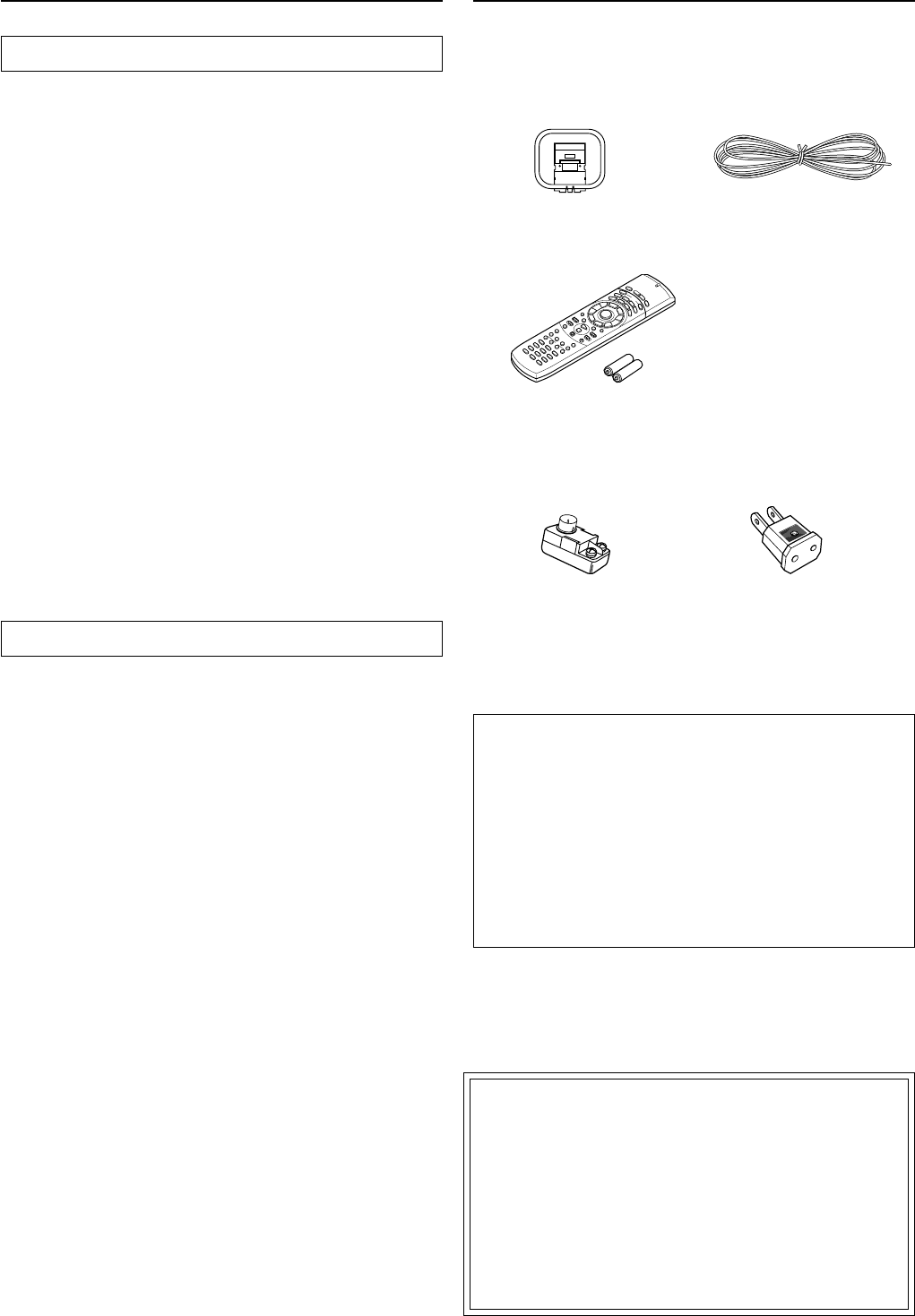
Check that the following accessories are supplied with this unit.
Supplied accessories
THX Select
Before any home theatre component can be THX Select certi-
fied, it must pass a rigorous series of quality and performance
tests. Only then can a product feature the THX Select logo,
which is your guarantee that the Home Theatre products you
purchase will give you superb performance for many years to
come. THX Select requirements define hundreds of param-
eters, including power amplifier performance, and pre-ampli-
fier performance and operation for both digital and analog do-
mains. THX Select receivers also features proprietary THX
technologies (e.g. THX Mode, see page 34) which accurately
translate film soundtracks for home theater playback.
5
Before operating this unit
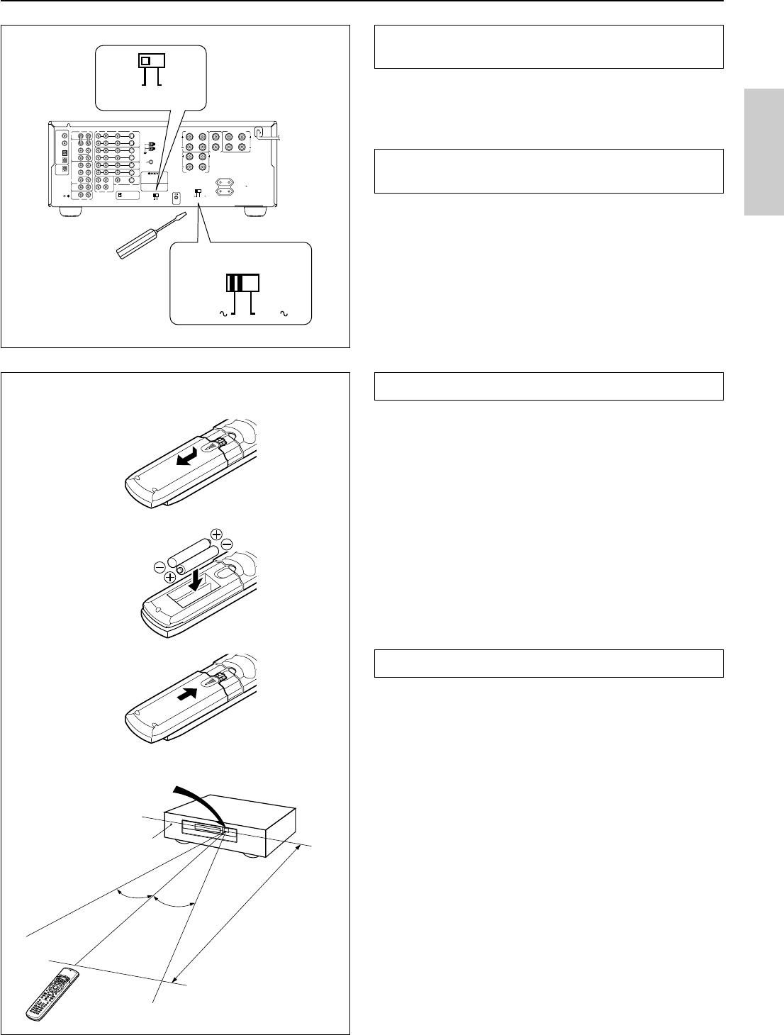
Setting the AM tuning step frequency
(Worldwide models only)
Worldwide models are equipped with a switch that controls the AM
band tuning steps. Please set this switch to match the AM band tun-
ing step frequency in your area.
U.S.A. and Canada: 10 kHz
Other areas: 9 kHz
Setting the Voltage selector
(Worldwide models only)
Worldwide models are equipped with a voltage selector to conform
with local power supplies. Be sure to set this switch to match the
voltage of the power supply in your area before plugging in the unit.
1.Determine the proper voltage for your area: 220-230 V or 120
V.
2.If the preset voltage is not correct for your area, insert a screw-
driver into the groove in the switch. Slide the switch all the way
to the right (120 V) or to the left (220-230 V), whichever is ap-
propriate.
R
V
L
R
L
R
L
R
L
R
L
VIDEO-1
OUT
IN
VIDEO-2
VIDEO-3
OUT
IN
IN
TAPE
VIDEO
S VIDEO
OSD SELECTOR
(REC)
OUT
IN
(PLAY)
DIGITAL OUTPUT
DIGITAL INPUT
COAXIAL
1
COAXIAL
2
OPTICAL
1
OPTICAL
2
OPTICAL
FRONT
FRONT
CENTER
SUB
WOOFER
SURROUND
FRONT
CENTER
CD
PHONO
SUB
WOOFER
SURROUND
AMP IN
PRE OUT
GMD
MONITOR
OUT
S
V
S
REMOTE
CONTROL
IN
DVD
LRLR
LR
SURROUND SPEAKERS
FRONT SPEAKERS A
CENTER
SPEAKER
FRONT SPEAKERS B
MULTI CHANNEL
INPUT
AV RECEIVER
CAUTION: SPEAKER IMPEDANCE
6 OHMS MIN. / SPEAKER
ANTENNA
AM
FM
75
AC OUTLETS
AC 230V 50Hz
SWITCHED
TOTAL 100W MAX.
120V
VOLTAGE SELECTOR
220-230V
10 kHz
AM FREQUENCY STEP
9 kHz
MODEL NO.
TX-DS777
120V
VOLTAGE SELECTOR
220-230V
10 kHz
AM FREQUENCY STEP
9 kHz
3
2
1
30˚
30˚
Remote control sensor
Receiver
STANDBY indicator
approx. 5 m
(16 feet)
Installing the remote controller batteries
1.Remove the battery compartment cover by pressing the tab and
lifting up the cover.
2.Insert two AA (R6- or UM-3)-size batteries into the battery
compartment. Carefully follow the polarity diagram (positive
(+) and negative (–) symbols) inside the battery compartment.
3.After batteries are installed and seated correctly, replace the
compartment cover.
Notes
•Do not mix new batteries with old batteries or different kinds of
batteries.
•To avoid corrosion, remove the batteries if the remote controller
is not to be used for a long time.
•Remove dead batteries immediately to avoid damage from cor-
rosion. If the remote controller doesn’t operate smoothly, re-
place both the batteries at the same time.
•The life of the batteries supplied is about six months but this will
vary depending on usage.
Using the remote controller
Point the remote controller toward the remote control sensor.
The STANDBY indicator lights up when the unit receives a signal
from the remote controller.
Notes
•Place the unit away from strong light such as direct sunlight or inverted
fluorescent light which can prevent proper operation of the remote con-
troller.
•Using another remote controller of the same type in the same room or
using the unit near equipment which uses infrared rays may cause op-
erational interference.
•Do not put any object such as a book on the remote controller. The but
tons of the remote controller may be pressed by mistake and drain the
batteries.
•Make sure the audio rack doors do not have colored glass. Placing the
unit behind such doors may prevent proper remote controller operation.
•If there is any obstacle between the remote controller and the remote
control sensor, the remote controller will not operate.
6
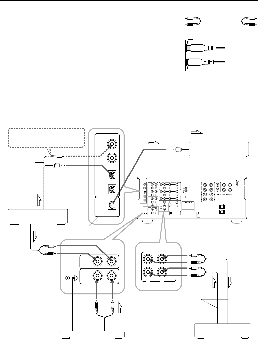
Audio equipment connections
•Do not piug in the power cord until all connections have been made.
•On each pair of input jacks, a red connector (marked R) corresponds to the right
channel, and a white connector (marked L) to the left channel.
•Please refer to the instruction manual of each component when making any con-
nections.
•Insert the plugs and connectors securely. Remember that improper connection
can result in noise, poor performance, or damage to the equipment.
•Do not bind audio connection calls with power cords and speaker cables. Doing so
may degrade sound quality.
L (Left)
R (Right)
Audio connection cable
L
R
Improper Connection
Insert completely
R
V
L
R
L
R
L
R
L
R
L
VIDEO-1
OUT
IN
VIDEO-2
VIDEO-3
OUT
IN
IN
TAPE
VIDEO
S VIDEO
OSD SELECTOR
(REC)
OUT
IN
(PLAY)
DIGITAL OUTPUT
DIGITAL INPUT
COAXIAL
1
COAXIAL
2
OPTICAL
1
OPTICAL
2
OPTICAL
FRONT
FRONT
CENTER
SUB
WOOFER
SURROUND
FRONT
CENTER
CD
PHONO
SUB
WOOFER
SURROUND
AMP IN
PRE OUT
GND
MONITOR
OUT
S
V
S
REMOTE
CONTROL
IN
DVD
LRLR
LR
SURROUND SPEAKERS
FRONT SPEAKERS A
CENTER
SPEAKER
FRONT SPEAKERS B
MULTI CHANNEL
INPUT
TX-DS777
ANTENNA
AM
FM
75
AC OUTLETS
SWITCHED
TOTAL 100W MAX.
W
DIGITAL OUTPUT
DIGITAL INPUT
COAXIAL
1
COAXIAL
2
OPTICAL
1
OPTICAL
2
OPTICAL
R
L
CD
PHONO
GND
R
L
TAPE
(REC)
OUT
IN
(PLAY)
Do not plug in the power
cord until all connections
have been made.
OUTPUT
(COAXIAL)
:Signal Flow
OUTPUT
(DIGITAL)
CD player
OUTPUT
(ANALOG)
Ground
OUTPUT
Turntable
Tape deck / MD recorder / DAT
OUTPUT
(PLAY)
INPUT
(REC)
TX-DS777 / TX-DS676
Audio Connection
Cable
Audio Connection Cable
Audio Connection
Cable
Optial fiber cable
Coaxial cable
Optial fiber cable
TX-DS777 only
MD recorder / DAT etc...
1
2
Connect your player to COAXIAL or OPTI-
CAL, whichever appropriate.
3
7
Audio equipment connections
AC outlet connection
You can connect the power cord from another
audio device to the rear of this receiver.
Since the AC outlets on the unit are a
SWITCHED type outlet, you can use the
STANDBY/ON button, to turn on/off the power
to both this receiver and the connected audio de-
vices.
First turn the POWER switch ON (
).
The shape, number, and total capacity of the AC
outlets may differ depending on the area of pur-
chase. Make sure that the total capacity of other
components connected to this unit does not ex-
ceed the capacity that is printed on the rear panel.
Connections for remote control (z)
You can use the remote controller of this receiver to operate
cassette tape decks and compact disc players that have Onkyo
z connectors.
Connect a remote control cable to the connector with the z
mark.
•An z remote control cable equipped with a 3.5mm (1/8
in.)-diameter miniature two-conductor phone plug comes
with every compact disc player or cassette tape deck that
has an z connector.
•Remote control operation is not possible if only the remote
control cable is connected – the audio connection cables
must also be connected.
•This receiver’s remote controller does not support control
of Onkyo turntables.
•If the connecting device has two z connectors lined-up
vertically or horizontally, you can use either of them. They
both offer the same functionality.
•You can use the remote controller for the TX-DS777/TX-
DS676 to control a Onkyo DVD player or MD recorder
that is not connected via an z cable. When you control
such a DVD player or MD recorder, point the remote con-
troller toward the sensor area of the DVD player or MD
recorder.
R
V
L
R
L
R
L
R
L
R
L
VIDEO-1
OUT
IN
VIDEO-2
VIDEO-3
OUT
IN
IN
TAPE
VIDEO
S VIDEO
OSD SELECTOR
(REC)
OUT
IN
(PLAY)
DIGITAL OUTPUT
DIGITAL INPUT
COAXIAL
1
COAXIAL
2
OPTICAL
1
OPTICAL
2
OPTICAL
FRONT
FRONT
CENTER
SUB
WOOFER
SURROUND
FRONT
CENTER
CD
PHONO
SUB
WOOFER
SURROUND
AMP IN
PRE OUT
GMD
MONITOR
OUT
S
V
S
REMOTE
CONTROL
IN
DVD
LRLR
LR
SURROUND SPEAKERS
FRONT SPEAKERS A
CENTER
SPEAKER
FRONT SPEAKERS B
MULTI CHANNEL
INPUT
AV RECEIVER
CAUTION: SPEAKER IMPEDANCE
6 OHMS MIN. / SPEAKER
ANTENNA
AM
FM
75
AC OUTLETS
AC 120V 60Hz
SWITCHED
TOTAL 120W 1A MAX.
MODEL NO.
TX-DS777
Capacity is total
120 watts.
U.S.A. and
Canadian models
Worldwide and
European models
Capacity is total
100 watts.
R
V
L
R
L
R
L
R
L
R
L
VIDEO-1
OUT
IN
VIDEO-2
VIDEO-3
OUT
IN
IN
TAPE
VIDEO
S VIDEO
OSD SELECTOR
(REC)
OUT
IN
(PLAY)
DIGITAL OUTPUT
DIGITAL INPUT
COAXIAL
1
COAXIAL
2
OPTICAL
1
OPTICAL
2
OPTICAL
FRONT
FRONT
CENTER
SUB
WOOFER
SURROUND
FRONT
CENTER
CD
PHONO
SUB
WOOFER
SURROUND
AMP IN
PRE OUT
GMD
MONITOR
OUT
S
V
S
REMOTE
CONTROL
IN
DVD
LRLR
LR
SURROUND SPEAKERS
FRONT SPEAKERS A
CENTER
SPEAKER
FRONT SPEAKERS B
MULTI CHANNEL
INPUT
AV RECEIVER
CAUTION: SPEAKER IMPEDANCE
6 OHMS MIN. / SPEAKER
ANTENNA
AM
FM
75
AC OUTLETS
AC 120V 60Hz
SWITCHED
TOTAL 120W 1A MAX.
MODEL NO.
TX-DS777
CD Player
TX-DS777/TX-DS676
Cassette Tape Deck
1.DIGITAL INPUT connectors
•If your CD player has a digital output connector, connect it to a proper DIGITAL INPUT connector for
clear and dynamic sound play.
•This unit provides four digital input connectors to connect CD players, MD recorders, DAT decks, etc.
having a digital output connector. When using these connectors, connect the unit also via the audio con-
nection cables. You should also note that the signals you can record are analog signals only.
•The digital inputs, COAXIAL 1, 2 and OPTICAL 1, 2can be assigned to individual input selector buttons,
so when an input selector button is pressed, the assigned digital input is used instead of the corresponding
analog input. (See page 23,29.)
2.OPTICAL DIGITAL OUTPUT connector (TX-DS777 only)
If you have a digital recorder, such as an MD recorder, DAT, and CD-R (Compact Disc Recorder), con-
nect the recorder’s digital input connector to this connector. In this case, always use commercially avail-
able optical digital audio cables.
3.Turntable
This receiver is designed for use with turntables using moving magnet cartridges.
Connect a ground (or earth) wire to GND terminal.
With some players, connecting a ground wire results in larger noise. If so, do not connect any ground wire.
Remove the protective
caps before making
connections. When not in
use, be sure to replace
them.
Optical digital connector
8
R
V
L
R
L
R
L
R
L
R
L
VIDEO-1
OUT
IN
VIDEO-2
VIDEO-3
OUT
IN
IN
TAPE
VIDEO
S VIDEO
OSD SELECTOR
(REC)
OUT
IN
(PLAY)
DIGITAL OUTPUT
DIGITAL INPUT
COAXIAL
1
COAXIAL
2
OPTICAL
1
OPTICAL
2
OPTICAL
FRONT
FRONT
CENTER
SUB
WOOFER
SURROUND
FRONT
CENTER
CD
PHONO
SUB
WOOFER
SURROUND
AMP IN
PRE OUT
GMD
MONITOR
OUT
S
V
S
REMOTE
CONTROL
IN
DVD
LRLR
LR
SURROUND SPEAKERS
FRONT SPEAKERS A
CENTER
SPEAKER
FRONT SPEAKERS B
MULTI CHANNEL
INPUT
AV RECEIVER
CAUTION: SPEAKER IMPEDANCE
6 OHMS MIN. / SPEAKER
ANTENNA
AM
FM
75
AC OUTLETS
AC 120V 60Hz
SWITCHED
TOTAL 120W 1A MAX.
MODEL NO. TX-DS777
R
V
L
VIDEO-1
OUT
IN
VIDEO-2
VIDEO-3
OUT
IN
IN
MONITOR
OUT
S
V
S
DIGITAL OUTPUT
DIGITAL INPUT
COAXIAL
1
COAXIAL
2
OPTICAL
1
OPTICAL
2
OPTICAL
IN
DVD
VIDEO
S VIDEO
OSD SELECTOR
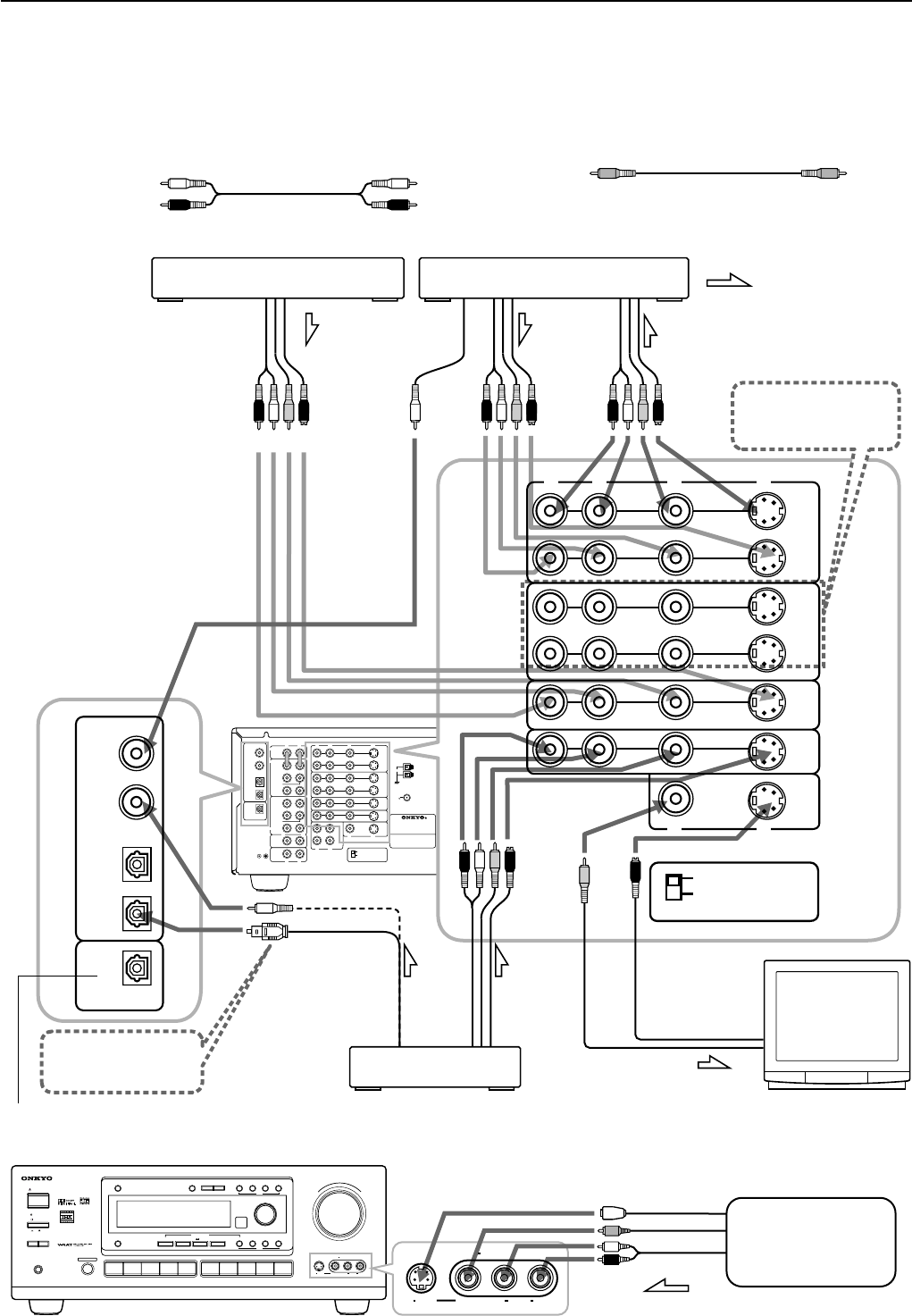
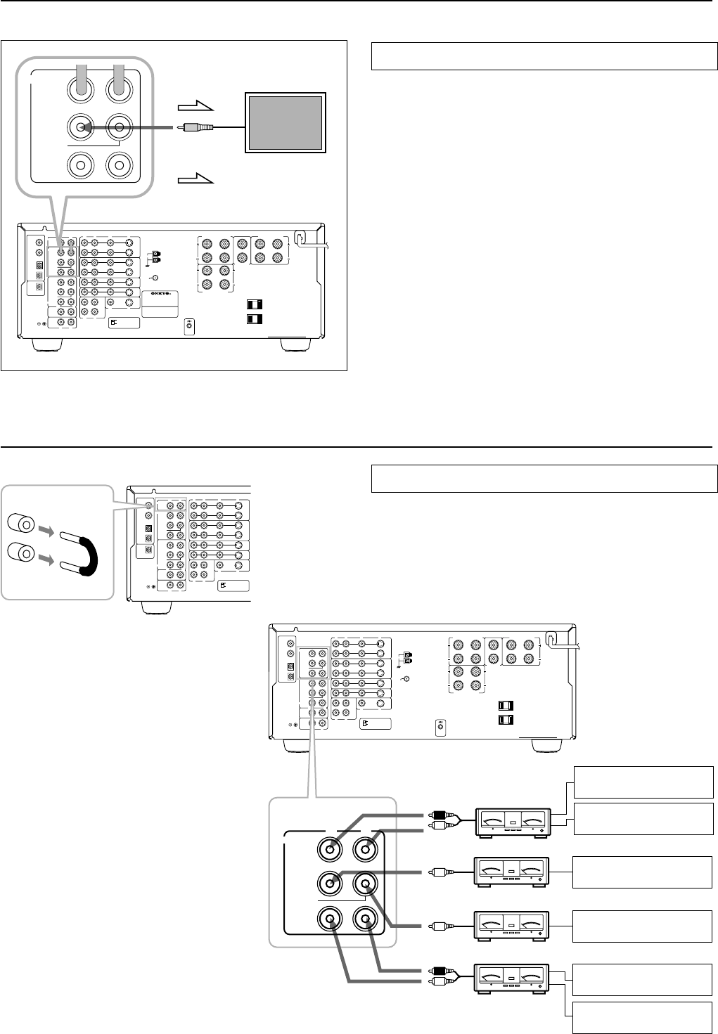
•On each pair of input jacks, a red connector (marked R) corresponds to the right channel, and a white connector (marked L) to
the left channel.
•A yellow connector (marked V) is used for video connection.
•Please refer to the instruction manual of each component when making any connections.
Video Disc Player
Digital video equipment
or Video cassette recorder
AUDIO
OUT
VIDEO
PUT
AUDIO
IN
VIDEO
IN
AUDIO
OUT
VIDEO
OUT
VIDEO IN
Monitor TV
DVD player
DIGITAL COAXIAL
OUTPUT
DIGITAL
OPTICAL
OUTPUT
:Signal flow
Video equipment connections
Video connection cable
MASTER VOLUME
STANDBY/ON
PHONES
VIDEO CAM INPUT/4VIDEO
VIDEOAUDIOLR
(
MONO
)
S VIDEO
STAND
-
BY
AV
RECEIVER
TX-DS
777
POWER
OFF
ON
A SPEAKERS B
TI CH
INPUTMUL
FM
AMPHONOC
D
TAPEVIDEO-1
DVD
VIDEO-4
VIDEO-3
VIDEO-2
D
O
W
N
U
P
FM MUTE/
MODE
CHARACTER/
MEMORY
SP/SYS
SETUP
MODE
AUDIO
ADJUSTMENT
BASS/
TREBLE
DISPLAYDSPREC OUT
PRESET/MODE ADJ
PUSH TO ENTER
DOWN TUNING UP
THX /DTS
SURROUNDMODE
LISTENING MODE
STEREODIRECT
DIGITAL/
ANALOG
CH LEVEL
DIMMER
VIDEO CAM INPUT/4VIDEO
VIDEOAUDIOLR
(
MONO
)
SVIDEO
DIGITAL
OUT
VIDEO
OUTPUT
AUDIO
OUTPUT
L (Left)
R (Right)
L
R
Audio connection cable
1
3
4
5
2
TX-DS777
only
6
Video camera etc...
Note:
The screen images may become dim
depending on the video source being
selected (for example, a satellite-broadcast
tuner unit such as a set-top box). If so,
connect the video source to the VIDEO-3
connector.
9
R
V
L
R
L
R
L
R
L
R
L
VIDEO-1
OUT
IN
VIDEO-2
VIDEO-3
OUT
IN
IN
TAPE
VIDEO
S VIDEO
OSD SELECTOR
(REC)
OUT
IN
(PLAY)
DIGITAL OUTPUT
DIGITAL INPUT
COAXIAL
1
COAXIAL
2
OPTICAL
1
OPTICAL
2
OPTICAL
FRONT
FRONT
CENTER
SUB
WOOFER
SURROUND
FRONT
CENTER
CD
PHONO
SUB
WOOFER
SURROUND
AMP IN
PRE OUT
GMD
MONITOR
OUT
S
V
S
REMOTE
CONTROL
IN
DVD
LRLR
LR
SURROUND SPEAKERS
FRONT SPEAKERS A
CENTER
SPEAKER
FRONT SPEAKERS B
MULTI CHANNEL
INPUT
AV RECEIVER
CAUTION: SPEAKER IMPEDANCE
6 OHMS MIN. / SPEAKER
ANTENNA
AM
FM
75
AC OUTLETS
AC 120V 60Hz
SWITCHED
TOTAL 120W 1A MAX.
MODEL NO.
TX-DS777
IN
DVD
RVLS
R
L
FRONT
CENTER
SUB
WOOFER
SURROUND
MULTI CHANNEL
INPUT
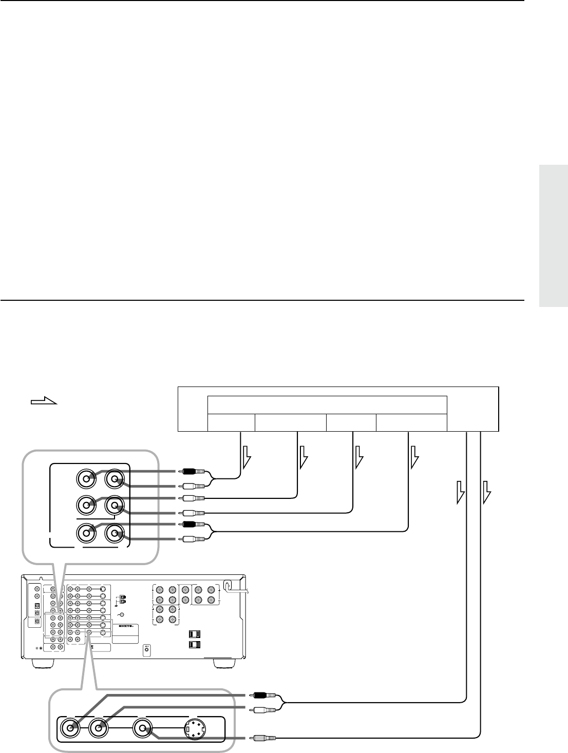
Decoder with 5.1 channel output
You may connect the 5.1 channel outputs of an external decoder (such as MPEG decoder and DVD player) to the MULTI CHANNEL
INPUTs of this unit.
:Signal flow
DVD player or a decoder with Multi (5.1) channel outputs
FRONT OUT
SUBWOOFER OUT
CENTER OUT
SURROUND OUT
TX-DS777
AUDIO OUT
VIDEO OUT
Multi (5.1) channel outputs
FrontSubwooferCenterSurround
Connecting equipment with 5.1-channel output
Video equipment connections
1.Digital audio connections
This receiver has a powerful digital signal processor for use with DVD players, DAT decks, and CD players. The digital inputs, CO-
AXIAL 1, 2 and OPTICAL 1, 2can be assigned to individual input selector buttons, so when an input selector button is pressed, the
assigned digital input is used instead of the corresponding analog input. (See page 23,29.)
2.Connect your second video cassette deck.
3.Connect your DVD player to COAXIAL or OPTICAL, whichever appropriate.
4.OSD SELECTOR:
Selects whether to output the OSD (On-Screen Display) information with the Video signals or the S-Video signals. Select "S VIDEO"
when the monitor is connected via the S-Video terminal.
5.Connecting video equipment through S-video connectors
•The signals input from the S IN jack will be output only to the S OUT jack; the signals input from the V IN jack will be output only to the
V OUT jack.
•For information on whether you need to connect either S or V jack or both of them, please refer to the instruction manual that came with
your video equipment.
6.Connect your video camera or TV game machine to the VIDEO-4 / VIDEO CAM INPUT jacks.
If a momaural video camera is used, connect its audio connection cable to “ R(MONO)” audio jack.
Notes:
•When using a playback-only VCR, connect it to VIDEO 3 or VIDEO 4. If you connect it to VIDEO 1 or VIDEO 2, you need to make only the input
connections.
•This receiver can be used with only a monitor TV equipped with a video input or S video jack.
•Interference may be caused between the TV and this receiver. If this interference occurs, place the receiver and the TV as far apart as possible. We do not
recommend the use of a common TV/FM antenna (see antenna section).
•Remove the protective cap attached to the DIGITAL INPUT/OUTPUT (OPTICAL) jack before making the connection. When this jack is not used,
replace the protective cap.
10
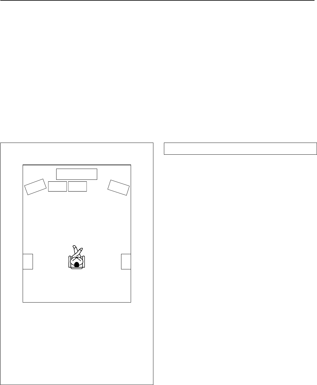
Connecting speakers
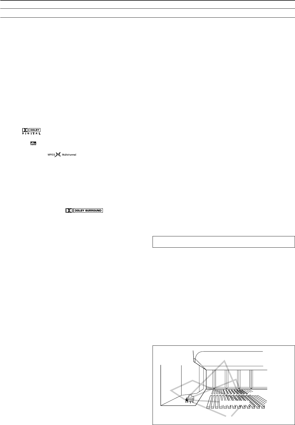
Speaker placement
Ideal speaker placement varies depending on the size of your room
and the wall coverings. Here, only typical example of speaker place-
ment and recommendations are shown.
Speaker systems
Left and Right front speakers and Center speaker
•Place these three speakers at the same height from the floor.
•Place each speaker so that sound is aimed at the audience's ears
at the listening position.
Left and Right surround speakers
•Place these speakers so that their height is 1 meter higher than
that of the audience's ears.
Subwoofer
To get the highest bass effect, place a subwoofer.
You can place your subwoofer anywhere in your room because the
placement affects very little the perceived sound.
1TV or Screen
2Front speaker Left
3Subwoofer
4Center speaker
5Front speaker Right
6Surround speaker Left
7Surround speaker Right
8Listening Position
1
2
3
5
4
67
8
The TX-DS777/676 allows you to connect two speaker systems.
Before connecting the speakers, place them correctly by consulting the instruction manuals that came with your speakers.
For surround playback (see “Using the listening modes” on page 34), the configuration and placement of your speakers are very important.
For Home THX cinema surround playback, we recommend that you use a THX speaker system that is certified by Lucasfilm Ltd. (such as
Onkyo HTS SYSTEM-2).
Ideal speaker configuration:
•Right and Left front speakers
•Center speaker
Produces a rich sound image by serving as a sound source for
the Right and Left front speakers and enhancing the sonic move-
ment.
•Right and Left surround speakers
Adds three-dimensional sonic movement and produces environ-
mental sound associated with the background and effect sound
for each scene.
•Subwoofer
Produces powerful and heavy bass.
Minimum speaker configuration for surround sound playback:
•Right and Left front speakers
•Right and Left surround speakers
The sound recorded for the center speaker and the subwoofer will be
properly distributed to the Right and Left front speakers and the
Right and Left surround speakers for optimized surround playback.
11
R
V
L
R
L
R
L
R
L
R
L
VIDEO-1
OUT
IN
VIDEO-2
VIDEO-3
OUT
IN
IN
TAPE
VIDEO
S VIDEO
OSD SELECTOR
(REC)
OUT
IN
(PLAY)
DIGITAL OUTPUT
DIGITAL INPUT
COAXIAL
1
COAXIAL
2
OPTICAL
1
OPTICAL
2
OPTICAL
FRONT
FRONT
CENTER
SUB
WOOFER
SURROUND
FRONT
CENTER
CD
PHONO
SUB
WOOFER
SURROUND
AMP IN
PRE OUT
GMD
MONITOR
OUT
S
V
S
REMOTE
CONTROL
IN
DVD
LRLR
LR
SURROUND SPEAKERS
FRONT SPEAKERS A
CENTER
SPEAKER
FRONT SPEAKERS B
MULTI CHANNEL
INPUT
AV RECEIVER
CAUTION: SPEAKER IMPEDANCE
6 OHMS MIN. / SPEAKER
ANTENNA
AM
FM
75
AC OUTLETS
AC 120V 60Hz
SWITCHED
TOTAL 120W 1A MAX.
MODEL NO.
TX-DS777
RLR
LR
SURROUND SPEAKERS
FRONT SPEAKERS A
CENTER
SPEAKER
FRONT SPEAKERS B
L
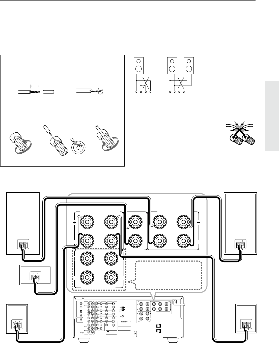
Connecting speakers
•This receiver is designed to produce optimum sound quality when speakers with impedances within the specified ranges are connected.
Please check the following information and choose speakers with appropriate impedances for the connections.
FRONT SPEAKERS:A or B: 6 ohms min./speaker
SURROUND SPEAKERS:6 ohms min./speaker
CENTER SPEAKER:6 ohms min.
TX-DS777/TX-DS676
Center Speaker
Surround Speaker
R ch.
Front SpeakerA
R ch.
Surround Speaker
L ch.
Front SpeakerA
L ch.
Note:
To prevent damage to circuitry, never short-circuit
the positive (+) and negative (–) speaker wire.
•When you use only one
speaker or wish to listen to
monaural (mono) sound, a
single speaker should never
be connected in parallel to
both the right and left chan-
nel terminals simulta-
neously.
+––++––+
RLRL
Connecting the speaker cable
1.Twist wire ends very tight.
2.Unscrew3.Insert wire4.Screw
Use Front SPEAKERS B termi-
nals to connect a second pair of
front speakers.
15mm
No!
No!
12
R
V
L
R
L
R
L
R
L
R
L
VIDEO-1
OUT
IN
VIDEO-2
VIDEO-3
OUT
IN
IN
TAPE
VIDEO
S VIDEO
OSD SELECTOR
(REC)
OUT
IN
(PLAY)
DIGITAL OUTPUT
DIGITAL INPUT
COAXIAL
1
COAXIAL
2
OPTICAL
1
OPTICAL
2
OPTICAL
FRONT
FRONT
CENTER
SUB
WOOFER
SURROUND
FRONT
CENTER
CD
PHONO
SUB
WOOFER
SURROUND
AMP IN
PRE OUT
GMD
MONITOR
OUT
S
V
S
REMOTE
CONTROL
IN
DVD
LRLR
LR
SURROUND SPEAKERS
FRONT SPEAKERS A
CENTER
SPEAKER
FRONT SPEAKERS B
MULTI CHANNEL
INPUT
AV RECEIVER
CAUTION: SPEAKER IMPEDANCE
6 OHMS MIN. / SPEAKER
ANTENNA
AM
FM
75
AC OUTLETS
AC 120V 60Hz
SWITCHED
TOTAL 120W 1A MAX.
MODEL NO. TX-DS777
FRONT
CENTER
SUB
WOOFER
SURROUND
PRE OUT
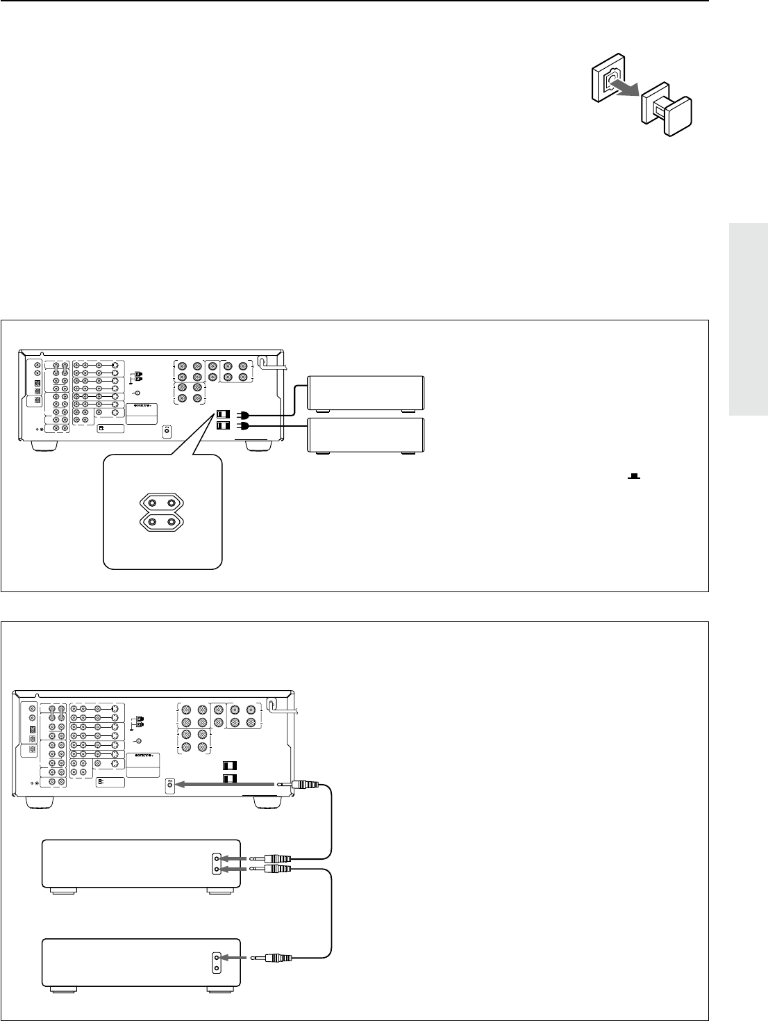
Connecting power amplifiers
Connecting power amplifiers
Using auxiliary power amplifiers allows you to listen at louder vol-
umes than with the TX-DS777/676 alone. If power amplifiers are
used, connect each speaker to the corresponding power amplifier.
When using speakers connected through external power amplifiers,
turn OFF the SPEAKERS A.
R
V
L
R
L
R
L
R
L
R
L
VIDEO-1
OUT
IN
VIDEO-2
VIDEO-3
OUT
IN
IN
TAPE
VIDEO
S VIDEO
OSD SELECTOR
(REC)
OUT
IN
(PLAY)
DIGITAL OUTPUT
DIGITAL INPUT
COAXIAL
1
COAXIAL
2
OPTICAL
1
OPTICAL
2
OPTICAL
FRONT
FRONT
CENTER
SUB
WOOFER
SURROUND
FRONT
CENTER
CD
PHONO
SUB
WOOFER
SURROUND
AMP IN
PRE OUT
GMD
MONITOR
OUT
S
V
S
IN
DVD
MULTI CHANNEL
INPUT
TX-DS777
TX-DS777/676
R
V
L
R
L
R
L
R
L
VIDEO-1
OUT
IN
VIDEO-2
VIDEO-3
OUT
IN
IN
TAPE
VIDEO
S VIDEO
OSD SELECTOR
(REC)
OUT
IN
(PLAY)
DIGITAL INPUT
COAXIAL
1
COAXIAL
2
OPTICAL
1
OPTICAL
2
FRONT
CENTER
SUB
WOOFER
SURROUND
FRONT
CENTER
CD
PHONO
SUB
WOOFER
SURROUND
PRE OUT
GMD
MONITOR
OUT
S
V
S
REMOTE
CONTROL
IN
DVD
LRLR
LR
SURROUND SPEAKERS
FRONT SPEAKERS A
CENTER
SPEAKER
FRONT SPEAKERS B
MULTI CHANNEL
INPUT
CAUTION: SPEAKER IMPEDANCE
6 OHMS MIN. / SPEAKER
ANTENNA
AM
FM
75
AC OUTLETS
AC 120V 60Hz
SWITCHED
TOTAL 120W 1A MAX.
FRONT
CENTER
SUB
WOOFER
SURROUND
PRE OUT
R
L
Right front Speaker
Left front Speaker
Subwoofer
Center Speaker
Left Surround Speaker
Right Surround Speaker
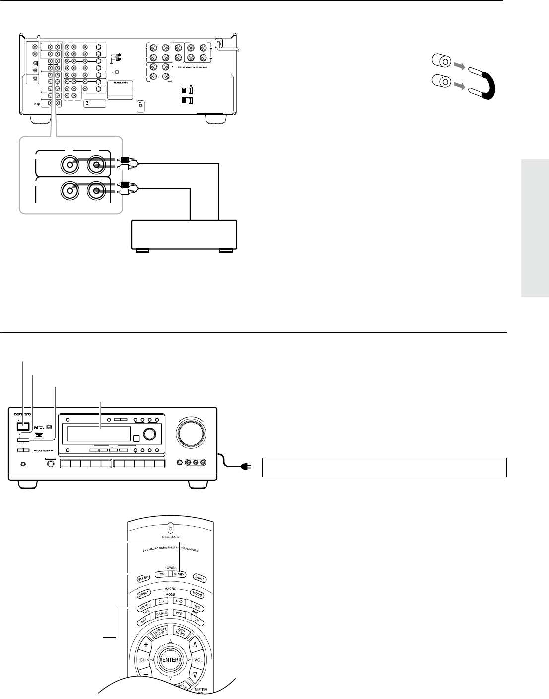
Notes:
•Keep the jumper plugs so that you will not
lose them.
•When the connectors are not in use, replace
the jumper plugs.
Connecting speakers
Connecting a subwoofer
Use the PREOUT SUBWOOFER jack to connect a subwoofer with
a built-in power amplifier. If your subwoofer does not have a built-
in amplifier, connect an amplifier to the PREOUT SUBWOOFER
jack and the subwoofer to the amplifier.
:Signal flow
13
Connecting the power
Connecting the power
•Before you plug in the receiver, confirm that all connections
have been made properly.
•Turning on this receiver’s power may cause a momentary power
surge, which might interfere with other electrical equipment,
such as computers. If this happens, use a wall outlet on a differ-
ent circuit.
1.Plug the power cord into an AC wall outlet.
2.Press the POWER switch to set the receiver to Standby
mode.
The STANDBY indicator will light up.
3.Press the STANDBY/ON button to turn on the receiver. The
display will light up and the STANDBY indicator will be
turned off.
If you press the STANDBY/ON button, the receiver returns to
Standby mode.
Turning the power on from the remote controller:
1.Press the MODE AUDIO button.
2.Press the POWER ON button to turn on the power to the
receiver, or press the POWER STNBY button to set the re-
ceiver in standby mode.
•You cannot use the remote controller if the POWER switch on
the receiver is set to OFF.
•Set the volume level to minimum before you turn off the power
to the receiver.
2. POWER ON
button
MASTER VOLUME
STANDBY/ON
PHONES
VIDEO CAM INPUT/4VIDEO
VIDEOAUDIOLR
(
MONO
)
S VIDEO
STAND
-
BY
AV
RECEIVER
TX-DS
777
POWER
OFF
ON
A SPEAKERS B
TI CH
INPUTMUL
FM
AMPHONOC
D
TAPEVIDEO-1
DVD
VIDEO-4
VIDEO-3
VIDEO-2
D
O
W
N
U
P
FM MUTE/
MODE
CHARACTER/
MEMORY
SP/SYS
SETUP
MODE
AUDIO
ADJUSTMENT
BASS/
TREBLE
DISPLAYDSPREC OUT
PRESET/MODE ADJ
PUSH TO ENTER
DOWN TUNING UP
THX /DTS
SURROUNDMODE
LISTENING MODE
STEREODIRECT
DIGITAL/
ANALOG
CH LEVEL
DIMMER
2. POWER STNBY
button
1. MODE AUDIO
button
3. STANDBY/ON button
STANDBY indicator
Display
2. POWER switch
1. To wall outlet
Connecting an equalizer (TX-DS777)
The AMP IN and the PREOUT FRONT connectors are attached
with jumper plugs. When connecting an equalizer, remove these
jumper plugs before connecting the audio connection cables.
1.Remove the jumper plugs.
See “Connecting power amplifiers.”
2.Connect an equalizer.
TX-DS777
Input jack
R
V
L
R
L
R
L
R
L
R
L
VIDEO-1
OUT
IN
VIDEO-2
VIDEO-3
OUT
IN
IN
TAPE
VIDEO
S VIDEO
OSD SELECTOR
(REC)
OUT
IN
(PLAY)
DIGITAL OUTPUT
DIGITAL INPUT
COAXIAL
1
COAXIAL
2
OPTICAL
1
OPTICAL
2
OPTICAL
FRONT
FRONT
CENTER
SUB
WOOFER
SURROUND
FRONT
CENTER
CD
PHONO
SUB
WOOFER
SURROUND
AMP IN
PRE OUT
GMD
MONITOR
OUT
S
V
S
REMOTE
CONTROL
IN
DVD
LRLR
LR
SURROUND SPEAKERS
FRONT SPEAKERS A
CENTER
SPEAKER
FRONT SPEAKERS B
MULTI CHANNEL
INPUT
TX-DS777
ANTENNA
AM
FM
75
AC OUTLETS
SWITCHED
TOTAL 100W MAX.
W
R
L
FRONT
FRONT
AMP IN
PRE OUT
Output jack
Input jack
Epualizer
14
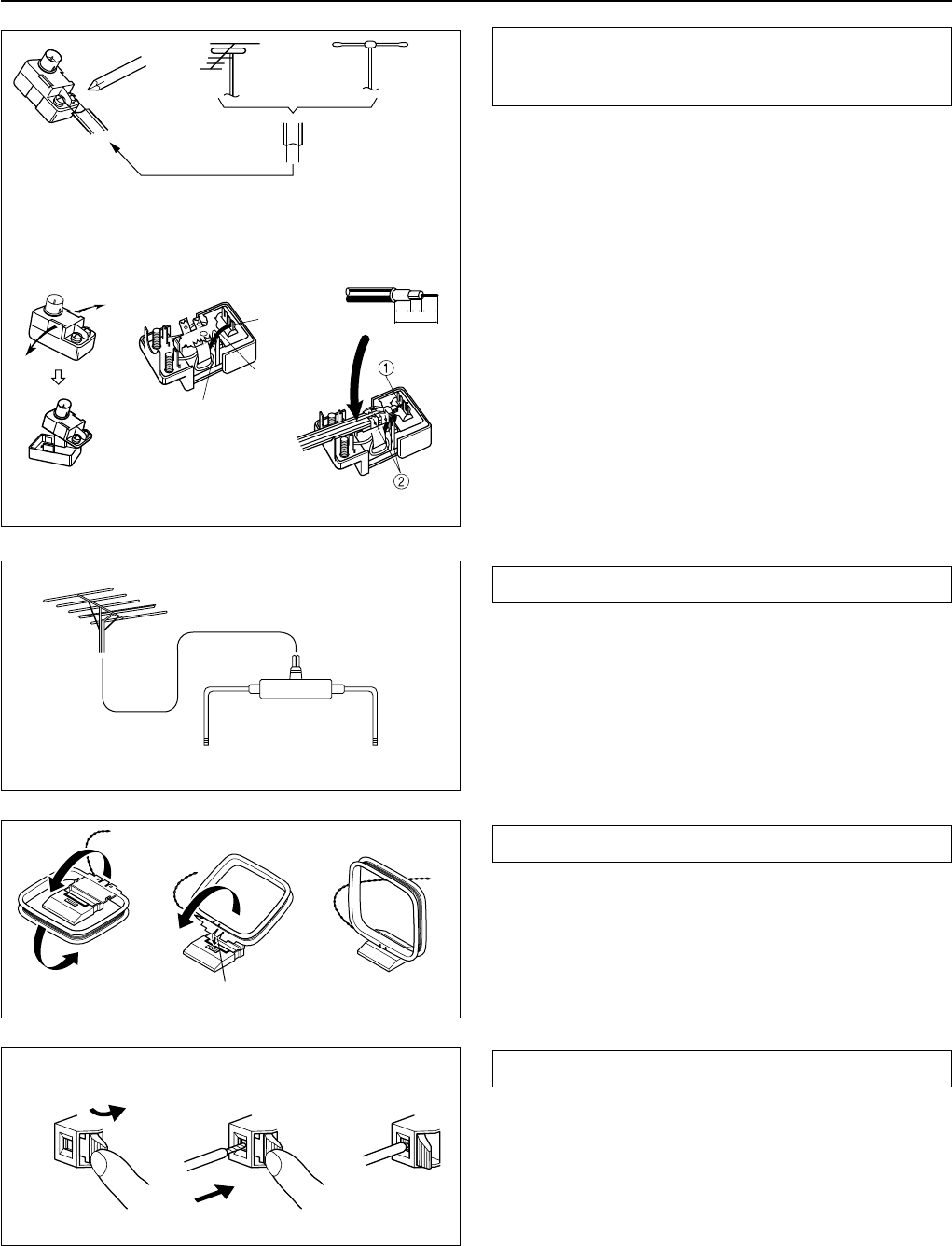
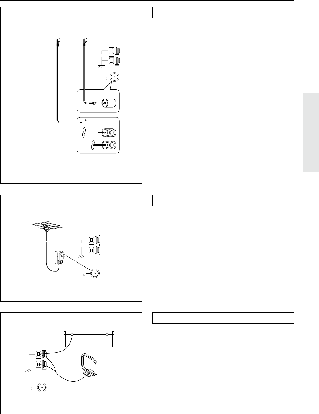
Making antenna connections
Connecting the antenna cable to the 75/300 ohm
antenna adapter (Other than North America and
European models)
Connecting the 300 ohm ribbon wire:
Loosen the screws and wrap the wire around these screws. Then
tighten the screws with a screwdriver.
Connecting the coaxial cable:
1.With your fingernail or a small screwdriver, press the stoppers
outward and remove the cover.
2.Remove the transformer wire A from slit B and insert it into slit
C.
3.Prepare the coaxial cable as shown in the diagram.
Connect the 75/300 ohm antenna adapter to the coaxial cable.
1Insert the end of the cable.
2Clamp it in place with pliers.
4.Re-install the cover.
Directional Iinkage
Do not use the same antenna for both FM and TV (or VCR) recep-
tion since the FM and TV (or VCR) signals can interfere with each
other. If you must use a common FM/TV (or VCR) antenna, use a
directional linkage type splitter.
Assembling the AM loop antenna
Assemble the loop antenna as shown in the illustration.
•Refer to the next page for details on connecting the AM loop
antenna.
Connecting the antenna cable
1.Press down the lever.
2.Insert the wire into the hole.
3.Release the lever to replace it.
123
✦
✦
✦
✦
✦
✦
✦
✦
✦
✦
✦
6
mm
3
mm
6
mm
15mm
12
3
Outdoor
antenna
Indoor
antenna
300 ohms
ribbon wire
Slit B
Wire A
Slit C
Directional linkage
type splitter
To TV (or VCR)
To receiver
Insert into the hole.
15
Connecting the included antennas
Connecting the FM indoor antenna:
The FM indoor antenna is for indoor use only. Extend the antenna
and move it in various directions until the clearest signal is received.
Fix it with push pins or similar implements in the position that will
cause the least amount of distortion.
If the reception is not very clear with the attached FM indoor an-
tenna, the use of an outdoor antenna is recommended.
Making antenna connections
Connecting an FM outdoor antenna
Please make sure that you follow the considerations below regard-
ing the location.
Keep the antenna away from noise sources (neon signs, busy roads,
etc.).
It is dangerous to put the antenna close to power lines. Keep it well
away from power lines, transformers, etc.
•To avoid the risk of lightning and electrical shock, grounding is
necessary. Follow item 19 of the “Important Safeguards” on
page 2 when you install the outdoor antenna.
Connecting the AM loop antenna:
The AM loop antenna is for indoor use only. Set it in the direction
and position where you receive the clearest sound. Put it as far away
as possible from the unit, TVs, speaker cables, and power cords.
When reception is not satisfactory with the attached AM loop an-
tenna alone, connection of an outdoor antenna is recommended.
AM
FM
75
ANTENNA
Remove the insulation at
the end of the cable, then
fully insert the stripped
end of the cable.
AM
FM
75
ANTENNA
AM
FM
75
ANTENNA
U.S. and Canadian
models
Others
Outdoor
antenna
Connecting an AM outdoor antenna
The outdoor antenna will be more effective if it is stretched horizon-
tally above a window or outside.
•Do not remove the AM loop antenna.
•To avoid the risk of lightning and electrical shock, grounding is
necessary. Follow item 19 of the “Important Safeguards” on
page 2 when you install the outdoor antenna.
16
1
2~4
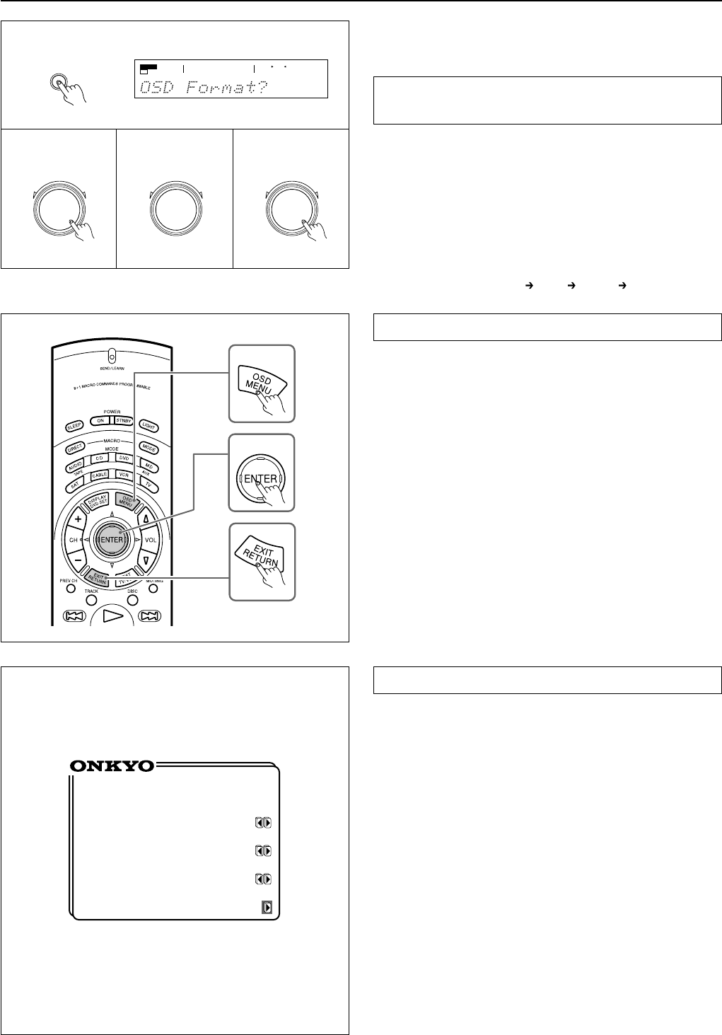
Using the on-screen display
Using the OSD (on-screen display) function lets you display each
screen on your TV so that you can perform various settings using
only the remote controller.
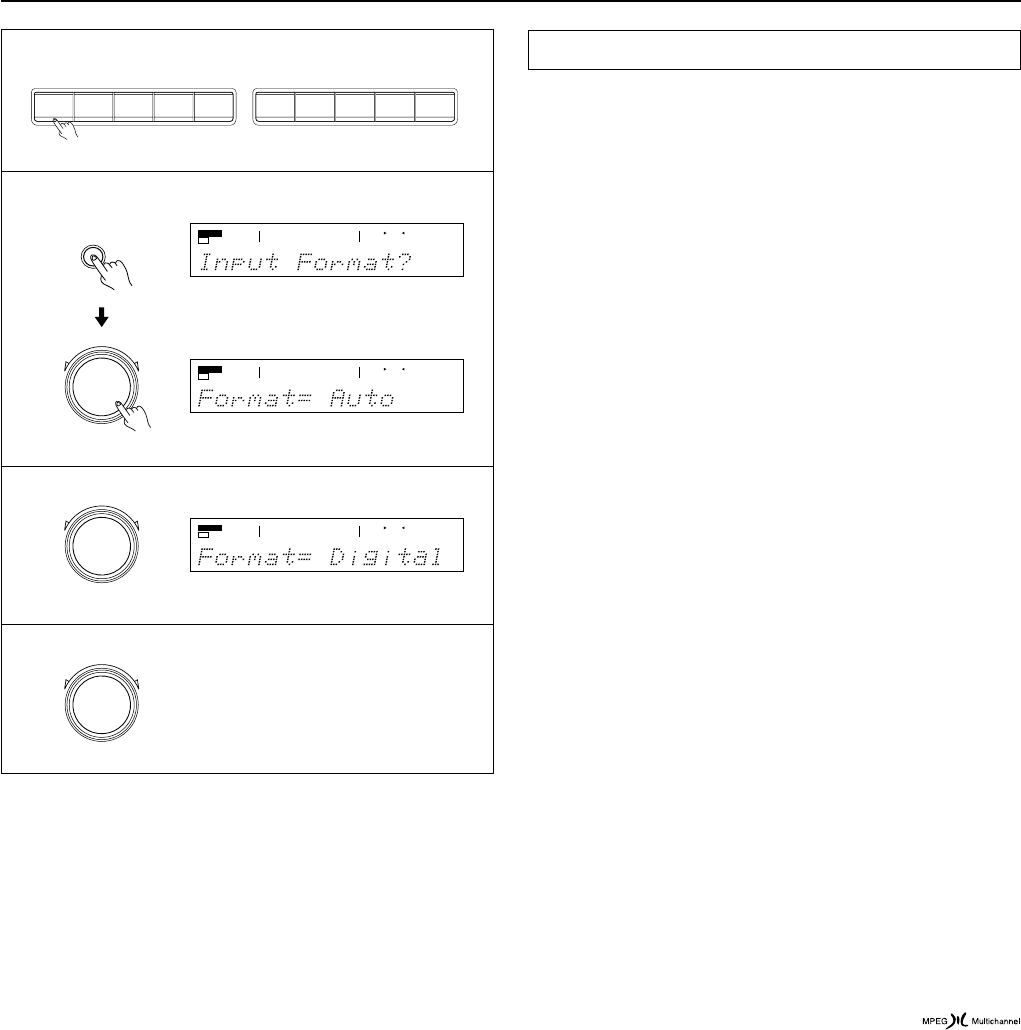
Setting the NTSC/PAL format
(European/worldwide model only)
The OSD format defaults to “Auto,” which means the OSD format
is set automatically. You can change this factory-set default as fol-
lows:
1.Press the SP/SYS SETUP button repeatedly until “OSD
Format?” appears.
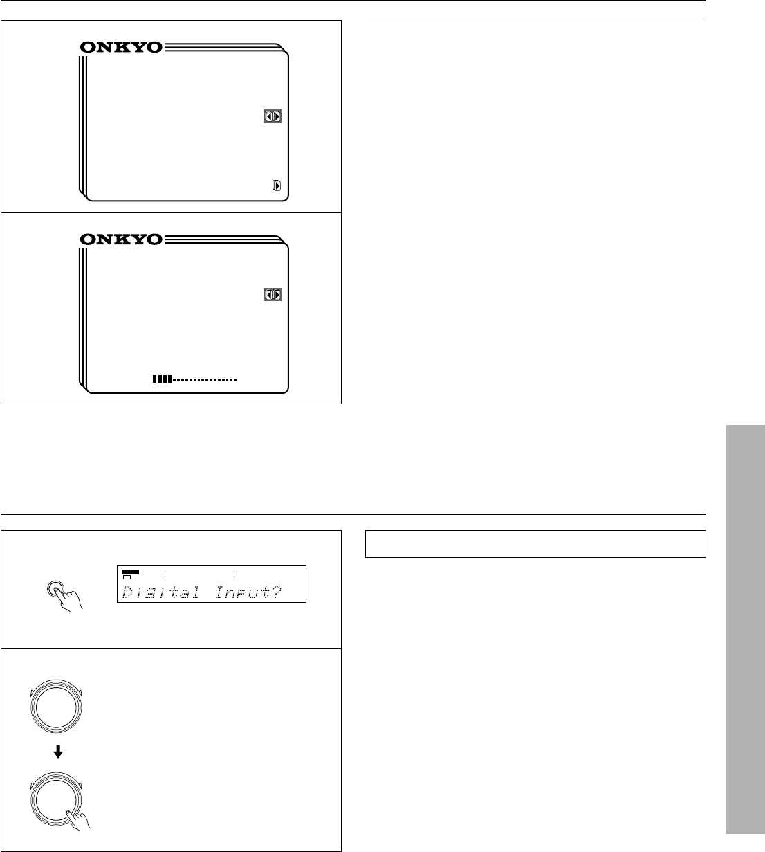
2.Press the SMART SCAN CONTROLLER.
The unit enters the NTSC/PAL setting mode.
3.Rotate the SMART SCAN CONTROLLER to select the
OSD format.
The display changes as below. Select the OSD format used in
your TV.
Auto (Automatic setting)
PAL NTSC (Auto)
4.Press the SMART SCAN CONTROLLER.
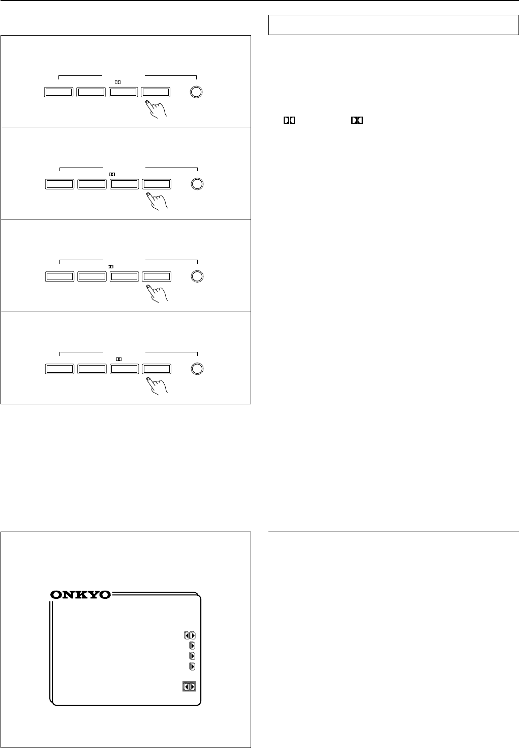
How to use the on-screen display
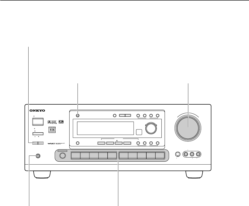
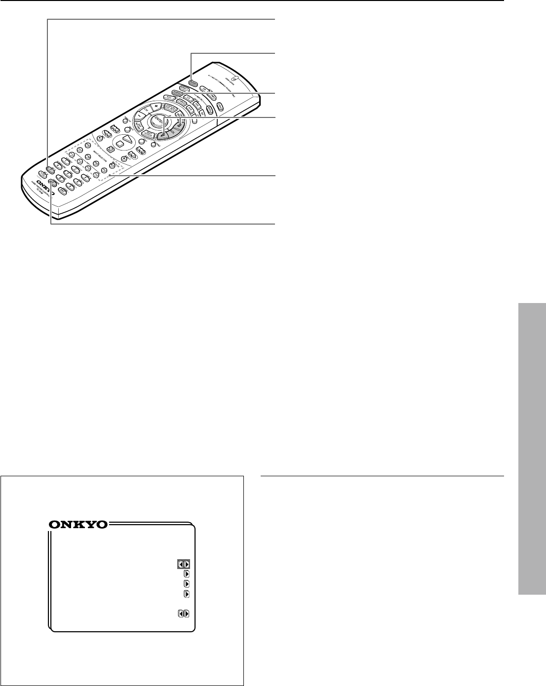
1.Press the OSD MENU button.
The on-screen display appears.
2.Press the upper or lower edge of the ENTER/Cursor button
to select the item.
The items you can select on each screen are shown on the next
page.
3.Press the right edge of the ENTER/Cursor button to display
the setting screen.
On each screen, you can press the upper or lower edge of the
ENTER/Cursor button to select an item and then press the right
or left edge of the button to change the setting.
If the item has an additional screen, you can press the right edge
of the button to change to that screen.
4.Press the center of the ENTER/Cursor button.
Use either of the following methods to turn off the on-screen
display.
•Press the center of the ENTER/Cursor button.
By pressing this button, you can follow in reverse the sequence
in which you have displayed each setting screen. Finally, the on-
screen display disappears.
•Press the EXIT button.
The on-screen display disappears immediately.
2
1
SP/SYS
SETUP
PRESET/MODE ADJ
PUSH TO ENTER
** Screen Setup **
Background
Color= Green 1
Superimpose
Mode= Normal
Immediate
Display= ON
Character Position
Screen Setup
Use the on-screen display to set the background color, the superim-
pose mode, etc.
1.Press the OSD MENU button.
2.Select “Screen Setup” and press the right edge of the EN-
TER/Cursor button.
3.Press the upper or lower edge of the ENTER/Cursor button
to select each item and then press the right or left edge of the
button to set a parameter.
Background Color : Select the desired color from BLUE-1, BLUE-2,
GREEN-1, GREEN-2, MAGENTA, RED-1, and RED-2.
Superimpose Mode : Select one of the following:
OFF : The on-screen display appears on the selected background
color.
Normal : The on-screen display is superimposed on images when
video signals are input and shown on the selected background color
when no video signal is input.
Black : The on-screen display appears on black screen.
Immediate Display : Select either “ON” or “OFF.” When set to “ON,”
the screen will show for 3 seconds the result (or process) of the
operation every time you operate the unit. For example, the volume
level indicator appears on the screen when you increase the sound
volume.
Character Position : Using the ENTER/Cursor button, move the on-
screen display to the lower left, upper left, upper right, or lower
right of the TV screen.
4.Press the center of the ENTER/Cursor button, or press the
EXIT button.
3
SPEAKERS
A
TUNED
AUTO
34
PRESET/MODE ADJ
PUSH TO ENTER
PRESET/MODE ADJ
PUSH TO ENTER
17
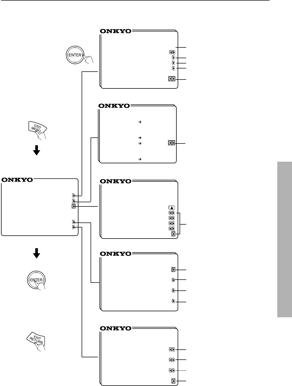
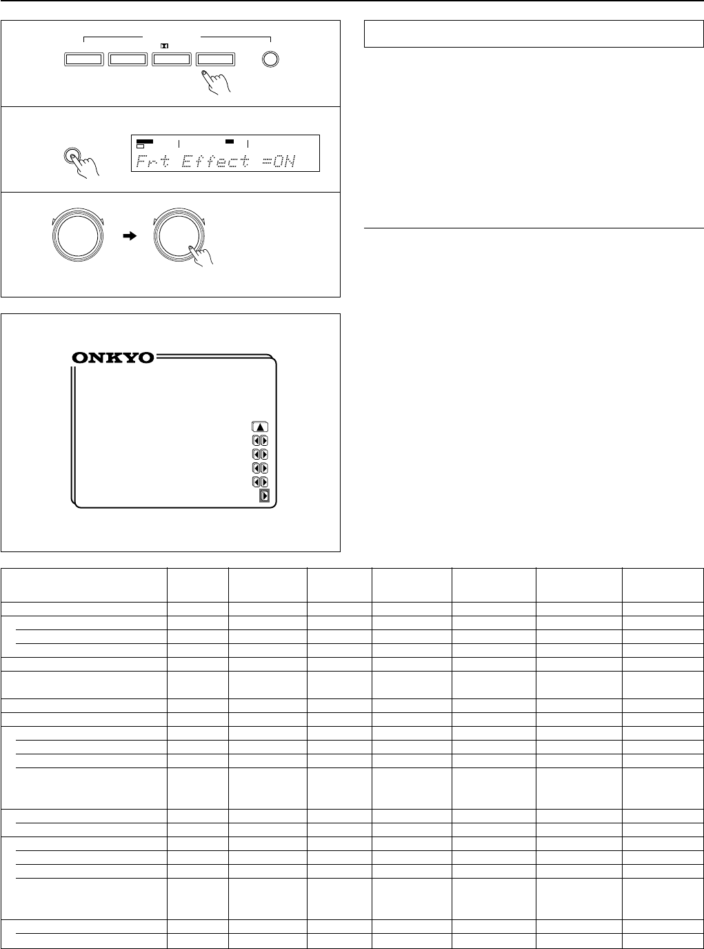
Using the on-screen display
*** Menu ***
Input Selector
Rec Selector
Listening Mode Setup
Speaker Setup
Screen Setup
** Input Selector **
Input = DVD
OPTICAL 1
Digital Input Setup
Video Assign Setup
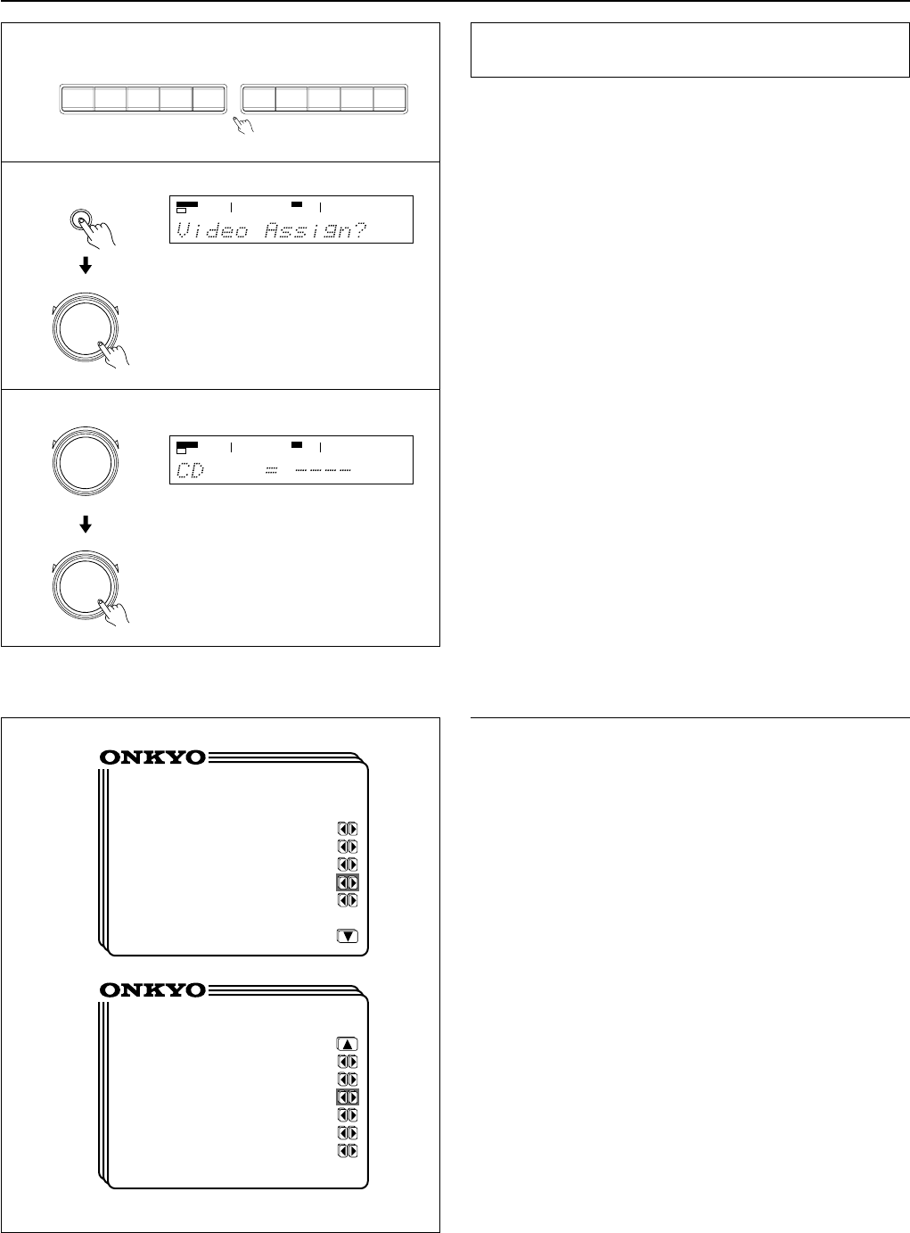
IntelliVolume Setup
Listening Dolby
Mode= Pro Logic
THX Cinema
** Rec Selector **
•PictureVIDEO
=DVD 1,2
•SoundTAPE
=DVDVIDEO
1,2
•DigitalOPTICAL
=
----
OUT
** Listening Mode **
Setup
Listening
Mode=Mono Movie
Front Effect= ON
Reflect Level= 0dB
Reverb Level= 0dB
Room Size=Mid
Default
** Speaker Setup **
Config Setup
Distance Setup
Level Setup
Bass Peak Setup
** Screen Setup **
Background
Color= Green 1
Superimpose
Mode= Normal
Immediate
Display= ON
Character Position
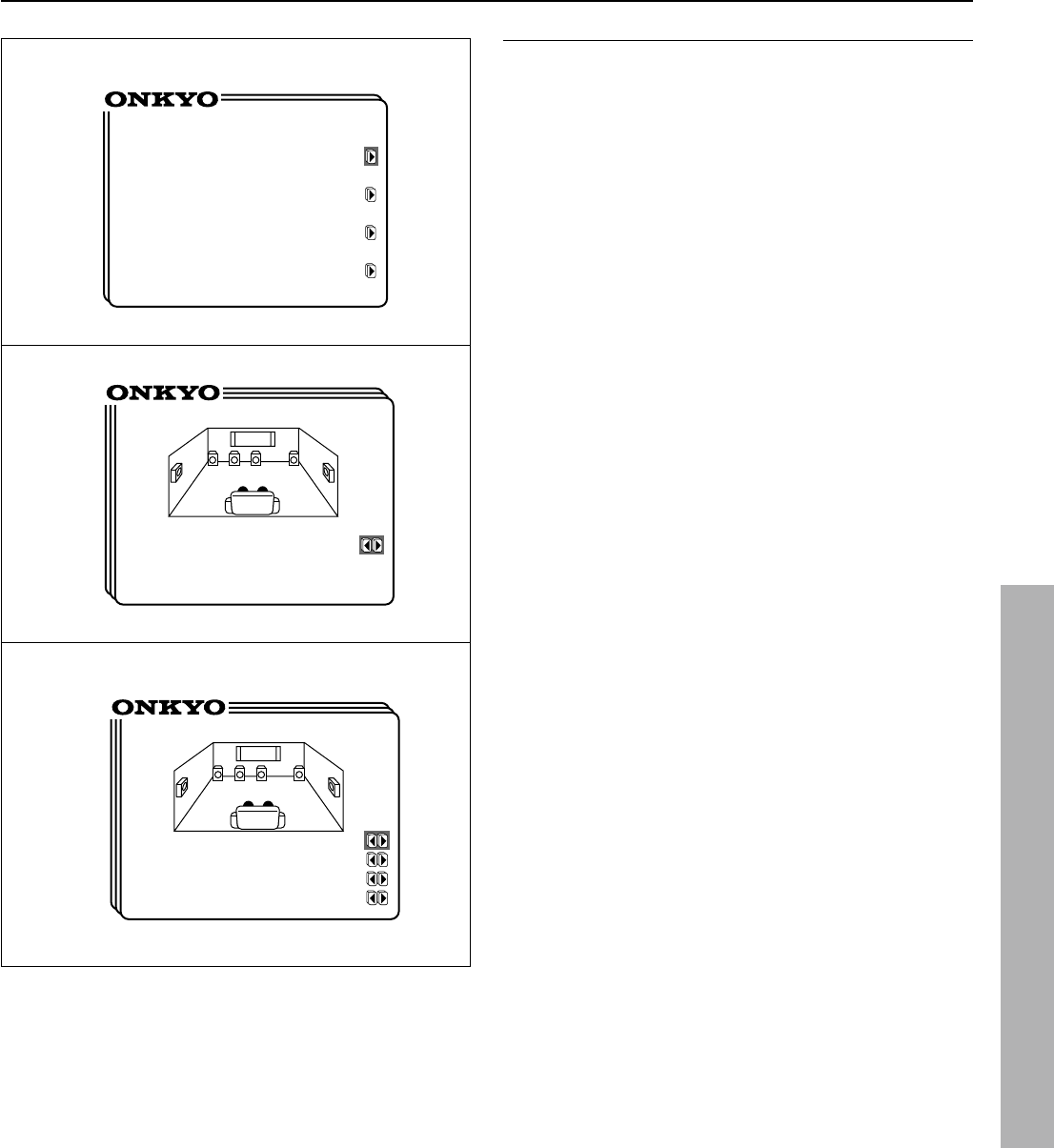
Input Selector screen (page 27,32)
Rec Selector screen (page 45)
Listening Mode Setup screen (page 38)
Speaker Setup screen (page 19)
Screen Setup screen (See the previous page.)
OSD screens
or
Select the input source (page 27).
Perform digital input setting (page 29).
Assign a video input source (page 40).
Perform IntelliVolume setting (page 43).
Set the listening mode (page 36).
Set the speaker configuration (page 19).
Set the speaker distance (page 20).
Set the speaker output level (page 21).
Set the bass peak level (page 23).
Set the background color.
Set the superimpose mode.
Set the simultaneous display mode.
Set the display position of characters.
Set the listening mode parameters
(page 38,39).
Select the audio recording source (page 45).
18
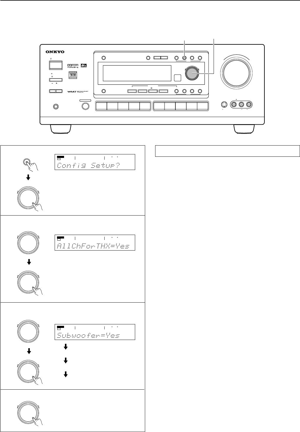
Setting the speaker configuration
Setting the speaker configuration parameters
Using the SMART SCAN CONTROLLER, you can easily set the
speaker configuration. Turn it to select the parameter and press it to
go to the next item.
1.Press the SP/SYS SETUP button.
“Config Setup?” appears. Then Press the SMART SCAN CON-
TROLLER.
2.For the TX-DS676, go to the next step.
For the TX-DS777, “All Ch For THX” appears.
Set “Yes” or “No.”
Yes:Your system is a THX speaker system.
(The following steps are unnecessary.)
No :Your system is a non-THX speaker system.
Press the SMART SCAN CONTROLLER.
3.Set whether or not a subwoofer is connected.
Yes:A subwoofer is connected.
No:A subwoofer is NOT connected.
Press the SMART SCAN CONTROLLER.
4.Select the size of your front speakers.
Large:Large front speakers are used.
Small:Small front speakers are used.
Press the SMART SCAN CONTROLLER.
5.Select the size of your center speaker.
Large:A large center speaker is used.
Small:A small center speaker is used.
None:A center speaker is NOT used.
Press the SMART SCAN CONTROLLER.
6.Select the size of your surround speakers.
Large:Large surround speakers are used.
Small:Small surround speakers are used.
None:Surround speakers are NOT used.
7.Press the SMART SCAN CONTROLLER.
This completes the speaker configuration setup.
1
2
3 ~ 6
SMART SCAN CONTROLLER
SP/SYS SETUP button
Perform this setup before using the unit.
MASTER VOLUME
STANDBY/ON
PHONES
VIDEO CAM INPUT/4VIDEO
VIDEOAUDIOLR
(
MONO
)
SVIDEO
STAND
-
BY
AV
RECEIVER
TX-DS
777
POWER
OFF
ON
A SPEAKERS B
TI CH
INPUTMUL
FM
AMPHONOC
D
TAPEVIDEO-1
DVD
VIDEO-4
VIDEO-3
VIDEO-2
D
O
W
N
U
P
FM MUTE/
MODE
CHARACTER/
MEMORY
SP/SYS
SETUP
SMART SCAN
CONTROLLER
MODE
AUDIO
ADJUSTMENT
BASS/
TREBLE
DISPLAYDSPREC OUT
PRESET/MODE ADJ
PUSH TO ENTER
DOWN TUNING UP
THX /DTS
SURROUNDMODE
LISTENING MODE
STEREODIRECT
DIGITAL/
ANALOG
CH LEVEL
DIMMER
SP/SYS
SETUP
PRESET/MODE ADJ
PUSH TO ENTER
SPEAKERS
A
TUNED
AUTO
SPEAKERS
A
TUNED
AUTO
SPEAKERS
AFM STEREOAUTO
TUNED
Front
Center
Surround
7
PRESET/MODE ADJ
PUSH TO ENTER
PRESET/MODE ADJ
PUSH TO ENTER
PRESET/MODE ADJ
PUSH TO ENTER
PRESET/MODE ADJ
PUSH TO ENTER
PRESET/MODE ADJ
PUSH TO ENTER
TX-DS777 only
(The layout of buttons, switches, and other controls on the front
panel may vary depending where the unit is purchased.)
19
Setting the speaker configuration
•Using the on-screen display
1.Press the OSD MENU button.
2.Select “Speaker Setup” and then press the right edge of the
ENTER/Cursor button.
3.Select “Config Setup” and then press the right edge of the
ENTER/Cursor button.
4.For the TX-DS676, go to the next step.
For the TX-DS777, the display shows “All Channel For THX
Speakers.”
Select “Yes” and then press the center of the ENTER/Cursor
button. This sets all the connected speakers to THX
speakers.(The following steps are unnecessary.)
Select “No” and then press the center of the ENTER/Cursor but-
ton to go to the next step.
5.Press the upper or lower edge of the ENTER/Cursor button
to set each item and then press the right or left edge of the
button to set a parameter
Subwoofer: Set whether or not a subwoofer is connected.
Yes:A subwoofer is connected.
No:A subwoofer is NOT connected.
Front : Select the size of your front speakers.
Large: Large front speakers are used.
Small: Small front speakers are used.
Center : Select the size of your center speaker.
Large:A large center speaker is used.
Small:A small center speaker is used.
None:A center speaker is NOT used.
Surround : Select the size of your surround speakers.
Large:Large surround speakers are used.
Small:Small surround speakers are used.
None:Surround speakers are NOT used.
6.Press the center of the ENTER/Cursor button, or press the
EXIT button, to exit the setup mode.
3
4
5
** Speaker Setup **
Config Setup
Distance Setup
Level Setup
Bass Peak Setup
* Config Setup *
All Channel For
THX Speakers =No
* Config Setup *
Subwoofer=Yes
Front=Small
Center=Small
Surround=Small
20
PRESET/MODE ADJ
PUSH TO ENTER
SP/SYS
SETUP
Setting the speaker distance
Setting the distance from each speaker to the
listening position
(Loudspeaker Position Time Synchronization*)
Select a value that is closest to the actual distance between each
speaker and the listening position.
Using the SMART SCAN CONTROLLER, you can easily set the
speaker configuration. Turn it to select the setting and press it to go
to the next item.
For each speaker, you can set a distance of 0.3 meter to 9.0 meters
(or 1 foot to 30 feet) in increments of 30 cm (1 foot).
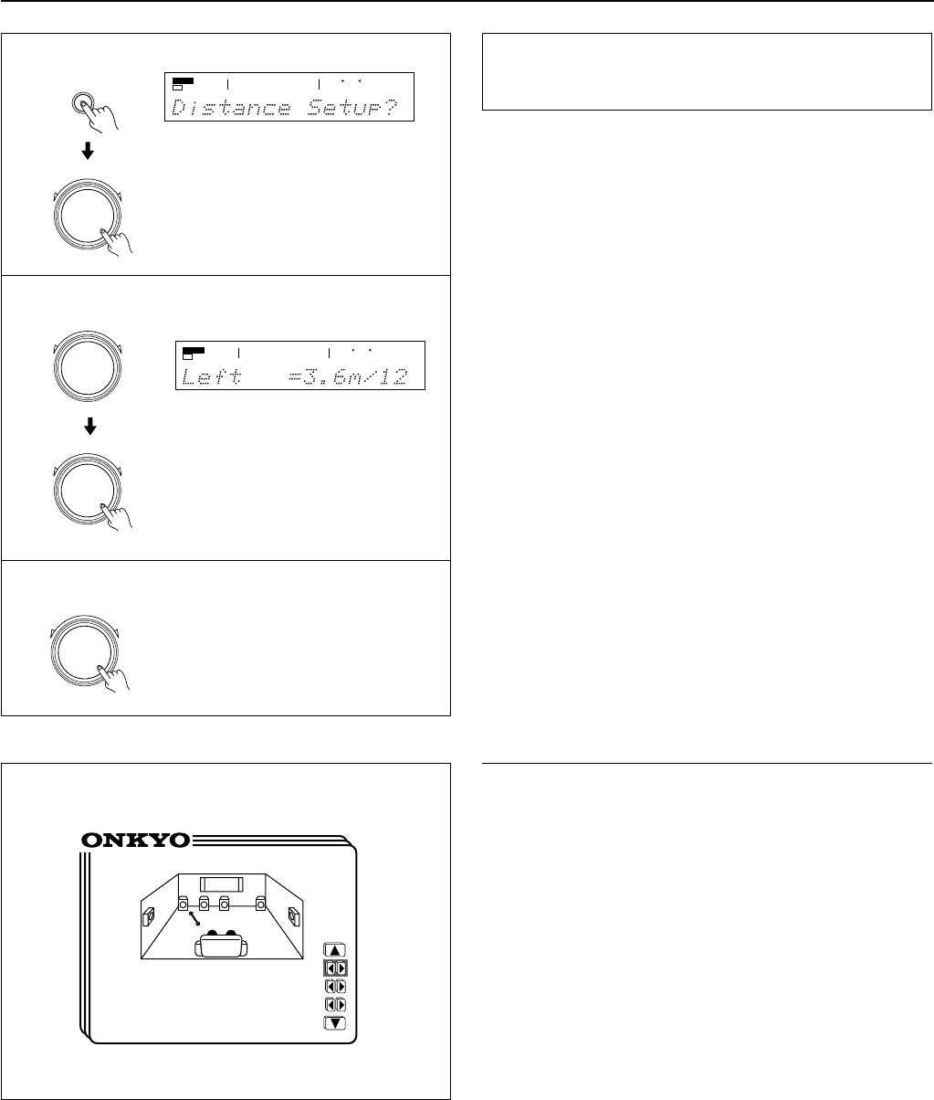
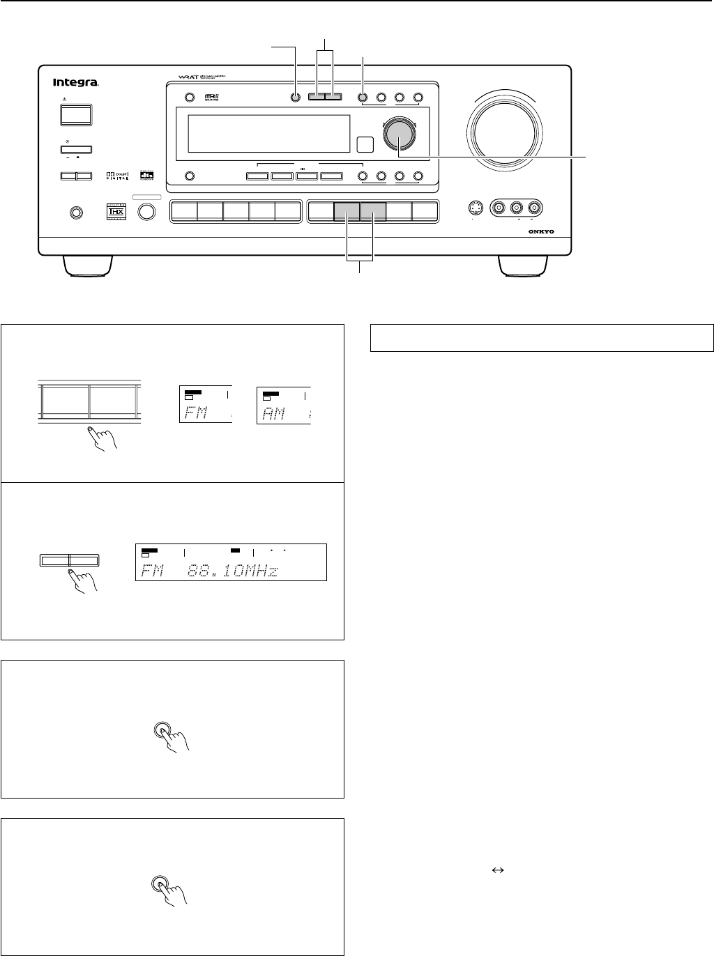
1.Press the SP/SYS SETUP button repeatedly until “Distance
Setup ?” appears.
Press the SMART SCAN CONTROLLER.
2.“Left=” appears. Set the distance from the left front
speaker.
Press the SMART SCAN CONTROLLER.
3.“Center=” appears. Set the distance from the center
speaker.
Press the SMART SCAN CONTROLLER.
4.“Right=” appears. Set the distance from the Right front
speaker.
Press the SMART SCAN CONTROLLER.
5.“R-Sur=” appears. Set the distance from the Right surround
speaker.
Press the SMART SCAN CONTROLLER.
6.“L-Sur=” appears Set the distance from the left surround
speaker.
Press the SMART SCAN CONTROLLER.
7.“SW=” appears. Set the distance from the subwoofer.
8.Press the SMART SCAN CONTROLLER.
The speaker distance setup has been completed.
*Loudspeaker Position Time Synchronization is a registered trademark of
Lucasfilm LTD.
1
2 ~ 7
•Using the on-screen display
1.Press the OSD MENU button.
2.Select “Speaker Setup” and then press the right edge of the
ENTER/Cursor button.
3.Select “Distance Setup” and then press the right edge of the
ENTER/Cursor button.
You can now set the distance from each speaker.
(When the cursor is on “Right,” you can press the lower edge of
the ENTER/Cursor button to display additional items.)
Select a value that is closest to the actual distance. For each
speaker, you can set a distance of 0.3 meter to 9.0 meters (or 1
foot to 30 feet) in increments of 30 cm (I foot).
Left : Left front speaker
Center : Center speaker
Right : Right front speaker
R-Sur : Right surround speaker
L-Sur : Left surround speaker
Subwoofer : Subwoofer
4.Press the center of the ENTER/Cursor button, or press the
EXIT button, to exit the setup mode.
* Distance Setup *
Left=3.6m/12ft
Center=3.6m/12ft
Right=3.6m/12ft
(R-Sur=2.1m/ 7ft)
SPEAKERS
A
AUTO
TUNED
PRESET/MODE ADJ
PUSH TO ENTER
PRESET/MODE ADJ
PUSH TO ENTER
PRESET/MODE ADJ
PUSH TO ENTER
SPEAKERS
A
PCM DIGITALFM STEREO
TUNED
AUTO
ft
8
21
2
Using the test tone to adjust the speaker output
levels
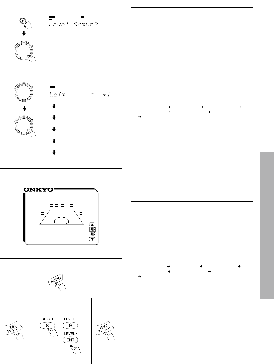
1.Press the SP/SYS SETUP button repeatedly until
“Level Setup?” appears.
Press the SMART SCAN CONTROLLER.
The display shows “Left.”
2.Rotate clockwise or counterclockwise the SMART SCAN
CONTROLLER to adjust the speaker output level.
You can adjust the output level of each speaker in the range of
12 to +12 dB, except for the subwoofer whose adjustment range
is -30 to +10 dB.
Press the SMART SCAN CONTROLLER.
You hear a test tone (pink noise) from the left front speaker.
Each time you press the SMART SCAN CONTROLLER, the
speaker that produces a test tone changes as below. Set the out-
put level of each speaker by rotating the SMART SCAN CON-
TROLLER so that you can hear the same level of test tone at the
listening position.
Left (Left front)
Center (Center) Right (Right front)R-Sur
(Right surround)
L-Sur(Left surround)Subwoofer (Subwoofer)
Left
Notes:
•In order to correctly set the output levels, use a hand-held Sound
Pressure Level meter (SPL), set to C-Weighting and Slow aver-
aging. A Radio Shack
®
SPL meter (catalogue number 330-
2055) or equivalent can be used. Using the internal channel
noise generators, set each channel so that you read 75 dB SPL
from each channel.
•SPEAKER B, when selected, will be deselected automatically
as soon as the test tone starts sounding. The Test Tone function
is not available when the headphones are connected or when
MULTI CH INPUT is selected.
•The test tone will not be output from the speaker that has been set to
"No" in the configuration setup explained on the page 18,19.
•If the speaker level is set to +1dB or higher , the maximum level indi-
cated on the display will change if you raise the volume level.
Setting the speaker Level
•Using the on-screen display
1.Press the OSD MENU button.
2.Select “Speaker Setup” and then press the right edge of the
ENTER/Cursor button.
3.Select “Level Setup” and then press the right edge of the
ENTER/Cursor button.
The Level Setup screen appears and a test tone (pink noise) is
output from the left front speaker. You can change the speaker
that outputs the test tone in the following sequence.(When the
cursor is on “Center,” you can press the lower edge of the EN-
TER/Cursor button to display additional items.)
Left (Left front)
Center (Center)Right (Right front) R-Sur
(Right surround)
L-Sur (Left surround)Subwoofer (Subwoofer)
Left.
4.Set the output level of each speaker so that you can hear the
same level of test tone at the listening position.
You can adjust the output level of each speaker in the range of -
12 to +12 dB, except for the subwoofer whose adjustment range
is -30 to +10 dB.
5.Press the center of the ENTER/Cursor button, or press the
EXIT button, to exit the setup mode.
* Level Setup *
Left= +1dB
Center= 0dB
(Right= 0dB)
SP/SYS
SETUP
1
PRESET/MODE ADJ
PUSH TO ENTER
PRESET/MODE ADJ
PUSH TO ENTER
PRESET/MODE ADJ
PUSH TO ENTER
SPEAKERS
A
PCM DIGITAL
STEREO
db
Center
Right
R-Sur
L-Sur
SW
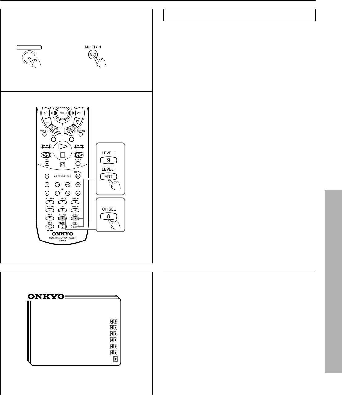
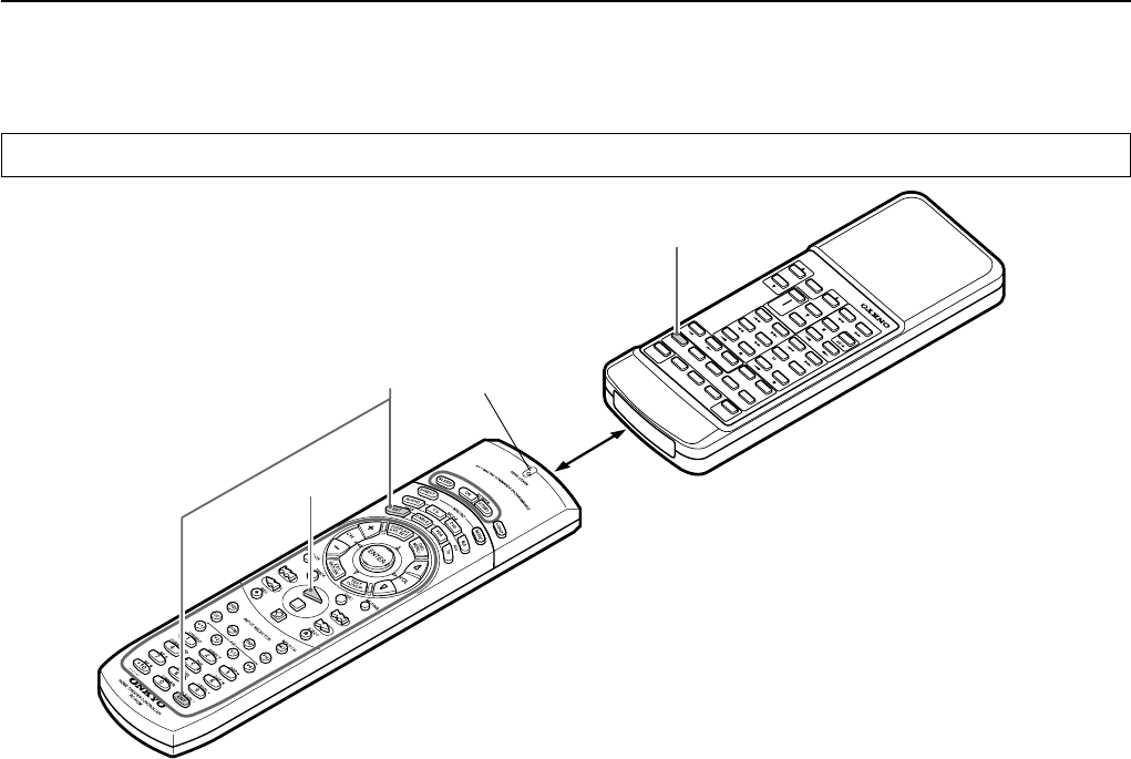
•Using Test button on the remote controller
1.Press the MODE AUDIO button.
2.Press the TEST button.
Left front speaker produces the test tone (pink noise).
3.To adjust the level of each speaker,press the CH SEL, but-
ton to select a speaker and press the LEVEL +/- buttons to
raise or lower the level.
4.Press rhe TEST button to complete adjustment.
1
234
SPEAKERS
A
DSP
22
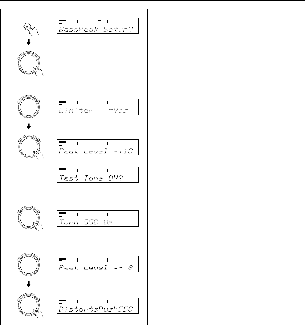
Setting the bass peak level
(Bass Peak Level Manager* TX-DS777 only)
To prevent damage to your subwoofer, you can set the bass peak
level the subwoofer can reproduce.
If your system does not include any subwoofer, this will set the bass
peak level your Front speakers can reproduce.
1.Press the SP/SYS SETUP button repeatedly until
“Bass Peak Setup?” appears. Then Press the SMART SCAN
CONTROLLER.
“Limiter =”appears and You are now in the bass peak level set-
ting mode.
2.Rotate the SMART SCAN CONTROLLER to select “Yes”
or “No.”
If you select “Yes” and then press the SMART SCAN CON-
TROLLER, the display will show the current peak level fol-
lowed by “Test Tone ON?.”
3.Press the SMART SCAN CONTROLLER.
The test tone is output and “Turn SSC Up” appears.
4.Gently rotate the SMART SCAN CONTROLLER clockwise
and, just before sound is distorted, press the SMART SCAN
CONTROLLER.
If you do not press the SMART SCAN CONTROLLER, “Dis-
torts Push SSC” appears.
Note:
•Allowing the speakers to produce distorted sound for a long
time may cause damage to the speakers.
•To disable the bass peak level limiter, select “No” in step 2.
*Bass Peak Level Manager is a registered trademark of Lucasfilm LTD.
Setting the Speaker level
1
2
3
4
SP/SYS
SETUP
PRESET/MODE ADJ
PUSH TO ENTER
PRESET/MODE ADJ
PUSH TO ENTER
PRESET/MODE ADJ
PUSH TO ENTER
PRESET/MODE ADJ
PUSH TO ENTER
PRESET/MODE ADJ
PUSH TO ENTER
SPEAKERS
A
DSP
SPEAKERS
A
SPEAKERS
A
SPEAKERS
A
SPEAKERS
A
SPEAKERS
A
db
SPEAKERS
A
db
PRESET/MODE ADJ
PUSH TO ENTER
23
PRESET/MODE ADJ
PUSH TO ENTER
PRESET/MODE ADJ
PUSH TO ENTER
•Using the on-screen display
1.Press the OSD MENU button.
2.Select “Speaker Setup” and then press the right edge of the
ENTER/Cursor button.
3.Select “Bass Peak Setup” and then press the right edge of the
Libble takes abuse of its services very seriously. We're committed to dealing with such abuse according to the laws in your country of residence. When you submit a report, we'll investigate it and take the appropriate action. We'll get back to you only if we require additional details or have more information to share.
Product:
Forumrules
To achieve meaningful questions, we apply the following rules:
First, read the manual;
Check if your question has been asked previously;
Try to ask your question as clearly as possible;
Did you already try to solve the problem? Please mention this;
Is your problem solved by a visitor then let him/her know in this forum;
To give a response to a question or answer, do not use this form but click on the button 'reply to this question';
Your question will be posted here and emailed to our subscribers. Therefore, avoid filling in personal details.
Register
Register getting emails for Onkyo TX-DS777 at:
new questions and answers
new manuals
You will receive an email to register for one or both of the options.
Get your user manual by e-mail
Enter your email address to receive the manual of Onkyo TX-DS777 in the language / languages: English as an attachment in your email.
The manual is 2,69 mb in size.
You will receive the manual in your email within minutes. If you have not received an email, then probably have entered the wrong email address or your mailbox is too full. In addition, it may be that your ISP may have a maximum size for emails to receive.
The manual is sent by email. Check your email
If you have not received an email with the manual within fifteen minutes, it may be that you have a entered a wrong email address or that your ISP has set a maximum size to receive email that is smaller than the size of the manual.
The email address you have provided is not correct.
Please check the email address and correct it.
Your question is posted on this page
Would you like to receive an email when new answers and questions are posted? Please enter your email address.