Contents > 4
C
ONTENTS
Preface . . . . . . . . . . . . . . . . . . . . . . . . . . . . . . . . . . . . . . . . . . . . . . . . . . .2
Emergency first aid . . . . . . . . . . . . . . . . . . . . . . . . . . . . . . . . . . . . . . . . . .3
Manufacturer . . . . . . . . . . . . . . . . . . . . . . . . . . . . . . . . . . . . . . . . . . . . . . .3
Importer to the EU/authorised representative. . . . . . . . . . . . . . . . . . . . .3
Environmental information . . . . . . . . . . . . . . . . . . . . . . . . . . . . . . . . . . . .3
Contents . . . . . . . . . . . . . . . . . . . . . . . . . . . . . . . . . . . . . . . . . . . . . . . . . .4
Notes, cautions and warnings . . . . . . . . . . . . . . . . . . . . . . . . . . . . . . . . . .6
About this guide . . . . . . . . . . . . . . . . . . . . . . . . . . . . . . . . . . . . . . . . . . . .7
Documentation suite . . . . . . . . . . . . . . . . . . . . . . . . . . . . . . . . . . . . . . . 7
On-line usage . . . . . . . . . . . . . . . . . . . . . . . . . . . . . . . . . . . . . . . . . . . . 8
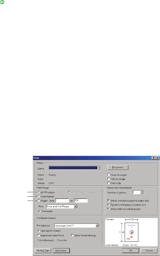
Printing pages. . . . . . . . . . . . . . . . . . . . . . . . . . . . . . . . . . . . . . . . . . . . 8
Introduction . . . . . . . . . . . . . . . . . . . . . . . . . . . . . . . . . . . . . . . . . . . . . . .9
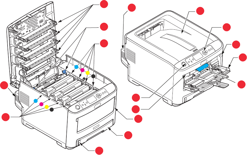
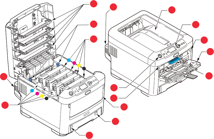
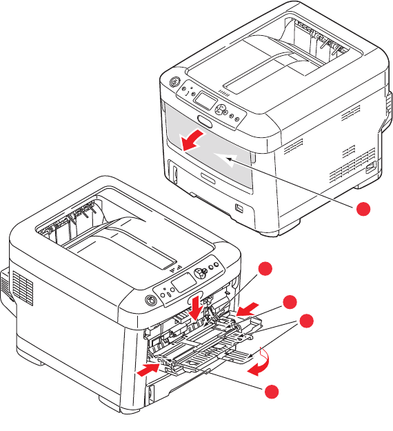
Printer overview . . . . . . . . . . . . . . . . . . . . . . . . . . . . . . . . . . . . . . . . . .10
Front view . . . . . . . . . . . . . . . . . . . . . . . . . . . . . . . . . . . . . . . . . . . .10
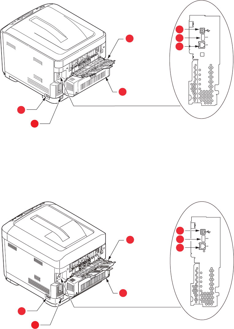
Rear view . . . . . . . . . . . . . . . . . . . . . . . . . . . . . . . . . . . . . . . . . . . . .12
Changing the display language . . . . . . . . . . . . . . . . . . . . . . . . . . . . . . . .13
Getting started . . . . . . . . . . . . . . . . . . . . . . . . . . . . . . . . . . . . . . . . . . .13
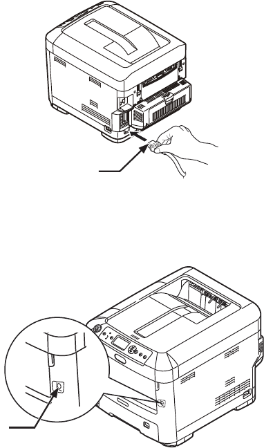
Turning On the Power . . . . . . . . . . . . . . . . . . . . . . . . . . . . . . . . . . . .13
Turning Off the Power . . . . . . . . . . . . . . . . . . . . . . . . . . . . . . . . . . . .14
Power saving mode . . . . . . . . . . . . . . . . . . . . . . . . . . . . . . . . . . . . . .14
Paper recommendations . . . . . . . . . . . . . . . . . . . . . . . . . . . . . . . . . . . . .15
Cassette trays. . . . . . . . . . . . . . . . . . . . . . . . . . . . . . . . . . . . . . . . . . . .16
Multi purpose tray . . . . . . . . . . . . . . . . . . . . . . . . . . . . . . . . . . . . . . . . .16
Output tray (face down). . . . . . . . . . . . . . . . . . . . . . . . . . . . . . . . . . . . .16
Rear output tray (face up) . . . . . . . . . . . . . . . . . . . . . . . . . . . . . . . . . . .16
Duplex unit. . . . . . . . . . . . . . . . . . . . . . . . . . . . . . . . . . . . . . . . . . . . . .17
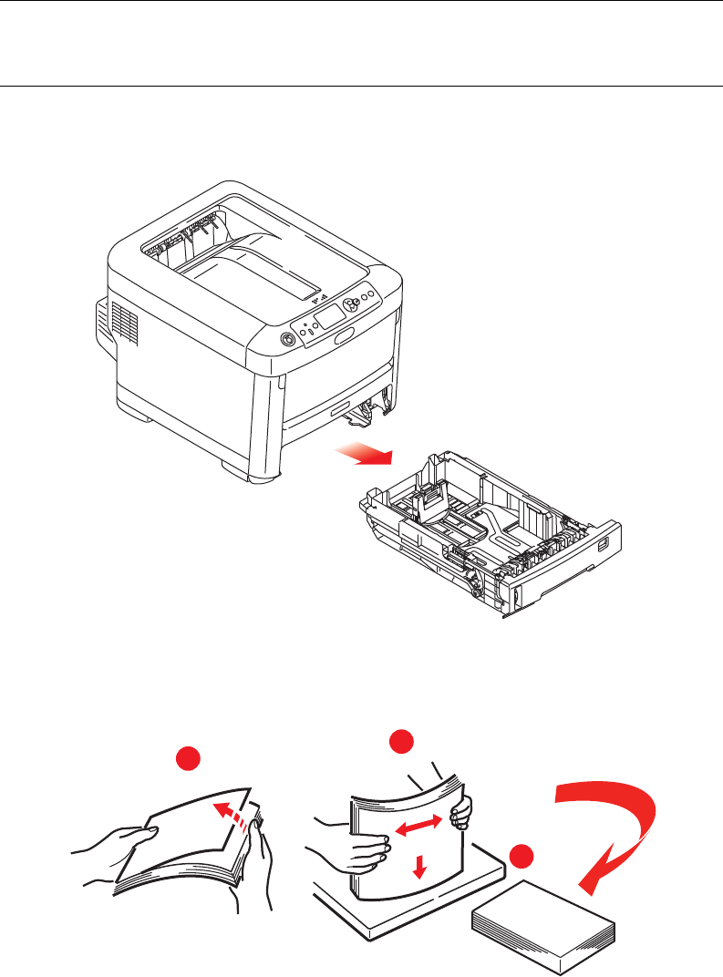
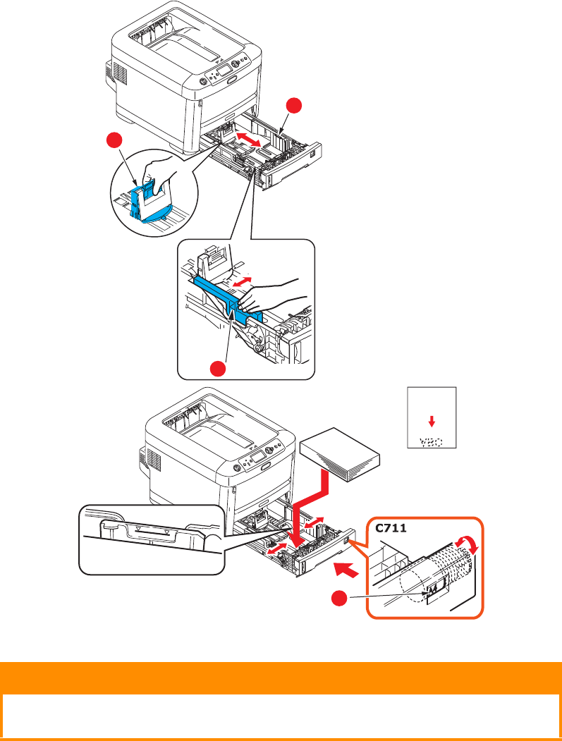
Loading paper . . . . . . . . . . . . . . . . . . . . . . . . . . . . . . . . . . . . . . . . . . . . .18
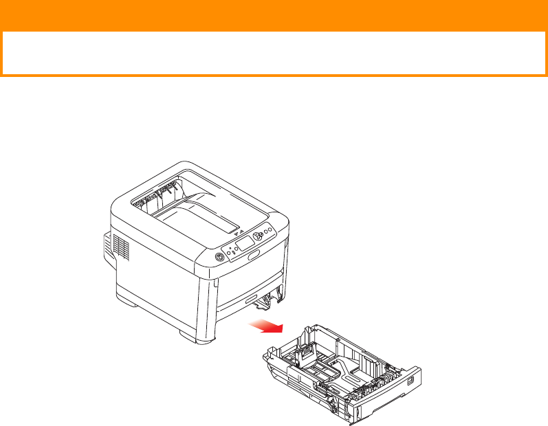
Cassette trays. . . . . . . . . . . . . . . . . . . . . . . . . . . . . . . . . . . . . . . . . . . .18
Multi purpose tray . . . . . . . . . . . . . . . . . . . . . . . . . . . . . . . . . . . . . . . . .21
Operation . . . . . . . . . . . . . . . . . . . . . . . . . . . . . . . . . . . . . . . . . . . . . . . .22
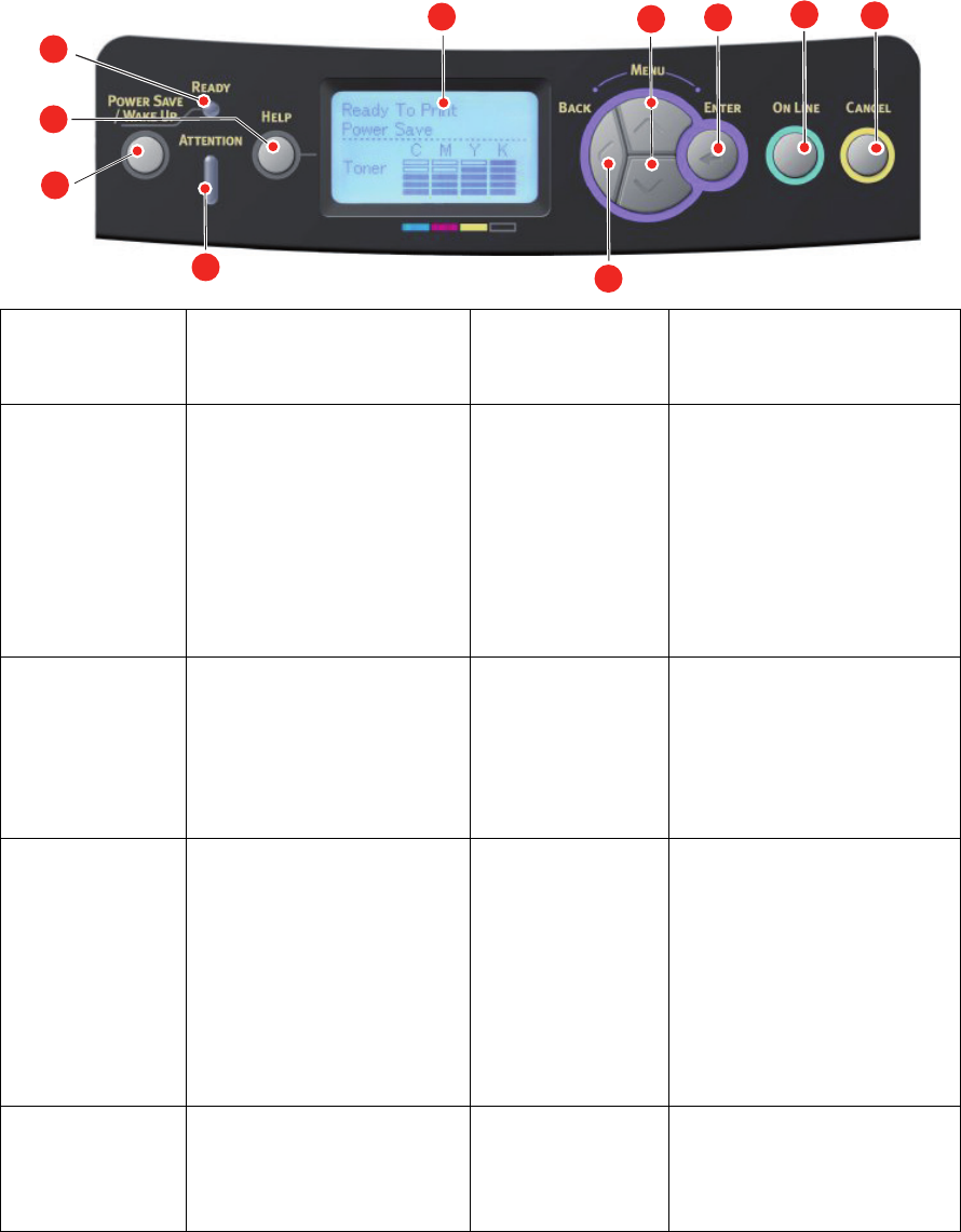
Menu functions . . . . . . . . . . . . . . . . . . . . . . . . . . . . . . . . . . . . . . . . . . . .23
Operator panel: . . . . . . . . . . . . . . . . . . . . . . . . . . . . . . . . . . . . . . . . . .23
How to change the settings - user . . . . . . . . . . . . . . . . . . . . . . . . . . . . . .24
How to change the settings - administrator . . . . . . . . . . . . . . . . . . . . . . .24
Print From USB Memory . . . . . . . . . . . . . . . . . . . . . . . . . . . . . . . . . . .25
Print . . . . . . . . . . . . . . . . . . . . . . . . . . . . . . . . . . . . . . . . . . . . . . . .25
Configuration menu . . . . . . . . . . . . . . . . . . . . . . . . . . . . . . . . . . . . . .26
Print information menu . . . . . . . . . . . . . . . . . . . . . . . . . . . . . . . . . . .28
Menus . . . . . . . . . . . . . . . . . . . . . . . . . . . . . . . . . . . . . . . . . . . . . . .29
Admin setup . . . . . . . . . . . . . . . . . . . . . . . . . . . . . . . . . . . . . . . . . . .33
Print Statistics. . . . . . . . . . . . . . . . . . . . . . . . . . . . . . . . . . . . . . . . . .46
Calibration . . . . . . . . . . . . . . . . . . . . . . . . . . . . . . . . . . . . . . . . . . . .47
Google Cloud Print. . . . . . . . . . . . . . . . . . . . . . . . . . . . . . . . . . . . . . .48
Wireless(Infrastructure) Setting . . . . . . . . . . . . . . . . . . . . . . . . . . . . .49
Wireless(AP Mode) Setting . . . . . . . . . . . . . . . . . . . . . . . . . . . . . . . . .50
Boot menu . . . . . . . . . . . . . . . . . . . . . . . . . . . . . . . . . . . . . . . . . . . .51
Maintenance . . . . . . . . . . . . . . . . . . . . . . . . . . . . . . . . . . . . . . . . . . . . . .53
Replacing consumable items . . . . . . . . . . . . . . . . . . . . . . . . . . . . . . . . . .53
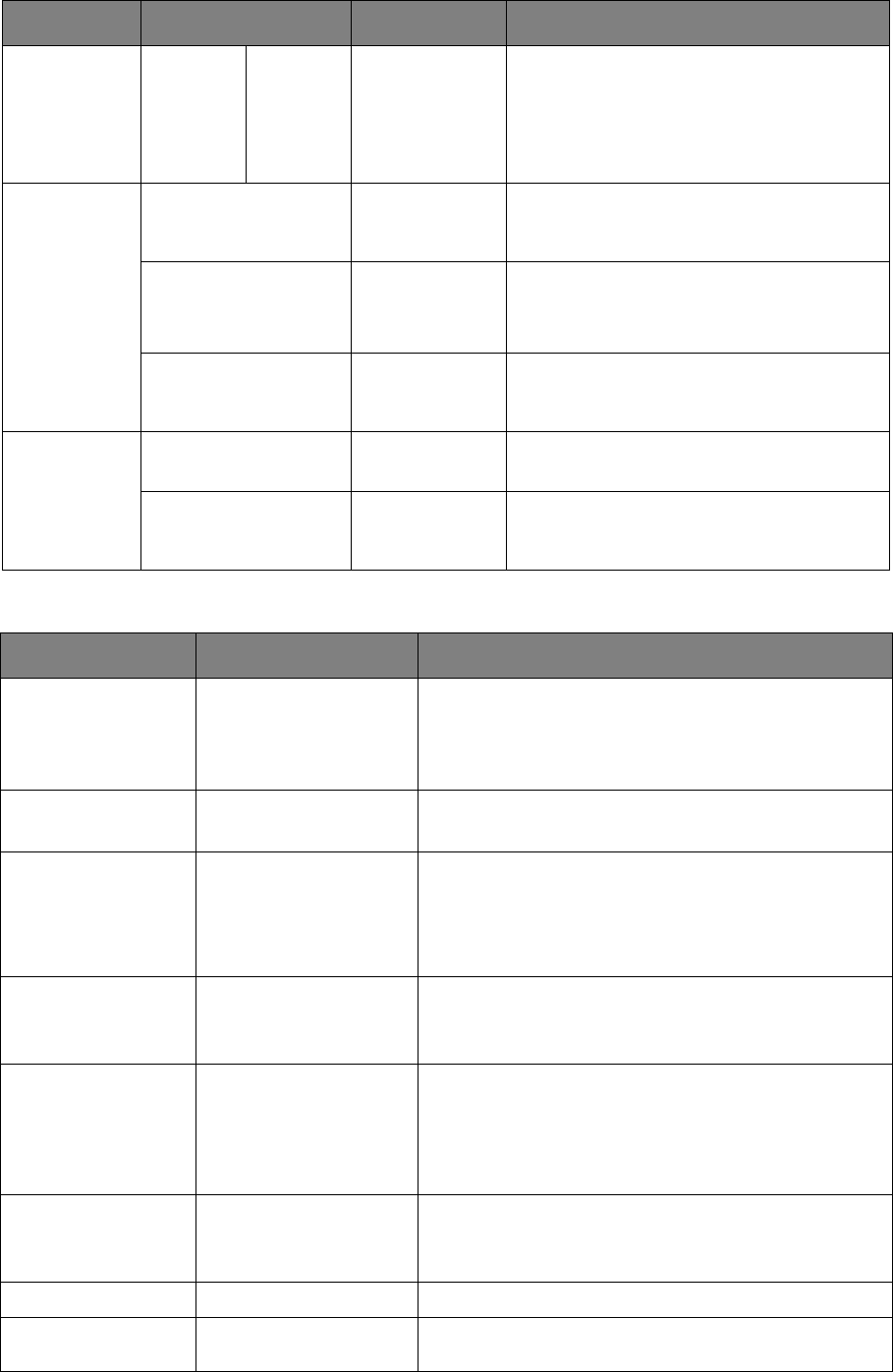
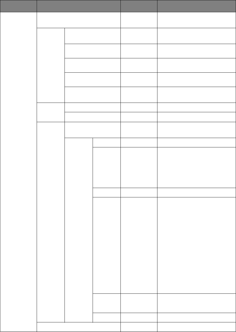
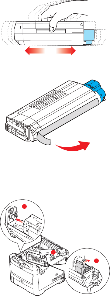
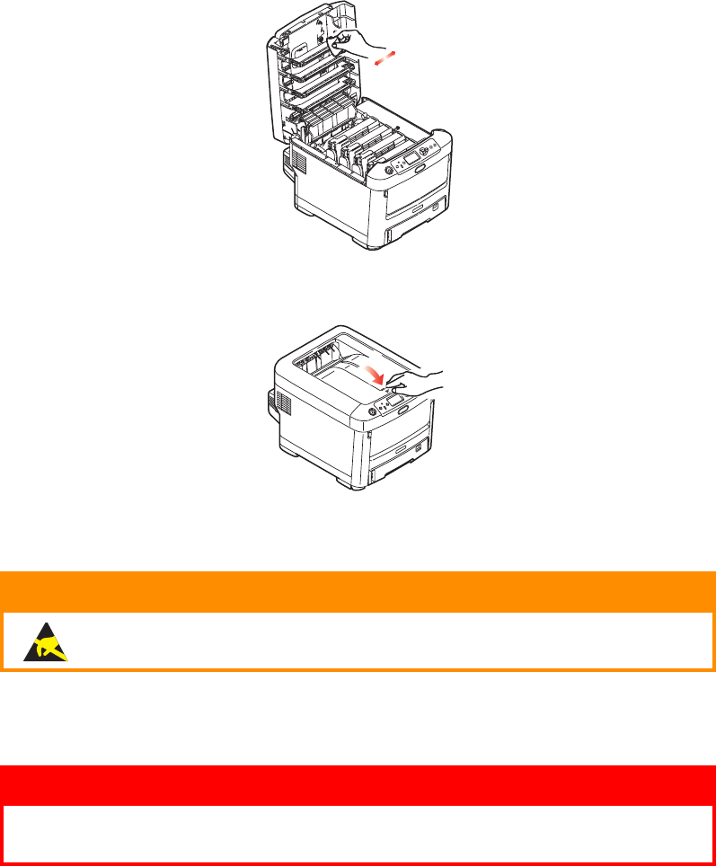
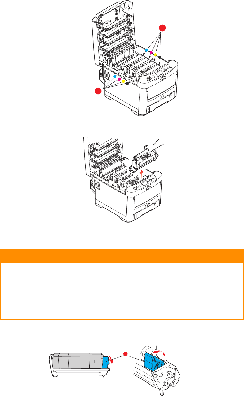
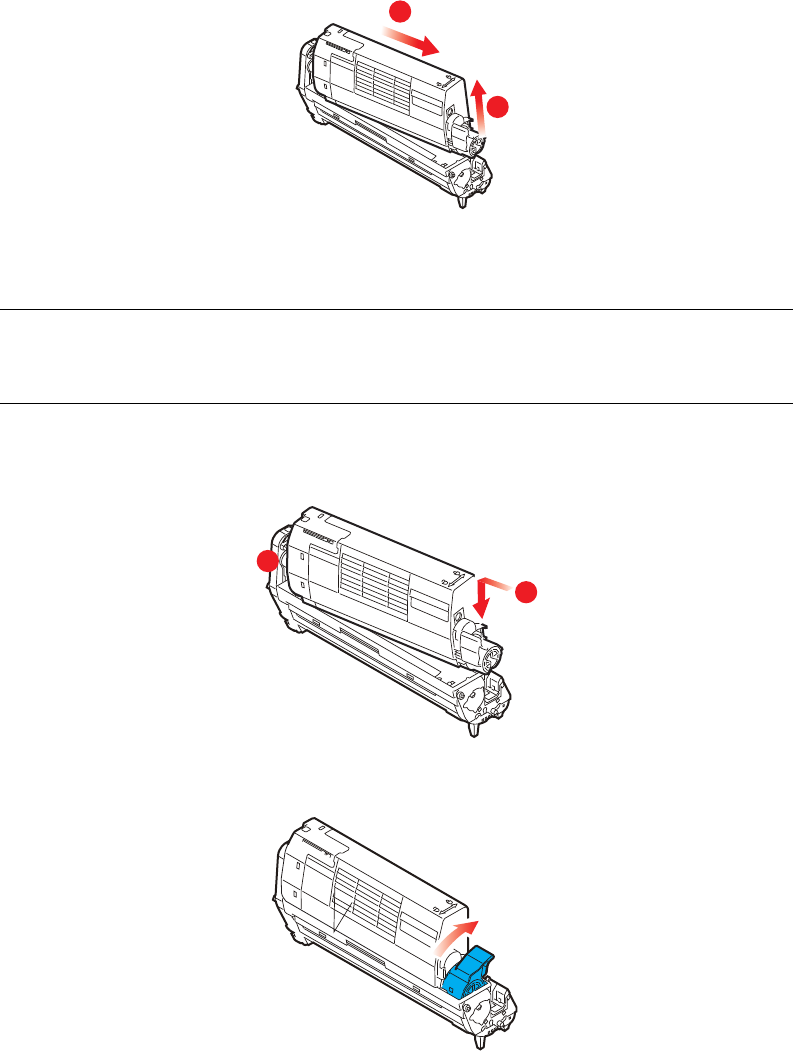
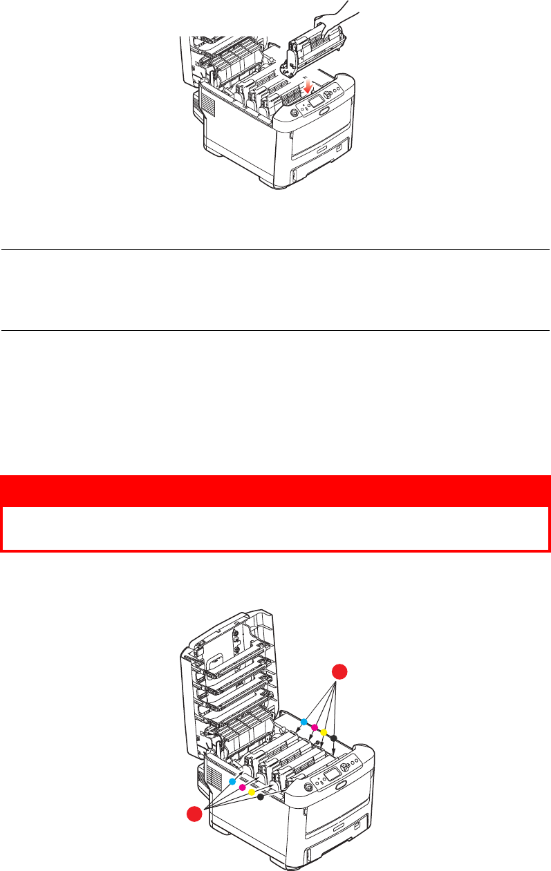
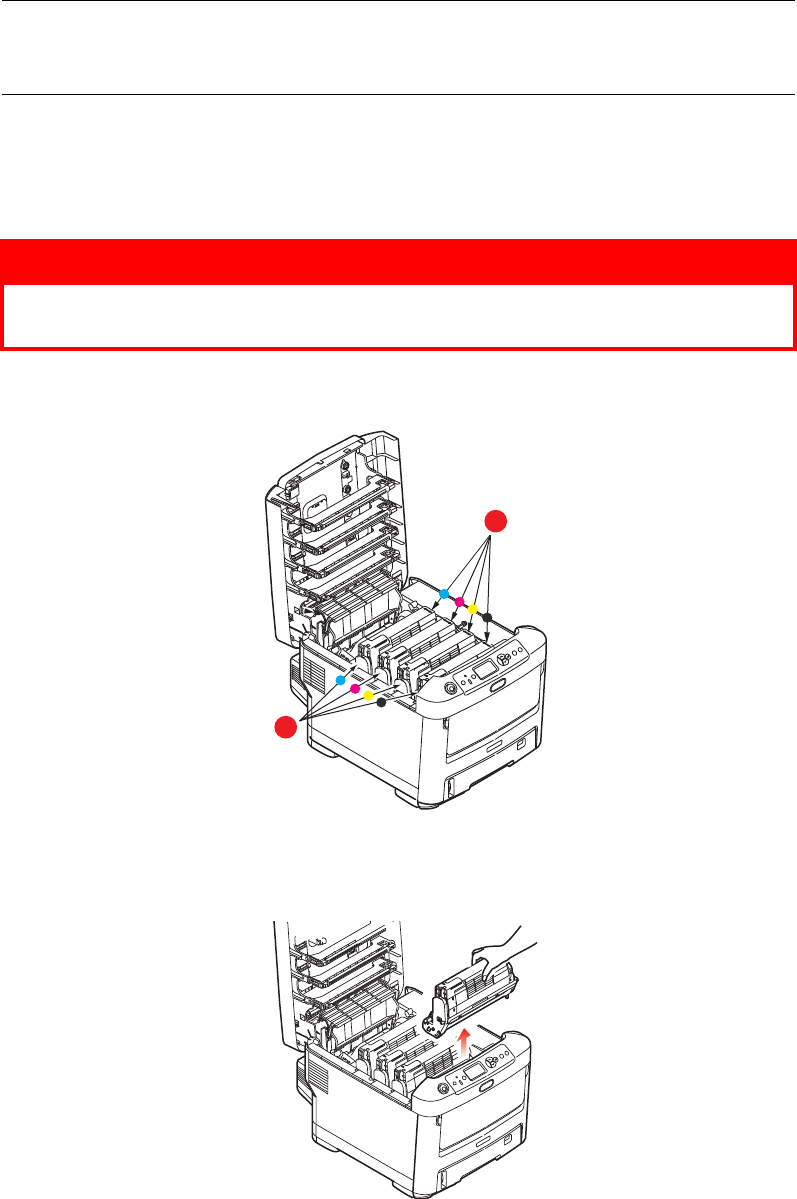
Toner cartridge replacement . . . . . . . . . . . . . . . . . . . . . . . . . . . . . . . .53
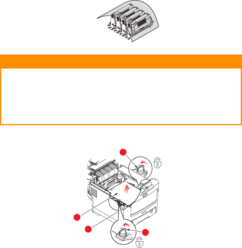
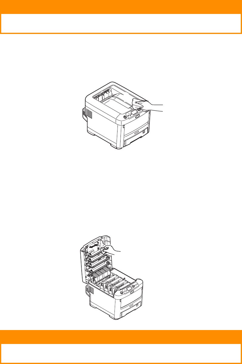
Image drum replacement . . . . . . . . . . . . . . . . . . . . . . . . . . . . . . . . . .56
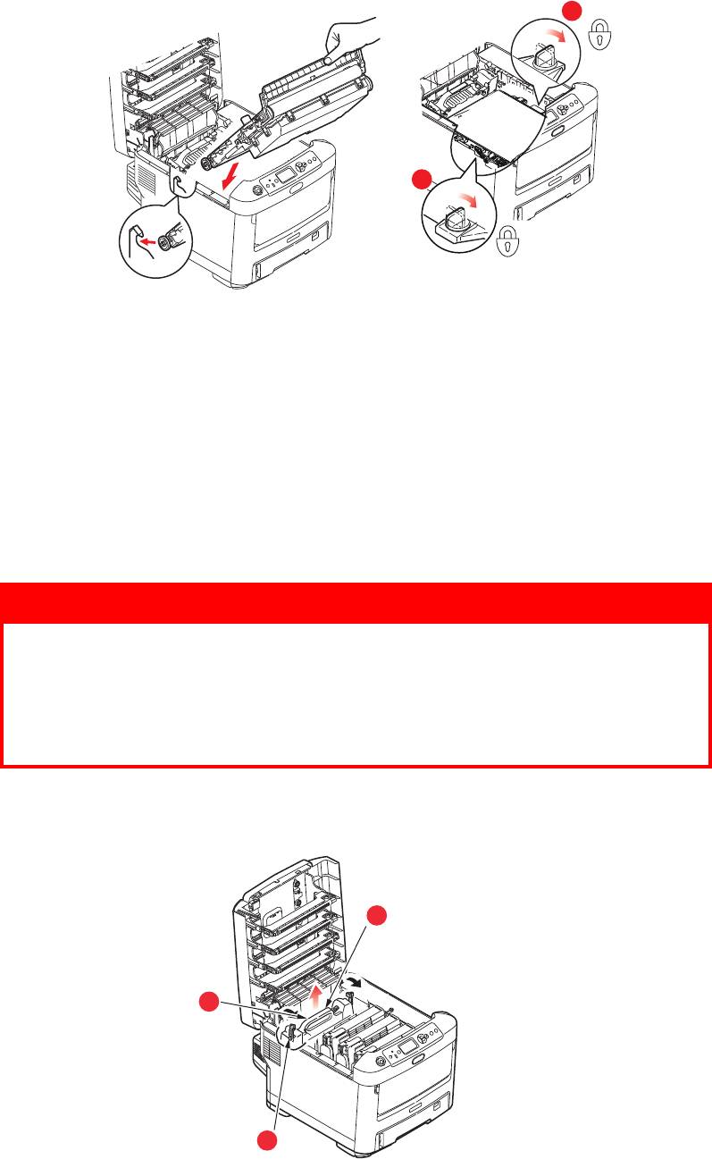
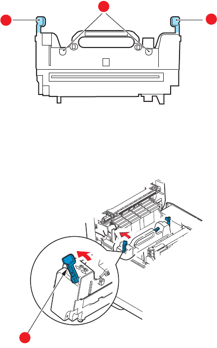
Replacing the transfer belt unit . . . . . . . . . . . . . . . . . . . . . . . . . . . . . .59
Fuser replacement. . . . . . . . . . . . . . . . . . . . . . . . . . . . . . . . . . . . . . .61