Before using for the first time
If you encounter a problem
If you have any questions or if a fault
occurs, please call Customer Service.
(See list of Customer Service
representatives).
When you call, please quote the following:
E-Nr. FD
Enter the relevant numbers into the box
above. The E-Nr. (product no.) and FD
(production date) are shown on the
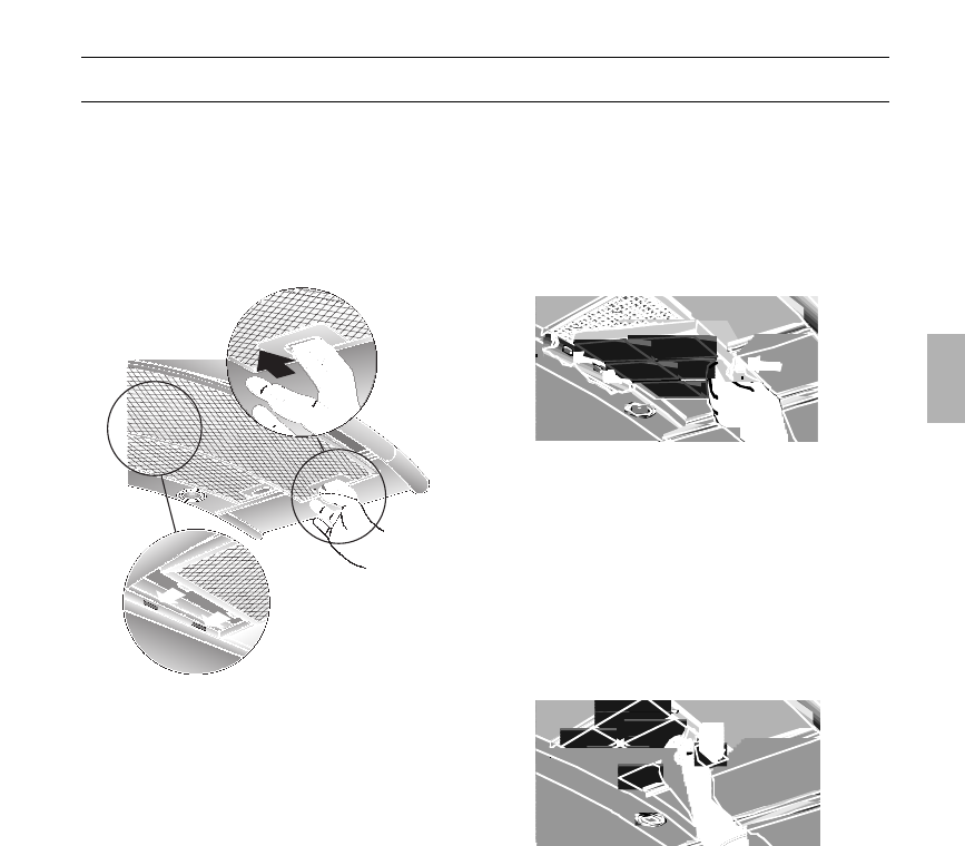
nameplate which can be seen inside the
extractor hood after the filter frame has
been detached.
Important notes:
❑ The Instructions for Use apply to several
versions of this appliance. Accordingly,
you may find descriptions of individual
features that do not apply to your
specific appliance.
❑ This extractor hood complies with all
relevant safety regulations.
Repairs should be carried out by
qualified technicians only.
Improper repairs may put the user at
considerable risk.
❑ Before using your appliance for the first
time, please read these Instructions for
Use carefully. They contain important
information concerning your personal
safety as well as on use and care of the
appliance.
❑ Please retain the operating and
installation instructions for a subsequent
owner.
ṇ Do not use the appliance if damaged.
ṇ The appliance is not intended for use by
young children or infirmed persons
without supervision.
Young children should be supervised to
ensure they do not play with the appliance.
ṇ If the connecting cable for this
appliance is damaged, the cable must be
replaced by the manufacturer or his customer
service or a similarly qualified person in order
to prevent serious injury to the user.
ṇ The appliance may be connected to the
mains by a qualified technician only.
ṇ Dispose of packaging materials
properly (see Installation instructions).
ṇ This extractor hood is designed for
domestic use only.
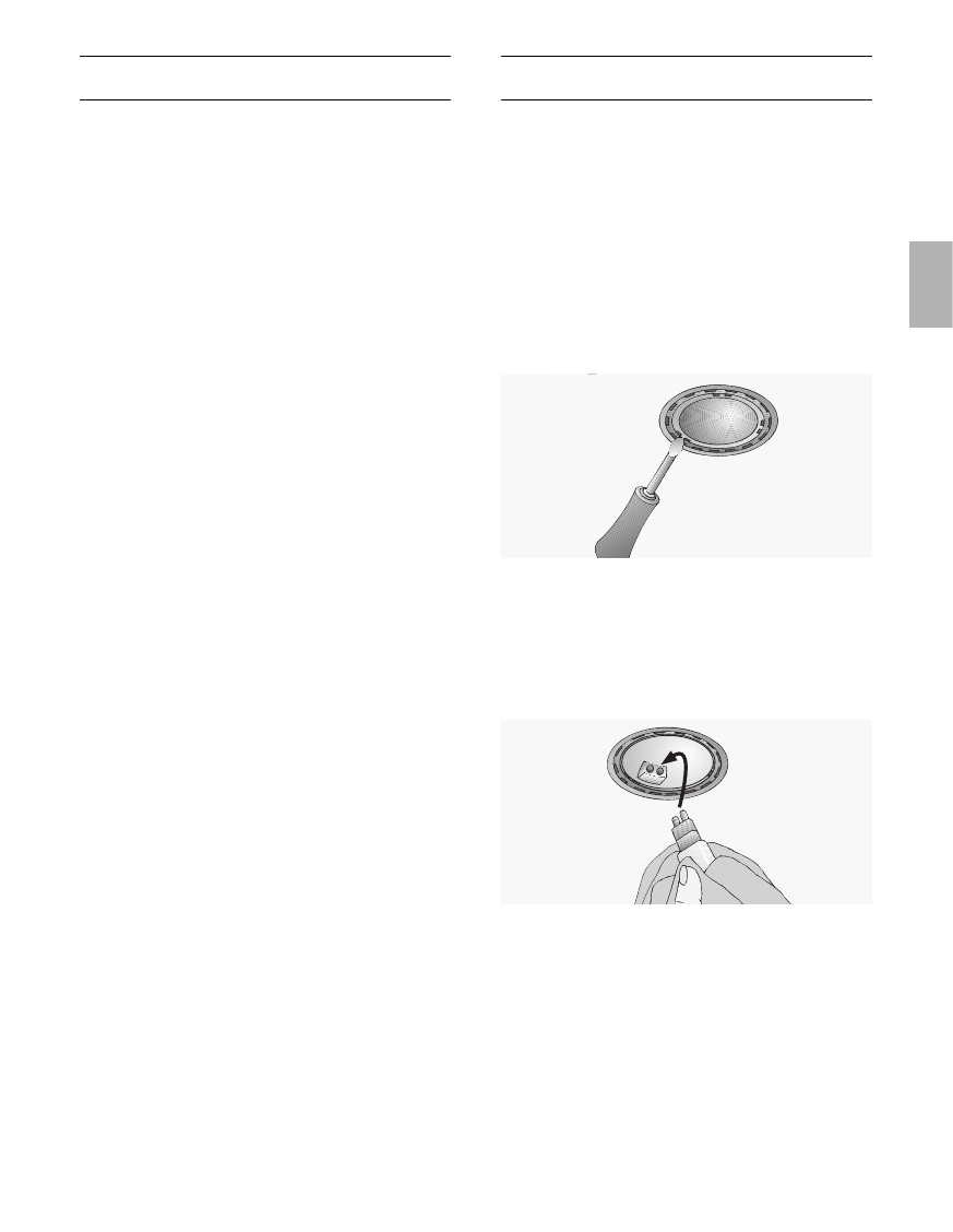
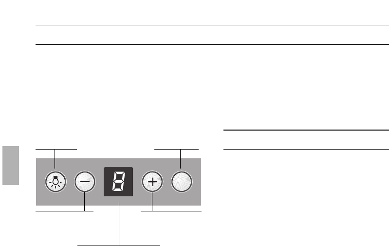
ṇ Light bulbs must always be fitted when
the extractor hood is in use.
ṇ Defective bulbs should be replaced
immediately to prevent the remaining bulbs
from overloading.
ṇ Never operate the extractor hood
without a grease filter.
ṇ Overheated fat or oil can easily catch fire.
If you are cooking with fat or oil, e.g. chips,
etc., never leave the cooker unattended.
ṇ Do not flambé food directly under the
extractor hood.
Risk of grease filter catching fire due
! to flames.
ṇ The hotplates must always be covered
with a utensil.
ṇ Restrictions apply to the use of the
extractor hood over a solid-fuel burner
(coal, wood, etc.). (See Installation
instructions).
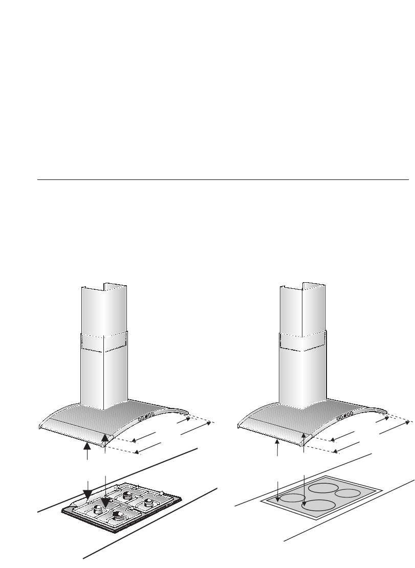
Gas hobs / Gas cookers
ṇ Do not use all the gas hotplates
simultaneously for a prolonged period
(max. 15 minutes) at maximum thermal
load, otherwise there is a risk of burns if the
housing surfaces are touched or a risk of
damage to the extractor hood. If the
extractor hood is situated over a gas hob,
operate the hood at maximum setting if
three or more gas hotplates are operated
simultaneously.
15