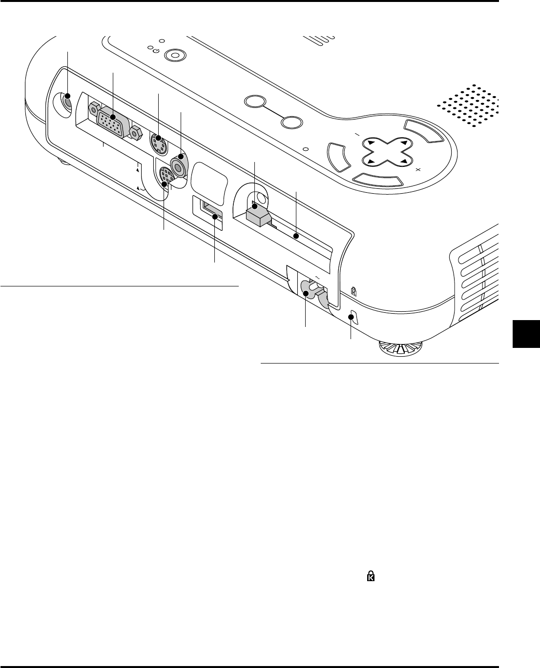
Connect your PC or other RGB equipment such as IBM or com-
patible computers. Use the supplied RGB cable to connect to a PC.
Or connect a Macintosh computer here using the supplied RGB
cable. This also serves as a component input connector that allows
you to connect a component video output of component equip-
ment such as a DVD player.
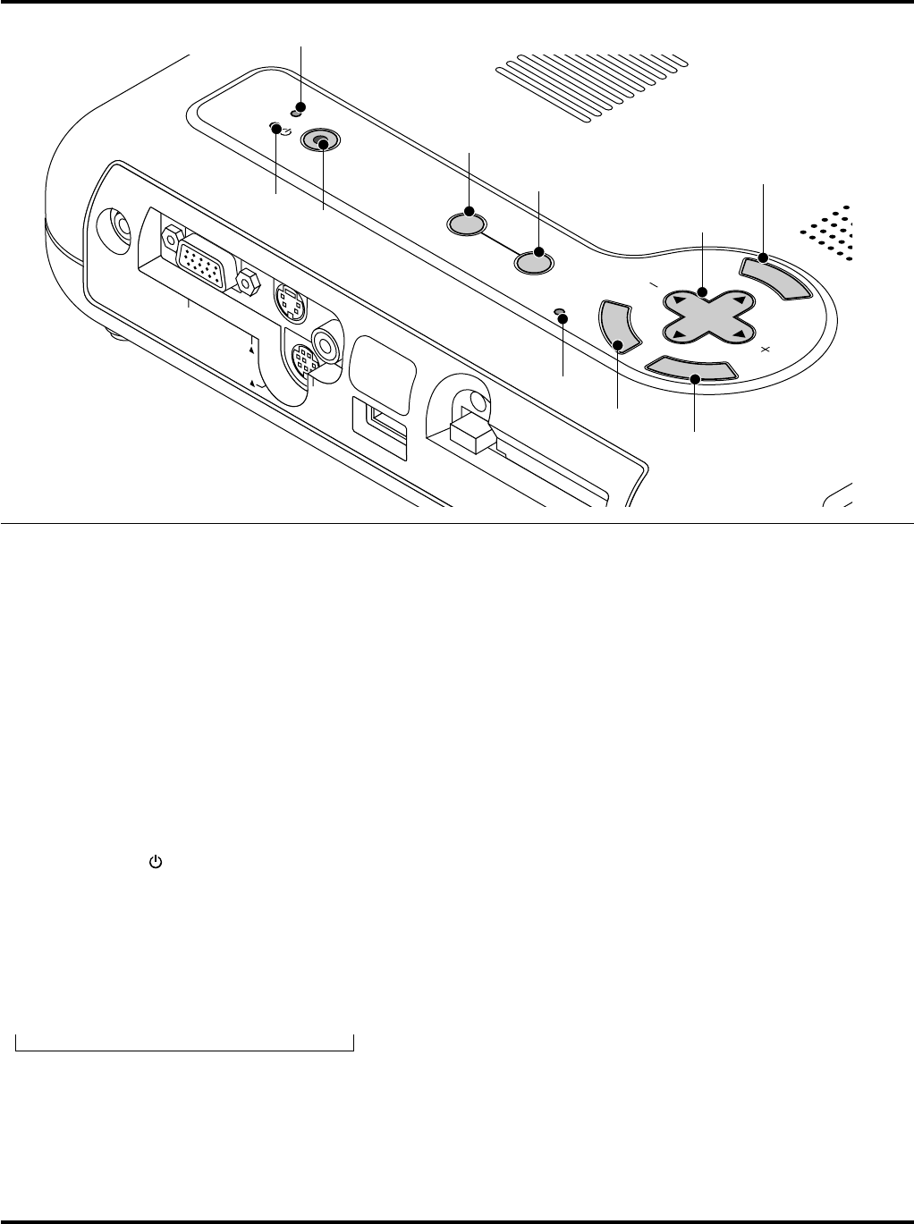
3. S-Video Input (Mini DIN 4 Pin)
Here is where you connect the S-Video input from an external source
like a VCR.
NOTE: S-Video provides more vivid color and higher resolution than the
traditional composite video format.
4. Video Input (RCA)
Connect a VCR, DVD player, laser disc player, or document cam-
era here to project video.
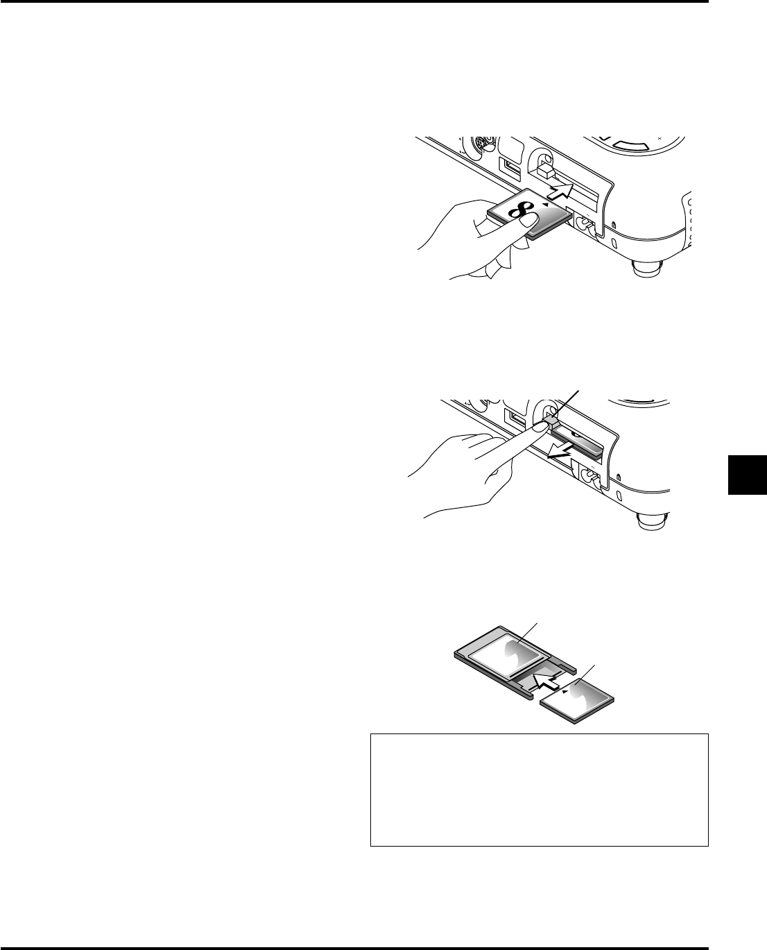
5. PC Card Eject Button
Press to eject a CompactFlash memory card.
6. PC Card Slot
Insert a CompactFlash memory card here.
7. PC Control Port (Mini DIN 8 Pin)
Use this port to connect your PC to control your projector via a
serial cable. This enables you to use your PC and serial communi-
cation protocol to control the projector. The NEC optional serial
cable is required to use this port. Also PC Control Utility 1.0 in-
cluded in the supplied CD-ROM must be installed on your PC.
If you are writing your own program, typical PC control codes are
on page E-59.
A cap is put on the port at the factory. Remove the cap when using
the port.
8. USB Terminal
Connect a commercially available mouse that supports USB. You
can operate the menu or PC Card Viewer with the USB mouse via
this terminal.
Note that this terminal is not used with a computer and that there
may be some brands of USB mouse that the projector does not
support.
9 AC Input
Connect the supplied power cable's three-pin plug here. When you
plug the other end into an active wall outlet, the POWER indicator
turns orange and the projector is in standby mode.
10 Built-in Security Slot ( )
This security slot supports the MicroSaver® Security System.
MicroSaver® is a registered trademark of Kensington Microware
Inc.
The logo is trademarked and owned by Kensington Microware Inc.
AC IN
P
C
C
A
R
D
U
S
B
M
E
N
U
E
N
T
E
R
C
A
N
C
E
L
SELECT
AUTO
ADJUST
PC CARD ACCESS
US
PO
WER
ON/
STAND BY
SOURCE
V
ID
E
O
S
-V
ID
E
O
R
G
B
A
U
D
IO
P
C
C
O
N
T
R
O
L
2
3
4
5
7
8
9
10
6
1
E–12
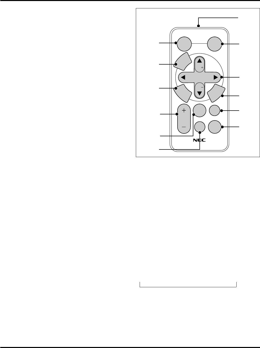
Remote Control Features
1. Infrared Transmitter
Direct the remote control toward the remote sensor on the projec-
tor cabinet.
2. Auto Adjust Button (RGB only)
Press this to automatically adjust the vertical/horizontal position,
clock frequency/phase and resolution if the projected picture is not
centered, if there are vertical stripes on the picture or if the picture
is flickering.
3. Select (▲▼
ᮤ ᮣ) / Volume (+) (–) Buttons
▲▼:Use these buttons to select the menu of the item you wish
to adjust.
When no menus appear, these buttons work as a volume
control.
ᮤ ᮣ:Use these buttons to change the level of a selected menu
item.
A press of the ᮣ button executes the selection.
When the menus or the Viewer tool bar is not displayed,
these buttons can be used to select a slide, or to move the
cursor in Folder List or Slide List.
When the pointer is displayed, these ▲▼ᮤ ᮣ buttons move
the pointer.
4. Cancel Button
Press this button to exit "Menus". Press this button to return to the
previous menu without storing the current settings or adjustments
when you are in the submenu or adjustment screen.
5. Picture Mute Button
This button turns off an image and sound for a short period of time.
Press again to restore the image and sound.
NOTE: When the menu is displayed, a press of this button mutes an image
and sound without turning off the menu.
6. Power Button
If the power is applied and the projector is in standby mode, you
can use this button to turn your projector on and off.
NOTE: To turn off the projector, press and hold the POWER button for a
minimum of two seconds.
7. Help Button
Provides information about operation and adjustment procedures
or the set information for the current menu or adjustment during
menu operation.
8. Pointer Button
Press this button to display one of the eight pointers; press again to
hide the pointer. You can move your pointer icon to the area you
want on the screen using the Select button.
9. Magnify Button (+) (–)
Use the (+) or (–) button to adjust the image size up to 400%.
When the pointer is displayed, the image is magnified about the
pointer as its center. When the pointer is not displayed, the image
is magnified about the screen center as its center.
When the image is magnified, the pointer is changed to the magni-
fying icon.
10. Enter Button
Press this button to execute the selected item. When this is pressed,
the adjustments and settings are saved, and the display is returned
to the menu.
11. Menu Button
Displays the menu for various settings and adjustments.
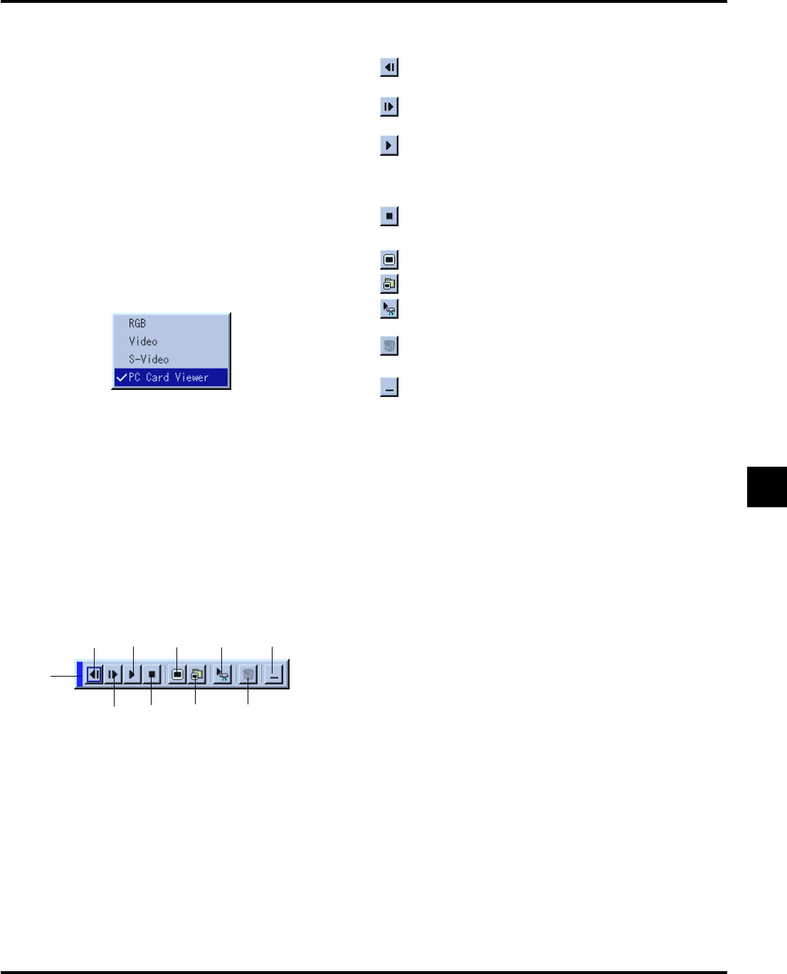
12. Source Button
Press this button to select a video source such as a PC, VCR, DVD
player or PC Card Viewer (CompactFlash card).
Each time this button is pressed, the input source will change as
follows:
→ RGB → Video → S-Video → PC Card Viewer
If no input signal is present, the input will be skipped.
Supplied Remote Control
SELECT
Vol.
Vol.
POINTER
POWER
HELP
RD-366E
PIC.
MUTE
MAGNIFY
SOURCE
AUTO
ADJ.
M
E
N
U
E
N
T
E
R
C
A
N
C
E
L
1
2
3
4
5
7
8
9
10
11
12
6
E–13
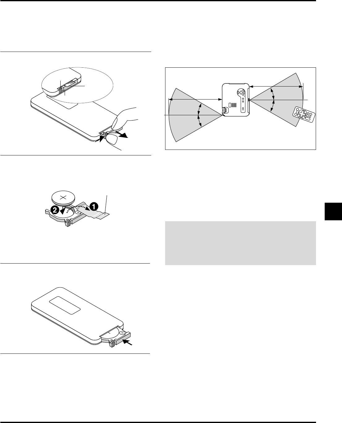
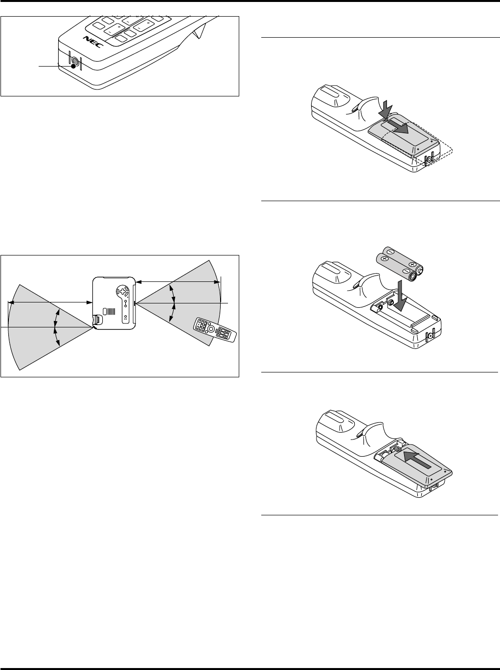
Operating Range
Remote Control Battery Installation
NOTE: Remove the transparent insulation tape by pulling it before use.
M
n
O
2
-
L
i
C
E
L
L
3
V
O
L
T
S
J
A
P
A
N
H
C
R
2
0
2
5
1
Push the catch to the right and remove the battery holder.
2
For the first use:
1.Remove the transparent insulation tape.
2.Place the Lithium coin cell on the battery holder. Ensure
that the side with the mark “+” is up.
M
n
O
2
-
L
i
C
E
L
L
3
V
O
L
T
S
J
A
P
A
N
H
CR2025
Transparent in-
sulation tape
Battery holder
Catch
Transparent insulation tape
For battery change
Remove the old Lithium coin cell and install new one
(CR2025).
Ensure that the side with the mark “+” is up.
3
Push the battery holder back into the remote control until
you feel a click.
M
n
O
2
-
L
i
C
E
L
L
3
V
O
L
T
S
J
A
P
A
N
H
C
R
2025
The infrared signal operates by line-of-sight up to a distance of ap-
proximately 22 feet (7m) and within a 60-degree angle of the remote
sensor. The projector will not function if there are objects between
the remote control and the remote sensor on the projector or if strong
light falls on the remote sensor. A weak battery will also prevent the
projector from operating
This sample may be slightly different from actual range
Remote Control Precautions
•Handle the remote control carefully.
•If the remote control gets wet, wipe it dry immediately.
•Avoid excessive heat and humidity.
•Do not place the battery upside down.
•Keep the coin cell battery out of reach of children so as not to
allow them to swallow the cell battery.
CAUTION:
Danger of explosion if battery is incorrectly replaced.
Replace only with the same or equivalent type recommended
by the manufacturer.
Dispose of used batteries according to your local regula-
tions.
30˚
7m
7m
30˚
30˚
30˚
E–14
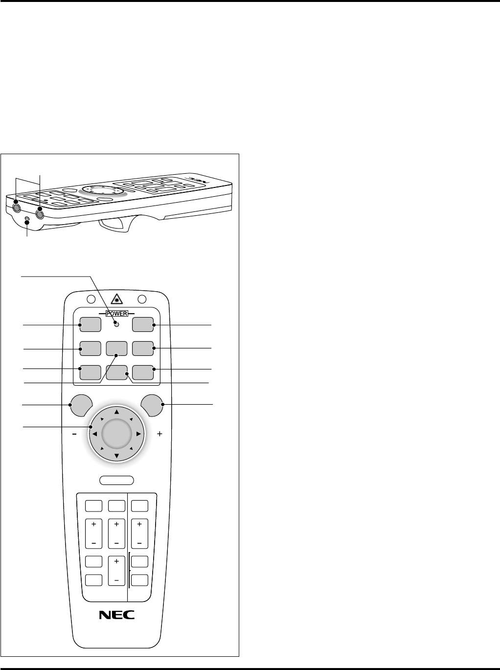
1. Infrared Transmitter
Direct the remote control toward the remote sensor on the projec-
tor cabinet.
2. Laser Pointer
Beams a laser light when "Laser" button is pressed.
3. LED
Flashes when any button is pressed.
4. Power On Button
If the main power is applied, you can use this button to turn your
projector on.
5. Power Off Button
If the main power is applied, you can use this button to turn your
projector off.
NOTE: To turn off the projector, press and hold the POWER OFF button for
a minimum of two seconds.
6. Video Button
Press this button to select an NTSC, PAL, SECAM or NTSC4.43
compatible video source from a VCR, DVD player, laser disc player
or document camera.
7. S-Video Button
Press this button to select an S-Video source from a VCR.
8. RGB 1 Button
Press this button to select a video source from computer or compo-
nent equipment connected to your RGB port.
9. RGB 2 Button
Not available on this model.
10. Auto Adjust Button (RGB only)
Press this button to automatically adjust the vertical/horizontal po-
sition, clock frequency/phase and resolution if the projected pic-
ture is not centered, if there are vertical stripes on the picture or if
the picture is flickering.
11. PJ Button
Press this button to switch the Mouse, Cancel/Right Click, and
Enter/Left Click buttons between the Projector mode (lit red) and
the Computer mode. Press this button or any one of the Menu,
Help, Pointer, PC Card, Folder List or Slide List buttons to switch
to the Projector mode and the PJ button lights red. To switch back
to the Computer mode, press the PJ button again.
12. Laser Button
Press and hold this button to activate the laser pointer. When lit,
you can use the laser to draw your audience's attention to a red dot
that you can place on any object.
13. Menu Button
Displays the menu for various settings and adjustments.
14. Mouse (▲▼ᮤ ᮣ) / (+) (–) Button
When you are in the Computer mode, these buttons work as a com-
puter mouse.
1
2
KEYSTONE
FREEZE
PIC
-
MUTE
HELP
POINTER
PC CARD
VIDEOS
-
VIDEO
AUTO ADJ.
RGB 1
MENULASER
R-CLICK /CANCEL
RGB 2P
J
ONOFF
MAGNIFY
VOL.
SLIDE
FOLDER
SLIDE
LIST
3
54
10
11
*
12
9
6
8
7
13*
14
Optional Presentation Remote Control (PR50KIT)
The PR50KIT enables your NEC projector and presentation control
with the same remote.
NOTE: If you are using a Macintosh computer, you can click either the right-
click or left-click button to activate the mouse.
NOTE: If any one of the buttons is pressed and held for 60 seconds or more,
the button operations will cease to operate. This is not a malfunction, rather it
is a feature used to prolong battery power.
To cancel this feature, press any one of the buttons other than the Mouse
button.
E–15
KEYSTONE
FREEZE
PIC
-
MUTE
HELP
POINTER
PC CARD
VIDEOS
-
VIDEO
AUTO ADJ.
RGB 1
MENULASER
R-CLICK /CANCEL
RGB 2P
J
ONOFF
MAGNIFY
VOL.
SLIDE
FOLDER
SLIDE
LIST
17*
18*
19
20
21
22
23
16
24*
25
26*
27*
15
When you are in the Projector mode, which is indicated by light-
ing the PJ button:
▲▼: Use these buttons to select the menu of the item you wish to
adjust.
ᮤ ᮣ: Use these buttons to change the level of a selected menu
item.
A press of the ᮣ button executes the selection.
When the pointer is displayed, these ▲▼ᮤ ᮣ buttons move the
pointer.
15. Enter / Left Click Button
When you are in the Computer mode, this button works as the
mouse left button.
When you are in the Projector mode, which is indicated by light-
ing the PJ button:
Use this button to enter your menu selection. It works the same
way as the "Enter" button on the cabinet or the card remote.
16. Cancel/ Right Click Button
When you are in the Computer mode, this button works as the
mouse right button.
When you are in the Projector mode, which is indicated by light-
ing the PJ button:
Press this button to exit "Menus". It works the same way as the
“Cancel” button on the cabinet or the card remote control.
17. Pointer Button
Press this button to display one of the eight pointers; press again to
hide the pointer. You can move your pointer icon to the area you
want on the screen using the Mouse button.
18. Help Button
Provides information about operation and adjustment procedures
or the set information for the current menu or adjustment during
menu operation.
19. Keystone (+) (–) Button
Press the (+) or (–) button to correct the keystone (trapezoidal)
distortion, and make the image square.
20. Magnify (+) (–) Button
Use this button to adjust the image size up to 400%.
When the pointer is displayed, the image is magnified about the
center of the pointer. When the pointer is not displayed, the image
is magnified about the center of the screen.
When the image is magnified, the pointer is changed to the magni-
fying icon.
21. Freeze Button
This button will freeze a picture. Press again to resume motion.
22. Picture Mute Button
This button turns off the image and sound for a short period of
time. Press again to restore the image and sound.
NOTE: When the menu is displayed, a press of this button mutes an image
and sound without turning off the menu.
23. Volume (+) (-) Button
Press (+) to increase the volume and (-) to decrease it.
24. PC Card Button
Press this button to select the PC Card Viewer source.
25. Slide (+) (-) Button
Press (+) to select the next folder or slide and (-) to select the pre-
vious folder or slide.
26. Folder List Button
Press this button to select PC Card Viewer source to display a list
of folders included in the CompactFlash memory card.
27. Slide List Button
Press this button to select PC Card Viewer source to display a list
of slides included in the CompactFlash memory card.
E–16
28. Remote Jack
Not available on this model.
*NOTE: The default is the Computer mode, which allows you to use the Mouse,
R-Click/Cancel, and L-Click/Enter buttons as your computer mouse. When
the MENU, HELP, POINTER, PC CARD, FOLDER LIST, or SLIDE LIST button is
pressed, the PJ button lights red to indicate that you are in the Projector mode.
If no buttons are pressed within 10 seconds, the light goes out and the Projec-
tor mode is canceled.
Operating Range for Optional Presentation Remote Control
When operating the projector:
FR
EEZE
P
IC
-
M
U
TE
CAR
D
FY
VOL.
S
L
ID
E
FOLDER
S
L
ID
E
L
IS
T
28
30˚
7m
7m
30˚
30˚
30˚
Remote Control Battery Installation
1
Press firmly and slide the battery cover off.
2
Remove both old batteries and install new ones (AA). Ensure
that you have the batteries' polarity (+/-) aligned correctly.
3
Slip the cover back over the batteries until it snaps into place.
Do not mix different types of batteries or new and old batteries.
Remote Control Precautions
•Handle the remote control carefully.
•If the remote control gets wet, wipe it dry immediately.
•Avoid excessive heat and humidity.
•If you will not be using the remote control for a long time, remove
the batteries.
•Do not place the batteries upside down.
•Do not look into the laser pointer while it is on.
•Do not point the laser beam at a person.
E–17
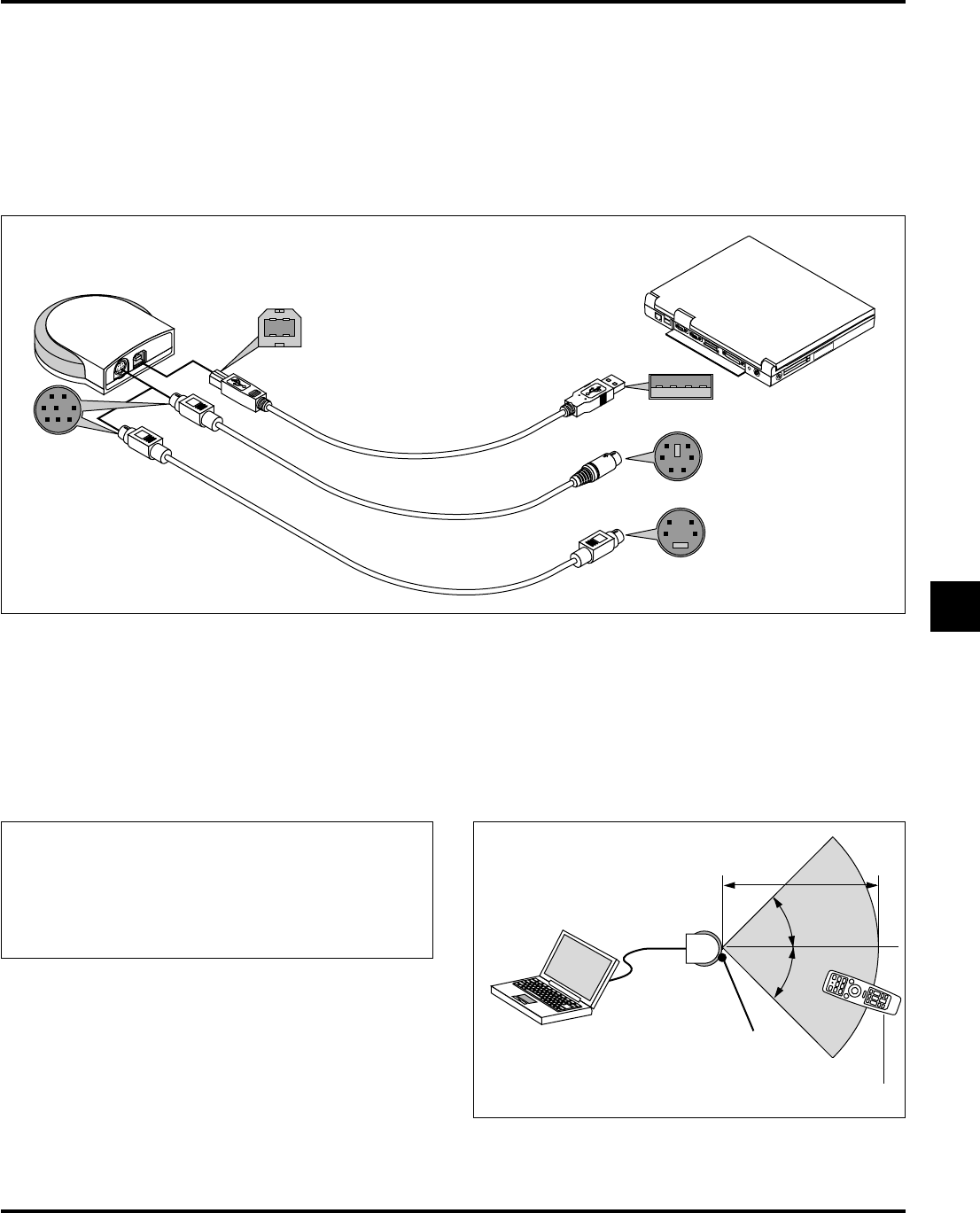
Using Remote Mouse Receiver (not supplied with the LT150/LT85 projector)
The remote mouse receiver enables you to operate your computer's mouse functions from the presentation remote control (Computer mode). It
is a great convenience for clicking through your computer-generated presentations. To return to the Projector mode, press the PJ button (lit red).
Connecting the remote mouse receiver to your computer
To use the remote mouse function, connect the remote mouse receiver to your computer with one of the remote mouse cables (USB, PS/2 or Mac
ADB) included with the optional presentation remote control kit PR50KIT. Choose the appropriate mouse cable for your computer.
NOTE: Depending on the type of connection or OS installed on your computer, you may have to restart your computer or change your computer settings.
Computer
To USB port of PC or
Macintosh
To Mouse port of PC
To ADB port of Macintosh
USB Cable
PS/2 Cable
Mac (ADB) Cable
To USB
To PS/2 or Mac
Notes on Connecting with USB Cable
*When you use an IBM PC, the PR50KIT does not support the other operating systems than Windows 98/2000.
*Do not pull out the cable from the USB port of your PC or the remote mouse receiver and then immediately insert it back into the USB port.
Allow a minimum of 5 seconds to elapse between insertion and extraction of the cable.
Doing so repeatedly can result in your PC failing to detect the remote mouse receiver.
*The supplied USB cable is designed especially for the PR50KIT. If you use the USB cable with other equipment, we do not assure the correct
functioning of the equipment.
7m
30˚
30˚
Remote sensor on the remote
mouse receiver
Presentation remote control
Remote mouse receiver
Package List of PR50KIT:
* Remote control RD-367E
* Two batteries (AA)
* Remote mouse receiver
* Three remote mouse cables (for USB, PS/2 and Mac ADB)
* Remote control case
* User's manual
When operating a computer via the optional remote mouse receiver
E–18
KEYSTONE
FREEZE
PIC
-
MUTE
HELP
POINTER
PC CARD
VIDEOS
-
VIDEO
AUTO ADJ.
RGB 1
MENULASER
R-CLICK /CANCEL
L-CLICK/ENTER
RGB 2P
J
ONOFF
MAGNIFY
VOL.
SLIDE
FOLDER
SLIDE
LIST
KEYSTONE
FREEZE
PIC
-
MUTE
HELP
POINTER
PC CARD
VIDEOS
-
VIDEO
AUTO ADJ.
RGB 1
MENULASER
R-CLICK /CANCEL
L-CLICK/ENTER
RGB 2P
J
ONOFF
MAGNIFY
VOL.
SLIDE
FOLDER
SLIDE
LIST
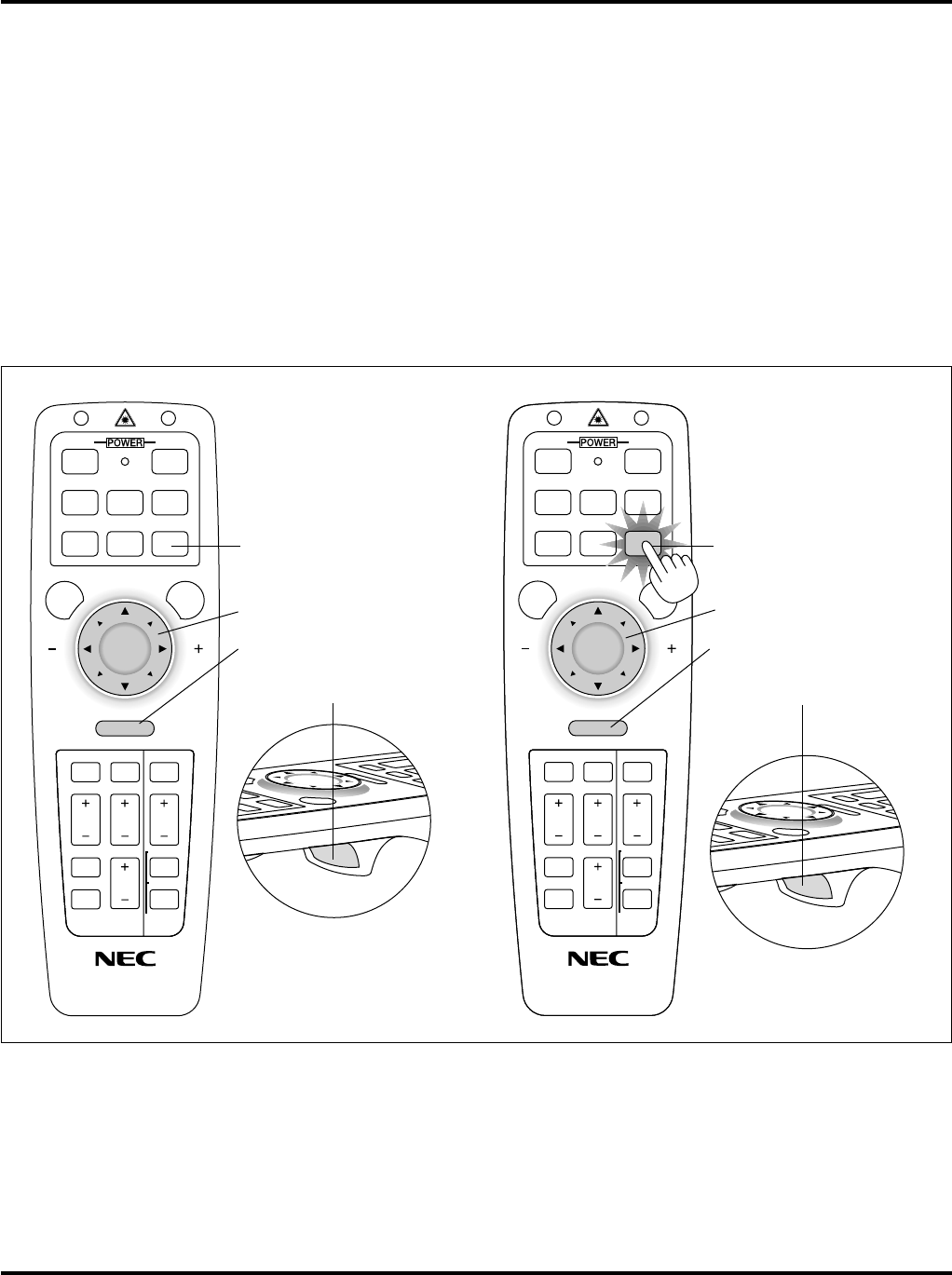
Switching operation mode between mouse and projector
The three shaded buttons shown on the drawing work as a computer mouse in the Computer mode.
In the Computer mode the PJ button is not lit.
*When the MENU button is pressed, the PJ button lights red to indicate that you are in the Projector mode, which allows the projector menu
operation using the three buttons.
*When the POINTER button is pressed, the PJ button lights red to indicate that you are in the Projector mode and that the MOUSE▲▼ᮤ ᮣ
button works as a moving button for the POINTER or magnified image.
*If no buttons are pressed within 10 seconds, the PJ button's light goes out to indicate that you are in the Computer mode. To enable the
projector menu operation again, press the PJ button to light red. To move the pointer or a magnified image again, turn off the pointer and then
turn on the pointer (press the POINTER button two times).
*When the PJ button is lit, if you want to use the mouse function immediately, press the PJ button to return to the Computer mode (not lit).
Not lit
Works as a mouse for your computer.
Works as a right-click button for your computer.
Works as a left-click button for your computer.
Works as the Select button on the projector.
Works as the Cancel button on the projector.
Works as the Enter button on the projector.
Lit red
E–19
2. INSTALLATION
This section describes how to set up your MultiSync LT150/LT85 projector and how to connect video and audio sources.
Setting up Your Projector
Your MultiSync LT150/LT85 Projector is simple to set up and use. But before you get started, you must first:
1. Determine the image size.
2. Set up a screen or select a non-glossy white wall onto which you can project your image.
Ensure that the power cable and any other cables connecting to video sources are disconnected before moving the projector.
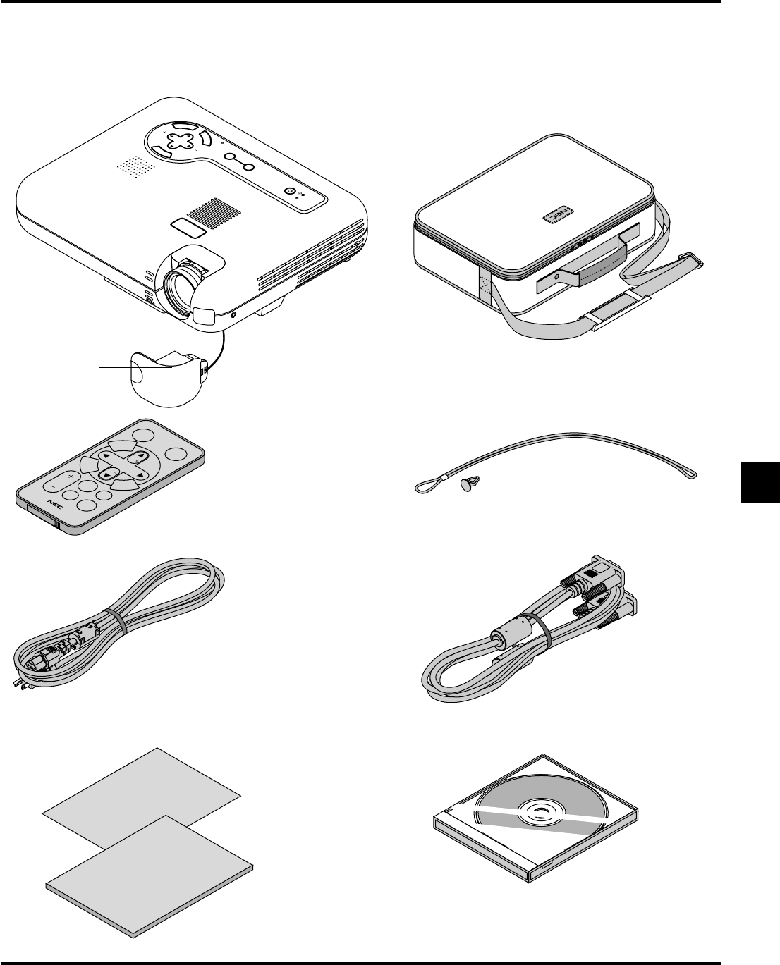
When moving the projector or when it is not in use, cover the lens with the lens cap.
Selecting a Location
The further your projector is from the screen or wall, the larger the image. The minimum size the image can be is approximately 36" (0.9 m)
measured diagonally when the projector is roughly 4 feet (1.2 m) from the wall or screen. The largest the image can be is 200" (5.1 m) when the
projector is about 22 feet (6.6 m) from the wall or screen.
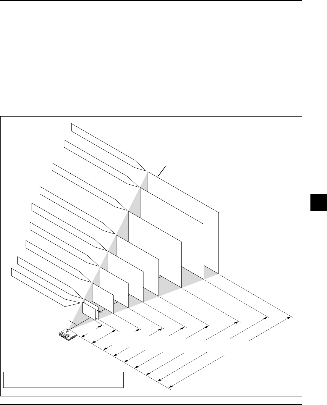
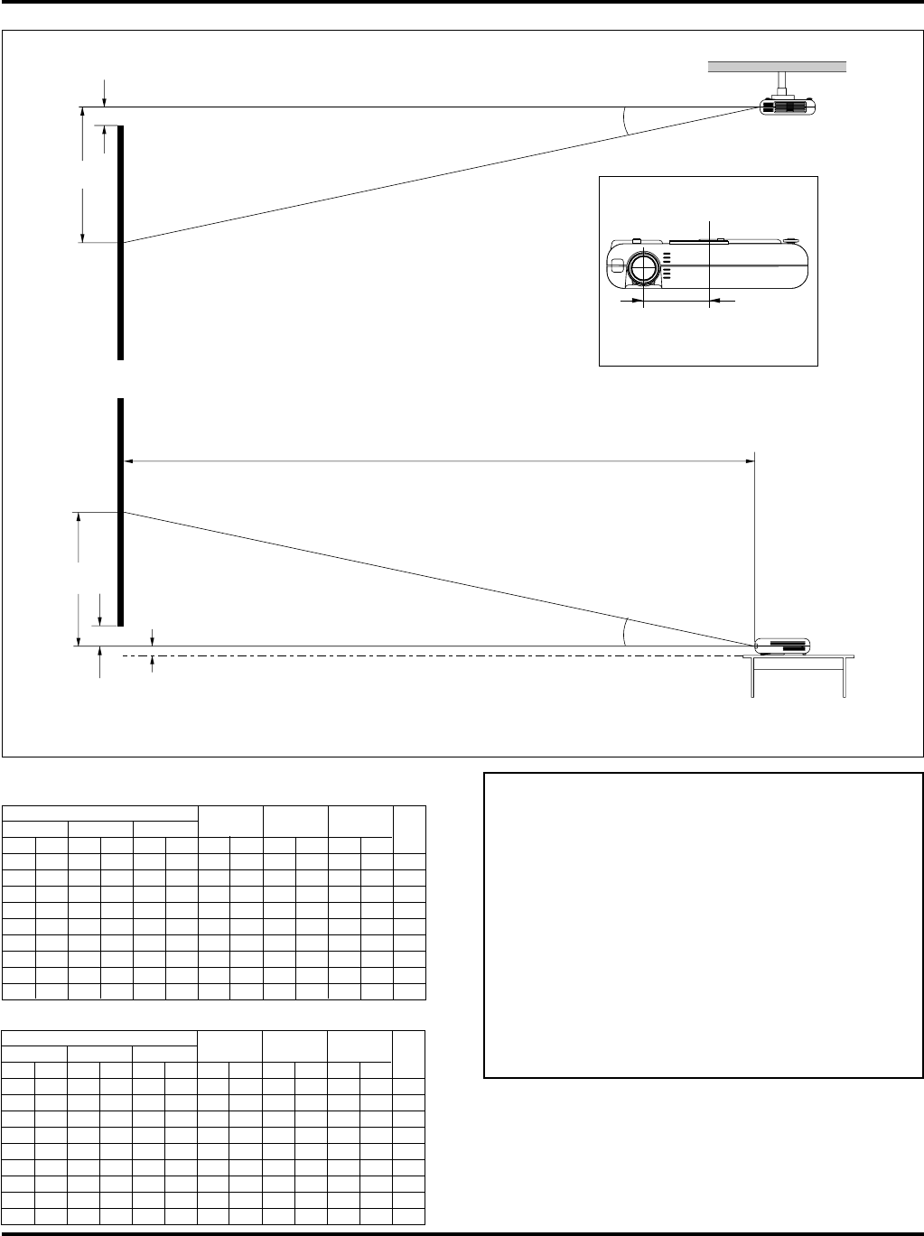
Screen and Projection Distance
The following shows the proper relative positions of the projector and screen. Refer to the table to determine the position of installation.
406.4(W) X 304.8(H) / 160(W) X 120(H)
365.8(W) X 274.3(H) / 144(W) X 108(H)
304.8(W) X 228.6(H) / 120(W) X 90(H)
243.8(W) X 182.9(H) / 96(W) X 72(H)
203.2(W) X 152.4(H) / 80(W) X 60(H)
162.6(W) X 121.9(H) / 64(W) X 48(H)
121.9(W) X 91.4(H) / 48(W) X 36(H)
81.3(W) X 61.0(H) / 32(W) X 24(H)
73.2(W
) X
54.9(H
) / 28.8(W
) X
21.6(H
)
Screen size (Unit: cm / inch)
Lens center
1.3 / 4.4
(1.4 / 4.6)
2.0 / 6.6 (2.1 / 6.8)
2.7 / 8.7 (2.8 / 9.1)
3.3 / 10.9 (3.5 / 11.3)
4.0 / 13.1 (4.1 / 13.6)
5.0 / 16.3 (5.2 / 17.0)
6.0 / 19.6 (6.2 / 20.3)
6.6 / 21.8 (6.9 / 22.6)
1.2 / 3.9
200"
Screen
180"
150"
120"
100"
80"
60"
40"
36"
Throwing distance
Unit: m / feet
The figures given in parentheses are throwing distances
for LT85.
E–20
WARNING
*Do not attempt to install the projector yourself.
•Only use your projector on a solid, level surface. If the projec-
tor falls to the ground, you can be injured and the projector
severely damaged.
•Do not use the projector where temperatures vary greatly. The
projector must be used at temperatures between 32˚F (0˚C)
and 95˚F (35˚C).
•Do not expose the projector to moisture, dust, or smoke. This
will harm the screen image.
•Ensure that you have adequate ventilation around your pro-
jector so heat can dissipate. Do not cover the vents on the side
or the front of the projector.
Reflecting the Image
Using a mirror to reflect your projector’s image enables you to enjoy
a much larger image. Contact your NEC dealer if you need a mirror.
If you’re using a mirror and your image is inverted, use the “Menu”
and “Select” buttons on your projector cabinet or ▲▼ buttons on
your remote control to correct the orientation. (See page E-40.)
Distance Chart
Screen Size
DiagonalWidthHeightBCDα
inchmminchmminchmminchmminchmminchmm
3691428.873221.654914.536847.212003.79417.1
401016328132461016.141052.813404.110517.0
6015244812193691424.261478.720006.215717.1
80203264162648121932.2819104.726608.220917.1
100254080203260152440.31024130.7332010.326217.1
120304896243872182948.31228157.1399012.431417.1
1503810120304890228660.51536196.1498015.539317.1
18045721443658108274372.61843235.0597018.547117.2
20050801604064120304880.62048261.0663020.652417.2
Screen Size
DiagonalWidthHeightBCDα
inchmminchmminchmminchmminchmminchmm
3691428.873221.654914.937847.212004.110417.5
401016328132461016.742554.713904.712017.0
6015244812193691425.163781.920807.118017.0
80203264162648121933.5850108.727609.524017.1
100254080203260152441.81062135.8345011.830017.1
120304896243872182950.21274162.6413014.236017.1
1503810120304890228662.81594203.5517017.845117.1
18045721443658108274375.31913244.1620021.354117.1
20050801604064120304883.72125270.9688023.760117.2
LT150
LT85
B=Vertical distance between lens center and screen centerC=Throw distance
D=Vertical distance between lens center and top of screen (bottom of screen for desktop)α=Throw angle
Lens Center
B
D
Screen Top
Screen Center
Throw Distance
C
α
Lens Offset from Center of Projector
2.97” (75.5mm)
Screen Bottom
Screen Center
Projector feet
1.5”(38mm)
D
B
Lens Center
Throw Distance
C
α
NOTE: Distances may vary +/-5%.
Ceiling Installation
E–21
VIDEO
S-VIDEO
RGB
AUDIO
PC CONTROL
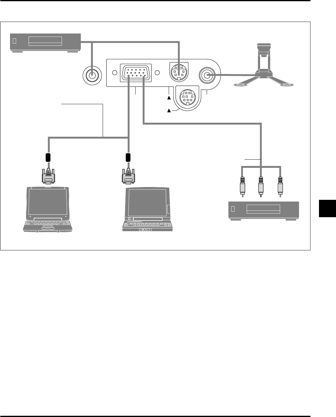
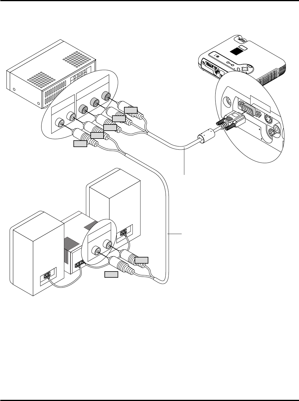
Wiring Diagram
Optional Component V cable
To video, S-video, and audio
inputs on the projector.
RGB Signal cable (supplied)
To mini D-Sub 15-pin connector on the
projector. It is recommended that you use a
commercially available distribution amplifier if
connecting a signal cable longer than the
supplied cable.
IBM VGA or Compatibles
(Desktop type or notebook type)
Macintosh
(Desktop type or notebook type)
Document Camera
DVD Player (with component output)
VCR, DVD Player or LaserDisc Player
NOTE: When using with a notebook PC, be sure to connect between the projector and the notebook PC before turning on the power to the notebook PC. In most
cases signal cannot be output from RGB output unless the notebook PC is turned on after connecting with the projector.
NOTE:
*If the screen goes blank while using your remote control, it may be the result of the computer’s screen-saver or power management software.
*If you accidentally hit the POWER button on the remote control, wait 90 seconds and then press the POWER button again to resume.
NOTE: If using video, S-video, or audio cables, the cables should be 3 m (9.8 feet) or shorter.
E–22
A
C
I
N
PC CAR
D
U
SB
VIDEO
S-VIDE
O
RGB
AUD
IO
PC CO
NT
ROL
M
E
N
U
E
N
T
E
R
C
A
N
C
E
L
S
E
L
E
C
T
A
U
T
O
A
D
J
U
S
T
P
C
C
A
R
D
A
C
C
E
S
S
S
T
A
T
U
S
P
O
W
E
R
O
N
/
S
T
A
N
D
B
Y
S
O
U
R
C
E
VIDEO
S-VIDEO
RGB
AUDIO
PC CONTROL
RGB INPUT
AUDIO
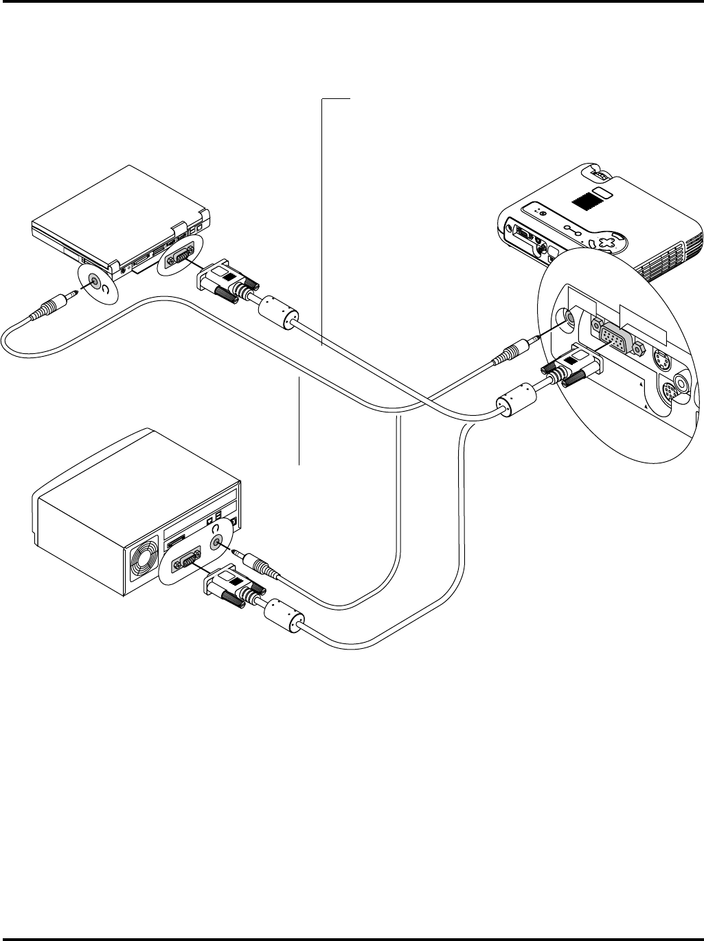
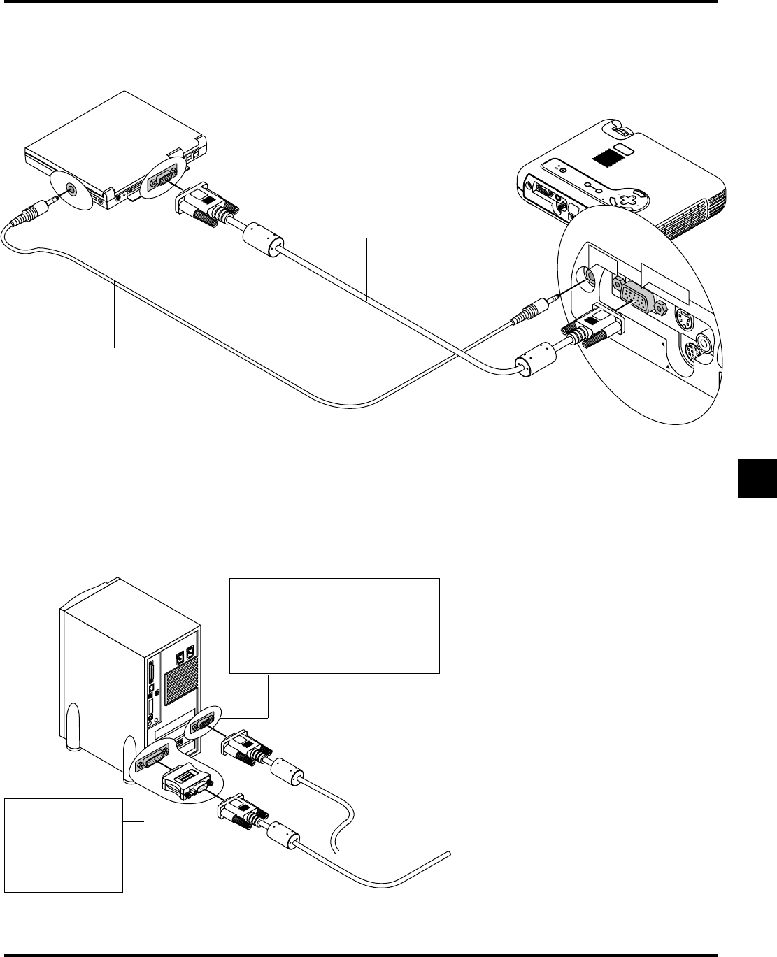
Connecting Your PC
IBM VGA or Compatibles
(Notebook type)
RGB signal cable (supplied)
To mini D-Sub 15-pin connector on the projector. It is recom-
mended that you use a commercially available distribution ampli-
fier if connecting a signal cable longer than the supplied one.
IBM VGA or Compatibles
(Desktop type)
Audio cable
(not supplied)
Connecting your PC to your MultiSync LT150 (XGA)/ LT85 (SVGA) projector will enable you to project your computer’s screen image for an
impressive presentation.
To connect to a PC, simply:
1.Turn off the power to your projector and computer.
2.Use the supplied signal cable to connect your PC to the projector.
3.Turn on the projector and the computer.
4.If the projector goes blank after a period of inactivity, it may be caused by a screen saver installed on the computer you’ve connected to the
projector.
E–23
A
C
IN
PC CARD
USB
VIDEO
S-VIDEO
RGB
AUDIO
PC CONTROL
M
E
N
U
E
N
T
E
R
C
A
N
C
E
L
SE
LEC
T
AUTO
AD
JUST
PC CARD ACCESS
S
TATUS
PO
WER
ON/
STAN
D BY
SO
UR
CE
VIDEO
S-VIDEO
RGB
AUDIO
PC CONTROL
RGB INPUT
AUDIO
1
O
N
D
I
P
2
34
56
To connect to a Macintosh, simply:
1.Turn off the power to your projector and your Macintosh com-
puter.
2.Use the supplied signal cable to connect your Macintosh com-
puter to the projector.
3.Turn on the projector and the Macintosh computer.
Connecting Your Macintosh Computer
Macintosh (Desktop type)
Audio cable
(not supplied)
For older Macintosh,
use a commercially
available pin
adapter to connect to
your Mac's video
port.
Pin adapter for Macintosh
(not supplied)
RGB Signal cable
(supplied)
NOTE: The new Macintosh computer
such as G3 will have the 15 pin HD con-
nector. The LT150/LT85's "Plug and
Play" data will be downloaded to the
Macintosh. Therefore, a Mac adapter
will not be necessary.
Macintosh (Notebook type)
E–24
AC
IN
PC CARD
USB
VIDEO
S-VIDEO
RGB
AUDIO
PC CONTROL
M
E
N
U
E
N
T
E
R
C
A
N
C
E
L
S
E
L
E
C
T
AUTO
ADJU
ST
PC CAR
D
ACCESS
STATUS
POWER
ON/
STAND BY
SOURCE
VIDEO
S-VIDEO
RGB
AUDIO
PC CONTROL
RGB INPUT
Y Cb Cr
R L
R L
You can connect your projector to a DVD player with component outputs or Video output. To do so, simply:
1.Turn off the power to your projector and DVD player.
2.If your DVD player has the component video (Y,Cb,Cr) output, use the optional 15-pin-to-RCAן3 cable to connect your DVD player to the
RGB INPUT connector on the projector.
For a DVD player without component video (Y,Cb,Cr) outputs, use common RCA cables (not provided) to connect a composite VIDEO
output of the DVD player to the Video Input of the projector.
3.Turn on the projector and DVD player.
NOTE: Refer to your DVD player’s owner’s manual for more information about your DVD player’s video output requirements,
Connecting Your DVD Player
Optional 15-pin-to-RCAן3 cable (optional)
(Component V )
Audio cable
(not supplied)
DVD player
White
Red
Y
Cb
Cr
White
Red
Audio Equipment
E–25
A
C
IN
PC CARD
USB
VIDEO
S-VIDEO
RGB
AUD
IO
PC CONT
ROL
M
E
N
U
E
N
T
E
R
C
A
N
C
E
L
S
E
L
E
C
T
A
UT
O
A
DJ
U
ST
PC C
AR
D
AC
C
ESS
STA
TU
S
P
OWE
R
O
N
/
ST
AN
D BY
SOU
R
CE
VIDEO
S-VIDEO
RGB
AUDIO
PC CONTROL
VIDEO
S-VIDEO
R L
R L
VIDEO
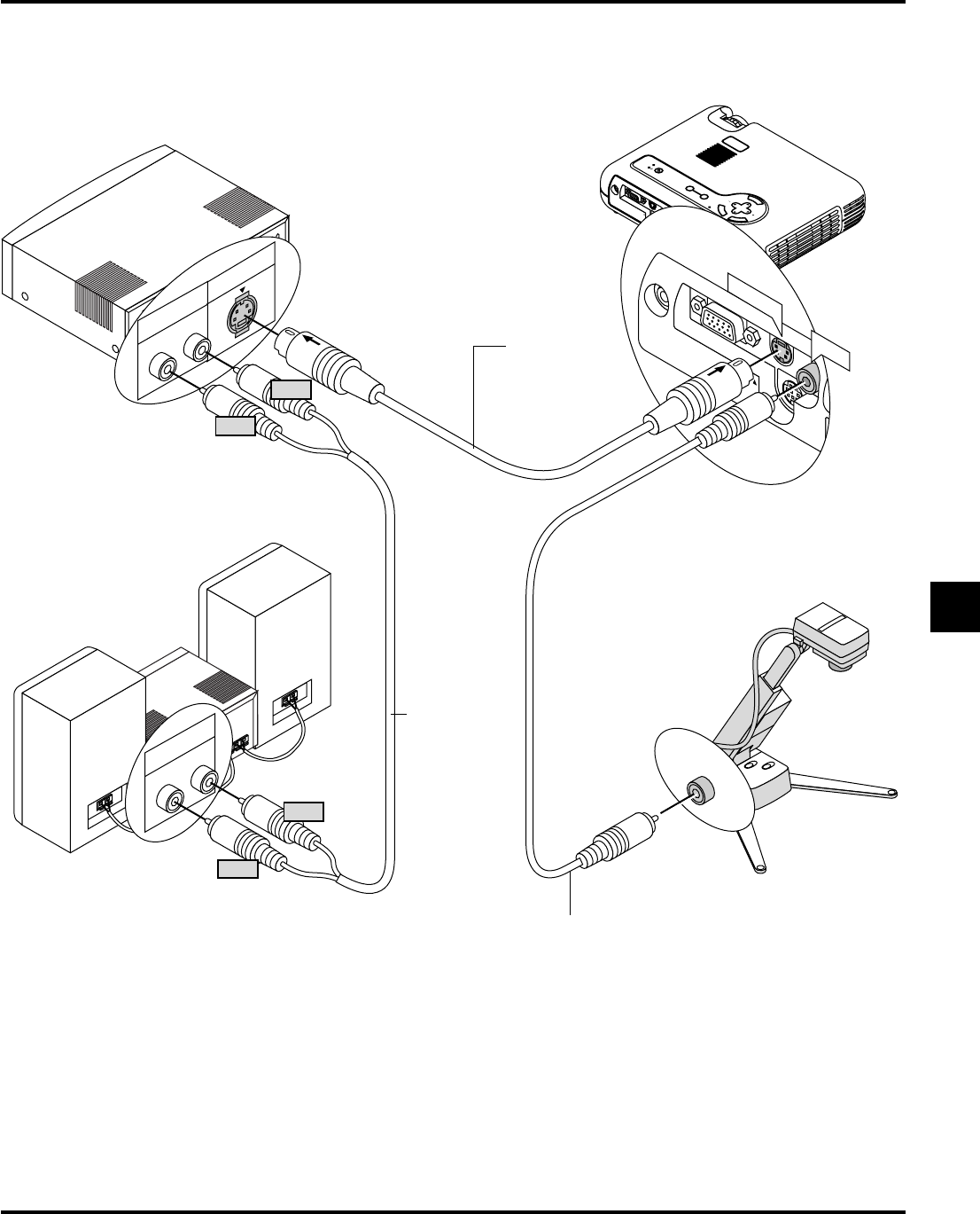
Use common RCA cables (not provided) to connect your VCR, laser disc player or document camera to your projector.
To make these connections, simply:
1.Turn off the power to the projector and VCR, laser disc player or document camera.
2.Connect one end of your RCA cable to the video output connector on the back of your VCR or laser disc player, connect the other end to the
Video input on your projector. Use an audio cable (not supplied) to connect the audio from your VCR or laser disc player to your audio
equipment (if your VCR or laser disc player has this capability). Be careful to keep your right and left channel connections correct for stereo
sound.
3.Turn on the projector and the VCR or laser disc player.
NOTE: Refer to your VCR or laser disc player owner’s manual for more information about your equipment’s video output requirements.
VCR/ Laser disc player
Connecting Your VCR or Laser Disc Player
S-video cable
(not supplied)
Audio cable
(not supplied)
Audio equipment
Document camera
Video cable (not supplied)
Red
White
Red
White
E–26
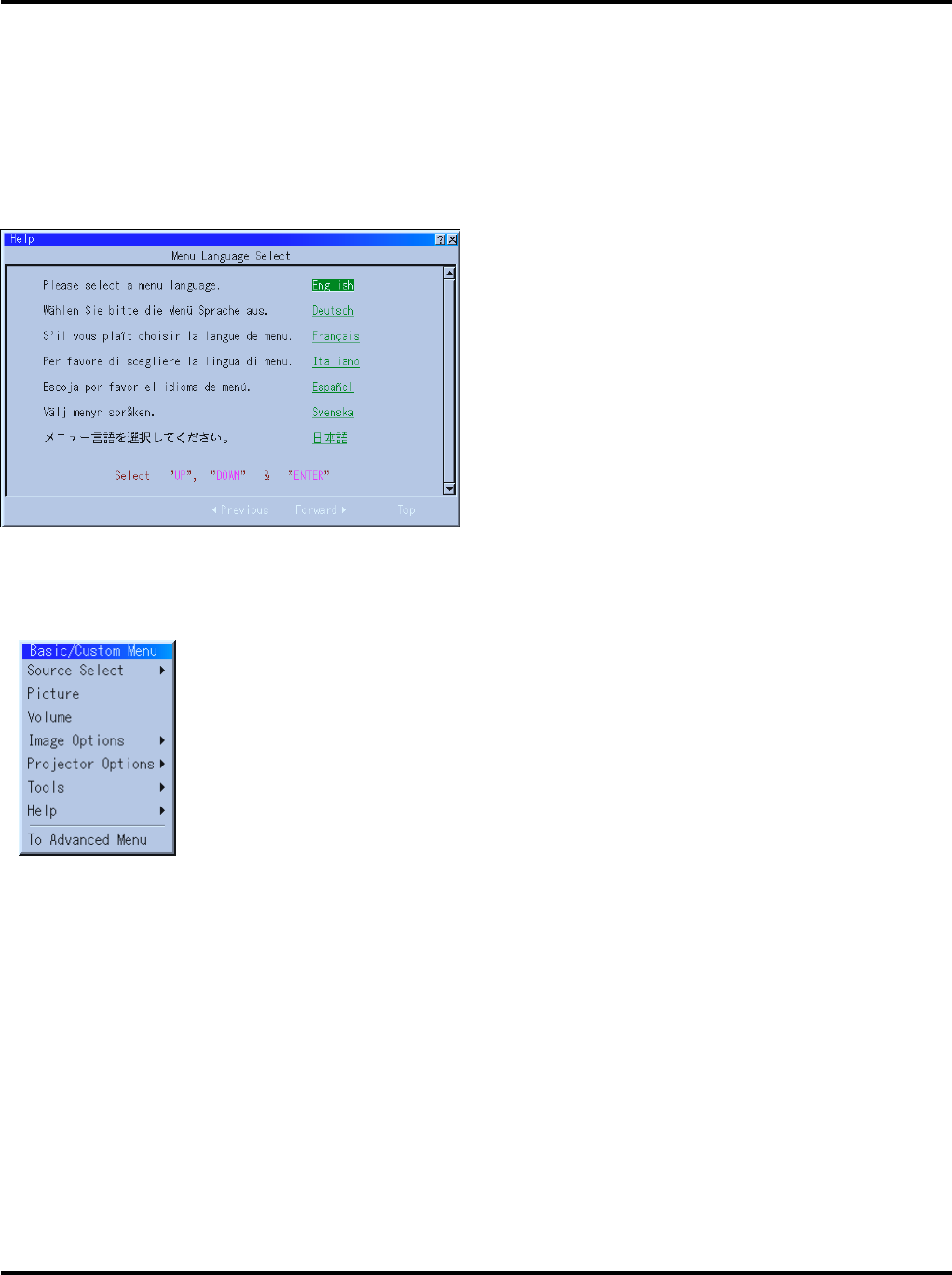
About Startup screen (Menu Language Select screen)
When you first turn on the projector, you will get the Startup screen.
This screen gives you the opportunity to select one of the seven menu
languages: English, German, French, Itilan, Spanish,Swedish and
Japanese.
To select a menu language, follow these steps:
1.Use the Select ▲ or ▼ button to select one of the seven languages
for the menu.
2.Press the Enter button to execute the selection.
3.The Basic/Custom menu will be displayed in the language you
have selected.
To close the menu, press the Cancel button.
After this has been done, you can proceed to the advanced menu
operation.
If you want, you can select the menu language later. See “Language”
on page E-40.
E–27
R
GB
STATUS
POWER
ON/
STAND BY
SOURCE
3.OPERATION
A
C
I
N
P
C
C
A
R
D
U
S
B
V
I
D
E
O
S
-
V
I
D
E
O
R
G
B
A
U
D
I
O
P
C
C
O
N
T
R
O
L
M
E
N
U
E
N
T
E
R
C
A
N
C
E
L
S
E
L
E
C
T
A
U
T
O
A
D
J
U
S
T
P
C
C
A
R
D
A
C
C
E
S
S
S
T
A
T
U
S
P
O
W
E
R
O
N
/
S
T
A
N
D
B
Y
S
O
U
R
C
E
1
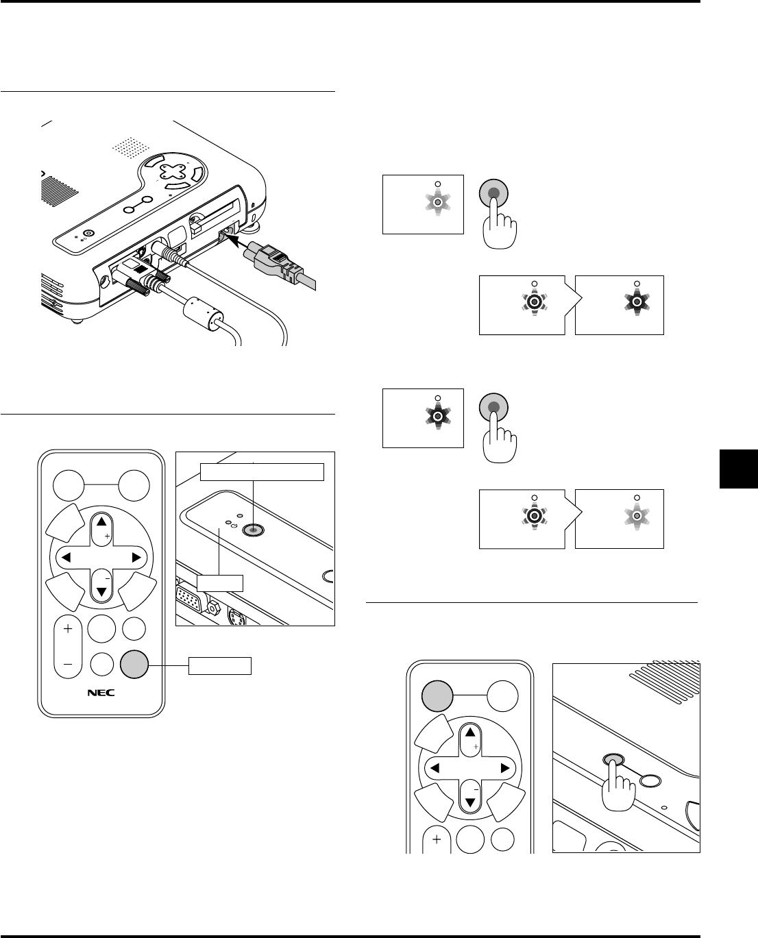
Connect the supplied power cable to the projector.
2
Turn on and off the Projector
3
Connecting the Power Cable and Turn on the Projector
POWER ON/STAND BY button
Indicator
To turn on the projector:
Only after you press the “POWER” button on the projector
cabinet or the remote control will the power indicator turn to
green and the projector become ready to use.
NOTE: To turn the projector on by plugging in the power cable, use
the menu and enable the “Auto Start” feature. (See page E-42.)
NOTE: Immediately after turning on the projector, screen flicker may
occur. This is not a fault. Wait 3 to 5 minutes until the lamp lighting
is stabilized.
Power button
To turn off the projector:
First press the “POWER” button on the projector cabinet or
the remote control for a minimum of two seconds. The power
indicator will glow orange. After the projector turns off, the
cooling fans keep operating for 90 seconds.
NOTE: Do not disconnect the power cable during this time. Then,
unplug the power cable. The power indicator will go out.
SELECT
Vol.
Vol.
POINTER
POWER
HELP
RD-366E
PIC.
MUTE
MAGNIFY
SOURCE
AUTO
ADJ.
M
E
N
U
E
N
T
E
R
C
A
N
C
E
L
POWER
STATUS
POWER
STATUS
ON
/
STAND BY
POWER
STATUS
POWER
STATUS
POWER
STATUS
ON
/
STAND BY
POWER
STATUS
Status of indicator light: turn on
stand by
flashing 3 to 5 minutes
steady light
Status of indicator light: turn off
steady orange light
flashing green lightsteady green light
ON
cooling down
stand by
steady green light
change to flashing
green light
steady orange light
press a minimum of
two seconds
SELECT
Vol.
Vol.
POINTER
PIC.
MUTE
SOURCE
AUTO
ADJ.
M
E
N
U
E
N
T
E
R
C
A
N
C
E
L
E
N
T
E
R
A
U
T
O
A
D
J
U
S
T
P
C
C
A
R
D
A
C
C
E
S
S
O
N
/
A
N
D
B
Y
S
O
U
R
C
E
Select the Computer or Video Source
Adjust a Projected Image
Plug the supplied power cable in the wall outlet. The projec-
tor will go into its standby mode and the power indicator will
glow orange.
Before you turn on your projector, ensure that the computer or video
source is turned on and that your lens cap is removed.
E–28
Press the Source button on the remote control or the projec-
tor cabinet to select “Video” (VCR, document camera, or la-
ser disc player), S-Video”, “RGB” (computer or DVD with
component output) or “PC Card Viewer” (slides on a
CompactFlash card) to display the image.
Or press the “Menu” button on the remote control or the cabi-
net and use the menu to select your video source: “Video”,
“S-Video”, “RGB” or “PC Card Viewer”.
NOTE: If no input signal is available, the projector will display a blue
background (factory preset).
Adjust the Image Size and the Focus
Move the projector back and forth to fine adjust the image
size on the screen
Use the Focus ring to obtain the best focus.
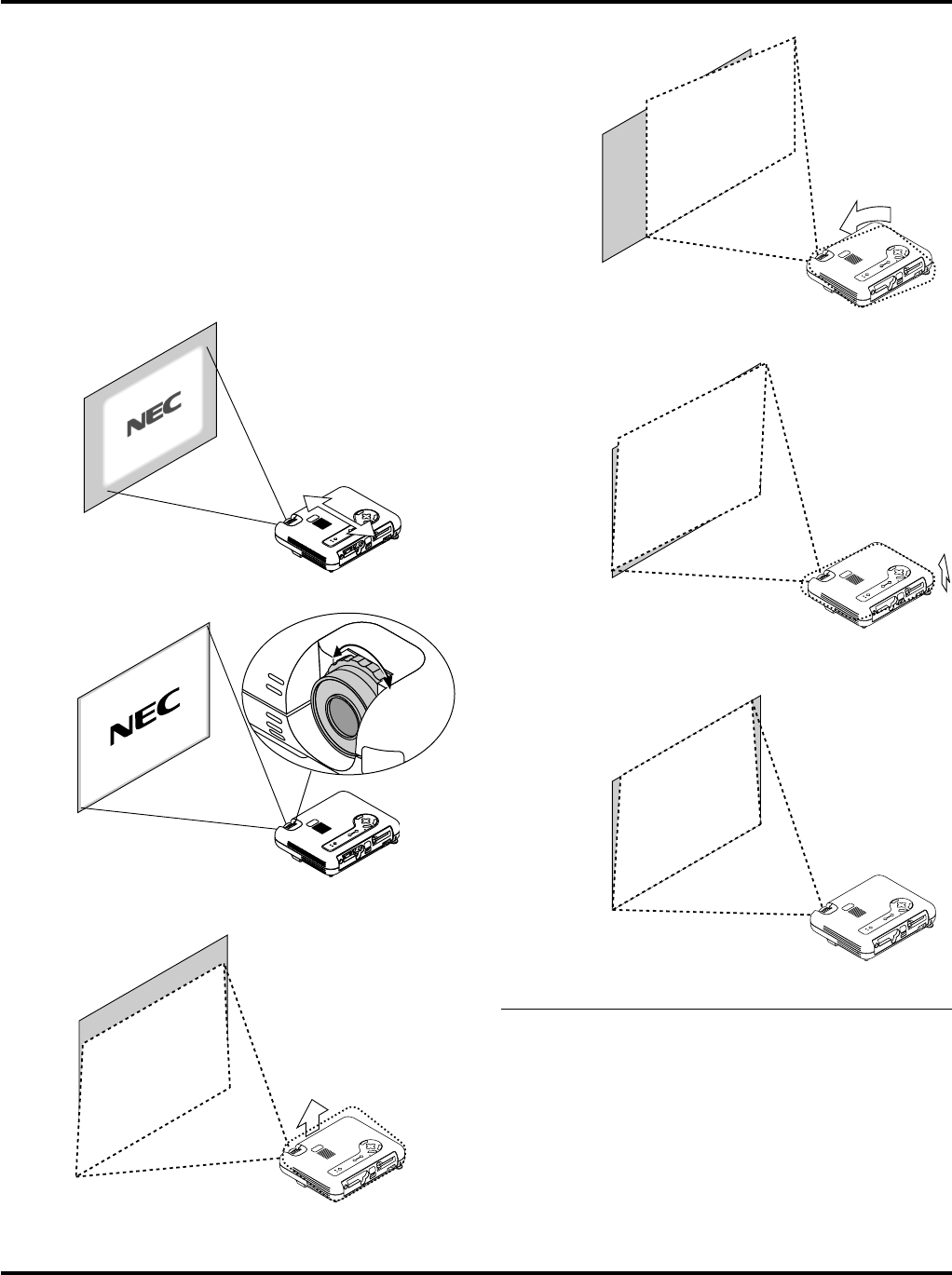
Place your projector on a flat level surface and Ensure
that the projector is square to the screen.
Lift the front edge of the projector to center the image ver-
tically.
Move the projector left to center the image horizontally on
the screen.
Rotate the rear foot to make the image square to the screen.
Use keystone correction for proper adjustment.
E–29
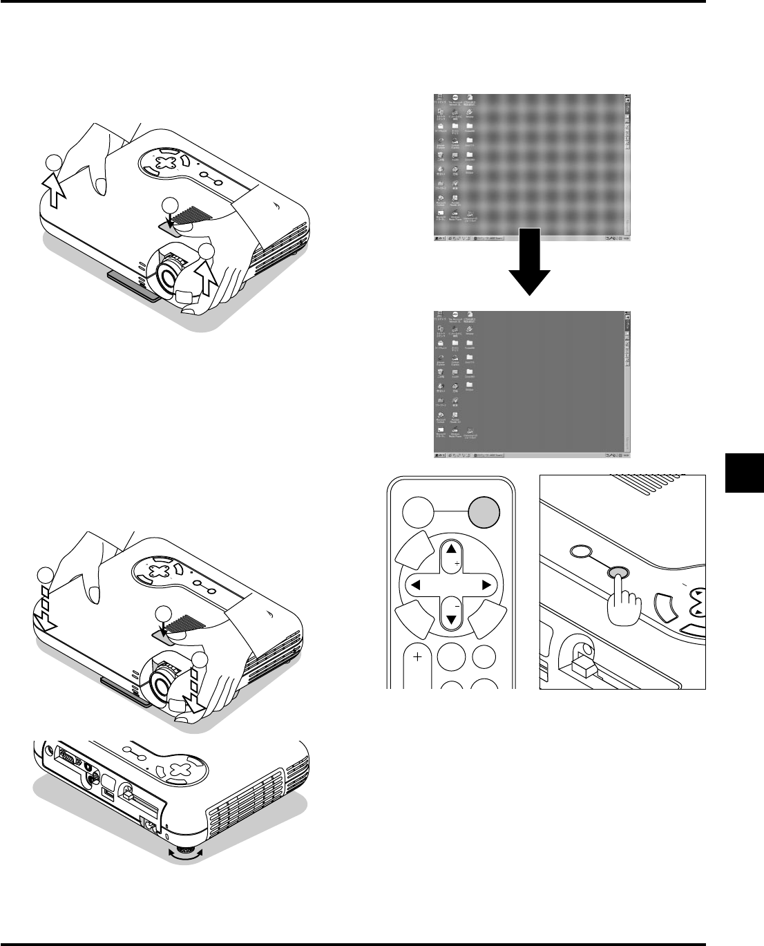
Adjust the Tilt Foot
1)Lift the front edge of the projector.
2)Press the Tilt button on the top of the projector to extend the
adjustable tilt foot (maximum height).
M
E
N
U
E
N
T
E
R
C
A
N
C
E
L
SELECT
AUTO
ADJUST
PC CARD ACCESS
STATUS
POWER
ON/ STAND BY
SOURCE
1
1
2
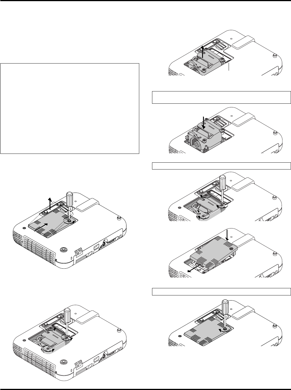
3)Press and hold the Tilt button.
4)Lower the front of the projector to the desired height and re-
lease the button to lock the Adjustable tilt foot.
There is approximately 5 degrees of up and down adjustment
for the front of the projector. The rear foot height can be changed,
but the vertical distance from the bottom to the desk or floor
should be 0.14 ” (3.5mm) to make the projector horizontal on
the flat surface. To fine-adjust the height of the rear foot, re-
move the spacer (black rubber) and rotate the rear foot to the
desired height.
*If the projected image does not appear square to the screen
then use keystone correction for proper adjustment.
M
E
N
U
E
N
T
E
R
C
A
N
C
E
L
SELECT
AUTO
ADJUST
PC CARD ACCESS
STATUS
POWER
ON/ STAND BYSOURCE
4
4
3
updown
Adjust the Image Using Auto Adjust
The Auto Adjust function automatically optimizes the image in RGB
mode.
[Poor picture]
[Normal picture]
Press the Auto Adjust button to adjust Position-H/V and Pixel Clock/
Phase for an optimal picture. Some signals may not be displayed
correctly or take time to switch between sources.
PC CA
RD
E
N
T
E
R
C
A
N
C
S
AUTO
ADJUST
PC CARD ACCESS
SOURCE
SELECT
Vol.
Vol.
POINTER
PIC.
MUTE
MAGNIFY
SOURCE
AUTO
ADJ.
M
E
N
U
E
N
T
E
R
C
A
N
C
E
L
Do not use the tilt-foot for purposes other than originally intended.
Misuses such as gripping the tilt-foot or hanging on the wall can
cause damage to the projector.
E–30
Basic Operation
SOURCE
AUTO
ADJ.
Selecting the computer or video source
Source display
SOURCE
AUTO
ADJ.
Optimizing RGB image automatically
Press the Auto Adjust button to optimize an RGB image automati-
cally.
Press the Auto Adjust button to fine-tune the computer image or to
remove any vertical banding that might appear and to reduce video
noise, dot interference or cross talk (this is evident when part of your
image appears to be shimmering). This function adjusts the clock
frequencies that eliminate the horizontal banding in the image. This
function also adjusts the clock phase to reduce video noise, dot inter-
ference or cross talk. (This is evident when part of your image ap-
pears to be shimmering.)
This adjustment may be necessary when you connect your computer
for the first time.
NOTE: The Auto Adjust function does not work for component signal.
Each time the Source button is pressed, the input source will change
as follows:
→ RGB → Video → S-Video → PC Card Viewer
If no input signal is present, the input will be skipped.
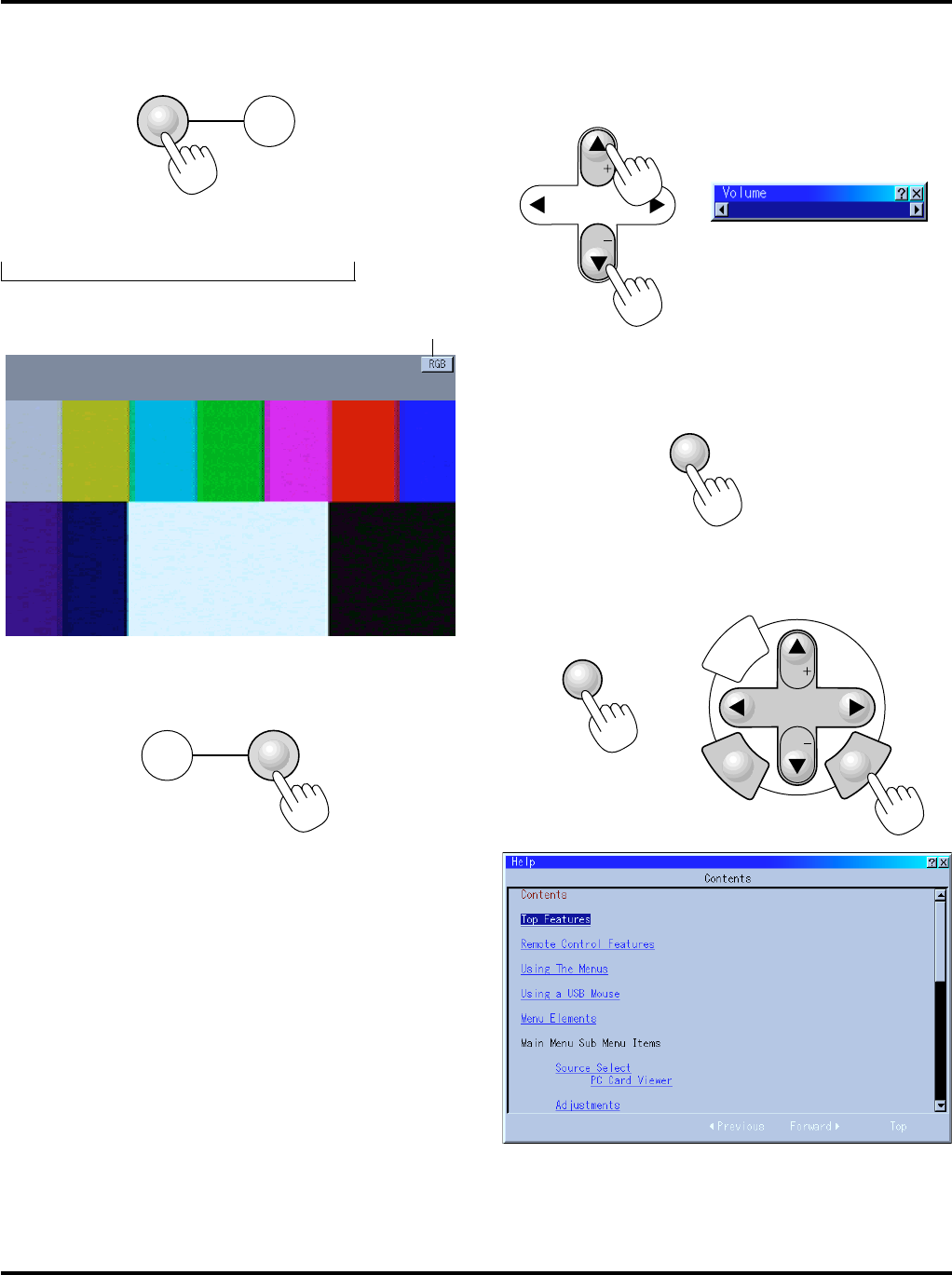
Turning off picture and sound
Press the Picture Mute button to turn off the image and sound for a
short period of time. Press again to restore the image and sound.
PIC.
MUTE
Getting Help about how to operate the projector
You get the contents about Help.
SELECT
Vol.
Vol.
M
E
N
U
E
N
T
E
R
C
A
N
C
E
L
HELP
SELECT
Vol.
Vol.
increase volume
decrease volume
Volume bar
Volume control
Sound level from the speaker on the projector can be adjusted.
NOTE: When the menu or the pointer appears, you cannot adjust the volume.
Display Help
Exit Help
E–31
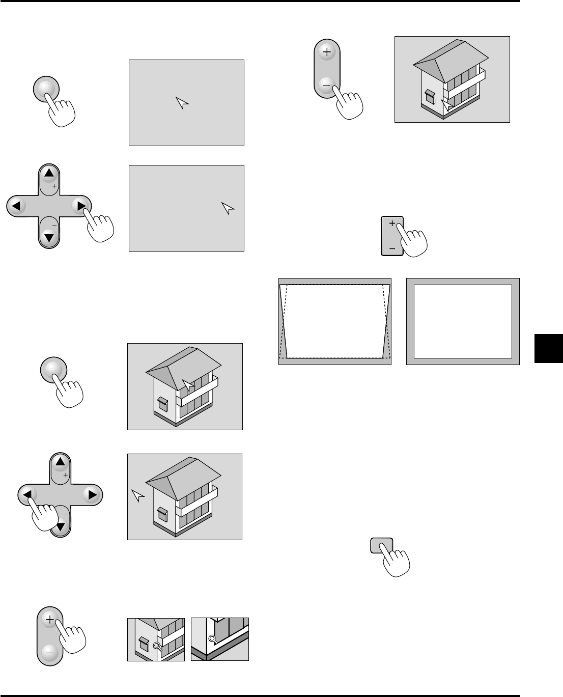
Using Pointer
You can use one of eight pointers to draw your audience's attention to
the portion of a projected image you want.
POINTER
SELECT
Vol.
Vol.
Press the Pointer button to
display the pointer.
Use the Select button to move
the pointer.
Enlarging and Moving a Picture
You can enlarge the area you want up to 400 percent.
To do so:
1.Press the Pointer button to display the pointer.
SELECT
Vol.
Vol.
MAGNIFY
MAGNIFY
KEYSTONE
FREEZE
POINTER
2.Move the pointer to the area you want to enlarge.
3.Enlarge the selected area.
When the Magnify (+) button is pressed, the pointer is changed to
a magnifying glass. To move the magnifying glass, use the Select
button.
4.Return the image to the original size.
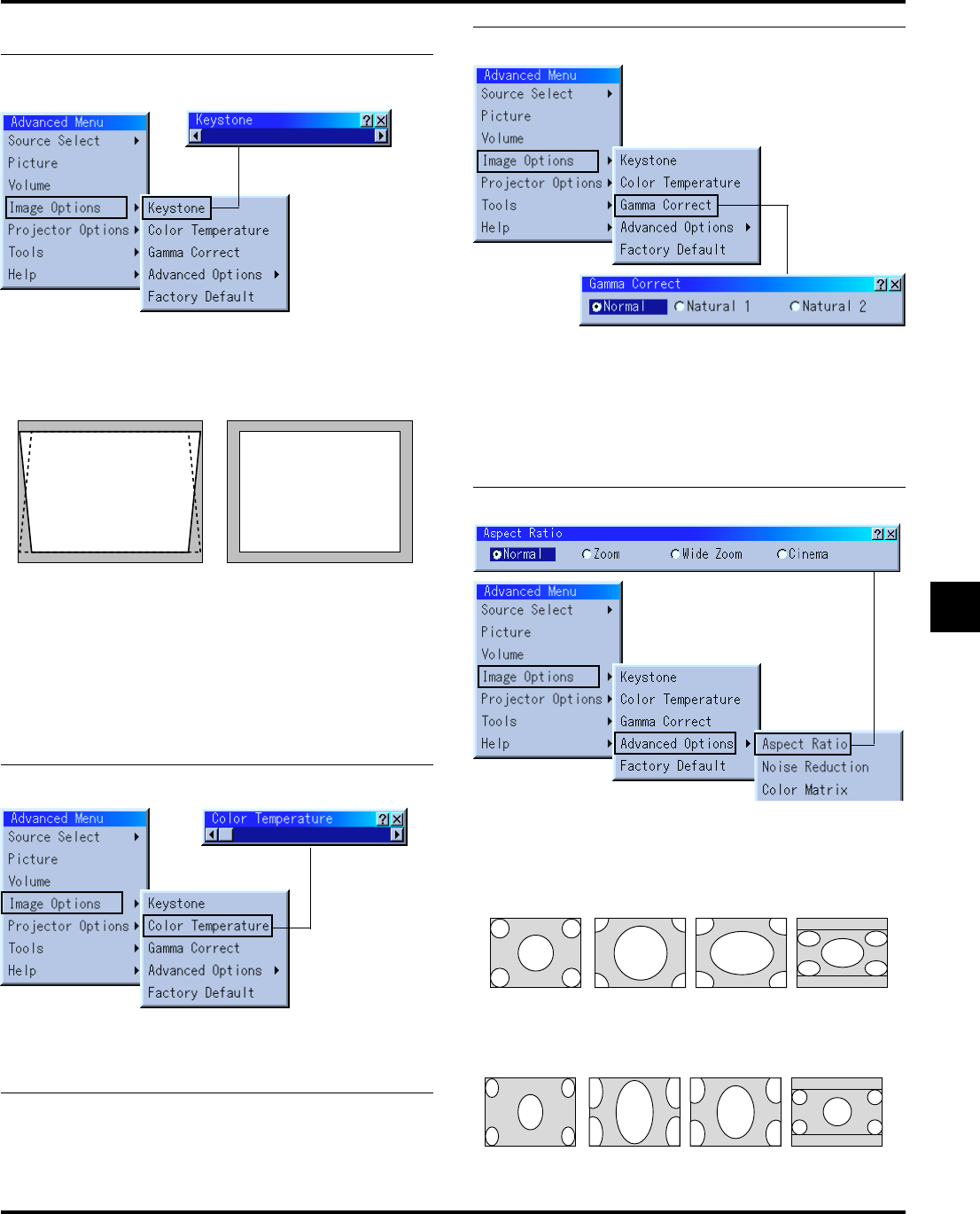
Correcting Keystone distortion
(Optional presentation remote control)
Press (+) or (-) to correct keystone (trapezoidal) distortion to make
the top or bottom of the screen longer or shorter so that the projected
image is rectangular.
Freezing a picture
(Optional presentation remote control)
Press the Freeze button to freeze a picture. Press again to resume
motion.
Keystone distortion
Normal
NOTE: The maximum keystone angle that can be corrected is 45 degrees up-
ward and 15 degrees downward with the projector placed horizontally on the
ground plane.
Depending on the type of graphics being used, the picture may get blurred or
keystone correction may not be possible when excessive keystone correction
is used.
The idea is, the closer you are to native resolution, the better image you will
see.
E–32
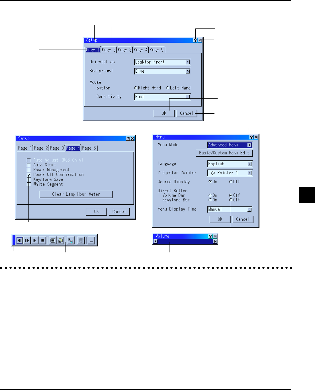
Using the Menus
NOTE: The on-screen menu may not be displayed correctly while interlaced
motion video image is projected.
1.Press the "Menu" button on the remote control or projector cabi-
net to display the Advanced Menu or Basic/Custom Menu.
NOTE: When using a USB mouse, click the mouse button to display the
menu. For other operations, do the same way as you use your PC mouse.
2.Press the ▲▼ buttons on the supplied card remote control or the
projector cabinet, or the optional presentation remote control to
highlight the menu for the item you want to adjust or set.
3.Press the ᮣ button or the "Enter" button on the supplied card re-
mote control or the projector cabinet, or the "Left Click" button
on the optional presentation remote control to select a submenu or
item.
4.Adjust the level or turn the selected item on or off by using "Se-
lect" ᮤ or ᮣ buttons on the supplied card remote control or the
projector cabinet, or the "Mouse pad" on the optional presenta-
tion remote control. The on-screen slide bar will show you the
amount of increase or decrease.
5.Changes are stored until you adjust it again.
ENTER......Stores the setting or adjustments.
CANCEL...Return to the previous screen without storing settings
or adjustments.
NOTE: You can close the main and sub menus simultaneously by pressing
the PJ button on the optional presentation remote control to cancel the
Projector mode.
6.Repeat steps 2-5 to adjust an additional item, or press "Cancel" on
the projector cabinet or the remote control to quit the menu dis-
play.
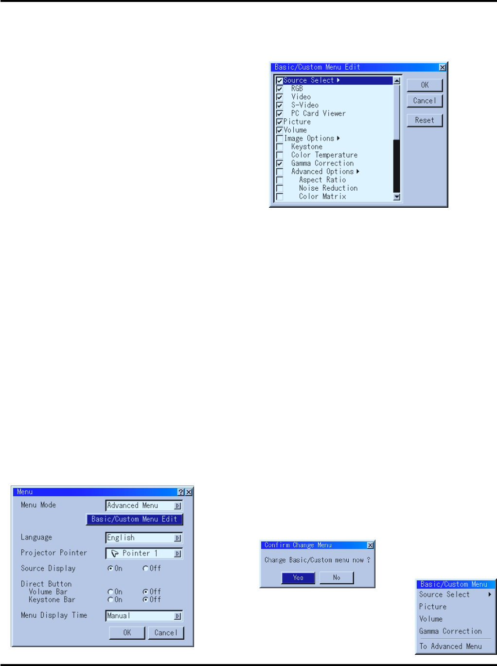
Customizing Basic/Custom Menu
The Basic/Custom menu can be customized to meet your require-
ments. Selecting a menu item from the “Basic/Custom Menu Edit”
list, allows you to custom tailor the menu items to your needs.
1.Select “Basic/Custom Menu Edit” to display the “Basic/Custom
Menu Edit” screen.
2.Use the Select buttons ▲ or ▼ to highlight your selection and
press the Enter button to place a check mark next to an option.
This action enables that feature.
Press the Enter button again to clear the check box.
If you select an item with a solid triangle ᮣ and press the Enter
button on the remote control or the projector cabinet, you can en-
able all the items within that submenu.
Also you can turn on an item within the submenu without placing
a check mark on the main menu item.
NOTE: Up to 12 main menu items (within Basic/Custom Menu Edit, not
including submenu items) can be selected.
3.In order for the changes to take effect, use the ᮤ or ᮣ button on
the remote control or the projector cabinet to highlight “OK”, then
press the Enter button. To cancel the changes, use the Select ▲ or
▼ buttons to highlight “Cancel” and press the “Enter” button. To
return to the factory default, select “Reset” then press the “Enter”
button.
The default Basic/Custom Menu items are:
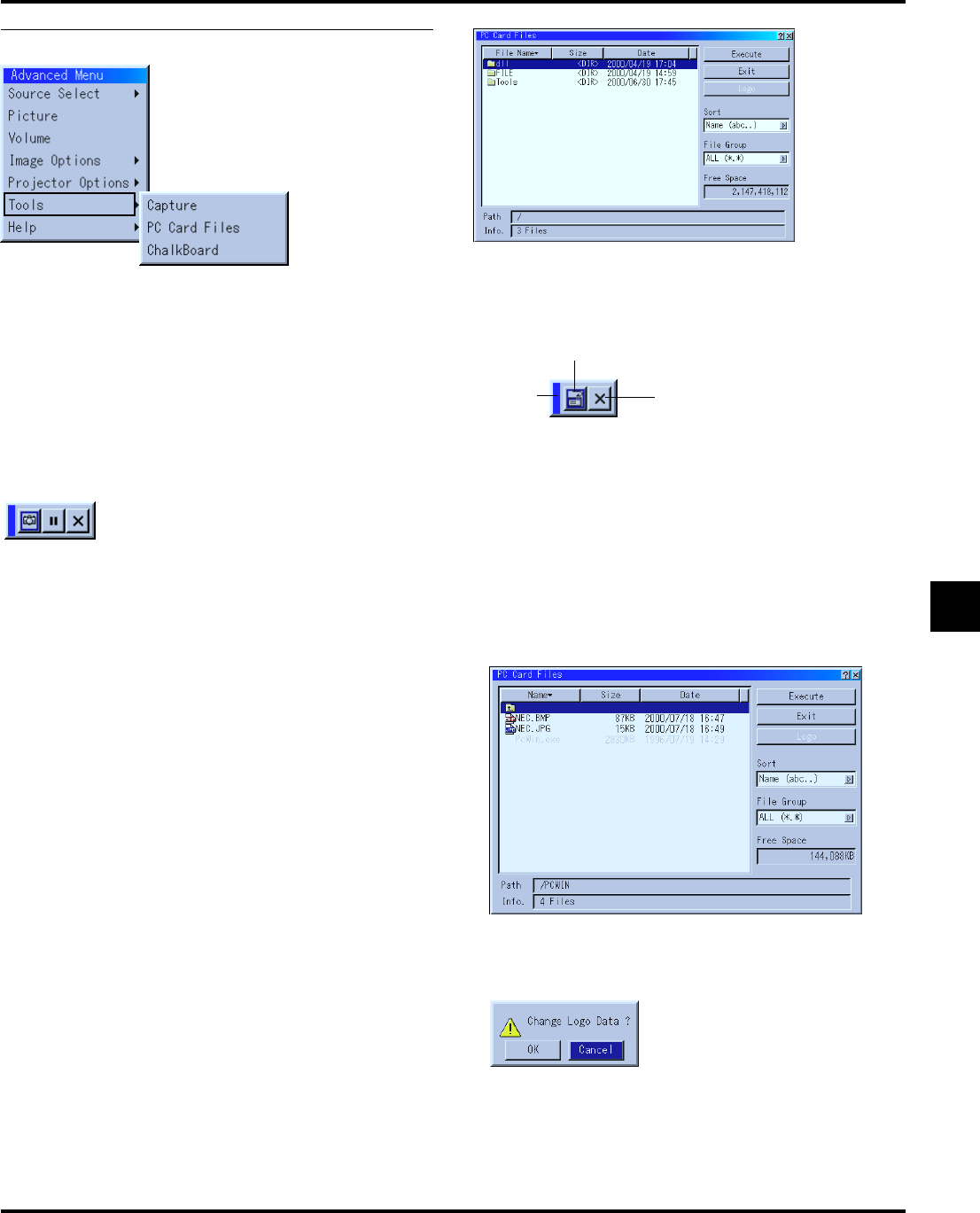
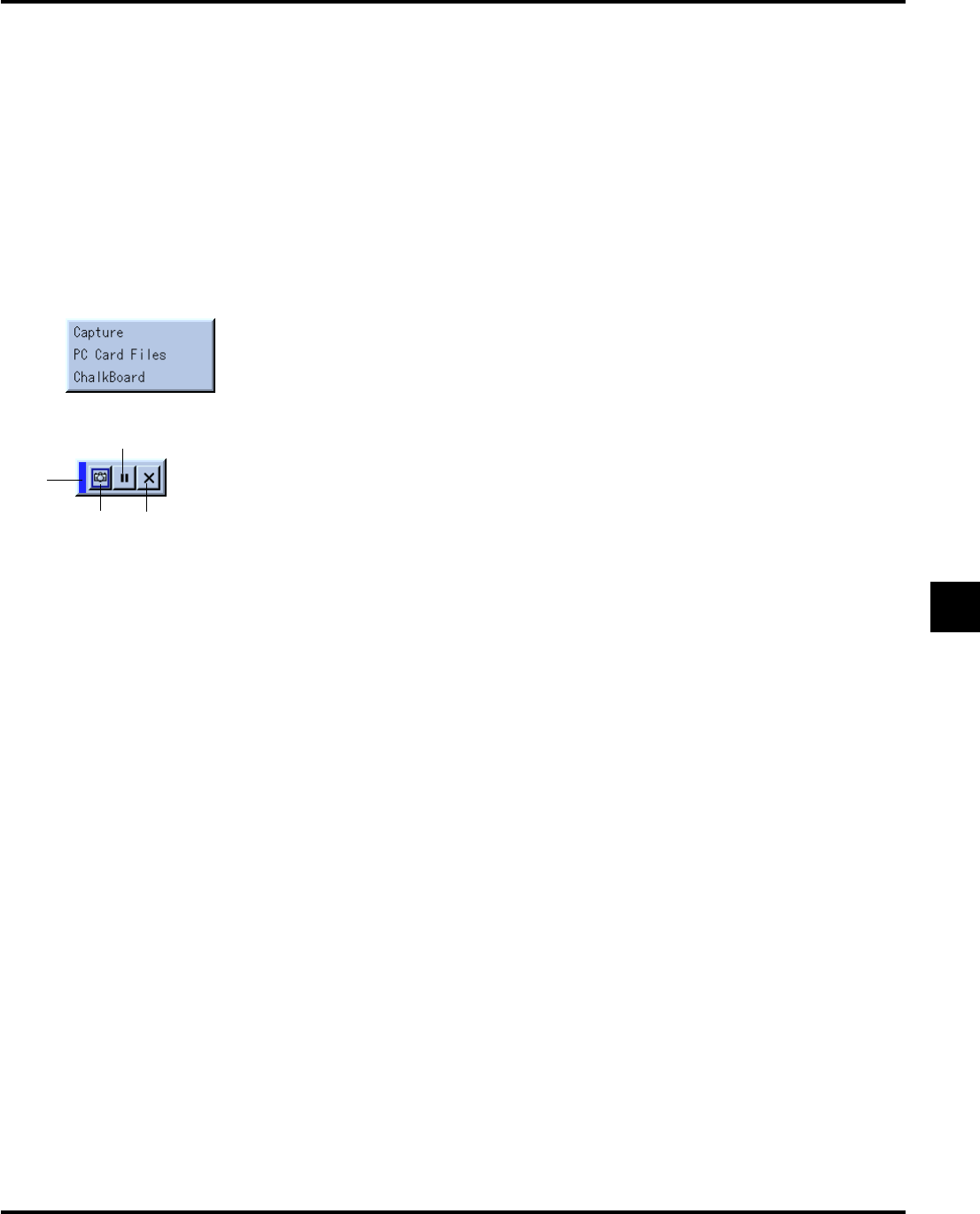
Source Select (RGB, Video, S-Video and PC Card Viewer), Picture, Volume, Image
Options (Keystone and Color Temperature), Projector Options (Menu and Setup), Tools
(Capture, PC Card Files and ChalkBoard) and Help (Contents and Information)
NOTE: Once you have selected OK on the Basic/Custom Menu Edit screen,
you cannot cancel the changes on the Menu screen. However, you can re-edit
the menu items over again as described in the steps above.
NOTE: If the “Advanced Menu” item has been selected on the Menu mode, you get
the “Confirmation Change Menu” upon completion of “Basic/Custom Menu” ed-
iting. In this case, selecting “Yes” then “Enter” will close all the menus and apply
the changes from the Advanced menu to the Basic/Custom Menu.
If you select “No” then “Enter” functions, then all menu items will
return to the Advanced menu, but your changes will still be available within
the “Basic/Custom Menu” selection. To display the previously tailored Basic/
Custom Menu, select “Basic/Custom Menu” from the “Menu Mode”.
An item “To Advanced Menu” will be
added to the bottom of the Basic/Custom
Menu.
Selecting this item and pressing the “En-
ter” button will display the “Advanced
Menu” features.
E–33
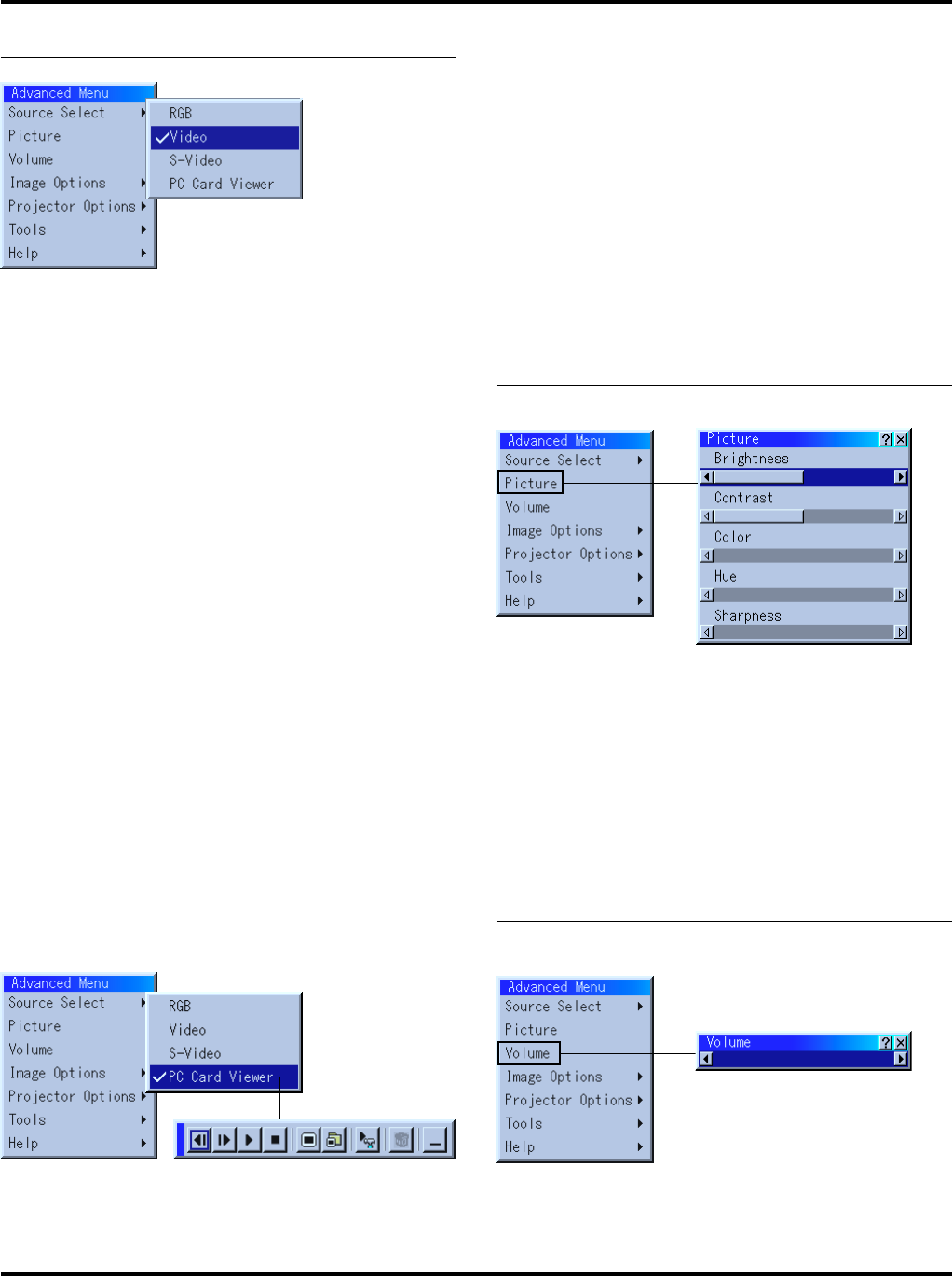
Using a USB Mouse
Using a USB mouse gives you a smooth operation. A commercially
available USB mouse is required.
NOTE:There may be some brands of USB mouse that the projector does not
support.
Operate the Menus using the USB mouse
Mouse Cursor
When connecting a USB mouse to the projector, you get a mouse
cursor on the screen.
Unless you use your USB mouse within 10 seconds, the mouse
cursor disappears.
Menu Display
Clicking with a mouse button displays the menu.
Clicking
displays the pull-down menu.
To close the menu, click anywhere in the background.
Adjusting and Setting Display
You can select a menu item and click with a mouse button to
make adjustments and setting.
Examples
Click (or press and hold) the mouse button ᮤ or ᮣ to adjust the
brightness.
Or click and drag the mouse button on the slide bar horizontally
to adjust it.
To save the adjustments, click
. The display is closed.
If you click anywhere in the background while displaying adjust-
ment and setting menu or dialog box, you will get the main menu
Libble takes abuse of its services very seriously. We're committed to dealing with such abuse according to the laws in your country of residence. When you submit a report, we'll investigate it and take the appropriate action. We'll get back to you only if we require additional details or have more information to share.
Product:
Forumrules
To achieve meaningful questions, we apply the following rules:
First, read the manual;
Check if your question has been asked previously;
Try to ask your question as clearly as possible;
Did you already try to solve the problem? Please mention this;
Is your problem solved by a visitor then let him/her know in this forum;
To give a response to a question or answer, do not use this form but click on the button 'reply to this question';
Your question will be posted here and emailed to our subscribers. Therefore, avoid filling in personal details.
Register
Register getting emails for Nec LT85 at:
new questions and answers
new manuals
You will receive an email to register for one or both of the options.
Get your user manual by e-mail
Enter your email address to receive the manual of Nec LT85 in the language / languages: English as an attachment in your email.
The manual is 1,47 mb in size.
You will receive the manual in your email within minutes. If you have not received an email, then probably have entered the wrong email address or your mailbox is too full. In addition, it may be that your ISP may have a maximum size for emails to receive.
If you have not received an email with the manual within fifteen minutes, it may be that you have a entered a wrong email address or that your ISP has set a maximum size to receive email that is smaller than the size of the manual.
The email address you have provided is not correct.
Please check the email address and correct it.
Your question is posted on this page
Would you like to receive an email when new answers and questions are posted? Please enter your email address.