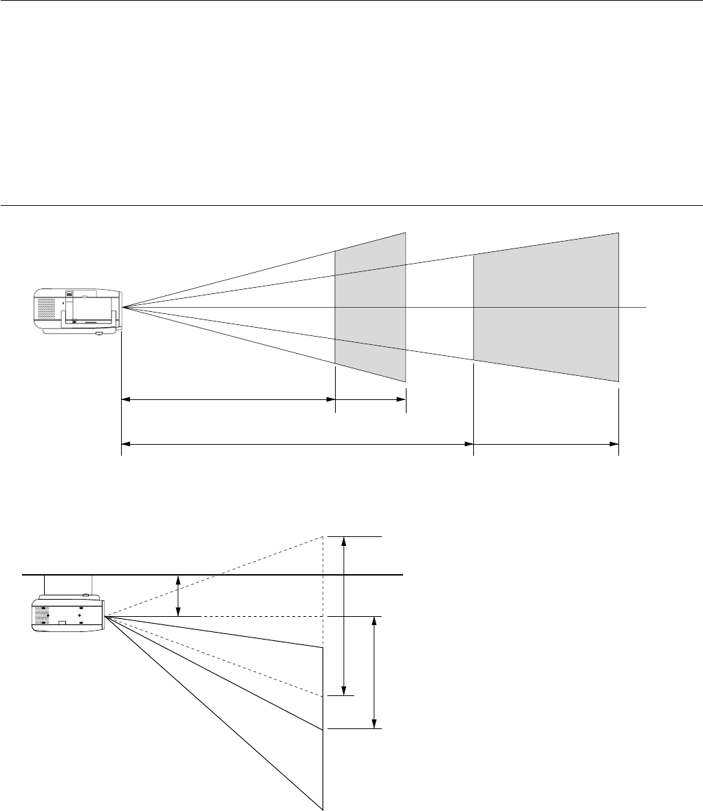
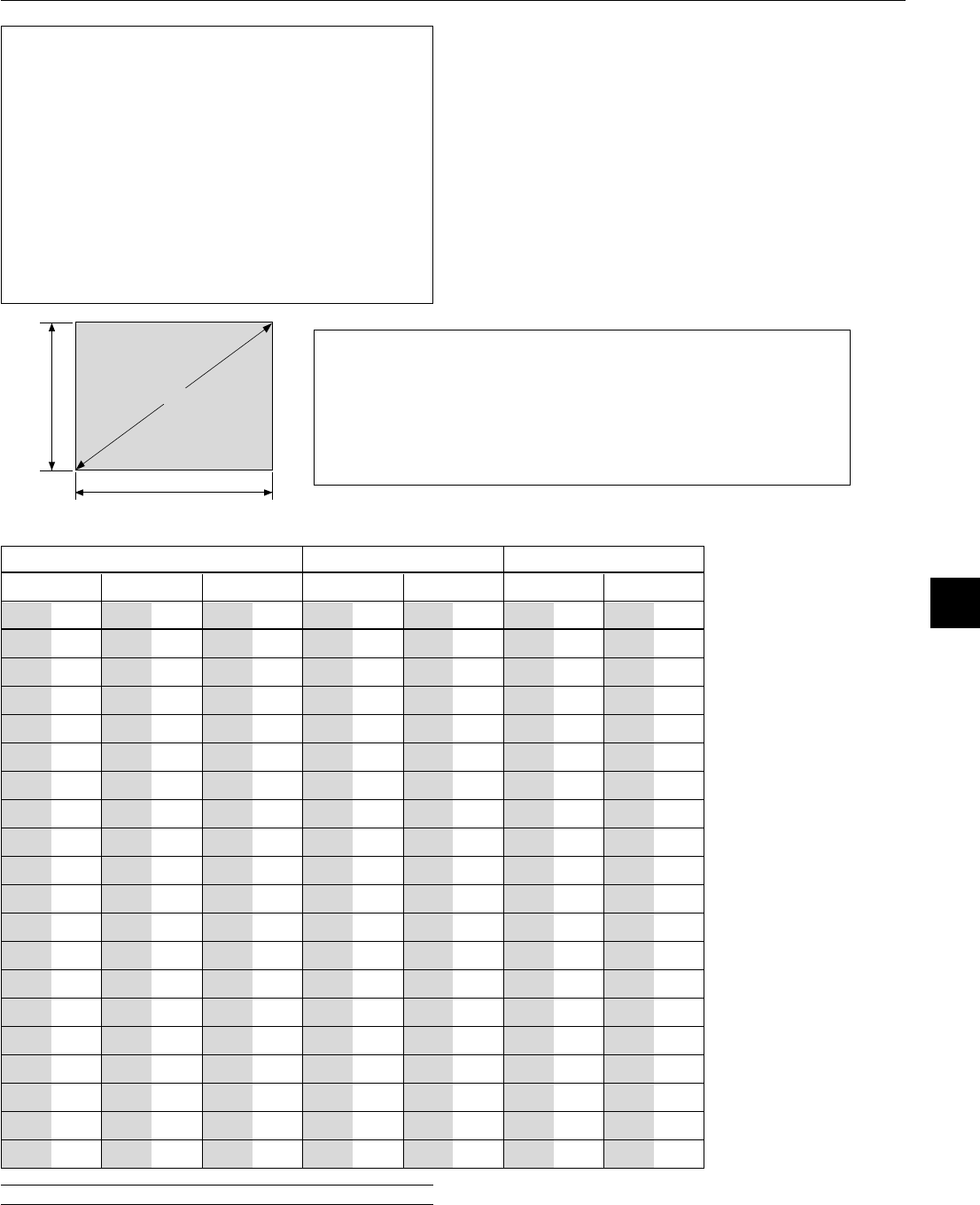
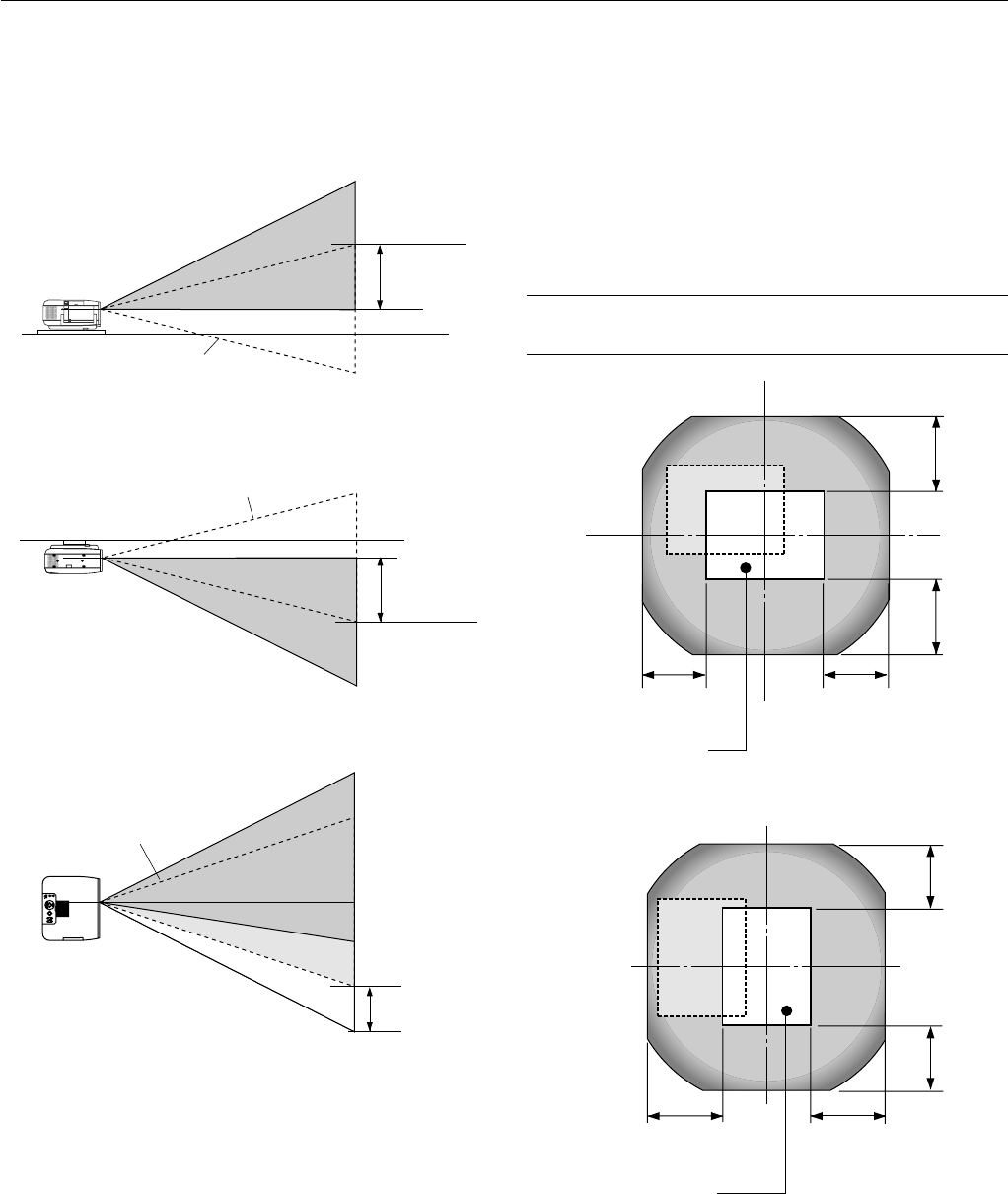
(H: width of projected image, V: height of projected image)
NOTE: If lens is shifted in two directions combined, maximum range in either
direction cannot be obtained due to rounded off area near edge of lens. (ex-
ample: shift up and right) See diagram below.
Lens Shift Range for Desktop and Ceiling Mount Application
The diagram below shows the location of the image position in the
lens. The lens can be shifted within the shaded area as shown using
the normal projection position as a starting point.
The lens can be returned to the default position (factory setting). See
“Zero Position” on page E-47.
0.85V
0.85V
0.55H0.55H
0.85V0.85V
0.55H
0.55H
Portrait
Normal projection position
Normal projection position
E – 21
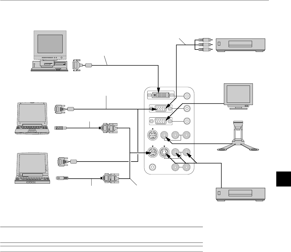
Wiring Diagram
Supplied serial cable
AUDIO IN
AUDIO IN
AUDIO OUT
AUDIO OUT
DVI IN
RGB IN
RGB OUT
PC CONTROL
MOUSE
OUTPUT
REMOTE
CONTROL
INPUT
AUDIO IN
AUDIO IN
R
L/
MONO
VIDEO
S-VIDEO
Supplied signal cable
To mini D-Sub 15-pin connector on the projector. It is
recommended that you use a commercially available distribution
amplifier if connecting a signal cable longer than the supplied one.
PC with DVI output
Macintosh
(Desktop type or notebook type)
IBM VGA or Compatible
(Desktop type or notebook type)
Supplied mouse adapter (USB)
Supplied mouse adapter
(For IBM PS/2 or USB)
DVD Player
(with component output)
Optional 15-pin-to-RCA
(female) x 3 cable
(ADP-CVI)
Monitor
Document Camera
VCR, DVD Player or
LaserDisc Player
To video, S-video, and audio
inputs on the projector.
NOTE:When using with a notebook PC, be sure to connect between the projector and the notebook PC before turning on the
power to the notebook PC. In most cases signal cannot be output from RGB output unless the notebook PC is turned on after
connecting with the projector.
NOTE: If using video, S-video, or audio cables, the cables should be 3 m (9.8 feet) or shorter.
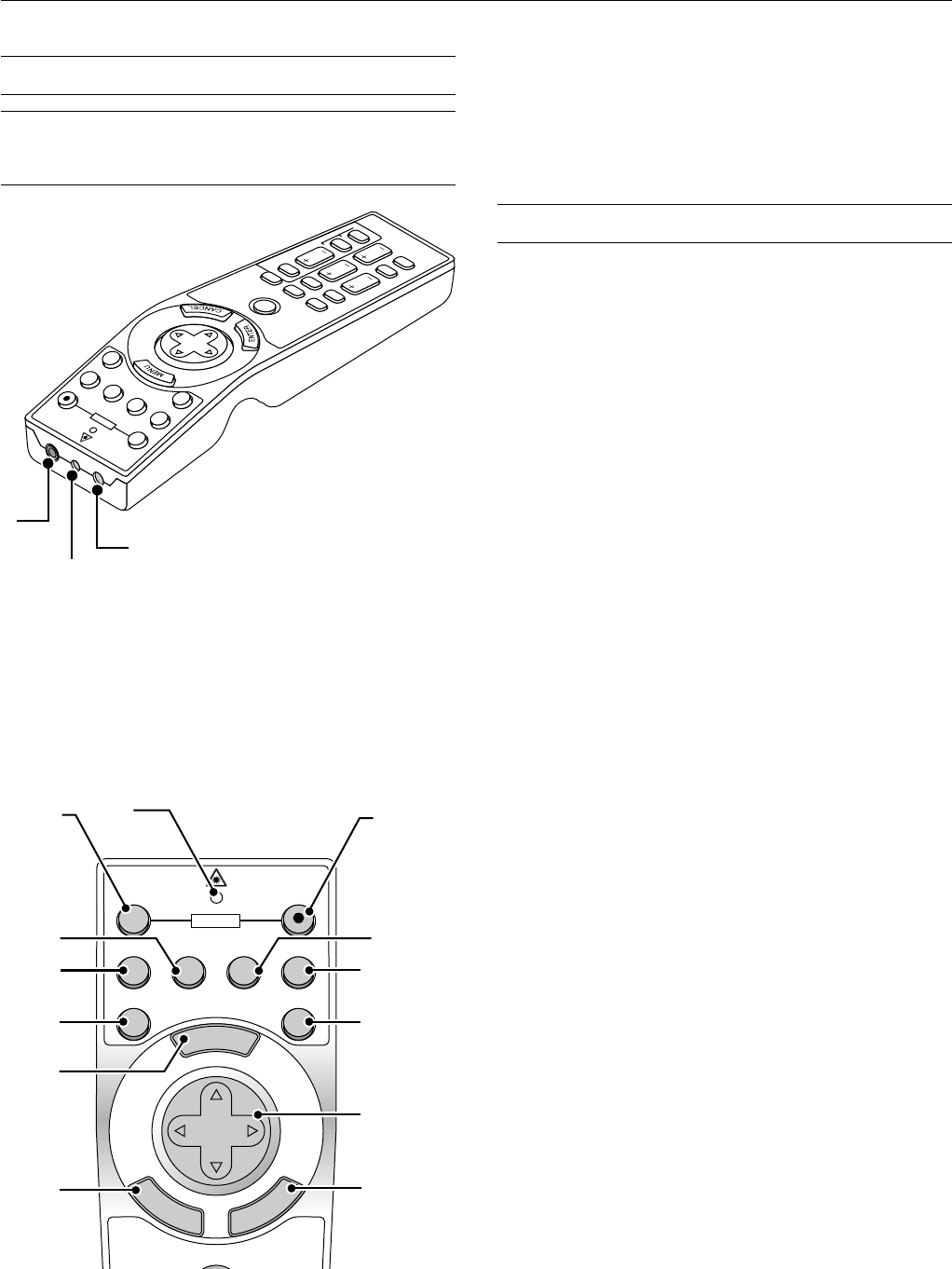
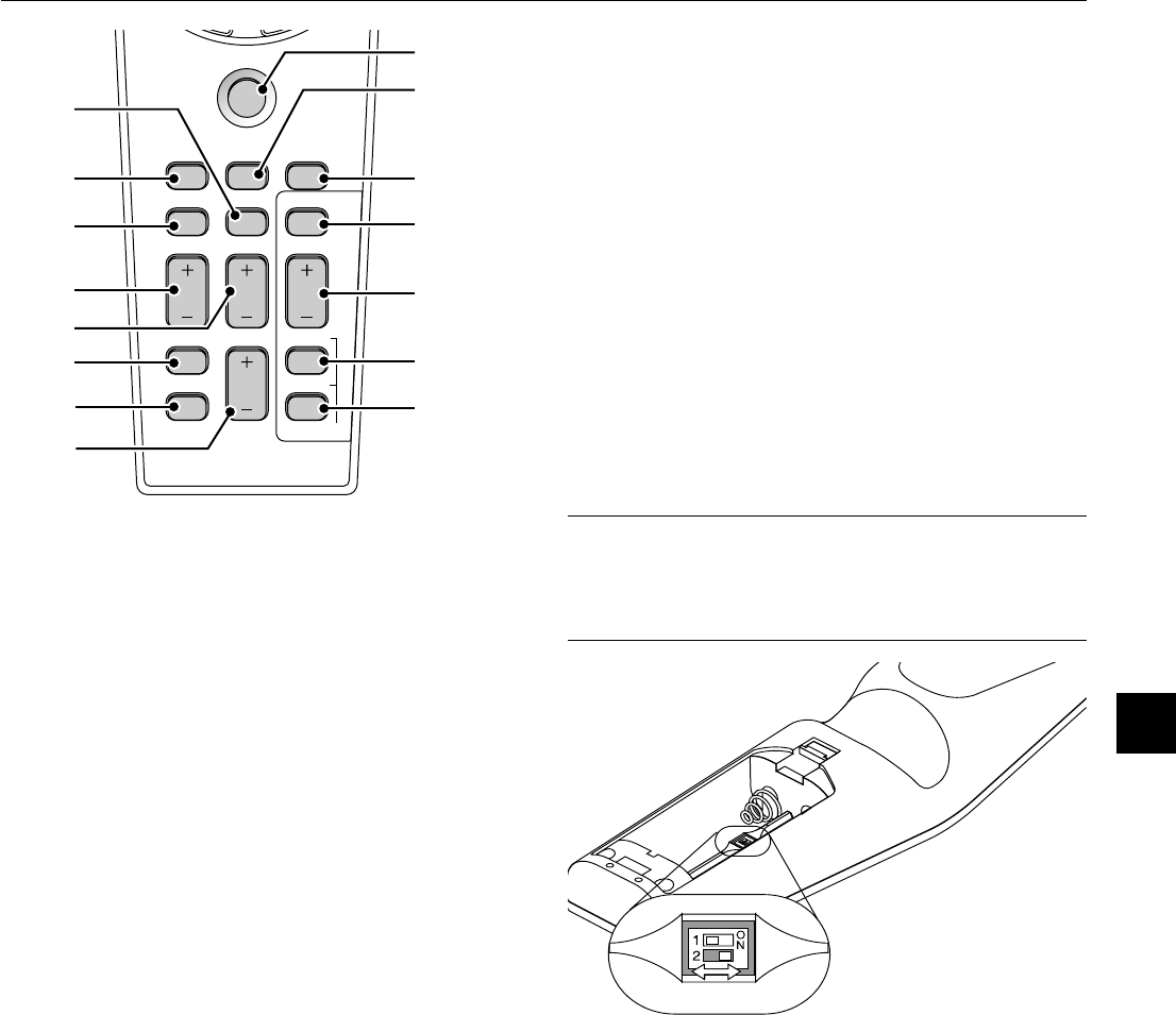
Remote Control Guideline
1.Plug the supplied serial cable with the mouse output port of the projector into your computer’s mouse port
and restart your computer to gain remote mouse control.
2.When using the remote control’s built-in infrared mouse on a laptop computer, the laptop’s mouse, trackball
or trackpad will be disabled. Disconnect the serial cable from the mouse output port and restart your com-
puter to regain trackball or trackpad mouse control.
3. If the screen goes blank while using your remote control, it may be the result of the computer’s screen-saver
or power management software.
4. If you accidentally hit the OFF button on the remote control, wait 2 full minutes and then press the ON button
to resume.
DVI cable (not supplied)
E – 22
AUDIO IN
AUDIO IN
AUDIO OUT
DVI IN
RGB IN
RGB OUT
PC CONTROL
R
L/
MONO
VIDEO
DVI IN
AUDIO IN
RGB IN
AUDIO IN
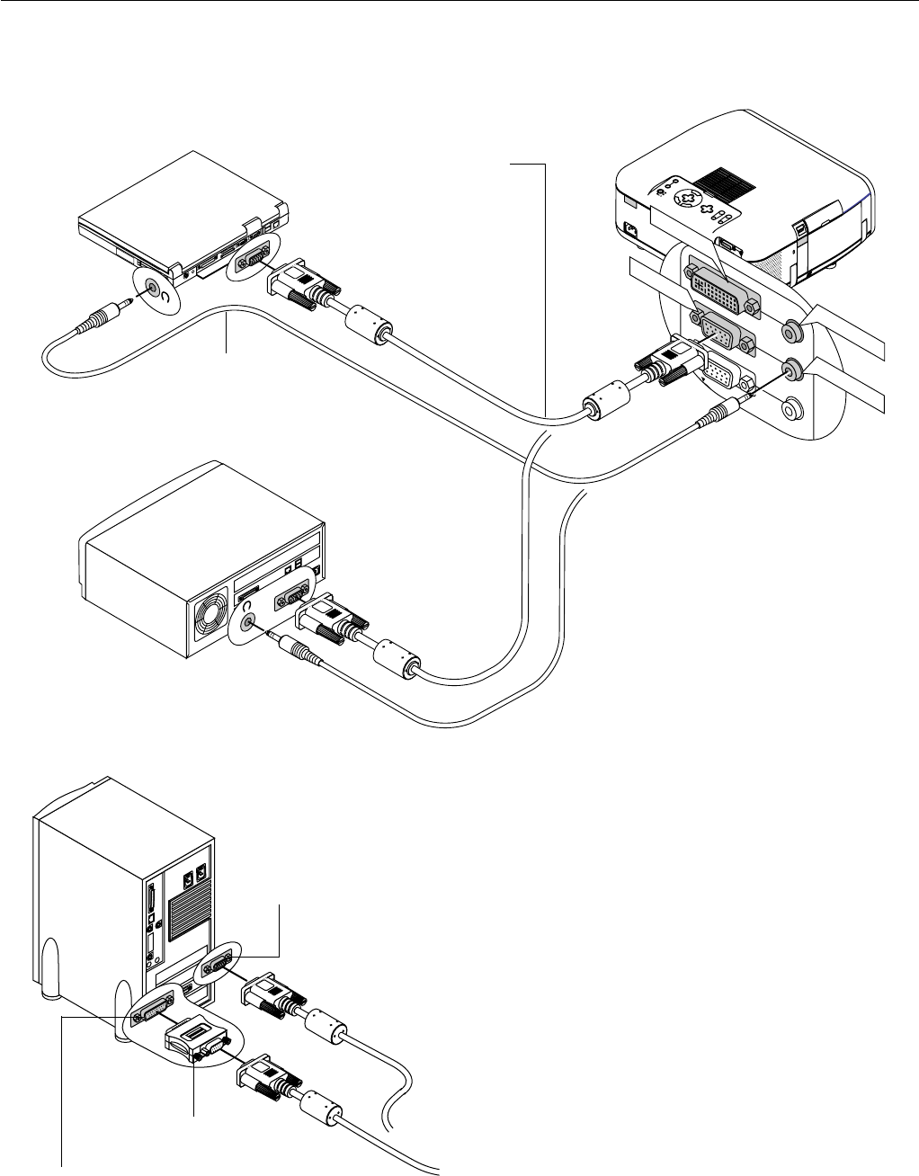
Connecting Your PC or Macintosh Computer
Connecting your PC or Macintosh computer to your GT950 projector
will enable you to project your computer’s screen image for an impres-
sive presentation.
To connect to a PC or Macintosh, simply:
1.Turn off the power to your projector and computer.
2. Use the signal cable that’s supplied to connect your PC or Macintosh
computer to the projector.
3.Turn on the projector and the computer.
4.If the projector goes blank after a period of inactivity, it may be caused
by a screen saver installed on the computer you’ve connected to the
projector.
IBM VGA or Compatibles (Notebook type)
or
Macintosh (Notebook type)
Audio cable
(not supplied)
RGB signal cable (supplied)
To mini D-Sub 15-pin connector on the
projector. It is recommended that you use
a commercially available distribution
amplifier if connecting a signal cable
longer than the supplied one.
IBM VGA or Compatibles (Desktop type)
1
O
N
D
I
P
2
3
456
Pin adapter for Macintosh
(not supplied)
For older Macintosh, use a commercially
available pin adapter to connect to your
Mac's video port.
The new Macintosh computer such as
G3 will have the 15 pin HD connec-
tor. The GT950's "Plug and Play" data
will be downloaded to the Macintosh.
Therefore, a Mac adapter will not be
necessary.
Macintosh (Desktop type)
E – 23
PUT
AUDIO OUTPUT
AUDIO OUT
UTPUT
PC CONTROL
MOUSE
OUTPUT
REMOTE
CONTROL
INPUT
AUDIO IN
AUDIO IN
R
L/
MONO
VIDEO
S-VIDEO
MOUSE
OUTPUT
Serial cable (supplied)
Macintosh with USB
Port
IBM PS/2
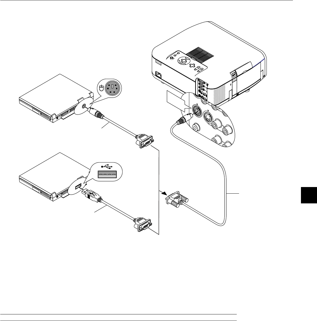
The built-in remote mouse receiver enables you to operate your computer's mouse functions from the remote control. It
is a great convenience for clicking through your computer-generated presentations.
To connect the mouse output port:
1. Turn off your computer.
2. For PCs: Remove your current mouse and connect the supplied serial cable from the mouse output to your PC's
mouse port. (Use the 6-pin adapter for connecting to a PS/2 computer or the supplied USB adapter.)
For Macintosh: Attach the supplied mouse adapter for USB to the mouse output port's serial cable and connect the
projector to your USB port of a Macintosh computer.
3. When the built-in remote mouse receiver is available, it will disable your regular mouse, disconnect the serial cable
and restart your computer.
NOTE: The mouse adapter for USB is not compatible with the USB terminal on the projector.
Connecting Your Computer to the Mouse Output Port
Mouse adapter
(For IBM PS/2)
(supplied)
Mouse adapter (USB)
(supplied)
E – 24
AUDIO
A
U
D
IO
IN
A
U
D
IO
IN
P
U
T
A
U
D
IO
O
U
T
A
DVI IN
RGB IN
RGB OUT
PC CONTROL
MOUSE
OUTPUT
REMOTE
CONTROL
INPUT
AUDIO IN
AUDIO IN
R
L/
M
ON
O
VIDEO
S-VIDEO
RGB OUT
RGB IN
DVI IN
External monitor
RGB Signal
cable
(supplied)
Connecting an External Monitor
To RGB INPUT
You can connect a separate, external monitor to your GT950 projector
to simultaneously view on a monitor the RGB analog, DVI analog, or
component image you're projecting. To do so:
1.Turn off the power to your projector, monitor and computer.
2.Use a 15-pin cable to connect your monitor to the RGB OUT (Mini
D-Sub 15 pin) connector on your projector.
3.Turn on the projector, monitor and the computer.
NOTE:
*The RGB OUT connector outputs RGB signal during standby. When the pro-
jector goes into standby, the image on an external monitor disappears for a
moment.
*The DVI digital output signal from the RGB OUT connector is muted.
*When attaching two D-Sub connector cables to the RGB IN and the RGB
OUT connectors simultaneously, use a cable with connector sizes of 39 mm
x 16 mm (1.53" x 0.63")or less to keep the two connectors from making
contact with each other.
Connecting a PC with DVI output
The DVI input accepts up to the XGA@60Hz signal.
NOTE: The Auto Adjust feature does not work for DVI digital signal. When DVI
signal is selected and the image position is not corrected, adjust the horizontal
and vertical position using the Position/Clock screen. See page E-40 for more
details.
AUDIO IN
AUDIO IN
AUDIO OUT
AUDIO OUT
DVI IN
RGB IN
RGB OUT
PC CONTROL
MOUSE
OUTPUT
REMOTE
CONTROL
INPUT
AUDIO IN
AUDIO IN
R
L/
MONO
VIDEO
S-VIDEO
DVI cable (not supplied)
To DVI digital or
DVI analog
When Viewing a DVI Digital Signal:
To project a DVI digital signal, be sure to connect the PC and the pro-
jector using a DVI-D signal cable (not supplied) before turning on your
PC or projector. Failure to do so may not activate the digital output of
the graphics card resulting in no picture being displayed. Should this
happen, restart your PC.
Do not disconnect a DVI-D signal cable while the projector is running.
If the DVI-D signal cable has been disconnected and then re-connected,
an image may not be correctly displayed. Should this happen, restart
your PC.
E – 25
R L
AUDIO IN
AUDIO IN
AUDIO OUT
D
VI-I IN
R
GB IN
RGB OUT
PC CO
NTRO
L
R
L/
MONO
VIDEO
RGB IN
Y Cb Cr
R L
AUDIO
Component
AUDIO
Red
White
Y
Cb
Cr
Red
White
DVD player
Optional 15-pin-to-RCA (female)ן3 cable
(ADP-CV1)
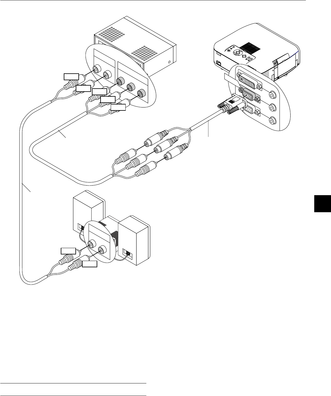
Connecting Your DVD Player
You can connect your projector to a DVD player with component out-
puts or Video output. To do so, simply:
1.Turn off the power to your projector and DVD player.
2. If your DVD player has the component video (Y,Cb,Cr) output, use a
commercially available component video cable (RCAן3) and the
optional 15-pin-to-RCA (female)ן3 cable to connect your DVD player
to the RGB INPUT connector on the projector.
For a DVD player without component video (Y,Cb,Cr) outputs, use
common RCA cables (not provided) to connect a composite VIDEO
output of the DVD player to the Video Input of the projector.
3.Turn on the projector and DVD player.
NOTE: Refer to your DVD player’s owner’s manual for more information about
your DVD player’s video output requirements,
Audio cable
(not supplied)
Component video cable
RCAן3 (not supplied)
Audio Equipment
E – 26
IN
AUDIO IN
AUDIO OUT
AUDIO OUT
NPUT
RGB OUTPUT
PC CONTROL
MOUSE
OUTPUT
REMOTE
CONTROL
INPUT
AUDIO IN
AUDIO IN
R
L/
M
O
N
O
VIDEO
S-VIDEO
R L
S-VIDEO
AUDIO OUT
R L
AUDIO IN
VIDEO
AUDIO IN
AUDIO IN
AUDIO OUT
S-VIDEO
VIDEO
VCR/ Laser disc player
S-video cable (not supplied)
Audio equipment
Audio cable (not supplied)
Document camera
Video cable (not supplied)
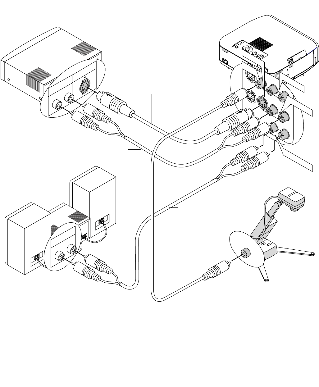
Connecting Your VCR or Laser Disc Player
Use common RCA cables (not provided) to connect your VCR, laser disc player or document camera to your projector.
To make these connections, simply:
1.Turn off the power to the projector and VCR, laser disc player or document camera.
2. Connect one end of your RCA cable to the video output connector on the back of your VCR or laser disc player, connect the other end to the Video
input on your projector. Use an audio cable (not supplied) to connect the audio from your VCR or laser disc player to your audio equipment (if your
VCR or laser disc player has this capability). Be careful to keep your right and left channel connections correct for stereo sound.
3.Turn on the projector and the VCR or laser disc player.
NOTE: Refer to your VCR or laser disc player owner’s manual for more information about your equipment’s video output requirements.
E – 27
SOURCE
SELECT
LEN
S
S
STATUS
POWER
ON/STAND BY
AUTO
ADJUST
M
E
N
U
E
N
T
E
R
C
A
N
C
E
L
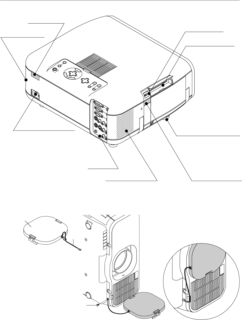
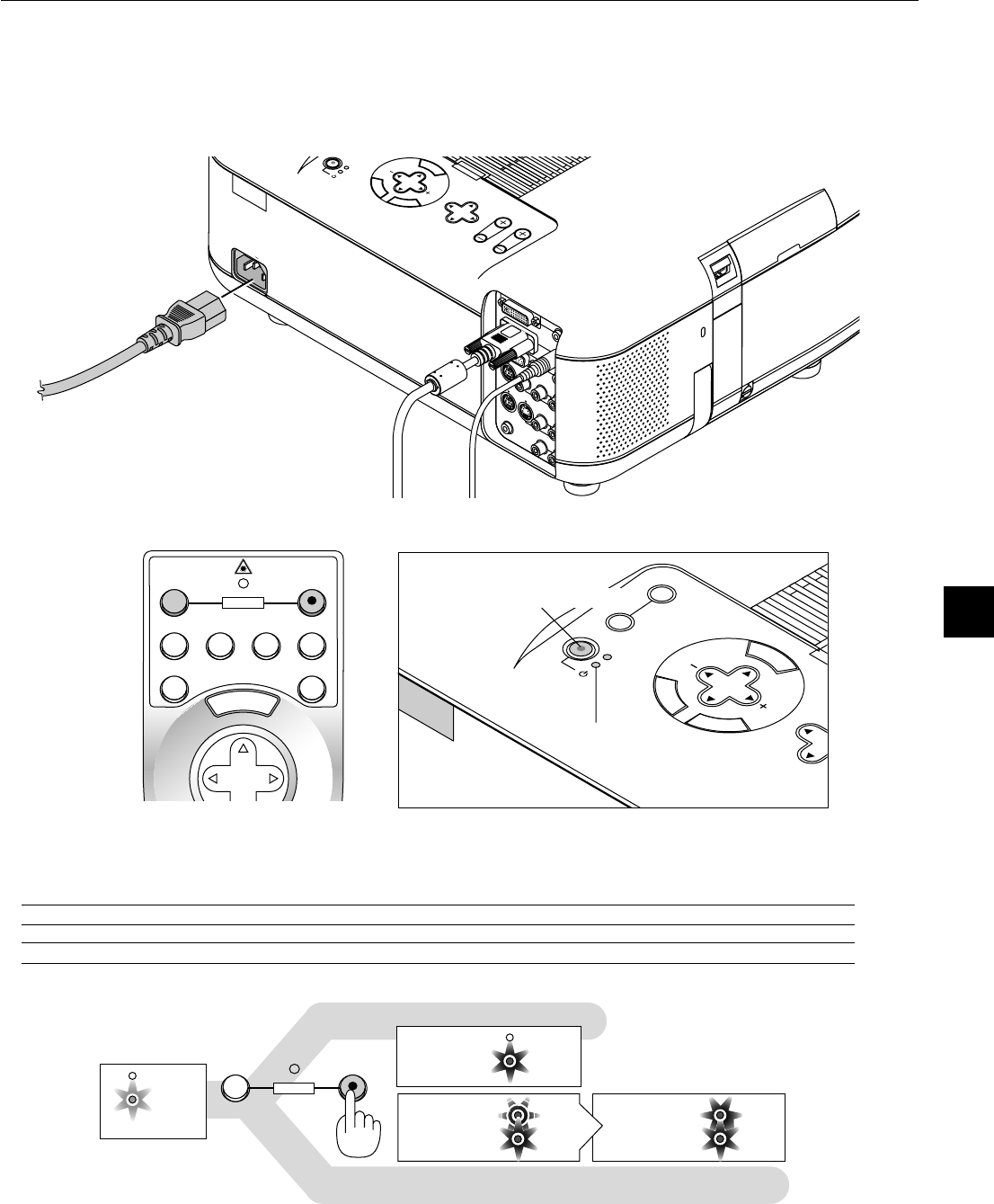
Connecting the Power Cable and Turning on the Projector
Before you turn on your projector, ensure that the computer or video source is turned on and that your lens hood cap is removed.
1.Connect the supplied power cable to the projector.
Plug the supplied power cable in the wall outlet. The projector will go into its standby mode and the power indicator will glow orange.
2.Turn on and off the Projector.
To turn on the projector:
Only after you press the "ON/STAND BY" button on the projector cabinet or "POWER ON" button on the remote control will the power
indicator turn to green and the projector become ready to use.
NOTE: To turn the projector on by plugging in the power cable, use the menu and enable the "Auto Start" feature. (See page E-45.)
NOTE: Immediately after turning on the projector, screen flicker may occur. This is not a fault. Wait 3 to 5 minutes until the lamp lighting is stabilized.
Indicators
POWER
STATUS
POWER
STATUS
POWER
STATUS
POWER
STATUS
OFFON
POWER
S
ELE
CT
LENS SHIFT
FO
C
U
S
ZO
O
M
S
TA
T
U
S
P
O
W
E
R
O
N
/S
TA
N
D
B
Y
U
TO
AD
JU
ST
M
E
N
U
E
N
T
E
R
C
A
N
C
E
L
AC IN
AUDIO INPU
AUDIO INPU
AUDIO OUTP
AUDIO OUTPUT
DVI-I INPUT
RGB INPUT
RGB OUTPUT
PC CONTROL
MOUSE
OUTPUT
REMOTE
CONTROL
INPUT
AUDIO INPUT
AUDIO INPUT
R
L/
MONO
VIDEO
S-VIDEO
M
E
N
U
OFF
VIDEO
AUTO ADJ.
S-VIDEORGB1RGB2
LASER
ON
SELECT
POWER
Power "ON/STAND BY" button
Status of Indicators:
Stand by
Steady orange light
Lamp Mode:
Normal mode
Lamp Mode:
Eco mode
Steady light
Flashing green light
Steady green light
Flashing 3 minutes.
During this time Normal mode is
forcefully selected.
Steady green light
Steady green light
This section describes how to select a computer or video source, how to adjust the picture, and how to customize the menu or projector settings.
3. OPERATION
E – 28
POWER
STATUS
POWER
STATUS
OFFON
POWER
Status of Indicators: OFF
Fan running
Stand by
Flashing green
light
Steady orange
light
To turn off the projector:
First press the Power (ON/STANDBY) button on the projector cabinet or the POWER OFF button on the remote control for a minimum of two
seconds. The power indicator will glow orange. After the projector turns off, the cooling fans keep operating for 2 minutes.
NOTE: Do not disconnect the power cable during this time.
Then, unplug the power cable. The power indicator will go out.
M
E
N
U
E
N
T
E
R
C
A
N
C
E
L
PJ
FOCUSZOOM
OFF
VIDEO
AUTO ADJ.
S-VIDEORGB1RGB2
LASER
ON
VOLUME
SHIFT
HELP
POINTER
KEYSTONE
MAGNIFY
FREEZE
PIC-MUTE
PC CARD
SLIDE
FOLDER
SLIDE
LIST
SELECT
POWER
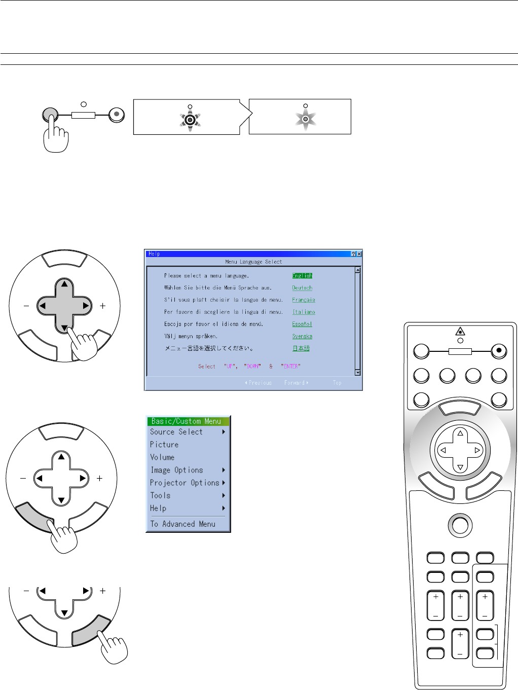
About Startup Screen
(Menu Language Select screen)
When you first turn on the projector, you will get the Startup screen.
This screen gives you the opportunity to select one of the seven menu languages: English, German, French, Italian, Spanish,Swedish and Japa-
nese.
To select a menu language, follow these steps:
1.Use the Select ▲ or ▼ button to select one of the seven languages for the menu.
M
E
N
U
E
N
T
E
R
C
A
N
C
E
L
SELECT
2.Press the Enter button to execute the selection.
M
E
N
U
E
N
T
E
R
C
A
N
C
E
L
SELECT
3.The Basic/Custom menu will be displayed in the language you have selected.
To close the menu, press the Cancel button.
After this has been done, you can proceed to the advanced menu operation.
If you want, you can select the menu language later. See "Language" on page E-42.
E
N
T
E
R
C
A
N
C
E
L
SELECT
E – 29
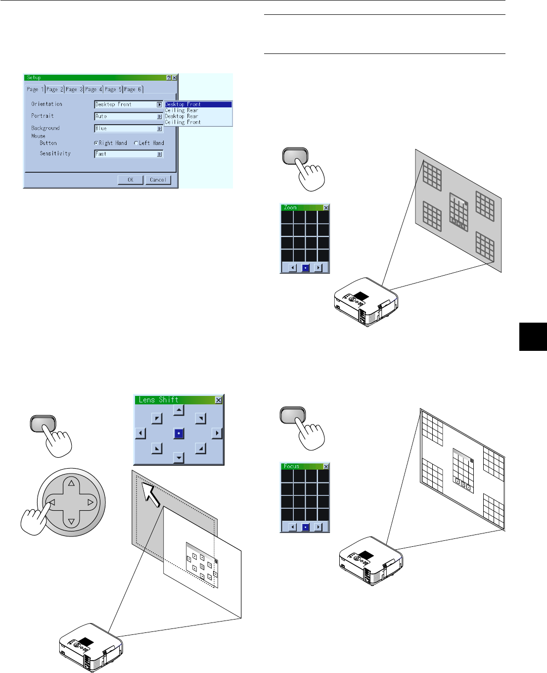
Set up the projector
1.Turn on the projector
2.Select your type of projection:
Desktop front, ceiling rear, desktop rear, and ceiling front.
3.Select the Computer, Video Source or PC Card Viewer
Press a source button on the remote control or the projector cabi-
net to select “Video” (VCR, document camera, or laser disc
player), S-Video”, “RGB” (computer or DVD with component
output), “DVI DIGITAL/ANALOG” or “PC Card Viewer” to dis-
play the image.
Or press the “Menu” button on the remote control or the cabinet
and use the menu to select your video source: “Video”, “S-Video”,
“RGB”, “DVI DIGITAL/ANALOG”, or “PC Card Viewer”.
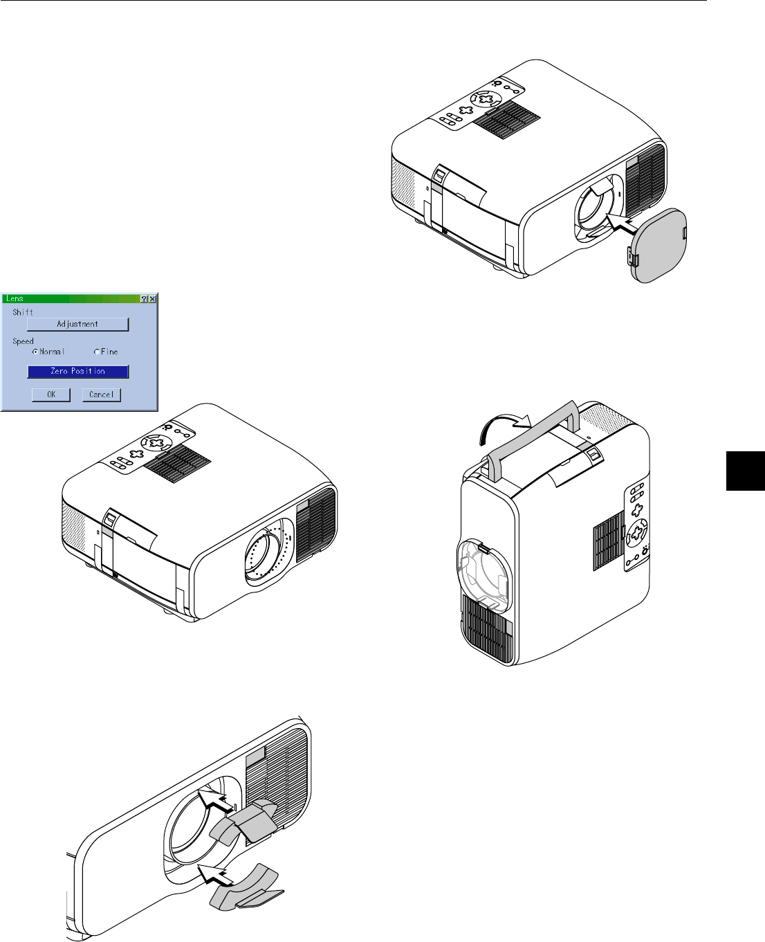
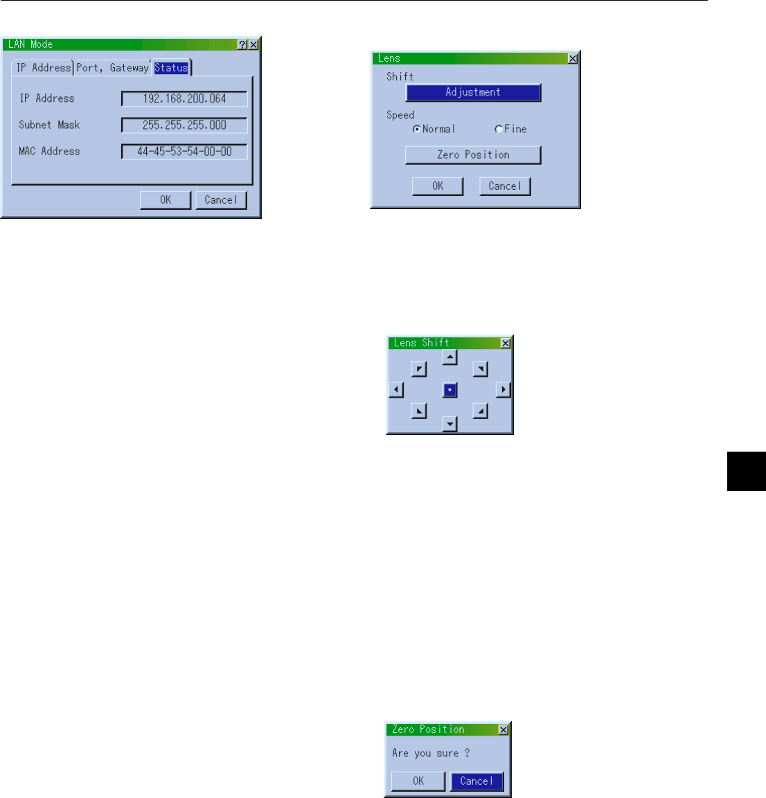
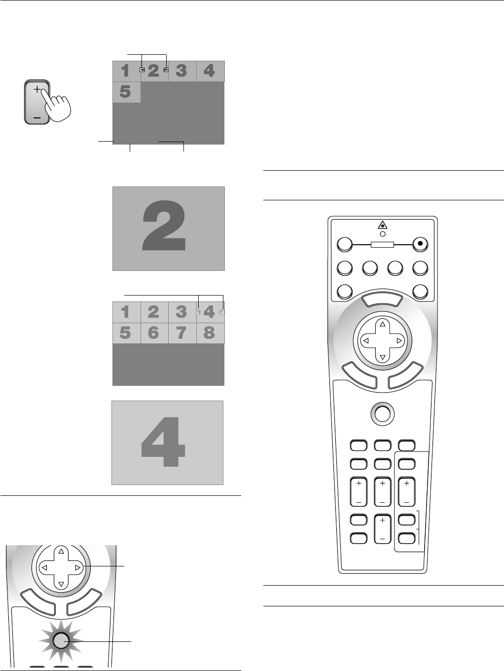
4. Adjust the image position and the image size.
(1) Press the SHIFT button to display the Lens Shift adjustment screen.
Use the Select button on the remote control to move the image horizon-
tally, vertically or diagonally.
To close the Lens Shift adjustment screen, press the CANCEL button.
See page E-20 for “Lens Shift Adjustable Range”.
Projected image position can be shifted by using the LENS SHIFT button
on the cabinet.
Pressing two arrow buttons at the same time can move the lens diago-
nally.
(2) Press the ZOOM button to display the Zoom adjustment screen.
Use the Select
ᮤ
/
ᮣ
button on the remote control to adjust the image
size.
To close the Zoom adjustment screen, press the CANCEL button.
You can also adjust the image size by using the ZOOM + or –button on the
projector cabinet.
(3) Press the FOCUS button to display the Focus adjustment screen.
Use the Select
ᮤ
/
ᮣ
button on the remote control to adjust the focus.
To close the Focus adjustment screen, press the CANCEL button.
You can also adjust the image size by using the FOCUS + or –button on
the projector cabinet.
SELECT
SHIFT
ZOOM
ZOOM
FOCUS
FOCUS
NOTE:In some cases the image may move down a little immediately after a
lens shift adjustment has been made in the downward direction.
(When a lens shift adjustment has been made in the upward direction, this
image movement will not occur)
E – 30
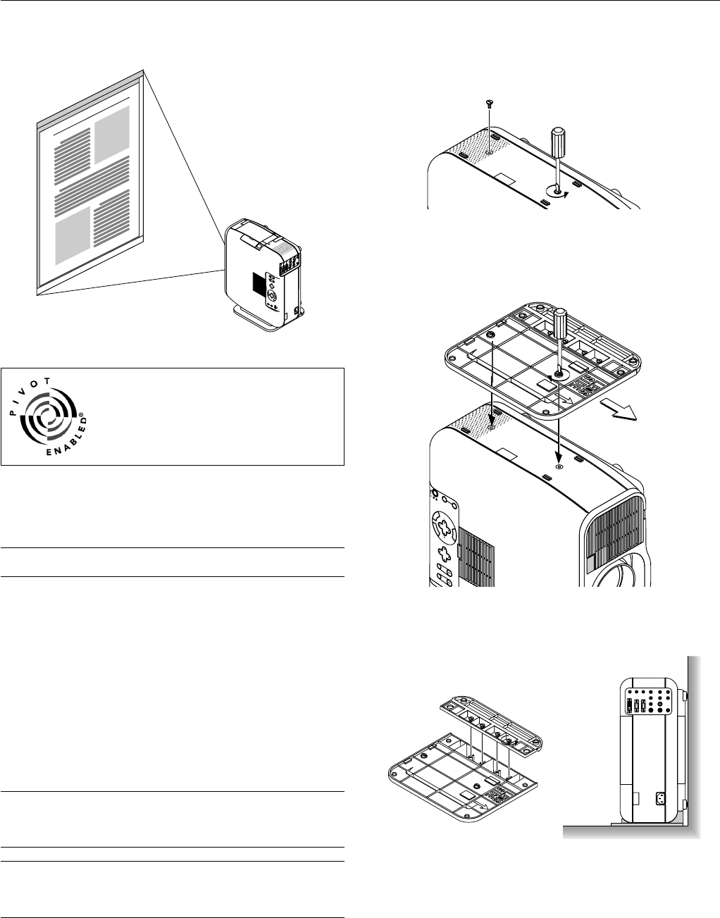
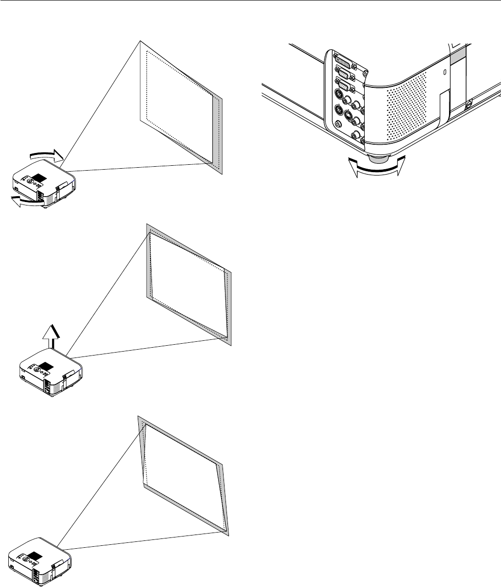
Other adjustments
Rotate the projector to make the
image square.
Use keystone correction for
proper adjustment.
Rotate the four feet to make the
image square to the screen.
Up
Down
Each of the feet height can be changed up to 0.24” (6mm) or at angles
up to 1.8 degrees.
A
U
D
IO
IN
A
U
D
IO
IN
A
U
D
IO
O
U
A
U
D
IO
O
U
T
DVI IN
RGB IN
RGB OUT
PC CONTROL
MOUSE
OUTPUT
REMOTE
CONTROL
INPUT
AUDIO IN
AUDIO IN
R
L/
MONO
VIDEO
S-VIDEO
E – 31
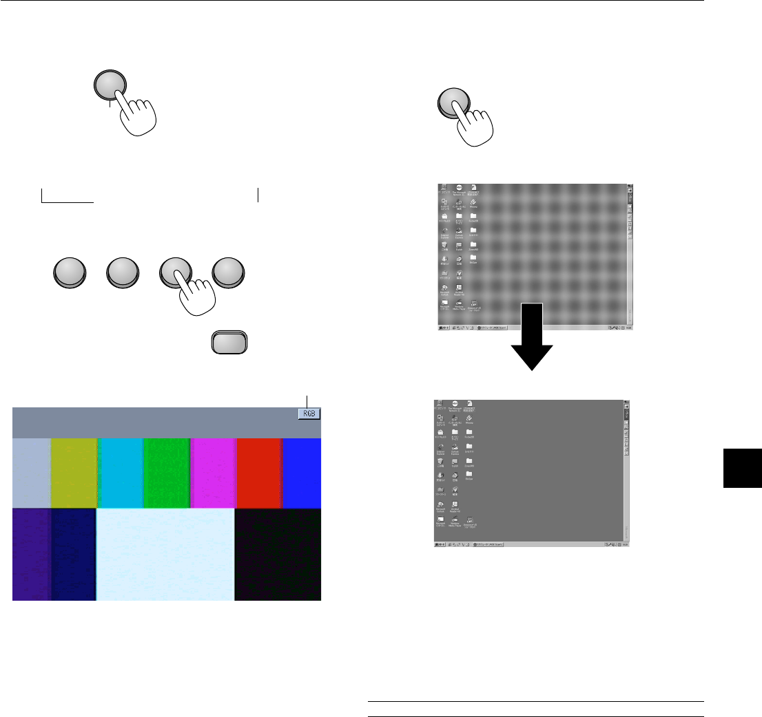
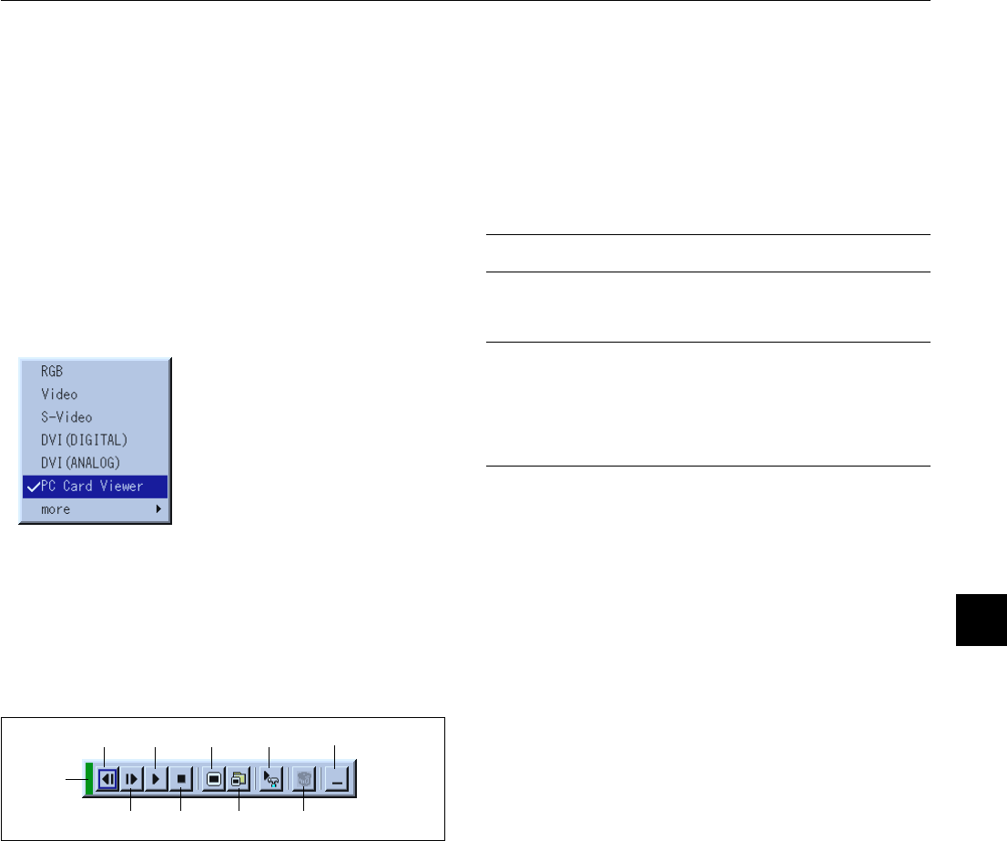
Source display
Each time the Source button is pressed, the input source will change
as follows:
→ RGB → Video → S-Video → DVI (DIGITAL)
PC Card Viewer ← DVI (ANALOG) ←
If no input signal is present, the input will be skipped.
Press the Auto Adjust button to fine-tune the computer image or to
remove any vertical banding that might appear and to reduce video
noise, dot interference or cross talk (this is evident when part of your
image appears to be shimmering). This function adjusts the clock fre-
quencies that eliminate the horizontal banding in the image. This func-
tion also adjusts the clock phase to reduce video noise, dot interfer-
ence or cross talk. (This is evident when part of your image appears to
be shimmering.)
This adjustment may be necessary when you connect your computer
for the first time.
NOTE: The Auto Adjust function does not work for component signal.
Basic Operation
Selecting the computer or video source:
Adjust the Image Using Auto Adjust
The Auto Adjust function automatically optimizes the image in RGB or
DVI (DIGITAL / ANALOG) mode.
[Poor picture]
[Normal picture]
VIDEOS-VIDEORGB1RGB2
PC CARD
AUTO ADJ.
SOURCE
E – 32
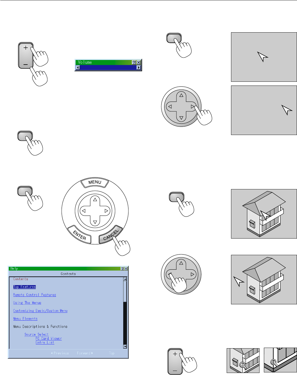
Volume control:
Sound level from the speaker and AUDIO OUTPUT mini jack on the
projector can be adjusted.
Sound is not available when PC Card Viewer is selected.
increase volume
Volume bar
decrease volume
Turning off picture and sound:
Press the Picture Mute button to turn off the image and sound for a
short period of time. Press again to restore the image and sound.
Getting Help about how to operate the projector:
You get the contents about Help.
Display Help
Exit Help
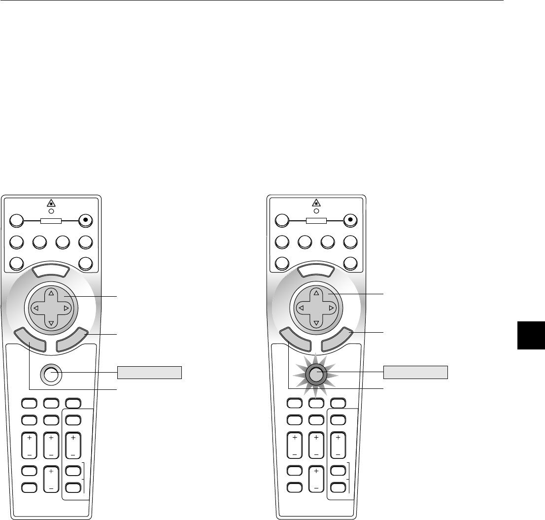
Using Pointer
You can use one of eight pointers to draw your audience's attention to
the portion of a projected image you want.
Press the Pointer button to
display the pointer.
Use the Select button to
move the pointer.
Enlarging and Moving a Picture
You can enlarge the area you want up to 400 percent.
To do so:
1.Press the Pointer button to display the pointer.
2.Move the pointer to the area you want to enlarge.
3.Enlarge the selected area.
When the Magnify (+) button is pressed, the pointer is changed to
a magnifying glass. To move the magnifying glass, use the Select
button.
VOLUME
PIC-MUTE
HELP
SELECT
POINTER
SELECT
POINTER
SELECT
MAGNIFY
E – 33
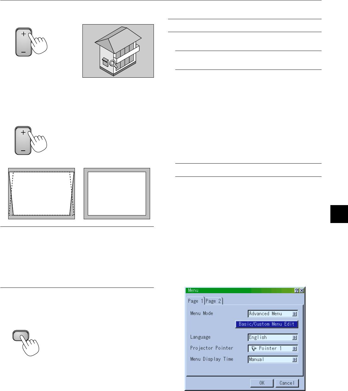
4.Return the image to the original size.
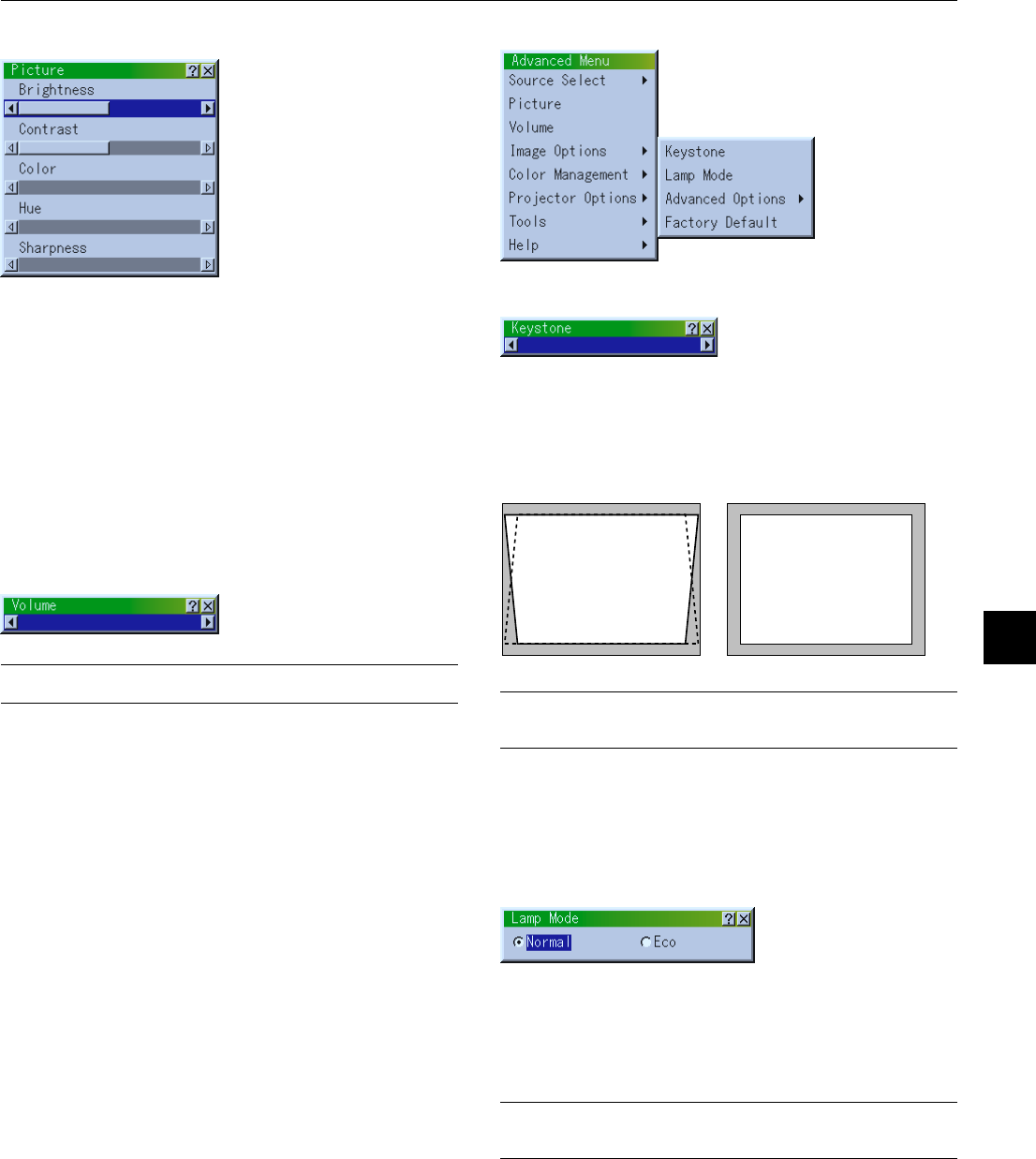
Correcting Keystone distortion
Press (+) or (-) to correct keystone (trapezoidal) distortion to make the
top or bottom of the screen longer or shorter so that the projected
image is rectangular.
NOTE: The maximum keystone angle that can be corrected is 30 degrees up-
ward and 30 degrees downward with the projector placed horizontally on the
ground plane.
Depending on the type of graphics being used, the picture may get blurred or
keystone correction may not be possible when excessive keystone correction
is used.
The idea is, the closer you are to native resolution, the better image you will
see.
In Portrait mode, correct the keystone so that the height at the left and right of
the screen may look the same.
Freezing a picture
Press the Freeze button to freeze a picture. Press again to resume
motion.
Keystone distortionNormal
MAGNIFY
KEYSTONE
FREEZE
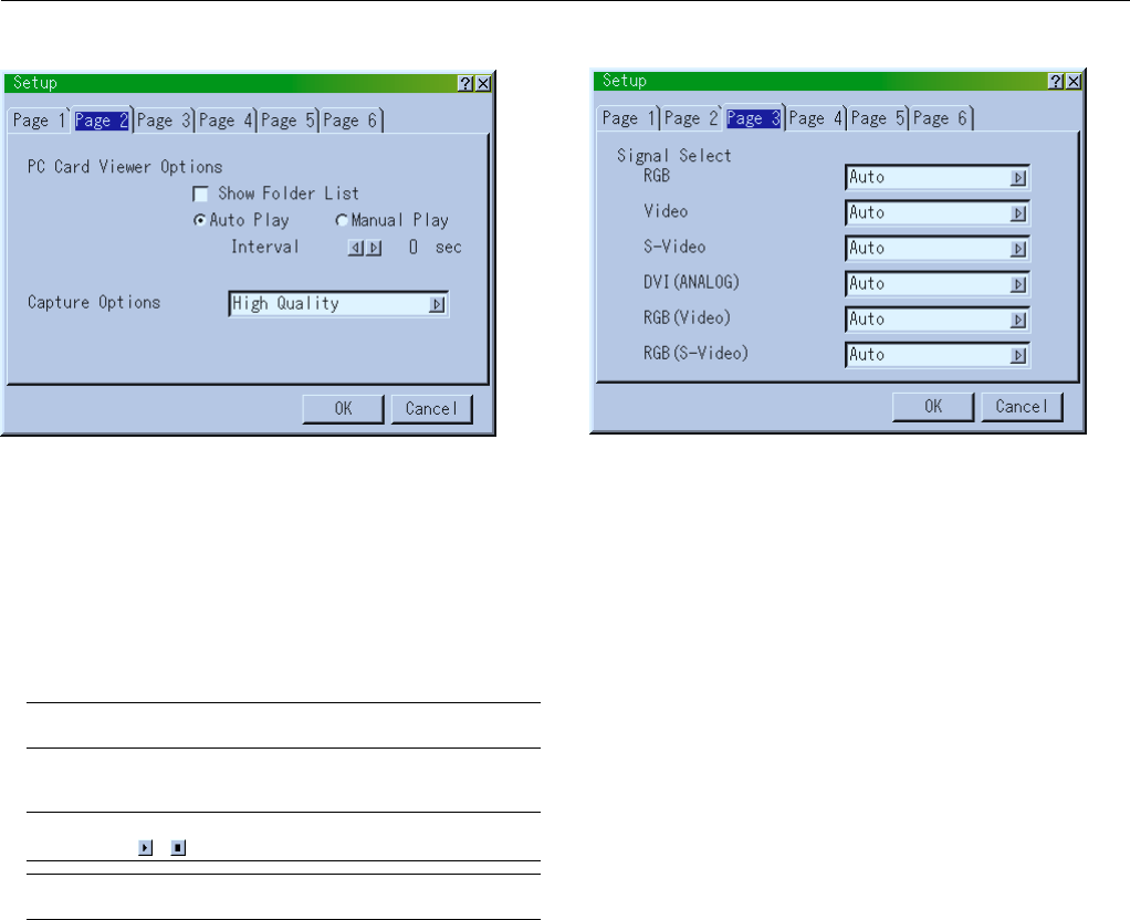
Customizing Basic/Custom Menu
The Basic/Custom menu can be customized to meet your requirements.
Selecting a menu item from the “Basic/Custom Menu Edit” list, allows
you to custom tailor the menu items to your needs.
1.Select “Basic/Custom Menu Edit” to display the “Basic/Custom
Menu Edit” screen.
Using the Menus
NOTE: The on-screen menu may not be displayed correctly while interlaced
motion video image is projected.
1.Press the “Menu” button on the remote control or projector cabi-
net to display the Main Menu.
NOTE: When using a USB mouse, click the mouse button to display the
main menu. For other operations, do the same way as you use your PC
mouse.
2.Press the ▲▼ buttons on the remote control or the projector cabi-
net to highlight the menu for the item you want to adjust or set.
3.Press the
ᮣ
button or the “Enter” button on the projector cabinet
or the remote control to select a submenu or item.
4.Adjust the level or turn the selected item on or off by using “Se-
lect”
ᮤ
or
ᮣ
buttons on the cabinet or the remote control. The on-
screen slide bar will show you the amount of increase or decrease.
5.Changes are stored until you adjust it again.
ENTER.........Stores the setting or adjustments.
CANCEL..........
Return to the previous screen without storing settings or ad-
justments.
NOTE: You can close the main and sub menus simultaneously by pressing
the PJ button to cancel the Projector mode.
6.Repeat steps 2-5 to adjust an additional item, or press “Cancel”
on the projector cabinet or the remote control to quit the menu
display.
E – 34
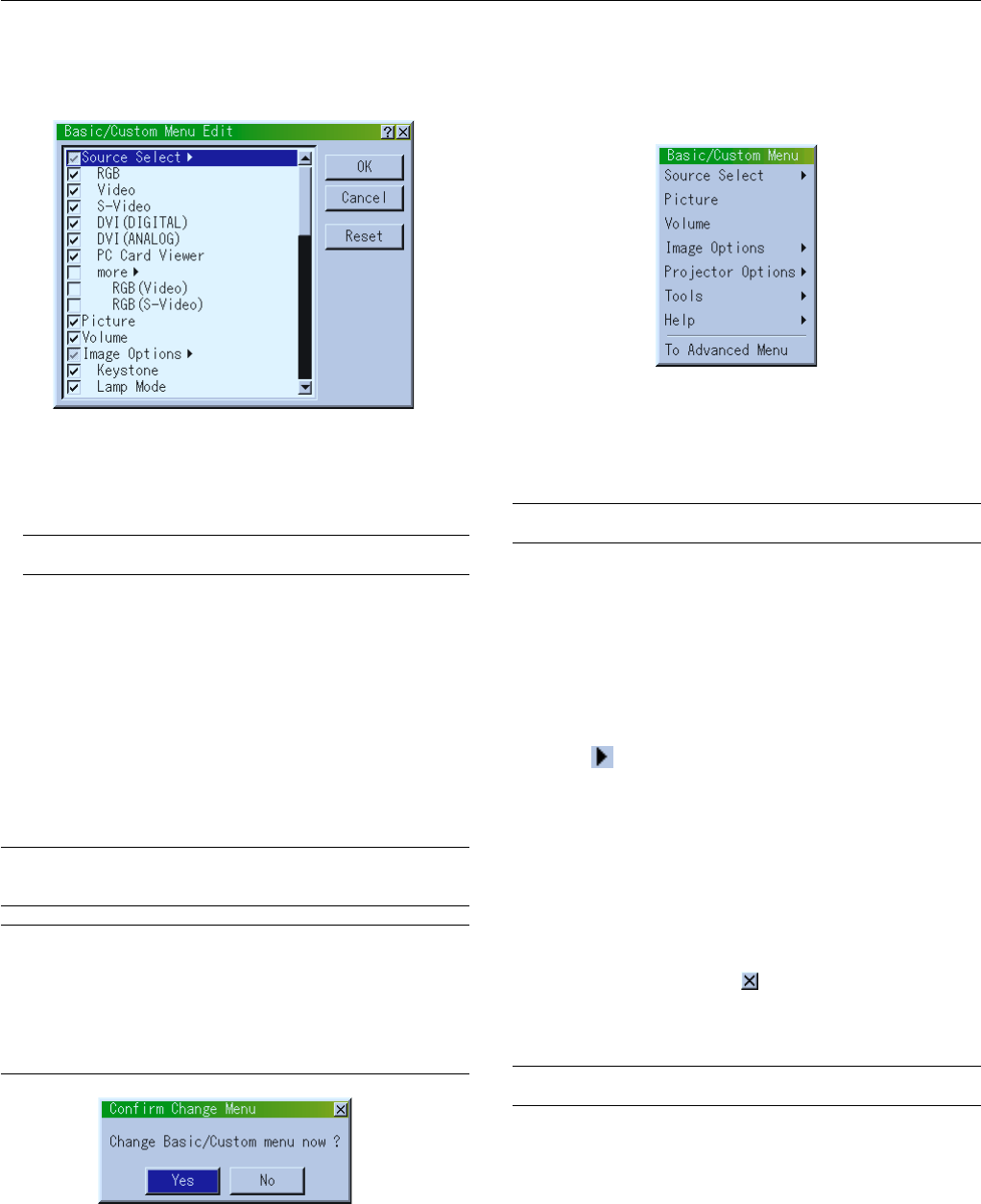
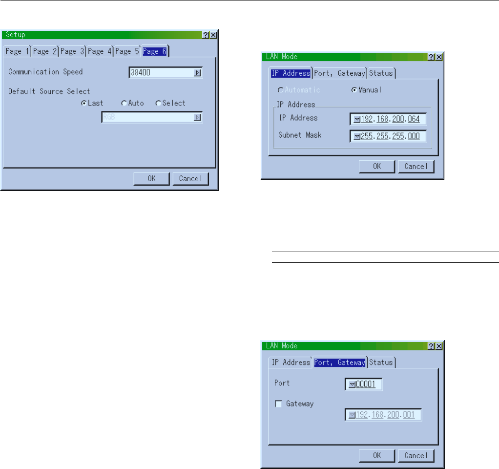
3.In order for the changes to take effect, use the
ᮤ
or
ᮣ
button on
the remote control or the projector cabinet to highlight “OK”,
then press the Enter button. To cancel the changes, use the ▲ or
▼ buttons to highlight “Cancel” and press the “Enter” button.
To return to the factory default, select “Reset” then press the “En-
ter” button.
The default Basic/Custom Menu items are:
Source Select [RGB, Video, S-Video, DVI (DIGITAL/ANALOG) and
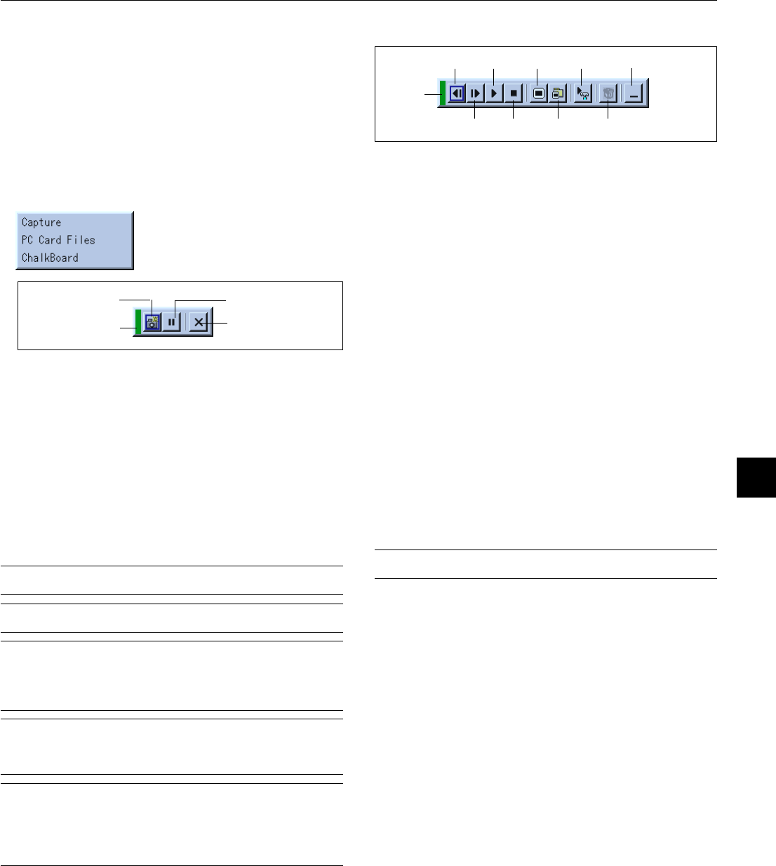
PC Card Viewer], Picture, Volume, Image Options (Keystone, Lamp
Mode and Factory Default), Projector Options (Menu), Tools (Cap-
ture, PC Card Files and ChalkBoard) and Help (Contents and Infor-
mation)
NOTE: Once you have selected OK on the Basic/Custom Menu Edit screen, you
cannot cancel the changes on the Menu screen. However, you can re-edit the
menu items over again as described in the steps above.
NOTE: If the “Advanced Menu” item has been selected on the Menu mode, you
get the “Confirmation Change Menu” upon completion of “Basic/Custom Menu”
editing. In this case, selecting “Yes” then “Enter” will close all the menus and
apply the changes from the Advanced menu to the Basic/Custom Menu. If you
select “No” then “Enter” functions, then all menu items will return to the Ad-
vanced menu, but your changes will still be available within the “Basic/Custom
Menu” selection. To display the previously tailored Basic/Custom Menu, select
“Basic/Custom Menu” from the “Menu Mode”.
An item “To Advanced Menu” will be added to the bottom of the Basic/
Custom Menu.
Selecting this item and pressing the “Enter” button will display the “Ad-
vanced Menu” features.
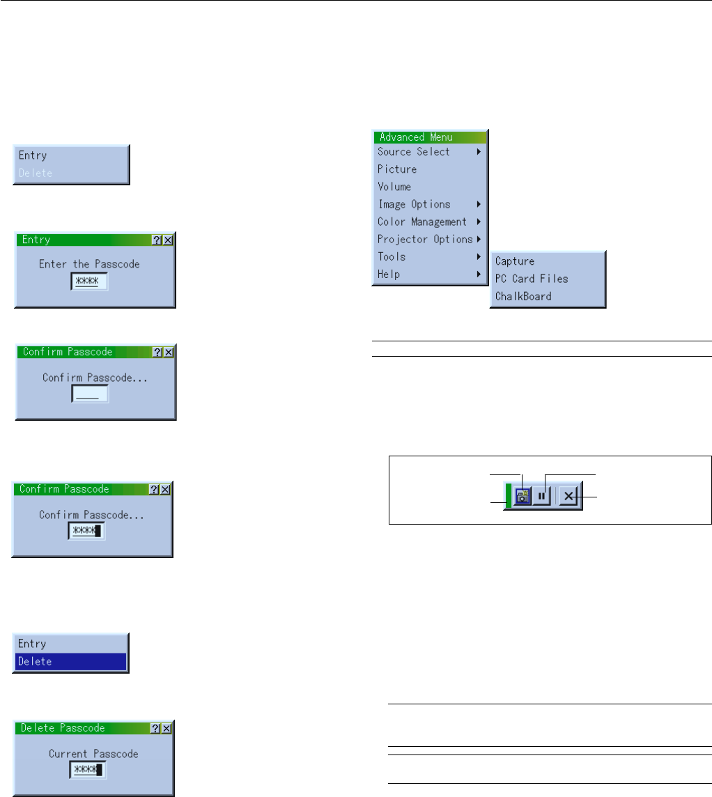
When a passcode is set for your projector, the Passcode input screen
will be displayed, See page E-48 for more information.
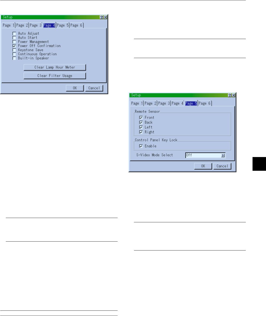
2.Use the ▲ or ▼ button to highlight your selection and press the
Enter button to place a check mark next to an option. This action
enables that feature.
Press the Enter button again to clear the check box.
If you select an item with a solid triangle
ᮣ
and press the Enter
button on the remote control or the projector cabinet, you can
enable all the items within that submenu.
Also you can turn on an item within the submenu without placing
a check mark on the main menu item.
NOTE: Up to 12 main menu items (within Basic/Custom Menu Edit, not
including submenu items) can be selected.
Using a USB Mouse
Using a USB mouse gives you a smooth operation. A commercially
available USB mouse is required.
NOTE: There may be some brands of USB mouse that the projector does not
support.
Operate the Menus using the USB mouse:
Mouse Cursor:
When connecting a USB mouse to the projector, you get a mouse
cursor on the screen.
Unless you use your USB mouse within 10 seconds, the mouse
cursor disappears.
Menu Display:
Clicking with a mouse button displays the main menu.
Clicking displays the pull-down menu.
To close the menu, click anywhere in the background.
Adjusting and Setting Display:
You can select a menu item and click with a mouse button to make
adjustments and setting.
Examples:
Click (or press and hold) the mouse button
ᮤ
or
ᮣ
to adjust the
brightness.
Or click and drag the mouse button on the slide bar horizontally to
adjust it.
To save the adjustments, click . The display is closed.
If you click anywhere in the background while displaying adjust-
ment and setting menu or dialog box, you will get the main menu at
the clicking point.
NOTE: The MOUSE OUTPUT port on the projector is not compatible with the
USB mouse.
E – 35
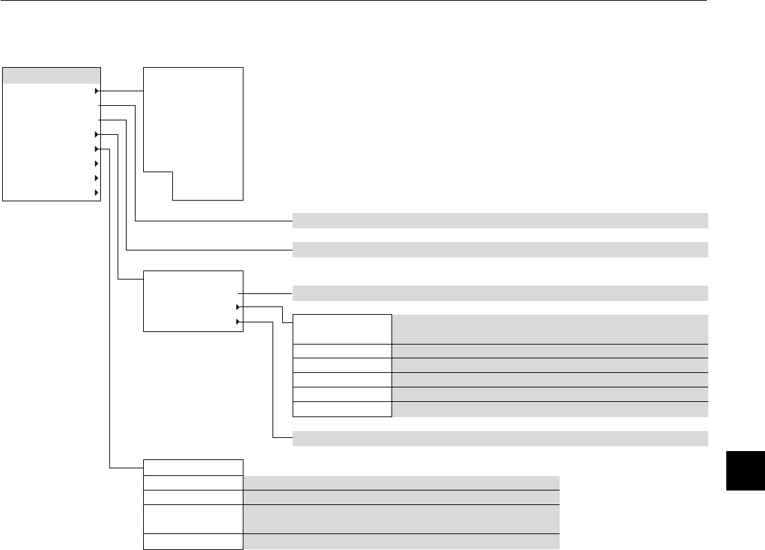
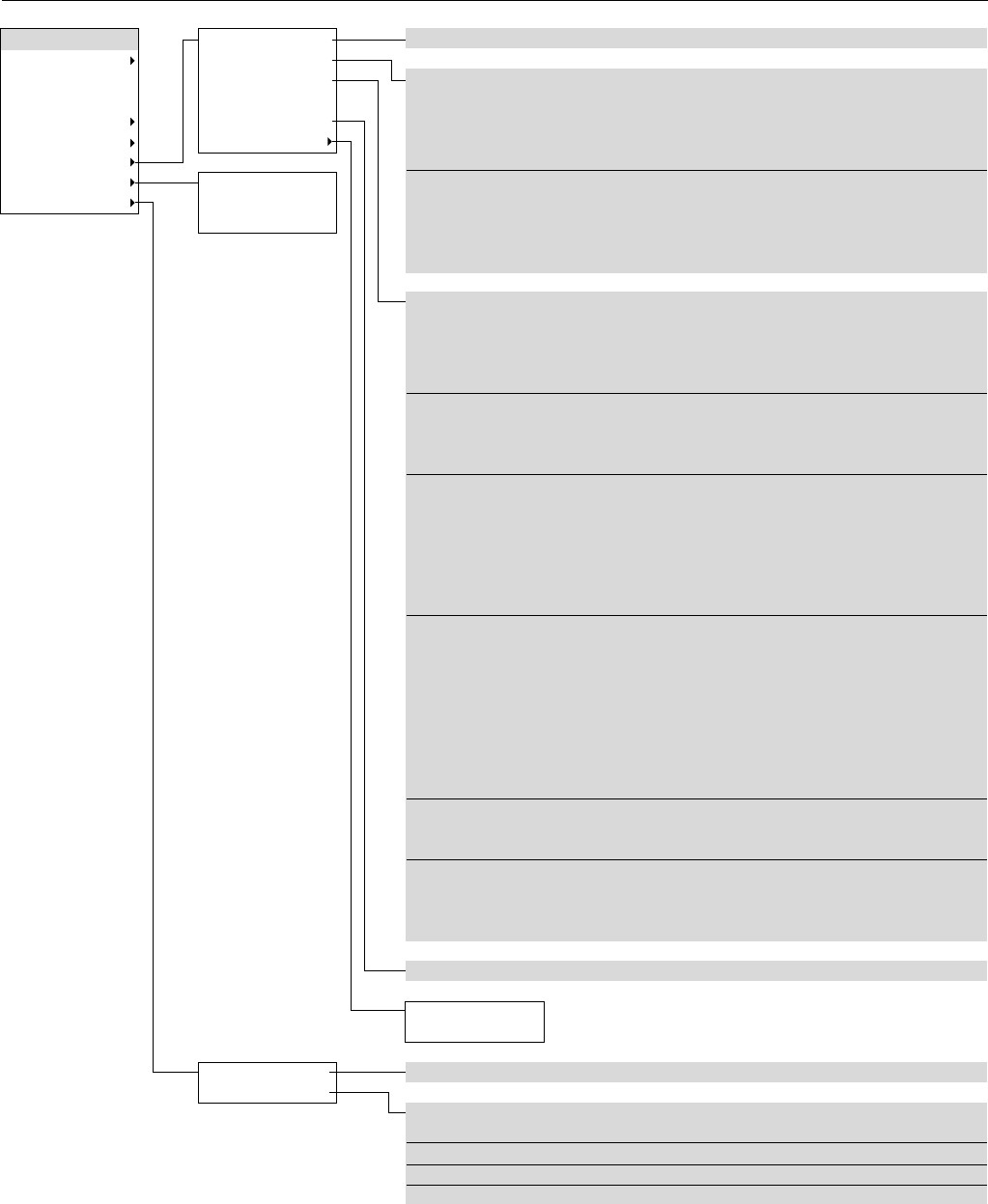
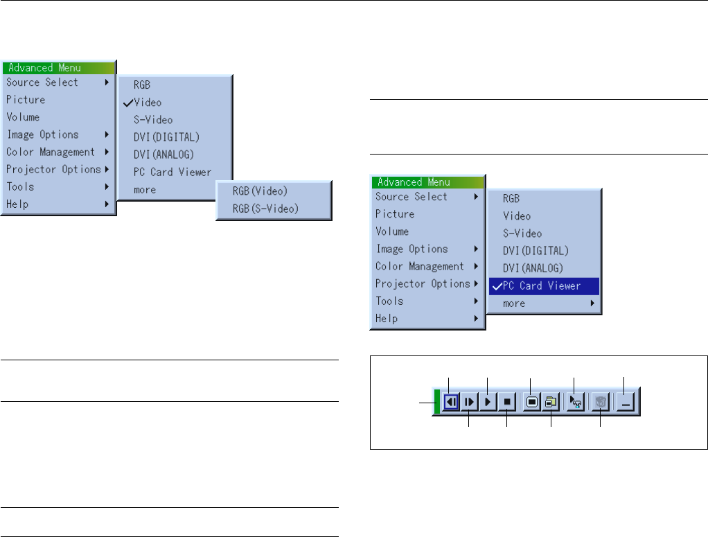
Menu Tree
Advanced Menu
Source Select
Picture
Volume
Image Options
Color Management
Projector Options
Tools
Help
RGB
Video
S-Video
DVI (DIGITAL)
DVI (ANALOG)
PC Card Viewer
more
RGB (Video)
RGB (S-Video)
Brightness / Contrast / Color / Hue / Sharpness
Volume
Normal / Eco
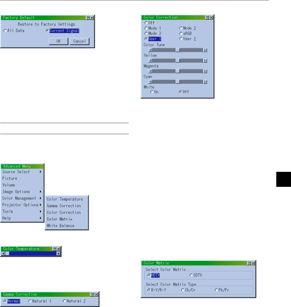
All Data / Current Signal
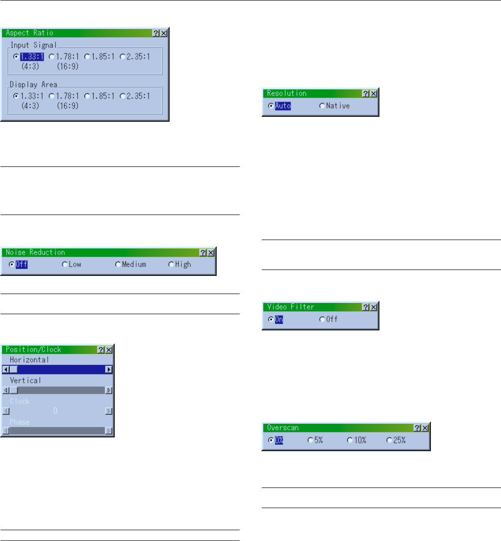
Aspect Ratio
Noise Reduction
Position / Clock
Resolution
Video Filter
Overscan
Input Signal (1.33:1 / 1.78:1 / 1.85:1 / 2.35:1)
Display Area (1.33:1 / 1.78:1 / 1.85:1 / 2.35:1)
Off / Low / Medium / High
Horizontal / Vertical / Clock / Phase
Auto / Native
On / Off
0% / 5% / 10% / 25%
Normal / Natural 1 / Natural 2
Off / Mode 1 / Mode 2 / Mode 3 / sRGB / User 1 / User 2
Select Color Matrix HDTV / SDTV
Select Color Matrix Type B-Y / R-Y, Cb / Cr, Pb / Pr
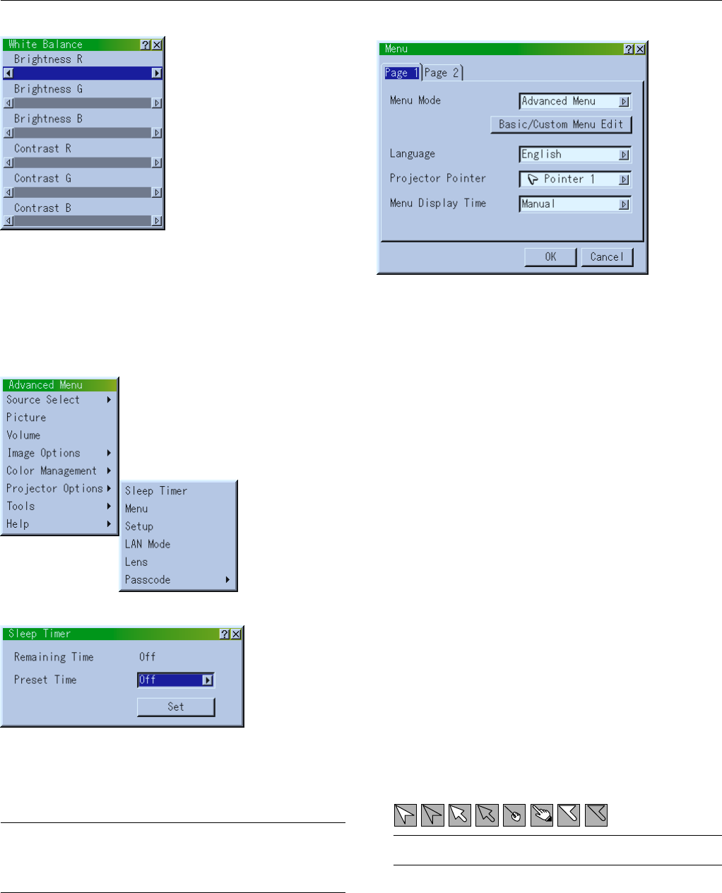
Brightness R/G/B, Contrast R/G/B
Keystone
Lamp Mode
Advanced Options
Factory Default
Color Temperature
Gamma Correction
Color Correction
Color Matrix
White Balance
E – 36
Advanced Menu
Source Select
Picture
Volume
Image Options
Color Management
Projector Options
Tools
Help
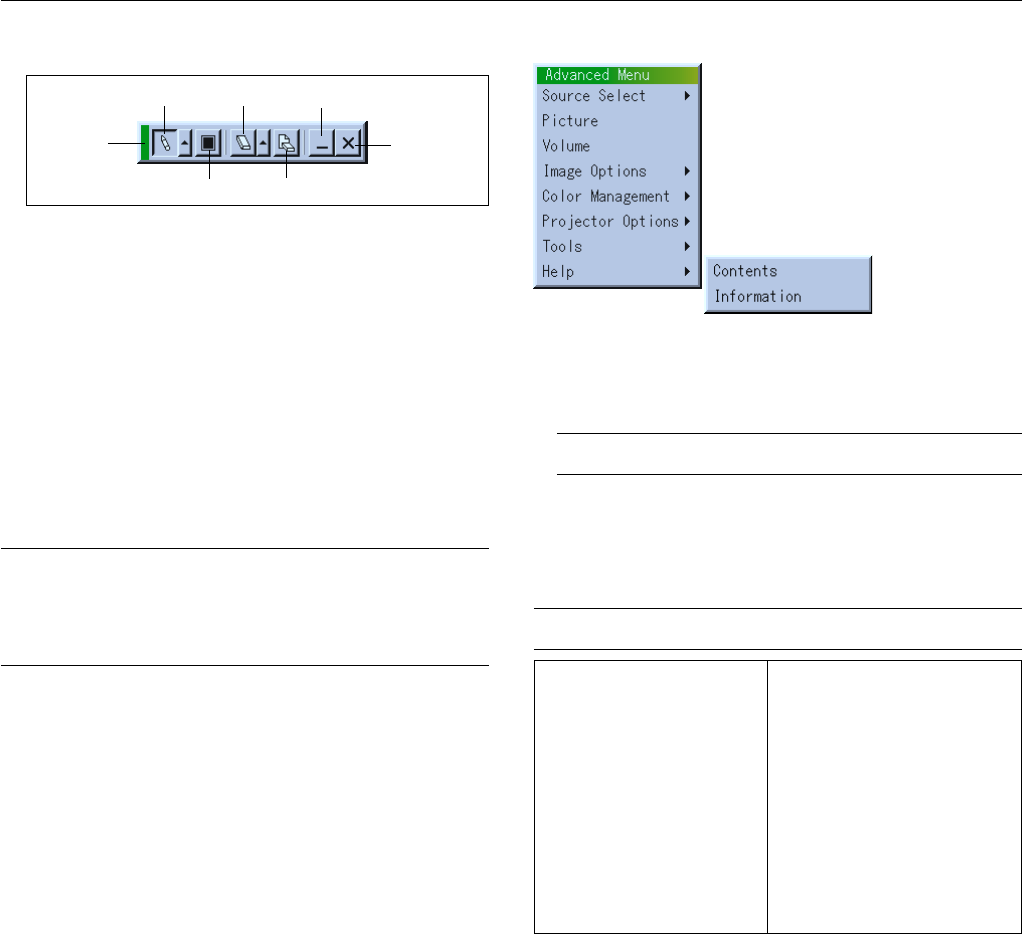
Contents
Information
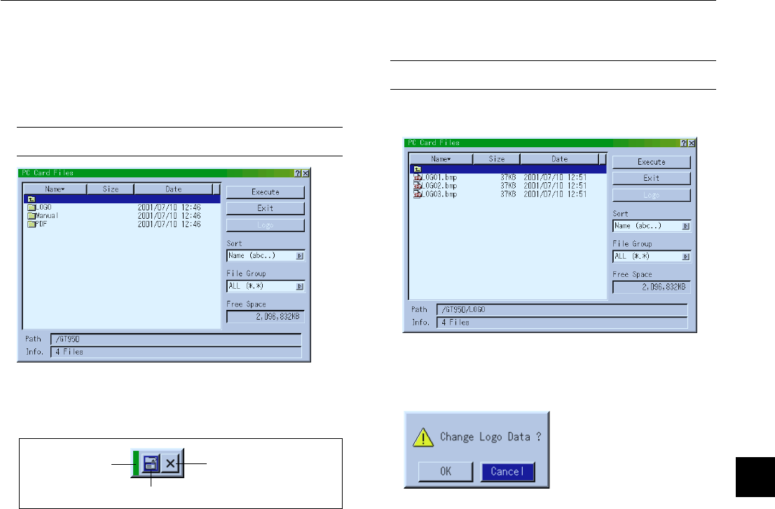
Capture
PC Card Files
ChalkBoard
Shift (Adjustment), Speed (Normal / Fine), Zero Position
Contents
Page 1
Page 2
Page 3
Page 4
Source Name / Input Terminal / Entry No. / Horizontal Frequency /
Vertical Frequency / Sync Polarity
Signal Type / Video Type / Sync Type / Interlace
Remaining Lamp Time / Lamp Hour Meter / Filter Usage / Projector Usage
Version (BIOS / Firmware / Data / SUB-CPU)
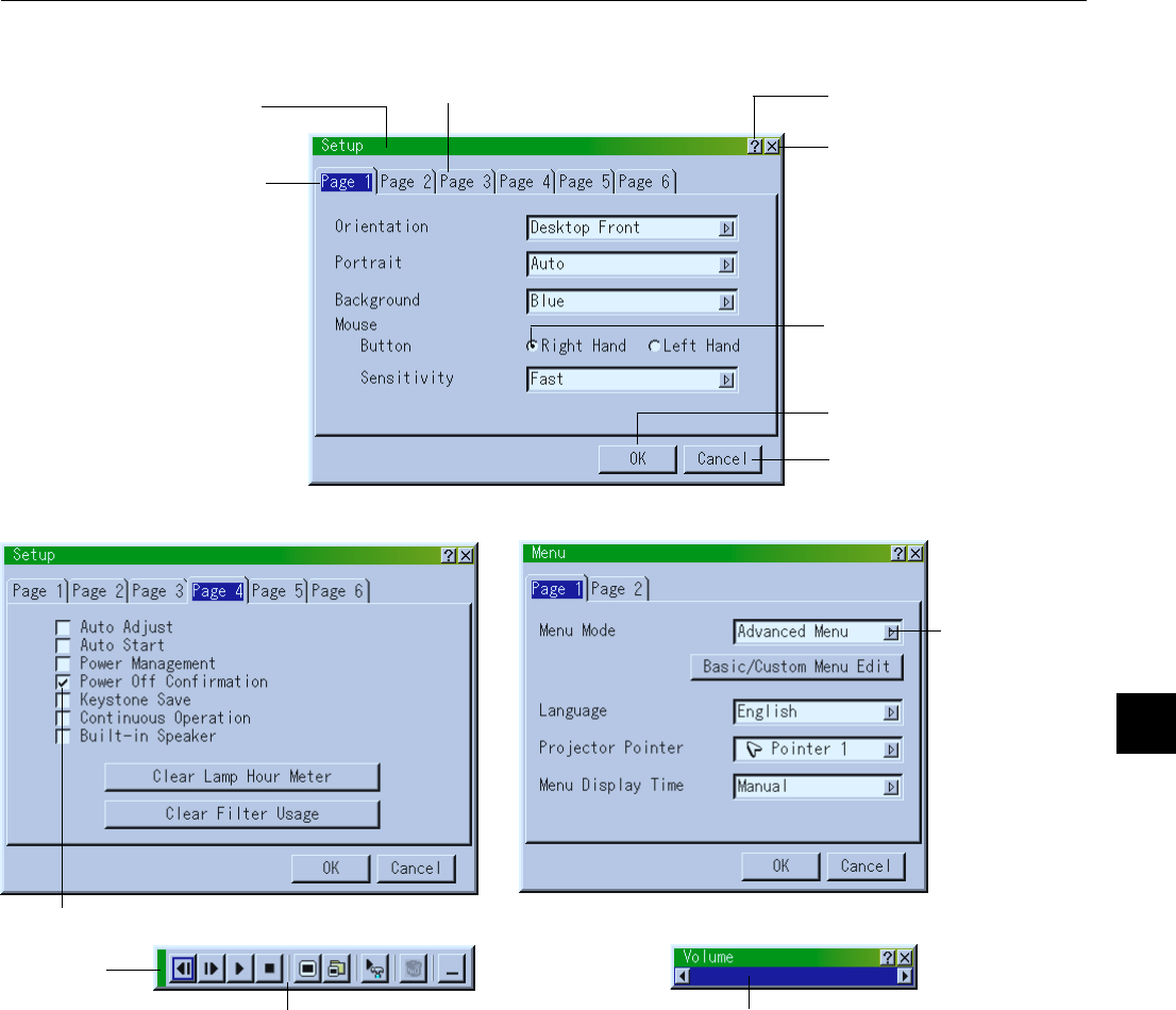
Page 1
Page 2
Menu Mode (Advanced Menu, Basic/Custom Menu)
Basic/Custom Menu Edit
Language (English / German / French / Italian / Spanish / Swedish / Japanese)
Projector Pointer (Pointer 1-8)
Menu Display Time (Manual / Auto 5 sec / Auto 15 sec / Auto 45 sec)
Libble takes abuse of its services very seriously. We're committed to dealing with such abuse according to the laws in your country of residence. When you submit a report, we'll investigate it and take the appropriate action. We'll get back to you only if we require additional details or have more information to share.
Product:
Forumrules
To achieve meaningful questions, we apply the following rules:
First, read the manual;
Check if your question has been asked previously;
Try to ask your question as clearly as possible;
Did you already try to solve the problem? Please mention this;
Is your problem solved by a visitor then let him/her know in this forum;
To give a response to a question or answer, do not use this form but click on the button 'reply to this question';
Your question will be posted here and emailed to our subscribers. Therefore, avoid filling in personal details.
Register
Register getting emails for Nec GT950 at:
new questions and answers
new manuals
You will receive an email to register for one or both of the options.
Get your user manual by e-mail
Enter your email address to receive the manual of Nec GT950 in the language / languages: English as an attachment in your email.
The manual is 3,27 mb in size.
You will receive the manual in your email within minutes. If you have not received an email, then probably have entered the wrong email address or your mailbox is too full. In addition, it may be that your ISP may have a maximum size for emails to receive.
If you have not received an email with the manual within fifteen minutes, it may be that you have a entered a wrong email address or that your ISP has set a maximum size to receive email that is smaller than the size of the manual.
The email address you have provided is not correct.
Please check the email address and correct it.
Your question is posted on this page
Would you like to receive an email when new answers and questions are posted? Please enter your email address.