Application description – air quality sensor & control
General Information
The device fits for the particular use of the following tasks: monitoring of the air quality in building systems technology (schools, offices, hotels, conference venue etc.), data
transfer and regulation via bus system. The device is intended for use in accordance with the defined technical data. Operatethe device exclusively in a dry room! The device is
not qualified for security relevant tasks such as emergency doors, fire protection equipment, fermenting cellars etc.
The air quality sensor GS 3x.10knx can provide the following data and control for the KNX bus:
Please consider that handling and installation of the device is explained in the instruction manual enclosed to the product!
Please take into account the resolution of the 2 Bytes data type (see KNX Specification)!
Relative humidity: Value output
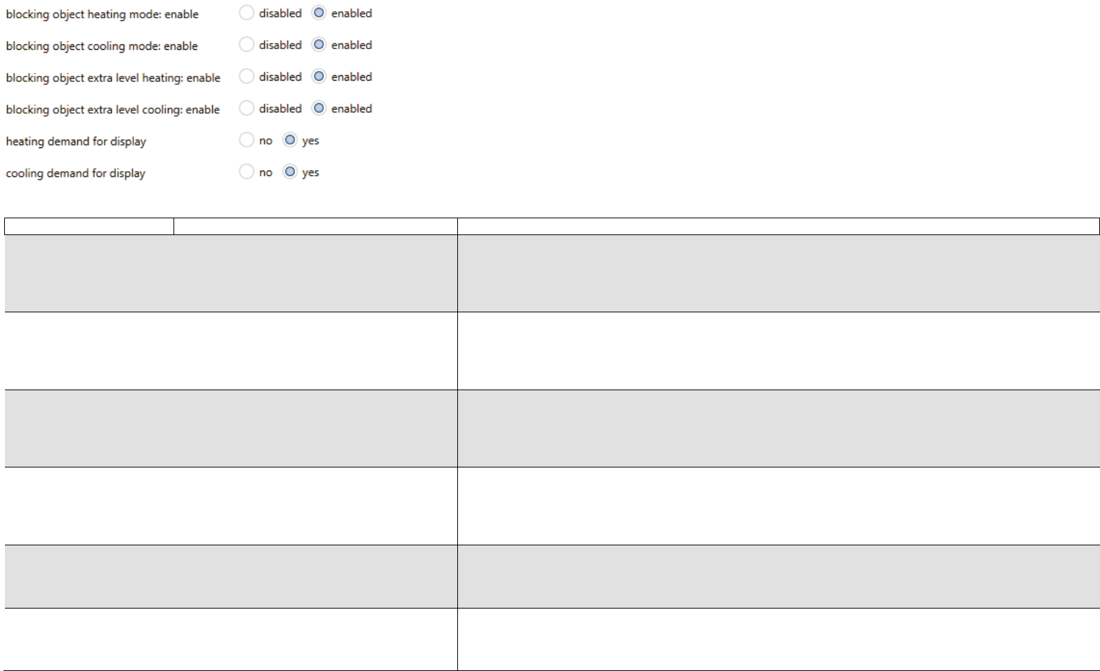
Control (step and PI control)
Temperature:Value output
Control heating / cooling (2-point and PI control)
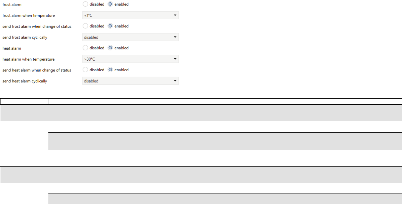
Alarms
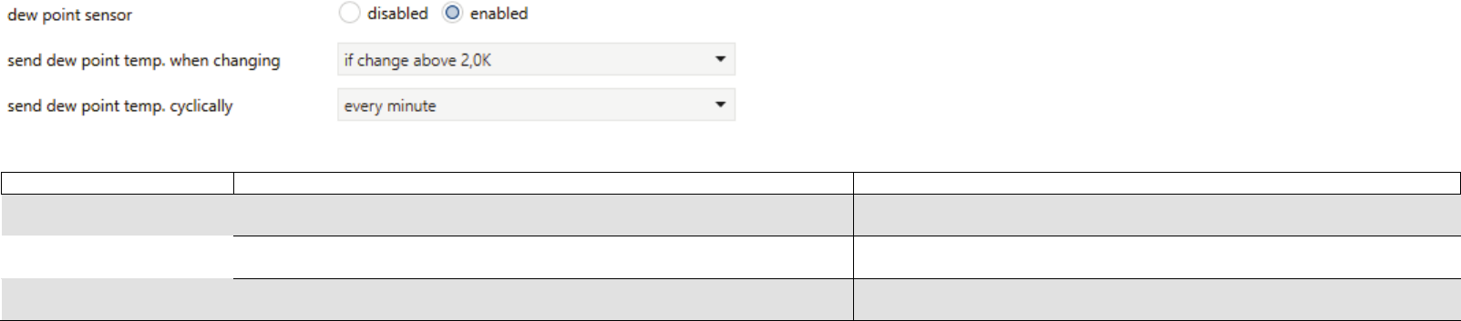
Dew point:Value output
Alarm
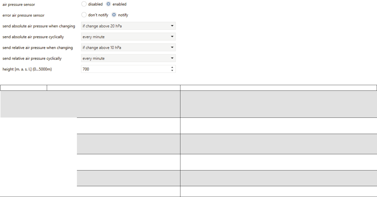
Air pressure:Value output
GS 30.10 knx
GS 31.10 knx
TECHNICAL MANUAL GS 3x.10KNX – ENGLISH
2
Table of contents
General Information......................................................................................................................................................................................................................................................................................... 1
Technische Daten.....................................................................................................................................................................................................................................Fehler! Textmarke nicht definiert.
Communication objects................................................................................................................................................................................................................................................................................... 5
Communication flags.....................................................................................................................................................................................................................................................................................17
3.1Switching commands and priority relative humidity control – Threshold 1 / 2 / 3................................................................................................................................................................................22
3.2PI control for relative humidity.............................................................................................................................................................................................................................................................23
6.1Temperature control – heating and cooling.........................................................................................................................................................................................................................................26
6.2Temperature control – General...........................................................................................................................................................................................................................................................27
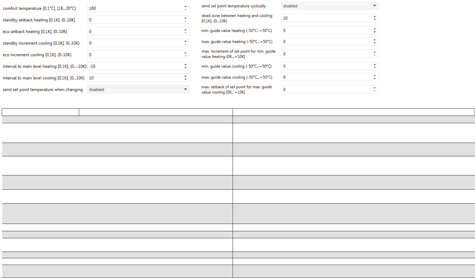
6.3Temperature control – Set points........................................................................................................................................................................................................................................................28
6.4Temperature control – Main level and extra level heating / cooling....................................................................................................................................................................................................29
7.Dew point Temperature......................................................................................................................................................................................................................................................................30
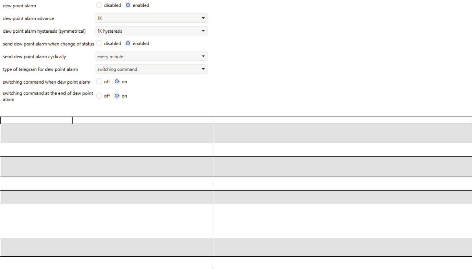
8.Dew point Alarm.................................................................................................................................................................................................................................................................................31
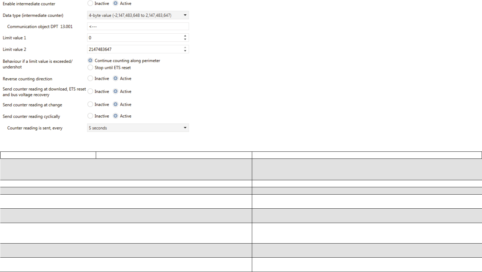
11.2.1.8.1.Intermediate counter (with function pulse counter)................................................................................................................................................................................................................46
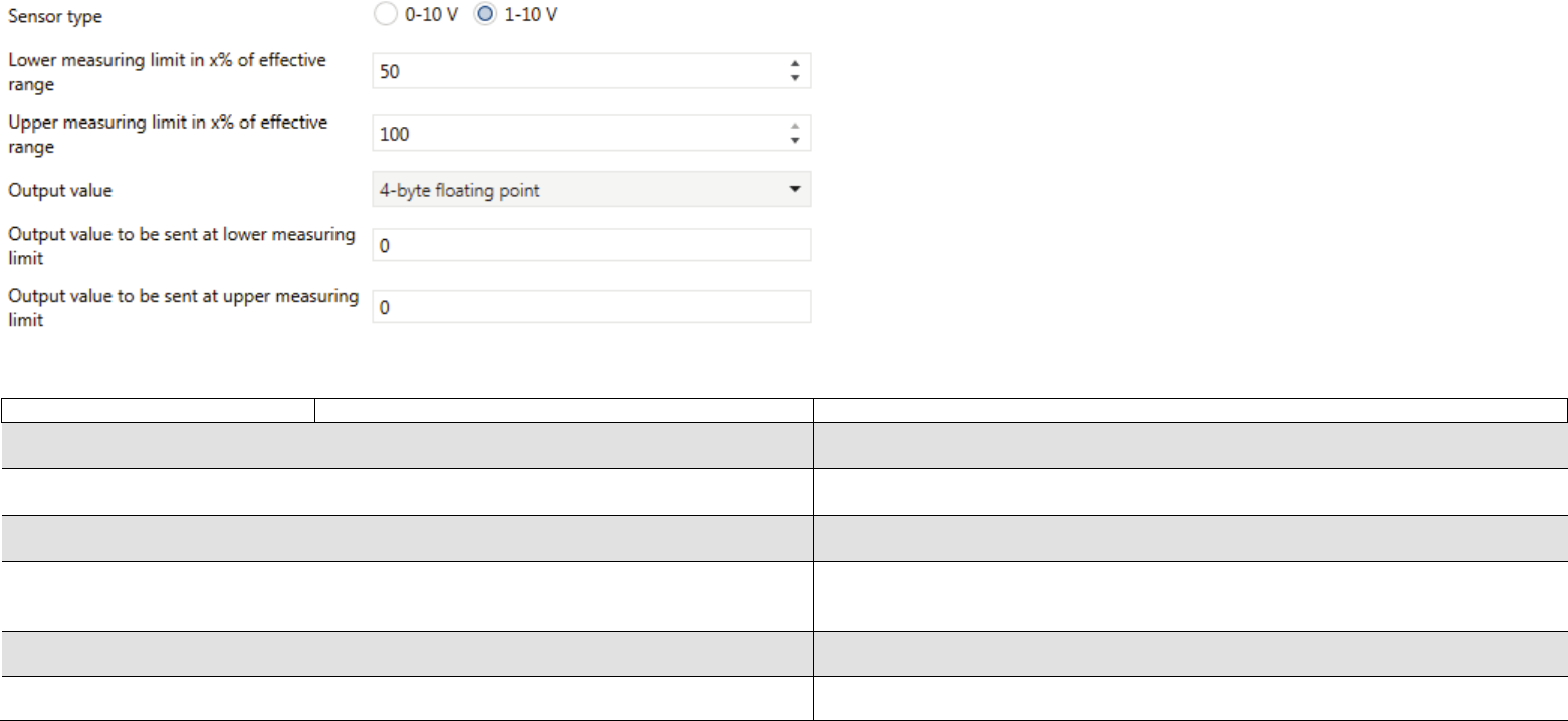
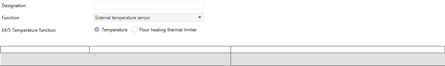
11.2.2Function analogue input (Only available at input E1).....................................................................................................................................................................................................................47
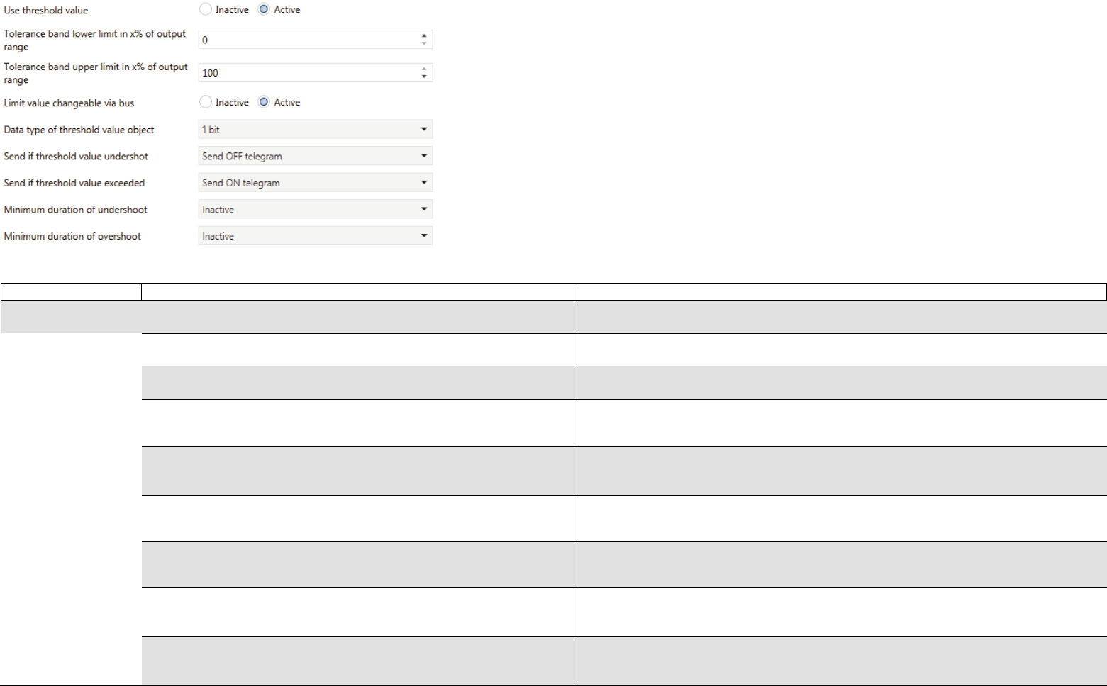
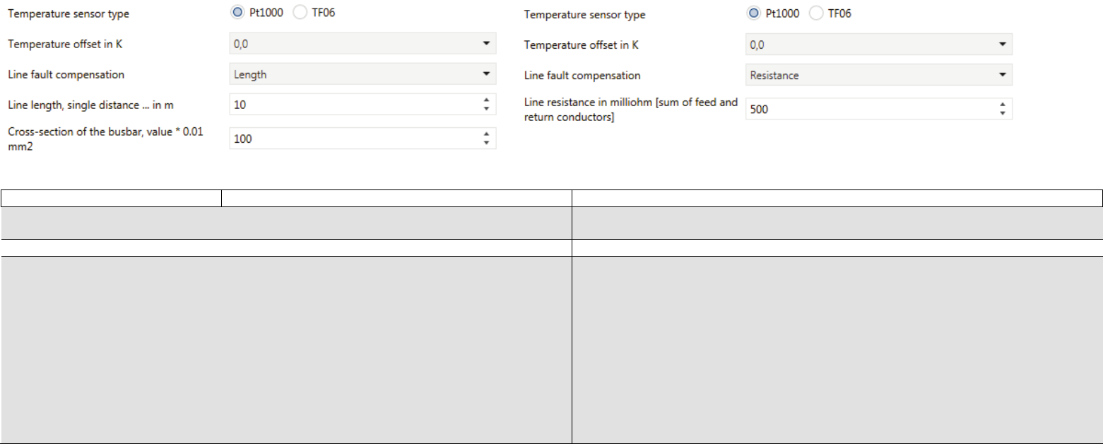
11.2.3.4E4/5 Threshold value 1 / 2 (only if E4 General temperature function = Temperature)...........................................................................................................................................................54
11.2.3.5E4/5 Output threshold value 1 / 2 (only if E4 general temperature function = Temperature).................................................................................................................................................55
11.2.3.6E4/5 Threshold values (only if E4 general temperature function = Floor heating thermal limiter)..........................................................................................................................................55
TECHNICAL MANUAL GS 3x.10KNX – ENGLISH
3
Application program
Manufacturer: Hugo Müller GmbH & Co KG, Sturmbühlstraße 145-149, D-78054 VS-Schwenningen
Programname:GS 3x.10 knx
Installation:Add the device to your devicelist and open a new project. You can download the ETS database on our webpage:
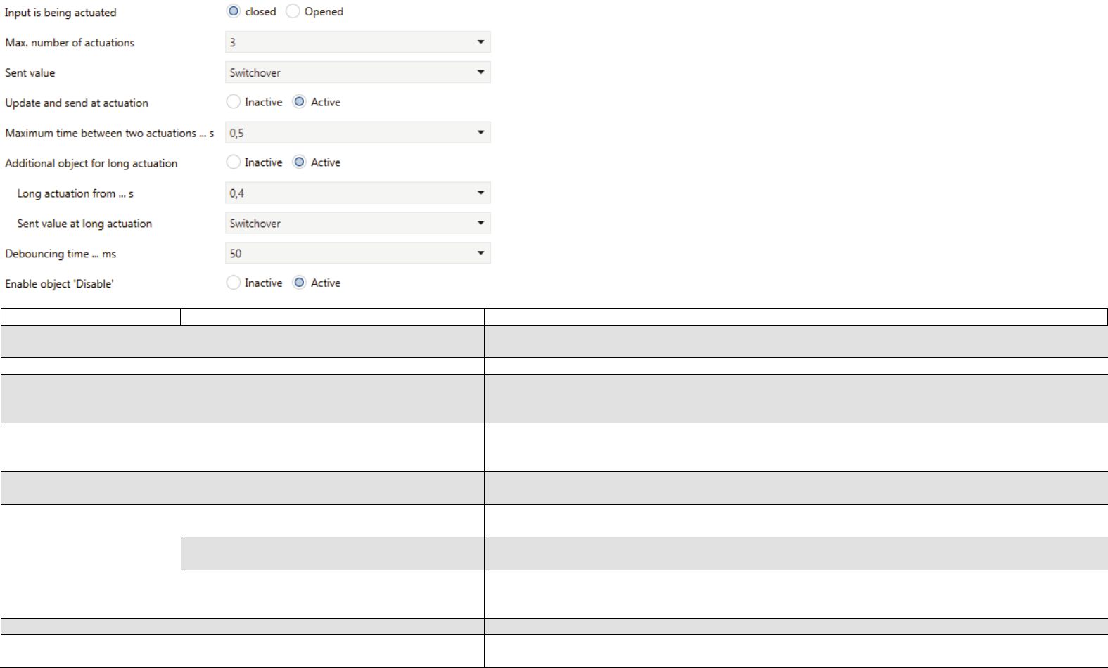
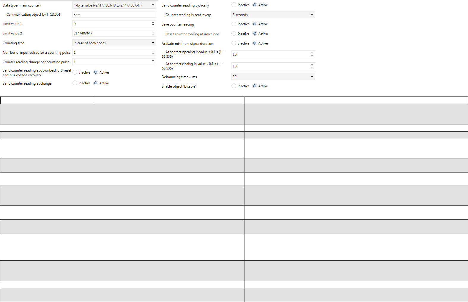
162E5 ZZ: Counter reading 4-Byte-valueoutputC - - T - 4 Bytes4-Byte signed value, counter pulses
163E5 Start event 0/1inputC - W - - 1 Bitswitching
163E5 End position topinputC - W - - 1 BitBoolean
163E5 Scene storage displayoutputC - - T - 1 Bitenable
163E5 switchinglevel 3 outputC - - T - 1 Bitswitching
163E5 switching3 actuationoutputC - - T - 1 Bitswitching
163E5 HZ: Counter readingrequestinputC - W - - 1 Bitswitching
164E5 End position bottominputC - W - - 1 BitBoolean
164E5 switchinglevel 4 outputC - - T - 1 Bitswitching
164E5 switching4 actuationoutputC - - T - 1 Bitswitching
164E5 HZ: Limit value exceededoutputC - - T - 1 BitBoolean
165E5 Store sceneinputC - W - - 1 Bitenable
165E5 Enable saveinputC - W - - 1 Bitenable
165E5 switchinglevel 5 outputC - - T - 1 Bitswitching
165
E5 Switching long actuation
output
C
-
-
T
-
1 Bit
switching
166E5 Levelup/down switchinginputC - W - - 1 Bitswitching
166E5 ZZ: Limit value exceededoutputC - - T - 1 BitBoolean
167
E5 Number actuations
input
C
-
W
-
-
1 Byte
counter pulses (0...255)
167E5 ZZ: Counter readingrequestinputC - W - - 1 Bitswitching
168E5 ZZ: Reverse directioninputC - W - - 1 BitBoolean
169E5 ZZ: resetinputC - W - - 1 BitBoolean
170E5 ZZ: StopinputC - W - - 1 BitBoolean
179E5 DisableinputC - W - - 1 Bitenable
Communication flags
Flag
Name
Meaning
C
Communication
Object can communicate
R
Read
Object status can be requested (ETS, display etc.)
TECHNICAL MANUAL GS 3x.10KNX – ENGLISH
18
W
Write
Object can receive information
T
Transmit
Object can send information
U
Update
Object can request a value from another bus participant. The answer is interpreted as write command and updates the value of the communication object. This is typically
used to request external sensor data after a bus voltage recovery.
TECHNICAL MANUAL GS 3x.10KNX – ENGLISH
19
1.Global Settings
(Picture shows modified parameters)
Designation
Options
Description
Send in operation
Inactive
No function.
Sends „0“
Sends„1“
„In operation“ (0 or 1) will be send in the configured cycle time (see next parameter).
Cycle time [s]
in operation
0 to 65535 seconds
Configuration of interval (in seconds) for transmitting the value „in operation“
Requeststatus
Inactive
No function.
Active
Request status with„0“
Request status with„1“
Request status with „0“ and „1“
Status (in operation) can be requested via communication object “0”.
Status (in operation) can be requested via communication object “1”.
Status (in operation) can be requested via communication object “0” and “1”.
Send delay after bus
voltage recovery…s
2 to255 seconds
Configuration of time delay (in seconds) before sending “in operation” after a bus voltage
recovery.
TECHNICAL MANUAL GS 3x.10KNX – ENGLISH
20
2.Relative humidity sensor
Designation
Options
Description
Relative
Inactive
Relative humidity sensor disabled.
humidity
sensor
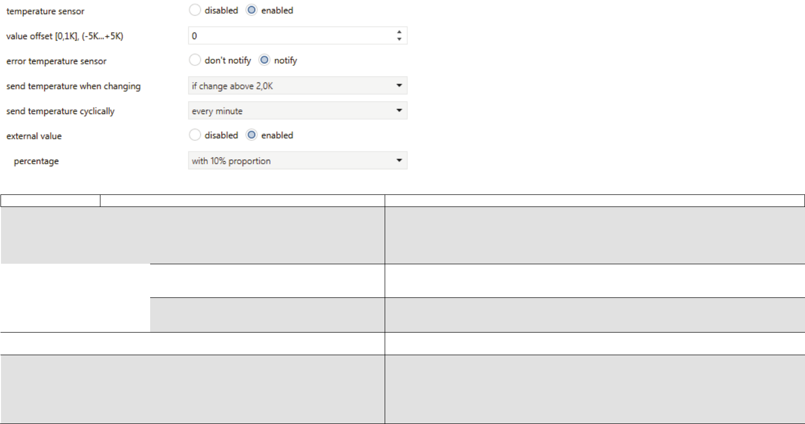
Active
Error humidity sensor
notify
don’t notify
If there are no new values provided from the sensor for more than 10 minutes, the sensor failure
will be reported.
No sensor errors will be reported.
Send relative humidity
when changing
Disabled
If change above 1% –
25%
No function.
The new value is sent if the difference between old and new value is above the defined sending
threshold.
Send relative humidity
Disabled
No function.
cyclically
Every minute – once a
day
Cyclic sending of the recent value.
Value
offset
-5% to +5% ppm
The value is adjusted by this offset. A correction might be necessary in different causes. (e.g.
sensor is placed at an unfavorable position, next to a window).
External value
Inactive
No function.
Active
Percentage:
With xx% proportion
Only use external value
The internal and an external value are taken pro rata to calculate an overall value. This value is
relevant for the control and the sending procedure is as defined above.
It only uses the value from the external sensor. The internal (integrated) sensor will not be used.
TECHNICAL MANUAL GS 3x.10KNX – ENGLISH
21
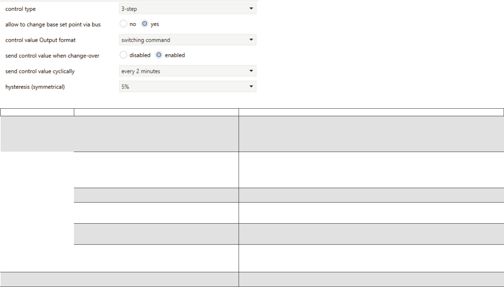
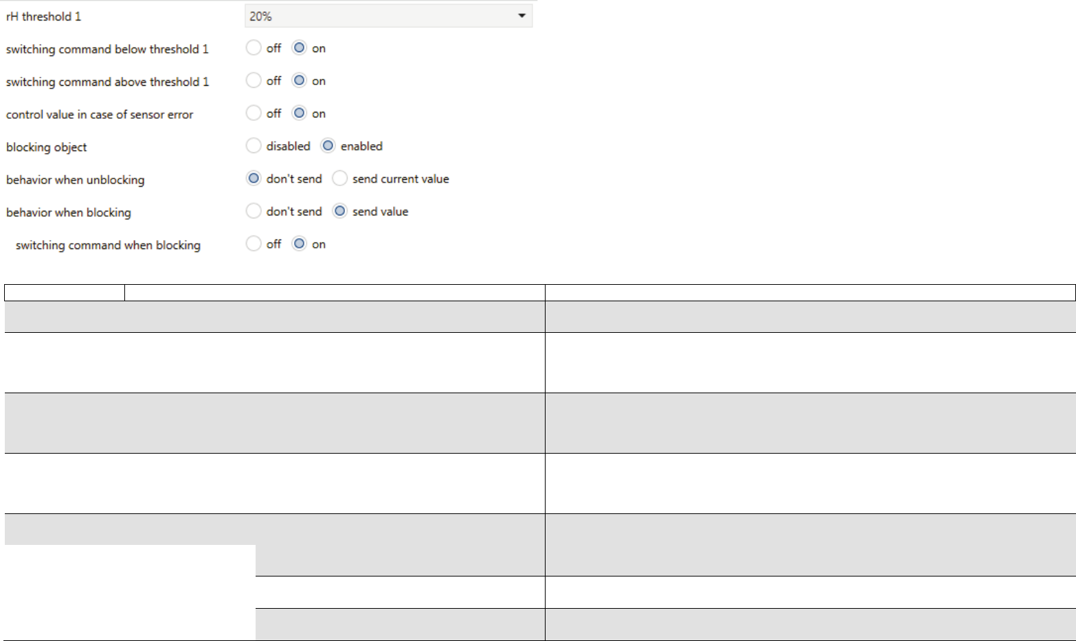
3.Relative humidity control
Designation
Options
Description
Control type
Disabled
Relative humidity control disabled.
1-step
One threshold available – see descriptionchapter 5.1.
2-step
3-step
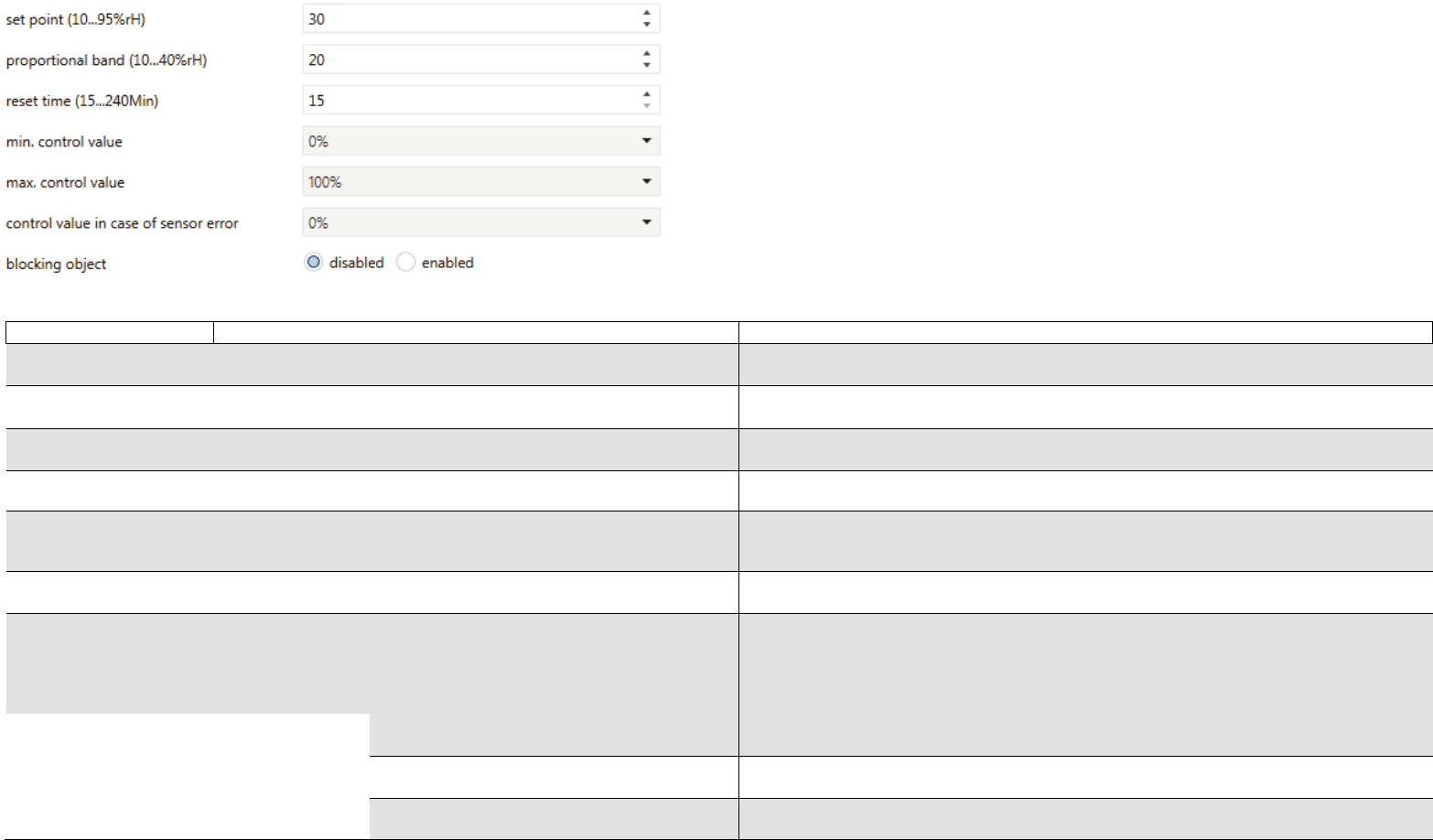
PI
Two thresholds available – see description chapter 5.1.
Three thresholds available – see description chapter 5.1.
PI-Control – see description chapter 5.2.
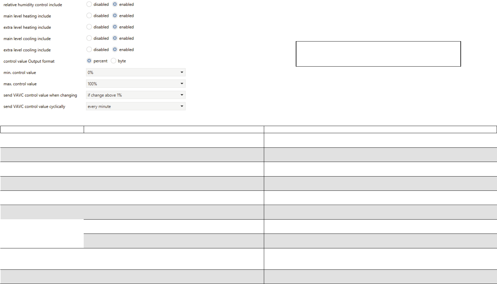
Control value
output format
Switching command
Priority
Percent
Byte
Scene
A switching telegram is sent. There is one object available for every stage.
A priority telegram is sent. There is one object available for every stage.
A percentage value is sent. All steps are sending via one object.
A byte value is sent.All steps are sending via one object.
A scene value is sent. All steps are sending via one object.
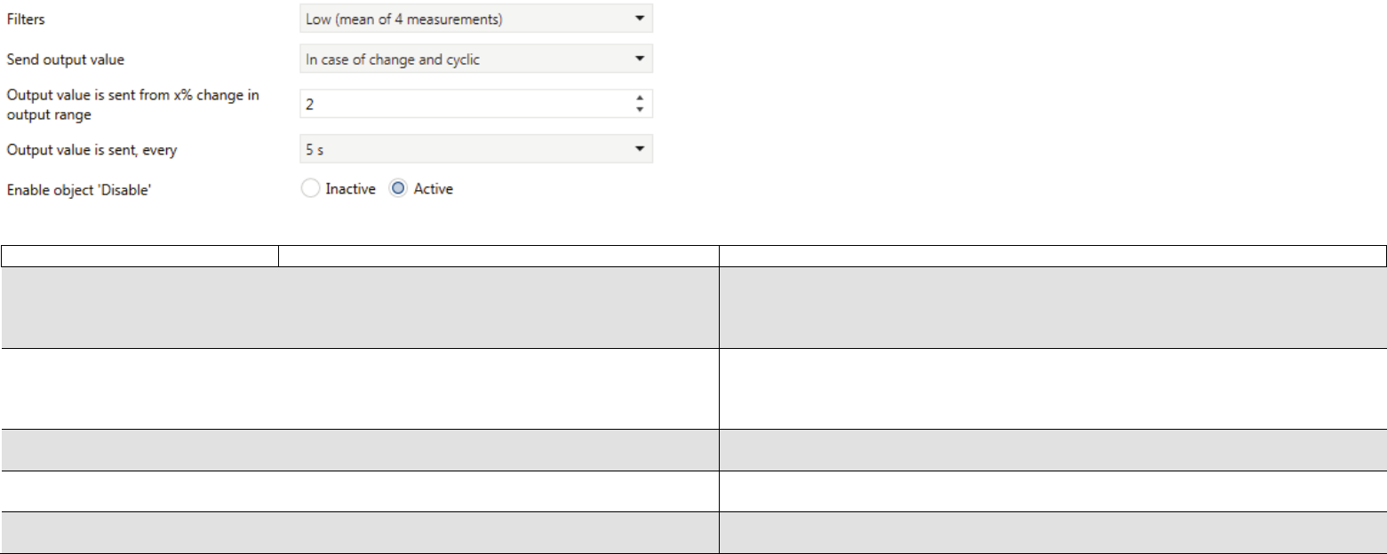
Send control value
when change-over
Disabled
Enabled
No function.
When exceeding or falling below a threshold, a defined object is sent.
Send control value
when changing
(PI control only)
Disabled
If change above 1% … 25%
No function.
If there is a change, the recent control value is sent.
Send control value
cyclically
Disabled
Every two minutes up to 12 hours,
once a day
No function.
Cyclic sending of the recent control value.
Hysteresis
(symmetrical)
(single-stage, two-
stage, three-stage)
1% to 10%
The hysteresis can prevent a frequent switching for fast and small changing values.
Libble takes abuse of its services very seriously. We're committed to dealing with such abuse according to the laws in your country of residence. When you submit a report, we'll investigate it and take the appropriate action. We'll get back to you only if we require additional details or have more information to share.
Product:
Forumrules
To achieve meaningful questions, we apply the following rules:
First, read the manual;
Check if your question has been asked previously;
Try to ask your question as clearly as possible;
Did you already try to solve the problem? Please mention this;
Is your problem solved by a visitor then let him/her know in this forum;
To give a response to a question or answer, do not use this form but click on the button 'reply to this question';
Your question will be posted here and emailed to our subscribers. Therefore, avoid filling in personal details.
Register
Register getting emails for Muller GS 30.10 knx at:
new questions and answers
new manuals
You will receive an email to register for one or both of the options.
Get your user manual by e-mail
Enter your email address to receive the manual of Muller GS 30.10 knx in the language / languages: English as an attachment in your email.
The manual is 1,89 mb in size.
You will receive the manual in your email within minutes. If you have not received an email, then probably have entered the wrong email address or your mailbox is too full. In addition, it may be that your ISP may have a maximum size for emails to receive.
If you have not received an email with the manual within fifteen minutes, it may be that you have a entered a wrong email address or that your ISP has set a maximum size to receive email that is smaller than the size of the manual.
The email address you have provided is not correct.
Please check the email address and correct it.
Your question is posted on this page
Would you like to receive an email when new answers and questions are posted? Please enter your email address.