694156
6
Zoom out
Zoom in
Previous page
1/54
Next page
USE AND MAINTENANCE
MANUAL
Downloaded from www.Manualslib.com manuals search engine
EN 14785 - 2006
Potencia nominal:
Potência nominal:
Nominal heat output:
Brændværdi:
Emisn CO ( al 13% de O2):
Emiso CO (13% de O2):
CO emission (at 13% O2)
CO emission (ved 13% O2):
Eficiencia:
Eficiencia:
Efficiency:
Virkningsgrad:
Temperadura humos:
Tempretura dos fumos:
Flue
g
as temperature:
gg
astemperatur:
Asorbimiento electrico max:
Max. elektrisk e
ff
ekt:
Tensión de funcionamiento:
Tensão electrica
f
uncionamento:
Rated volta
g
e:
Netsndin
g
:
Distancias de seguridad (retro):
Distancia de segurança (trasiera):
Safety clarence distance (back):
Sikkerhedsafstand (bag):
Distancias de seguridad (laterales):
Distancia de segurança (lateral):
Safety clarence distance (side):
Sikkerhedsafstand
side
:
MCZ S.p.A. - Via G.Oberdan 86, I - 33074 Vigonovo (PN) Italy.
09
Art. 15a B-VG - VKF AEAI
Regensburger und Münchener BStV erfüllt.
EGO AIR / STAR AIR
Max
Min
Potência electrica absorbida:
Max. electrical power suppl
y
:
8,0 kW
2,4 kW
P max
P min
0,014%
0,025%
P max
P min
91,7%
94,1%
Utilizar lo con combustibles adaptados. Utilizar somente combustivel adaquado.
Use only recommended fuels. Anvend kun anbefalede brændsler.
Leer y seguir las instrucciones! Leia atentamente e siga as
instruções! Leggere e seguire le istruzioni! Read and follow the
operating instructions!lg fabrikantens brugervejledning!
COD: 8900903900
230 V - 50 Hz.
50 mm
100 mm
Producto conforme a la instalación de tubos múltiples. Produto conforme para
instalação em condutas multiplas. Appliance suitable for installation in a shared flue.
Apparatet kan bruges i en røggassamleledning.
170 °C
420 W
(Med. 80 W)
Downloaded from www.Manualslib.com manuals search engine
PELLET STOVES
Contents
INSTALLATION AND USE MANUAL
page 3
Contents Technical service - Rights reserved MCZ S.p.A. - Reproduction prohibited
INTRODUCTION ....................................................................................................................................5
1. WARNINGS AND GUARANTEE CONDITIONS.....................................................................................6
1.1. SAFETY INSTRUCTIONS..................................................................................................................6
1.2. OPERATING WARNINGS..................................................................................................................7
1.3. GUARANTEE CONDITIONS ..............................................................................................................8
1.3.1. Limitations...............................................................................................................................8
1.3.2. Exclusions................................................................................................................................8
2. THEORETICAL NOTIONS FOR INSTALLATION ................................................................................10
2.1. Pellets..........................................................................................................................................10
2.2. PRECAUTIONS FOR INSTALLATION................................................................................................11
2.3. OPERATING AREA.........................................................................................................................11
2.4. CONNECTION TO THE EXTERNAL AIR INTAKE................................................................................12
2.5. CONNECTION OF SMOKE DISCHARGE PIPE ....................................................................................13
2.6. CONNECTION TO THE FLUE PIPE...................................................................................................14
2.7. CONNECTION TO AN EXTERNAL FLUE WITH INSULATED OR DOUBLE-WALL PIPE.............................14
2.8. CONNECTION TO THE FLUE PIPE...................................................................................................14
2.9. OPERATING PROBLEMS CAUSED BY DRAUGHT DEFECTS IN THE FLUE.............................................15
3. INSTALLATION AND ASSEMBLY......................................................................................................16
3.1. DRAWINGS AND TECHNICAL CHARACTERISTICS ............................................................................16
3.1.1. STAR Air................................................................................................................................16
3.1.2. EGO Air .................................................................................................................................16
3.1.3. Technical characteristics .........................................................................................................17
3.2. PREPARATION AND UNPACK ING...................................................................................................18
3.3. LATERAL CLADDING ASSEMBLY.....................................................................................................20
3.4. INSTALLATION OF AIR FILTER ......................................................................................................22
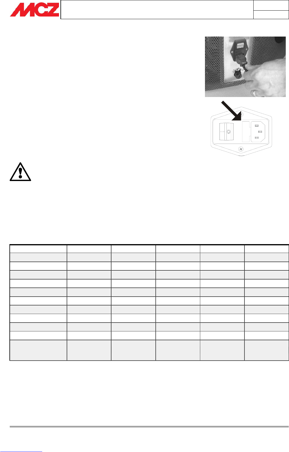
3.5. MAKING THE ELECTRICAL CONNECTIONS......................................................................................22
4. OPERATION .....................................................................................................................................23
4.1. PRE-LIGHTING WARNINGS............................................................................................................23
4.2. PRE-LIGHTING CHECK ..................................................................................................................24
4.3. LOADING THE PELLETS.................................................................................................................24
4.4. CONTROL PANEL/REMOTE CONTROL DISPLAY (accessory)..............................................................25
4.4.1. Control panel logic..................................................................................................................25
4.4.2. Remote control (accessory).....................................................................................................27
4.4.3. General characteristics of the LCD remote control .....................................................................28
4.4.4. Type of batteries and replacement...........................................................................................28
4.5. SETTINGS TO CARRY OUT BEFORE FIRST LIGHTING ......................................................................28
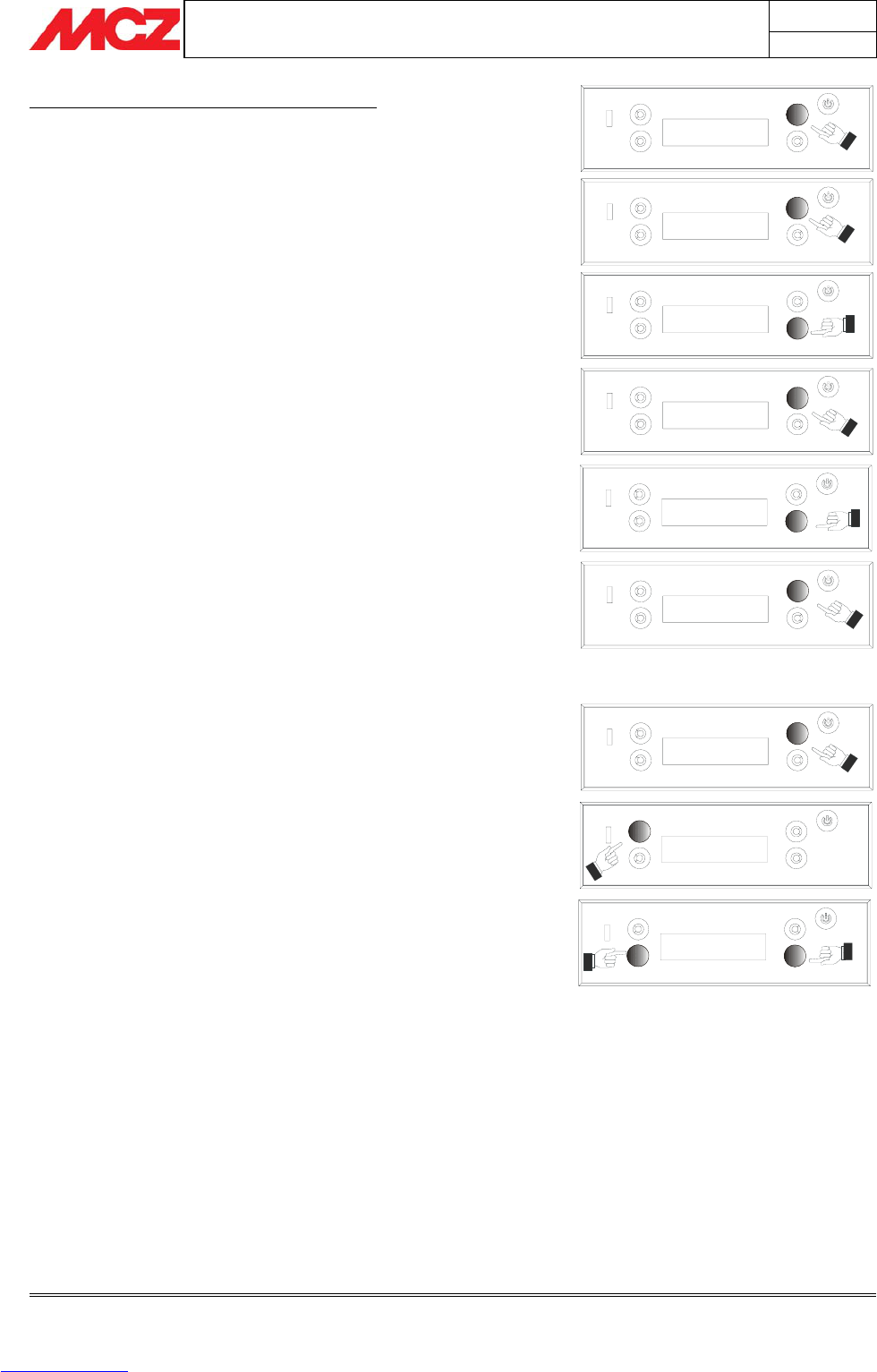
4.5.1. Setting current day and time...................................................................................................29
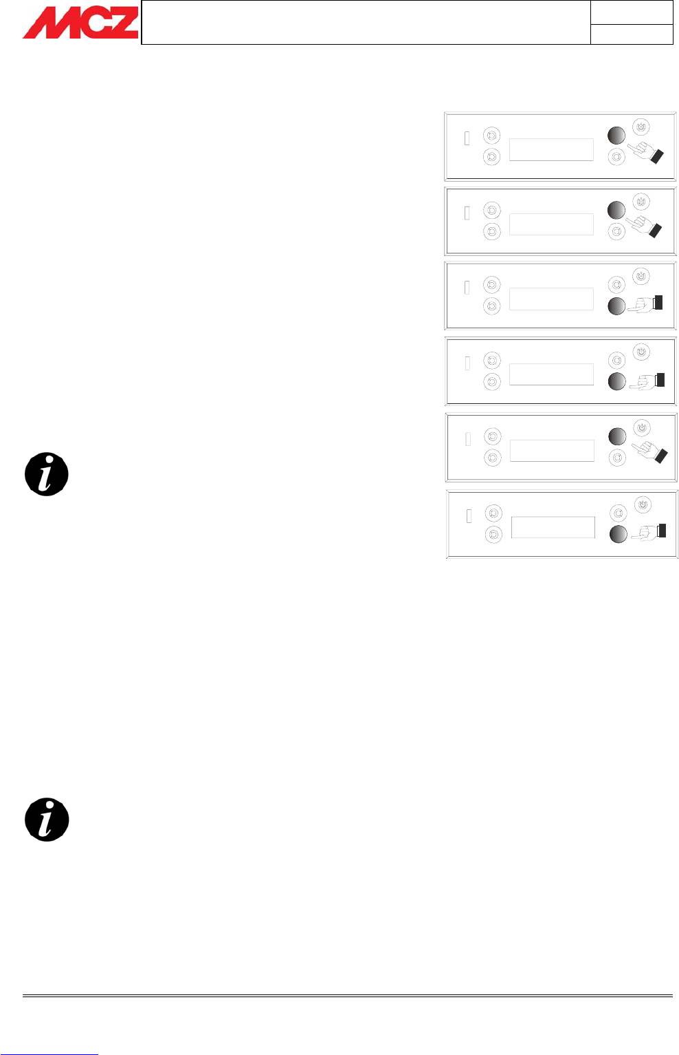
4.5.2. Setting the language ..............................................................................................................31
4.6. FIRST LIGHTING ..........................................................................................................................32
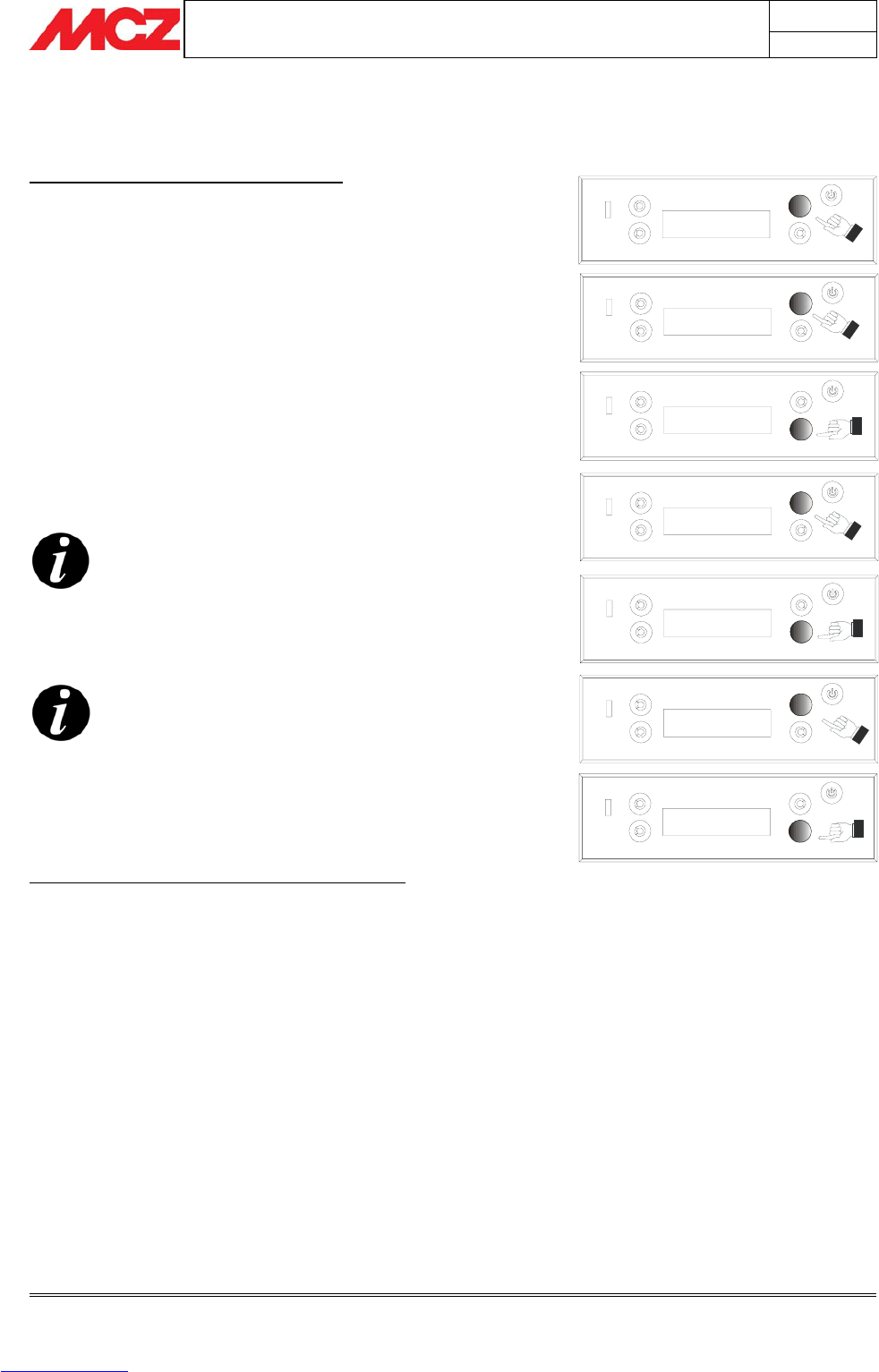
4.6.1. ON/OFF from the control panel or remote control (if purchased) ................................................32
4.6.2. Note on first ignition...............................................................................................................32
4.7. OPERATING MODE........................................................................................................................32
4.7.1. Manual and automatic ............................................................................................................32
4.7.1.1.
Changing from manual to automatic mode
.........................................................................33
4.7.2. Manual mode.........................................................................................................................33
4.7.3. Automatic mode.....................................................................................................................33
4.7.3.1. Room sensor...................................................................................................................34
4.7.3.2. External environment thermostat connection......................................................................34
4.7.4. Automatic mode with AUTO-ECO.............................................................................................35
4.7.4.1.
Activation /de-activation of AUTO-ECO mode
.....................................................................36
4.8. HOT AIR VENTILATION.................................................................................................................37
4.9. SLEEP FUNCTION .........................................................................................................................38
4.10. TIMER......................................................................................................................................38
Downloaded from www.Manualslib.com manuals search engine
PELLET STOVES
Contents
INSTALLATION AND USE MANUAL
page 4
Contents Technical service - Rights reserved MCZ S.p.A. - Reproduction prohibited
4.10.1. Current date and clock ........................................................................................................38
4.10.2. TIMER activation and selection of a programme. ...................................................................39
4.10.3. TIMER de-activation............................................................................................................40
4.11. PRE-SET WEEKLY AND DAILY PROGRAMMES...............................................................................40
4.11.1. Weekly programmes............................................................................................................40
4.11.2. Daily programmes...............................................................................................................42
4.12. PRACTICAL EXAMPLE OF DAILY PROGRAMMING..........................................................................43
4.12.1. Setting of a daily programme...............................................................................................43
4.13. SAFETY DEVICES.......................................................................................................................43
4.14. ALARM SIGNALLING ..................................................................................................................44
4.15. Exiting alarm condition...............................................................................................................46
4.15.1. Shutdown of the stove ........................................................................................................46
5. MAINTENANCE AND CLEANING ......................................................................................................47
5.1. DAILY AND WEEKLY CLEANING BY THE USER.................................................................................47
5.1.1. Before each lighting................................................................................................................47
5.1.2. Check every 2/3 days .............................................................................................................47
5.1.3. Cleaning the glass ..................................................................................................................48
5.1.4. Cleaning of the air filter ..........................................................................................................48
5.2. PERIODIC CLEANING BY A SPECIALISED TECHNICIAN ....................................................................49
5.2.1. Cleaning of the heat exchanger ...............................................................................................49
5.2.2. Shutting the stove down (end of season) .................................................................................50
5.2.3. Check of internal components .................................................................................................50
6. PROBLEMS / CAUSES / SOLUTIONS ...............................................................................................51
7. ELECTRICAL DIAGRAMS..................................................................................................................53
Downloaded from www.Manualslib.com manuals search engine
PELLET STOVES Chapter 1
INSTALLATION AND USE MANUAL
page 5
Introduction Technical service - Rights reserved MCZ S.p.A. - Reproduction prohibited
INTRODUCTION
Dear Customer,
We wish to thank you for choosing an MCZ product, specifically a stove
of the MCZ pellet line.
In order to get the best performance from your stove and to
enjoy to the full the warmth and the sense of well-being which
the flame will diffuse through the home, we recommend that
you read this booklet carefully before lighting the s
tove for the first time.
While thanking you again, may we remind you that the stove MUST
NOT be used by children, and that they must always be kept at a safe
distance from it!
Revisions to the publication
In order to improve the product, to keep this publication up to date the
manufacturer reserves the right to make modifications without any
advance notice. Any reproduction, even in part, of this manual without
the consent of the manufacturer is prohibited.
Care of the manual and how to consult it
Take good care of this manual and keep it in a place which can
easily and quickly be reached.
If this manual should be lost or destroyed, or if it is in poor
condition, ask for a copy from your retailer or directly from the
manufacturer, providing product identification data.
Information which is essential or that requires special attention is
shown in bold text.
Italic text
is used to call your attention to other paragraphs in the
manual or for any additional clarifications.
SYMBOLS USED IN THE MANUAL
ATTENTION
This warning sign indicates that the message to which it
refers should be carefully read and understood, because
failure to comply with what these notices say can cause
serious damage to the stove and put the user's safety at
risk.
INFORMATION
This symbol is used to highlight information which is
important for proper stove operation. Failure to comply with
these provisions will compromise use of the stove and its
operation will not be satisfactory.
OPERATING SEQUENCES:
Indicates a sequence of buttons to be pushed to access
menus or to make adjustments.
MANUAL
Indicates that you should carefully read this manual or the
related instructions.
Downloaded from www.Manualslib.com manuals search engine
PELLET STOVES Chapter 1
INSTALLATION AND USE MANUAL
page 6
Warnings and guarantee conciliations Technical service - Rights reserved MCZ S.p.A. - Reproduction prohibited
1. WARNINGS AND GUARANTEE CONDITIONS
1.1. SAFETY INSTRUCTIONS
Installation of the stove, making the electrical
connections, checking its operation, and
maintenance are all tasks which should be carried
out by qualified and authorised personnel.
Install the stove in accordance with the
regulations in force in your local area, region and
country.
For the correct use of the stove and of the electronic
apparatus connected to it, and to prevent accidents, the
instructions given in this booklet must always be
followed.
Use, adjustment and programming must be carried out
by adults. Errors or incorrect settings may cause
hazardous conditions and/or poor operation.
Before beginning any operation, the user, or whoever is
preparing to operate on the stove, must have read and
understood the entire contents of this instruction
booklet.
The stove is to be used only for its intended purpose.
Any other use is to be considered improper and
therefore hazardous.
Do not use the stove for standing on or as any kind of
support.
Do not put clothes to dry on the stove Any clothes
hangers and suchlike must be kept a suitable distance
from the stove. Danger of fire.
All responsibility for improper use is taken entirely by
the user and such use relieves MCZ of any civil or
criminal responsibility.
Any kind of tampering or unauthorised substitution of
non-original spare parts can be hazardous for the safety
of the operator and relieves MCZ of any civil or criminal
responsibility.
Most of the surfaces of the stove are extremely hot (the
door, the handle, the glass, smoke discharge pipes etc.).
Avoid coming into contact with these parts, therefore,
without adequate protective clothing or suitable
implements, such as gloves with thermal protection or
implements which keep the hands cool.
Carefully explain this hazard to elderly people, disabled
people and particularly to all children, keeping them
away from the stove while it is running.
Under no circumstances should the stove be run
with the door open or the glass broken.
Do not touch the stove with wet hands, in view of the
fact that it is an electrical appliance. Always disconnect
the supply cable before doing anything to the unit.
Before carrying out any cleaning or maintenance
operation, make sure in advance that the stove is
disconnected from the mains electricity supply, by
Downloaded from www.Manualslib.com manuals search engine
PELLET STOVES Chapter 1
INSTALLATION AND USE MANUAL
page 7
Warnings and guarantee conciliations Technical service - Rights reserved MCZ S.p.A. - Reproduction prohibited
turning off the main switch located on the back of the
stove, or by unplugging the supply cable.
The stove must be connected to an electrical system
which is equipped with an earth conductor, as laid down
in directives 73/23 EEC and 93/98 EEC.
The system must be of adequate rated capacity for the
stated electrical power of the stove.
Incorrect installation or faulty maintenance (not
conforming to the requirements set out in this booklet)
can cause harm to people, animals or property. In such
cases MCZ is absolved from any civil or criminal
responsibility.
1.2. OPERATING WARNINGS
Shut the stove down in the event of a breakdown or
bad running.
Pellets must not be fed manually into the burner.
Accumulated unburnt pellets in the burner after
repeated failed ignitions must be removed before
lighting.
Do not wash the inside of the stove with water.
Do not wash the stove with water. The water could get
inside the unit and damage the electrical insulation and
cause electric shocks.
Do not expose your own body to hot air for extended
periods. Do not overheat the room you are in and
where the stove is installed. This could cause injuries
and health problems.
Do not expose plants or animals directly to a current of
hot air. Both plants and animals could be harmed by it.
Do not put any fuels in the hopper but wood pellets.
Install the stove in a location which is suitable for
firefighting, and equipped with all services such as air
and electricity supply and provision for discharging
combustion gases.
If there is a fire in the flue pipe, extinguish the stove,
disconnect it from the power supply and never open
the door. Then contact the competent authorities.
If the stove and the ceramic cladding are in storage, it
should be in a place that is free of damp, and they
should not be exposed to extremes of temperature.
It is inadvisable to base the stove directly on the floor,
and if the floor is made of flammable material, it must
be suitably insulated.
Do not light the stove with flammable materials if the
ignition system breaks down.
INFORMATION
In case of any problems, get in touch with your dealer, or
a qualified engineer authorised by MCZ, and if a repair is
necessary, insist on the use of original spare parts.
Use only the fuel recommended by MCZ (for Italy pellets
Downloaded from www.Manualslib.com manuals search engine
PELLET STOVES Chapter 1
INSTALLATION AND USE MANUAL
page 8
Warnings and guarantee conciliations Technical service - Rights reserved MCZ S.p.A. - Reproduction prohibited
with a diameter of 6 mm and for other European
countries with a diameter of 6-8 mm) and provided only
with an automatic supply system.
Periodically check and clean the smoke outlet ducts
(connection to the flue pipe).
Accumulated unburnt pellets in the burner after
repeated failed ignitions must be removed before
lighting.
The pellet stove is not a cooking appliance.
Always keep the cover of the fuel hopper closed.
Keep this instruction manual carefully because it must
stay with the stove throughout its working life. If the
stove is sold or transferred to another user, always
make sure that the booklet goes with the product.
If it gets lost, ask MCZ or your authorised dealer for
another copy.
1.3. GUARANTEE CONDITIONS
MCZ guarantees the stove, excluding the components
which are subject to normal, for a period of two years
from the date of purchase, as proved by a supporting
document which gives the name of the vendor and the date
on which the sale took place. The guarantee is conditional
on the guarantee certificate being filled in and returned
within 8 days, and requires that the product be installed and
tested by a specialised installer, according to the detailed
instructions given in the instruction booklet supplied with the
product.
The term 'guarantee' is to be understood to denote the free-
of-charge replacement or repair of parts recognised to
have been defective at the start by reason of
manufacturing defects.
1.3.1. Limitations
The above guarantee does not cover components relating to electrical
and electronic parts, or fans, on which the guarantee period is 1 year
from the purchase of the product, documented as specified above. The
guarantee does not cover parts subject to normal wear such as
gaskets, glass, and any parts with can be removed from the firebox.
The replacement parts will be guaranteed for the remainder of the
guarantee period starting from the date of purchase of the product.
1.3.2. Exclusions
Variations in colour in the painted or ceramic parts, and crackling of the
glaze on the ceramics, do not constitute grounds for a claim under the
guarantee, as they are natural characteristics of the material and of the
use of the product.
The guarantee does not cover any parts which may be found to be
faulty as a result of negligence or carelessness in use, or of incorrect
maintenance, or of installation not complying with MCZ's specification
(see the relevant chapters in this user manual).
MCZ refuses to accept any responsibility for any damage which may be
caused, directly or indirectly, by persons, animals or things in
consequence of the failure to observe all the prescriptions laid down in
Downloaded from www.Manualslib.com manuals search engine
PELLET STOVES Chapter 1
INSTALLATION AND USE MANUAL
page 9
Warnings and guarantee conciliations Technical service - Rights reserved MCZ S.p.A. - Reproduction prohibited
the instruction booklet, especially those concerning warnings on the
subject of installation, use and maintenance of the appliance.
If the product does not perform correctly, contact your local retailer
and/or importer.
Damage caused by transport and/or handling is excluded from the
guarantee.
For installation and use of the product, reference must be made
exclusively to the booklet supplied.
The guarantee will be invalidated in the event of damage caused by
tampering with the appliance, atmospheric agents, natural disasters,
electrical discharges, fire, defects in the electrical system, and caused
by lack of, or incorrect, maintenance in terms of the manufacturer's
instructions.
CLAIMS UNDER THE GUARANTEE
the request for action under the guarantee must be
addressed to the retailer, who will forward the claim
to MCZ's technical assistance service.
MCZ DECLARES THAT THE STOVE WHICH YOU HAVE
PURCHASED COMPLIES WITH EEC DIRECTIVE
89/336 and 72/23 and SUCCESSIVE AMENDMENTS
MCZ refuses to accept any responsibility in the event
that the stove or any other accessory have been
improperly used or modified without authorisation.
For all replacement of parts, only original MCZ spare
parts must be used.
Downloaded from www.Manualslib.com manuals search engine
PELLET STOVES Chapter 2
INSTALLATION AND USE MANUAL
page 10
Theoretical notions for installation Technical service - Rights reserved MCZ S.p.A. - Reproduction prohibited
2. Theoretical notions for installation
2.1. Pellets
Wood pellets are manufactured by hot-extruding compressed sawdust which
is produced during the working of natural dried wood. The compactness of
the material comes from the lignin which is contained in the wood itself, and
allows the production of pellets without the use of glues or binders.
The market offers different types of pellet with characteristics which
vary depending on what mixture of woods is used. The diameter varies
between 6 mm and 8 mm, with a standard length in the range 5 mm to
30 mm. Good quality pellets have a density which varies between 600
kg/m3 and 750 kg/m3, with a moisture content which varies from 5%
to 8% by weight.
Besides being an ecological fuel (exploiting timber residues to the
maximum and achieving cleaner combustion than is possible with fossil
fuels), pellets also have technical advantages. While good-quality
timber has a calorific power of 4.4 kW/kg (with 15% moisture,
therefore after about 18 months' seasoning), the equivalent figure for
pellets is 4,9 kW/kg.
To ensure good combustion, the pellets must be stored in an area that
is free of humidity and protected from dirt. The pellets are usually
supplied in 15 kg. sacks, so storing them is very convenient.
Good quality pellets ensure good combustion, thus lowering the
emission of harmful agents into the atmosphere.
The poorer the quality of the fuel, the more
frequently will intervention be necessary for cleaning
the internal parts, such as the grate and the
combustion chamber.
The main certifications of quality for pellets in the European market are
DINplus and Ö-Norm M7135; these ensure respect of:
9 Calorific power: 4.9 kW/kg
9 Water content: max 10% of weight
9 Percentage of ashes: max 0,5% of weight
9 Diameter: 5 – 6mm
9 Length: max 30mm
9 Contents: 100% untreated wood, with no added bonding
substances (bark percentage 5% max)
9 Packaging: in sacks made from ecologically compatible or
biologically decomposing material
Fuel pellets
15 Kg sack of fuel
Downloaded from www.Manualslib.com manuals search engine
PELLET STOVES Chapter 2
INSTALLATION AND USE MANUAL
page 11
Theoretical notions for installation Technical service - Rights reserved MCZ S.p.A. - Reproduction prohibited
MCZ strongly recommends using certified fuel in its
stoves (DINplus e Ö-Norm M7135).
The use of fuel of inferior quality or not conforming
to the specification given above compromises the
running of your stove and can therefore lead to the
termination of the guarantee and of the
manufacturer's responsibility for the product.
MCZ pellet stoves run exclusively on pellets with a
diameter of 6 mm (only for Italy) and 6-8 mm
(European countries) with lengths that go from 5
mm to 30 mm.
2.2. PRECAUTIONS FOR INSTALLATION
IMPORTANT!
Installation and assembly of the stove must be
carried out by qualified personnel.
The stove must be installed in a suitable position to allow the normal
operations of opening and ordinary maintenance.
The site must be:
capable of providing the environmental conditions for operation
equipped with power supply 230V 50 Hz (EN73-23)
capable of taking an adequate system for smoke discharge
provided with external ventilation
provided with an earth connection complying with CEI 64-8
The stove must be connected to a flue pipe or an internal or
external vertical duct conforming to current standards UNI
7129 - 7131 9615.
The stove must be positioned in such a way that the electrical
plug is accessible.
IMPORTANT!
The stove must be connected to a flue pipe or a
vertical duct which can discharge the fumes at the
highest point of the building.
The fumes are however derived from the combustion
of wood products, and if they come into contact with
or close to walls, they can make dirty marks.
Also take care because the fumes are very hot but
almost invisible, and can cause burns on contact.
The holes for the passage of the smoke pipe and for
the intake of air from outside should be made before
positioning the stove unit.
2.3. OPERATING AREA
For proper functioning and a good temperature distribution, the stove
should be positioned in a location where it is able to take in the air
necessary for combustion of the pellets (about 40 m
3
/h must be
Downloaded from www.Manualslib.com manuals search engine
PELLET STOVES Chapter 2
INSTALLATION AND USE MANUAL
page 12
Theoretical notions for installation Technical service - Rights reserved MCZ S.p.A. - Reproduction prohibited
available), as laid down in the standard governing the installation and
in accordance with local national standards.
The volume of the room must not be less than 30 m
3.
The air must come in through permanent openings made in walls (in
proximity to the stove) which give onto the outside, with a minimum
cross-section area of 100 cm
2.
These openings must be made in such a way that it is not possible for
them to be obstructed in any way.
Alternatively, the air can be taken from rooms adjacent to the one
which needs ventilating, as long as they are provided with an air intake
from the outside, and are not used as bedrooms or bathrooms, and
provided there is no fire risk such as there is for example in garages,
woodsheds, and storerooms, with particular reference to what is laid
down in current standards.
It is not permissible to install the stove in bedrooms,
bathrooms, or in a room where another heating
appliance is installed (fireplace, stove etc.) which
does not have its own independent air intake.
Locating the stove in a room with an explosive
atmosphere is prohibited.
The floor of the room where the stove is to be
installed must be strong enough to take its weight.
If the walls are not flammable, position the stove with a clearance to
the rear of at least 10 cm.
For flammable walls, keep a minimum distance of 20 cm at the rear, 10
cm on the sides and 150 cm at the front.
If the room contains objects which are believed to be particularly
delicate, such as drapes, sofas and other furniture, their distance from
the stove should be considerably increased.
If the flooring is made of wood, provide a floor
protection surface in compliance with current
national standards.
2.4. CONNECTION TO THE EXTERNAL AIR INTAKE
It is essential that at least as much air must be able to flow into the
room where the stove is installed as is required for proper combustion
in the appliance and for the ventilation of the room. This can be
effected by means of permanent openings in the walls of the room to
be ventilated, which give onto the outside, or by single or collective
ventilation ducts.
For this purpose, on the external wall near the stove, a hole must be
made with a minimum free cross-section of 100 cm². (equivalent to a
round hole of 12 cm diameter or a square hole 10x10 cm), protected by
a grille on the inside and the outside.
The air intake must also:
communicate directly with the room where the stove is installed
be protected by a grille, metal mesh or suitable guard, as long as
this does not reduce the area below the minimum.
be positioned in such a way as to be impossible to obstruct
150 cm
20 cm
20 cm
Example of pellet stove installation
Downloaded from www.Manualslib.com manuals search engine
PELLET STOVES Chapter 2
INSTALLATION AND USE MANUAL
page 13
Theoretical notions for installation Technical service - Rights reserved MCZ S.p.A. - Reproduction prohibited
2
1
It is not compulsory to connect the air intake directly
with the stove (so that it draws air directly from
outside), but it is essential at all events to ensure an
airflow of 50 cubic metres per hour by the use of a
hole of the dimensions given.
See standard UNI 10683.
2.5. CONNECTION OF SMOKE DISCHARGE PIPE
When making the hole for the passage of the smoke discharge pipe, it
is necessary to take into account the possible presence of flammable
materials. If the hole will be going through a wall made of wood or any
other material which is sensitive to heat, the INSTALLER MUST first
of all use the special wall union (diam.13cm 13cm minimum) and
properly insulate the pipe of the stove that passes through it, using
adequate insulation materials (thickness 1.35cm with minimum thermal
conductivity of 0.07 W/m°K).
The same is true if the stove pipe must run through vertical or
horizontal stretches passing in proximity (min.20cm) to the heat-
sensitive wall
As an alternative we recommend the use of insulated pipe, which can
also be used on the outside to avoid condensation.
The combustion chamber works in low pressure. The smoke duct for
the discharge of fumes will also be under low pressure when connected
to an efficient flue pipe as directed.
Pipes and unions with suitable gaskets must always
be used, to guarantee a hermetic seal.
All sections of the smoke duct must be inspectable and
removable to enable periodic internal cleaning. Tee
connectors with inspection caps should be used.
Position the stove bearing in mind all the instructions and
considerations above.
IMPORTANT!
All 90 degree changes of direction in the flue pipe
must be fitted with suitable tee connectors to allow
the possibility of inspection. (see accessories for
pellet stove)
It is absolutely prohibited to fit a grille on the end of
the discharge pipe, because it could lead to poor
running of the stove.
FOR CONNECTION TO THE FLUE PIPE, NOT MORE
THAN 2-3 METRES OF HORIZONTAL PIPE MUST BE
USED AND NOT MORE THAN THREE 90° CURVES
MUST BE USED
IT IS ALSO ADVISABLE NOT TO EXCEED 6 METRES IN
LENGTH WITH THE PIPE Ø 80 mm
Example of pellet stove installation
Rear view of a pellet stove
1) Combustion air intake
2) Smoke outlet
3-5 %
2 - 3 mt. MAX
H
>
4
m
t
.
H
>
1
,
5
m
t
.
Downloaded from www.Manualslib.com manuals search engine
PELLET STOVES Chapter 2
INSTALLATION AND USE MANUAL
page 14
Theoretical notions for installation Technical service - Rights reserved MCZ S.p.A. - Reproduction prohibited
2.6. CONNECTION TO THE FLUE PIPE
The flue pipe must have internal dimensions not larger than 20 x 20
cm, or diameter 20 cm. In the event of larger dimensions, or of the
flue pipe being in poor condition (for example cracks, poor insulation,
etc.), it is advisable to fit a stainless steel pipe of suitable diameter
inside the flue pipe throughout its length, right up to the top.
Check with suitable instruments that there is a minimum draught of 10
Pa.
At the bottom of the flue pipe, provide an inspection cap to allow
periodic checking and cleaning, which must be done annually.
Make a gas-tight connection to the flue pipe, using pipes and
connectors as recommended by us.
You must ensure that a windproof cowl should be fitted which complies
with the standards in force.
This type of connection ensures the evacuation of the
fumes even in the event of a temporary power cut.
2.7. CONNECTION TO AN EXTERNAL FLUE WITH
INSULATED OR DOUBLE-WALL PIPE
The external fluepipe must have internal dimensions of minimum
10x10 cm or 10 cm diameter, and maximum 20x20 cm or 20 cm
diameter.
Check with suitable instruments that there is a minimum draught of 10 Pa.
The only type of pipe which is permissible is insulated (double-walled)
stainless steel, smooth on the inside, fixed to the wall. Flexible stainless
steel pipe must not be used. At the bottom of the flue pipe, provide an
inspection cap to allow periodic checking and cleaning, which must be
done annually. Make a gas-tight connection to the flue pipe, using
pipes and connectors as recommended by us.
You must ensure that a windproof cowl should be fitted which complies
with the standards in force.
This type of connection ensures the evacuation of the
fumes even in the event of a temporary power cut.
2.8. CONNECTION TO THE FLUE PIPE
For proper functioning, the connecting pipe between the stove and the
chimney or flue duct must have a slope of not less than 3% in the
horizontal stretches, the length of which must not exceed 2/3
metres, and the vertical distance between one tee connector and
another (change of direction) must not be less than 1.5m.
Check with suitable instruments that there is a minimum draught of 10
Pa.
At the bottom of the flue pipe, provide an inspection cap to allow
periodic checking and cleaning, which must be done annually.
Make a gas-tight connection to the flue pipe, using pipes and
connectors as recommended by us.
You must ensure that a windproof cowl should be fitted which complies
with the standards in force.
0,5 mt.
1
2
3
1) Windproof cowl
2) Flue pipe
3) Inspection
0,5 mt.
2
1
3
1) Windproof cowl
2) Flue pipe
3) Inspection
3-5 %
2 - 3 mt. MAX
0,5 mt.
H
>
1
,
5
m
t
.
3
2
1
1) Windproof cowl
2) Flue pipe
3) Inspection
Downloaded from www.Manualslib.com manuals search engine
PELLET STOVES Chapter 2
INSTALLATION AND USE MANUAL
page 15
Theoretical notions for installation Technical service - Rights reserved MCZ S.p.A. - Reproduction prohibited
This type of connection ensures the evacuation of the
fumes even in the event of a temporary power cut.
2.9. OPERATING PROBLEMS CAUSED BY DRAUGHT
DEFECTS IN THE FLUE
Of all the weather and geographical conditions which affect the
operation of a flue pipe (rain, fog, snow, altitude a.s.l., exposure to
sunlight, direction of facing), the wind is unquestionably the most
decisive. In fact, along with thermal depression caused by the
difference in temperature inside and outside of the chimney, there is
another type of depression or over-pressure: dynamic pressure caused
by the wind. An updraft always increases depression and hence
draught. A crosswind increases depression provided the cowl has been
installed properly. A downdraft always decreases depression, at times
inverting it.
Besides the direction and force of the wind, the position of the flue and
the cowl with respect to the roof of the building and the surrounding
landscape is important.
The wind also influences the operation of the chimney indirectly by
creating high-pressure and low-pressure zones, not only outside the
building but inside as well. In rooms directly exposed to the wind (2),
an indoor high-pressure area can be created which can augment the
draught in stoves and fireplaces, but it can be counteracted by the
external high pressure if the cowl is situated on the side exposed to the
wind (1). On the other hand, in the rooms on the opposite side from
the direction of the wind (3), a dynamic depression can be created
which competes with the natural thermal depression developed by the
chimney, but this can be compensated for (sometimes) by locating the
flue on the opposite side from the direction of the wind (4).
IMPORTANT!
The operation of the pellet stove is noticeabl
y
sensitive to the conformation and position of the flue
which is adopted.
Hazardous conditions can only be overcome by
suitable setting-up of the stove carried out by
qualified MCZ personnel.
1
2 3
4
E.g. Crosswind 2: 8 m/sec
Depression of 30Pa
E.g. Downdraft at 45° of
8m/sec. Overpressure of 17
Pa
1-2 = High-pressure zones
3-4 = Low-pressure zones
WIND
Least favourable points
Most favourable position
WIND
Downdraft
High-pressure
Low-pressure zone
Downloaded from www.Manualslib.com manuals search engine
PELLET STOVES Chapter 3
INSTALLATION AND USE MANUAL
page 16
Installation and fitting Technical service - Rights reserved MCZ S.p.A. - Reproduction prohibited
3. INSTALLATION AND ASSEMBLY
3.1. DRAWINGS AND TECHNICAL CHARACTERISTICS
3.1.1. STAR Air
1055
392,5
187
198
385
213
520
70
530
Ø80
Ø48
11
FILTRO
3.1.2. EGO Air
1055
392,5
187
198
385
213
520
Ø80
Ø48
70
530
11
FILTRO
Downloaded from www.Manualslib.com manuals search engine
PELLET STOVES Chapter 3
INSTALLATION AND USE MANUAL
page 17
Installation and fitting Technical service - Rights reserved MCZ S.p.A. - Reproduction prohibited
3.1.3. Technical characteristics
Technical characteristics Star – Ego Air
Overall thermal power Max. 8 kw / 6880 kcal/h
Overall thermal power Min. 2.4 kw / 2064 kcal/h
Yield at maximum 91,7 %
Yield at minimum 94,1 %
Temperature of exhaust smoke at maximum 170°C
Temperature of exhaust smoke at minimum 100°C
CO at 13%O
²
at minimum and maximum 0.025 — 0.014%
CO
2
at minimum and maximum 4.5% – 9.5%
Mass of smoke at minimum and maximum 4 – 6.5 g/sec
Minimum draught at maximum power 0.10 mbar – 10 Pa
Minimum draught at minimum power 0.05 mbar – 5 Pa
Hopper capacity 37 litres
Fuel pellet type Pellet diameter 6-8 mm. Length range 5-30 mm
Pellet consumption per hour Min ~ 0.6 kg/h * Max. ~ 1.8 kg/h *
Operating time between re-fuelling At min~ 40 h * At max. ~ 13 h *
Heatable volume m
3
172/40 – 196/35 – 229/30 **
Combustion air inlet External diameter 50 mm.
Smoke outlet External diameter 80 mm.
Maximum absorbed electrical power Max. 420 WMed. 80 W
Power supply frequency and voltage 220 Volts / 50 Hz
Net weight 140 kg
Weight with packaging 150 Kg
* Data that may vary depending on the type of pellets used.
**Heatable volume based on demand of cal/m
3
40-35-30 (respectively 40-35-30 Kcal/h for m
3
)
Appliance suitable for installation in a shared flue.
Downloaded from www.Manualslib.com manuals search engine
PELLET STOVES Chapter 3
INSTALLATION AND USE MANUAL
page 18
Installation and fitting Technical service - Rights reserved MCZ S.p.A. - Reproduction prohibited
3.2. PREPARATION AND UNPACK ING
STAR AND EGO stoves are delivered with two different packagings:
9 The EGO stove has one packaging
o It contains the stove and the steel sides with the
profiles (Fig.1)
9 The STAR stove has two packagings
o One contains the stove and the profile for the ceramic
or the soapstone
o One contains the ceramic (fig.2). In this case there will
be a single packaging for the structure (the cardboard
with the ceramics will be placed above the packaging
with the structure)
o or Soapstone (fig.3) (in this case there are two
packagings structure + soapstone pallet)
Open the packaging, remove the four screws that secure the base of
the stove to the pallet, two to the right and two to the left (see figure
4), and position the stove in the selected place, ensuring that it is
complies with the above instructions.
The stove body or unit must always be kept in a vertical position when
moved, and moved only using carts. Special care must be used to
protect the door and the glass from impacts that would damage them.
Moving the product must always be done with care. If possible, unpack
the stove in the area where it is going to be installed.
The materials which make up the packaging are not toxic or harmful,
so no special procedures for disposal by required.
Their storage, disposal or possible recycling are therefore the responsibility
of the final user, in compliance with current legislation on the subject.
Do not store the stove unit or its cladding without their packaging.
Figure 1 – Example of packaging stove
+ steel sides (Ego stove)
Figure 2 - Example of packing for
ceramics
Figure 3 - Example of soapstone
packaging
Figure 4 - Removing packaging screws (in
fi
g
ure E
g
o stove
)
Downloaded from www.Manualslib.com manuals search engine
PELLET STOVES Chapter 3
INSTALLATION AND USE MANUAL
page 19
Installation and fitting Technical service - Rights reserved MCZ S.p.A. - Reproduction prohibited
J
J
Position the stove without its cladding and connect it to the flue pipe.
Use the four adjustable feet (J) to get the stove correctly levelled so
that the smoke outlet (S) is lined up with the connecting pipe (H) .
Once the operations for connection are complete, assemble the
cladding (ceramics or steel sides).
If the stove needs to be connected to a discharge pipe which goes
through the rear wall (to connect up with the flue), take the greatest
care to make sure that the joint is not stressed.
If the smoke outlet of the stove is forced or used
improperly to lift it or position it, the operation of the
stove can be damaged irreparably.
S
H
1. Turn the feet clockwise to
lower the stove
2. Turn the feet counter-
clockwise to lower the
stove
Downloaded from www.Manualslib.com manuals search engine
PELLET STOVES Chapter 3
INSTALLATION AND USE MANUAL
page 20
Installation and fitting Technical service - Rights reserved MCZ S.p.A. - Reproduction prohibited
H
G
I
C
E
D
3.3. LATERAL CLADDING ASSEMBLY
THE 6 CERAMICS AND THE 4 SIDES MADE OF
SOAPSTONE THAT ARE LATERAL TO THE STAR STOVE
ARE ALL THE SAME.
Assembly of profiles to insert steel sides (for EGO stove only)
Remove, on the upper part, the cast iron top (A).
Take the two profiles (B) to be assembled on the front part of the
stove (one to the right and one to the left). Make sure that the profile
(B) at the bottom enters the hole predisposed on the base for securing
purposes, and along the side enters the blade (B1) predisposed in the
stove along its entire height. Once this operation is performed, take the
piece (C) with the two screws (D and E) and secure the profile on the
top part of the stove. The screw (D) must be secured on the upper
sheet metal of the stove, while the screw (E) must be secured on the
area predisposed on the profile (B2).
Take the side (I) and secure it to the upper sheet metal of the stove
with the two screws (G and H) provided.
In the front part it must be inserted in the housing (B3) of the profile
(B).
Repeat the same operation for both sides. Reposition the cast iron top.
Figure 5 - EGO stove steel sides
Downloaded from www.Manualslib.com manuals search engine
PELLET STOVES Chapter 3
INSTALLATION AND USE MANUAL
page 21
Installation and fitting Technical service - Rights reserved MCZ S.p.A. - Reproduction prohibited
Assembly of profiles to insert in the ceramic and soapstone
sides (for STAR stove only)
Remove, on the upper part, the cast iron top (A).
Take the four profiles (B) to be assembled on the front and rear part of
the stove (two to the right and two to the left). Make sure that the
profile (B) at the bottom enters the in correspondence to the two holes
predisposed on the base for securing purposes, and along the side
enters the blade (B1) predisposed in the stove along its entire height.
Once both profiles are assembled on one side, take the piece (C) with
the four screws (D-E-F-G) and secure it on the upper part of the stove
(F-D) and in correspondence to the element predisposed on the profile
(B2) for screws G-E.
At this point take the ceramics (3 per side) or the soapstone (2 per
side) and insert them on the profile (B) in correspondence to the
element (B3) from above downwards.
You are advised to use small felt pads (two on the
right and two on the left) to be applied at the tips of
the ceramics (inwards) in correspondence to the part
of the tile that comes into contact with the sheet
metal profile (B3).
This prevents the ceramic from coming into contact
with the metallic parts of the structure and
compensates any differences in thickness of the tile.
Repeat the same operation for both sides. Reposition the cast iron top.
Figure 6 - STAR stove sides
Downloaded from www.Manualslib.com manuals search engine
PELLET STOVES Chapter 3
INSTALLATION AND USE MANUAL
page 22
Installation and fitting Technical service - Rights reserved MCZ S.p.A. - Reproduction prohibited
3.4. INSTALLATION OF AIR FILTER
Before placing the stove near the wall for connection to the
flue pipe and to the electrical mains, install the air filter
provided with the stove.
The cylindrical filter is composed of a metallic net and is already
installed on the stove
The filter must be inserted on the air inlet pipe Ø 5 cm.
To remove it, slightly loosen the screw with the knob on the air inlet,
insert the filter matching it with the filter groove with the screw of the
knob and then secure it by tightening the knob.
ATTENTION!
Never operate the stove without the air filter. MCZ
shall not be held liable for damage to internal
components if this instruction is not followed.
3.5. MAKING THE ELECTRICAL CONNECTIONS
Connect the supply cable first at the rear of the stove and then to an
electrical outlet on the wall.
The main switch located on the rear of the stove should be switched on
only when you want to light the stove.
If you do not intend to use the stove, it is advisable
to keep it switched off.
Electrical connection of the stove
Installation/removal of air filter
Downloaded from www.Manualslib.com manuals search engine
PELLET STOVES Chapter 4
INSTALLATION AND USE MANUAL
page 23
Operation Technical service - Rights reserved MCZ S.p.A. - Reproduction prohibited
4. OPERATION
4.1. PRE-LIGHTING WARNINGS
Do not touch the stove during the first lighting, as it
is during this phase that the paint sets. If you touch
the paint, you may expose the steel surface.
If necessary, touch up the paint with the aerosol spray in the original
colour (see the section "Accessories for pellet stoves").
It is good practice to provide plenty of ventilation in
the room during the initial lighting, as the stove will
give off a small amount of smoke and smell of paint.
Do not stay near the stove, and as previously mentioned, ventilate the
room. The smoke and the smell of paint will vanish after about one
hour of operation. There are no health risks involved.
The stove will be subject to expansion and contraction during the
stages of lighting and cooling down, and may therefore make slight
creaking noises.
This phenomenon is absolutely normal, the structure being made of
sheet steel, and must not be considered a fault.
It is extremely important to be sure not to take the stove to full heat
straight away, but to bring it gradually up to temperature.
If in manual mode, use low heating powers (for example 1
a
-2
a
-3
a
).
During subsequent use, you will be able to make use of all available
heating power (e.g. 4
a
-5
a
), but remember not to keep the stove
running on full power for more than 60-90 minutes.
In this way you will avoid damage to the ceramic panels, the welds and
the steel structure.
At first lighting the stove is already in manual mode.
At first, it is advisable to use the only low and
medium heating levels (from first to third power
level).
Do not demand full heating
performance straight away!
Try to get familiar with the commands given from the control panel.
Try to memorize the messages that the stove provides on the display.
Downloaded from www.Manualslib.com manuals search engine
PELLET STOVES Chapter 4
INSTALLATION AND USE MANUAL
page 24
Operation Technical service - Rights reserved MCZ S.p.A. - Reproduction prohibited
A
4.2. PRE-LIGHTING CHECK
Check that all the safety conditions described above have been met.
Make sure you have read and completely understood the contents of
this instruction booklet.
Remove any components which might burn from the firebox and from
the glass (various instructions and adhesive labels).
Check that the grate A is properly positioned and rests correctly on the
base.
After long periods of disuse, remove from the hopper (using
a vacuum cleaner with an extension) any remains of
pellets which have lain there for some time, since they may
have absorbed moisture, which changes their original
characteristics and makes them unsuitable for burning.
4.3. LOADING THE PELLETS
Fuel is loaded from the upper part of the stove by opening a door. Pour
the pellets in the hopper. When empty, it will hold slightly more than a
15 kg sack.
This is easier if performed in two steps:
Pour half of the contents into the hopper and wait for the fuel
to settle on the bottom.
Then pour in the rest
Never remove the protection grille in the hopper.
When filling, do not let the sack of pellets touch any
hot surfaces.
Do not place any type of fuel in the hopper other than
pellets that are compliant with the specifications
provided previously.
Downloaded from www.Manualslib.com manuals search engine
PELLET STOVES Chapter 4
INSTALLATION AND USE MANUAL
page 25
Operation Technical service - Rights reserved MCZ S.p.A. - Reproduction prohibited
4.4. CONTROL PANEL/REMOTE CONTROL DISPLAY
(accessory)
4.4.1. Control panel logic
Reported below are some useful information to understand the
navigation logic and use the control panel:
The luminosity of the control panel is switched off after about
30” seconds of the keyboard being inactive. To switch on the
back lighting again just press any of the buttons on the panel.
The first screen that appears displays the operating status of
the stove (ON, OFF, LIGHTING, SHUTDOWN..) that alternates
with any other settings activated (TIMER, SLEEP, AUTO ECO..)
By pressing any of the 4 keys around the display (C D E F) you
access the stove's operation settings screen (level of the flame,
fan, set temperature, manual or automatic mode..). From this
level the 4 keys around the display assume “dedicated”
functions, i.e. they directly refer to the corresponding words
that appear in the 4 corners of the display (e.g.: the word in
the top right hand corner refers to the D key).
When a setting is modified in any menu level without
confirming the modification using the “OK” key and leaving the
keypad inactive for some seconds, the initial screen reappears
and the modifications are not saved.
If from any menu level the on/off (B) key is briefly pressed, the
display is automatically taken back to the initial screen (stove
operating status) without saving any modifications not
confirmed with the “OK” key.
Downloaded from www.Manualslib.com manuals search engine
PELLET STOVES Chapter 4
INSTALLATION AND USE MANUAL
page 26
Operation Technical service - Rights reserved MCZ S.p.A. - Reproduction prohibited
KEY
A. Display; indicates a series of information about the stove, as well as the identification code for any
operating anomaly.
B. ON/OFF key or ESC (exit the menu).
C. Programme selection key (next screen)
D. Programme selection key (next screen)
E. Programme selection key (next screen)
F. Programme selection key (next screen)
G. Receiver for the remote control
N.B. on the control panel it will be possible to set the language
Downloaded from www.Manualslib.com manuals search engine
PELLET STOVES Chapter 4
INSTALLATION AND USE MANUAL
page 27
Operation Technical service - Rights reserved MCZ S.p.A. - Reproduction prohibited
4.4.2. Remote control (accessory)
KEY
1. ON key
2. OFF key
3. Key that increases the flame's power level. The
maximum power is 5.
4. Key that decreases the flame's power level.
5. Key that adjusts the speed of the hot air fan. If
the AUTO function (key 7) activates, this means
that the ventilation is connected to the power.
6. Key that adjusts the speed of the hot air fan. If
the AUTO function (key 7) activates this means
that the ventilation is connected to the power.
7. Key that sets the room fan speed in automatic
mode (connected to the flame's power level)
N.B. from the remote control it is not possible to
activate the ECO-STOP function
Downloaded from www.Manualslib.com manuals search engine
PELLET STOVES Chapter 4
INSTALLATION AND USE MANUAL
page 28
Operation Technical service - Rights reserved MCZ S.p.A. - Reproduction prohibited
4.4.3. General characteristics of the LCD remote control
The EGO and STAR stoves are mainly controlled by the control panel
that is found above the stove. As an accessory, it is in any case
possible to purchase the remote control that manages the main
functions: on/off, power adjustment, hot air fan speed adjustment,
automatic function.
Keep the remote control away from direct heat and
water.
It is advisable to keep it out of the reach of children.
4.4.4. Type of batteries and replacement
To substitute the battery, it is necessary to extract the battery-holder
(as shown on the figure on the back of the remote control), and
remove or insert the batteries following the symbols printed on the
remote control and the battery itself.
Operation requires 1 CR 2025 Lithium battery.
If the remote control is off due to the absence of
batteries, it is possible to control the stove from the
control panel, located in the upper part of the stove.
The batteries provided have a limited lifespan to
allow first lighting of the stove and for the user to
learn how to use the device.
When replacing the batteries, ensure correct polarity
by observing the symbols on the internal
compartment of the remote control.
4.5. SETTINGS TO CARRY OUT BEFORE FIRST
LIGHTING
Once the power cord is connected to the rear part of the stove, place
the switch, also on the rear, to position (I).
The lighted button of the switch will come on.
The switch located to the rear of the stove powers the system.
The stove is off and on the panel the first screen appears with the word
OFF; by pressing any key the screen with the word MENU will appear.
Used batteries contain metals which are harmful for the
environment; they must therefore be disposed of
separately in the special containers.
Downloaded from www.Manualslib.com manuals search engine
PELLET STOVES Chapter 4
INSTALLATION AND USE MANUAL
page 29
Operation Technical service - Rights reserved MCZ S.p.A. - Reproduction prohibited
4.5.1. Setting current day and time
By pressing the key concerning MENU the word SET will appear. Type
SET and the programme will appear to change:
hour
minutes
day
day of month
month
year
To modify the time, for example, when TIME appears on the display,
press SET, the time will begin to flash in the centre of the display. With
the lower left or right keys modify the hour and subsequently the
minutes, day etc… etc… in the same way and according to need. All the
modification made must be confirmed by pressing OK, otherwise
they will not be saved. The ESC key returns to the previous
screen without saving the modifications.
If for 10 seconds the keypad of the control
panel is inactive, it returns to the start
screen without saving the modifications.
TIME ADJUSTMENT
Esc Set
< Date setting >
Esc 01 Ok
- Hours +
Esc 01 Ok
- Minutes +
21.0°C 21.04
OFF
Mode:AUTO Menu
Temp:22°C Fan:A
21.0°C 21.04
OFF
Downloaded from www.Manualslib.com manuals search engine
PELLET STOVES Chapter 4
INSTALLATION AND USE MANUAL
page 30
Operation Technical service - Rights reserved MCZ S.p.A. - Reproduction prohibited
DAY/DAY NUMBER/MONTH/YEAR ADJUSTMENT
Esc Lunedi Ok
- Day +
Esc 01 Ok
- Day of months +
Esc 01 Ok
- Month +
Esc 2008 Ok
- Year +
Esc Set
< Date setting >
21.0°C 21.04
OFF
Mode:AUTO Menu
Temp:22°C Fan:A
Downloaded from www.Manualslib.com manuals search engine
PELLET STOVES Chapter 4
INSTALLATION AND USE MANUAL
page 31
Operation Technical service - Rights reserved MCZ S.p.A. - Reproduction prohibited
4.5.2. Setting the language
From the start screen, press any key and the screen with the word
MENU will appear.
Press the key concerning MENU then scroll with the keys downwards
to the right until the word SETTING appears, press SET and scroll with
the keys downwards until the word LANGUAGE appears, press SET
again and set the language chosen.
The following abbreviations are used for the days of the week deriving
from the language set in the panel: In the case of English:
MO Î Monday
TU Î Tuesday
WE Î Wednesday
TH Î Thursday
FR Î Friday
SA Î Saturday
SU Î Sunday
Esc Set
< Setting >
21.0°C 21.04
OFF
Mode:AUTO Menu
Temp:22°C Fan:A
Esc Set
< Setting >
Esc Set
< Language >
Esc ON OK
< Language >
Downloaded from www.Manualslib.com manuals search engine
PELLET STOVES Chapter 4
INSTALLATION AND USE MANUAL
page 32
Operation Technical service - Rights reserved MCZ S.p.A. - Reproduction prohibited
B
A
B
4.6. FIRST LIGHTING
4.6.1. ON/OFF from the control panel or remote
control (if purchased)
To switch the stove on and off, press the key B for 2 seconds on the
control panel or the A button on the remote control (if purchased).
After a start-up phase that lasts about 15 minutes, the stove
will come up to full operating power.
After the stove is shut down by pressing button B on the remote
control or the B button on the control panel, the cooling-off procedure
begins. This includes the interruption of fuel loading, the cleaning of the
grate and the continuation of ventilation until the stove is sufficiently
cold. This phase may last from 20 to 40 minutes depending on how
long the stove was lit for and where it is located.
4.6.2. Note on first ignition
The first attempt at ignition may not be successful,
since the feeder screw is empty and it is not always
able to fill the grate with required amount of pellets
in time to ensure normal ignition
CANCEL THE ALARM CONDITION FROM THE
CONTROL PANEL (see paragraph 4.14)., REMOVE
PELLETS IN THE GRATE AND REPEAT LIGHTING
After repeated attempts at lighting, if there is no flame even though
pellets are flowing normally, check that the grate is correctly
positioned. It must be placed where it adheres perfectly to its
housing and free of any ash incrustations. If after this check no
abnormalities are found, it means that there may be a problem with the
stove components or that installation may not have been carried out
correctly.
REMOVE THE PELLETS FROM THE BURNER AND
CONTACT AN AUTHORISED MCZ TECHNICIAN.
4.7. OPERATING MODE
STAR-EGO stoves have two operating modes: MANUAL and
AUTOMATIC.
4.7.1. Manual and automatic
The stove can operate in one of these two different operating modes.
MANUAL mode allows only adjustment of the flame from power 1 to
power 5, ignoring any ambient temperature measurement. This mode
is indicated by the word MANU on the display of the control.
AUTOMATIC mode, on the other hand, lets you set the desired
temperature in the room of installation. The stove will control its power
autonomously in order to reach and maintain the established
Downloaded from www.Manualslib.com manuals search engine
PELLET STOVES Chapter 4
INSTALLATION AND USE MANUAL
page 33
Operation Technical service - Rights reserved MCZ S.p.A. - Reproduction prohibited
Mode:MANU Menu
Fire:1 Fan:2
Mode:MANU Menu
Fire:1 Fan:2
Mode:MANU Menu
Fire:1 Fan:2
21.0°C 21.04
OFF
Mode:AUTO Menu
Temp:20° Fan:2
Mode:AUTO Menu
Temp:20° Fan:2
21.0°C 21.04
OFF
temperature in the room. This mode is indicated by the word AUTO on
the control panel.
With this mode you can also use an advanced function called AUTO-
ECO which is described later (
paragraph 4.7.4.
)
At each lighting, the stove automatically sets to the
operating mode that it was in the last time it shut
down.
4.7.1.1.
Changing from manual to automatic mode
It is possible to pass from the MANUAL function to the AUTOMATIC
function and vice-versa by selecting the related key on the control
panel.
4.7.2. Manual mode
In this mode you can only vary the thermal power provided by choosing
the flame power.
By pressing the switch behind the stove the display of the panel is set
to OFF, by pressing any key the screen with the word MENU will
appear.
With the upper left button select the MANU function (MANUAL
mode). In this mode, using the bottom left button (F) it is possible to
adjust the 5 heating powers of the stove, while with the bottom right
key (C) the speed of the fans is adusted.
4.7.3. Automatic mode
Whereas MANUAL mode lets you simply choose the thermal power
provided with no variation of operation over time, AUTOMATIC mode
lets you set a temperature to be reached in the room. In this operating
mode the stove will automatically vary the thermal power provided so
as to keep the temperature in the room constantly at the set value.
From the first screen with the word OFF, press any key and the screen
with the word MENU will appear.
With the upper left button select the AUTO function (AUTOMATIC
mode). In this mode using the bottom left button it is possible to
adjust the temperature desired in the room.
Upon reaching the desired temperature in the room, the stove will
gradually go to minimum power. If instead the room temperature drops
below the set limit, the stove will gradually come back up to maximum
hearing performance.
The room temperature is highlighted by the control panel using the
reading of the probe placed near the switch of the stove.
Manual mode
Automatic mode
Downloaded from www.Manualslib.com manuals search engine
PELLET STOVES Chapter 4
INSTALLATION AND USE MANUAL
page 34
Operation Technical service - Rights reserved MCZ S.p.A. - Reproduction prohibited
B
C
G
A
B
4.7.3.1. Room sensor
The room sensor (B) is placed behind the stove near the switch. You
are advised to extract the room sensor in a way that this comes out as
in figure (about 10 cm). In this way it does not detect the temperature
of the stove. It is advisable to do this operation during installation,
since before extracting the probe (B) it is necessary to take off the
clamp (C) that keeps it connected; operation possible by working inside
the stove thus without the sides. To extract the probe (B) it is
necessary to unscrew the protection cap (A) and slowly pull the probe
(B). After extracting the probe (B) sufficiently, close the protection cap
(A) again.
ATTENTION! Once the clamp that binds the probe
wire is taken off, avoid it coming into contact with the
hot parts of the stove.
4.7.3.2. External environment thermostat
connection
It is possible to connect the stove to an external thermostat. To make
this connection it is necessary to acquire the interface D (optional) that
is connected to the motherboard (E) of the stove on the manifold (F) as
indicated in the diagram below and in pag.53 par.7.
E
D
F
A
B
Fig.9 - Interface for the
environment thermostat
A = PROTECTION CAP
B = PROBE (FLUSH)
C = CLAMP
D = INTERFACE FOR
EXTERNAL THERMOSTAT
E = MOTHERBOARD
F = CONNECTOR FOR
INTERFACE CONNECTION
G = HOLES FOR CABLE
OUTLET
Fig. 8 - Motherboard (internal
stove)
Fig.7 - Room temperature sensor
Downloaded from www.Manualslib.com manuals search engine
PELLET STOVES Chapter 4
INSTALLATION AND USE MANUAL
page 35
Operation Technical service - Rights reserved MCZ S.p.A. - Reproduction prohibited
On the terminal indicated by the arrow, on the housings (A) and (B)
indifferently insert the two wires of the room thermostat. These wires
must pass through the hole G predisposed on the back of the stove.
Thermostat and related electrical cables are on the user's account.
Installation by a specialised technician is advised.
On the control panel of the stove, once the thermostat is connected,
the temperature detected by the probe will continue to appear;
however, in this case the temperature set on the thermostat will be
valid.
The activation of the thermostat (on/off) on the control panel is
possible from the menu, settings, on/off option thermostat, as
explained in the diagram below.
Esc Set
< Setting >
21.0°C 21.04
OFF
Mode:AUTO Menu
Temp:22°C Fan:A
Esc Set
< Setting >
Esc Set
< Thermostat >
Esc ON OK
< Thermostat >
4.7.4. Automatic mode with AUTO-ECO
This mode changes stove operation in automatic mode. Upon
reaching the temperature set by the user, the stove goes to power 1
for a short period of time. Then, if the temperature remains constant
and above the set temperature, it shuts down. The stove comes back
on automatically only when the room requires heat again, but not
before a period of time has passed for the stove to cool off. This option
is advisable only if the stove works in highly insulated rooms or where
there is low heat dispersion over time.
Downloaded from www.Manualslib.com manuals search engine
PELLET STOVES Chapter 4
INSTALLATION AND USE MANUAL
page 36
Operation Technical service - Rights reserved MCZ S.p.A. - Reproduction prohibited
Esc Set
< Date setting >
21.0°C 21.04
OFF
Mode:AUTO Menu
Temp:22°C Fan:A
Esc Set
< Setting >
Esc Set
< Auto-Eco >
Esc ON OK
< Auto-Eco >
21.0°C 21.04
OFF
Mode:ECO Menu
Temp:22°C Fan:1
Mode:ECO Menu
Temp:22°C Fan:1
Example of operation in AUTO-ECO mode
If the room temperature detected by the sensor and highlighted on the
control panel is 15°C and the set temperature is 20°C, the stove will
follow a pre-established ramp up to the 5
th
power. Once 20°C is
reached, it goes into standby mode (STANDBY). When the room
temperature drops below the value set on the control panel (for
example 18°C) and a sufficient shutdown time has elapsed, the stove
will come back on automatically and continue running until again
reaching 20°C. If the temperature read by the room sensor remains
above the value set on the thermostat (for example 20-21°C) the stove
will remain off.
In this mode, lighting can be carried out by the user by resetting the
thermostat temperature to a value greater than that in the room, or by
shutting down the stove by pressing button B for a few seconds and
then pressing the same button to re-light the stove.
The “AUTO-ECO mode does not need to be reset as it remains in
memory from the last use.
4.7.4.1.
Activation /de-activation of AUTO-ECO mode
This mode makes it possible to optimize stove consumption in well-
insulated rooms.
When this option is activated, on the display of the control panel the
word AUTO-ECO will appear.
The display of the remote control will show the message AUTO along
with the message AUTO-ECO.
From the first screen with the word OFF, press any key and the screen
with the word MENU will appear.
With the bottom right button scroll until the word SETTINGS, press the
top left key SET, scroll with the bottom right key until the word AUTO-
ECO appears. Select SET again in the top right and with the bottom
right key set OFF or ON and press OK to save the setting. Now going
back to the initial menu you notice that the setting on the Mode is ECO.
Therefore, using the bottom left or bottom right keys it is possible to
set the temperature and the fan speed respectively, for the expulsion of
hot air.
To disable the AUTO-ECO function follow the same procedure.
Downloaded from www.Manualslib.com manuals search engine
PELLET STOVES Chapter 4
INSTALLATION AND USE MANUAL
page 37
Operation Technical service - Rights reserved MCZ S.p.A. - Reproduction prohibited
4.8. HOT AIR VENTILATION
The Star and Ego stove are equipped with an internal fan for expulsion
of heating air. It can be set to 5 different speeds at any time regardless
of the whether the stove is in manual or automatic mode.
5 speeds can be selected as well as an automatic function.
To select the speed, after pressing the bottom right button, press it
again to increase or decrease the fan power.
In addition to 5th speed there is an additional selection called AUTO
function. This function lets you connect the fan speed to the flame
power. With this option selected, the stove will independently select the
fan speed based on the flame power.
This option can be simply selected by always pressing the bottom right
key, scrolling through the various speeds 1-2-3-4-5. On the control
panel the letter A will appear.
Example with ventilation set to AUTO:
If the flame is at power 3, the fan will automatically set to speed 3. If
the flame is at power 5, the fan will automatically set to speed 5, and
so on.
If the keypad of the control panel is inactive for 10
seconds the remote control automatically leaves the
fan adjustment mode and does not confirm the last
setting inserted.
In selecting the fan speed, it is advisable not to
select very low speeds (1st or 2nd) when the stove
is at maximum power as this may cause the
structure to overheat.
Downloaded from www.Manualslib.com manuals search engine
PELLET STOVES Chapter 4
INSTALLATION AND USE MANUAL
page 38
Operation Technical service - Rights reserved MCZ S.p.A. - Reproduction prohibited
Esc Off Set
< Chrono >
Esc Set
< Date setting >
Esc Off Ok
< Sleep >
Esc 02:00 Ok
< Sleep >
21.0°C 21.04
OFF
Mode:AUTO Menu
Temp:2C Fan:A
4.9. SLEEP FUNCTION
The purpose of this function is to make it faster to select a
programmed shutdown, without the need to programme the stove's
internal timer.
To explain the SLEEP function in simple terms, it might be said that it
allows the user to set a countdown starting from a minimum of 15
minutes up to a maximum of 8 hours, after which the stove will
shut off.
It is specified that the SLEEP function can be activated and appears on
the display only when the stove is lit, i.e. when the button B is kept
pressed and the word LIGHTING appears on the display.
To set the function press Menu with the top right key then in the
screen the word Date and Time appears, therefore scroll with the
bottom right key until the word Sleep appears, confirm with Set. With
the bottom right key set the shutdown time.
The figures 00:00 appear in the centre of the display of the control
panel; it is possible to choose the quantity of time by pressing the
bottom right or left key according to whether you want to increase or
decrease the time.
To confirm the choice press OK (top right) otherwise quit without
saving any setting with ESC (top left)
Once the sleep is set, in the initial screen the status
of the stove (on/off) alternates with the message
sleep 14.50 (example).
4.10. TIMER
This operating mode allows the programming of the start-up and
shutdown of the stove in automatic mode.
Normally, the stoves have the PROGRAMMED mode
deactivated.
The basic settings in PROGRAMMED mode are:
Clock
Current day
Selection of weekly / daily programme
4.10.1. Current date and clock
See
paragraph 4.5.1.
to learn how to set the current date and time.
Setting the current date and time is essential for
proper timer operation.
Downloaded from www.Manualslib.com manuals search engine
PELLET STOVES Chapter 4
INSTALLATION AND USE MANUAL
page 39
Operation Technical service - Rights reserved MCZ S.p.A. - Reproduction prohibited
Esc Set
< Date setting >
Esc Off Set
< Chrono >
Esc P00 Ok
< Chrono >
Esc User Ok
< Chrono >
Esc Lu P00 Ok
< Customize >
21.0°C 21.04
OFF
Mode:AUTO Menu
Temp:22°C Fan:A
4.10.2. TIMER activation and selection of a programme.
SETTING OF A WEEKLY PROGRAMME
An explanation will now be provided of how to activate the TIMER
function selecting a daily or weekly programme:
press the Menu button to scroll through the date and time menu with
the relative key until the word TIMER appears. Then press the SET key
to insert a programme. In the centre of the display between Esc and Ok
the letters P00 appear, by scrolling with the keys below it is possible to
choose between 1 10 weekly preset programmes inside the control
panel of the stove.
According to the tables reported in
paragraph 4.11.,
choose the
programme that best meets the heating needs of the house and save
the programme number on the display of the control panel. Confirm
with OK.
If none of the 10 pre-set programmes meets your personal heating
needs, you can put together a personalized weekly programme that
suits you best (see next paragraph).
If the keypad of the control panel is inactive for 10
seconds the control panel automatically leaves the
timer adjustment mode and does not confirm the last
setting inserted.
To confirm the TIMER choice press OK.
ATTENTION!
The TIMER function can be activated/deactivated
whether the stove is on or off.
If a timer programme has been activated, in the
initial screen the stove operating status
(on/off/start-up….) alternates with the word “TIMER
P01 active” (example)
SETTING OF A PERSONALIZED PROGRAMME
If one of the pre-set weekly programmes does not suit the heating
needs for your home, you can choose and combine various daily
programmes included in the memory of the remote control to create a
personalized weekly programme.
60 daily programmes can be selected , and you can select a
different programme for each day of the week.
To activate this option, proceed as described above for setting a weekly
programme, but instead of selecting one of the programmes contained
in the table of the weekly programmes (from P01 to P10) select the
programme USER.
Once the USER programme is selected, press SET and in the centre of
the display the word Lu P00 appears (where P00 flashes) while in the
part below, the word CUSTOMIZE appears, by pressing the related key
(bottom right or left) it is possible to insert the daily programme.
By scrolling with the bottom right or left key of the control panel it is
possible to choose the desired programme from 1 to 60, by consulting
the table in par. 4.11.
Downloaded from www.Manualslib.com manuals search engine
PELLET STOVES Chapter 4
INSTALLATION AND USE MANUAL
page 40
Operation Technical service - Rights reserved MCZ S.p.A. - Reproduction prohibited
Once the desired programme is selected for the active day (e.g. 32 for
the day MO = Monday), press the OK key in the top right and on the
display the word Ma P00 will appear (where the word P00 flashes),
proceed with the programming mode until the day SU=Sunday.
If for a given day of the week you do not want to set any
programme, select programme 00 and continue with
programming.
If a timer programme is active but the user decides
to start/stop the stove in advance, the command
given by the user overrides the timer and is carried
out. The next command from the timer is obviously
disregarded.
Example: if the timer calls for the stove to be started
up at 10:00 but the user decides to start it
at 9:00, by pressing button 5 the stove will
come on. At 10:00, the timer, which was
to order start-up, will be disregarded.
IMPORTANT NOTE
It takes 10 to 15 minutes for the stove to start up.
Take this into account when setting the start time.
Likewise, stove shutdown requires about 30 minutes,
during which the heat stored up by the stove is still
released into the room.
Keep this in mind for substantial fuel savings.
4.10.3. TIMER de-activation.
To de-activate the timer, access the menu again by means of button
OFF.
4.11. PRE-SET WEEKLY AND DAILY PROGRAMMES
4.11.1. Weekly programmes
The weekly programmes selected by MCZ and stored in the memory of
the control panel were designed to meet the needs of most users who
are out of the home during working hours (factory workers,
shopkeepers, office workers, shift workers) as well as those who are
usually at home (homemakers, senior citizens, etc.).
Also, programming has been provided for those who use the stove in a
weekend home (e.g. a home in the mountains) and want to find the
home warm when they get there.
If you have even more specific needs which are not met by any of
these weekly programmes, you can customize weekly programme P99
using seven different programmes for each single day of the week
(see
chapter 4.11.2
).
Downloaded from www.Manualslib.com manuals search engine
PELLET STOVES Chapter 4
INSTALLATION AND USE MANUAL
page 41
Operation Technical service - Rights reserved MCZ S.p.A. - Reproduction prohibited
No. DAYS
Mon-Fri
Sa-Su
Mon-Fri
Sa-Su
Mon-Fri
Sa-Su
Mon-Fri
Sa-Su
Mon-Fri
Sa-Su
Mon-Fri
Sa-Su
Mon-Sa
Su
Mon-Sa
Su
Mon-Sa
Su
Fri
Sa-Su
PROGRAMMES HOURS
On
Off
20.00
21.00
22.00
23.00
18.00
19.00
0.00
0.00
9.00
1.00
2.00
3.00
14.00
15.00
16.00
17.00
6.00
7.00
8.00
13.00
12.00
10.00
11.00
4.00
5.00
P04
P05
P01
P10
P08
P06
P09
P07
P02
P03
Downloaded from www.Manualslib.com manuals search engine
PELLET STOVES Chapter 4
INSTALLATION AND USE MANUAL
page 42
Operation Technical service - Rights reserved MCZ S.p.A. - Reproduction prohibited
4.11.2. Daily programmes
PROGR.
00
01
02
03
04
05
06
07
08
09
10
11
12
13
14
15
16
17
18
19
20
21
22
23
24
25
26
27
28
29
30
31
32
33
34
35
36
37
38
39
40
41
42
43
44
45
46
47
48
49
50
51
52
53
54
55
56
57
58
59
60
16.00
17.00
7.00
8.00
10.00
11.00
12.00
13.00
14.00
15.00
22.00
23.00
0.00
0.00
18.00
19.00
20.00
21.00
5.00
6.00
9.00
1.00
2.00
3.00
4.00
HOURS
Downloaded from www.Manualslib.com manuals search engine
PELLET STOVES Chapter 4
INSTALLATION AND USE MANUAL
page 43
Operation Technical service - Rights reserved MCZ S.p.A. - Reproduction prohibited
4.12. PRACTICAL EXAMPLE OF DAILY PROGRAMMING
4.12.1. Setting of a daily programme
Let's look at a user who does not have regular daily hours (a free-lance
worker, for example), but who generally expects to be at home at the
following times:
MONDAY Î home until 10:00 and from 17:00 on
TUESDAY Î home until 8:00 and from 14:00 on
WEDNESDAY Î at home all day and does not wish to set any programme
THURSDAY Î at home all day
FRIDAY Î at home until 9:00, from 12:00 to 15:00 and from 18:00 on
SATURDAY Î at home only after 18:00
SUNDAY Î at home only after 14:00
Based on these times, from the table in paragraph 4.11.2 the daily
programmes are selected which best suit this routine.
MONDAY Î Programme 20
TUESDAY Î Programme 43
WEDNESDAY Î Programme 00
THURSDAY Î Programme 13
FRIDAY Î Programme 34
SATURDAY Î Programme 10
SUNDAY Î Programme 08
To activate this type of customised setting follow the instruction in par.
4.10 page 39.
4.13. SAFETY DEVICES
The stove is fitted with the following safety devices:
SMOKE TEMPERATURE SENSOR.
Monitors the temperature of the smoke, and gives permission for
start-up or shuts the stove down when the smoke temperature
falls below the preset value.
PELLET HOPPER TEMPERATURE SENSOR.
If the temperature exceeds the preset safety level, it immediately
shuts down the running of the stove, and has to be reset, after the
stove has cooled, before the it will restart.
ELECTRICAL SAFETY
The stove is protected against violent surges of current by the
main fuse, which is located on the control panel at the rear of the
stove. Other fuses to protect the electronic boards are to be found
on the boards themselves.
FAILURE OF THE SMOKE EXTRACTION FAN
If the fan stops, the electronic board shuts off the supply of pellets
in good time, and an alarm is displayed.
Downloaded from www.Manualslib.com manuals search engine
PELLET STOVES Chapter 4
INSTALLATION AND USE MANUAL
page 44
Operation Technical service - Rights reserved MCZ S.p.A. - Reproduction prohibited
BREAKDOWN OF THE REDUCTION MOTOR
If the reduction motor stops, the stove continues to function until
it has cooled down to the minimum level.
TEMPORARY POWER CUT
If there is a power outage during operation, when the power
comes back on the stove will go into cooling mode and then it will
come back on automatically.
FAILURE TO LIGHT
If during ignition no flame develops, the stove will go into alarm
condition.
TAMPERING WITH THE SAFETY DEVICES IS
PROHIBITED
It is only after eliminating the cause which gave rise to the
intervention of the safety system, that it is possible to relight
the stove and thus reset the automatic operation of the
sensor. To understand which anomaly has occurred, consult
this manual at paragraph 4.14 which explains what to do
based on the alarm message the stove displays.
ATTENTION
If the stove is not used as described in this instruction booklet,
the manufacturer refuses to accept any responsibility for
damage to persons and property that may arise. The
manufacturer furthermore refuses to accept responsibility for
damage to persons and property arising from the failure to
observe all the rules contained in the manual and in particular:
Failure when carrying out works of maintenance,
cleaning and repair to adopt all necessary measures and
precautions
Tampering with the safety devices.
Removing the safety devices.
Failure to connect the stove to an efficient system for the
discharge of smoke.
Failure to check in advance that the room where the
stove is to be installed is adequately ventilated.
4.14. ALARM SIGNALLING
Should an operation problem occur, the stove enters a shutdown phase
for alarm and informs the user of the type of fault that occurred using a
3 digit code that remains displayed on the control panel of the stove
(and a short description of the alarm type)
The table below describes the possible alarms signalled by the stove,
associated to the respective code that appears on the emergency
panel, and useful suggestions to solve the problem.
Downloaded from www.Manualslib.com manuals search engine
PELLET STOVES Chapter 4
INSTALLATION AND USE MANUAL
page 45
Operation Technical service - Rights reserved MCZ S.p.A. - Reproduction prohibited
MESSAGE ON
DISPLAY
TYPE OF PROBLEM SOLUTION
A01
Fire fails to ignite
Check the level of pellets in the hopper.
Check that the grate is properly inserted in its housing
and does not have any obvious unburnt incrustations;
Check whether the ignition plug heats.
A02
Fire extinguishes abnormally
It derives from a shutdown due to lack of fuel (hopper
empty).
A03
Pellet tank temperature exceeds foreseen
safety limit.
Overheating of the stove body
The structure is too hot because the product has been
operating for too long at maximum power, or it is
poorly ventilated, or the air fans are faulty. When the
stove is sufficiently cold, press button B of the control
panel or OFF on the remote control to cancel the alarm
A03. Once the alarm is cancelled it is possible to relight
the stove normally.
A04
T
he temperature of the smoke discharge has
exceeded pre-set safety limits
T
he stove will shut off automatically. Let the stove cool
off for a few minutes, then re-light it.
Control the exhaust of the smoke the type of pellet
being used.
A06
T
he smoke extractor is not able to provide the
primary air required for combustion.
Draught difficulties or clogging of grate.
Check whether the grate is clogged by incrustation and
clean as required.
Control and if necessary clean the smoke duct and the
air intake.
A07
During the function of the stove, an
uncontrolled air intake occurred in the
combustion chamber or an obstruction in the
flue pipe.
Caused by prolonged opening of the fire door or by
substantial air infiltration (e.g. smoke fan inspection
plug missing) If not caused by these factors, check and
if necessary clean the smoke duct and the flue pipe.
A08
Flue-gas exhaust fan broken
Check that the smoke fan compartment is clean and if it
is dirt that is blocking it.
If insufficient, the smoke fan is defective. Call an
authorized service centre to make the replacement.
A09
T
he smoke probe is defective and does not
properly measure the temperature of the
discharge smoke
Contact an authorized service centre to replace the
component.
A10
The plug is defective
Contact an authorized service centre to replace the
component.
A11
Defective pellet feeder
Contact an authorized service centre to replace the
component.
A13
Defective electronic board
Contact an authorized service centre to replace the
component.
A14
Generic failure of sensor
T
his alarm is not blocked, only a warning screen
appears. Contact an authorized service centre to
replace the component.
Downloaded from www.Manualslib.com manuals search engine
PELLET STOVES Chapter 4
INSTALLATION AND USE MANUAL
page 46
Operation Technical service - Rights reserved MCZ S.p.A. - Reproduction prohibited
4.15. Exiting alarm condition
In case of an alarm intervening, to restore the normal operation of the
stove press the on/off key for a long time. After a short verification
phase if the cause that caused the alarm does not persist, the stove
leaves the alarm status and it may restart.
4.15.1. Shutdown of the stove
The following things can cause stove shutdown:
Overheating of the stove body (“A03”)
Overheating of the smoke (“A04”)
During the function of the stove, an uncontrolled air intake
occurred in the combustion chamber or an obstruction in the flue
pipe. (“A07”)
WHAT TO DO:
When the stove is cold: if the message “A03” appears: The structure is
too hot because the product has been operating for too long at
maximum power, or it is poorly ventilated, or the air fans are faulty
When the stove is sufficiently cold, press button B of the control panel
or OFF on the remote control to cancel the alarm A03. Once the alarm
is cancelled it is possible to relight the stove normally.
If the alarm “A04” appears the stove shutdown in automatic, leave it
to cool down for a few minutes and then re-light. Cancel the alarm and
re-light.
If the alarm “A07” appears: it is caused by prolonged opening of the
fire door or by substantial air infiltration (e.g. smoke fan inspection plug
missing). If not caused by these factors control and if necessary clean
the smoke duct and the flue pipe.
Only after the cause of the blockage has been permanently
eliminated can a fresh attempt to relight the stove be made.
Info ALARM A02
Flame extinction
Esc ALARM A02
Fill pellet tank
Example: Alarm on the display
of the control panel
Downloaded from www.Manualslib.com manuals search engine
PELLET STOVES Chapter 5
INSTALLATION AND USE MANUAL
page 47
Maintenance and cleaning Technical service - Rights reserved MCZ S.p.A. - Reproduction prohibited
F
G
5. MAINTENANCE AND CLEANING
ATTENTION!
All cleaning of all parts must be carried out with the
stove completely cold and unplugged.
The stove does not need much maintenance if used with
certified quality pellets.
5.1. DAILY AND WEEKLY CLEANING BY THE USER
5.1.1. Before each lighting
Using a suitable tool clean the grate “F” of ash and any incrustation
which could obstruct the passage of air.
In the case of pellet depletion, unburnt pellet in the grate could
accumulate in the hopper. Always empty the residuals from the grate
prior to each lighting.
REMEMBER THAT ONLY A CORRECTLY POSITIONED
AND CLEAN GRATE CAN GUARANTEE THE OPTIMAL
LIGHTING AND OPERATION OF YOUR PELLET STOVE.
For good cleaning of the grate, pull it completely out of its housing and
thoroughly clean the grate and holes on the bottom. If you use good-
quality pellets, you will normally only need to use a paintbrush to
restore the perfect condition of the component. For tough incrustations,
use the steel tool provided with the stove.
5.1.2. Check every 2/3 days
Clean and empty the ash drawer, watching out for hot ash.
Only if the ash is completely cold, it is possible to use a vacuum
cleaner to remove it. Use a drum-type vacuum cleaner that is suitable
for picking up particles of a certain size.
Experience, and the quality of the pellets used, will determine the
frequency of cleaning.
It is however advisable not to let it exceed 2 or 3 days.
Once the operation is finished, reinsert the ash drawer below the grate
making sure it is well inserted
Example of clean grate
Example of dirty grate
Cleaning the ash collection compartment
Downloaded from www.Manualslib.com manuals search engine
PELLET STOVES Chapter 5
INSTALLATION AND USE MANUAL
page 48
Maintenance and cleaning Technical service - Rights reserved MCZ S.p.A. - Reproduction prohibited
5.1.3. Cleaning the glass
For cleaning the ceramic glass, the use of a dry brush is recommended,
or if it is very dirty, the special spray detergent, applying a small
quantity then cleaning with a cloth.
ATTENTION!
Do not use abrasive products and do not spray the
cleaning product on the glass of the painted parts or
on the gaskets of the fire door (ceramic fibre cord)
5.1.4. Cleaning of the air filter
At the back of the stove, at the combustion air intake tube Ø 5 cm,
there is a metallic mesh air filter. Its purpose is to keep dirt out of the
motor body and the internal sensor.
It is advisable to check every 15/20 days whether the filter is clean.
Remove lint or any other material which may have been trapped by the
filter.
Checking and cleaning will be required more frequently if there are pets
in the home.
For cleaning, just turn the knob that holds the filter on the air intake
pipe and remove the filter by turning in the direction indicated by the
arrow. Clean it with a brush, damp cloth or compressed air.
The filter is made of metallic mesh. It is soft and
malleable to the touch. Therefore, when cleaning it,
be careful not to crush it or damage it in any other
way. If it is broken it must be replaced
ATTENTION!
Never operate the stove without the air filter. MCZ
shall not be held liable for damage to internal
components if this instruction is not followed.
Removing the air filter for cleaning
Cleaning the glass
Downloaded from www.Manualslib.com manuals search engine
PELLET STOVES Chapter 5
INSTALLATION AND USE MANUAL
page 49
Maintenance and cleaning Technical service - Rights reserved MCZ S.p.A. - Reproduction prohibited
A
B
C
D
E
F
5.2. PERIODIC CLEANING BY A SPECIALISED
TECHNICIAN
5.2.1. Cleaning of the heat exchanger
Halfway through the winter, but especially in the spring, you will
need to clean the compartment where discharge smoke passes.
This cleaning must
be done in order to remove all combustion residues
before time and humidity let them harden and make them difficult to
remove.
CLEANING OF HEAT EXCHANGER:
CLEANING THE UPPER COMPARTMENT
With the stove cold remove the cast iron top “A”, remove the sides as
indicated in. Par. 3.3, remove the back “F”, remove the protection
guard of the top “B ” by loosening the fastening screws, take off the
cast iron front top “C”. At this point remove the plug (by unscrewing
the screws) “E”, remove the exchanger D and access the inspection
hole for cleaning (see arrow): Using a stiff rod or a bottle brush, scrape
the inner walls of the fire box so that the ashes drop into the part
below “H”.
CLEANING THE LOWER COMPARTMENT
Remove the ash drawer “G” , unscrew the screws and remove the plug
E” and with the nozzle of a vacuum cleaner to remove the soot and
ash which has accumulated in the exchanger “H. Also remove the
grate “F” and clean it every 2/3 days as explained in chap. 5.1
It is worthwhile to carry out the cleaning of the upper exchanger at the
end of the season and possibly by an authorised MCZ technician in
order to replace the gaskets that are below plug “C” and “E
CLEANING OF SMOKE DUCT AND GENERAL CHECKS:
Clean the smoke discharge system, especially in the area of the tee
connectors, curves and any horizontal stretches of pipe.
For information on cleaning the flue pipe, contact a professional
chimney sweep.
Check the seal of the ceramic fibre gaskets on the door of the stove. If
necessary, order new gaskets from the retailer for replacement or
contact an authorized service centre to carry out this work.
ATTENTION:
The frequency with which the smoke discharge
system is cleaned should be determined based on the
type of use that is made of the stove and the type of
installation.
MCZ suggests relying on an authorized service centre
for end-of-season cleaning and maintenance, who
will carry out all of the previously mentioned work
and make a general check of the stove's components.
Cleaning the lower compartment
Cleaning the upper compartment
E
F
G
H
Downloaded from www.Manualslib.com manuals search engine
PELLET STOVES Chapter 5
INSTALLATION AND USE MANUAL
page 50
Maintenance and cleaning Technical service - Rights reserved MCZ S.p.A. - Reproduction prohibited
5.2.2. Shutting the stove down (end of season)
At the end of season, before shutting down the stove, we recommend
completely removing pellets from the hopper with the use of a vacuum
cleaner with an extension.
During periods of disuse, the stove must be unplugged and
placed in a dry place protected from the elements. For greater
safety, especially if there are children around, we recommend
removing the supply cable from the rear of the stove.
Upon re-start, when pressing the main switch (located on the back of
the stove) does not make the control panel display light up, it could
mean that the service fuse needs replacing.
On the rear of the stove there is a fuse holding compartment which is
located underneath the supply socket. Use a screwdriver to open the
fuse-holder compartment and if necessary replace them (3.15 AT
delayed)
5.2.3. Check of internal components
ATTENTION!
The check of the internal electro-mechanical
components must be carried out only by qualified
personnel with technical knowledge of electricity and
combustion.
We recommend that an annual maintenance service is carried out,
preferably under a programmed service contract. The essential part of
this service is a visual and functional check on the internal components:
The following is a summary of the checks and/or maintenance tasks
which are indispensable for the correct operation of the stove.
PARTS / INTERVAL 1 DAY 2-3 DAYS 30 DAYS 60-90 DAYS 1 YEAR
Grate
Ash collection
tt
Ash drawer
Glass
Lower heat exchanger
Complete exchanger
Smoke duct
Door seal
Air filter
Flue pipe
Remote control battery
(if purchased/optional)
Downloaded from www.Manualslib.com manuals search engine
PELLET STOVES Chapter 6
INSTALLATION AND USE MANUAL
page 51
Problems/Causes/Solutions Technical service - Rights reserved MCZ S.p.A. - Reproduction prohibited
6. PROBLEMS / CAUSES / SOLUTIONS
ATTENTION:
All repairs must be carried out exclusively by
a specialised technician, with the stove
completely cold and the electric plug pulled
out.
PROBLEM POSSIBLE CAUSES REMEDY
Pellets not being fed
into the combustion
chamber.
Pellet hopper empty.
Feeder screw blocked by sawdust.
Reduction motor defective.
Defective electronic board.
Refill pellet hopper.
Empty the hopper and manually free the
feeder screw of sawdust.
Replace reduction motor.
Replace electronic board.
The fire goes out or the
stove stops
automatically.
Pellet hopper empty.
Pellets not being fed in.
Intervention of pellet temperature sensor.
Door not closed properly or gaskets
worn.
Unsuitable pellets.
Low pellet feed rate.
Combustion chamber dirty.
Smoke outlet obstructed.
Smoke extraction motor failed.
Refill pellet hopper.
See previous problem..
Let the stove cool down completely, reset
the thermostat till lockout ceases, relight
stove; if problem persists, contact
technical assistance.
Close the door
or replace the gaskets
with original spare parts.
Change to a type of pellet recommended
by the manufacturer.
Have the fuel feed rate checked by
technical service.
Clean the combustion chamber, following
instructions in the manual.
Clean the smoke duct.
Check the motor and replace if
necessary.
The stove runs for a
few minutes and then
goes out.
Lighting cycle not completed.
Temporary failure of electricity supply.
Smoke duct obstructed.
Temperature sensors defective or broken.
Sparkplug failure.
Re-run lighting cycle.
See previous instruction.
Clean smoke duct.
Check and replace sensors as
necessary.
Check the plug and replace if
necessary.
Pellets build up in
grate, door glass gets
dirty and flame is weak.
Insufficient combustion air.
Pellets damp or unsuitable.
Smoke extractor motor broken.
Check that the room air intake is present
and free.
Check that the combustion air filter on the
pipe Ø 5 cm for air inlet is not obstructed.
Clean the grate and check that all the
airways are clear.
Carry out a general cleaning of the
combustion chamber and the smoke duct.
Check the state of the door gaskets.
Change the type of pellet.
Check the motor and replace if
necessary.
Downloaded from www.Manualslib.com manuals search engine
PELLET STOVES Chapter 6
INSTALLATION AND USE MANUAL
page 52
Problems/Causes/Solutions Technical service - Rights reserved MCZ S.p.A. - Reproduction prohibited
PROBLEM POSSIBLE CAUSES REMEDY
The smoke extraction
motor does not work.
No electrical supply to the stove.
The motor is broken.
Defective electronic board.
Control panel broken.
Check the supply voltage and the
protection fuse.
Check the motor and capacitor and
replace if necessary.
Replace electronic board.
Replace the control panel.
The convection air fan
runs continuously.
Temperature sensor defective or broken.
Fan broken.
Check the operation of the sensor
and replace if necessary.
Check the operation of the motor
and replace if necessary.
Remote control does
not work (if purchased
/ optional)
Remote control batteries flat.
Remote control broken.
Replace batteries.
Replace remote control.
In the automatic
position the stove
always runs at full
power.
Room thermostat set to maximum.
Temperature sensor defective.
Control panel defective or broken.
Reset the thermostat temperature.
Check the operation of the sensor
and replace if necessary.
Check the panel and replace if
necessary.
The stove does not run
Lack of electricity supply.
Pellet sensor in lockout.
Fuse blown.
Check that the electric socket is plugged
in and that the main switch is in position
“I”.
Clear lockout by resetting the rear
thermostat, replace the thermostat if
it happens again.
Replace the fuse.
The stove does not
light
Make sure that the grate is clean
Check the position of the grate
Make sure that the sparkplug heats
Smoke outlet or duct blocked
Clean the grate of any incrustations or
residues of unburnt pellets.
Put the grate back in its seat.
Check and replace if necessary.
Clean the smoke outlet and/or smoke
duct
ATTENTION
The operations marked in bold type must be carried
out by specialised MCZ personnel.
The manufacturer refuses to accept any responsibility
and the guarantee lapses if this condition is not
respected.
Downloaded from www.Manualslib.com manuals search engine
PELLET STOVES Chapter 7
INSTALLATION AND USE MANUAL
page 53
Electrical diagrams Technical service - Rights reserved MCZ S.p.A. - Reproduction prohibited
7. ELECTRICAL DIAGRAMS
MOTHERBOARD WIRING KEY
1. Control panel
2. Room sensor
3. Smoke sensor
4. Modem connection
5. Switch
6. Ignition plug
7. Flue-gas extractor fan
8. Reduction motor
9. Contact thermostat
10. Air fan
11. Flue-gas extractor fan revolutions control
12. Air flow sensor
13. Manifold for environment thermostat interface
N.B. The electrical wiring of the single components includes pre-wired connectors which are of different sizes.
Downloaded from www.Manualslib.com manuals search engine
MCZ S.p.A.
Via Guglielmo Oberdan n°86
33074 Vigonovo di Fontanafredda (PN) – ITALY
Telephone: 0434/599599 r.a.
Fax: 0434/599598
Internet: www.mcz.it
e-mail: mcz@mcz.it
8900903800 Rev 1 07/2009
Downloaded from www.Manualslib.com manuals search engine
6


Need help? Post your question in this forum.

Forumrules


Report abuse

Libble takes abuse of its services very seriously. We're committed to dealing with such abuse according to the laws in your country of residence. When you submit a report, we'll investigate it and take the appropriate action. We'll get back to you only if we require additional details or have more information to share.

Product:

For example, Anti-Semitic content, racist content, or material that could result in a violent physical act.

For example, a credit card number, a personal identification number, or an unlisted home address. Note that email addresses and full names are not considered private information.

Forumrules

To achieve meaningful questions, we apply the following rules:

Register

Register getting emails for MCZ Ego Air - 2009 at:


You will receive an email to register for one or both of the options.


Get your user manual by e-mail

Enter your email address to receive the manual of MCZ Ego Air - 2009 in the language / languages: English as an attachment in your email.

The manual is 3,69 mb in size.


You will receive the manual in your email within minutes. If you have not received an email, then probably have entered the wrong email address or your mailbox is too full. In addition, it may be that your ISP may have a maximum size for emails to receive.

Others manual(s) of MCZ Ego Air - 2009

MCZ Ego Air - 2009 Usermanual and installation guide - Dutch - 58 pages


The manual is sent by email. Check your email

If you have not received an email with the manual within fifteen minutes, it may be that you have a entered a wrong email address or that your ISP has set a maximum size to receive email that is smaller than the size of the manual.

The email address you have provided is not correct.

Please check the email address and correct it.

Your question is posted on this page

Would you like to receive an email when new answers and questions are posted? Please enter your email address.


Info