590533
31
Zoom out
Zoom in
Previous page
1/96
Next page
CABRIO 320 - 321 - 340 - 341 / 34cc
EUROMAC D321 - D340 / 34cc
CABRIO 380 - 390 / 38cc
EUROMAC D380 - D390 / 38cc
Operator’s Manual
READ
CAREFULLY
Manuale d’istruzioni
LEGGERE
ATTENTAMENTE
Manuel d’instructions
LIRE
ATTENTIVEMENT
Bedienungsanleitung
SORGFÄLTIG
LESEN
Manual de Propietario
LEER
ATENTAMENTE
Gebruiksaanwijzing
EERST GOED
DOORLEZEN
Ägarhandbok
LÄS
NOGA
Brugsanvisning
LÆS
OMHYGGELIGT
Omistajankäsikirja
LUE
HUOLELLISESTI
Eierens Håndbok
LES
NØYE
Manual de Instuções
LER
ATENTAMENTE
O∆HΓIEΣ XPHΣEΩΣ
∆IABAΣTE
ΠPOΣEKTIKA
Használati útmutató
FIGYELEMMEL
OLVASANDÓ
i
g
i
f
C
e
h
s
q
v
{
p
k
í
COPERTINA 29-11-2001 14:57 Pagina 1
23
45
6
123
4
5
A.
B.
C.
1
COPERTINA 29-11-2001 14:57 Pagina 2
D.
E.
F.
12
1
2
3
4
5
1 ltr
20 cm
3
25 cm
3
40 cm
3
4 80 100 160
5 100 125 200
10 200 250 400
20 400 500 800
40:1 25:1
2,5%
50:1
2% 4%
Partner
oil
McCulloch
oil
2T
oil
COPERTINA 29-11-2001 14:57 Pagina 3
2
3
4a
4b
G.
H.
I.
12
1
COPERTINA 29-11-2001 14:57 Pagina 4
L.
M.
N.
2
3
1
1
4
COPERTINA 29-11-2001 14:57 Pagina 5
0,095”
2.4mm
8T
9”
197”
5000mm
4T
9”
230 mm
4T
10”
255 mm
230mm
8T
10”
255mm
24T
9”
230mm
80T
9”
230mm
240853B
247208
226134B
247208
226135B
247208
236711B
247208
236713B
247208
240998B
240936B
240553
236677
240953B
240936B
240553
236677
34/38cc
SUMMARY CHART TO IDENTIFY THE
CORRECT GUARD NEEDED, WITH DIFFERENT
CUTTING ATTACHMENTS
TABELLA RIASSUNTIVA PER IL CORRETTO
ABBINAMENTO TESTA TAGLIENTE / DIFESA
DI SICUREZZA
TABLEAU RECAPITULATIF POUR LE CORRECT
ACCOUPLEMENT LAME OU TETE FIL NYLON /
DEFENSE DE SECURITE
ÜBERSICHTSTABELLE ZUR AUSWAHL DES
RICHTIGEN SCHUTZBLECHES FÜR DIE
EINZELNEN SCHNEIDWERKZEUGE
TABLA PARA EL CORRECTO ACOPLAMIENTO
DE LA CABEZA CORTANTE Y PROTECTOR
DE SEGURIDAD
OVERZICHTSTABEL OM TE BEPALEN WELKE
BESCHERMKAP GEBRUIKT MOET WORDEN
BIJ DE DIVERSE MAAI-ONDERDELEN
SAMMANFATTANDE TABELL ÖVER
KORREKT KOMBINATION AV
SKÄRHUVUD/SÄKERHETSSKYDD
OVERSIGTSTABEL VEDRØRENDE DEN
KORREKTE SAMMENSÆTNING AF KNIV OG
BESKYTTELSESSKÆRM
TAULOKKO LEIKKAAVAN PÄÄN/TURVASUOJUKSEN
OIKEASTA YHDISTELMÄSTÄ
TABELL FOR KORREKT MONTERING AV TRÅD-
SPOLE/SAGBLAD OG SPRUTSKJÆRM/SIKKER-
HETSVÆRN
TABELA DE RESUMO PARA A CORRETA
APLICAÇÃO DA CABEÇA CORTANTE E
DEFESA DE SEGURANÇA
ΠEPIΛHΠTIKOΣ ΠINAKAΣ ΓIA THN
EΠIΣHMANΣH TOY KATAΛΛHΛOY ΠPOΦYΛAKTHPA,
ME ∆IAΦOPA KOΠTIKA EAPTHMATA
ÖSSZEFOGLALÓ TÁBLÁZAT: A NYÍRÓFEJ
ÖSSZEÁLLITÁSA / BALESETVÉDELEM
GB
I
F
D
E
NL
S
DK
N
P
GR
H
FIN
COPERTINA 29-11-2001 14:57 Pagina 6
g
TECHNICAL DATA
i
DATI TECNICI
CILINDRATA (cm3) 34 38
ALESAGGIO x CORSA (mm)
38x30 40x30
POTENZA (Kw)
1,2 1,3
REGIME DI MASSIMA POTENZA (min-1)
8.000 8.000
VELOCITÁ MAX A VUOTO (min-1)
10.000 10.000
VELOCITÁ DI MINIMO (min-1)
2.800 2.800
VELOCITÁ ALBERO PORTALAMA (min-1)
7.700 7.700
COPPIA SERRAGGIO DADO BLOCCALAMA (Nm)
17 17
PESO A SECCO (Kg)
7,1 7,3
CAPACITÁ SERBATOIO MISCELA (cm3)
900 900
PRESSIONE SONORA (ALL’ORECCHIO DELL’OPERATORE) LpAav (dBA) (ISO 7917)
97 97
LIVELLO POTENZA SONORA GARANTITA LwAav (dBA) (ISO 10884)
114 114
LIVELLO POTENZA SONORA MISURATA LwAav (dBA) (ISO 10884) 113 113
LIVELLO VIBRAZIONI TESTA A FILI (ISO 7916) (m/s2) MAX-MIN
8,2-1,8 8,2-1,7
LIVELLO VIBRAZIONI LAMA (ISO 7916) (m/s2) MAX-MIN
9,05-1,8 9,05-1,7
f
CARACTERISTIQUE TECHNIQUES
CYLINDREE (cm3) 34 38
ALESAGE/COURSE (mm)
38x30 40x30
PUISSANCE (kW)
1,2 1,3
REGIME MAXIMUM DE PUISSANCE (min-1)
8.000 8.000
REGIME MAXIMUM A VIDE (min-1)
10.000 10.000
REGIME DE RALENTI (min-1)
2.800 2.800
REGIME ARBRE DE TRANSMISSION/LAME (min-1)
7.700 7.700
COUPLE DE SERRAGE VIS BLOCAGE DE LAME (Nm)
17 17
POIDS A VIDE (Kg)
7,1 7,3
CAPACITE DU RESERVOIR (cm3)
900 900
PRESSION SONORE (À LOREILLE DE LOPERATEUR) LpAav (dBA) (ISO 7917)
97 97
NIVEAU DE PUISSANCE SONORE GARANTI LwAav (dBA) (ISO 10884)
114 114
NIVEAU DE PUISSANCE SONORE MESURÉ LwAav (dBA) (ISO 10884) 113 113
VIBRATIONES TETE FIL NYLON (ISO 7916) (m/s2) MAX-MIN
8,2-1,8 8,2-1,7
VIBRATIONES LAME (ISO 7916) (m/s2) MAX-MIN
9,05-1,8 9,05-1,7
C
TECHNISCHE DATEN
HUBRAUM (cm3) 34 38
BOHRUNG X HUB (mm)
38x30 40x30
LEISTUNG (Kw)
1,2 1,3
HÖCHSTDREHZAHL (min-1)
8.000 8.000
OBERE LEERLAUFDREHZAHL (min-1)
10.000 10.000
LEERLAUFDREHZAHL (min-1)
2.800 2.800
DREHZAHL SCHLAGBLATTWELLE (min-1)
7.700 7.700
ANZUGSMOMENT SICHERUNGSMUTTER (Nm)
17 17
TROCKENGEWICHT (Kg)
7,1 7,3
TANKINHALT (cm3)
900 900
SCHALLDRUCK (AM OHR DES BENUTZERS) LpAav (dBA) (ISO 7917)
97 97
SCHALLLEISTUNGS - STUFE GEWÄHRLEISTET LwAav (dBA) (ISO 10884)
114 114
SCHALLLEISTUNGSSTUFE GEMESSEN LwAav (dBA) (ISO 10884) 113 113
FADENKOPFVIBRATIONEN (ISO 7916) (m/s2 )MAX-MIN
8,2-1,8 8,2-1,7
SCHLAGBLATTVIBRATIONEN (ISO 7916) (m/s2) MAX-MIN
9,05-1,8 9,05-1,7
DISPLACEMENT (cm3) 34 38
BORE AND STROKE (mm)
38x30 40x30
ENGINE OUTPUT (Kw)
1,2 1,3
ENGINE SPEED AT MAX POWER (min-1)
8.000 8.000
MAXIMUM SPEED, NO LOAD (min-1)
10.000 10.000
MINIMUM SPEED (min-1)
2.800 2.800
BLADE SHAFT SPEED (min-1)
7.700 7.700
BLADE LOCKING NUT TIGHTENING TORQUE (Nm)
17 17
DRY WEIGHT (kg)
7,1 7,3
FUEL TANK CAPACITY (cm3)
900 900
SOUND PRESSURE LEVEL (AT THE OPERATORS EAR) LpAav (dBA) (ISO7917)
97 97
GUARANTEED SOUND POWER LEVEL LwAav (dBA) (ISO 10884)
114 114
MEASURED SOUND POWER LEVEL LwAav (dBA) (ISO 10884) 113 113
VIBRATIONS LEVEL STRING HEAD (ISO 7916) (m/s2) MAX-MIN
8,2-1,8 8,2-1,7
VIBRATIONS LEVEL BLADE (ISO 7916) (m/s2) MAX-MIN
9,05-1,8 9,05-1,7
1
1-30 cabrio 320-380-248729 29-11-2001 14:38 Pagina 1
e
DATOS TECNICOS
CILINDRADA (cm3)
34 38
DIAMETRO Y CARRERA (mm) 38x30 40x30
POTENCIA DEL MOTOR (Kw) 1,2 1,3
REGIMEN DE MAXIMA POTENCIA (min-1) 8.000 8.000
VELOCIDAD MAXIMA EN VACIO (min-1) 10.000 10.000
VELOCIDAD AL MINIMO (min-1) 2.800 2.800
VELOCIDAD EJE/CUCHILLA (min-1) 7.700 7.700
LLAVE DE TORSION TORNILLO DE FIJACION DE LA CUCHILLA (Nm) 17 17
PESO EN VACIO (Kg) 7,1 7,3
CAPACIDAD DEL DEPOSITO DE COMBUSTIBLE (cm3) 900 900
PRESION SONORA (AL OIDO DEL USUARIO) LpAav (dBA) (ISO 7917) 97 97
NIVEL DE POTENCIA SONORA GARANTIZADA LwAav (dBA) (ISO 10884) 114 114
NIVEL DE POTENCIA SONORA MEDIDA LwAav (dBA) (ISO 10884) 113 113
VIBRACIONES CABEZA DE HILO (ISO 7916 ) (m/s2) MAX-MIN 8,2-1,8 8,2-1,7
VIBRACIONES CUCHILLA (ISO 7916) (m/s2) MAX-MIN 9,05-1,8 9,05-1,7
h
TECHNISCHE GEGEVENS
INHOUD MOTOR (cm3)
34 38
BORING EN SLAG (mm)
38x30 40x30
MOTOR VERMOGEN (Kw)
1,2 1,3
TOERENTAL BIJ MAXIMAAL VERMOGEN (min-1)
8.000 8.000
MAXIMUM SNELHEID, ZONDER BELASTING (min-1)
10.000 10.000
MINIMUM SNELHEID (min-1)
2.800 2.800
SNELHEID BOOM-BLAD (min-1)
7.700 7.700
BLADBEVESTIGINGSBOUT (Nm)
17 17
LEDIG GEWICHT (Kg)
7,1 7,3
INHOUD BRANDSTOFTANK (cm3)
900 900
DUTCHI GELUIDSDAUK (AAN HET DOR VAN DE GEBRUIKER) LpAav (dBA) (ISO 7917)
97 97
GEWAARBORGD GELUIDSVERMOGENSNIVEAU LwAav (dBA) (ISO 10884)
114 114
GEMETEN GELUIDSVERMOGENSNIVEAU LwAav (dBA) (ISO 10884) 113 113
VIBRATIE NYLON DRAADKOP (ISO 7916) (m/s2)
MAX-MIN 8,2-1,8 8,2-1,7
VIBRATIE MAAIBLAD (ISO 7916) (m/s2)
MAX-MIN 9,05-1,8 9,05-1,7
s TEKNISKA DATA
CYLINDERVOLYM(cm3) 34 38
BORRNINGxSLAG (mm) 35x30
38x30 40x30
EFFEKT (kW)
1,2 1,3
VARVTAL VID MAX. EFFEKT (min-1)8.000
8.000 8.000
HÖGSTA HASTIGHET VID TOMGÅNG (min-1)
10.000 10.000
LÄGSTA HASTIGHET (min-1)
2.800 2.800
HÖGSTA HASTIGHET KLINGA (min-1)
7.700 7.700
SPÄNNINGSMUTTRAR FÖR BLOCKERING AV KLINGAN (Nm)
17 17
TORRVIKT (Kg)
7,1 7,3
BRÄNSLETANKENS KAPACITET (cm3)
900 900
LJUDNIVÅ (vid örat) LpAav (dBA) (ISO 7917)
97 97
NIVÅ EFFEKT LJUD-GARANTERAD LwAav (dBA) (ISO 10884)
114 114
UPPMÄTT LJUDEFFEKTNIVÅ LwAav (dBA) (ISO 10884) 113 113
VIBRATIONER NYLONTRÅDSHUVUD (ISO 7916) (m/s2)
MAX-MIN 8,2-1,8 8,2-1,7
VIBRATIONER KLINGA (ISO 7916) (m/s2)
MAX-MIN 9,05-1,8 9,05-1,7
q TEKNISKE DATA
CYLINDER (cm3) 34 38
UDBORING/STEMPESLAG (mm)
38x30 40x30
EFFEKT (Kw)
1,2 1,3
MOTOREFFEKT V. MAX.HASTIGHED (min-1)
8.000 8.000
MAXIMUM HASTIGHED INGEN BALASTNING (min-1)
10.000 10.000
MINIMUM HASTIGHED (min-1)
2.800 2.800
MAXIMUM KLINGEOMDREJNINGER (min-1)
7.700 7.700
SPÆNDING AF KNIVMØTRIK(Nm)
17 17
NETTO VÆGT (Kg)
7,1 7,3
BENZINTANKENS KAPACITET (cm3)
900 900
LYDNIVEAU (VED BRUGERENS ØRE) LpAav (dBA) (ISO 7917)
97 97
KONSTATERET LYDEFFEKTNIVEAU LwAav (dBA) (ISO 10884)
114 114
MÅLT LYDEFFEKTNIVEAU LwAav (dBA) (ISO 10884) 113 113
VIBRATIONER NYLONSNØREHOVED (ISO 7916) (m/s2)
MAX-MIN 8,2-1,8 8,2-1,7
VIBRATIONER KNIV (ISO 7916) (m/s2)
MAX-MIN 9,05-1,8 9,05-1,7
2
1-30 cabrio 320-380-248729 29-11-2001 14:38 Pagina 2
v
TEKNISET TIEDOT
SYLINTERIN TILAVUUS (cm3)
34 38
HALKAISIJAxISKUNPITUUS (mm) 38x30 40x30
TEHO (kW) 1,2 1,3
MOOTTORIN KIERR TÄYDELLÄ TEHOLLA (min-1) 8.000 8.000
MAKSIMINOPEUS TYHJÄNÄ (min-1) 10.000 10.000
MINIMINOPEUS (min-1) 2.800 2.800
TERÄNKANNATIN AKSELIN NOPEUS (min-1) 7.700 7.700
TERÄNLUKITSIJAMUTTERIN KIINNITYSPARI (Nm) 17 17
MOOTTORIN PAINO (Kg) 7,1 7,3
POLTTOAINESÄILIÖN tilavuus (cm3) 900 900
KÄYTTÄJÄN KORVALLE TULEVAÄÄNENPAINE LpAav (dBA) (ISO 7917) 97 97
ÄNENVOIMAKKUUSTASO TAATTU LwAav (dBA) (ISO 10884) 114 114
POZIOM MIERZONEJ MOCY DZWIEKU LwAav (dBA) (ISO 10884) 113 113
VÄRÄHTELYT NAILONLANKAPÄÄ (ISO 7916) (m/s2) MAX-MIN 8,2-1,8 8,2-1,7
VÄRÄHTELYT TERÄ (ISO 7916) (m/s2) MAX-MIN 9,05-1,8 9,05-1,7
{
TEKNISKE DATA
p
CARACTÉRISTICAS TECNICAS
CILINDRADA (cm3)
34 38
DIAMETRO/CURSO (mm) 38x30 40x30
POTENCIA (Kw) 1,2 1,3
POTENCIA MAXIMA DESENVOLVIDA (min-1) 8.000 8.000
VELOCIDADE MAXIMA EN VAZIO (min-1) 10.000 10.000
VELOCIDADE MINIMA (min-1) 2.800 2.800
VELOCIDADE EIXO/LÂMINA (min-1) 7.700 7.700
PAR APERTO PORCA PARA LÂMINA (Nm) 17 17
PESO EM VAZIO (Kg) 7,1 7,3
CAPACIDADE DO DEPOSITO (cm3) 900 900
PRESSÃO SONORA (AO OUVIDO DO OPERADOR) LpAav (dBA) (ISO 7917) 97 97
NIVEL POTÊNCIA SONORA GARANTIDA LwAav (dBA) (ISO 10884) 114 114
NÍVEL POTÊNCIA SONORA MEDIDA LwAav (dBA) (ISO 10884) 113 113
NIVEL VIBRAÇÕES CABEÇA DE FIO (ISO 7916) (m/s2) MAX-MIN 8,2-1,8 8,2-1,7
NIVEL VIBRAÇÕES LÂMINA (ISO 7916) (m/s2) MAX-MIN 9,05-1,8 9,05-1,7
k
TEXNIKA ΣTOIXEIA
EKTOΠIΣMA (εκµ.³)
34 38
∆IAMETPHMA KAI ∆IA∆POMH (λστ.) 38x30 40x30
EO∆OΣ MHXANHΣ (kw) 1,2 1,3
TAXYTHTA MHXANHΣ ΣE MEΓIΣTH IΣXY (min-¹) 8.000 8.000
MEΓIΣTH TAXYTHTA XΩPIΣ ΦOPTIO (min-¹) 10.000 10.000
EΛAXIΣTH TAXYTHTA (min-¹) 2.800 2.800
TAXYTHTA AONA ΛEΠI∆AΣ (min-¹) 7.700 7.700
POΠH ΣTPEΨEΩΣ AΣΦAΛIΣTIKOY ΠAIMA∆IOY ΛEΠI∆AΣ (Nm) 17 17
HPO BAPOΣ (γ.) 7,1 7,3
XΩPHTIKOTHTA NTEΠOZITOY BEZINHΣ (εκµ.³) 900 900
EΠIΠE∆O ΠIEΣHΣ HXOY (ΣTO AYTI TOY XEIPIΣTH) LpAav (dBA) (ISO 7917) 97 97
EΓΓYHMENH ΣTAθMH AKOYΣTIKHΣ IΣXYOΣ LwAav (dBA) (ISO 10884) 114 114
METPH
θ
EI
ΣA ΣTAθMH AKOYΣTIKHΣ IΣXYOΣ
LwAav (dBA) (ISO 10884)
113 113
EΠIΠE∆O KPA∆AΣMΩN KEΦAΛHΣ KOP∆ONIOY (ISO 7916) (m/s²) MAX-MIN 8,2-1,8 8,2-1,7
EΠIΠE∆O KPA∆AΣMΩN ΛEΠI∆AΣ (ISO 7916) (m/s²) MAX-MIN 9,05-1,8 9,05-1,7
SYLINDERVOLUM (cm3)
34 38
SYLINDERMIAMETER OG SLAGlengde (mm) 38x30 40x30
MOTOREFFEKT (kW) 1,2 1,3
HØYESTE HASTIGHET (min-1) 8.000 8.000
MAKSIMUMSHASTIGHETEN VED TOMGANG (min-1) 10.000 10.000
MINIMUMSHASTIGHET (min -1) 2.800 2.800
HASTIGHETEN AV BLADHOLDERENS DRIVAKSEL (min-1) 7.700 7.700
Mutter FOR BLOKKERING AV BLAD (Nm) 17 17
NETTO VEKT (Kg) 7,1 7,3
DRIVSTOFFKAPASITET (Liter) 900 900
Lydtrykk LpAav (dBA) (ISO 7917) 97 97
GARANTERT LYDSTYRKENIVÅ LwAav (dBA) (ISO 10884) 114 114
MÅLT LYDSTYRKENIVÅ
LwAav (dBA) (ISO 10884)
113 113
VIBRASJONER NYLONTRÅD KLIPPEHODE (ISO 7916) (m/s2) MAX-MIN 8,2-1,8 8,2-1,7
VIBRASJONER BLAD (ISO 7916) (m/s2) MAX-MIN 9,05-1,8 9,05-1,7
3
í
TECHNIKAI ADATOK
HENGER ÜRTARTALOM (cm3)
34 38
BELSÖ ÁTMÉRÖ JÁRAT 38x30 40x30
TELJESITMÉNY (Kw) 1,2 1,3
LEGNAGYOBB TELJESITMÉNYÜ ÜZEMELTETÉS (min-1) 8.000 8.000
LEGMAGASABB SEBESSÉG ÜRESJÁRATBAN (min-1) 10.000 10.000
MINIMUM SEBESSÉG (min-1) 2.800 2.800
PENGETENGELY SEBESSÉG (min-1) 7.700 7.700
PENGEZÁRÓ CSAVAROK (Nm) 17 17
ÜRESSÚLY (Kg) 7,1 7,3
ÜZEMANYAG TARTÁLY BEFOGADÓ KÉPESSÉG (cm3) 900 900
HANGERÖSSÉG (KEZELÖ FÜLÉRE HATÓ) LpAav (dBA) (ISO 7917) 97 97
GARANTÁLT HANGTELJESÍTMÉNYSZINT LwAav (dBA) (ISO 10884) 114 114
MÉRT
HANGTELJESÍTMÉNYSZINT LwAav (dBA) (ISO 10884)
113 113
NYIRÓFEJ REMEGÉSI SZINTJE (ISO 7916) (m/s2) MAX-MIN 8,2-1,8 8,2-1,7
PENGE REMEGÉS SZINTJE (ISO 7916) (m/s2) MAX-MIN 9,05-1,8 9,05-1,7
1-30 cabrio 320-380-248729 29-11-2001 14:38 Pagina 3
Do not smoke while re-fuelling
or while operating the trimmer
Wear safety clothing: 1 Approved safety glasses or face shield / 2 Approved safety helmet / 3
Approved ear defender / 4 Approved gloves / 5 Approved safety footwear
Read operators
manual carefully
Non fumate durante il
rifornimento e lutilizzo
Abbigliamento di sicurezza: 1 Occhiali di protezione o visiera protettiva approvati / 2 Casco protettivo
omologato / 3 Paraorecchi di protezione / 4 Guanti approvati / 5 Stivali di sicurezza approvati
Leggere attentamente
questo manuale
Ne pas fumer pendant le
remplissage et pendant lutilisation
Porter des vêtements de protection: 1 Lunettes ou visière de sécurité approuvés / 2 Casque de
sécurité homologué / 3 Protecteur de louie approuvé / 4 Gants approuvé / 5 Chaussures de sécurité
Lire attentivement ce
manuel
Rauchen Sie weder beim
Auftanken noch bei der Arbeit
Lesen Sie das Handbuch
aufmerksam durch
No fume mientras reposta combustible
o mientras que utiliza
el desbrozador
Veiligheidskleding: 1 Goedgekeude veiligheidsbril of gezichtsbeschemer / 2 Gekeurde veilicheidshelm /
3 Gekeurde oor beschermers / 4 Gekeurde handschoenen / 5 Geleude veiligheidsschoenen
Rökning förbjuden under påfyllning
och under användning
Använd skyddeskläder: 1 Skyddsglasögon eller godkänt skyddsvisir / 2 Godkänd skyddshjälm /3
Godkända öronskydd / 4 Godkända handskar / 5 Godkända skyddsstövlar
Läs bruksanvisningen
noggrant
Ifør dem sikkerheds beklædning: 1 Godkendte sikkerhendsbriller eller visir / 2 Godkendt
sikkerhendshjelm / 3 Godkendte høreværn / 4 Godkendte handsker / 5 Godkendt sikkerhedsstøvler
Læs brugsanvisningen
omhyggeligt
Älä tupakoi laittaessasi polttoainetta
tai koneen käytön aikana
Puo päällesi turvavaatteet 1 hyväksytyt suojalasit tai kasvosuojus / 2 hyväksytty turvakypärä / 3
hyväksytty kuulonsuojain / 4 hyväksytyt käsineet / 5 hyväksytyt turvakongät
Lue tämä ohjekirjanen
huolellisesti
Røking forbudt ved fylling av
bensin og under bruk.
Tilos tankolás közben
dohányozni
Fémpengék
használata tilos
Pengék maximális
sebessége
Figyelmeztetés
figyelem
Figyelem a pengék
reakciójára
Figyelem az idegen
anyagok kilövelésére
Biztonsági
távolság
Nyitott folytószelep
(meleg motor esetén)
Zárt folytószelep
(hideg motor esetén).
Bruk beskyttelsesklær: 1 Bruk godkjente beskyttelsesbriller eller ansiktsskjerm / 2 Godkjent
beskyttelseshjelm / 3 Godkjent hørselsvern / 4 Godkjente hansker / 5 Godkjente beskyttelsesstøvler
Les nøye denne
manual
Não fumar durante o abastecimento
e durante a utilização
Vestuário de segurança: 1 Óculos de proteção ou viseira protetora aprovados / 2 Capacete protetor
homologado / 3 Pára -orelhas de proteçáo aprovadas / 4 Luvas aprovadas / 5 Botas de segurança aprovadas
Ler atentamente este
manual
∆ιαάστε τις δηγίες
πρσεκτικά
Do not use Maximum blade Warning Blade Beware of Maximum Choke fully opened Choke closed
metal blades speed Caution thrust projected objects safety distance (hot start / run) (cold start)
Non usare lame Velocità massima Avvertimento Attenzione reazione Attenzione al Distanza di Farfalla aria aperta Farfalla aria chiusa
metalliche della lama Attenzione della lama materiale proiettato sicurezza (Avviamento a caldo)
(Avviamento a freddo)
Ne pas utiliser de Plein régime
Attention
Attention aux Attention aux
Distance minimum
Levier starter ouvert, Levier starter fermé
lames métalliques de la lame réactions de la lame projections de sécurité
marche (démarrage à chaud)
(démarrage à froid)
Keine Metallschlag- Zulässige Drehzahl Achtung
Auf den Rückstoß des Auf hochgeschleuderte
Sicherheitsabstand
Luftklappe offen Luftklappe geschlossen
blätter verwenden des Schalgblattes Vorsicht
Schlagblattes achtgeben
Gegenstände achtgeben (Starten bei warmem Motor)
(Starten bei kaltem Motor)
No utilice
Velocidad máxima Advertencia Cuidado con la Tenga cuidado con Distancia mínima Estrangulador totalmente Estrangulador cerrado
cuchillas metálicas
de la cuchilla Precaución
reacción de la cuchilla
los objetos proyectados
de seguridad
abierto (Arranque en caliente)
(Arranque en frio)
Gebruik geen
Maximum toerental Waaschuwing
Pas op voor terugslag
Pas op voor Minimale Chokeklep geopend (Het
Chokeklop gesloten (Het
metalen maaibladen
maaiblad Lep op
van het maaiblad
uitstekende voorwerpen
veiligheidsafstand
starten van een warme motor)
starten van een koude motor)
Anvånd inte Klingans hogsta Upplysning Uppmarksamma Se upp for Säkert Choken helt öppen Choken stängd
metallkliga hastighet Varning klingans reaktion ivägslungade föremål avstånd (start med varm motorn) (start med kall motor)
Älä käytä Te rän Varoitus Varo terän Varo sinkoavia
Turvaetäisyys
Ilmaläppä täysin auki
Ilmaläppä kiinni
metalliteriä maksiminopeus Huomio reaktiota materiaaleja
(Lämpimän moottorin käynnistys)
(Kylmän moottorin käynnistys)
Brug ikke Max. kniv
Advarsel
Kniv Pas på Minimum Choker helt åben Choker lukket
metal knive hastighed reaktion
tilbagekastede genstande
sikkerheds afstand
(Start af varm motor)
(Start af kold motor)
Ikke bruk
Maksimumshastigheten
Advarsel Vær
Pass opp for Pass opp for
Sikkerhetsavstand
Choken er åpen
Choken er helt stengt
metallblad
av bladet
Forsiktig
reaksjonen av bladet
sprutende materiale (Start av varm motor)
(Start av kald motor)
Não utilize Velocidade
Atenção
Atençao as Atençao ao Distancia
Alavanca do starter aberto
Alavanca do starter
lâminas metalicas máxima da lâmina reacções da lâmina material projetado de segurança (Arranque a quente)
fechada (Arranque a frio)
Mη ρησιµπιείτε
Mέγιστη
Πρειδπίηση
Πρωστική
Πρσέετε απ
Mέγιστη απσταση
Tσκ πλήρως ανικτ
Tσκ κλειστ
µεταλλικές λεπίδες
ταύτητα λεπίδας Kίνδυνς ισύς λεπίδας
πρεέντα αντικείµενα
ασαλείας
(θερµή εκκίνηση/λειτυργία)
(ψυρή εκκίνηση)
MAX. 0000
1234 5 6
g
i
f
C
e
h
s
q
v
{
p
k
g
i
f
C
e
h
s
q
v
{
p
k
Llevar ropa de seguridad: 1 Gafas de protección o visera de protección aprobadas / 2 Casco de seguridad
homologado / 3 Protectores de oídos homologados / 4 Guantes aprobados / 5 Botas de seguridad homologadas
Gebruiksaanwijzing
zorgvuldig lezen
Bij het werken met de machine en
het vullen van de tank niet roken
Φράτε πρστατευτικά ρύα: 1 Eγκεκριµένα πρστατευτικά γυαλιά ή ασπίδα πρσώπυ / 2 Eγκεκριµέν
πρστατευτικ κράνς / 3 Eγκεκριµένες ωτασπίδες / 4 Eγκεκριµένα γάντια / 5 Eγκεκριµένη πρστατευτική
υπδηση
Mην καπνίετε ταν άετε καύσιµ
ή ταν ρησιµπιείτε τ εργαλεί
Lea cuidadosamente el
manual de instrucciones
A használati utasitást kérjük
figyelemmel elolvasni
Schutzkleidung: 1 Zugelassene Schutzbrille oder Gesichtsschutz / 2 Zugelassener Schutzhelm / 3
Zugelassener Ohrenschutz / 4 Zugelassene Arbeitshandschuhe / 5 Zugelassene Sicherheitsschuhe
Balesetvédelmi felszerelés: 1) védöszemüveg, vagy elöírt védömaszk 2) elöírt védösisak 3) fülvédö
4) elöírt kesztyü 5) elöírt védöcsizma
4
Ryg ikke under påfyldning af
benzin eller når maskinen betjenes
1-30 cabrio 320-380-248729 29-11-2001 14:38 Pagina 4
5
g
Due to a constant product improvement programme, the factory
reserves the right to modify technical details mentioned in this
manual without prior notice.
i
La casa produttrice si riserva la possibilità di variare
caratteristiche e dati del presente manuale in qualunque
momento e senza preavviso.
f
La Maison se réserve la possibilité de changer des
caractéristiques et des données de ce manuel à nimporte quel
moment et sans préavis.
C
I
m Sinne des Fortschritts behält sich der Hersteller das Recht
vor,
technische Änderungen ohne vorherigen Hinweis
durchzuführen.
e
La firma productora se reserva la posibilidad de cambiar las
características y datos del presente manual en cualquier
momento y sin previo aviso.
h
Door konstante produkt ontwikkeling behoud de fabrikant zich
het recht voor om rechnische specificaties zoals vermeld in deze
handleiding te veranderen zonder biervan vooraf bericht te
geven.
s
Tilverkaren reserverar sig rätten att ändra fakta och uppgifter ur
handboken utan förvarning.
q
Producenten forbeholder sig ret til ændringer, hvad angår
karakteristika og data i nærværende instruktion, når som helst
og uden varsel.
v
Jatkuvan tuotteen parannusohjelman tähden valmistaja pidättää
oikeuden vaihtaa ilman ennakkovaroitusta tässä ohjekirjasessa
mainittuja teknisiä yksityiskohtia.
{
Produsenten forbeholder seg all rett og mulighet til å forandre
tekniske detaljer i denne manualen uten forhåndsvarsel.
G
A casa productora se reserva a possibilidade de variar
características e dados do presente manual em qualquer
momento e sen aviso prévio.
@
Λγω πργράµµατς συνεύς ελτίωσης πρϊντων, τ
εργστάσι επιυλάσσεται τυ δικαιώµατς να
τρππιεί τις τενικές λεπτµέρειες πυ αναέρνται
στ εγειρίδι αυτ ωρίς πρηγύµενη ειδπίηση.
í
A gyártó cég fenntartja a jogot arra, hogy a használati
utasitásban megadott adatokon és technikai tulajdonságokon
bármikor és elözetes bejelentés nélkül változtasson.
1-30 cabrio 320-380-248729 29-11-2001 14:38 Pagina 5
1) ENGINE
2) SHAFT
3) THROTTLE TRIGGER
4) THROTTLE ADVANCE
5) RIGHT CONTROL HANDLE
6) BLADE
7) NYLON STRING HEAD
8) STOP SWITCH
9) CHOKE LEVER
10) STARTER HANDLE
11) HARNESS RING
12) SPARK PLUG
13) AIR FILTER COVER
14) FUEL TANK CAP
15) MUFFLER SHIELD
16) ENGINE SHAFT JOINT
17) FRONT HANDLE
18) REAR CONTROL GRIP
19) SAFETY GUARD
20) SAFETY GRIP
21) SAFETY POLE BARRIER
1) Make sure all operators study this manual
carefully before using the trimmer; only use this
machine for usage specifically mentioned in
this manual.
Never allow children to use the trimmer.
2) When working with the trimmer wear suitable
clothes: a) Close fitting protective clothes ( do not
wear short trousers or loose clothes). b) Safety
shoes (do not wear sandals and do not work
barefoot). c) Heavy-duty gloves. d) Safety face
shield or goggles. Ensure you peel off the
protective films, if existing, from the see -
through plastic. e) Ear protection. f) Head
protection when using circular saw blades. Make
sure you know how to stop the engine in an
emergency (see the section STARTING AND
STOPPING ENGINE). Never use the trimmer
when tired, physically indisposed or under the
effect of alcohol, certain medicines or other
drugs. Be careful of the rotating cutting
attachment and hot surfaces on the unit.
3) Prolonged use of this product or other
machines exposing the operator to vibration
may produce Whitefingers disease (Raynauds
Phenomenon). This may reduce the hands
ability to feel and regulate temperature and
may produce general numbness. Continual or
regular users should therefore monitor closely
the condition of their hands or fingers. If any of
the symptoms appear, seek immediate medical
advice. Always hold the trimmer firmly with
both hands. When working maintain a firm
foothold. The trimmer must be used exclusively
as recommended (see section SAFETY USAGE).
4) Do not carry the trimmer while the engine is
running even for short distances; switch off the
engine and carry the unit with the cutting head
behind you. When carrying the trimmer in a
vehicle, secure it to avoid fuel leakage. Always
empty the fuel tank before transporting the unit.
ATTENTION: For your safety the blade must be
kept at all times in its proper case during transport
and storage. Start the trimmer on a flat surface.
When starting the unit, ensure you have a firm
footing. Make sure the blade or the nylon string
head does not touch the ground or any obstacle.
5) PRECAUTIONS AGAINST FIRE: do not operate
the trimmer near fire or spilled petrol. Do not run
the engine in closed or poorly ventilated areas.
EXHAUST GASES ARE POISONOUS WHEN
INHALED, THEY CAN CAUSE SUFFOCATION
AND DEATH.
After refuelling always wipe off any spilled fuel.
Do not smoke during this operation. Start the
engine far away from the refuelling area and from
fuel containers (minimum distance 3 meters).
Do not refuel while the engine is still running.
6) Keep people and animals away from working
area (minimum distance 15 meters). If somebody
should approach you, turn the engine off and
stop the blade or the rotating head (see chapter
STARTING AND STOPPING THE ENGINE) as
during operation the blade or the nylon string
head might project grass, grit, or other debris.
The blade is sharp, be careful even if handling it
when the engine is off.
Wear heavy-duty gloves. Turn the engine off
and wait for rotating parts to stop completely
before working on the machine or before
touching the blade or the string head above all
to remove possible entangled material.
DO NOT USE THE TRIMMER AT ALL IF THE
SPECIFIED SAFETY GUARD IS NOT FIRMLY
ATTACHED (see sections SAFETY USAGE and
BLADES AND NYLON STRING HEAD
ASSEMBLY).
Pay careful attention to safety
recommendations as you might put your life or
somebody elses in danger as a result of: a)
possible contact with cutting or rotating parts.
b) possibility of projection of various objects.
WARNING: do not start engine if it is not
attached to the shaft as the clutch might
disintegrate. For units equipped with a clutch,
be sure the cutting attachment stops turning
when the engine idles.
A. GENERAL DESCRIPTION
B. SAFETY RULES
A
6
1-30 cabrio 320-380-248729 29-11-2001 14:38 Pagina 6
This product must be held to the right of the
operators body.
This will ensure exhaust fumes are directed away
from the operator and will not be obstructed by
the operators clothing. If you have not used a
trimmer before, spend some time in becoming
familiar with the controls and method of usage
before operation.
Check the machine carefully before using it.
Make sure that there are no loosened screws,
damaged parts or fuel leakages.
Replace damaged or excessively worn
accessories (blades, string heads, guards).
Ensure all maintenance or repair work is carried
out by an authorised service center.
N.B. In order to maintain performance and safety,
be sure to use original spare parts and
accessories.
Avoid using the trimmer over excessively long
periods of time.
Excessive amounts of vibration can be harmful.
1) Remove from the working area grit, debris,
ropes, metal parts or any other object which
might get entangled around the rotating parts
or be dangerously projected.
Use only the correct accessory recommended
for the type of vegetation to be cut. Do not let
the rotating blade contact any foreign object
such as stones, rocks, cans etc.
Secure hair to keep it above shoulder height.
Before starting to work fit the harness. Adjust
harness with the buckle so that the trimmer is
well balanced on your right side and the blade
or string head is parallel to the ground. Always
maintain a firm foothold and a good balance
while using the machine. Do not move
backwards while you work as obstacles may
not be visible.
The fitting of the safety pole barrier is
obligatory on units equipped with a delta
shaped handle when used with a metal blade.
The purpose of this safety pole barrier is to
maintain a safe distance between the metal
blade and the user under all normal or
exceptional circumstances.
2) Harness ring (B) must never be moved from its
original position to avoid unbalancing the unit.
Front handles can be separately adjusted to
make usage easier on units fitted with U
shaped handles.
3) The following accessories can be assembled to
your trimmer: a) blade, b) nylon string head.
Do not attach any blade to a unit without
proper installation of all required parts. Failure
to use the proper parts can cause the blade to
fly off and seriously injure the operator and/or
bystanders.
a) WHEN USING A BLADE ENSURE THE
CORRECT GUARD IS FITTED.
b) WHEN USING A NYLON STRING HEAD
ENSURE THE CORRECT GUARD IS FITTED.
When using the unit always hold the front part
of the machine (blade or nylon string head)
below your waist.
NYLON STRING HEAD:
Always make sure it has been correctly
assembled and fitted.
The nylon head is suitable to cut grass and
weeds wherever there might be obstacles like
trees, fences or walls.
The nylon string head also reduces the
likelihood of damaging small plants and trees
bark.
Only use flexible, nonfilament nylon line in the
nylon line head as specified by the
manufacturer. Never use metallic line which
could break off and become a dangerous
projectile.
BLADE:
Always make sure it has been correctly fitted.
When fitting or changing a cutting device,
ensure you follow the instructions in the
section Blade or nylon string head assembly
with extreme precision. Fit these cutting
devices using all and only the parts as
described, and in the correct order.
4) BLADES: you can cut any type of grass,
brushwood or shrub.
Operate the machine like a sickle always
cutting at full throttle.
5) WARNING: always use a well sharpened blade.
A blade with worn teeth besides providing
poor performance might also generate a
sudden thrust. This can result in a violent
sideways kick caused when the blade touches
against wood or solid bodies, such thrust
might then cause the operator to loose control
of the machine itself. Never attempt to work
with a damaged blade but replace it with a
new one.
THRUST: can occur when using any type of
circular blade within the risk area: therefore it
is advisable to cut using the remaining area of
the blade.
CIRCULAR SAW BLADE: it can be used to cut
sappling, small trees with a diameter up to 7
cm., to clean shrubs.
WARNING: IF A METAL 24-80 TOOTH BLADE
IS USED (A TOOTH SAW BLADE) A DOUBLE
SHOULDER HARNESS AND A SAFETY
C. SAFETY USAGE
7
A
1-30 cabrio 320-380-248729 29-11-2001 14:38 Pagina 7
F. BLADE AND NYLON STRING HEAD ASSEMBLY
Assemble the correct guard to suit the kind of
blade or nylon string head to be used (See
section: SAFETY GUARD ASSEMBLY).
1) Assemble blade as illustrated:
a) Flange guard - b) Upper cap with blade
centering - c) Blade with text and directional
arrow facing upwards - d) Lower washer - e)
Fixed mower gauge - f) Blade locking screw
(length mm 16).
2) If you want to assemble the rotating mower
gauge,proceed asillustrated:
a) Flange guard - b) Upper cap with blade
centering - c) Blade with text and directional
arrow facing upwards - d) Lower washer - e)
E. SAFETY GUARD ASSEMBLY
1) In the interest of safety, it is imperative that the
unit is used with the correct guard (P/N 247208)
when using any blade or a nylon string head,
except the 24-80 tooth blade. Line cutter blade
(L): assemble as illustrated.
2) When using a saw tooth blade (optional
accessory), the correct guard must be fitted (P/N
240553).
A double shoulder harness must also be worn.
Only use blades or nylon string heads clearly
marked with a maximum speed of at least 10,500
min
-1
.
Follow the fitting instructions carefully.
N.B: Saw tooth blades (24 - 80 tooth) have a
central base diametre of 20mm and therefore
require the use of the appropriate size top flange
to ensure a correct fit. The part number is
detailed in the cutting attachment summary chart.
Use only fuel recommended by this manual.
This product is fitted with a 2-stroke engine and
therefore requires a 2-stroke petrol and oil mix.
Use unleaded petrol with a minimum octane
rating of 90.
Only use oil from sealed containers. In order to
obtain a good fuel mix, put the oil into the
container before the petrol.
The use of sub-standard petrol or oil may reduce
performance or reduce the life of certain
components.
UNLEADED PETROL
If using unleaded petrol, you must use a totally
synthetic 2-stroke engine oil or branded
2-stroke engine oil, see table.
IMPORTANT
Always shake the fuel mix container thoroughly
before pouring any fuel mix.
Fuel mix properties may deteriorate with time and
should be used up within 2 months.
We recommend that you prepare fuel mix according
to your immediate requirements only. Never use fuel
mix more than 2 months old so as to avoid possible
engine damage.
WARNING
Do not smoke when re-fuelling.
Always open the fuel cap slowly, to release any
pressure build up in the tank.
Re-fuel in open spaces only, keeping away from
naked flames or sparks.
SAFE STORAGE OF FUEL
Petrol fuel mix is highly inflammable. Put out all
cigarettes, pipes and cigars before working with
fuel. Avoid spilling fuel.
Store fuel in a cool, well ventilated place, in an
approved container specifically designed for the
purpose. Never store engine with fuel in the tank
in enclosed, poorly ventilated areas, where fuel
fumes may reach an open flame, spark or pilot
light such as in a furnace, water heater, clothes
dryer etc.
Petrol fumes can cause an explosion or a fire.
Never store large amounts of fuel.
To prevent possible restarting problems avoid
running the fuel tank dry. This also helps to
extend engine life.
D. FUEL MIX
GUARD (PROTECTION) MUST ALSO BE USED
AS MARKED IN THE SUMMARY CHART (SEE
CLOTHES SECTION IN SAFETY CHAPTER:
ALWAYS WEAR A HELMET).
ALWAYS USE GENUINE ACCESSORIES AND
SPARE PARTS AVAILABLE FROM
AUTHORISED SERVICING DEALERS.
THE USE OF NON-ORIGINAL ACCESSORIES
AND SPARE PARTS INCREASES THE RISK OF
ACCIDENTS AND IN SUCH A CASE THE
COMPANY IS NOT LIABLE FOR DAMAGE TO
PEOPLE AND/OR THINGS.
8
A
1-30 cabrio 320-380-248729 29-11-2001 14:38 Pagina 8
DANGER. Do not run engine without shaft
attached as clutch could fly off.
1) Assemble the engine onto the shaft. Make sure
the shaft is fully and correctly engaged up to
the shank, then tighten the 2 screws (A) in a
criss-cross sequence.
2) Fit the end of the trigger cable connector (B)
into the slot on swivel (C).
3) Adjust the screw (D) of the trigger cable
connector so that the cable can easily slide in
the opening with a play of 1 mm before
operating the swivel (C).
Tighten now the hexagonal nut (E).
4A) Stop switch (STOP) cable: fit the connection.
4B) Earth lead: connect as illustrated.
G. ENGINE/SHAFT ASSEMBLY
Spacer - f) Rotating mower gauge - g) Blade
locking screw (length mm 34,5).
Replace the blade attachment bolt if damaged
in any way.
3) Make sure that the blade bore opening fits
perfectly around the centering collar on the
upper cap.
Tighten counterclockwise.
While tightening, the blade assembly can be
held fast by inserting the wrench or the screwdriver
supplied into the cap and gearcase holes.
To do this, rotate the cap intil the two holes
coincide.
4) Assemble nylon string head as illustrated:
a) Flange guard - b) Upper cap - c) Guard d)
Nylon string head
Tighten counterclockwise.
5) While tightening, the head assembly can be
held fast by inserting the wrench or the
screwdriver supplied into the holes as already
shown for blade assembly.
WARNING: Please do not use the accessory
nylon string head guard (item C Fig. 4 F)
together with metal blades.
9
A
1) DOUBLE HANDLE
Adjust and secure double handle clamp 40 cm
from engine/shaft joint by tightening the screws
(C).
2) DELTA FRONT HANDLE
Secure the handle in front of the label placed
on the shaft 11 cm from the rear grip when
assembling nylon string head and 36 cm when
assembling metallic blades. This position
ensures optimum balance and safety. The
handle must be perpendicular to the shaft as
illustrated (Fig.2).The handle bar must be
mounted using all the items supplied and in the
exact configuration shown in figures 1 or 2.
H. HANDLE ASSEMBLY
WARNING. First read sections: SAFETY RULES,
SAFETY USAGE and SYMBOLS.
COLD ENGINE STARTING
1) Move stop switch to the ON position.
2) Depress the safety lever (S), squeeze the
accelerator trigger (A) and push the throttle
advance forwards (B). Now release the
accelerator trigger (A) and then the throttle
advance (B).
WARNING: when the throttle advance is
engaged, the head or blade rotates.
3)
Move choke lever (E) to the closed position .
4) Press the primer bulb (C) several times until
you see fuel going back to carburetor through
pipe (D). Pull starter rope until engine fires once.
5) Move choke lever (E) to the open position
then pull starter rope until engine fires. Let engine
run for a few seconds holding the trimmer.
Now disengage throttle advance by pulling
trigger completely. Engine will now keep on
running at idle speed.
HOT ENGINE STARTING
STOP switch on START position I. Trigger on
idle position (released).
Choke towards (open position ). Press the
primer bulb (C) several times until you see fuel
going back to carburetor through pipe (D). Pull
starter rope.
WARNING: when the throttle (B) advance is
engaged, the head or blade rotates.
6) ENGINE STOPPING
Press the stop switch moving it to STOP
position 0.
WARNING: when the engine is switched off
rotating parts, blade or nylon string head, will
keep on rotating for a few seconds. Hold the
machine until all parts come to a standstill.
N.B. In an emergency the above mentioned
delay in stopping may be shortened by
touching blade parallel on the ground.
I. STARTING AND STOPPING THE ENGINE
1-30 cabrio 320-380-248729 29-11-2001 14:38 Pagina 9
From time to time ensure all screws are tight.
Replace damaged, worn, cracked or warped
blades. Always make sure nylon string head or
blade have been assembled correctly (see
sections NYLON STRING HEAD and BLADE
ASSEMBLY) and blade fastener is tightened.
1) AIR FILTER CLEANING
(at least every 25 working hours).
A dust clogged air filter may cause carburetor
problems.
This may prevent the engine from reaching its
maximum speed and cause high fuel
consumption and/or difficult starting.
Remove filter cover as shown in figure 1.
Carefully clean the inside of filter box. The filter
can also be cleaned with compressed air.
2) Every 50 working hours inject the gearcase
with gear grease under high pressure through
hole (C).
3) SPARK PLUG
From time to time (at least every 50 hours)
remove and clean the spark plug and check
the electrode gap (0,5/0,6 mm.). Replace
spark plug about every 100 working hours or
whenever it is extremely encrusted. Heavily
encrusted electrodes can result from an
incorrect carburetor setting or from wrong fuel
mixture (too much oil in the petrol) or a poor
quality of oil in the fuel mix. Check and correct.
4) FUEL FILTER
To change fuel filter remove the tank cap and
pull out the filter with a piece of bent wire or
long forceps. Contact your Service Station for
general servicing and cleaning of internal parts
at least once a year.This will reduce the
possibility of unexpected problems and will
ensure maximum product life and efficiency.
REGULARLY: it is important, in order to avoid
engine overheating, to remove dust and dirt
from slots, gaps and from in between cylinder
fins using a wooden scraper.
LONG STORAGE: empty fuel tank and run
engine until dry.
Store trimmer in a dry place.
M. REGULAR MAINTENANCE
N. REPLACING NYLON LINE
1) Loosen the locking nut on the base of the
nylon head by turning it clockwise.
2) Remove the base cover assembly.
Remove the empty spool from the housing and
discard any remaining line.
REWINDING NEW LINE
3)
Prepare 2 lengths (8ft each) of 2.4 mm nylon
line. Thread 1 end of each line into the two
holes on opposite sides of the spool. Pinch the
exposed ends flat with a pair of pliers to
prevent them slipping through the hole.
4) Wind the two lines in the same direction
around the spool.
REASSEMBLY
5)
Slide the end of the two lines into the grooves
to hold the line temporarily.
6) Position the spool back into the housing and
pull the line through the eyelets.
7)
Pull about 12cm (5ins) of line out on either side.
8) Reassemble the nylon string head as
illustrated; mower gauge,spring and locking nut
(tighten in an anti-clockwise direction).
9) N.B: In order to extend the nylon line as it
wears down, pull the mower gauge
downwards and turn it in a clockwise direction
to feed out the desired length of line.
L. CARBURETTOR ADJUSTMENT
The carburetor is adjusted for normal operation
during production. The carburetor has three
adjustment possibilities:
L: The needle screw (L) governs the fuel flow at
low speed and also the acceleration from low
to full speed.
To set low speed screw (
L): close screw (L)
turning it clockwise without forcing .
Then open screw 1 full turn (counterclockwise
).
If acceleration is not smooth, open another 1/8
turn to increase fuel flow .
H: The needle screw (H) governs fuel flow at high
speed (throttle valve fully open).
To set high speed screw (
H) : close screw (H)
turning it clockwise without forcing .
Then open screw 1 full turn (counterclockwise ).
If the engine speed is too high open the screw
about 1/8 turn (counterclockwise )
I: The (I IDLE) screw controls the throttle opening
to govern idle speed
(2,800 min
-1
) adjust as necessary.
CAUTION: increased idle speed may cause blade
or nylon string head movement.
For precise adjusting contact an authorised
service station which offers the latest in toll, parts
and technical assistance.
10
A
1-30 cabrio 320-380-248729 29-11-2001 14:38 Pagina 10
11
A
FAULT FINDING TABLE
Engine will
Engine runs badly The machine
not start
or looses power runs but does
when cutting not cut well
••
••
••
Engine still gives trouble: contact your dealer.
Check STOP switch is in the
position I.
Control fuel level min. 25%tank
capacity.
Check air filter is clean.
Remove spark plug, dry it, clean it
and adjust it, and replace it, if
necessary.
Control and adjust the carburetor
screws if necessary.
Change fuel filter. Contact your
dealer.
Carefully follow the cutting
accessory assembly instructions.
Check metal cutting accessory is
sharp. Otherwise, contact your
dealer.
1-30 cabrio 320-380-248729 29-11-2001 14:38 Pagina 11
1) MOTORE
2) ASTA
3) LEVETTA ACCELERATORE
4) BLOCCA ACCELERATORE
5) MANOPOLA DESTRA CON COMANDI
6) LAMA
7) TESTA A FILI DI NYLON
8) INTERRUTTORE DARRESTO (STOP)
9) LEVETTA FARFALLA ARIA
10) IMPUGNATURA AVVIATORE
11) ANELLO DI SOSTEGNO
12) CANDELA
13) COPERCHIO FILTRO ARIA
14) TAPPO SERBATOIO CARBURANTE
15) SILENZIATORE DI SCARICO
16) GIUNTO MOTORE/ASTA
17) IMPUGNATURA ANTERIORE A DELTA
18) IMPUGNATURA POSTERIORE CON
COMANDI
19) PROTEZIONE DI SICUREZZA
20) LEVETTA DI SICUREZZA
21) BARRIERA DI SICUREZZA LATERALE
A. DESCRIZIONE GENERALE
1) Si raccomanda che qualsiasi persona utilizzi il
decespugliatore abbia prima letto per intero e
con estrema attenzione questo manuale; usare
il prodotto solo per gli scopi in esso riportati.
Non permettete che il decespugliatore venga
usato da ragazzi.
2) Il lavoro con il decespugliatore richiede un
abbigliamento adeguato; indossate: a) Abiti
protettivi aderenti ( non indossate pantaloni corti, o
vestiti sciolti). b) Stivali di sicurezza (non indossate
sandali e non lavorate a piedi nudi). c) Guanti da
lavoro. d) Visiera di sicurezza od occhiali protettivi.
Togliere la pellicola protettiva se presente. e) Cuffia
per la protezione delludito. f) Elmetto di sicurezza
quando usate lame circolari a sega. Assicuratevi di
saper arrestare il motore e la lama in caso di
necessità (vedi capitolo AVVIAMENTO E
ARRESTO MOTORE). Il decespugliatore non deve
mai essere utilizzato in caso di stanchezza,
indisposizione fisica o sotto leffetto di alcolici o
determinati medicinali. Fate attenzione alle parti
rotanti e alle superfici calde della macchina.
3) Luso prolungato della macchina o di altri utensili
espongono loperatore a vibrazioni che possono
generare il morbo delle dita bianche (Raynauds
Phenomenon). Questo potrebbe ridurre la
sensibilità delle mani nel distinguere differenti
temperature e causare un generale
intorpidimento. Loperatore dovrebbe pertanto
controllare attentamente le condizioni delle mani e
delle dita se usa il prodotto in continuazione o
regolarmente. Se dovesse apparire uno dei
sintomi, consultare immediatamente un medico.
Durante il lavoro impugnate il decespugliatore
saldamente e sempre con entrambe le mani.
Assumete una posizione stabile sulle gambe. Il
decespugliatore deve essere impiegato
esclusivamente per gli utilizzi previsti (vedi capitolo
USO CON SICUREZZA).
4) Non trasportate mai il decespugliatore, anche
se per brevi tratti, con il motore in moto.
Trasportatelo a motore spento e con la lama
rivolta allindietro. Quando trasportate il
decespugliatore su un automezzo, collocatelo
in una posizione molto stabile e vincolatelo allo
scopo di evitarne la fuoriuscita di carburante.
E comunque consigliabile svuotare il serbatoio
carburante in caso di trasporto.
ATTENZIONE: Per la vostra sicurezza è
obbligatorio, durante il trasporto e
l'immagazzinaggio, proteggere la lama con
l'apposita custodia fornita in dotazione. Avviate
il decespugliatore in luoghi piani. Durante
lavviamento assumete una posizione stabile.
Accertatevi che la lama o la testa a fili di nylon
non tocchino il terreno o ostacoli.
5) PRECAUZIONI CONTRO FUOCO E INCENDI:
non lavorate con il decespugliatore in presenza di
fuoco o benzina rovesciata. Non avviate ne tenete
in moto il motore in ambienti chiusi o poco areati.
I GAS DI SCARICO SONO VELENOSI SE
RESPIRATI, POSSONO QUINDI ESSERE
ASFISSIANTI ED ANCHE MORTALI. Quando
effettuate un rifornimento di carburante,
asciugate sempre leventuale carburante
rovesciato. Non fumate durante questa
operazione.
Avviate il motore lontano dal luogo di
rifornimento e da contenitori di carburante
(distanza minima 3 metri).
Non fate rifornimento con il motore in moto.
6) Tenete persone ed animali lontani dal punto di
lavoro (distanza minima 15 metri). Poiché
durante il lavoro la lama o la testa a fili
potrebbero proiettare erba, terriccio, pietre o
corpi estranei, se qualcuno si avvicina
spegnete il motore e fermate la lama o la testa
rotante (vedi capitolo AVVIAMENTO E
ARRESTO MOTORE). La lama è tagliente,
prestate quindi attenzione anche durante il
maneggio della stessa a motore fermo.
Indossate guanti da lavoro. Spegnete il motore
e attendete il completo arresto delle parti
rotanti prima di operare sulla macchina o
comunque prima di toccare la lama o la testa a
fili soprattutto se rimuovete eventuali materiali
impigliati.
B. NORME DI SICUREZZA
12
D
1-30 cabrio 320-380-248729 29-11-2001 14:38 Pagina 12
13
D
NON UTILIZZATE ASSOLUTAMENTE IL
DECESPUGLIATORE SE NON E
SICURAMENTE APPLICATA LA SPECIFICA
PROTEZIONE DI SICUREZZA (vedi capitolo
USO CON SICUREZZA e MONTAGGIO LAMA
E TESTA A FILI DI NYLON).
La mancata osservanza di questa norma può
esporvi a seri pericoli costituiti da:
a) possibilità di contatto con le parti rotanti e
taglienti b) possibilità di proiezione corpi vari.
ATTENZIONE: non mettete in moto il motore
se separato dallasta poiché la frizione
potrebbe esplodere.
Per le macchine dotate di frizione, assicurarsi
che lutensile da taglio sia fermo quando il
motore à al minimo.
Si raccomanda di usare questo prodotto dalla
parte destra del corpo; si darà così la possibilità
ai gas di scarico di uscire liberamente senza
venire ostruiti dagli abiti delloperatore. Se siete
nuovi alluso del decespugliatore seguite un primo
periodo di addestramento.
Ispezionate sempre attentamente la macchina
prima delluso: verificate che non ci siano viti
allentate, parti danneggiate e perdite di
carburante. Sostituite gli accessori (lame, teste a
fili, protezioni) eventualmente danneggiati o
eccessivamente usurati.
Fate sostituire dal vostro Centro Assistenza
Autorizzato parti della macchina eventualmente
danneggiate.
N.B. Allo scopo di non alterare sia il buon
funzionamento che la sicurezza della macchina,
accertatevi che qualsiasi componente sostituito
venga rimpiazzato con parti di ricambio o
accessori originali. Evitate un uso del
decespugliatore eccessivamente prolungato. Le
vibrazioni possono essere dannose.
1) Prima di ogni utilizzo rimuovete dallarea
interessata pietre, vetri, funi, parti metalliche e
tutti i corpi estranei che potrebbero
aggrovigliarsi sulle parti rotanti o essere
proiettati pericolosamente a distanza. Tagliate
solo il materiale consigliato per ciascun
acessorio evitando che la parte tagliente entri
in contatto con rocce, parti metalliche, ecc.
Assicurate i capelli in modo tale che restino al
di sopra delle spalle. Prima di iniziare il lavoro
indossate correttamente le cinghie di sostegno.
Regolatele tramite la fibbia in modo che il il
decespugliatore sia ben bilanciato sul vostro
lato destro e con la lama o la testa a fili parallela
al suolo. Non usare lutensile se ci si trova in
posizione poco stabile sulle gambe; è necessario
avere sempre la padronanza del proprio equilibrio.
Durante luso, avere sempre di fronte larea di
lavoro, non tagliate indietreggiando poichè non
sono visibili eventuali pericoli.
Sui modelli con impugnatura a delta per i quali
è previsto lutilizzo di lame da taglio è
obbligatoria la barriera di sicurezza laterale. Lo
scopo della barriera di sicurezza laterale è
quello di impedire una eccessiva escursione
della macchina con conseguente pericoloso
avvicinamento della lama verso gli arti
delloperatore.
2) Lanello di sostegno (B) va mantenuto nella
posizione originale onde evitare lo
sbilanciamento della macchina. Per i modelli
provvisti di impugnatura a U il semimanubrio
anteriore puó essere regolato separatamente
per rendere luso più agevole.
3) Al vostro decespugliatore possono essere
applicati gli accessori: a) lama, b) testa a fili.
Non montare alcuna lama senza una corretta
istallazione di tutti i componenti. In caso contrario
la lama potrebbe staccarsi e colpire
pericolosamente loperatore, le persone od
animali nelle vicinanze.
a) QUANDO UTILIZZATE UNA LAMA
ROTANTE E ASSOLUTAMENTE
INDISPENSABILE CHE VENGA APPLICATA
LAPPOSITA PROTEZIONE.
b) QUANDO UTILIZZATE UNA TESTINA A FILI
E ASSOLUTAMENTE INDISPENSABILE CHE
VENGA APPLICATA LAPPOSITA
PROTEZIONE.
Durante lutilizzo tenete la parte anteriore della
macchina (lama o testa a fili) al di sotto della
vita.
TESTA FILI DI NYLON:
Controllatene sempre il perfetto montaggio ed
utilizzatela per la rasatura di terreni erbosi, per
il taglio di erba ed erbacce sui bordi o dove è
possibile entrare in contatto con ostacoli,
come alberi, recinzioni e muretti.
La testa a fili di nylon riduce inoltre la possibilità
di danneggiare piccole piante e di lesionare la
corteccia degli alberi.
Per le teste a fili utilizzare sotto fili di materiale
flessibile non metallico e raccomandato dal
costruttore.
Non usare mai, per esempio, filo metallico che
potrebbe rompersi diventando un pericoloso
missile.
LAMA:
Controllatene sempre il perfetto montaggio.
Nel montare gli utensili da taglio seguite
scrupolosamente le istruzioni del capitolo
MONTAGGIO LAMA E TESTA A FILI DI
NYLON.
Fissate gli utensili da taglio montando tutte le
parti in dotazione correttamente e nellordine
indicato.
C . USO CON SICUREZZA
1-30 cabrio 320-380-248729 29-11-2001 14:38 Pagina 13
4) LAME: Consentono di tagliare tutti i tipi di
erba, sterpaglie e arbusti. Manovrate la
macchina come una falce tenendo la levetta
acceleratore premuta a fondo.
5)
ATTENZIONE: usate sempre una lama ben affilata.
Una lama con denti usurati oltre a creare difficoltà
di taglio, potrebbe generare un CONTRACCOLPO
DI REAZIONE, cioè una spinta violenta sulla parte
anteriore della macchina generata dallurto della
lama contro il legno o corpi solidi estranei, tale
spinta può ripercuotersi dalla macchina
sulloperatore con possibilità di perdita del controllo
della macchina stessa. Non riaffilate una lama
danneggiata ma sostituitela con una lama nuova.
CONTRACCOLPO DI REAZIONE: può
manifestarsi anche quando si taglia utilizzando
qualsiasi tipo di lama circolare nel settore di
rischio; si consiglia quindi di tagliare utilizzando
il settore rimanente.
LAMA A SEGA CIRCOLARE: è adatta per il
taglio di polloni, di piccoli alberi fino ad un
diametro di 7 cm, per la pulizia di arbusti.
ATTENZIONE: SE UTILIZZATE LAMA IN
METALLO 24-80 DENTI (A SEGA CIRCOLARE),
E’ OBBLIGATORIO USARE LA CINGHIA DI
SOSTEGNO DOPPIA E DIFESA DI SICUREZZA
(PROTEZIONE) COME RIPORTATO ALLA
TABELLA RIASSUNTIVA (VEDI IL PUNTO
ABBIGLIAMENTO NEL CAPITOLO
SICUREZZA: INDOSSARE L’ELMETTO).
SI RACCOMANDA L’IMPIEGO DI
ACCESSORI E RICAMBI ORIGINALI;
REPERIBILI PRESSO I DISTRIBUTORI
UFFICIALI. L'IMPIEGO DI ACCESSORI E
RICAMBI NON ORIGINALI AUMENTA IL
PERICOLO D'INFORTUNIO, IN TAL CASO
LA CASA PRODUTTRICE NON SI ASSUME
NESSUNA RESPONSABILITÁ PER DANNI A
PERSONE O/A COSE.
14
D
Non utilizzate nessun altro tipo di carburante se
non quello raccomandato dal presente manuale.
Questo prodotto è provvisto di motore a due
tempi e deve quindi essere alimentato con
miscela di benzina e olio. Usate benzina senza
piombo solo se con numero minimo di ottano
= 90.
Acquistare sempre olio solo in contenitore
sigillato. La migliore miscela è ottenuta versando
in apposita tanica prima lolio, poi la benzina.
Tipi di benzina ed olio privi della qualità necessaria,
possono ridurre sia le prestazioni del motore che la
durata di alcuni componenti.
BENZINA SENZA PIOMBO
Per preparare una corretta miscela, usare solo
olio per motori a due tempi totalmente sintetico
specifico per benzine senza piombo, vedere
tabella.
IMPORTANTE
Mescolate fortemente e a lungo la tanica. Questa
operazione deve essere accuratamente ripetuta
ogni volta che si preleva carburante dalla tanica.
Le caratteristiche della miscela sono soggette ad
invecchiamento e quindi si alterano nel tempo,
pertanto esaurirla entro due mesi dalla data di
preparazione.
Raccomandiamo di preparare solo la quantità di
miscela necessaria per luso. Non usate miscela
preparata da più di due mesi, si potrebbero
verificare danni al motore.
ATTENZIONE
Non fumate durante il rifornimento.
Aprite il tappo del serbatoio allentandolo
lentamente, per evitare il rilascio di eventuali
pressioni interne.
Fate rifornimento in un luogo aperto e lontano da
fiamme o scintille.
Conservate la benzina esclusivamente in
contenitori idonei al carburante.
CONSERVAZIONE DEL COMBUSTIBILE
La benzina è altamente infiammabile. Prima di
avvicinarvi a qualsiasi tipo di combustibile,
spegnete sigarette, pipe o sigari. Evitate di
rovesciare la benzina.
Conservate il combustibile in un ambiente fresco
e ben ventilato, riposto in un contenitore
omologato per lo scopo. Non lasciate mai il
motore a riposo con carburante nel serbatoio, in
aree poco ventilate, dove i gas prodotti dalla
benzina potrebbero propagarsi e raggiungere
fuochi, candele, fiamme di bruciatori o di caldaie,
scaldabagni, essicatoi ecc.
I gas prodotti dai combustibili possono causare
unesplosione od un incendio. Non conservate
mai eccessive quantità di carburante.
Per non incorrere in difficoltà di riavviamento, si
raccomanda vivamente di evitare il totale
esaurimento del carburante nel serbatoio;
preserverà il motore.
D. MISCELA CARBURANTE
1-30 cabrio 320-380-248729 29-11-2001 14:38 Pagina 14
15
D
Applicate la giusta protezione a seconda del tipo
di lama o testa a fili (Vedi capitolo: MONTAGGIO
PROTEZIONI DI SICUREZZA).
1) Montate la lama seguendo la disposizione
illustrata:
a) Protezione flangia - b) Piattello superiore con
centraggio lama - c) Lama con scritta e freccia
di direzione rivolte verso lalto - d) Piattello
inferiore - e) Coppa fissa - f) Vite blocca lama
(lunghezza mm16).
2) Nel caso in cui si voglia montare la coppa
libera procedere nel sequente modo:
a) Protezione flangia -b) Piattello superiore con
centraggio lama - c) Lama con scritta e freccia
di direzione rivolte verso lalto - d) Piattello
inferiore - e) Rondella distanziale - f) Coppa
libera - g) Vite blocca lama (lunghezza mm 34,5).
Sostituite la vite di serraggio lama nel caso sia
danneggiata.
3) Assicuratevi che il foro della lama sia
perfettamente accoppiato al collare di
centraggio del piattello superiore.
Serrate in senso antiorario.
Durante il serraggio, linsieme lama-piattelli
viene tenuto fermo senza alcuno sforzo
inserendo la chiave o il cacciavite in dotazione
negli appositi fori del piattello e della scatola
ingranaggi; fate prima ruotare il piattello fino a
quando i due fori sono coincidenti.
4) Montate la testa a fili di nylon seguendo la
disposizione illustrata:
a) Protezione flangia - b) Piattello superiore
- c)
Protezione - d) Testa fili di nylon.
Serrate in senso antiorario.
5) Durante il serraggio, linsieme testa-piattello
viene tenuto fermo senza alcuno sforzo inserendo
la chiave o il cacciavite in dotazione negli appositi
fori come già spiegato per il serraggio lama.
ATTENZIONE: Non usate l'accessorio
protezione testa fili (particolare C Fig. 4 F)
con
lame metalliche.
F. MONTAGGIO LAMA E TESTA A FILI DI NYLON
1) Per ragioni di sicurezza è importante che
qualsiasi tipo di lama o testa a fili venga
utilizzata assieme allapposita protezione in
dotazione (P/N 247208) ad eccezione della
lama 24-80 denti. Lametta tagliafilo (L):
montatela come in figura.
2) In caso di utilizzo di lame a sega (accessori
opzionali) si raccomanda di lavorare
indossando cinghie di sostegno del tipo a
doppia spallina e di montare lapposito kit di
protezione (P/N 240553).
Si raccomanda comunque che le lame e le
teste a filo riportino (stampigliato dal
costruttore) la velocità massima di rotazione di
almeno 10.500 min -1.
Per il montaggio seguire lillustrazione.
ATTENZIONE: per il montaggio di lame
circolari a sega (24-80 denti), aventi foro
centraggio diametro 20 mm, si deve sostituire
il piattello superiore di centraggio come
riportato alla tabella riassuntiva.
E. MONTAGGIO PROTEZIONI DI SICUREZZA
ATTENZIONE. Non avviate il motore senza
lalbero poichè la frizione potrebbe esplodere.
1) Alloggiate il giunto motore/asta nella sua
sede sul motore e avviate le 2 viti (A) serrando
a fondo in ordine incrociato.
2) Infilate il terminale (B) del filo gas nellapposita
fessura sul perno (
C).
3) Regolate la vite di registro filo gas (D) in modo
che il filo possa liberamente scorrere nella
fessura con un gioco di 1 mm prima di
azionare il perno (
C).
Serrate a questo punto il dado esagonale (
E).
4A) Cavo dellinterruttore di arresto (STOP):
collegate linnesto a spina.
4B) Cavo di massa: collegatelo come in figura.
G. MONTAGGIO MOTORE / ASTA
H. MONTAGGIO IMPUGNATURE
1) IMPUGNATURE A DOPPIO MANUBRIO
Agendo sulle viti (C) fissate e regolate il
morsetto del doppio manubrio ad una distanza
di 40 cm dal giunto motore.
2) IMPUGNATURA ANTERIORE A DELTA
Per la vostra sicurezza, fissate limpugnatura
anteriormente alletichetta applicata sullasta
ad una distanza di almeno 11 cm
dallimpugnatura posteriore quando montate la
testa a fili, ad una distanza di almeno 36 cm
quando montate lame metalliche.
Limpugnatura deve essere sempre
perpendicolare allasta (Fig. 2).
La barriera di sicurezza anteriore deve essere
montata utilizzando gli accessori forniti e nella
configurazione indicata in figura.
1-30 cabrio 320-380-248729 29-11-2001 14:38 Pagina 15
16
D
ATTENZIONE. Vedere prima i capitoli:
SICUREZZA. USO CON SICUREZZA e SIMBOLI.
AVVIAMENTO A MOTORE FREDDO
1) Interruttore darresto in posizione opposta a
quella di STOP.
2) Abbassate la levetta di sicurezza (S), tirate la
levetta dellacceleratore (A) ed innestate il
blocca-acceleratore (B) e rilasciate lacceleratore
(A) e
succesivamente il blocca-acceleratore (B).
ATTENZIONE: Con il blocca-acceleratore (B)
inserito la lama gira.
3) Spostate la levetta (E) farfalla aria nella
posizione chiuso .
4) Pompate premendo più volte sul bulbo (C) fino
a vedere il carburante ritornare al serbatoio
attraverso il tubetto (D). Tirate la fune di
avviamento fino ai primi scoppi.
5) Spostate la levetta (E) farfalla aria nella
posizione aperto quindi tirate la fune di
avviamento fino a quando il motore va in moto.
Lasciate funzionare il motore per pochi secondi
tenendo fermo il decespugliatore. Disinnestate
quindi il blocca-acceleratore tirando la levetta
acceleratore a fondo.
Il motore rimarrà così in moto al regime
minimo.
AVVIAMENTO A MOTORE CALDO
Interruttore STOP sulla posizione I (START).
Levetta acceleratore in posizione di minimo
(rilasciata). Levetta farfalla aria in posizione
aperto .
Pompate premendo più volte sul bulbo (C) fino
a vedere il carburante ritornare al serbatoio
attraverso il tubetto (D). Tirate la fune di
avviamento.
ATTENZIONE
Con il blocca-acceleratore (B) inserito la lama
gira.
6) ARRESTO MOTORE. Premete linterruttore di
arresto portandolo sulla posizione 0 STOP.
ATTENZIONE: dopo larresto del motore le
parti rotanti, lama o testa a fili, continueranno a
ruotare per inerzia per alcuni secondi.
Continuate a impugnare saldamente la
macchina fino al completo arresto.
N.B. In caso di emergenza il suddetto ritardo
di arresto può essere abbreviato facendo
strisciare la lama parallelamente sul terreno.
I. AVVIAMENTO E ARRESTO MOTORE
I carburatori vengono tarati in fase di produzione
del prodotto .La regolazione del carburatore viene
effetuata tramite 3 viti:
VITE L:
la vite a spillo (L) regola il flusso di carburante
per il funzionamento al regime minimo ed
anche per laccelerazione.
Per la regolazione: chiudere la vite (
L)
avvitandola a fondo in senso orario
delicatamente senza forzare. Svitate poi di 1
giro in senso antiorario.Nel caso il motore
non accelerasse prontamente svitate in
senso antiorario di circa 1/8 di giro per
aumentare il flusso di carburante.
VITE H:
la vite a spillo (H) regola il flusso di carburante
per il funzionamento ai regimi massimi (valvola
a farfalla completamente aperta).
Per la regolazione: chiudere la vite (H)
avvitandola a fondo in senso orario
delicatamente senza forzare. Svitate poi di 1
giro in senso antiorario.Nel caso il motore
girasse ad un regime troppo elevato svitate
in senso antiorario ulteriormente di circa 1/8 di
giro.
VITE I:
la vite (I IDLE) agisce meccanicamente sulla
valvola a farfalla tenendola leggermente aperta
in modo da regolare il regime minimo di giri
(2800 min
-1
).
ATTENZIONE: Una regolazione del minimo ad
un regime di giri troppo elevato potrebbe
determinare il movimento della testa tagliente .
Per una regolazione più calibrata del
carburatore rivolgetevi ai Centri Assistenza
Autorizzati i quali dispongono delle apposite
apparecchiature.
L. REGOLAZIONE CARBURATORE
Controllate periodicamente che tutte le viti dei
decespugliatori siano nella loro sede e ben
serrate. Sostituite le lame danneggiate, usurate,
criccate, non piane. Verificate sempre il corretto
montaggio della testa a fili o della lama (vedi
capitolo MONTAGGIO LAMA e TESTA A FILI) e
che la vite che blocca la lama sia ben serrata.
1) PULIZIA FILTRO ARIA
(Almeno ogni 25 ore di lavoro). Un filtro
intasato causa unalterazione alla regolazione
del carburatore, riducendo la potenza,
aumentando il consumo di carburante e
generando difficoltà di avviamento. Rimuovete
il coperchio del filtro come in figura. Pulite
accuratamente linterno della scatola filtro. Il
filtro può essere pulito utilizzando
delicatamente un getto di aria compressa.
2) Ogni 50 ore di funzionamento aggiungete, nella
scatola ingranaggi, del grasso per ingranaggi
ad alta velocità, attraverso il foro (C).
M. MANUTENZIONE PERIODICA
1-30 cabrio 320-380-248729 29-11-2001 14:38 Pagina 16
D
3) CANDELA
Periodicamente (almeno ogni 50 ore) smontate
e pulite la candela e regolate la distanza fra gli
elettrodi (0,5/0,6 mm). Sostituitela se
eccessivamente incrostata o comunque entro
100 ore di lavoro. In caso di eccessive
incrostazioni controllate la regolazione del
carburatore, la percentuale 5% (1:20) dellolio
miscela e accertatevi che lolio sia di ottima
qualità e del tipo per motori a due tempi.
4) FILTRO CARBURANTE
Per la pulizia o la sostituzione, togliete il tappo
del serbatoio ed estraete il filtro servendovi di
un gancio o di una pinza a becchi lunghi.
Periodicamente, con frequenza stagionale,
rivolgetevi al vostro Centro Assistenza per una
manutenzione generale e una pulizia delle parti
interne. Questo ridurrà la possibilità di problemi
imprevisti e consentirà alla vostra macchina
perfetta efficienza e lunga durata.
REGOLARMENTE: è importante, onde evitare
surriscaldamenti al motore, rimuovere polvere e
sporco dalle feritoie, dal coperchio cilindro e
dalle alette del cilindro utilizzando un raschietto
di legno.
LUNGA INATTIVITA: svuotate il serbatoio
carburante e fate funzionare il motore sino ad
esaurimento del carburante residuo.
Conservate il decespugliatore in ambienti asciutti.
SMONTAGGIO
1) Svitare il dado di bloccaggio posto nel lato
inferiore della testa a filo girandolo in senso
orario.
2) Togliere la calotta inferiore. Togliere il rocchetto
vuoto dalla sua sede e rimuovere qualsiasi
parte di filo.
RIAVVOLGIMENTO DEL NUOVO FILO
3) Preparare 2 fili di nylon lunghi circa 2,5 m
ciascuno e del diametro di 2,4 mm.
Infilare ciascun capo del filo nei due fori ai lati
opposti della bobina. Bloccare lestremità del
filo con una pinza per impedire la fuoriuscita
dello stesso.
4) Avvolgere i due fili sul rocchetto nello stesso
senso.
RIMONTAGGIO
5) Bloccare lestremità di ciascun filo nelle 2 gole
opposte.
6) Riposizionare la bobina nella sua sede e infilare
gli estremi dei fili nelle rispettive bussole.
7) Tirare ciascun filo, in modo che fuoriesca da
ogni lato circa 12cm.
8) Rimontare la testa a filo come illustrato; calotta
inferiore, molla, dado di bloccaggio (serrate in
senso antiorario).
9) ATTENZIONE : Quando,dopo avere ripreso il
lavoro, il filo precedentemente tolto si e
consumato, per ottenere la fuoriuscita del
nuovo, tirare la calotta inferiore verso il basso e
ruotarla in senso orario fino a raggiugere la
lunghezza desiderata dello stesso.
N. SOSTITUZIONE FILO DI NYLON
TABELLA RICERCA GUASTI
Il motore Il motore gira La macchina
non parte male o perde si avvia ma
potenza non taglia bene
••
••
••
Il motore continua a dare problemi: rivolgersi al proprio fornitore autorizzato.
Controllare che linterruttore STOP sia
sulla posizione I.
Controllare la presenza del carburante
min. 25% capacità serbatoio.
Controllare che il filtro dellaria sia
pulito.
Togliere la candela, asciugarla, pulirla e
rimontarla. Se è il caso sostituirla.
Controllare ed eventualmente regolare
le viti del carburatore.
Cambiare il filtro del carburatore.
Rivolgersi al proprio fornitore.
Seguire correttamente le procedure di
montaggio degli accessori da taglio.
Controllare che gli accessori metallici
da taglio siano affilati, in caso contrario
contattare il vostro rivenditore.
CENTRI ASSISTENZA AUTORIZZATI TELEFONATE AL N
o
VERDE 800 - 017829.
17
1-30 cabrio 320-380-248729 29-11-2001 14:38 Pagina 17
1) MOTEUR
2) ARBRE DE TRANSMISSION
3) LEVIER DACCELERATION
4) ARRET ACCELERATEUR
5) POIGNEE DROITE AVEC COMMANDES
6) LAME
7) TETE FIL NYLON
8) BOUTON DARRET (STOP)
9) LEVIER STARTER
10) POIGNEE LANCEUR
11) MOUSQUETON
12) BOUGIE
13) COUVERCLE FILTRE A AIR
14) BOUCHON RESERVOIR CARBURANT
15) SILENCIEUX
16) JONCTION MOTEUR/ARBRE DE
TRANSMISSION
17) POIGNEE AVANT DELTA
18) POIGNEE ARRIERE AVEC COMMANDES
19) PROTECTEUR DE SECURITE
20) LEVIER DE SECURITE
21) BARRE ANTI-RECUL
A DESCRIPTION GENERALE
1) Avant toute utilisation de votre débroussailleuse,
lisez attentivement ce manuel dutilisation.
Nutilisez cette machine que pour lusage prévu.
Ne laissez jamais les enfants lutiliser.
2) Il est recommandé de porter des vêtements
adéquats, tels que:
a) vêtements de sécurité ou vêtements bien
ajustés (pas de shorts ou dhabits trop amples) b)
chaussures de sécurité ou fermées (pas de
sandales) c) gants de travail d) visière ou lunettes
de sécurité (décollez les pellicules de protection
qui sont apposées sur la visière). e) protecteur
acoustique f) casque de travail si vous utilisez une
lame circulaire. Assurez-vous d’être toujours en
mesure de stopper le moteur si nécessaire (voir
chapitre DEMARRAGE ET ARRET DU MOTEUR).
Nutilisez pas votre débroussailleuse si vous
n’êtes pas en bonne forme physique ou si vous
êtes sous lemprise de lalcool ou de
médicaments.
Attention à la lame rotative et aux surfaces
chaudes de votre machine.
3) Attention ! Une utilisation importante de lappareil
peut provoquer un engourdissement prolongé
des doigts (syndrome de Raynaud). Vérifiez
régulièrement la sensibilité de vos doigts. Si des
symptômes apparaissent, consultez un médecin.
Pendant le travail, maintenez toujours fermement
loutil avec les deux mains.
Tenez-vous toujours en équilibre stable. La
machine ne doit être utilisée que pour les travaux
recommandés (voir section C SECURITE
DUTILISATION).
4) Ne déplacez pas la débroussailleuse avec le
moteur en marche, même pour un déplacement
court. Eteignez le moteur et dirigez la lame vers
larrière. Si vous transportez la débroussailleuse
dans une voiture, attachez-la afin d’éviter toute
fuite de carburant. Il est recommandé de vider le
réservoir avant le transport.
ATTENTION: Pour votre sécurité pendant le
transport et le stockage, il faut obligatoirement
protéger la lame au moyen de l’étui spécialement
livré à cet effet avec la machine.
Le démarrage de la machine doit seffectuer sur
une surface plane où vous pouvez avoir une
position stable. Vérifiez que la lame ou la tête de
fil ne touche ni le sol ni aucun autre obstacle.
5) PRECAUTIONS CONTRE LINCENDIE:
Nutilisez jamais la machine près dun feu ou à
proximité de matières inflammables. Ne faites pas
tourner le moteur dans un endroit clos ou mal
ventilé. LES GAZ DECHAPPEMENT SONT
NOCIFS ET PEUVENT VOUS ASPHYXIER.
Essuyez toujours le carburant renversé pendant
le remplissage. Ne fumez pas durant cette
opération. Neffectuez pas le remplissage moteur
en marche. Eloignez-vous du bidon dessence
lors du démarrage (3 mètres minimum).
6) Eloignez toute personne ou animal de la zone de
travail (15 mètres minimum). Lors du travail, des
projections dherbes, de terre, de pierres sont
fréquentes. Si quelquun sapproche, éteignez
votre machine (voir section DEMARRAGE ET
ARRET DU MOTEUR). Faites attention au
tranchant de la lame et de la tête tournante (voir
section DEMARRAGE ET ARRET DU MOTEUR).
ATTENTION: Ne jamais toucher loutil de coupe
de lappareil si le moteur est en marche, même
pour retirer des herbes ou des broussailles qui
pourraient perturber le fonctionnement. Ne jamais
toucher loutil si celui-ci est encore en
mouvement par linertie. Attendez toujours larrêt
de loutil. Dans tous les cas, utilisez des gants
pour toute manipulation de loutil de coupe.
NUTILISEZ JAMAIS VOTRE DEBROUSSAILLEUSE
SANS PROTECTEUR (voir sections SECURITE et
MONTAGE LAME ET TETE DE FIL).
Si vous nobservez pas ces règles de sécurité,
vous risquez de vous blesser sérieusement : a)
possibilité de contact avec la lame ou la tête de
fil b) possibilité de projection de débris.
ATTENTION : Ne démarrez jamais le moteur si
celui-ci nest pas fixé à larbre de transmission.
Lembrayage serait immédiatement détruit. Pour
les machines équipées dun embrayage, assurez-
vous que loutil de coupe ne tourne plus lorsque
le moteur est au ralenti.
B. NORMES DE SECURITE
18
B
1-30 cabrio 320-380-248729 29-11-2001 14:38 Pagina 18
19
B
La machine doit être utilisée du côté droit de
lutilisateur. Cette position permet aux gaz
d’échappement de se diriger à l’écart de
lutilisateur afin de ne pas gêner leur flux. Si
vous navez jamais utilisé de débroussailleuse
auparavant, consacrez quelques moments à
vous familiariser au maniement de loutil.
Inspectez attentivement la machine avant
lemploi. Vérifiez quil ny a pas de vis
désserrées, de pièces endommagées ni de
fuite de carburant. Remplacez les accessoires
(lame, tête de fil nylon, protecteur)
endommagés ou trop usés. Les faire
remplacer par votre station service agréée (voir
liste dans lemballage).
N. B. Veillez à ce que les pièces changées
soient remplacées par des pièces ou
accessoires dorigine. Les vibrations peuvent
altérer la sensibilité de vos mains (syndrome de
Raynaud), à la moindre alerte, arrêtez dutiliser
la débroussailleuse.
1) Avant le travail, nettoyez le terrain de tout ce
qui pourrait être projeté (pierres, verre, cordes,
objets métalliques, débris divers).
Utilisez laccessoire recommandé pour le type
de végétation à couper. Méfiez-vous de ne pas
toucher de pierres ou tout autre objet solide
avec la lame. Si vous avez des cheveux longs,
attachez-les pour quils soient au dessus du
niveau des épaules.
Ajustez le harnais à laide de la boucle afin que
la machine soit parfaitement équilibrée sur
votre côté droit et que la lame ou la tête de fil
soit parallèle au sol. Conservez un bon
équilibre pendant toute la durée du travail. Ne
vous déplacez pas à reculons, les obstacles
étant ainsi invisibles.Le montage de la barre
anti-recul est obligatoire sur les machines
équipées dune poignée Delta, en cas
dutilisation dune lame. Cette barre sert à
maintenir une distance de sécurité entre
lutilisateur et la lame en toutes circonstances.
2) Le mousqueton (B) ne doit jamais être déplacé,
il garantit le bon équilibre de la machine.Les
poignées avant (de type U) peuvent être
réglées individuellement pour permettre un plus
grand confort dutilisation.
3) Votre machine peut être équipée soit a) dune
lame, soit b) dune tête de fil nylon. La lame
ne doit être montée que si toutes les pièces
nécessaires sont parfaitement en place. Dans
le cas contraire, la lame pourrait être projetée
et blesser lutilisateur ou toute autre personne
se trouvant à proximité.
A) SI VOUS UTILISEZ UNE LAME, LE
PROTECTEUR DE SECURITE DOIT ÊTRE MIS
IMPERATIVEMENT EN PLACE.
B) IL EN EST DE MEME SI VOUS UTILISEZ
UNE TETE DE FIL NYLON.
Lors de lutilisation de la machine, la partie
coupante (lame ou tête) doit toujours être
maintenue en dessous du niveau de votre
ceinture.
Lors du montage ou du remplacement dun
outil de coupe, reportez-vous au chapitre
MONTAGE DE LAME OU DE TETE DE FIL.
Suivez rigoureusement les instructions qui
vous sont ainsi données.
TETE DE FIL NYLON
Contrôlez toujours le bon montage (Voir
section MONTAGE TETE DE FIL NYLON).Le fil
nylon est recommandé pour couper du gazon
ou des mauvaises herbes là où il y a des
obstacles tels que clôtures, arbres, etc... Le fil
nylon réduit les risques dendommager des
arbustes ou l’écorce des arbres.Les têtes
doivent être équipées de fil nylon souple, non
filandreux. En aucun cas un fil métallique ne
doit le remplacer. Celui-ci pourrait se rompre et
causer des blessures.
4) LAME
Contrôlez toujours le bon montage (voir
section MONTAGE LAME). Lusage dune lame
est préconisé pour la coupe de broussailles et
arbrisseaux jusqu’à 7 cm de diamètre.Le
moteur doit toujours être accéléré à fond
pendant la coupe.
5) ATTENTION: Utilisez toujours une lame bien
affûtée. Une lame usée taille mal et peut aussi
provoquer des REBONDS, cest-à-dire une
secousse violente de la partie antérieure de la
machine. Ceci peut provoquer une perte de
contrôle de lappareil. Ne travaillez jamais avec
une lame endommagée. Changez-la.
ATTENTION : EN CAS DUTILISATION
DUNE LAME EN METAL DE 24 A 80
DENTS, IL EST OBLIGATOIRE DUTILISER
UN HARNAIS DOUBLE ET UN
PROTECTEUR DE SECURITE (BUTEE),
COMME INDIQUÉ DANS LE TABLEAU
RECAPITULATIF (VOIR AUSSI SECTION
SECURITE - VÊTEMENTS - LE PORT DU
CASQUE EST NECESSAIRE).
NUTILISEZ QUE DES PIECES ET DES
ACCESSOIRES DORIGINE.
LE NON RESPECT DES CONSIGNES DE
SECURITE DÉGAGE LE CONSTRUCTEUR
DE SES RESPONSABILITES EN CAS
DACCIDENT.
LUTILISATION DACCESSOIRES ET
PIECES DETACHEES NON DORIGINE
AUGMENTE LE RISQUE DACCIDENTS.
DANS CES CONDITIONS, NASSUME
AUCUNE RESPONSABILITE EN CAS DE
DOMMAGES SUBIS PAR LES PERSONNES
ET/OU LES CHOSES.
C. UTILISATION EN TOUTE SÉCURITÉ
1-30 cabrio 320-380-248729 29-11-2001 14:38 Pagina 19
ATTENTION: Ces recommandations sont
valables pour tous les pays sauf la FRANCE qui
recommande les mélanges indiqués au tableau
de la page suivante.
Utilisez uniquement le carburant recommandé dans
ce manuel.
Ce produit est équipé dun moteur à deux temps et
donc nécessite un mélange essence/huile. Utilisez
de lessence sans plomb (super), ayant un taux
doctane minimum de 90.
Utilisez de lhuile 2 temps ne provenant que de
bidons scellés. Afin dobtenir un bon mélange dhuile,
verser lhuile dans le conteneur avant le carburant.
Lemploi de carburant ou dhuile de mauvaise
qualité pourra réduire les performances ou la vie de
certains composants.
ESSENCE SANS PLOMB
En utilisant de lessence sans plomb, il vous faudra
utiliser de lhuile pour moteur à 2 temps entièrement
synthétique ou de lhuile pour moteur à deux
temps de la marque, consultez le tableau.
IMPORTANT
Remuez vivement le conteneur de mélange avant
chaque utilisation.
Les propriétés de mélange du carburant peuvent se
détériorer avec le temps et il faudra donc lutiliser
dans les 2 mois. Nous vous recommandons de
préparer le volume du mélange suivant vos
exigences immédiates. Ne jamais utiliser de
mélange ayant plus de 2 mois car ceci pourrait
endommager le moteur. Le non respect des
préconisations dégage le constructeur de toutes
responsabilités en cas de dét´ériation du moteur.
ATTENTION
Ne fumez pas lors du remplissage du carburant.
Ouvrez doucement le bouchon dessence pour
laisser s’échapper la pression qui pourrait être
présente dans le réservoir. Effectuez le remplissage
du réservoir dans un endroit ventilé, loin de toute
flamme ou d’étincelle possible.
STOCKAGE DU CARBURANT
Lessence est hautement inflammable. Eloignez
cigarettes, cigares, pipes avant de manipuler de
lessence.Evitez den répandre. Stockez lessence
dans un endroit frais et ventilé, dans un récipient
spécialement prévu à cet effet. Ne stockez jamais le
carburant dans un réservoir situé dans un endroit
non ventilé. Ne le stockez pas à proximité dune
source de chaleur, dune flamme ou dun
appareil
dégageant de la chaleur ou des étincelles.
Les
vapeurs dessence peuvent senflammer ou
exploser. Ne stockez pas de grandes quantités de
carburant.Nous vous recommandons de ne pas
laisser le réservoir dessence complètement vide
pour éviter un démarrage difficile
D. MELANGE DE CARBURANT
B
HUILES DE SYNTHESE spéciale 2 temps
Carburant SANS PLOMB Mélangé à 4 % dhuile *
HUILE McCULLOCH
Carburant SANS PLOMB Mélangé à 2,5 % dhuile*
FRANCE: Pour lhuile moteur disponible en France, suivez les préconisations suivantes:
HUILE PARTNER
Carburant SANS PLOMBE Mélangé à 2 % dhuile *
ATTENTION:
- Dans tous les cas, prendre en considération les prescriptions stipulées sur le bidon par le
fabricant dhuile.
- Nutilisez que des huiles de marque.
*
Les mélanges effectués avec du Super SANS PLOMB doivent être utilisés dans les 3 mois
suivant leur fabrication.
Le non respect des préconisations dégage le constructeur de toute responsabilité en cas de
détérioration du moteur pendant la garantie.
En cas de doute, prendre contact avec vortre vendeur.
20
1-30 cabrio 320-380-248729 29-11-2001 14:38 Pagina 20
21
B
1) COUPE DHERBE: Par mesure de sécurité, un
protecteur (butée) doit toujours être installé
quelque soit le type doutil de coupe utilisé
(lame ou fil) : protecteur référence 247208.
2) COUPE DE BOIS: Pour une lame de 24 à 80
dents (en option) utilisez le protecteur (butée)
240553.Un double harnais doit impérativement
être porté.
Nutilisez que des lames ou têtes de fil sur
lesquelles est indiqué clairement une
vitesse
maximum dau moins 10500 min
-1
.
Suivez
scrupuleusement les indications de montage.
N.B.Les lames de scie à dents (24 ou 80
dents) ont un diamètre de base central de
20mm et donc nécessitent la présence dune
flasque supérieure de dimension appropriée
pour assurer un montage
exact. Le numéro des
pièces est énuméré
dans le tableau des
fixations de coupe.
E. MONTAGE PROTECTION DE SECURITE
Montez le protecteur adapté au type de lame ou
tête de fil (voir chapitre: MONTAGE
PROTECTEUR DE SECURITE).
1 ) Montez la lame selon lillustration:
a) Rondelle de protection - b) rondelle de
centrage - c) Lame avec le texte et la flèche
visibles vers le haut - d) rondelle inférieure - e) vis
de serrage de lame - f) goupille (longueur 16 mm).
2) Si vous voulez monter le bol glisseur faites
comme sur les figures:
a) Rondelle de protection - b)
Rondelle de
centrage - c) Lame avec le texte et la flèche
visibles vers le haut - d) Rondelle inférieure - e)
Entretoise - f) Bol glisseur - g) Goupille
(longueur 34,5 mm).
Remplacez la vis de serrage de la lame si elle
est endommagée.
3 ) Assurez-vous que le trou de la lame soit
parfaitement centré sur la rondelle de centrage
supérieure.
Serrez dans le sens inverse des aiguilles
dune montre.
Pendant le serrage, lensemble lame peut être
bloqué en insérant le tournevis fourni dans le
trou de la rondelle de centrage et du renvoi
dangle. Il suffit de faire pivoter la rondelle
jusqu’à ce que les deux trous soient alignés.
4) Montez la tête fil nylon selon lillustration: a)
Rondelle supérieure- b) Rondelle - c)
Protection - d) Tête de fil nylon
Serrez dans le sens inverse des aiguilles
dune montre.
5)
Pendant le serrage, lensamble de la tête peut
être maintenu en insérant le tournevis fourni
dans les trous, comme décrit pour le montage
de la lame.
ATTENTION: Ne pas utiliser l'accessoire
protection tête fil nylon (ref. C Sch. 4 F) avec
des lames métalliques.
F. MONTAGE DE LAME ET DE TETE DE FIL NYLON
G. MONTAGE MOTEUR / ARBRE DE TRANSMISSIO
ATTENTION. Ne pas allumer le moteur sans que
larbre de transmission soit monté.
1) Positionnez larbre de transmission sur le
moteur et vissez les 2 vis (
A) en les bloquant
en ordre croisé.
2) Placez le terminal du cable accélérateur (D)
dans la fente appropriée sur le pivot (C).
3) Réglez la vis de réglage du cable accélérateur
(D) jusqu’à ce que le cable puisse facilement
coulisser dans la fente avec un jeu de1mm
avant dactionner le pivot (C).
Ensuite serrez l’écrou hexagonal (
E).
4A) Cable du bouton darrêt (STOP): branchez la
fiche.
4B) Cable de masse: le branchez comme illustré.
1) MONTAGE POIGNEE DOUBLE GUIDON
En serrant les vis (C) fixer et régler le guidon à
40 cm du joint moteur/flexible de transmission.
2) POIGNEE AVANT DELTA
Pour votre sécurité, fixez la poignée devant
l’étiquette appliquée sur larbre de transmission
à 11 cm de la poignée arrière si vous montez
la tête à fil, à 36 cm si vous montez des lames
en métal.
La poignée doit être toujours perpendiculaire à
la transmission comme illustré (fig 2). Montez le
protecteur de sécurité antérieur en utilisant les
accessoires fournis et selon la configuration
illustrée.
H. MONTAGE DES POIGNEES
1-30 cabrio 320-380-248729 29-11-2001 14:38 Pagina 21
22
B
Attention : Reportez-vous dabord au chapitre
NORMES DE SECURITE et SECURITE
DUTILISATION ainsi que SYMBOLES.
DEMARRAGE MOTEUR A FROID
1) Placez le bouton darrêt (STOP) sur la position
START.
2) Pressez le levier de sécurité (S), appuyez sur le
levier daccélérateur (A) et poussez le bouton
de blocage daccélérateur (B). Relachez le levier
daccélérateur (A) puis le blocage accélérateur (B).
ATTENTION: quand le blocage daccélérateur
(B) est actionné, la lame tourne.
3) Positionnez le levier du starter (E) sur la
position fermé”.
4) Pompez en appuyant plusieurs fois sur le bulbe
(C) de façon à voir le carburant revenir au
réservoir par le tube (D). Tirez la poignée du
lanceur jusqu’à ce que le moteur démarre,
même brièvement.
5) Positionnez le levier (E) du starter sur la
position ouvert, puis tirez la poignée du
lanceur jusqu’à ce que le moteur démarre.
Laissez-le tourner quelques instants, en tenant
fermement la débrousailleuse. Appuyez
brièvement sur laccélérateur pour le
débloquer. Le moteur tournera au ralenti.
DEMARRAGE MOTEUR A CHAUD
Bouton STOP en position START (I). Levier
daccélération en position de ralenti (relaché).
Levier starter sur la position ouvert. Pompez
en appuyant plusieurs fois sur le bulbe (C) de
façon à voir le carburant revenir au réservoir
par le tube (D).
Tirez la poignée du lanceur.
Attention : quand le blocage daccélérateur (B)
est actionné, la lame tourne.
6) ARRET DU MOTEUR
Placez le bouton darrêt sur la position STOP;
ATTENTION : après larrêt du moteur, les
parties tournantes -lame ou tête de fil-tourneront
encore par inertie quelques instants. Continuez
à tenir fermement la machine jusqu’à larrêt.
N.B.: En cas durgence, le temps darrêt peut
être abrégé en touchant le sol avec la lame
bien à plat.
I. DEMARRAGE ET ARRET MOTEUR
L. REGLAGE CARBURATEUR
Le carburateur est règlé à lusine pour une
utilisation normale.
Le règlage seffectue à laide de 3 vis pointeau :
VIS L:
La vis pointeau (L) régule le flux de carburant
nécessaire au régime de ralenti et à
laccélération. Pour le règlage : fermez la vis en
vissant à fond délicatement, sans forcer.
Dévissez ensuite de 1 tour . Dans le cas
où il subsiste un trou à laccélération, dévissez
de 1/8e de tour pour augmenter larrivée
dessence.
VIS H:
La vis pointeau (H) régule le flux de carburant
pour le fonctionnement à plein régime
(papillons des gaz complètement ouverts).
Pour le règlage : fermez la vis en vissant à fond
délicatement, sans forcer puis dévissez de
1 tour .
Dans le cas où le moteur tournerait à un
régime trop élevé, dévissez de 1/8e de tour
.
Le bon règlage se situe entre 1 tour et 1 tour
1/8e.
VIS I:
(IDLE : ralenti) Cette vis agit mécaniquement
sur le volet papillon en le maintenant entr-
ouvert de façon à règler le régime de ralenti
2800 min
-1
.
ATTENTION : Un règlage trop élevé du régime
de ralenti peut provoquer lentraînement de la
tête de fil. Pour un règlage optimum du
carburateur, nous vous conseillons de vous
adresser à votre station service agréée qui
disposera dun outillage nécessaire.
M. REGULAR MAINTENANCE
Contrôlez périodiquement que toutes les vis de
la débroussailleuse sont en place et bien
serrées. Changez les lames usées, fissurées,
non planes. Vérifiez toujours le montage
correct de la tête de fil ou de la lame (voir
s
ection MONTAGE LAME ET TETE FIL NYLON)
et que la vis qui bloque la lame est bien serrée.
1) NETTOYAGE DU FILTRE A AIR
Effectuez un nettoyage au moins toutes les 25
heures de travail. Un filtre encrassé altère le
règlage du carburateur, réduit la puissance,
augmente la consommation de carburant et
rend difficile le démarrage. Enlevez le couvercle
du filtre comme illustré. Nettoyez soigneusement
lintérieur du filtre. Le filtre peut être nettoyé en
utilisant délicatement un jet dair comprimé.
2) Toutes les 50 heures de travail, ajoutez dans la
tête de transmission de la graisse à roulement,
par le trou (C).
3) BOUGIE
Au moins toutes les 50 heures, démontez et
1-30 cabrio 320-380-248729 29-11-2001 14:38 Pagina 22
B
nettoyez la bougie. Vérifiez l’écartement des
électrodes (0,5 à
0,6 mm).
Changez la bougie si elle est trop incrustée de
saleté et si elle a plus de 100 heures de travail.
Dans le cas dun encrassement excessif,
contrôlez le règlage du carburateur, en vous
reportant au paragraphe D MELANGE
CARBURANT et vérifiez la bonne qualité de
lhuile employée qui doit être spéciale pour
moteurs 2 temps.
4) FILTRE CARBURANT
Pour le nettoyage et le remplacement du filtre,
retirez le bouchon du réservoir et enlevez le
filtre avec un crochet ou une pince à bec long.
Chaque saison, prenez contact avec votre
service après-vente pour un entretien général
et un nettoyage des parties intérieures. Cette
opération réduira les risques de panne et
assurera un meilleur fonctionnement de la
machine.
REGULIEREMENT : Il est important, pour
éviter une surchauffe du moteur, denlever
toutes poussières ou saleté des fentes du
couvercle lanceur et des ailettes du cylindre.
PERIODE DINACTIVITE : Videz le réservoir
dessence et laissez tourner le moteur jusqu’à
ce quil sarrête. Gardez la débroussailleuse à
labri de lhumidité.
1) Desserrer l’écrou de serrage à la base de la
tête fil nylon en le tournant dans le sens
horaire.
2) Retirez le couvercle et le ressort de la bobine.
Sortez de son logement la recharge de fil.
REMPLACEMENT DU FIL
3) Prenez 2 fils nylon de 2,4 mm de diamètre
(longueur 2,5 m). Passez ces 2 fils dans les
trous prévus du support plastique (côté lisse).
Ecrasez lextrémité de chaque fil à laide dune
pince plate.
4) De ce même côté, enroulez les 2 fils ensemble
dans le sens horaire
REMONTAGE
5) Retournez la bobine et bloquez chaque fil dans
lencoche.
6) Prenez la recharge pleine et passez chaque fil
dans les oeillets du corps de la bobine.
Replacez la recharge dans son logement.
7) Laissez dépasser les 2 fils de 12 cm environ.
8) Remontez la tête fil nylon comme illustré; jauge
de la machine, ressort et écrou de serrage
(serré dans le sens invers horaire)
9) N.B. Afin de rallonger le fil de nylon lorsquil
suse, tirer la jauge vers le bas puis la tourner
dans le sens horaire pour alimenter la longueur
de fil désirée.
N REMPLACEMENT DU FIL NYLON DEMONTAGE
TABLEAU RECHERCHE DE PANNES
Si le moteur Si le moteur tourne Si la machine
ne demarre anormalement ou demarre mais ne
pas perd de le puissance coupe pas bien
••
••
••
Moteur presente toujours des problems: prendez contact avec revendeur.
Contrôlez si linterrupteur de mise en
marche est en bonne position.
Contrôlez le niveau dessence min.
25% capacité du réservoir.
Verifiez si le filtre à air est propre.
Démontez la bougie, séchez-la,
nettoyez-la et reglez-la et remplacez-la
si nécessaire.
Contrôlez et réglez les vis du
carburateur si nécessaire.
Changez le filtre à essence. Prenez
contact avec votre revendeur.
Vérifiez que les accessoires de coupe
sont correctement montés.
Verifiez que les accessoires
métalliques de coupe sont bien
aiguisés. Dans le cas contraire, voyez
votre revendeur.
23
1-30 cabrio 320-380-248729 29-11-2001 14:38 Pagina 23
C
Halten Sie das Gerät beim Gebrauch rechtsseitig
vom Körper. So können die Abgase frei austreten,
ohne von der Kleidung des Benutzers behindert
zu werden. Sollten Sie bisher nicht mit einer
Motorsense gearbeitet haben, nehmen Sie sich
Zeit um sich mit der Bedienungsweise vertraut zu
machen. Überprüfen Sie das Gerät vor jedem
Gebrauch sorgfältig: Vergewissern Sie sich, daß
keine gelockerten Schrauben, beschädigten Teile
oder Kraftstoffverluste vorliegen. Tauschen
Sie
eventuell beschädigte bzw. verschlissene
Zubehörteile aus (Schlagblätter, Fadenköpfe,
Schutzvorrichtungen). Lassen Sie Wartungs- und
Reparaturarbeiten nur von autorisierten
Kundendienststellen durchführen.
Hinweis: Um den einwandfreien Betrieb und die
Sicherheit des Gerätes nicht zu beeinträchtigen,
versichern Sie sich, daß nur Orignalersatzteile
verwendet werden. Vermeiden Sie einen
übermäßig langen Gebrauch der Motorsense; die
Vibrationen können schädlich sein.
1) Entfernen Sie vor jedem Gebrauch im
Arbeitsbereich befindliche Steine,
Glasscherben, Stricke, Metallteile und sonstige
Gegenstände, die sich auf den
rotierenden
Teilen festsetzen oder gefährlich
weggeschleudert werden könnten.
Schneiden Sie nur die für das jeweilige
Zubehör empfohlenen Materialien. Achten Sie
dabei darauf, daß das Schneidwerkzeug nicht
mit Steinen, Metallteilen usw. in Berührung
kommt. Binden Sie langes Haar sicher auf
weniger als Schulterlänge zurück.
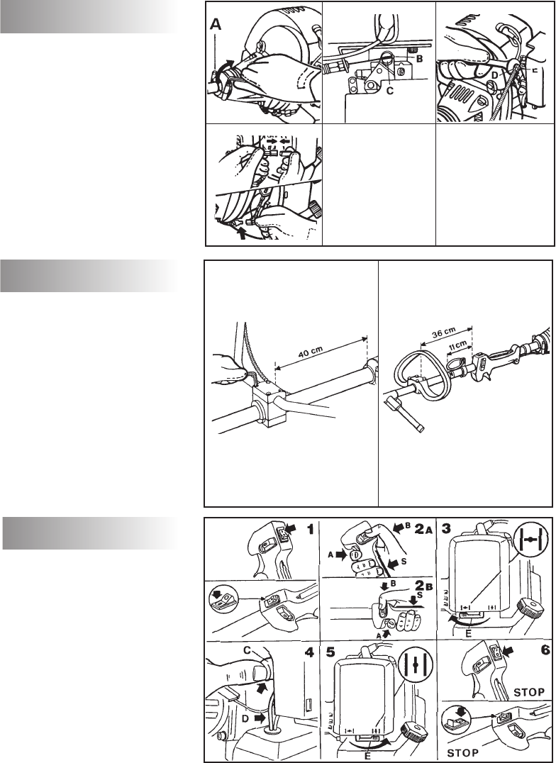
Legen Sie vor dem Gebrauch die Tragegurte
richtig an.Stellen Sie diese mit Hilfe der
Schnalle so ein, daß sich die Motorsense
rechts von Ihnen im Gleichgewicht und das
Schlagblatt bzw. der Fadenkopf parallel zum
Boden befindet. Verwenden Sie das Gerät
nicht bei instabiler Beinstellung; die Kontrolle
des Gleichgewichts ist unbedingte
Voraussetzung. Bewegen Sie sich niemals
rückwärts, da sie während des Arbeitens
Gegenstände und andere Gefahren hinter sich
nicht erkennen können. Bei Modellen mit
Deltagriff, für die der Gebrauch von
Schlagblättern vorgesehen ist, muß unbedingt
die seitlich absperrende Griffverlängerung
angebracht werden. Diese Griffverlängerung
soll ein übermäßiges Ausschlagen des Gerätes
verhindern und gewährleistet einen
Sicherheitsabstand zwischen Benutzer und
Metallblatt.
2) Der Tragering (B) muß in der Ausgangsstellung
verbleiben, um das Gleichgewicht des Gerätes
zu gewährleisten. Bei Modellen mit V-förmigen
Griff kann der vordere Halbgriff für einen
bequemeren Gebrauch getrennt eingestellt
werden.
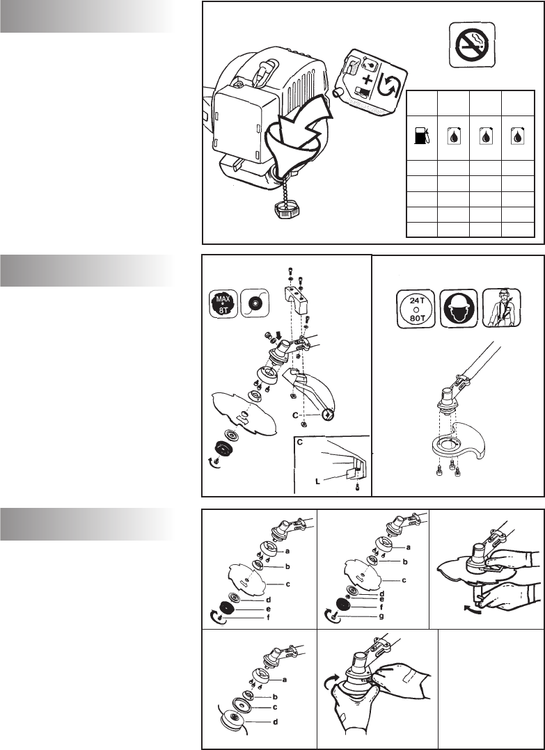
3) Für Ihre Motorsense stehen folgende
Zubehörteile zur Verfügung:
a) Schlagblatt, b) Nylonfadenkopf.
Montieren Sie kein Schlagblatt ohne den
korrekten Einbau aller vorgesehenen Teile.
Andernfalls könnte sich das Schlagblatt lösen
und den Benutzer bzw. andere Personen
verletzen.
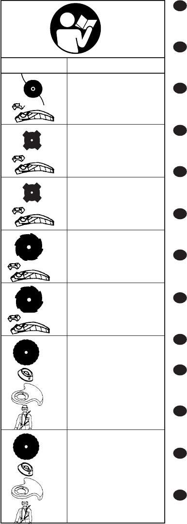
a) BEI VERWENDUNG EINES ROTIERENDEN
SCHLAGBLATTES MUSS UNBEDINGT DIE
ENTSPRECHENDE SCHUTZVORRICHTUNG
ANGEBAUT WERDEN.
b) BEI VERWENDUNG EINES FADENKOPFES
MUSS UNBEDINGT DIE ENTSPRECHENDE
SCHUTZVORRICHTUNG ANGEBAUT WERDEN.
Halten Sie den vorderen Teil des Gerätes
(Schlagblatt bzw. Fadenkopf) beim Gebrauch
unterhalb der Taille.
NYLONFADENKOPF:
Achten Sie darauf, daß dieser immer korrekt
montiert ist. Verwenden Sie ihn für die Schur
von Grasböden, zum Schneiden von Gras und
Unkraut an Rändern oder dort, wo Hindernisse
wie Bäume, Einzäunungen und Mauern
vorhanden sind. Der Nylonfadenkopf schränkt
außerdem Beschädigungen von Pflanzen und
Baumrinden ein. Verwenden Sie für die
Fadenköpfe ausschließlich vom Hersteller
empfohlene Fäden aus flexiblem Material und
niemals Metallfäden, die brechen und zu
gefährlichen Geschossen werden könnten
SCHLAGBLATT:
Achten Sie immer auf eine korrekte Montage.
Beachten Sie bei der Montage der
Schneidwerkzeuge genauestens die
Anweisungen im Kapitel MONTAGE VON
SCHLAGBLATT UND NYLONFADENKOPF.
arbeiten oder das Schlagblatt bzw. den
Fadenkopf berühren. Dies gilt besonders für
das Entfernen von festgesetztem Material.
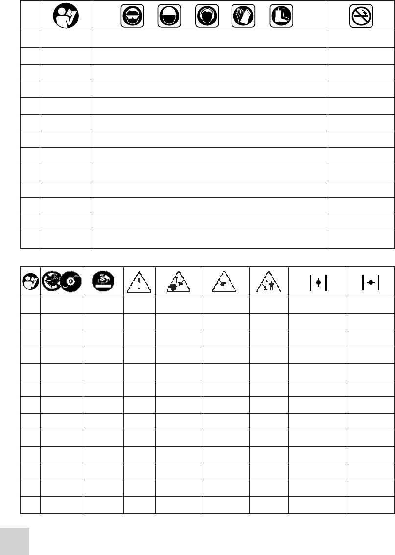
VERWENDEN SIE DIE MOTORSENSE AUF
KEINEN FALL OHNE DIE KORREKT
ANGEBRACHTE SCHUTZVORRICHTUNG (siehe
Kapitel SICHERER GEBRAUCH und MONTAGE
VON SCHLAGBLATT UND NYLONFADENKOPF).
Die Nichtbeachtung dieser Vorschriften kann zu
gefährlichen Situationen führen wie a) Kontakt mit
den rotierenden und scharfen Teilen,b)
Hochschleudern verschiedener Gegenstände.
ACHTUNG
Lassen Sie den Motor niemals getrennt vom
Tragrohr an, da sonst die Kupplung explodieren
könnte.Vergewissern Sie sich bei den Geräten mit
Kupplung, daß das Schneidwerkzeug bei
leerlaufendem Motor stillsteht.
C. SICHERER GEBRAUCH
25
1-30 cabrio 320-380-248729 29-11-2001 14:38 Pagina 25
Achten Sie beim Befestigen der
Schneidwerkzeuge darauf, daß alle
mitgelieferten Teile laut Beschreibung korrekt
und in der richtigen Reihenfolge montiert
werden.
4) SCHLAGBLÄTTER: Mit Hilfe der Schlagblätter
können alle Arten von Gras, Gestrüpp und
Sträuchern geschnitten werden. Bewegen Sie
das Gerät wie eine Sense. Schneiden Sie stets
mit bis zum Anschlag durchgezogenem
Gashebel.
5) ACHTUNG: Verwenden Sie nur gut geschärfte
Schlagblätter. Ein Schlagblatt mit abgenutzten
Zähnen bereitet nicht nur Schwierigkeiten beim
Schneiden, sondern kann darüber hinaus zu einem
RÜCKSTOSS, das heißt starkem Asschlagen des
Gerätes führen/ welches durch das Auftreffen des
Schlagblattes auf Holz oder andere feste
Gegenstände hervorgerufen wird. Dieser Stoß kann
sich vom Gerät auf den Benutzer übertragen und
zu einem Verlust der Kontrolle über das Gerät
führen. Arbeiten Sie daher nie mit beschädigtem
Schlagblatt, sondern tauschen Sie es aus.
RÜCKSTOSS: Dieser kann auch bei
Verwendung jeglicher Art von Kreissägeblättern
im gekennzeichneten Gefahrenbereich
auftreten. Schneiden Sie daher nur im
verbleibenden Bereich.
KREISSÄGEBLÄTTER: Sie eignen sich zum
Schneiden von Trieben und kleinen Bäumen
mit einem Durchmesser von bis zu 7 cm sowie
zur Säuberung von Sträuchern.
ACHTUNG: BEI VERWENDUNG EINES 24-
80 ZAHN METALLBLATTES MÜSSEN EIN
DOPPELTRAGEGURT UND DAS
ENTSPRECHENDE SCHUTZBLECH GEMÄß
DER ÜBERSICHTSTABELLE VERWENDET
WERDEN. (BEACHTEN SIE DIE
KLEIDUNGSVORSCHRIFT IM KAPITEL
SICHERHEIT: HELM TRAGEN.)
VERWENDEN SIE AUSSCHLIEßLICH DIE BEI
IHRER AUTORISIERTEN
KUNDENDIENSTSTELLE ERHÄLTLICHEN
ORIGINALZUBEHÖR- UND ERSATZTEILE. DIE
BENUTZUNG VON NICHT ORIGINALZUBEHÖR
UND -ERSATZTEILEN ERHÖHT DIE
UNFALLGEFAHR. IN DIESEM FALL
ÜBERNIMMT FÜR PERSONEN- ODER
SACHSCHÄDEN KEINE VERANTWORTUNG.
Verwenden Sie ausschließlich den im vorliegenden
Handbuch empfohlenen Kraftstoff.
Das Gerät ist mit einem Zweitaktmotor
ausgestattet und muß daher mit einem Benzin-
Ölgemisch betrieben werden. Verwenden bleifreies
Benzin mit mindestens 90 Oktan.
Kaufen Sie Öl nur in versiegelten Behältern. Die
beste Mischung erhalten Sie, wenn Sie zuerst das
Öl in einen geeigneten Kanister gießen und erst
anschließend das Benzin hinzufügen.
Die Verwendung von qualitativ minderwertigem
Benzin oder Öl kann zu verminderter
Leistungsfähigkeit führen oder auch die
Lebensdauer gewisser Kompenenten verkürzen.
BLEIFREIES BENZIN
Für eine geeignete Mischung mit bleifreiem Benzin
verwenden Sie vollkommen synthetisches 2-
Takter Öl oder 2-Takter Motorenöl, siehe Tabelle.
WICHTIG
Kanister mit Kraftstoffgemisch vor jedem
Gebrauch gut schütteln.
Zweitaktergemische zersetzen sich schnell und
sollten innerhalb von 2 Monaten aufgebraucht
werden.
Wir empfehlen daher, jeweils nur die
unmittelbar
benötigte Menge Kraftstoffgemisch
vorzubereiten.
Verwenden Sie niemals Mischungen, die älter als
2 Monate sind. Dies kann zu Motorschäden
führen.
ACHTUNG
Niemals während des Umgangs mit Kraftstoff
rauchen. Öffnen Sie den Tankdeckel immer
langsam, damit eventuell vorhandener Druck
entweichen kann. Niemals in geschlossenen
Räumen oder in der Nähe von Flammen oder
Funken auftanken.
SICHERHEIT BEIM UMGANG MIT
KRAFTSTOFF
Benzin ist leicht entflammbar. Vor dem Umgang
mit Benzin müssen alle offenen Flammen gelöscht
werden. Rauchen ist strengstens verboten.
Vermeiden Sie das Verschütten von Benzin.
Bewahren Sie den Brennstoff an einem gut
gelüfteten Ort in eigens dafür zugelassenen
Behältern auf. Lassen Sie Geräte niemals mit
gefülltem Tank in geschlossenen oder wenig
belüfteten Räumen, in denen die vom Benzin
produzierten Gase in den Bereich von
Feuerquellen oder Flammen von Brennern,
Heizungen, Boilem, Textiltrocknern usw. kommen
könnten.
Die von Brennstoffen entwickelten Dämpfe
können Explosionen oder Brände verursachen.
Bewahren Sie niemals große Mengen Kraftstoff
auf. Achten Sie darauf, den Tank niemals
vollkommen leer laufen zu lassen, um
Schwierigkeiten beim Wiederanlassen zu
vermeiden und die Lebensdauer des Motors zu
verlängern.
26
C
D. KRAFTSTOFFGEMISCH
1-30 cabrio 320-380-248729 29-11-2001 14:38 Pagina 26
31


Need help? Post your question in this forum.

Forumrules


Report abuse

Libble takes abuse of its services very seriously. We're committed to dealing with such abuse according to the laws in your country of residence. When you submit a report, we'll investigate it and take the appropriate action. We'll get back to you only if we require additional details or have more information to share.

Product:

For example, Anti-Semitic content, racist content, or material that could result in a violent physical act.

For example, a credit card number, a personal identification number, or an unlisted home address. Note that email addresses and full names are not considered private information.

Forumrules

To achieve meaningful questions, we apply the following rules:

Register

Register getting emails for McCulloch CABRIO 341 at:


You will receive an email to register for one or both of the options.


Get your user manual by e-mail

Enter your email address to receive the manual of McCulloch CABRIO 341 in the language / languages: English, German, Dutch, Danish, French, Italian, Portuguese, Swedish, Spanish, Norwegian, Finnish as an attachment in your email.

The manual is 1,52 mb in size.


You will receive the manual in your email within minutes. If you have not received an email, then probably have entered the wrong email address or your mailbox is too full. In addition, it may be that your ISP may have a maximum size for emails to receive.

Others manual(s) of McCulloch CABRIO 341

McCulloch CABRIO 341 User Manual - English - 13 pages


The manual is sent by email. Check your email

If you have not received an email with the manual within fifteen minutes, it may be that you have a entered a wrong email address or that your ISP has set a maximum size to receive email that is smaller than the size of the manual.

The email address you have provided is not correct.

Please check the email address and correct it.

Your question is posted on this page

Would you like to receive an email when new answers and questions are posted? Please enter your email address.


Info