28
Boren met de diamant kroonboor
LET OP:
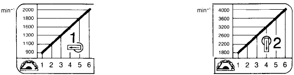
• Voor boren met de diamant kroonboor dient de
boorwerkingskeuzehendel altijd in de
S positie
voor “alleen boren” te worden gezet. Indien u de
diamant kroonboor gebruikt voor “hamerend boren”,
kan de diamant kroonboor beschadigd raken.
• Het boorvermogen en de gebruiksduur van de diamant
kroonboor hangen in grote mate af van het soort en de
toestand van het te boren materiaal. Over het
algemeen stompt hard materiaal de diamant kroonboor
sneller af en verkort zacht materiaal, zoals vers gestort
beton of betonblokken, de gebruiksduur van de
diamant kroonboor.
• Wanneer het boorvermogen van de diamant kroonboor
begint te verminderen, moet u de boor aanscherpen
met behulp van een oude, afgedankte slijpschijf met
grove korrels of een betonblok. Zet de slijpschijf of het
betonblok stevig vast en boor er in. Wanneer u een
stompe boor blijft gebruiken, kunnen de diamant
deeltjes afbreken of eraf vallen.
• Bij gebruik van een nat type diamant kroonboor, dient u
altijd de beveiligingskap (los verkrijgbaar) te installeren
om het gereedschap volledig te beschermen tegen
water. Zie de paragraaf “Installeren van de
beveiligingskap”.
• Na gebruik van een nat type diamant kroonboor, dient
u de boor in water af te wassen en deze vervolgens
samen met de spons en de geleidering in een droge
ruimte op te bergen.
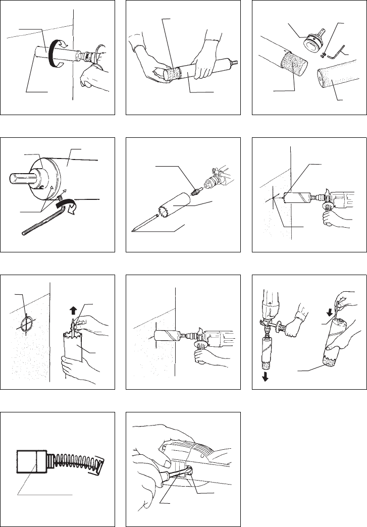
1. Boren met een nat type diamant kroonboor
Trek eerst de stekker van het gereedschap uit het
stopcontact. Dompel de spons in water. Houd het
gereedschap staande met de boor naar boven. Vul
de boor voorzichtig halfvol met water. Steek
vervolgens de spons, met de klinknagel naar boven,
voorzichtig en zo diep mogelijk in de boor. (Fig. 9)
LET OP:
Wees tijdens het vullen van de boorkop met water
dubbel voorzichtig dat het gereedschap niet nat
wordt.
Verwijder zonodig water en vuil van de geleidering
en van de plek waar geboord moet worden. Plak het
kleefblad op de plek en plaats hierop de geleidering.
(Fig. 10)
Plaats de boor in de geleidering en schakel het
gereedschap in. (Fig. 11)
Boor een geleidegroef, schakel het gereedschap uit
en verwijder de geleidering en het kleefblad.
(Fig. 12)
Plaats de boor in de geleidegroef en schakel het
gereedschap in. Draai het gereedschap langzaam in
het te boren gat terwijl u het schuins houdt onder
een hoek van 2° – 3°. Verminder geleidelijk de hoek
naarmate het gat dieper wordt. Vlak voordat de boor
aan de andere kant tevoorschijn komt, dient de boor
ten opzichte van het gat haaks te staan. Schakel het
gereedschap uit nadat het gat volledig is geboord.
Alvorens het gereedschap eruit te trekken, wacht
totdat de boor helemaal tot stilstand is gekomen
(Fig. 13)
LET OP:
Controleer of tijdens het boren het water regelmatig
uit het gat loopt. Indien het water niet goed eruit
loopt, trek dan het gereedschap even terug en druk
het er vervolgens weer in. Het water moet
onbelemmerd vloeien. Indien het probleem daarmee
niet is verholpen, schakel dan het gereedschap
onmiddellijk uit, trek de stekker uit het stopcontact
en vul de boor met water bij.
Wanneer u daarna het boren hervat, moet u eerst de
boor zo ver mogelijk in het gat steken en pas daarna
het gereedschap inschakelen.
Verwijder de vuilkern langs het voorste gat uit de
boor. (Fig. 14)
LET OP:
Probeer niet om de vuilkern met een haak e.d. uit de
boor te verwijderen of door met een
schroevendraaier enz. op de boor te kloppen.
Wanneer u de vuilkern niet langs het voorste gat
kunt verwijderen, maak dan de schroeven met de
inbussleutel los en verwijder de boorkophouder.
Verwijder vervolgens de spons en de vuilkern langs
het achterste gat. (Fig. 15)
Om de houder te installeren, breng de merktekens
op de houder en op de boor op één lijn en draai de
schroeven goed vast met de inbussleutel. (Fig. 16)
LET OP:
Pas op dat u de diamant kroonboor of de O-ring op
de houder niet beschadigt.
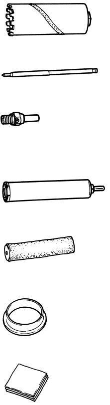
2. Boren met een droog type diamant kroonboor
Verwijder eerst de stekker van het gereedschap uit
het stopcontact. Zet de boorschacht, de kroonboor
en de centerboor ineen. Monteer vervolgens het
geheel op de boorkop. (Fig. 17)
Plaats de punt van de centerboor precies in het
middelpunt van het gat dat geboord moet worden.
Schakel het gereedschap in en boor in het beton
totdat het diamant gedeelte van de kroonboor een
diepte van 3 – 5 mm heeft bereikt. Dit is dan de
geleidegroef die het verder boren vergemakkelijkt.
(Fig. 18)
Verwijder de centerboor van de kroonboor en plaats
de kroonboor terug in de geleidegroef. Boor het gat
terwijl u de boor haaks tegen het beton houdt. Oefen
tijdens het boren geen overmatige druk op het
gereedschap uit. (Fig. 19)
Verminder de druk op het gereedschap wanneer de
kroonboor in contact komt met betonijzer e.d. en
wanneer de kroonboor aan de andere kant
tevoorschijn begint te komen. (Fig. 20)
Om de vuilkern uit de kroonboor te verwijderen,
moet u de kroonboor naar beneden richten. Indien
de vuilkern er niet soepel uitvalt, steek dan een
dunne staaf door het gaatje aan de achterkant van
de kroonboor om de vuilkern eruit te drukken.
(Fig. 21)
LET OP:
Wanneer u in vers gestort beton of naar beneden
boort, kan het zijn dat het gruis moeilijk uit het gat te
verwijderen is. Gebruik in dit geval een stofzuiger.