448241
10
Zoom out
Zoom in
Previous page
1/14
Next page
GB
Cordless Impact Wrench Instruction Manual
F
Boulonneuse sans fil Manuel d’instructions
D
Akku-Schlagschrauber Betriebsanleitung
I
Avvitatrice ad impulso a batteria Istruzioni per l’uso
NL
Snoerloze slagmoersleutel Gebruiksaanwijzing
E
Llave de impacto a batería Manual de instrucciones
P
Chave de impacto a bateria Manual de instruções
DK
Elektronisk akku slagnøgle Brugsanvisning
S
Sladdlös mutterdragare Bruksanvisning
N
Batteridrevet slagskrunøkkel Bruksanvisning
SF
Akku-iskuväännin Käyttöohje
GR Ασύρµατο κρουστικ κλειδί Οδηγίες χρήσεως
6991D
6992D
2
2
1
3
4
12
34
5
5
3
6
7
88
910
11 12
5
8. The proper fastening torque may differ depend-
ing upon the kind or size of the bolt. Check the
torque with a torque wrench.
SAVE THESE INSTRUCTIONS.
OPERATING INSTRUCTIONS
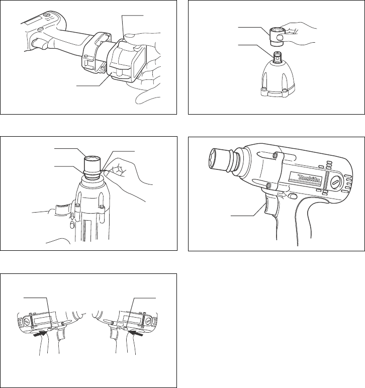
Installing or removing battery cartridge (Fig. 1)
Always switch off the tool before insertion or removal of
the battery cartridge.
• To remove the battery cartridge, withdraw it from the
tool while pressing the push buttons on both sides of
the cartridge.
To insert the battery cartridge, align the tongue on the
battery cartridge with the groove in the housing and slip
it into place. Always insert it all the way until it locks in
place with a little click. If not, it may accidentally fall out
of the tool, causing injury to you or someone around
you.
Do not use force when inserting the battery cartridge. If
the cartridge does not slide in easily, it is not being
inserted correctly.
Selecting correct socket
Always use the correct size socket for bolts and nuts. An
incorrect size socket will result in inaccurate and incon-
sistent fastening torque and/or damage to the bolt or nut.
Installing or removing socket (Fig. 2 & 3)
CAUTION:
Always be sure that the tool is switched off and the bat-
tery cartridge is removed before installing or removing
the socket.
1. For socket without O-ring and pin
(Model 6991D & 6992D)
To install the socket, push it onto the anvil of the tool
until it locks into place.
To remove the socket, simply pull it off.
2. For socket with O-ring and pin (Model 6992D)
Move the O-ring out of the groove in the socket and
remove the pin from the socket. Fit the socket onto
the anvil of the tool so that the hole in the socket is
aligned with the hole in the anvil. Insert the pin
through the hole in the socket and anvil. Then return
the O-ring to the original position in the socket
groove to retain the pin. To remove the socket, fol-
low the installation procedures in reverse.
Switch action (Fig. 4)
CAUTION:
Before inserting the battery cartridge into the tool, always
check to see that the switch trigger actuates properly and
returns to the “OFF” position when released.
To start the tool, simply pull the trigger. Tool speed is
increased by increasing pressure on the trigger. Release
the trigger to stop.
Reversing switch action (Fig. 5)
CAUTION:
Always check the direction of rotation before operation.
Use the reversing switch only after the tool comes to a
complete stop. Changing the direction of rotation
before the tool stops may damage the tool.
When not operating the tool, always set the reversing
switch lever to the neutral position.
This tool has a reversing switch to change the direction
of rotation. Depress the reversing switch lever from the A
side for clockwise rotation or from the B side for counter-
clockwise rotation. When the switch lever is in the neutral
position, the switch trigger cannot be pulled.
Operation (Fig. 6 & 7)
The proper fastening torque may differ depending upon
the kind or size of the bolt. The relation between fasten-
ing torque and fastening time is shown in the figures.
Hold the tool firmly and place the socket over the bolt or
nut. Turn the tool on and fasten for the proper fastening
time.
NOTE:
Hold the tool pointed straight at the bolt or nut without
applying excessive pressure on the tool.
Excessive fastening torque may damage the bolt or
nut. Before starting your job, always perform a test
operation to verify the adequate fastening speed and
time for your bolt or nut.
The fastening torque is affected by a wide variety of fac-
tors including the following. After fastening, always check
the torque with a torque wrench.
1. When the battery cartridge is discharged almost
completely, voltage will drop and the fastening
torque will be reduced.
2. Socket
Failure to use the correct size socket will cause a
reduction in the fastening torque.
A worn socket (wear on the hex end or square
end) will cause a reduction in the fastening torque.
3. Bolt
Even though the torque coefficient and the class of
bolt are the same, the proper fastening torque will
differ according to the diameter of the bolt.
Even though the diameters of bolts are the same,
the proper fastening torque will differ according to
the torque coefficient, the class of bolt and the bolt
length.
4. The use of the universal joint or the extension bar
somewhat reduces the fastening force of the impact
wrench. Compensate by fastening for a longer
period of time.
5. Type of materials to be fastened, the manner of
holding the tool and the tool speed will affect the
torque.
CAUTION:
If the tool is operated continuously until the battery car-
tridge has discharged, allow the tool to rest for
15 minutes before proceeding with a fresh battery.
MAINTENANCE
CAUTION:
Always be sure that the tool is switched off and the bat-
tery cartridge is removed before carrying out any work on
the tool.
Replacement of carbon brushes (Fig. 8 & 9)
Replace carbon brushes when they are worn down to the
limit mark. Both identical carbon brushes should be
replaced at the same time.
To maintain product safety and reliability, repairs, mainte-
nance or adjustment should be carried out by a Makita
Authorized Service Center.
6
ACCESSORIES
CAUTION:
These accessories or attachments are recommended
for use with your Makita tool specified in this manual.
The use of any other accessories or attachments might
present a risk of injury to persons. Only use accessory
or attachment for its stated purpose.
If you need any assistance for more details regarding
these accessories, ask your local Makita service center.
Socket (with pin and O-ring)
For Model 6992D
Extension bar (with pin and O-ring)
For Model 6992D
Universal joint (with pin and O-ring)
For Model 6992D
Bit adapter (with pin and O-ring)
For Model 6992D
•Screw bits
Various type of Makita genuine batteries and chargers
Plastic carrying case
Shoulder strap
16
NEDERLANDS
Verklaring van algemene gegevens
1Knop
2 Accu
3Sok
4Draaistuk
5Pen
6O-ring
7 Trekschakelaar
8 Omkeerschakelaar
9 A zijde
10 B zijde
11 Rechtsom
12 Linksom
13 Aantrektijd
14 Seconden
15 Juist aantrekkoppel voor
16 Aantrekkoppel
17 Limietstreep
18 Schroevendraaier
19 Borstelhouderdop
TECHNISCHE GEGEVENS
Model 6991D 6992D
Capaciteiten
Standaardbout .......................................................................... M8 – M14 M8 – M14
Trekvaste bout .......................................................................... M6 – M10 M6 – M10
Vierkant ....................................................................................... 9,5 mm 12,7 mm
Toerental onbelast (min
–1
) ........................................................... 0 – 2 300 0 2 300
Aantal slagen per minuut ............................................................. 0 – 3 000 0 3 000
Maximaal aantrekkoppel ............................................................. 100 N•m 100 N•m
Totale lengte ................................................................................ 168 mm 176 mm
Netto gewicht (accu inbegrepen) ................................................. 1,3 kg 1,4 kg
Nominale spanning ..................................................................... D.C. 9,6 V D.C. 9,6 V
In verband met ononderbroken research en ontwikke-
ling behouden wij ons het recht voor bovenstaande
technische gegevens te wijzigen zonder voorafgaande
kennisgeving.
Opmerking: De technische gegevens kunnen van land
tot land verschillen.
Doeleinden van gebruik
Dit gereedschap is bedoeld voor het vastdraaien van
bouten en moeren.
Veiligheidswenken
Volg veiligheidshalve de bijgevoegde veiligheidsvoor-
schriften nauwkeurig op.
BELANGRIJKE
VEILIGHEIDSVOORSCHRIFTEN VOOR
ACCULADER EN ACCU
1. Lees alle voorschriften en waarschuwingen op
(1) de acculader, (2) de accu, en (3) het product
waarvoor de accu wordt gebruikt, aandachtig
door alvorens de acculader in gebruik te nemen.
2. Neem de accu niet uit elkaar.
3. Als de gebruikstijd van een opgeladen accu aan-
zienlijk korter is geworden, moet u het gebruik
ervan onmiddellijk stopzetten. Voortgezet
gebruik kan oververhitting, brandwonden en
zelfs een ontploffing veroorzaken.
4. Als er elektrolyt in uw ogen is terechtgekomen,
spoel dan uw ogen met schoon water en roep
onmiddellijk de hulp van een dokter in. Elektrolyt
in de ogen kan blindheid veroorzaken.
5. Bedek de accuklemmen altijd met de accukap
wanneer u de accu niet gebruikt.
6. Voorkom kortsluiting van de accu:
(1) Raak de accuklemmen nooit aan met een
geleidend materiaal.
(2) Bewaar de accu niet in een bak waarin
andere metalen voorwerpen zoals spijkers,
munten e.d. worden bewaard.
(3) Stel de accu niet bloot aan water of regen.
Kortsluiting van de accu kan oorzaak zijn van
een grote stroomafgifte, oververhitting, brand-
wonden, en zelfs defecten.
7. Bewaar het gereedschap en de accu niet op
plaatsen waar de temperatuur kan oplopen tot
50°C of hoger.
8. Werp de accu nooit in het vuur, ook niet wanneer
hij zwaar beschadigd of volledig versleten is. De
accu kan namelijk ontploffen in het vuur.
9. Wees voorzichtig dat u de accu niet laat vallen
en hem niet blootstelt aan schokken of stoten.
BEWAAR DEZE VOORSCHRIFTEN.
Tips voor een maximale levensduur van de accu
1. Laad de accu op voordat hij volledig ontladen is.
Stop het gebruik van het gereedschap en laad de
accu op telkens wanneer u vaststelt dat het ver-
mogen van het gereedschap is afgenomen.
2. Laad een volledig opgeladen accu nooit opnieuw
op. Als u de accu te veel oplaadt, zal hij minder
lang meegaan.
3. Laad de accu op bij een kamertemperatuur tus-
sen 10°C en 40°C. Laat een warme accu afkoelen
alvorens hem op te laden.
4. Laad de nikkel-metaalhydride accu op telkens
wanneer u hem langer dan zes maanden niet
hebt gebruikt.
AANVULLENDE
VEILIGHEIDSVOORSCHRIFTEN VOOR HET
GEREEDSCHAP
1. Denk eraan dat dit gereedschap altijd gebruiks-
klaar is, aangezien het niet op een stopcontact
hoeft te worden aangesloten.
18
2. Sok
Het gebruik van een sok van de onjuiste maat zal
resulteren in een te laag aantrekkoppel.
Een versleten sok (slijtage op het zeskante of vier-
kante uiteinde) zal resulteren in een te laag aan-
trekkoppel.
3. Bout
Zelfs wanneer de koppelverhouding en de klasse
van de bout overeenkomen, kan door verschillen in
de diameter van de bouten het juiste aantrekkop-
pel per bout toch afwijken.
Ook al zijn de diameters van twee bouten gelijk,
dan kunnen er nog verschillen in het juiste aan-
trekkoppel van de twee bouten optreden ten
gevolge van verschillen in de koppelverhouding en
de klasse en lengte van de bouten.
4. Het aantrekkoppel is iets lager wanneer een kogel-
gewrichtverbinding of verlengstaaf wordt gebruikt. U
kunt dit verlies aan aantrekkoppel compenseren
door de aantrektijd te verlengen.
5. Het materiaal van de vast te draaien bout of moer,
de manier van vasthouden van het gereedschap en
het toerental hebben invloed op het aantrekkoppel.
LET OP:
Indien u het gereedschap zonder onderbreking gebruikt
totdat de accu is uitgeput, dient u het gereedschap
15 minuten te laten rusten alvorens met een verse accu
verder te werken.
ONDERHOUD
LET OP:
Controleer altijd of het gereedschap is uitgeschakeld en
de accu is losgekoppeld vooraleer onderhoud uit te voe-
ren aan het gereedschap.
Vervangen van koolborstels (Fig. 8 en 9)
Vervang de borstels wanneer ze tot aan de aangegeven
limiet zijn afgesleten. Beide koolborstels dienen tegelij-
kertijd te worden vervangen.
Opdat het gereedschap veilig en betrouwbaar blijft, die-
nen alle reparaties, onderhoud of afstellingen te worden
uitgevoerd bij een erkend Makita service centrum.
ACCESSOIRES
LET OP:
• Deze accessoires of hulpstukken worden aanbevolen
voor gebruik met het Makita gereedschap dat in deze
gebruiksaanwijzing is beschreven. Bij gebruik van
andere accessoires of hulpstukken bestaat er gevaar
voor persoonlijke verwonding. Gebruik de accessoires
of hulpstukken uitsluitend voor hun bestemde doel.
Raadpleeg het dichtstbijzijnde Makita Servicecentrum
voor verder advies of bijzonderheden omtrent deze
accessoires.
Sok (met pen en O-ring)
Voor Model 6992D
Verlengstaaf (met pen en O-ring)
Voor Model 6992D
Aantrekkoppel (met pen en O-ring)
Voor Model 6992D
Bitadapter (met pen en O-ring)
Voor Model 6992D
•Schroefbits
Diverse types originele Makita accu’s en acculaders
Plastic draagkoffer
Schouderriem
40
ENH002-1
EC-DECLARATION OF CONFORMITY
We declare under our sole responsibility that this product is in com-
pliance with the following standards of standardized documents,
EN50260, EN55014
in accordance with Council Directives, 89/336/EEC and 98/37/EC.
DÉCLARATION DE CONFORMITÉ CE
Nous déclarons sous notre entière responsabilité que ce produit
est conforme aux normes des documents standardisés suivants,
EN50260, EN55014
conformément aux Directives du Conseil, 89/336/CEE et
98/37/EG.
CE-KONFORMITÄTSERKLÄRUNG
Hiermit erklärt wir unter unserer alleinigen Verantwortung, daß
dieses Produkt gemäß den Ratsdirektiven 89/336/EWG und 98/37/
EG mit den folgenden Normen von Normendokumenten überein-
stimmen:
EN50260, EN55014.
DICHIARAZIONE DI CONFORMITÀ
CON LE NORME DELLA COMUNITÀ EUROPEA
Dichiariamo sotto la nostra sola responsabilità che questo prodotto
è conforme agli standard di documenti standardizzati seguenti:
EN50260, EN55014
secondo le direttive del Consiglio 89/336/CEE e 98/37/CE.
EG-VERKLARING VAN CONFORMITEIT
Wij verklaren hierbij uitsluitend op eigen verantwoordelijkheid dat
dit produkt voldoet aan de volgende normen van genormaliseerde
documenten,
EN50260, EN55014
in overeenstemming met de richtlijnen van de Raad 89/336/EEC
en 98/37/EC.
DECLARACIÓN DE CONFORMIDAD DE LA CE
Declaramos bajo nuestra sola responsabilidad que este producto
cumple con las siguientes normas de documentos normalizados,
EN50260, EN55014
de acuerdo con las directivas comunitarias, 89/336/EEC y
98/37/CE.
DECLARAÇÃO DE CONFORMIDADE DA CE
Declaramos sob inteira responsabilidade que este produto obe-
dece às seguintes normas de documentos normalizados,
EN50260, EN55014
de acordo com as directivas 89/336/CEE e 98/37/CE do Con-
selho.
EU-DEKLARATION OM KONFORMITET
Vi erklærer hermed på eget ansvar, at dette produkt er i overens-
stemmelse med de følgende standarder i de normsættende doku-
menter,
EN50260, EN55014
i overensstemmelse med Rådets Direktiver 89/336/EEC og
98/37/EC.
EG-DEKLARATION OM ÖVERENSSTÄMMELSE
Under eget ansvar deklarerar vi härmed att denna produkt över-
ensstämmer med följande standardiseringar för standardiserade
dokument,
EN50260, EN55014
i enlighet med EG-direktiven 89/336/EEC och 98/37/EC.
EUs SAMSVARS-ERKLÆRING
Vi
erklærer
eget ansvar at dette produktet er i overensstem-
melse med følgende standard i de standardiserte dokumenter:
EN50260, EN55014,
i samsvar med Råds-direktivene, 89/336/EEC og 98/37/EC.
VAKUUTUS EC-VASTAAVUUDESTA
Yksinomaisesti vastuullisina ilmoitamme, että tämä tuote on
seuraavien standardoitujen dokumenttien standardien mukainen,
EN50260, EN55014
neuvoston direktiivien 89/336/EEC ja 98/37/EC mukaisesti.
∆ΗΛΩΣΗ ΣΥΜΜΟΡΦΩΣΗΣ ΕΚ
∆ηλώνουµε υπ την µοναδική µας ευθύνη τι αυτ το προιν
βρίσκεται σε Συµφωνία µε τα ακλουθα πρτυπα
τυποποιηµένων εγγράφων,
EN50260, EN55014
σύµφωνα µε τις Οδηγίες του Συµβουλίου, 89/336/EEC και
98/37/ΚE.
Yasuhiko Kanzaki
CE 2003
Director Director
Directeur Direktør
Direktor Direktör
Amministratore Direktor
Directeur Johtaja
Director ∆ιευθυντής
MAKITA INTERNATIONAL EUROPE LTD.
Michigan Drive, Tongwell, Milton Keynes,
Bucks MK15 8JD, ENGLAND
ENGLISH
FRANÇAISE
DEUTSCH
ITALIANO
NEDERLANDS
ESPAÑOL
PORTUGUÊS
DANSK
SVENSKA
NORSK
SUOMI
ΕΛΛΗΝΙΚΑ
41
Noise and Vibration of Model 6991D
The typical A-weighted noise levels are
sound pressure level: 97 dB (A)
sound power level: 110 dB (A)
– Wear ear protection. –
The typical weighted root mean square acceleration
value is 13 m/s
2
.
Bruit et vibrations du modèle 6991D
Les niveaux de bruit pondérés A types sont:
niveau de pression sonore: 97 dB (A)
niveau de puissance du son: 110 dB (A)
– Porter des protecteurs anti-bruit. –
L’accélération pondérée est de 13 m/s
2
.
Geräusch- und Vibrationsentwicklung
des Modells 6991D
Die typischen A-bewerteten Geräuschpegel betragen:
Schalldruckpegel: 97 dB (A)
Schalleistungspegel: 110 dB (A)
– Gehörschutz tragen. –
Der gewichtete Effektivwert der Beschleunigung beträgt
13 m/s
2
.
Rumore e vibrazione del modello 6991D
I livelli del rumore pesati secondo la curva A sono:
Livello pressione sonora: 97 dB (A)
Livello potenza sonora: 110 dB (A)
– Indossare i paraorecchi.
Il valore quadratico medio di accellerazione è di 13 m/s
2
.
Geluidsniveau en trilling van het model 6991D
De typische A-gewogen geluidsniveau’s zijn
geluidsdrukniveau: 97 dB (A)
geluidsenergie-niveau: 110 dB (A)
– Draag oorbeschermers. –
De typische gewogen effectieve versnellingswaarde is
13 m/s
2
.
Ruido y vibración del modelo 6991D
Los niveles típicos de ruido ponderados A son
presión sonora: 97 dB (A)
nivel de potencia sonora: 110 dB (A)
– Póngase protectores en los oídos. –
El valor ponderado de la aceleración es de 13 m/s
2
.
Ruído e vibração do modelo 6991D
Os níveis normais de ruído A são
nível de pressão de som: 97 dB (A)
nível do sum: 110 dB (A)
– Utilize protectores para os ouvidos –
O valor médio da aceleração é 13 m/s
2
.
Lyd og vibration fra model 6991D
De typiske A-vægtede lydniveauer er
lydtryksniveau: 97 dB (A)
lydeffektniveau: 110 dB (A)
– Bær høreværn. –
Den vægtede effektive accelerationsværdi er 13 m/s
2
.
Buller och vibration hos modell 6991D
De typiska A-vägda bullernivåerna är
ljudtrycksnivå: 97 dB (A)
ljudeffektnivå: 110 dB (A)
– Använd hörselskydd –
Det typiskt vägda effektivvärdet för acceleration är
13 m/s
2
.
Støy og vibrasjon fra modell 6991D
De vanlige A-belastede støynivå er
lydtrykksnivå: 97 dB (A)
lydstyrkenivå: 110 dB (A)
– Benytt hørselvern. –
Den vanlig belastede effektiv-verdi for akselerasjon er
13 m/s
2
.
Mallin 6991D melutaso ja tärinä
Tyypilliset A-painotetut melutasot ovat
äänenpainetaso: 97 dB (A)
äänen tehotaso: 110 dB (A)
– Käytä kuulosuojaimia. –
Tyypillinen kiihtyvyyden painotettu tehollisarvo on
13 m/s
2
.
Θρυβος και κραδασµς του µοντέλου 6991D
Οι τυπικές A-µετρούµενες εντάσεις ήχου είναι
πίεση ήχου: 97 dB (A)
δύναµη του ήχου: 110 dB (A)
– Φοράτε ωτοασπίδες. –
Η τυπική αξία της µετρούµενης ρίζας του µέσου
τετραγώνου της επιτάχυνσης είναι 13 m/s
2
.
ENGLISH
FRANÇAISE
DEUTSCH
ITALIANO
NEDERLANDS
ESPAÑOL
PORTUGUÊS
DANSK
SVENSKA
NORSK
SUOMI
ΕΛΛΗΝΙΚΑ
10


Need help? Post your question in this forum.

Forumrules


Report abuse

Libble takes abuse of its services very seriously. We're committed to dealing with such abuse according to the laws in your country of residence. When you submit a report, we'll investigate it and take the appropriate action. We'll get back to you only if we require additional details or have more information to share.

Product:

For example, Anti-Semitic content, racist content, or material that could result in a violent physical act.

For example, a credit card number, a personal identification number, or an unlisted home address. Note that email addresses and full names are not considered private information.

Forumrules

To achieve meaningful questions, we apply the following rules:

Register

Register getting emails for Makita 6992D at:


You will receive an email to register for one or both of the options.


Get your user manual by e-mail

Enter your email address to receive the manual of Makita 6992D in the language / languages: English, German, Dutch, Danish, French, Italian, Portuguese, Swedish, Spanish, Norwegian, Finnish as an attachment in your email.

The manual is 0,58 mb in size.


You will receive the manual in your email within minutes. If you have not received an email, then probably have entered the wrong email address or your mailbox is too full. In addition, it may be that your ISP may have a maximum size for emails to receive.

The manual is sent by email. Check your email

If you have not received an email with the manual within fifteen minutes, it may be that you have a entered a wrong email address or that your ISP has set a maximum size to receive email that is smaller than the size of the manual.

The email address you have provided is not correct.

Please check the email address and correct it.

Your question is posted on this page

Would you like to receive an email when new answers and questions are posted? Please enter your email address.


Info