REGOLAZIONI E SELETTORI.......................................................................................................................27
DATI TECNICI.................................................................................................................................................28
AJUSTES Y SELECTORES............................................................................................................................33
DATOS TECNICOS.........................................................................................................................................34
2
CONTENTS / INHALT / TABLE DE MATIERES /
INDICE / ìNDICE
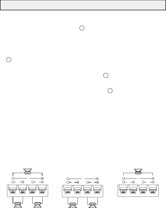
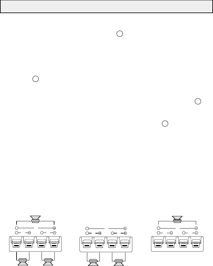
INSTALLATION / EINBAU / INSTALLATION /
INSTALLAZIONE / INSTALACION
4
Fig. 3/Abb. 3
5
INTRODUCTION
For us at MACROM the achievement of the topmost sound quality is one of our greatest
concerns. In buying one of the MACROM state-of-the-art amplifiers 43.05/43.07/43.10 we realize
that this is also your concern.
This unit offers 2x70/100/130 Watt max. per channel at 4 Ohm or 1x220/340/470 Watt max. when
mono-bridged with pure and stable sound qualities. This instruction manual has been realized to
help you to get the maximum out of the outstanding performances and the advanced features and
functions of your new power amplifier.
We advise you to read the following instructions very carefully in order to get familiar with the
outstanding performances and the advanced features and functions of your new unit 43.05/43.07/
43.10. Please report any problem to the nearest MACROM dealer.
PRECAUTIONS
1.The unit may be damaged by wrong lead connection, therefore read carefully the instructions
of this manual for the correct connection of the leads.
2.The last lead to be connected is the one to the positive (+) terminal of the battery; connect this
lead only after having completed and checked all other connections.
3.Due to the power of the 43.-series it is imperative that all connections are clean and secure in
order to avoid damage to the unit.
4.Be sure to install the amplifier in a position with good air circulation and good heat dissipation.
5.In case of fuse replacement make sure to replace them with fuses of the same amperage. The
use of fuses with the wrong amperage may seriously damage the components of the unit.
If fuses blow more than once, carefully check all electrical connections. Also have your car’s
voltage regulator checked. Do not attempt to repair the unit yourself.If repairs are ever needed,
take the unit to your MACROM dealer or to your nearest MACROM service station.
6.In order to obtain the best possible performance from this unit, make sure that the temperature
inside your car is within the range of -10° C and +60° C before you switch the unit on. Good air
circulation is essential to prevent heat build-up inside the unit.
6
FEATURES
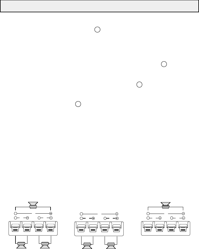
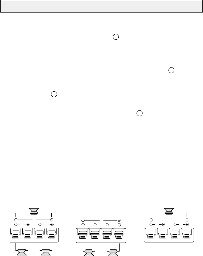
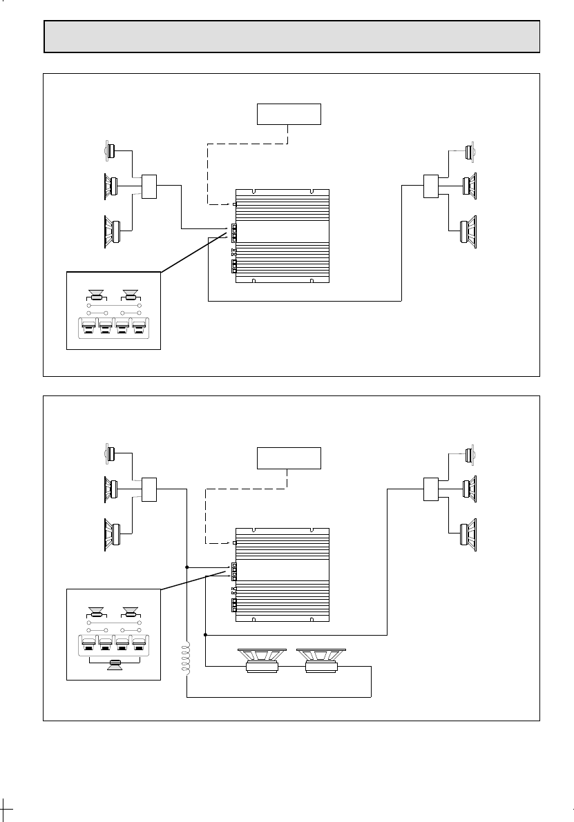
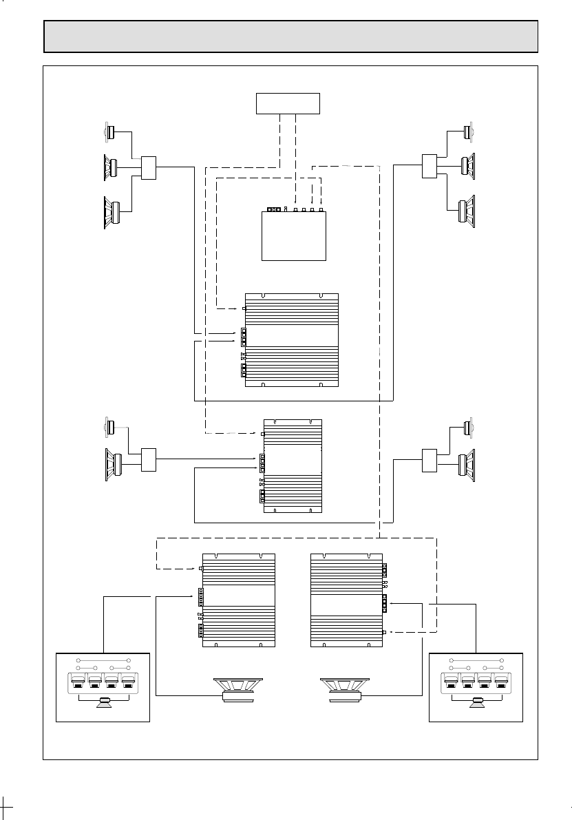
•3/2/1 CHANNEL OPERATION
The amplifier can be operated as a stereo or a as mono-bridged amplifier thus doubling the
output power independently from the input mode; the power can be subdivided as follows,
according to your needs:
a) 50/70/100 W RMS for each one of the two channels
b) 50/70/100 W RMS for two stereo channels, and 130/180/250 W RMS mono
c) 130/180/250 W RMS for one mono channel
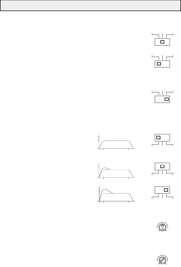
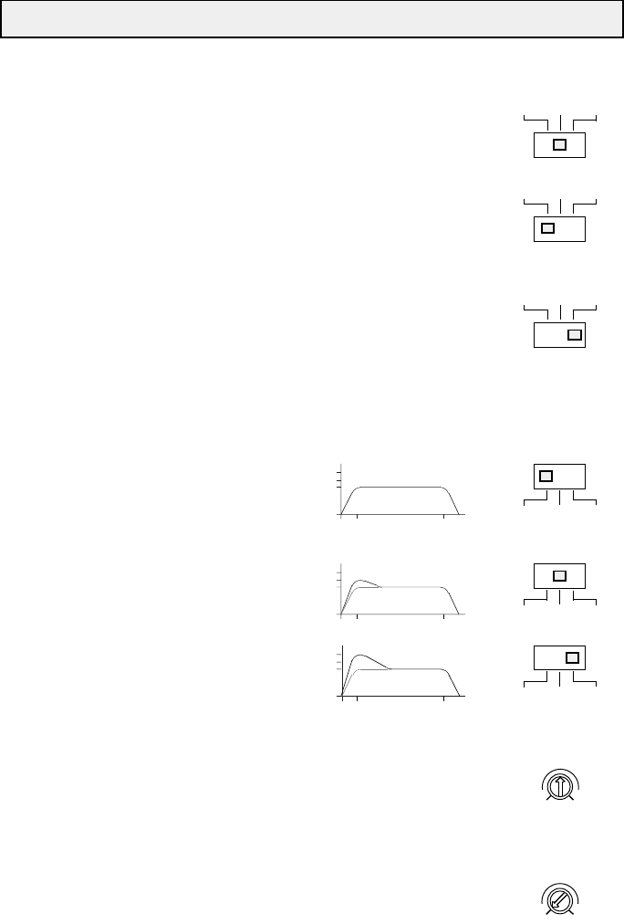
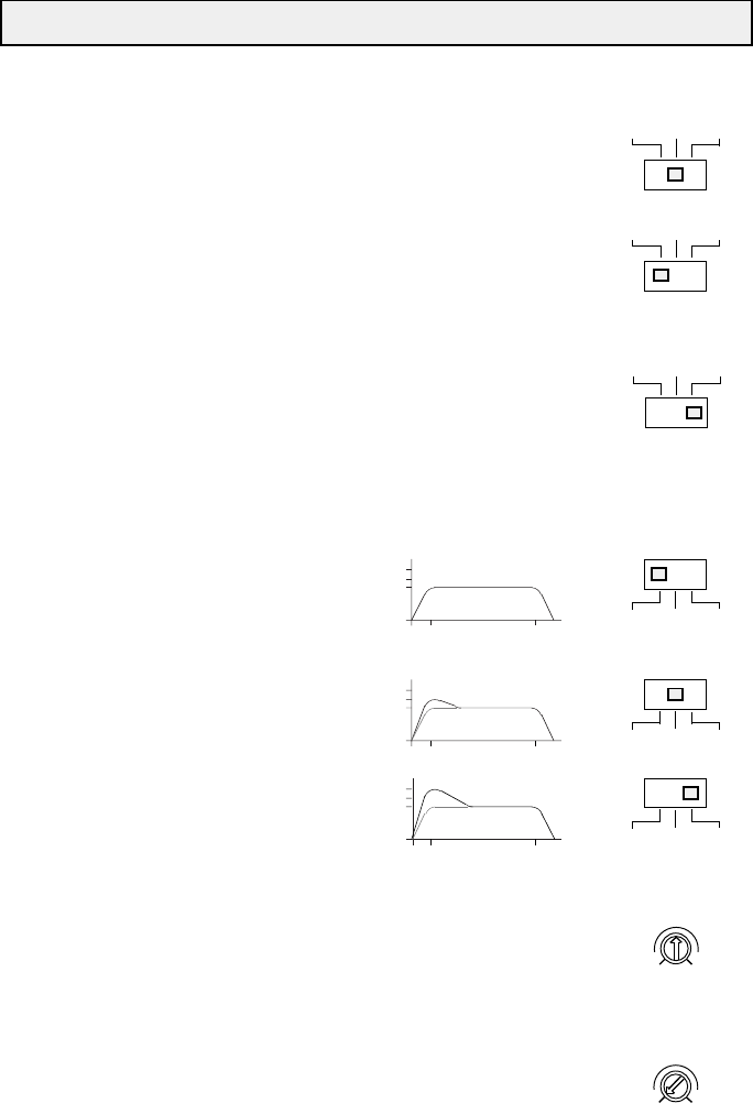
•LOW-BOOST SELECTOR
This switch boosts the low frequencies from 0 to +3 or +6 dB per octave.
•RCA INPUT SENSITIVITY
The new amplifier has an input sensitivity set to 500 mV for optimum coupling with other
MACROM sources. However, it is possible to adjust the sensitivity between 100 mV and 2 V for
easy coupling of other sources available on the market.
•CHECK CONTROL INDICATOR
This LED shows the current state of the amplifier.
WHITE The unit is switched off.
GREEN The unit works perfectly well.
RED The unit is in the protection mode, something is wrong.
•OPTICAL GROUND DECOUPLING SYSTEM WITH FOURFOLD PROTECTION
Your unit is equipped with four different protection devices, as befits all high-end products.
These protections are fitted with an optical decoupling system for the separation of the input
ground from the output ground:
SOFT START: the amp powers gradually in order to avoid damage to the speakers in case the
head unit is switched on with the volume control set to maximum.
OVERHEATING: in case of wrong installation the unit enters the protection mode before being
damaged. As soon as the temperature returns to normal values, the unit resumes normal
operation.
OVERLOADS: in case a series of speakers is connected to the amplifier with the total
impedance value dropping below a tolerable level of 1-1.5 Ohm, the unit enters the protection
mode. In this event check the total impedance value of the system.
OUTPUT SHORT CIRCUIT: in case of a short circuit at the speaker outlets the unit enters the
protection mode in order to avoid serious damage to the end-stage transistors. Normal
operation is resumed on eliminating the short circuit.
•CLASS-A DRIVER CIRCUIT
•END STAGE WITH DISCRETE COMPONENTS (TRANSISTORS)
•PWM MOS-FET POWER SUPPLY
The great power of the 43.-series is obtained by means of a special stabilized C-Mos-Fet PWM
(Pulse width modulation) supply unit which offers a constant power supply from 11 to 15 V, high
efficiency with low current draw, high power stability to sudden voltage changes in your car’s
electric system. The results are excellent performance, a linear and wide frequency response
with high dynamics.
•REMOTE ON AND OFF
On switching the head unit on or off, the amplifier is automatically switched on or off.
•CAPACITIVE/INDUCTIVE POWER SUPPLY FILTER
A special circuit assures low level of radio frequency interferences (RFI) and cuts off system
Libble takes abuse of its services very seriously. We're committed to dealing with such abuse according to the laws in your country of residence. When you submit a report, we'll investigate it and take the appropriate action. We'll get back to you only if we require additional details or have more information to share.
Product:
Forumrules
To achieve meaningful questions, we apply the following rules:
First, read the manual;
Check if your question has been asked previously;
Try to ask your question as clearly as possible;
Did you already try to solve the problem? Please mention this;
Is your problem solved by a visitor then let him/her know in this forum;
To give a response to a question or answer, do not use this form but click on the button 'reply to this question';
Your question will be posted here and emailed to our subscribers. Therefore, avoid filling in personal details.
Register
Register getting emails for Macrom 43.07 at:
new questions and answers
new manuals
You will receive an email to register for one or both of the options.
Get your user manual by e-mail
Enter your email address to receive the manual of Macrom 43.07 in the language / languages: English, German, French, Italian, Spanish as an attachment in your email.
The manual is 0,3 mb in size.
You will receive the manual in your email within minutes. If you have not received an email, then probably have entered the wrong email address or your mailbox is too full. In addition, it may be that your ISP may have a maximum size for emails to receive.
The manual is sent by email. Check your email
If you have not received an email with the manual within fifteen minutes, it may be that you have a entered a wrong email address or that your ISP has set a maximum size to receive email that is smaller than the size of the manual.
The email address you have provided is not correct.
Please check the email address and correct it.
Your question is posted on this page
Would you like to receive an email when new answers and questions are posted? Please enter your email address.