•SYSTEM CHART / SYSTEM-DIAGRAMM / EXEMPLES DE SYSTEME / DIAGRAMMA DI SISTEMA /
DIAGRAMA DEL SISTEMA...................................................................................................................................................5-6
CONTROLS AND INDICATORS....................................................................................................................................................9
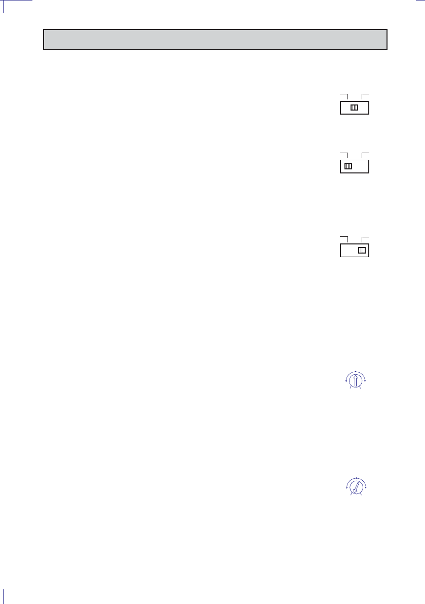
REGULATION AND SWITCH.....................................................................................................................................................11
STEUERUNGEN UND ANZEIGEN...............................................................................................................................................15
EINSTELLUNGEN UND SCHALTUNG........................................................................................................................................17
CONTROLES ET INDICATEURS .................................................................................................................................................21
REGAGES ET COMMUTATEUR..................................................................................................................................................23
CONTROLLI ED INDICATORI.....................................................................................................................................................27
REGOLAZIONI ED INTERRUTTORE...........................................................................................................................................29
DATI TECNICI ..............................................................................................................................................................................30
CONTROLES E INDICATORES ...................................................................................................................................................33
REGULACIONES E INTERRIPTORES ........................................................................................................................................35
DATOS TECNICOS......................................................................................................................................................................36
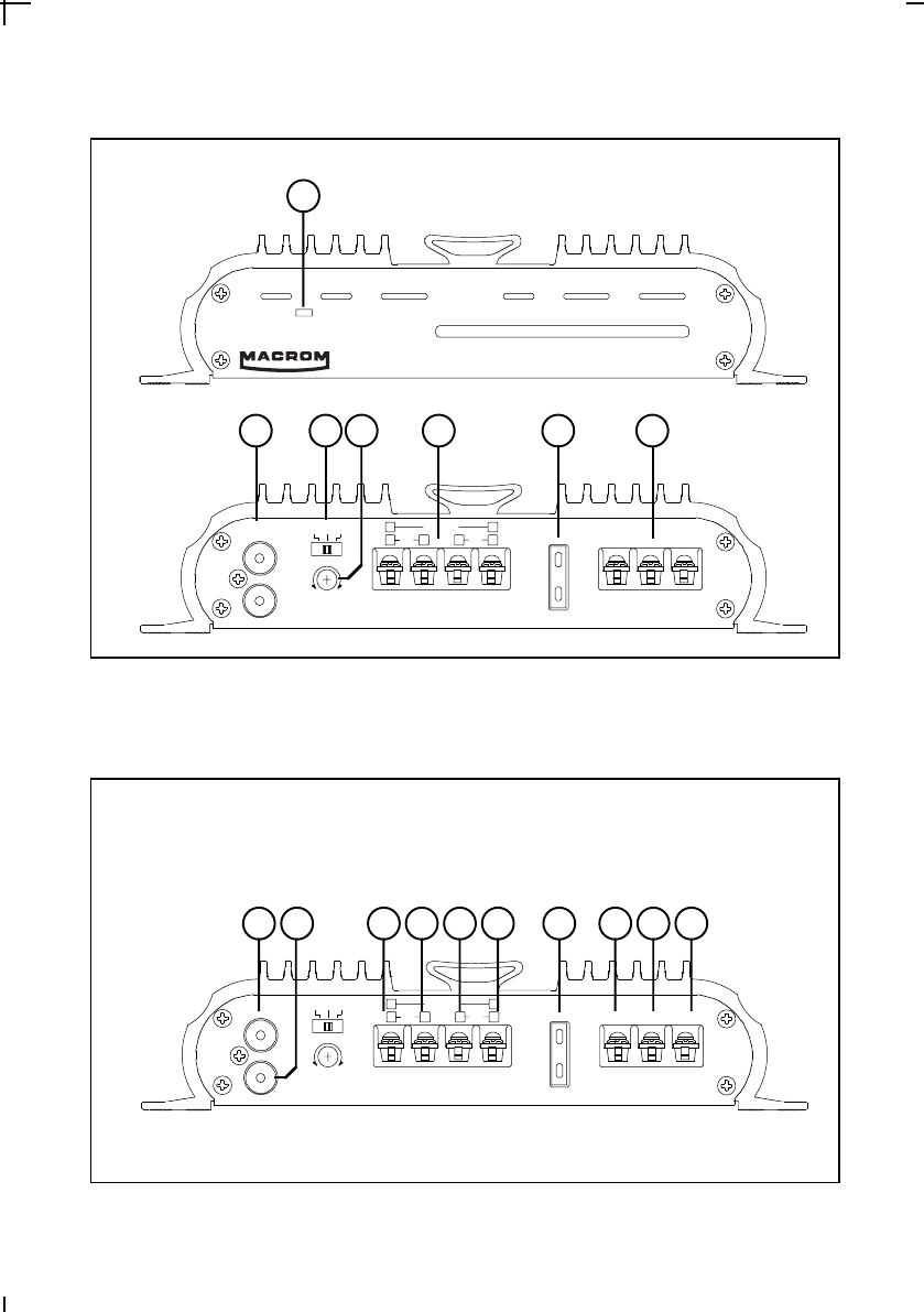
Fig. 2./ Abb. 2.
CONTROLS AND INDICATORS / BEDIENUNGSELEMENTE UND ANZEIGEN
COMMANDES ET INDICATEURS / COMANDI ED INDICATORI / CONTROLES E INDICATORES
4
L
R
L(mono)ST L+R
Gain Contr ol
2V0,1V
0,5V
R
-
++
Br idged
L
-
+ BattGNDRemo
te
-
+
Input
Fuse
20A
ChecK Control
Power Amplifier
1
2
L
R
L(mono)ST L+R
Gain Contr ol
2V0,1V
0,5V
R
-
++
Br idged
L
-
+ BattGNDRemot
e
-
+
Input
Fuse
20A
34567
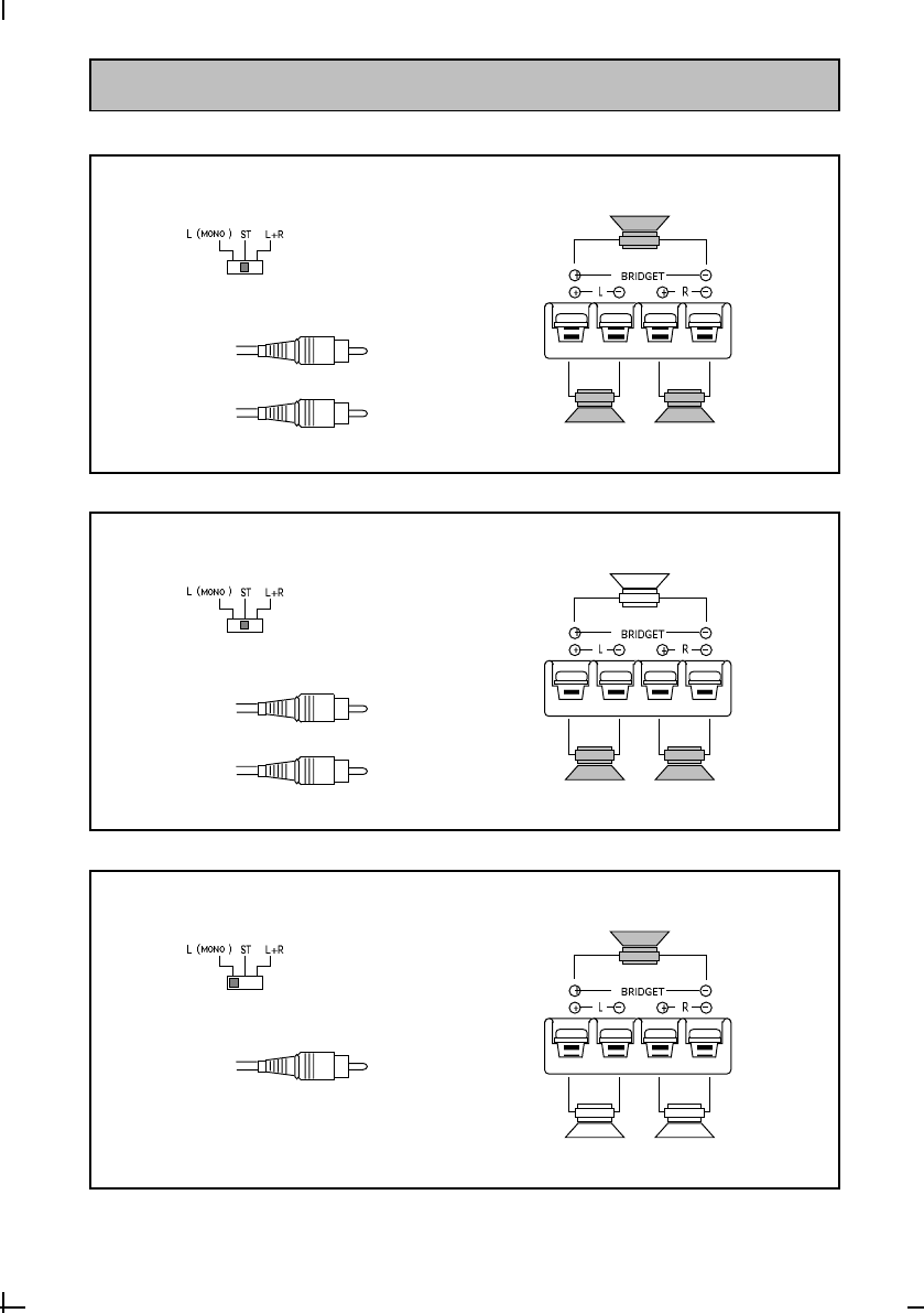
CONNECTIONS / ANSCHLUSSE / CONNEXIONS
COLLEGAMENTI / CONEXIONES
5
Fig. 3./ Abb. 3.
6123478910
3-CHANNEL CONFIGURATION
Left channel
Right channel
2-CHANNEL CONFIGURATION
Left channel
Right channel
1-CHANNEL CONFIGURATION
Left channel
LeftRight
Mono
LeftRight
Mono
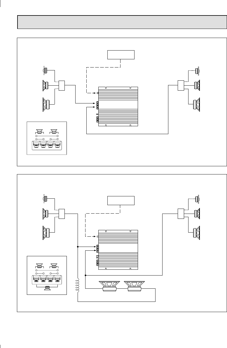
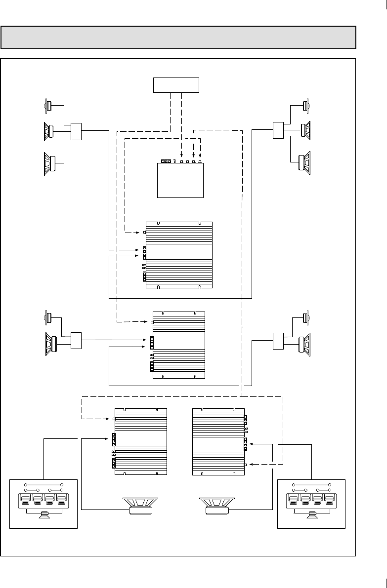
SYSTEM DIAGRAM / SYSTEM-DIAGRAMM / EXEMPLES DE SYSTEME
DIAGRAMMA DI SISTEMA / DIAGRAMA DEL SISTEMA
Note: For the other channel
another amplifier must to be
used in same way.
5
Three channel passive configuration
38
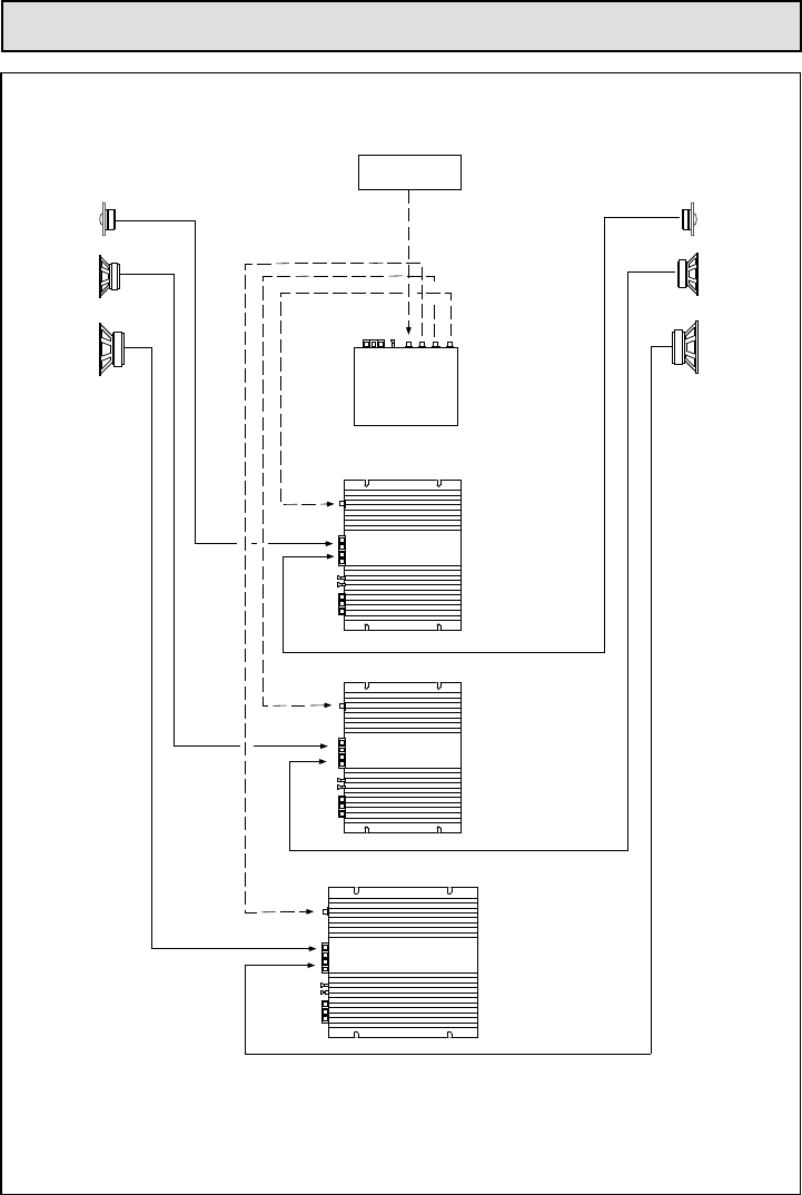
SYSTEM CHART / SYSTEM-DIAGRAMM / EXEMPLES DE SYSTEME
DIAGRAMMA DI SISTEMA / DIAGRAMA DEL SISTEMA
59.16
59.10
57.00
59.16
59.10
57.00
95.8395.83
59.25
59.25
Audio Signal
+
-
+
-
-
+
MONO
Audio Signal
Two channel configuration
59.16
59.10
57.00
59.16
59.10
57.00
95.8395.83
Power Amplifier
42.24 - 42.26
Coil 5mH
LEFTRIGHT
+
-
+
-
-
+
LEFTRIGHT
Power Amplifier
42.24 - 42.26
MACROM INGLESE 42.15 - 42.17 17 FEBBRAIO 19937
PRECAUTIONS
1.The unit may be damaged by wrong lead connection, therefore read carefully the instructions
of this manual for the correct connection of the leads.
2.The last lead to be connected is the one to the positive (+) terminal of the battery; connect this
lead only after having completed and checked all other connections.
3.Due to the power of the 42.24/42.26 it is imperative that all connections are clean and secure
in order to avoid damage to the unit.
4.Be sure to install the amplifier in a position with good air circulation and good heat dissipation.
5.In case of fuse replacement make sure to use fuses of the same amperage.
The use of fuses with the wrong amperage may seriously damage the components of the unit.
If fuses blow more than once, carefully check all electrical connections. Also have your car’s
voltage regulator checked. Do not attempt to repair the unit yourself. If repairs are ever needed,
take the unit to your MACROM dealer or to your nearest MACROM service station.
6.In order to obtain the best possible performance from this unit, make sure that the temperature
inside your car is within the range of -10°C and +60°C before you switch the unit on. Good air
circulation is essential to prevent heat build-up inside the unit.
INTRODUCTION
For us at MACROM the achievement of the best sound quality is one of our greatest concerns. In
buying the Digital Ready amplifier MACROM 42.24/42.26 we realize that this is also your concern.
This unit offers 60/80 Watt max. per channel at 4 Ohm or 125/156 Watt max. when mono-bridged
with pure and stable sound qualities.
This instruction manual has been prepared in order to help you to make the most of the outstanding
performances and the advanced features and functions of your new amp.
We advise you to read these instructions carefully to famialirise yourself with all the special feature
of your 42.24/42.26
Please report any problem to your nearest MACROM dealer.
7
MACROM INGLESE 42.15 - 42.17 17 FEBBRAIO 19938
FEATURES
•3/2/1 CHANNEL OPERATION
The amplifier can be operated as a stereo or a as mono-bridged amplifier thus doubling the output
power independently from the input mode; the power can be subdivided as follows, according to
your needs:
a) 60/80 Watts for each one of the two channels
b) 60/80 Watts for two stereo channels, and 125/156 Watts mono
c) 125/156 Watts for one mono channel
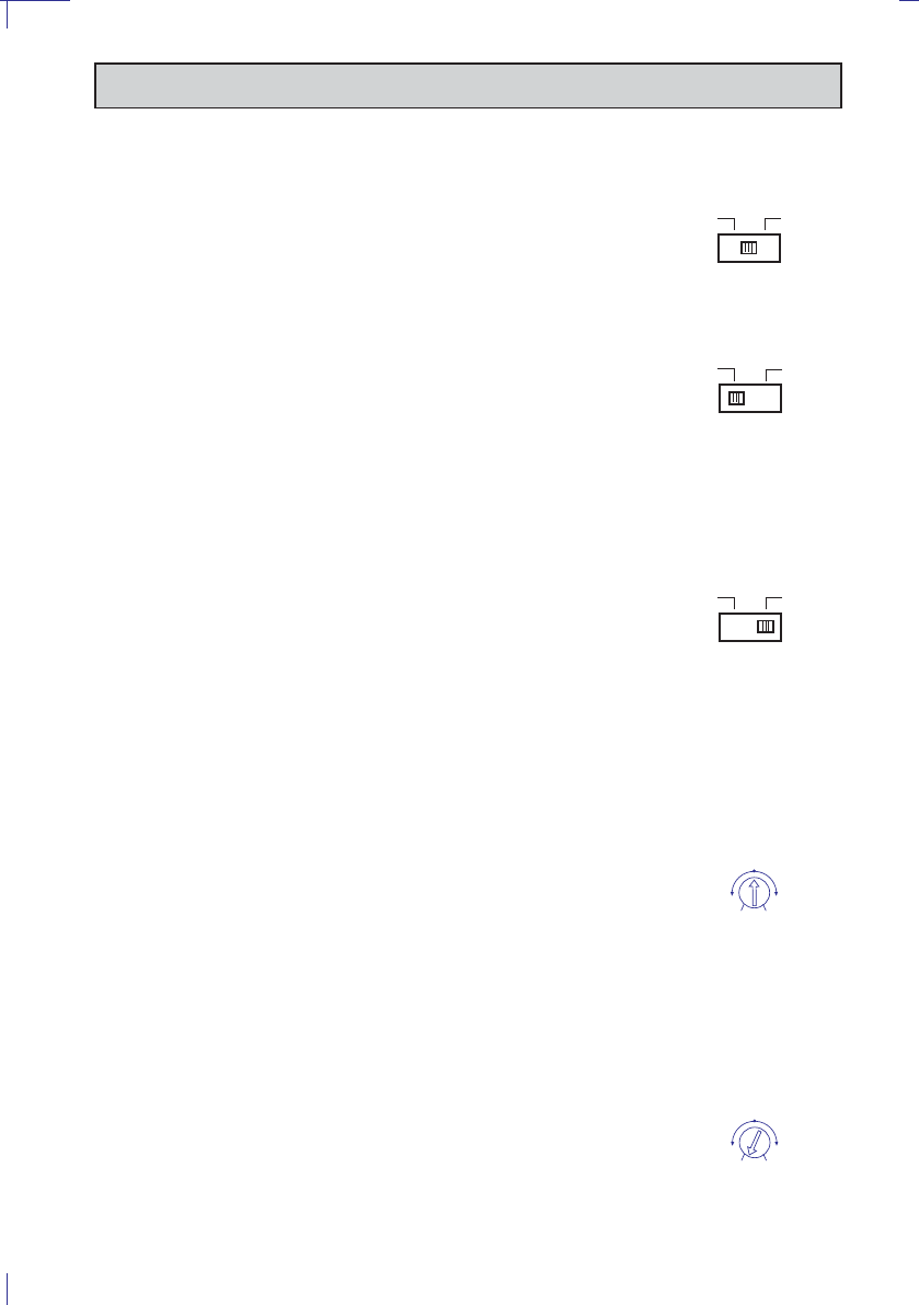
•INPUT MODE SELECTOR
This switch allows the user to specify the input signal to the amplifier.
a) STEREO MODE
b) LEFT MODE (L - MONO)
c) LEFT + RIGHT MODE (L+R)
•END STAGE WITH DISCRETE COMPONENTS (TRANSISTORS)
•HIGH PERFORMANCES, LOW NOISE LEVEL, PASSIVE AND ACTIVE COMPONENTS
•NO CURRENT LIMITATIONS
The current limitation circuits incorporated in traditional amplifiers may cause untimely clipping
and a low transient response. The absence of such circuits assures a low T.I.M. effect, an
excellent transient response and a perfect sound quality.
•RCA INPUT SENSITIVITY
The new amp has a 500mVsensitivity for ideal coupling with MACROM sources and, however,
it is possible to regulate the sensitivity from 100mV to 2V to facilitate coupling with any other
source present on the market.
•REMOTE ON AND OFF
On switching the head unit on or off, the amplifier is automatically switched on or off.
•ON/OFF INDICATOR
•THREEFOLD PROTECTION
Your unit is provided with three different protection devices, as befits all high-end products.
SOFT START: the amp powers gradually in order to avoid damage to the speakers in case the
head unit is switched on with the volume control set to maximum.
OVERHEATING: in case of wrong installation the unit enters the protection mode before being
damaged. As soon as the temperature returns to normal values, the unit resumes normal
operation.
OUTPUT SHORT CIRCUIT: in case of a short circuit at the speaker outlets the unit enters the
protection mode in order to avoid serious damage to the end-stage transistors. Normal operation
is resumed on eliminating the short circuit.
•CAPACITIVE/INDUCTIVE POWER SUPPLY FILTER
This filter reduces radio frequency interferences (RFI) and cuts off system noises (i.e. the whine
of the alternator).
8
MACROM INGLESE 42.15 - 42.17 17 FEBBRAIO 19939
FEATURES
9
•MOS-FET Power Supply
The 42.24/42.26 's great power is obtained by means of a special C-Mos-Fet supply unit which
offers constant efficiency and requires low electrical input. The results are excellent performances,
a linear and wide frequency response with high dynamics.
Libble takes abuse of its services very seriously. We're committed to dealing with such abuse according to the laws in your country of residence. When you submit a report, we'll investigate it and take the appropriate action. We'll get back to you only if we require additional details or have more information to share.
Product:
Forumrules
To achieve meaningful questions, we apply the following rules:
First, read the manual;
Check if your question has been asked previously;
Try to ask your question as clearly as possible;
Did you already try to solve the problem? Please mention this;
Is your problem solved by a visitor then let him/her know in this forum;
To give a response to a question or answer, do not use this form but click on the button 'reply to this question';
Your question will be posted here and emailed to our subscribers. Therefore, avoid filling in personal details.
Register
Register getting emails for Macrom 42.24 at:
new questions and answers
new manuals
You will receive an email to register for one or both of the options.
Get your user manual by e-mail
Enter your email address to receive the manual of Macrom 42.24 in the language / languages: English, German, French, Italian, Spanish as an attachment in your email.
The manual is 1,15 mb in size.
You will receive the manual in your email within minutes. If you have not received an email, then probably have entered the wrong email address or your mailbox is too full. In addition, it may be that your ISP may have a maximum size for emails to receive.
The manual is sent by email. Check your email
If you have not received an email with the manual within fifteen minutes, it may be that you have a entered a wrong email address or that your ISP has set a maximum size to receive email that is smaller than the size of the manual.
The email address you have provided is not correct.
Please check the email address and correct it.
Your question is posted on this page
Would you like to receive an email when new answers and questions are posted? Please enter your email address.