CONTENTS
2
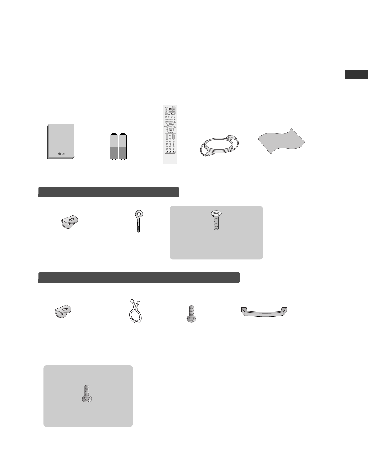
ACCESSORIES . . . . . . . . . . . . . . . . . . . . . . . . . . . . . . . . . . . . . . . . . . .1
INTRODUCTION
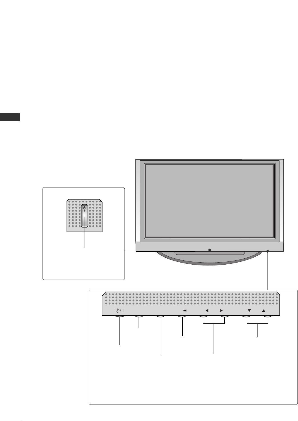
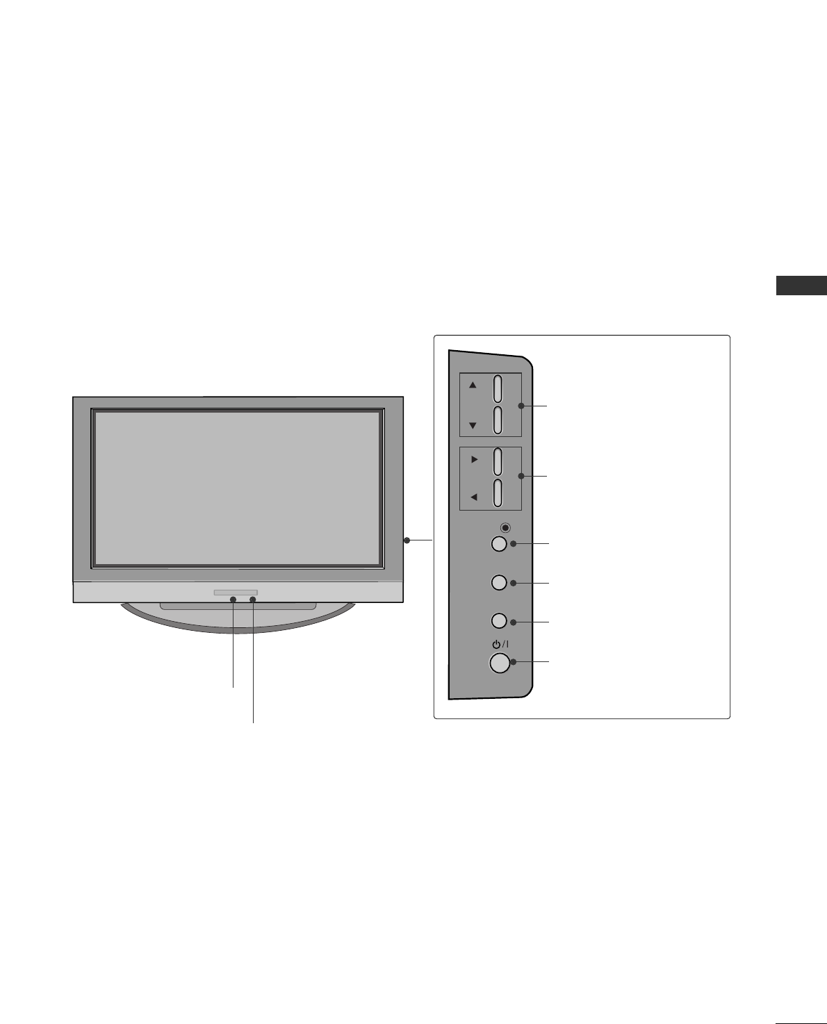
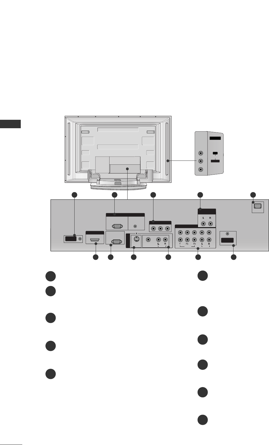
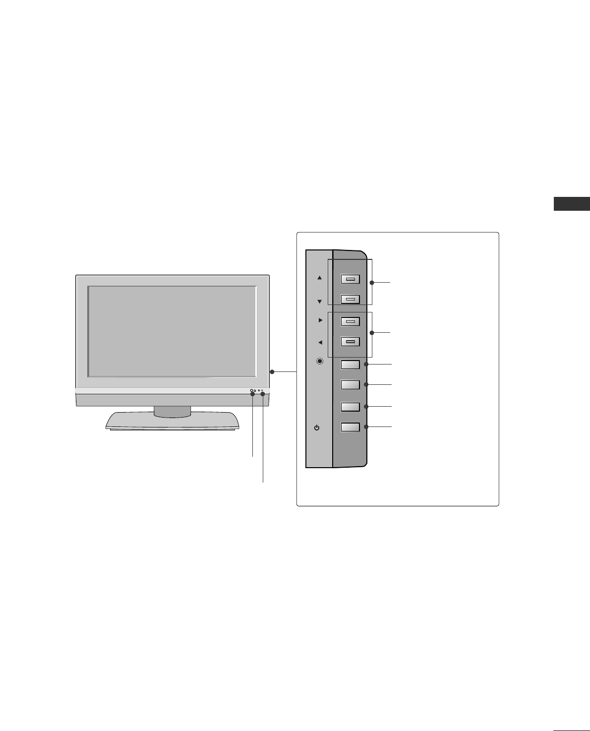
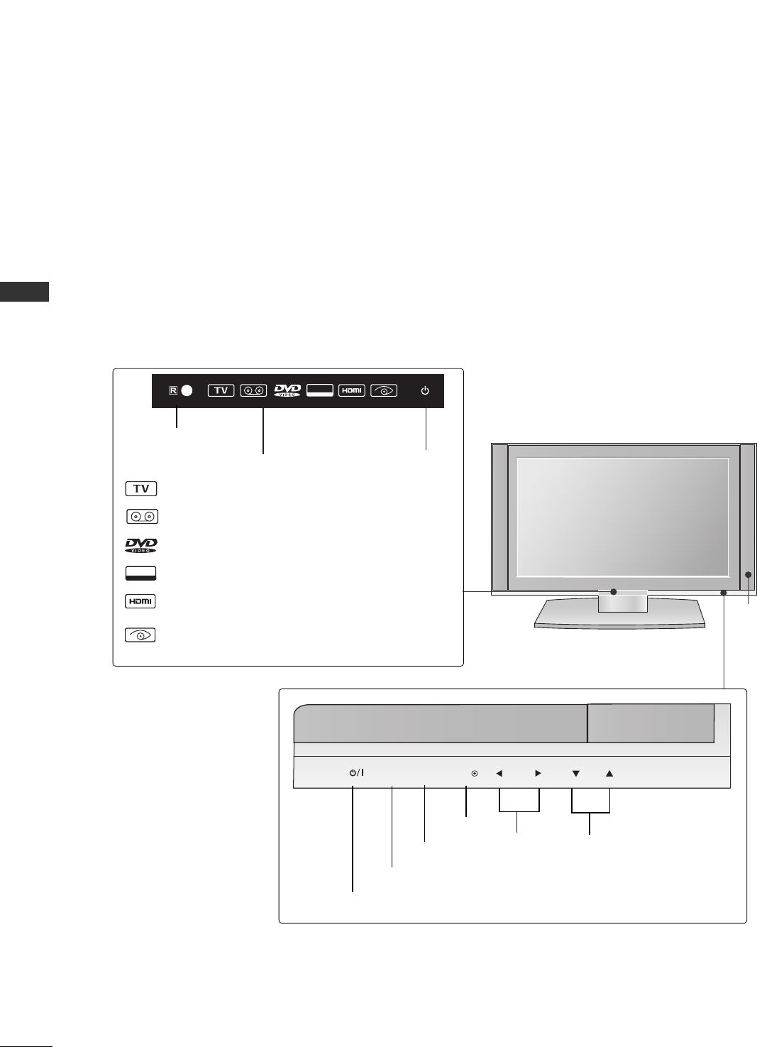
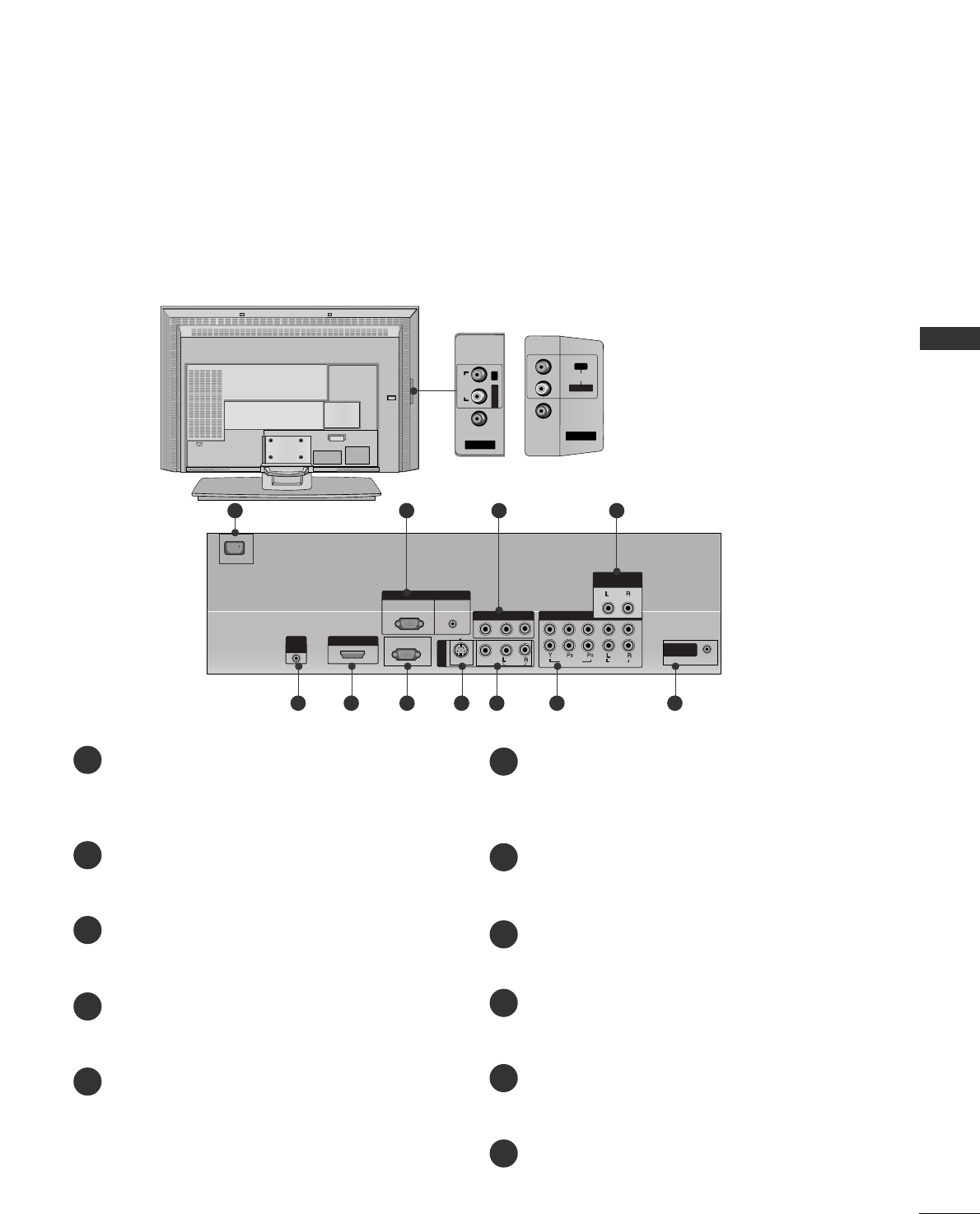
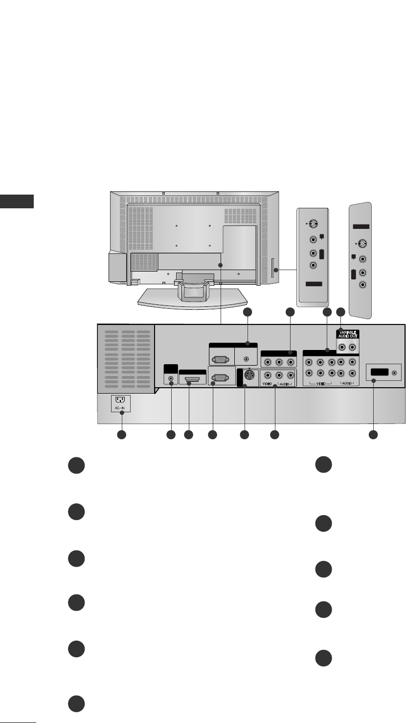
Controls / Connection Options . . . . . . . . . . . . . . . . . . . . . . . .
4-10
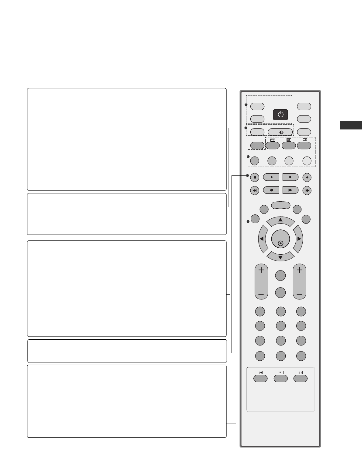
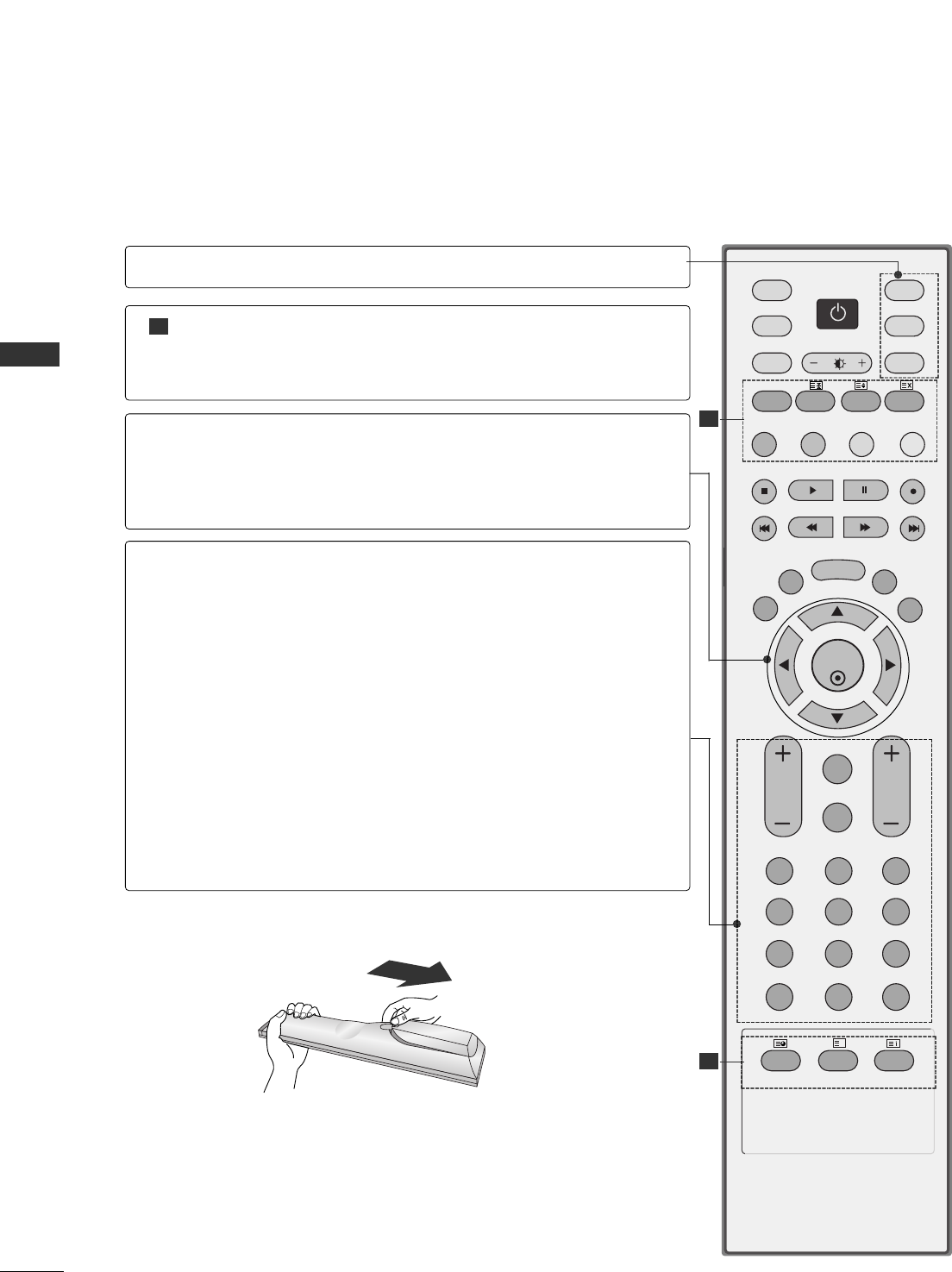
Remote Control Key Functions/
Installing Batteries
. . . . . . . . . . . . . . . . . . . . . . . . . . . . . . . . . . . . . . . .
11-12
TV MENU
On Screen Menus Selection and Adjustment . . . . .36
SSeettttiinngg uupp TTVV ssttaattiioonnss
Auto programme tuning
. . . . . . . . . . . . . . . . . . . . . . . . . . . . . . .
37
Manual programme tuning
. . . . . . . . . . . . . . . . . . . . . . . . . . . .
38
Fine tuning
. . . . . . . . . . . . . . . . . . . . . . . . . . . . . . . . . . . . . . . . . . . . . . . . . .39
Assigning a station name
. . . . . . . . . . . . . . . . . . . . . . . . . . . . . . .
40
Booster (Option)
. . . . . . . . . . . . . . . . . . . . . . . . . . . . . . . . . . . . . . . . .41
Programme edit
. . . . . . . . . . . . . . . . . . . . . . . . . . . . . . . . . . . . . . . . . . .42
Favourite programme
. . . . . . . . . . . . . . . . . . . . . . . . . . . . . . . . . . . .
43
Calling the programme table
. . . . . . . . . . . . . . . . . . . . . . . .
44
PPiiccttuurree MMeennuu OOppttiioonnss
PSM (Picture Status Memory)
. . . . . . . . . . . . . . . . . . . . . .45
Picture Adjustment (PSM-User option)
. . . . . . . . .46
CSM (Colour Status Memory)
. . . . . . . . . . . . . . . . . . . . . .47
Manual Colour Temperature Control
(CSM - User option)
. . . . . . . . . . . . . . . . . . . . . . . . . . . . . . . . . . . .48
Function
. . . . . . . . . . . . . . . . . . . . . . . . . . . . . . . . . . . . . . . . . . .49
ADVANCED
. . . . . . . . . . . . . . . . . . . . . . . . . . . . . . . . . . . . . . . . . . . . . . . . .50
Reset
. . . . . . . . . . . . . . . . . . . . . . . . . . . . . . . . . . . . . . . . . . . . . . . . . . . . . . . . . . .51
SSoouunndd MMeennuu OOppttiioonnss
SSM (Sound Status Memory)
. . . . . . . . . . . . . . . . . . . . . . .52
Sound Frequency Adjustment
(SSM - User option)
. . . . . . . . . . . . . . . . . . . . . . . . . . . . . . . . . . . .53
AVL (Auto Volume Leveler)
. . . . . . . . . . . . . . . . . . . . . . . . . . .54
Balance Adjustment
. . . . . . . . . . . . . . . . . . . . . . . . . . . . . . . . . . . . .54
Speaker
. . . . . . . . . . . . . . . . . . . . . . . . . . . . . . . . . . . . . . . . . . . . . . . . . . . . . . .55
Stereo/Dual Reception
. . . . . . . . . . . . . . . . . . . . . . . . . . . . . . . . .56
NICAM Reception
. . . . . . . . . . . . . . . . . . . . . . . . . . . . . . . . . . . . . . . .57
Speaker Sound Output Selection
. . . . . . . . . . . . . . . . . .57
TTiimmee MMeennuu OOppttiioonnss
Clock Setup . . . . . . . . . . . . . . . . . . . . . . . . . . . . . . . . . . . . . . . . . . . . . . . . .58
On/Off Time
. . . . . . . . . . . . . . . . . . . . . . . . . . . . . . . . . . . . . . . . . . . . . . .59
Auto Sleep
. . . . . . . . . . . . . . . . . . . . . . . . . . . . . . . . . . . . . . . . . . . . . . . . . .60
Sleep Timer
. . . . . . . . . . . . . . . . . . . . . . . . . . . . . . . . . . . . . . . . . . . . . . . . .60
SSppeecciiaall MMeennuu OOppttiioonnss
Child Lock
. . . . . . . . . . . . . . . . . . . . . . . . . . . . . . . . . . . . . . . . . . . . . . . . . . .61
ISM (Image Sticking Minimization) Method
. . .62
Low Power
. . . . . . . . . . . . . . . . . . . . . . . . . . . . . . . . . . . . . . . . . . . . . . . . . . .63
XD Demo
. . . . . . . . . . . . . . . . . . . . . . . . . . . . . . . . . . . . . . . . . . . . . . . . . . . .63
INSTALLATION
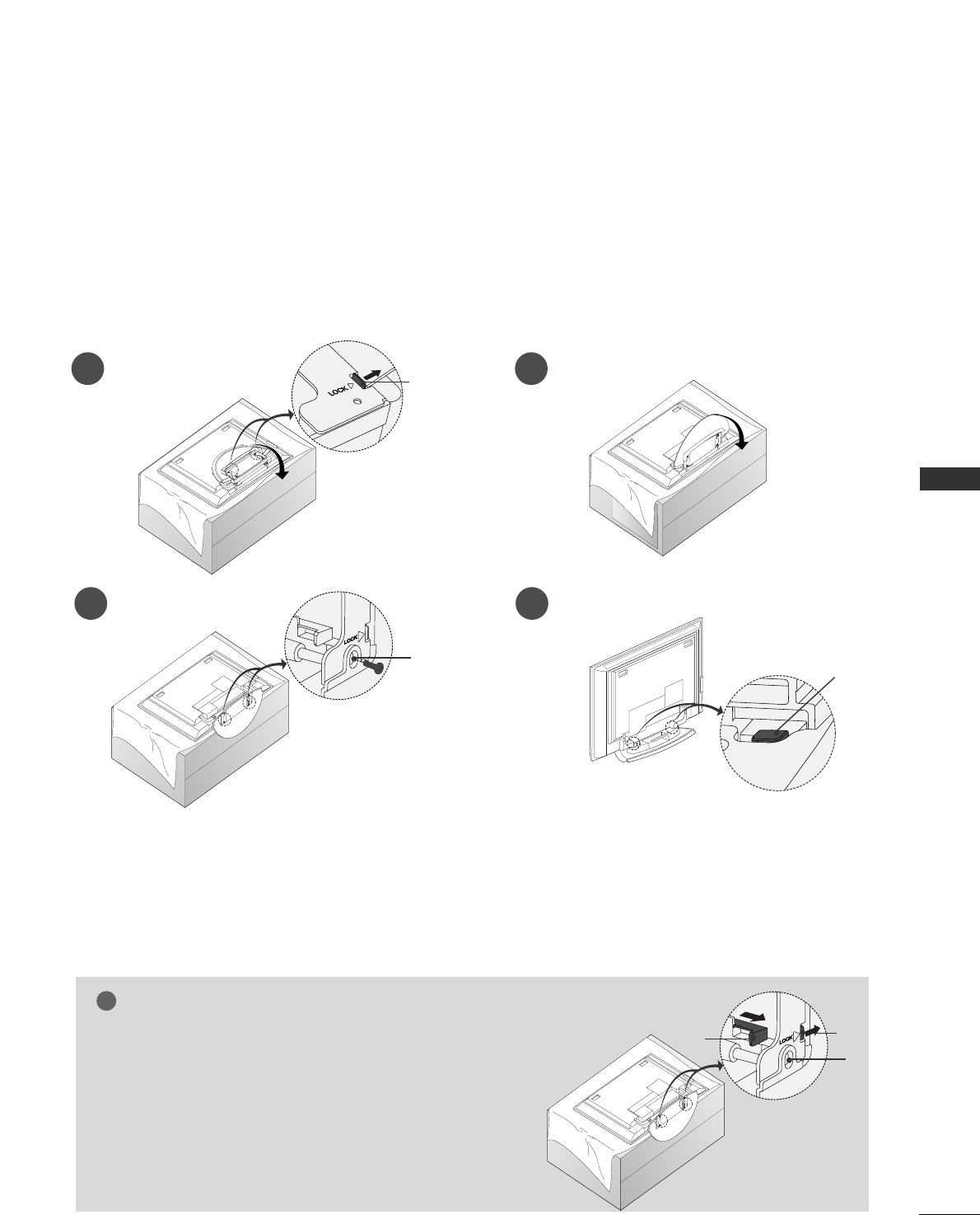
Unfolding The Base Stand
. . . . . . . . . . . . . . . . . . . . . . . . . . . . . . . . . . . .13
Stand Installation
. . . . . . . . . . . . . . . . . . . . . . . . . . . . . . . . . . . . . . . . . . . . . . . . .14
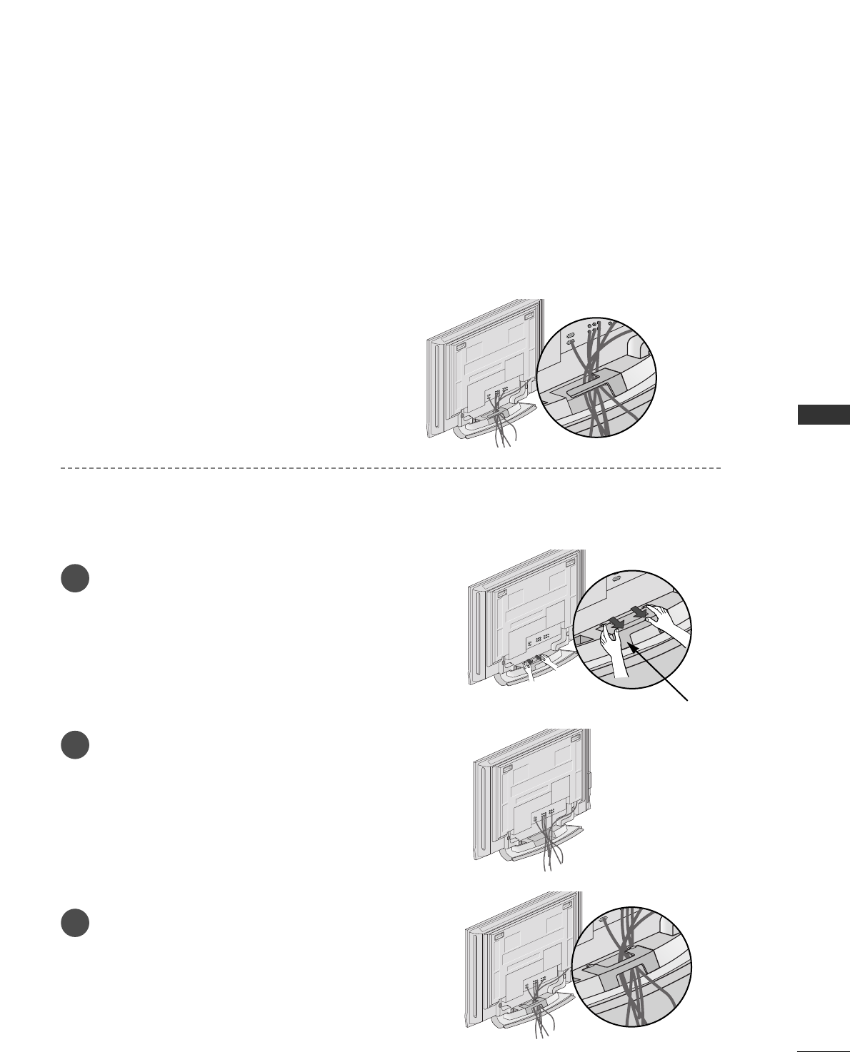
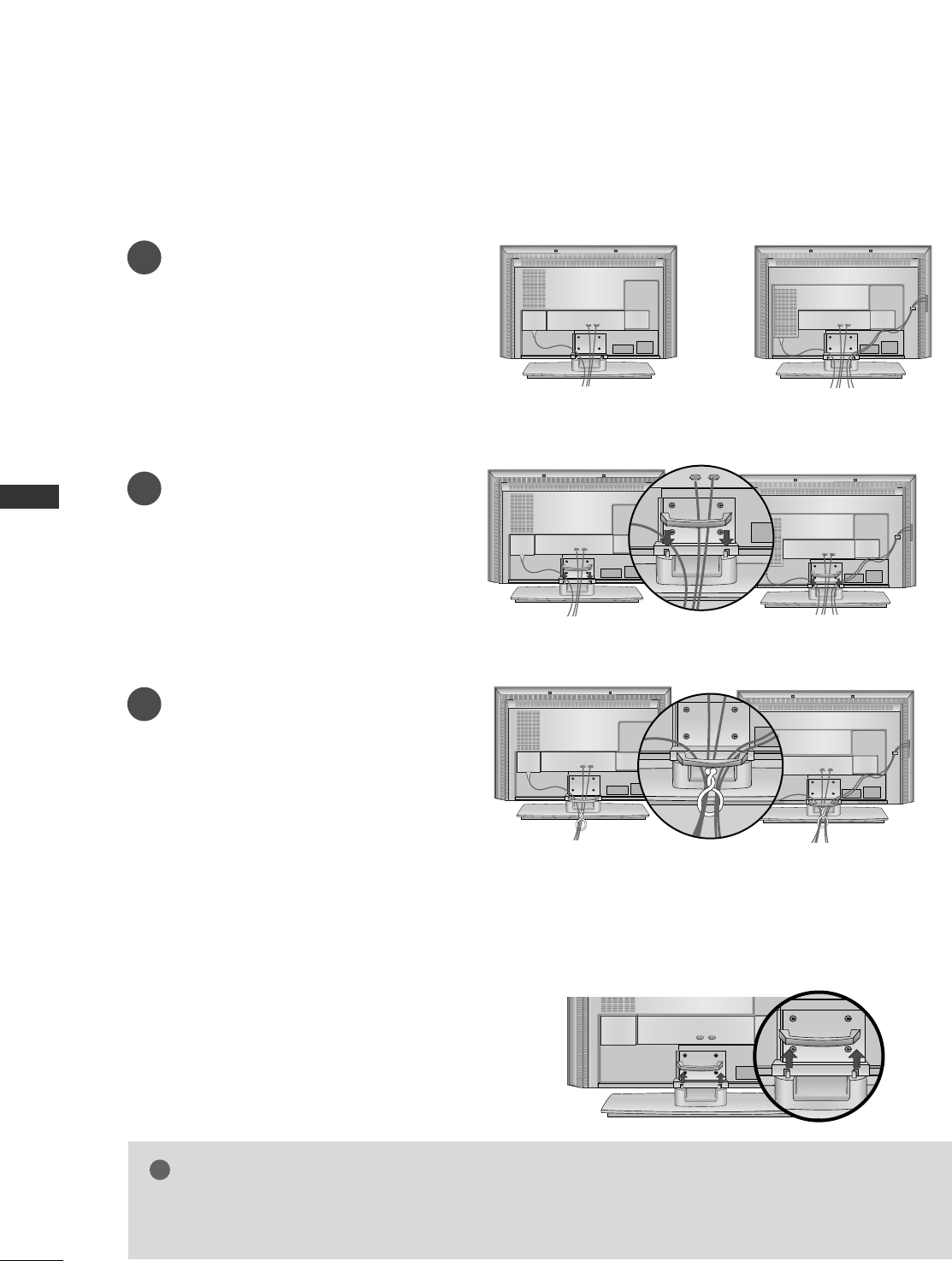
Basic Connection /
How to Remove the Cable Management
. . . . . . . . . . .15-16
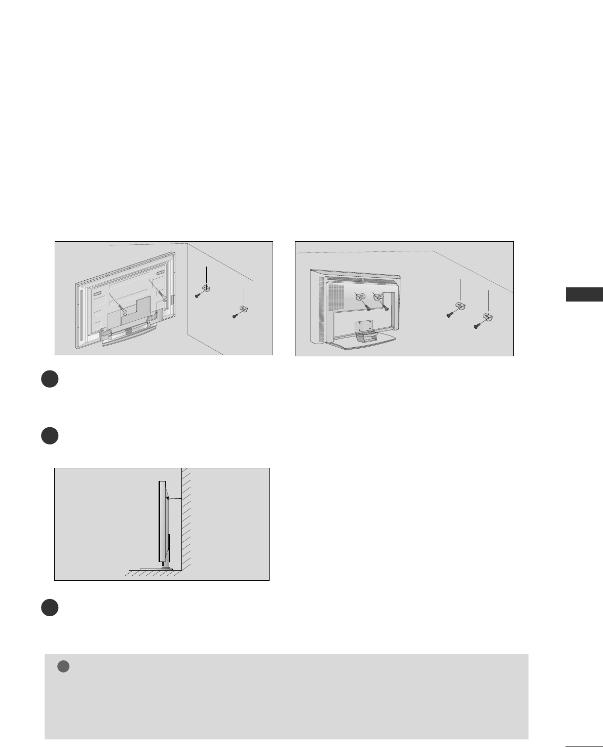
How to join the product assembly to the wall
to protect the set tumbling
. . . . . . . . . . . . . . . . . . . . . . . . . . . . . . . . . . .17
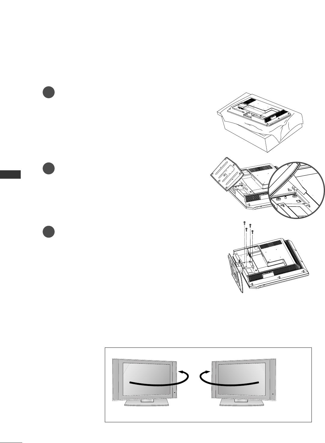
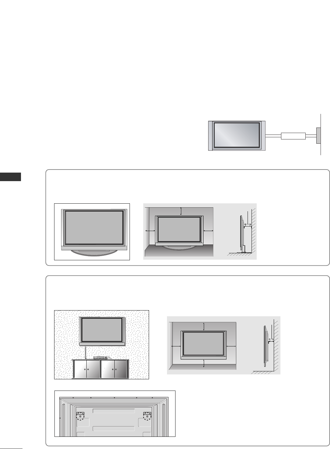
Installation
. . . . . . . . . . . . . . . . . . . . . . . . . . . . . . . . . . . . . . . . . . . . . . . . . . . . . . . . . . .18
CONNECTIONS & SETUP
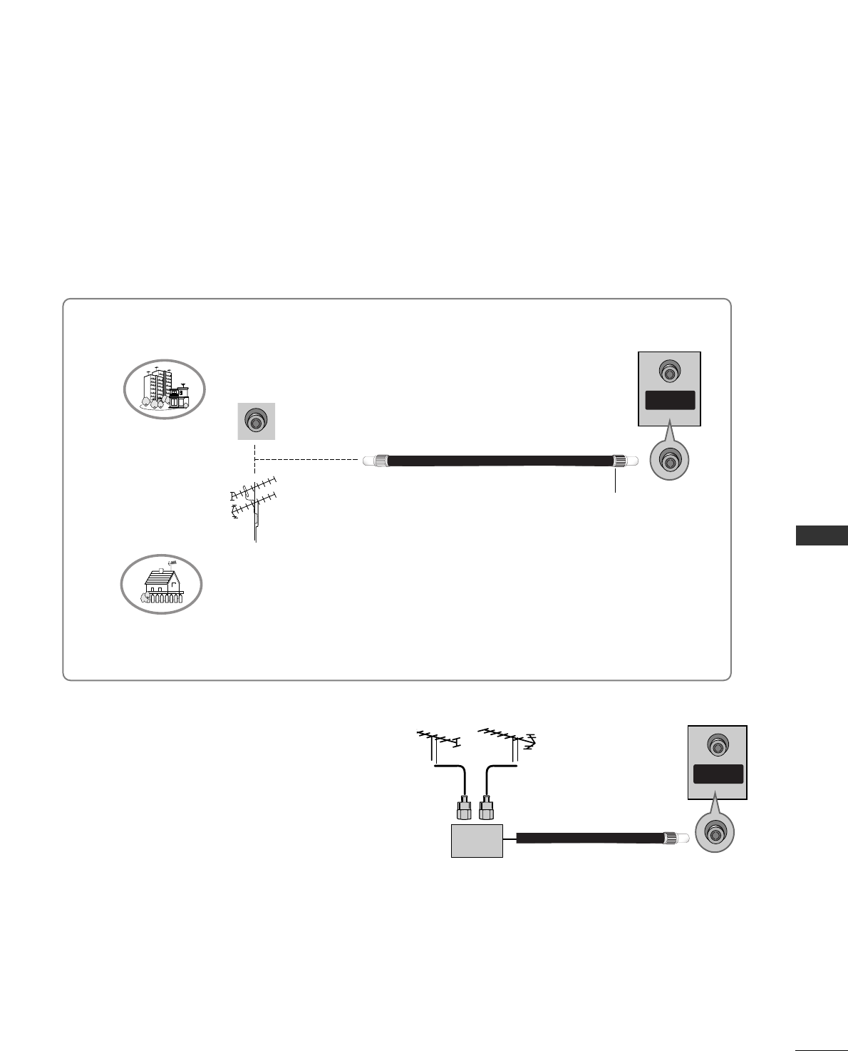
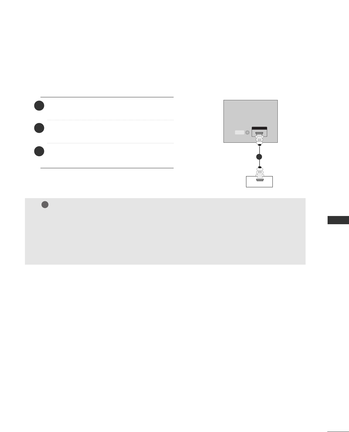
Antenna Connection
. . . . . . . . . . . . . . . . . . . . . . . . . . . . . . . . . . . . . . . . . . . .19
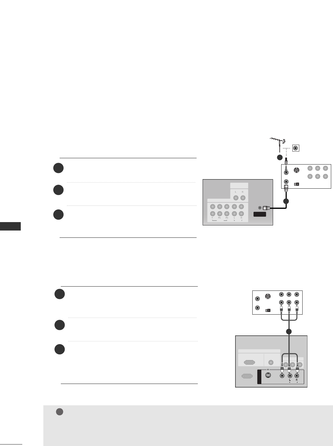
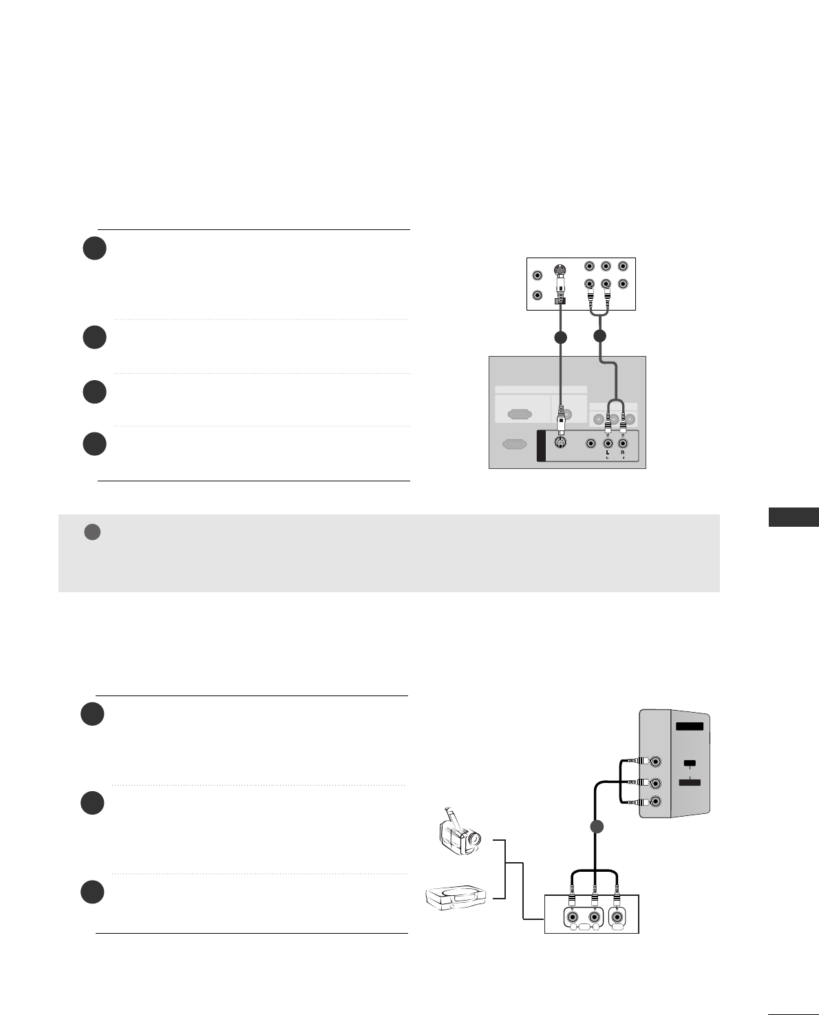
VCR SETUP/
EXTERNAL EQUIPMENT CONNECTIONS
. . . .20-21
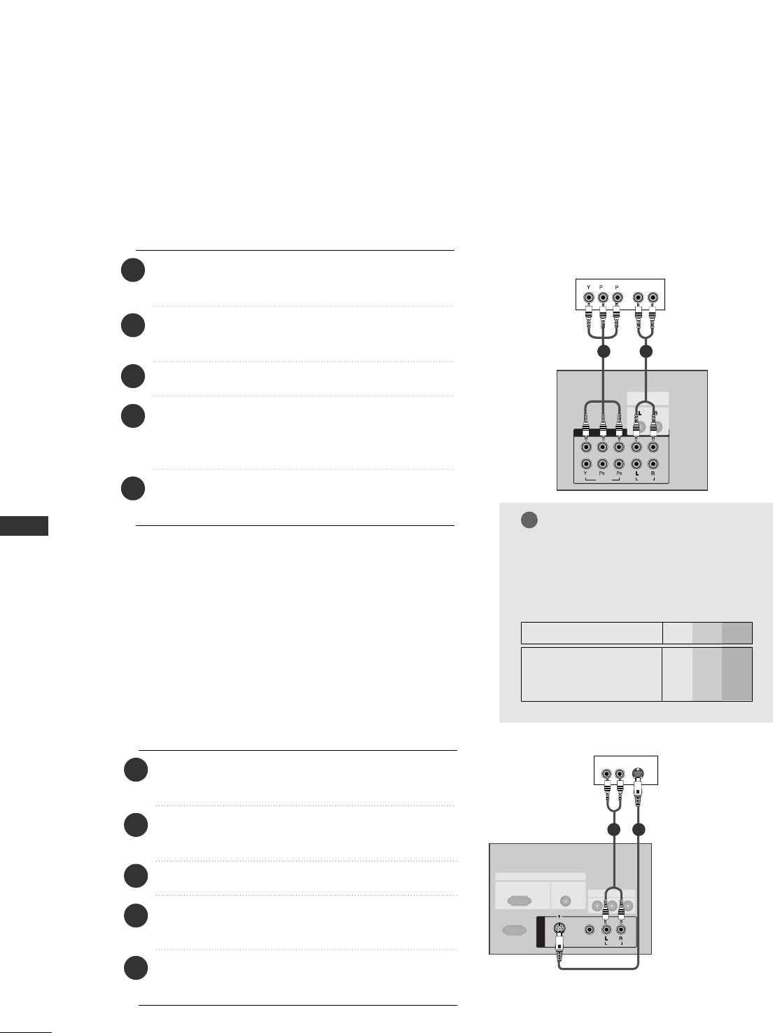
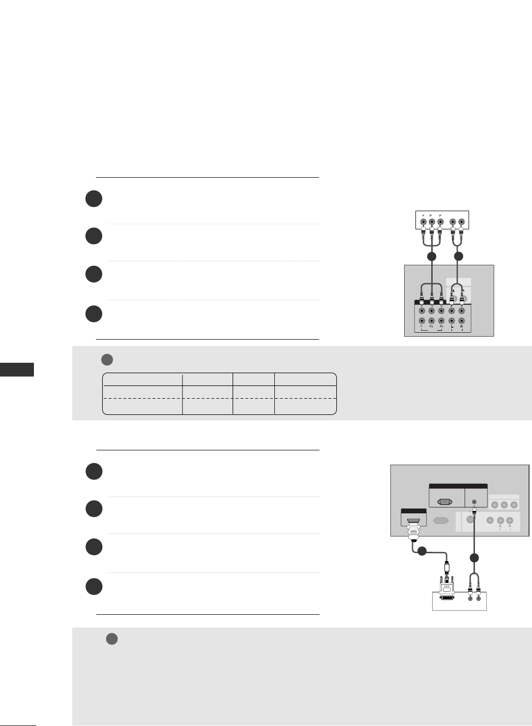
DVD SETUP
. . . . . . . . . . . . . . . . . . . . . . . . . . . . . . . . . . . . . . . . . . . . . . . . . . .22-23
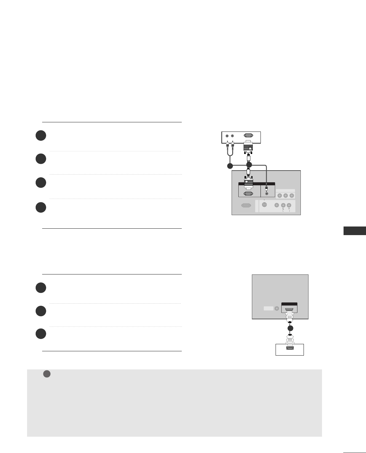
STB(SET-TOP BOX) SETUP
. . . . . . . . . . . . . . . . . . . . . . . . . . . . .24-25
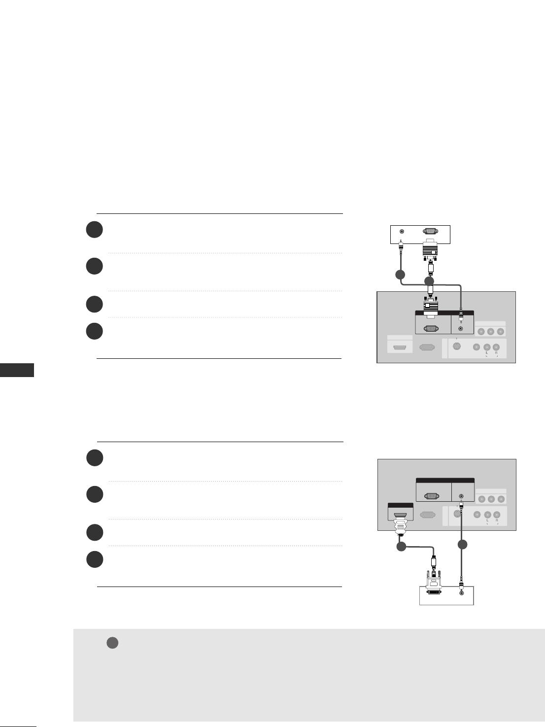
PC SETUP
. . . . . . . . . . . . . . . . . . . . . . . . . . . . . . . . . . . . . . . . . . . . . . . . . . . . . .26-28
TURNING THE TV ON
. . . . . . . . . . . . . . . . . . . . . . . . . . . . . . . . . . . . . . . .
29
SPECIAL FUNCTIONS
PPIIPP ((PPiiccttuurree--IInn--PPiiccttuurree)) // DDoouubbllee WWiinnddooww // PPOOPP
Watching PIP/Double Window/POP
. . . . . . . . . . . . . .30
Programme Selection for Sub Picture
. . . . . . . . . . . .30
Input Source Selection for Sub Picture
. . . . . . . . . .31
Sub Picture Size Adjustment (PIP mode only)31
Moving the Sub Picture (PIP mode only)
. . . . . . .31
Adjusting PIP Transparency (PIP mode only)
. .31
Swapping between main and sub pictures
. . . . . .32
POP
(Picture-out-of-Picture: Programme Scan)
. . . . .32
TTeelleetteexxtt
Switch on/off
. . . . . . . . . . . . . . . . . . . . . . . . . . . . . . . . . . . . . . . . . . . . . .33
SIMPLE Text
. . . . . . . . . . . . . . . . . . . . . . . . . . . . . . . . . . . . . . . . . . . . . . . . .33
TOP Text
. . . . . . . . . . . . . . . . . . . . . . . . . . . . . . . . . . . . . . . . . . . . . . . . . . . . .34
FASTEXT
. . . . . . . . . . . . . . . . . . . . . . . . . . . . . . . . . . . . . . . . . . . . . . . . . . . . .34
Special Teletext Functions
. . . . . . . . . . . . . . . . . . . . . . . . . . . .35
CONTENTS