577627
12
Zoom out
Zoom in
Previous page
1/58
Next page
AutoControl-Master ACM
ACM 3.0 Rev 10.05
GB
D
NL
F
DK
E
Bedienungsanleitung
Operating instructions
Gebruiksaanwijzing
Betjeningsvejledning
Mode d´emploi
Instrucciones para su uso
Istruzioni d'uso
Instrukcja Obsługi
Käyttöohje
Instruções de uso
6-15
16-25
26-35
36-45
46-55
56-65
66-75
76-85
86-95
96-105
I
PL
FIN
P
AutoControl-Master ACM
2
3
AutoControl-Master ACM
4
5
AutoControl-Master ACM
Der Laser schaltet sich
sicherheitshalber
ab und die Tilt-
LED leuchtet
ständig.
Einleitung
6 DEUTSCH
Self-Levelling-System (SLS)
Der AutoControl-Master ACM nivelliert
sich selbst. Er wird in die benötigte
Grundstellung gebracht, die Fein-
einstellung übernimmt sofort die
Automatik:
Das Self-Levelling-System (SLS) führt
horizontal und vertikal selbsttätig die
orthogonale Einstellung durch. Zwei
elektronische Messsensoren erfassen
dabei die x- und y-Achse. Wurde der
Rotationslaser um 90° gekippt, nivelliert
ein dritter Sensor die z-Achse. Der
Arbeitswinkel beträgt ± 6°.
Anti-Drift-System (ADS)
Das Anti-Drift-System (ADS) verhindert
Fehlmessungen. Das Funktionsprinzip:
Der Laser wird 45 Sekunden nach dem
Aktivieren des ADS permanent auf seine
korrekte Ausrichtung überprüft.
Wird das Gerät durch äußere Ein-
wirkungen bewegt, oder verliert der
Laser seine Höhenreferenz, schaltet sich
das Gerät sicherheitshalber ab und die
Tilt-LED leuchtet ständig.
Einrichten des
Lasers
Nach 45 Sekunden
startet die ADS-Über-
wachung
Fremdeinwirkung:
ADS schaltet den Laser
ab.
Tilt-Taste
aktiviert ADS
auto/man-Taste
SLS aus/ein
Ein
Fremd-
einwirkung
Einrichtphase SLS Aktivieren
des ADS
ADS scharf
nach 45 sec.
Beginn
Rotation
auto/man-Taste
Ein/Aus-Taste
Tilt-Taste
Bezeichnungen
DEUTSCH 7
IR-Empfangsfeld
Vertikalfuß
Nivellierschrauben
Prismenkopf Austritt Laser
RichtungstastenNeigungstasten
Austritt
Laserlotstrahl
x
y
z
x
z
y
Koordinatenzuordnung
Horizontal: Vertikal:
Vom SLS ausgerichtete
Ebene
Einrichten:
Schalten Sie den ACM ein. Während der
Laserstrahl blinkt, wird der Laser auto-
matisch ausgerichtet.
Hinweis: Sollte das Gerät
durch extreme Schieflage
(Winkel > ±6°) nicht in der
Lage sein, sich korrekt
auszurichten, schaltet es
sich nach 5 min. ab.
Funktionen:
1. Punkt-Modus
Bei dieser Funktion
kann der Laser mit den
Richtungstasten zur
Messebene genau
positioniert werden.
2. Rotations-Modus
3. Scan-Modus
Ein lichtintensives Segment von
unterschiedlicher Breite und
Position kann eingestellt werden.
4. Handempfänger-Modus
Max. 600 U/min
5. Neigungungs-Modus:
Horizontal
Im Horizontalbetrieb
richtet das SLS die X- und
Y-Achse aus. Wenn Sie
aber z.B. ein Gefälle
projizieren wollen, müssen Sie das SLS
mit der Taste auto/man ausschalten.
Mit den Tasten und kann jetzt die
Neigung der X-Achse verstellt werden.
Zum Verstellen der Neigung der
Y-Achse, drücken Sie zuvor die Tilt-
Taste .
Vertikal
Im Vertikalbetrieb richtet
das SLS die Laserebene
vertikal aus. Mit den
Tasten und können
Sie die Laserebene um die Y-Achse dre-
hen. (Hinweis: Der Referenzstrahl
bewegt sich horizontal) Wenn Sie das
SLS ausschalten, können Sie zusätzlich
nach dem Drücken der Tilt-Taste mit
den Tasten und die Laserebene nei-
gen.
8 DEUTSCH
Bedienungsanleitung
Vertikalfuß
herausklappen
ebene
Oberfläche
y
x
y
in einer Ebene
in zwei Ebenen
Hinweis zum Vertikalen Nivellieren:
Press: 90 U/min
150 U/min
300 U/min
450 U/min
600 U/min
DEUTSCH 9
Anti-Drift-System (ADS)
Das ADS ist nach dem Einschalten nicht
aktiv. Um das eingerichtete Gerät vor
Lageveränderungen durch
Fremdeinwirkung zu schützen, muss das
ADS durch Drücken der Tilt-Taste
aktiviert werden.
Achtung: Das ADS schaltet erst 45 sec.
nach vollständiger
Nivellierung des Lasers die
Überwachung scharf
(Einrichtphase).
Die ADS-Funktion wird durch Blinken
der Tilt-LED angezeigt.
Wir das Gerät durch Fremdeinwirkungen
bewegt, schaltet sich der Laser ab und
die Tilt-LED leuchtet ständig.
Das Gerät muss neu aus- und einge-
schaltet werden, um weiterarbeiten zu
können. Fehlmessungen werden so ein-
fach und sicher verhindert.
Arbeiten mit dem Zubehör
Handempfänger:
Schalten Sie den ACM
in den
Handempfängermodus:
SensoCommander: -Taste
drücken.
Hinweis: Um Fehlmessungen zu ver-
meiden, achten Sie bei der
Messung darauf, dass keine
Reflexionen an Fenstern o.ä.
entstehen.
Wechsel des ACM-Batteriefachs
Zum Wechseln zwischen Batteriefach
und Hochleistungsakku, lösen Sie bitte
die Befestigungsschraube am Boden des
Batteriefachs.
Bedienungsanleitung
Laserniveau
(a)
(b)
(c)
(d)
(e)
(f)
(a) Handempfänger über Laserniveau
– nach unten regulieren
(b) Exakt im Laserniveau
(c) Handempfänger unter Laserniveau
– nach oben regulieren
(d) Low-Battery Anzeige
(e) Ton An/Aus Anzeige
(f) Anzeige Messbereichsauswahl
Wichtiger Hinweis für ACM RF:
Zwischen Aus- und Einschalten des Rotationslasers ACM RF müssen mindestens
3 Sekunden liegen, damit eine zuverlässige Funkverbindung zwischen Senso-
Commander RF und ACM RF aufgebaut werden kann. Der ACM RF kann nur mit
dem SensoCommander Pro 300 RF fernbedient werden.
1 Ausgang IR-Signal
2 Empfangsfeld Laserstrahl
3 SpotLite Marking LED (nicht bei
SensoCommander Coolblue)
4 LED-Anzeige
5 Libelle
6 Befestigungsschraube
7 Universalhalterung
8 Befestigungshebel
9 Batteriefach (Rückseite)
10 Bedienfeld
11 LCD-Anzeige (Rückseite)
12 LCD-Anzeige
13 Umlaufende Markierungsnut
SensoCommander (optional) – Zubehör
Der SensoCommander vereinigt Fernbedienung und Laserempfänger.
3
1
6
7
8
10
13
2
3
1
6
7
8
10
9
12
11
13
5
SensoCommander 120:
(Dioden auch auf der Rückseite)
SensoCommander Pro:
2
4
9
Bedienungsanleitung
10 DEUTSCH
RoundLite Fernanzeige (optional)
Das System ist genial einfach: RoundLite und SensoCommander
Pro RF stehen per Funk-Technologie in Verbindung und bilden ein
intelligentes Netzwerk, siehe S.3. Das RoundLite dient dabei als
eine erweiterte Anzeige des Laserempfängers. Mit 6 extrahellen
Leucht-dioden zeigt das Gerät dann die Position des Lasers an.
Achtung: Nur für SensoCommander Pro 300 RF.
Arbeiten mit dem SensoCommander
Lautstärke
einstellen
Fein-Bereich
Modus mit kleinerer
Toleranz, für feines
Ausrichten. (z.B. mit
Messlatten, > 10 m)
Freihand-Bereich
Modus mit größerer
Toleranz, für grobes
Ausrichten von Hand
(< 50 m).
Bedienfeld
14 Punkt- und Rotationsmodus
15 Scan-Modus
16 Handempfänger-Modus
17 Position
18 Geschwindigkeit / Lautstärke / Winkelbereich
Der SensoCommander kann den Laserstrahl auf großer
Distanz erkennen. Bitte bewegen Sie den Senso-
Commander durch den Laserstrahl auf- und abwärts, bis
die mittlere Anzeige erscheint. Markieren Sie nun die
Messhöhe an der umlaufenden Markierungsnut. Das
SpotLite zeigt zusätzlich die Messhöhe an (nicht bei
SensoCommander CoolBlue).
17
18
16
14
15
Universalhalterung:
Der Empfänger kann mit der Universalhalterung an Messlatten
befestigt werden. Dafür die Universalhalterung an den
Laserempfänger einschieben und an der Messlatte mittels
Befestigungsschraube festschrauben. Zum Trennen des Empfängers
von der Universalhalterung, die Schnellarretierung in Richtung der
Pfeile lösen.
1
2
Hinweis:
Die Laser-Empfänger verfügen über 2 Toleranzbereiche: Fein- und Freihand-bereich.
Am SensoCommander 120 werden die Bereiche durch die LED’s angezeigt:
Feinbereich grün, Freihandbereich orange. Beim SensoCommander Pro werden die
beiden Bereich durch die Taste umgeschaltet.
Bedienungsanleitung
DEUTSCH 11
12 DEUTSCH
Kalibrierung
Überprüfung und Kalibrierung
Hinweis: Der ACM ist ein Qualitätsrotationslaser und wird 100%ig in der angege-
benen Toleranz im Werk eingestellt. Aus Gründen der Produkthaftung
möchten wir Sie auf folgendes hinweisen: Überprüfen Sie regelmäßig die
Kalibrierung vor dem Gebrauch nach Transporten und langer Lagerung.
Überprüfung und Kalibrierung
X-/Y-Achse
1. Gerät mit der zu überprüfen-
den Achse in Richtung
Zielwand stellen
2. Punkt 1 auf der Zielwand
markieren
3. Gerät um exakt 180° drehen
(ohne die Stativhöhe zu ver-
stellen)
4. Punkt 2 auf der Zielwand markieren
5. Elektronische Kalibrierung siehe nächste Seite.
Z-Achse
Bestimmung von Referenzmarken
1. Gerät horizontal in die Mitte zwischen
zwei Zielen stellen
2. Ref.-Marke A an Ziel A (z.B. Messlatte
markieren
3. Gerät um 180° drehen, ohne die
Höhe zu verstellen
4. Ref.-Marke B an Ziel B (z.B. Wand)
markieren
Kalibrierung
1. Gerät vertikal in die Nähe von
Ziel A positionieren
2. Den Abstand des Laserstrahls
(durch Punkt A
2) zu Ref.-Marke
A messen
3. Den gemessenen Abstand auf
Wand B übertragen (Punkt B
2).
Elektronische Kalibrierung
siehe nächste Seite.
B
A
B
A
P2
P1
M
½ L
½ L
min. 20 - 30 m
min. 20 - 30 m
B
2
A2
DEUTSCH 13
Kalibrierung
Die Kalibrierung erfolgt jetzt elektronisch
A. Kalibriermodus einschalten
Kalibrierung kann jetzt elektronisch mittels der Fernbedienung erfolgen.
1. Das Gerät ausschalten und mit gedrückter -Taste das Gerät wieder einschal-
ten ( -Taste kurz drücken). Dabei -Taste solange gedrückt halten, bis
-LED leuchtet. Danach kann die -Taste losgelassen werden.
2. Das Aufleuchten von einer der drei LED’s signalisiert welche Achse kalibriert wer-
den kann.
X-Achse = LED links, Y-Achse = LED Mitte, Z-Achse = LED rechts
3. Nun kann mit Hilfe der Fernbedienung der Kalibriervorgang fortgesetzt werden.
Durch Drücken der -Taste erfolgt die Umstellung der X-, Y- Achsen.
4. Für die Einstellung der Z-Achse die Kalibrierung für X-, Y- Achse beenden (siehe
D). Das Gerät vertikal aufstellen, das Gerät im Kalibriermodus einschalten und
erneut Kalibrierung komplett durchführen.
B. Überprüfung und Kalibrierung der X-/ Y-/ Z- Achsen
Siehe S. 12
C. Korrektur der Kalibrierung
Mit der und -Tasten der Fernbedienung (durch mehrmaliges Tippen) den
Punkt von seiner aktuellen Position auf die Höhe von Referenzpunkt M bzw. B2
fahren.
D. Beenden des Kalibriervorgangs
Abbrechen: Durch Abschalten des Gerätes wird die gesamte Kalibrierung verworfen
und der vorherige Zustand wieder hergestellt.
Speichern: Durch Drücken der -Taste wird die Kalibrierung gesichert.
auto
man
tilt
auto
man
auto
man
auto
man
Garantieerklärung
Als Hersteller übernehmen wir für dieses
Gerät eine Garantie von 24 Monaten ab
Kaufdatum. Innerhalb dieser
Garantiezeit beseitigen wir nach unserer
Wahl durch Reparatur oder Austausch
alle Mängel, die auf Material- oder
Herstellungsfehler beruhen. Von der
Garantie sind ausgenommen: Schäden,
die auf unsachgemäßen Gebrauch (z.B.
Betrieb mit falscher Stromart/ Spannung,
Anschlüsse an ungeeigneten Strom-
quellen) oder falscher Lagerung, zurück-
zuführen sind, normaler Verschleiß und
Mängel, die den Wert oder die
Gebrauchstauglichkeit nur unerheblich
beeinflussen.
Bei Eingriffen nicht von uns
autorisierter Stellen erlischt die Garantie.
Die Garantie tritt nur in Kraft, wenn das
Kaufdatum durch Stempel und
Unterschrift des Händlers bestätigt ist
und die Seriennummer des Gerätes auf-
geführt wurde. Sie kann in allen Ländern
in Anspruch genommen werden, in
denen dieses Gerät von UMAREX oder
ihren autorisierten Händlern verkauft
wird.
Im Garantiefall geben Sie bitte das voll-
ständige Gerät mit allen Informationen,
sowie Rechnung einem unserer Händler
oder senden Sie es an UMAREX.
Achtung: Nicht direkt in den
Strahl sehen!
Der Laser darf nicht in die
Hände von Kindern gelangen!
LASERSTRAHLUNG
NICHT IN DEN
STRAHL BLICKEN!
LASER KLASSE 2
LASER
14 DEUTSCH
Wandhalterung (optional)
Art-Nr: 080.70
Unbedingt notwendig für den Vertikal-
betrieb des AutoControl-Master ACM auf
dem Stativ. Für alle Laserliner Rotations-
und Linienlaser. Mit Höheneinstellung und
Klemmhalterung für das Aufhängen an
Konstruktionselementen.
Technische Daten (Änderungen vorbehalten)
DEUTSCH 15
ACM 3.0 / ACM 3.0 RF
Selbstnivellierbereich
+
Einstellgeschwindigkeit ca. 45 sek - über gesamten Arbeitswinkel
Genauigkeit
+ 1 mm / 10 m
Sensor elektronische Libelle
Nivellierung horizontal / vertikal
automatisch
Senkrechter Referenzstrahl
90° zur Rotationsebene
Rotationsgeschwindigkeit
90, 150, 300, 450, 600 U/min
Fernbedienung
Infrarot IR / ACM RF: Radiofrequenz RF
Laserwellenlänge
635 nm
Laser
Klasse 2 (EN 60825-1:2001)
Ausgangsleistung Laser
< 1 mW
Betriebsdauer Akku
ca. 40 h
Betriebsdauer Batterie
ca. 160 h, 2 x Typ D (Mono 1,5V)
Ladedauer Akku
ca. 14 h
Arbeitstemperatur
0°C ... +50°C
Gewicht
1,3 kg
SensoCommander (Optional)
Batterien / Stromversorgung:
SensoCommander Pro / SC 120
4 x Typ AA / 2 x Typ AAA
Batterielebensdauer
ca. 70 h (Mischbetrieb)
Reichweite Fernbedienung IR-Control
RF-Control
bis 15 m
bis 50 m (nur RF-Ausführung)
RF-Control (nur RF-Ausführungen)
Empfangsfrequenz / Konformität 896 - 870 MHz (SRD Radio) / CE 0700!
Laserempfangsbereich 120
SensoCommander: Pro 200
Pro 300
Pro 300 RF
120 m
200 m
300 m
300 m
Betriebstemperatur
0°C ... + 50°C
Lagertemperatur
-10°C ... + 70°C
Self-Levelling-System (SLS)
The AutoControl-Master ACM is of the
self-levelling kind. After it has been put
in the required basic position, fine
adjustment is being effected auto-
matically. Horizontal and vertical
orthogonal adjustments are effected by
the self-levelling system (SLS), while the
X-axis and the Y-axis are scanned by
two electronic measuring sensors. In
case the rotary laser has been tilted
by 90°, a third sensor levels the Z-axis.
The working angle is + 6°.
Anti-Drift-System (ADS)
The Anti-drift system (ADS) prevents
mismeasurements. Its principle of func-
tion: 45 seconds after ADS has been
activated, the laser is permanently being
checked for its correct adjustment.
In case the instrument has been moved
by external influences or the laser has
lost its frequency, the system switches
itself automatically off and the "tilt"-LED
shows a permanent light.
the laser switches itself
off for safety reasons,
the "tilt"-LED
shows a
permanent light.
Introduction
16 ENGLISH
adjustment of
the laser
after 45 seconds, ADS-
scanning begins
external influence: ADS
switches the laser off
push-button "tilt"
activates ADS
push-button auto/man
SLS off/on
on
external
influence
adjustment phase SLS ADS
activated
ADS in focus
after 45 sec.
rotation
begins
Designations
ENGLISH 17
IR-receiver
vertical foot
footscrews
prismatic head laser beam outlet
laser beam
outlet
x
y
z
x
z
y
coordinates allocation
horizontal: vertical:
level adjusted by the
SLS
push-button
"auto/man"
push-button
"on/off"
push-button
"tilt"
push-button
direction setting
push-button
inclination setting
Instruction Manual
18 ENGLISH
Setting up:
Switch on the ACM. While the laser
beam flashes, the laser is set
automatically.
Note: Should the
instrument, because of an
extremely inclined position,
not be able to adjust itself
properly, then it will switch
itself off after 5 min.
Functions:
1. Spot mode
With this function,
the laser can be
adjusted (with the
direction setting) properly in
relation to the measuring level.
2. Rotary mode
3. Scan mode:
The laser produces a segment
of intense light, with variable
width and position.
4. Hand receiver mode:
Max. 600 RPM
5. Slope mode:
Horizontal
In the horizontal mode of
operation, the SLS levels
the X-axis and the Y-axis.
If, for example, a slope is
to be projected, then the SLS
has to be switched off by pressing the
push-button "auto/man" .Now the
push-buttons and can be used to
adjust the incliniation over the X-axis.
Before adjusting the inclination over the
Y-axis, press the button "tilt" .
Vertical
In the vertical mode of
operation, the SLS levels
the laser level in the
vertical position. The
push-buttons and
can be used to rotate the laser level aro-
und the Y-axis. (Note: The reference
beam moves horizontally) With the SLS
switched off, the laser level can be incli-
ned by operation of the push-buttons
and after the push-button "tilt" has
been pressed.
y
x
y
x
x-y
Unfold the
vertical support
place the instru-
ment on a level
surface
Instructions for vertical levelling:
Press: 90 RPM
150 RPM
300 RPM
450 RPM
600 RPM
Instruction Manual
ENGLISH 19
Anti-Drift-System (ADS)
After the instrument has been switched
on, the ADS is not active. In order to
protect the instrument from
position changes caused by external
influences, the ADS has to be
activated by pressing the push-button
"tilt" .
Attention: The ADS-function will switch
on the control of the
laser 45 seconds after the
laser has completely been
levelled.
Should the instrument be moved by
external influences, then the laser is
switched off and the "tilt"-LED shows a
permanent light.
The instrument has to be switched off
and -on again if work is to be
commenced. This is a simple and reliable
prevention of misreadings.
Operation with the optional
hand receiver:
Switch the
ACM to the hand
receiver mode:
SensoCommander:
Press the -button.
Note: Carefully prevent reflections
from windows etc. as this could
cause misreadings.
Change of the ACM-battery
Loosen screw at the bottom of the bat-
tery compartment in order to
change from battery compartment to
high performance rechargeable
battery.
(a) hand receiver above laser level –
adjust downwards
(b) precisely on laser level
(c) hand receiver below laser level
– adjust upwards
(d) low battery display
(e) acoustic signal display "on/off"
(f) display measuring range selection
Laser level
(a)
(b)
(c)
(d)
(e)
(f)
Important information for ACM RF!
There must be a time delay of at least 3 seconds between turning off and on the
ACM RF unit as only this enables a reliable radio contact. The ACM RF can only
be remote controlled with the SensoCommander Pro 300 RF!
20 ENGLISH
Instruction Manual
1 IR output signal
2 Receiver field for laser beam
3 SpotLite marking LED (not with
SensoCommander Coolblue)
4 LED display
5 Vial
6 Securing screw
7 Universal mount
8 Securing lever
9 Battery compartment (on back)
10 Control panel
11 LCD display (on back)
12 LCD display
13 All-round marking groove
SensoCommander (optional) - Accessory
The SensoCommander is an all-in-one remote control and laser receiver unit.
3
1
6
7
8
10
13
2
3
1
6
7
8
10
9
12
11
13
5
SensoCommander 120:
(Diodes also on the back)
SensoCommander Pro:
2
4
9
RoundLite Signal Transmitter (optional)
This system is ingeniously simple: RoundLite and SensoCommander Pro
RF communicate with each other via radio technology to form an
intelligent network, see page 3. RoundLite thereby acts as an extended
display of the laser receiver. With 6 extra-bright LEDs, RoundLite shows
the exact position of the laser.
Note: For SensoCommander Pro RF only.
ENGLISH 21
Instruction Manual
Working with the SensoCommander
Volume
adjustment:
Precision range:
Mode with smaller
tolerance for precise
alignment (e.g. with
measuring staff, > 10 m).
Free-hand range:
Mode with greater
tolerance for less precise
alignment by hand
(< 50 m).
Control panel
14 Spot mode / rotary mode
15 Scan mode
16 Hand receiver mode
17 Position
18 Speed / Volume / Angle range
The SensoCommander can recognise the laser beam over
long distances. Move the SensoCommander up and
down through the laser beam until the middle display
appears. Now mark the height on the all-round marking
groove. The Spotlite additionally shows the measured
height (not on SensoCommander CoolBlue).
17
18
16
14
15
Universal mount:
The receiver can be installed on levelling staffs with the aid of
the universal mount. To do this, insert the universal mount
into the laser receiver and secure on the levelling staff with
the aid of the screw. To release the universal mount from the
laser receiver, turn the quick release lock in the direction of the
arrow.
1
2
Note: The laser receiver has two tolerance settings: Precision and free-hand
setting. On the SensoCommander 120, the settings are indicated by LEDs:
precision setting: green; free-hand setting: orange. On the SensoCommander Pro,
changeover between the settings is done by the button.
Calibration
22 ENGLISH
Control and Calibration
Note: The ACM is a quality rotation laser, the tolerances of which are by 100%
preset in the factory. For reasons of product liability, however, we wish to
inform you that the calibration should be checked regularly after the
instrument has been transported or stored for an extended period.
Control and Calibration
X-/y-axis
1. Install instrument with the
axis to be controlled pointing
towards a wall.
2. Mark point 1 on this wall
3. Turn instrument by precisely
180° (without changing tri-
pod height).
4. Mark point 2 on the wall.
5. For electronic calibration see next page.
Z-axis
Determination of reference markings
1. Place instrument horizontally in the midd-
le between two targets.
2. Mark reference marking A on target A
(for instance levelling staff).
3. Turn instrument by precisely 180°
(without changing tripod height).
4. Mark reference marking B on target B
Calibration
1. Set up instrument vertically
near target A.
2. Measure distance of beam
(through marking A2) to
marking A.
3. Transfer measured distance to
target B (marking B2). For
electronic calibration see next
page.
B
A
P2
P1
M
½ L
½ L
min. 20 - 30 m
min. 20 - 30 m
B
A
B
2
A2
ENGLISH 23
Calibration
Calibration is now done electronically
A. Switch on calibration mode
Calibration can now be done electronically using the remote control.
1. Switch off the tool and, with the -button depressed, switch on again (briefly
press the -button). Keep the -button depressed down until the
- LED lights up. The -button can now be released.
2. One of the three LEDs will light up to show which axis can be calibrated.
X-axis = left LED, Y-axis middle LED, Z-axis = right LED
3. Calibration can now be continued using the remote control.
To change over between the X and Y axes, press the -button.
4. To adjust the Z axis, end calibration for the X and Y axes (see D). Position the
tool vertically, switch on in calibration mode, and again perform the complete
calibration process.
B. Checking and calibration of the X/Y/Z axes
See page 22
C. Correcting the calibration
Using the and buttons of the remote control (by repeated pressing),
move the point from its present position to the level of reference point M or B2.
D. Finishing the calibration
Cancel: By switching off the tool, the calibration adjustments made so far will be
lost and the preceding condition restored.
Save: By pressing the -button, the calibration is saved.
auto
man
tilt
auto
man
auto
man
auto
man
Warranty
The manufacturer grants a warranty for
this instrument for a period of 24
months after date of purchase. Within
this period we will, at our own
discretion, repair all defects based on
faulty material or workmanship, or we
will replace these parts.
Excluded from this warranty are:
damages caused by improper use
(operation with unsuitable electrical
power/tension; connection to unsuitable
power sources) or storage, normal wear
and also defects which do not or do
only hardly minimze the value or the
suitability of the instrument.
This warranty becomes null and void
in cases unauthorized persons attempt
to repair this instrument.
The warranty only becomes valid when
the date of purchase has been
verified by stamp and signature of the
dealer, and the serial number of the
device is to be stated, too.
The warranty is valid in all countries
where this instrument is being sold by
UMAREX or by authorized dealers.
In case of a claim under this warranty
please return this instrument, together
with all accompanying information and
the invoice, to an authorized dealer or
to the manufacturer.
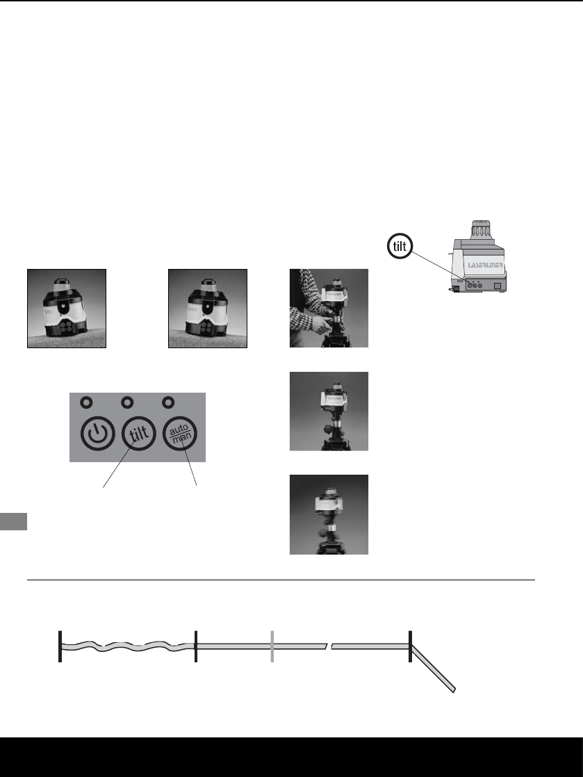
Caution: Do not look directly into
the beam!
Keep laser out of reach of
children!
LASERBEAM
DO NOT STARE INTO
THE BEAM!
LASER CLASS 2
LASER
24 ENGLISH
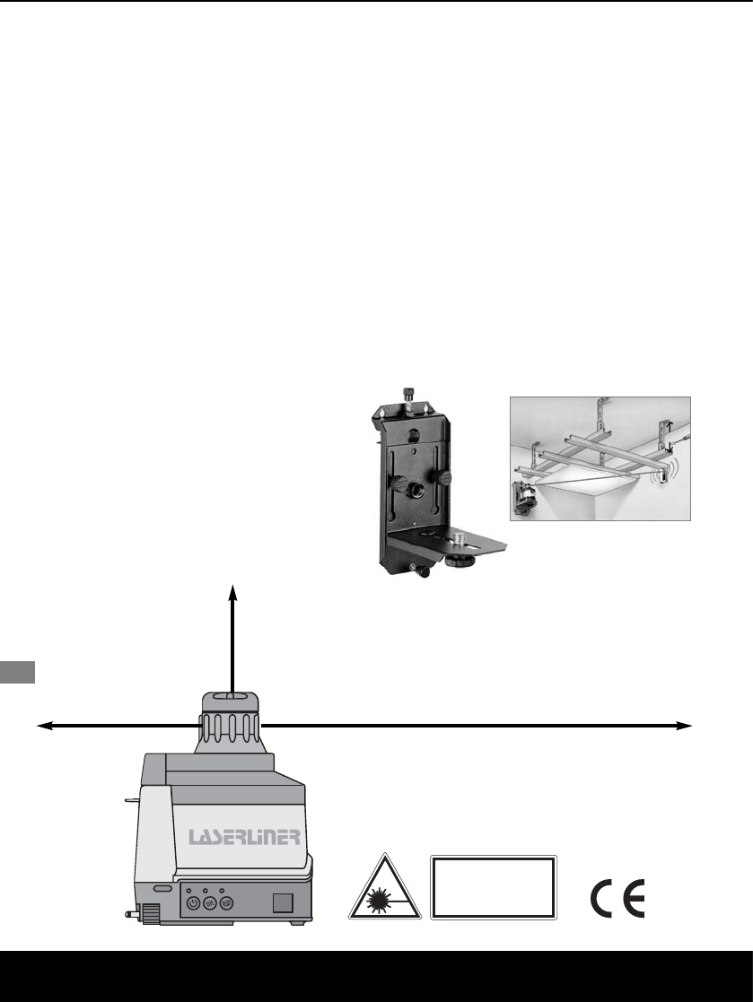
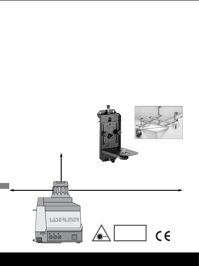
Wall Mount (optional)
Order No: 080.70
Essential for vertical operation of the
AutoControl Master ACM on tripod.
For all Laserliner rotary- and linelasers,
height adjustment, clamp holder
for attachment to structural elements.
ENGLISH 25
Technical Data (Subject to technical alterations)
ACM / ACM RF
Self-levelling range
+ 6° (horizontal)
Adjustment speed approx. 45 sec – on entire working angle
Precision
+ 1 mm / 10 m
Horizontal / vertical levelling
Automatic
Sensor
Electronic levelling device
Perpendicular reference beam
90° to the plane of rotation
Rotation speed
90, 150, 300, 450, 600
RPM
Remote control
Infrared IR / ACM RF: Radiofrequenz RF
Laser wavelength
635 nm
Laser
Class 2 (EN 60825-1:2001)
Laser output rating
< 1 mW
Rechargeable batt. operating time
approx. 40 h
Non-rechargeable battery life
approx. 160 h, 2 x type D (Mono 1,5V)
Battery recharging time
approx. 14 hours
Working temperature range
0°C ... 50°C
Weight
1.3 kg
SensoCommander (Optional)
Batteries / Power supply:
SensoCommander Pro / SC 120
4 x type AA / 2 x type AAA
Battery life
approx. 70 h (mixed operation)
Remote control range IR-Control
RF-Control
up to 15 m
up to 50 m (only RF-version)
RF-Control (only RF-version)
Frequency / Specification
896 - 870 (SRD Radio) / CE 0700!
Laser reception range 120
SensoCommander: 200
Pro 300
Pro 300 RF
120 m
200 m
300 m
300 m
Operating temperature
0°C ... 50°C
Storage temperature
-10°C ... 70°C
auto/man-toets
aan/uit-toets
tilt-toets
Benamingen
NEDERLANDS 27
IR-ontvangstveld
verticale voet
nivelleer-
schroeven
prismakop uittrede laser
richtingtoetsenhellingtoetsen
uittrede laser-
straal
x
y
z
x
z
y
coördinatentoekenning
horizontaal verticaal
door SLS uitgelijnd vlak
Gebruiksaanwijzing
NEDERLANDS 29
Anti-Drift-System (ADS)
Het ADS is na het aanschakelen niet
actief. Om het ingerichte apparaat te
beschermen tegen positiewijzigingen
door externe invloeden, moet het ADS
worden geactiveerd door de tilt-toets
in te drukken.
Opgelet: Het ADS schakelt pas 45 sec.
na volledige nivellering van de
laser de bewaking scherp
(inrichtfase).
De ADS-functie wordt getoond door
knipperen van de tilt-LED. Wordt het
apparaat bewogen door externe invloe-
den, dan schakelt de laser uit en de tilt-
LED licht continu op.
Het apparaat moet opnieuw uit- en aan-
geschakeld worden om verder te kun-
nen werken. Foutieve metingen worden
zo eenvoudig en zeker vermeden.
Werken met toebehoren
Handontvanger:
Schakel de
ACM in de
handontvangst-
modus:
SensoCommander: -knop
indrucken.
Aanwijzing: Om foutieve metingen te
vermijden moet u er bij de
meting op letten, dat er
geen reflecties ontstaan
aan ramen e.d.
Wisselen van de ACM-batterijhouder
Om te wisselen tussen batterijhouder en
hoogvermogensaccu maakt u de beve-
stigingsschroef op de bodem van de
batterijhouder los.
(a) handontvanger boven laserniveau
– naar beneden regelen
(b) exact op laserniveau
(c) handontvanger beneden
laserniveau – naar boven regelen
(d) Low-Battery indicatie
(e) toon aan/uit indicatie
(f) indicatie meetbereikselectie
Laser level
(a)
(b)
(c)
(d)
(e)
(f)
Belangrijke aanwijzing voor ACM RF:
Tussen het uit- en aanschakelen van de rotatielasers ACM RF moet minstens
3 seconden liggen, opdat een zuivere radioverbinding tussen SensoCommander
RF en ACM RF kan worden opgebouwd. De ACM RF kan enkel met de
SensoCommander Pro 300 RF bedient worden.
12


Need help? Post your question in this forum.

Forumrules


Report abuse

Libble takes abuse of its services very seriously. We're committed to dealing with such abuse according to the laws in your country of residence. When you submit a report, we'll investigate it and take the appropriate action. We'll get back to you only if we require additional details or have more information to share.

Product:

For example, Anti-Semitic content, racist content, or material that could result in a violent physical act.

For example, a credit card number, a personal identification number, or an unlisted home address. Note that email addresses and full names are not considered private information.

Forumrules

To achieve meaningful questions, we apply the following rules:

Register

Register getting emails for Laserliner AutoControl-Master ACM at:


You will receive an email to register for one or both of the options.


Get your user manual by e-mail

Enter your email address to receive the manual of Laserliner AutoControl-Master ACM in the language / languages: English, German, Dutch, Danish, French, Italian, Polish, Portuguese, Spanish, Finnish as an attachment in your email.

The manual is 2,07 mb in size.


You will receive the manual in your email within minutes. If you have not received an email, then probably have entered the wrong email address or your mailbox is too full. In addition, it may be that your ISP may have a maximum size for emails to receive.

The manual is sent by email. Check your email

If you have not received an email with the manual within fifteen minutes, it may be that you have a entered a wrong email address or that your ISP has set a maximum size to receive email that is smaller than the size of the manual.

The email address you have provided is not correct.

Please check the email address and correct it.

Your question is posted on this page

Would you like to receive an email when new answers and questions are posted? Please enter your email address.


Info