DICHIARAZIONE DI CONFORMITA’ DEL COSTRUTTORE .................................................................................................................................6
NORME PER L’INSTALLAZIONE ..........................................................................................................................................................................6
VASO DI ESPANSIONE APERTO ..................................................................................................................................................................................................................................................7
VASO DI ESPANSIONE CHIUSO ..................................................................................................................................................................................................................................................8
COLLEGAMENTO E CARICO DELL’IMPIANTO .......................................................................................................................................................................................................................9
PROTEZIONI DELLE TRAVI ...........................................................................................................................................................................................................................................................9
COLLEGAMENTO ALLA CANNA FUMARIA ..........................................................................................................................................................................................................................11
ARIA PER LA COMBUSTIONE ...................................................................................................................................................................................................................................................11
VENTILAZIONE ED AERAZIONE DEI LOCALI DI INSTALLAZIONE ...............................................................................................................................................................................12
COMBUSTIBILI AMMESSI / NON AMMESSI ....................................................................................................................................................12
ACCENSIONE A BASSE EMISSIONI..........................................................................................................................................................................................................................................14
MANCANZA DI ENERGIA ELETTRICA ....................................................................................................................................................................................................................................14
FUNZIONAMENTO NEI PERIODI DI TRANSIZIONE ...........................................................................................................................................................................................................15
UTILIZZO ESTIVO DEL PRODOTTO. ........................................................................................................................................................................................................................................15
MANUTENZIONE E CURA .................................................................................................................................................................................15
FERMO ESTIVO ...............................................................................................................................................................................................................................................................................16
DETERMINAZIONE DELLA POTENZA TERMICA .............................................................................................................................................17
CONDIZIONI DI GARANZIA ..............................................................................................................................................................................18
SCHEMA DI INSTALLAZIONE. .......................................................................................................................................................................... 84
DATI TECNICI. ....................................................................................................................................................................................................98
La regolazione dei registri necessaria per l’ottenimento della resa calorica nominale è la seguente: vedi capitolo DESCRIZIONE TECNICA.
Questo è un apparecchio a combustione intermittente.
Nel caso che la temperatura dell’acqua superi la temperatura d’intervento delle sicurezze, sospendere immediatamente il
carico di legna, vericare la diminuzione della temperatura dell’acqua e della amma eliminando le cause del
surriscaldamento (chiudendo eventualmente il registro d’aria). Qualora nel termoprodotto sia collegata l’acqua sanitaria
si può aprire il rubinetto dell’acqua calda per velocizzare il rareddamento dell’apparecchio stesso.
Oltre che dalla regolazione dell’aria per la combustione, l’intensità della combustione e quindi la resa calorica del vostro apparecchio è
inuenzata dal camino. Un buon tiraggio del camino richiede una regolazione più ridotta dell’aria per la combustione, mentre uno scarso
tiraggio necessita maggiormente di un’esatta regolazione dell’aria per la combustione.
Per vericare la buona combustione, controllate se il fumo che esce dal camino è trasparente. Se è bianco signica che l’apparecchio non è
regolato correttamente o la legna è troppo bagnata; se invece il fumo è grigio o nero è segno che la combustione non è completa (è necessaria
una maggior quantità di aria secondaria).
ATTENZIONE: Quando si aggiunge combustibile sopra alle braci in assenza di amma si potrebbe vericare un elevato sviluppo di
fumi. Se questo dovesse avvenire si potrebbe formare una miscela esplosiva di gas e aria e, in casi estremi vericare un’esplosione.
Per motivi di sicurezza si consiglia di eseguire una nuova procedura di accensione con utilizzo di piccoli listelli.
MANCANZA DI ENERGIA ELETTRICA
Nella eventualità di una improvvisa interruzione dell’energia elettrica durante il normale funzionamento dell’impianto, sarà necessario
compiere queste semplici manovre per evitare che il termoprodottovada in ebollizione in seguito al mancato funzionamento della pompa.
• Chiudere completamente i registri dell’aria primaria e secondaria in modo da soocare il più possibile la amma
• Chiudere il registro fumi, se presente, per limitare ulteriormente l’ausso dell’aria comburente attraverso eventuali fessure.
14
ITALIANO
FUNZIONAMENTO NEI PERIODI DI TRANSIZIONE
Durante il periodo di transizione, ovvero quando le temperature esterne sono più elevate, in caso di improvviso aumento della temperatura
si possono avere dei disturbi alla canna fumaria che fanno si che i gas combusti non vengono aspirati completamente. I gas di scarico non
fuoriescono più completamente (odore intenso di gas).
In tal caso scuotete più frequentemente la griglia e aumentate l’aria per la combustione. Caricate in seguito una quantità ridotta di combustibile
facendo sì che questo bruci più rapidamente (con sviluppo di amme) e si stabilizzi così il tiraggio della canna fumaria. Controllate quindi che
tutte le aperture per la pulizia e i collegamenti al camino siano ermetici. In caso di incertezza rinunciate all’utilizzo del termoprodotto.
ATTENZIONE: Per nessuna ragione si dovrà accendere il fuoco prima che l’impianto non sia stato completamente riempito d’acqua;
il farlo comporterebbe un danneggiamento gravissimo a tutta la struttura. L’impianto va tenuto costantemente pieno d’acqua
anche nei periodi in cui non è richiesto l’uso del termoprodotto. Durante il periodo invernale un’eventuale non attività va arontata
con l’aggiunta di sostanze antigelo.
UTILIZZO ESTIVO DEL PRODOTTO.
Mantenere l’impianto completamente riempito d’acqua. L’assenza di acqua nell’impianto comporterebbe un danneggiamento
gravissimo di tutta la struttura.
ATTENZIONE:per nessuna ragione si deve accendere il fuoco se prima l’impianto non sia stato completamente riempito d’acqua;
il farlo comporterebbe un danneggiamento gravissimo di tutta la struttura.
Onde evitare l’ebollizione dell’acqua nella caldaia, la pompa di circolazione dell’impianto dovrà essere SEMPRE in funzione per poter smaltire
sui radiatori, o sul puer, o su qualsiasi altra struttura di assorbimento termico il calore ceduto all’acqua dalla caldaia.
Se la pompa non dovesse circolare o, per qualsiasi ragione la temperatura dell’acqua dovesse superare i 95°C interviene la
valvola del D.S.A. scaricando calore tramite acqua a perdere. Si raccomanda di monitorare la temperatura dell’acqua nel
termoprodotto durante l’uso estivo per evitare interventi ripetuti della valvola DSA che ne potrebbero compromettere il
buon funzionamento.
MANUTENZIONE E CURA
Controllare e pulire, almeno una volta all’anno, la presa d’aria esterna. Il camino deve essere regolarmente ramazzato dallo spazzacamino.
Fate controllare dal Vostro spazzacamino responsabile di zona la regolare installazione del prodotto, il collegamento al camino e l’aerazione.
IMPORTANTE: LA MANUTENZIONE DEVE ESSERE ESEGUITA ESCLUSIVAMENTE AD APPARECCHIO FREDDO.
Si possono usare esclusivamente parti di ricambio espressamente autorizzate ed oerte da La NORDICA S.p.A.. In caso di bisogno
Vi preghiamo di rivolgerVi al Vs rivenditore specializzato.
L’ APPARECCHIO NON PUÒ ESSERE MODIFICATO!
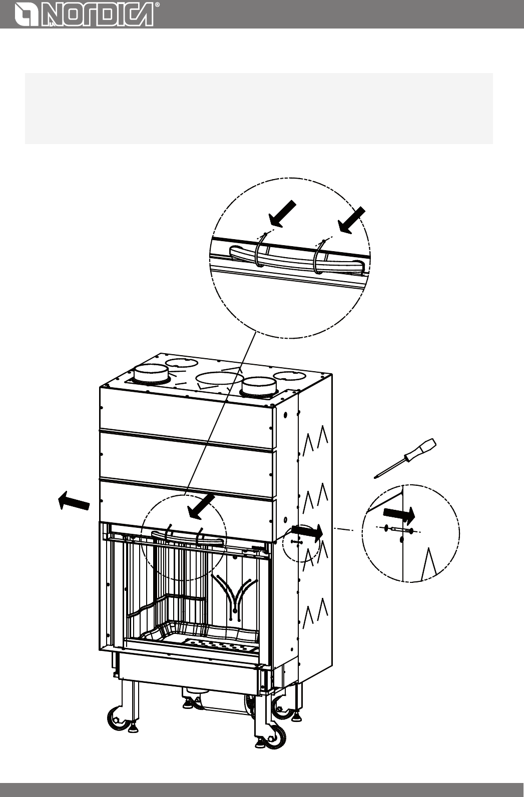
PULIZIA VETRO
Dopo aver vericato che la porta sia totalmente abbassata, sbloccare il chiavistello superiore (Figura 11 pos.A) aprirla a ribalta, pulire il vetro,
chiudere la ribalta e bloccare il chiavistello prima di risollevare la porta.
Tramite uno specico ingresso dell’aria secondaria la formazione di deposito di sporco, sul vetro della porta, viene ecacemente rallentata.
Non può comunque mai essere evitata con l’utilizzo dei combustibili solidi (es. legna umida ) e questo non è da considerarsi come un difetto
dell’apparecchio .
IMPORTANTE: la pulizia del vetro panoramico deve essere eseguita solo ed esclusivamente a apparecchio freddo per
evitarne l’esplosione. Per la pulizia si possono usare dei prodotti specici oppure, con una palla di carta di giornale (quotidiano)
inumidita e passata nella cenere.
Non usare comunque panni, o prodotti abrasivi o chimicamente aggressivi.
15
ITALIANO
La corretta procedura di accensione, l’utilizzo di quantità e tipi di combustibili idonei, il corretto posizionamento del registro dell’aria secondaria,
il suciente tiraggio del camino e la presenza dell’aria comburente sono indispensabili per il funzionamento ottimale dell’apparecchio e per
mantenere pulito il vetro.
ROTTURA DEI VETRI: i vetri essendo in vetroceramica resistenti no ad uno sbalzo termico di 750°C, non sono soggetti a
shock termici. La loro rottura può essere causata solo da shock meccanici (urti o chiusura violenta della porta ecc.). Pertanto
la sostituzione non è in garanzia.
PULIZIA CASSETTO CENERE
Tutti i prodottihanno una griglia focolare ed un cassetto per la raccolta della ceneri. Vi consigliamo di svuotare periodicamente il cassetto
dalla cenere e di evitarne il riempimento totale, per non surriscaldare la griglia. Inoltre Vi consigliamo di lasciare sempre 3-4 cm di cenere nel
focolare.
ATTENZIONE: le ceneri tolte dal focolare vanno riposte in un recipiente di materiale ignifugo dotato di un coperchio stagno.
Il recipiente va posto su di un pavimento ignifugo, lontano da materiali inammabili no allo spegnimento e rareddamento
completo delle ceneri.
PULIZIA CANNA FUMARIA
La corretta procedura di accensione, l’utilizzo di quantità e tipi di combustibili idonei, il corretto posizionamento del registro dell’aria secondaria,
il suciente tiraggio del camino e la presenza d’aria comburente sono indispensabili per il funzionamento ottimale dell’apparecchio e per
mantenere pulito il vetro.
Almeno una volta all’anno è consigliabile eseguire una pulizia completa, o qualora sia necessario (problemi di mal funzionamento con
scarsa resa). Un eccessivo deposito di fuliggine (creosoto) può provocare problemi nello scarico dei fumi e l’incendio della canna fumaria.
La pulizia deve essere eseguita esclusivamente ad apparecchio freddo. Questa operazione, dovrebbe essere svolta da uno
spazzacamino che contemporaneamente può eettuare un’ispezione.
Durante la pulizia bisogna togliere dall’apparecchio il cassetto cenere, la griglia ed il deettore fumi per favorire la caduta della fuliggine.
I deettori sono facilmente estraibili dalle loro sedi in quanto non sono ssati con nessuna vite. A pulizia eseguita gli stessi vanno riposizionati
nelle loro sedi (Figura 9).
ATTENZIONE: La mancanza del deettore fumi provoca una forte depressione, con una combustione troppo veloce,
eccessivo consumo di legna con relativo surriscaldamento dell’apparecchio.
Almeno una volta all’anno è consigliabile eseguire una pulizia dei particolari A e B, Figura 10 o qualora sia necessario (problemi di mal
funzionamento con scarsa resa). I particolari A e B sono facilmente estraibili dalle loro sedi in quanto non sono ssati con nessuna vite. A
pulizia eseguita gli stessi vanno riposizionati nelle loro sedi
FERMO ESTIVO
Dopo aver eettuato la pulizia del focolare, del camino e della canna fumaria, provvedendo all’eliminazione totale della cenere ed altri
eventuali residui, è opportuno chiudere tutte le porte con i relativi registri focolare. Nel caso in cui l’apparecchio venga disconnesso dal
camino, è opportuno chiudere il foro di uscita.
E’ consigliabile eettuare l’operazione di pulizia della canna fumaria almeno una volta all’anno; vericando nel contempo l’eettivo stato
delle guarnizioni che se non risultassero perfettamente integre - cioè non più aderenti alla stufa - non garantirebbero il buon funzionamento
dell’apparecchio! Si renderebbe quindi necessaria la loro sostituzione.
In caso di umidità del locale dove è posto l’apparecchio, sistemare dei sali assorbenti all’interno del focolare.
Proteggere le parti in ghisa, se si vuole mantenere inalterato nel tempo l’aspetto estetico, con della vaselina neutra.
Vericare il livello dell’acqua del vaso di espansione e fare uscire l’eventuale aria dell’impianto satando i radiatori, vericare inoltre la
funzionalità degli accessori idraulici ed elettrici (centralina, circolatore).
ATTENZIONE: Per nessuna ragione si dovrà accendere il fuoco prima che l’impianto non sia stato completamente riempito d’acqua;
il farlo comporterebbe un danneggiamento gravissimo a tutta la struttura. L’impianto va tenuto costantemente pieno d’acqua
anche nei periodi in cui non è richiesto l’uso del termoprodotto.
MANUTENZIONE GUIDE ESTENSIBILI
Le porte per funzionare in maniera silenziosa, adabile e robusta vengono ssate a delle guide estensibili a sfere. Usando continuamente
l’apparecchio, con il tempo, il lubricante delle guide stesse tende progressivamente ad esaurirsi rendendole quindi meno scorrevoli e più
rumorose. Per questo motivo in dotazione ad ogni apparecchio viene fornito del grasso per alta temperatura in maniera da rendere possibile
la lubricazione, da parte dell’utente, delle guide qualora questo si renda necessario (eccessiva rumorosità o riduzione di scorrevolezza).
Dopo aver totalmente sollevato la porta del camino fare uso di una siringa e applicare internamente sul binario nel punto visibile più alto
possibile, due palline di grasso (corrispondenti a 0.5 ml della scala graduata di una siringa).
Fare attenzione ad non superare la quantità consigliata. Ripetere la stessa operazione sull’altro binario, sollevare ed abbassare più
volte la porta in modo che il grasso si distribuisca su tutte le sfere.
ATTENZIONE: usare esclusivamente il grasso fornito da La NORDICA.
16
ITALIANO
MANUTENZIONE DELL’IMPIANTO IDRAULICO
Un eccessivo deposito di incrostazioni sulle pareti interne del focolare riduce notevolmente l’ecienza dello scambio termico,
pertanto quando necessario bisogna asportare le incrostazioni mediante una spatola d’acciaio. Non usare mai sostanze corrosive
che possono danneggiare il termoprodotto e la caldaia.
Ad impianto spento, una volta all’anno, eseguire le seguenti veriche:
• Controllare la funzionalità e l’ecienza delle valvole di scarico termico e di sicurezza. Qualora queste fossero difettose contattare
l’installatore autorizzato. E’ TASSATIVAMENTE VIETATO LA RIMOZIONE O MANOMISSIONE DI TALI SICUREZZE.
• Vericare l’isolamento termico del tubo di riempimento e del tubo di sicurezza.
• Accertarsi che l’impianto sia carico ed in pressione, controllare il livello dell’acqua all’interno del vaso di espansione, e vericarne la
funzionalità assicurandosi anche dell’ecienza del tubo di sicurezza.
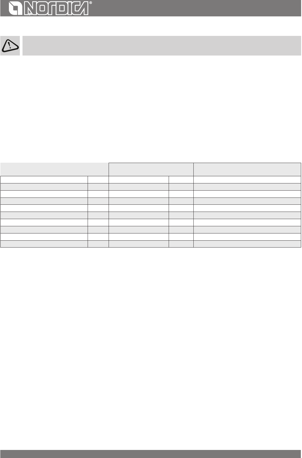
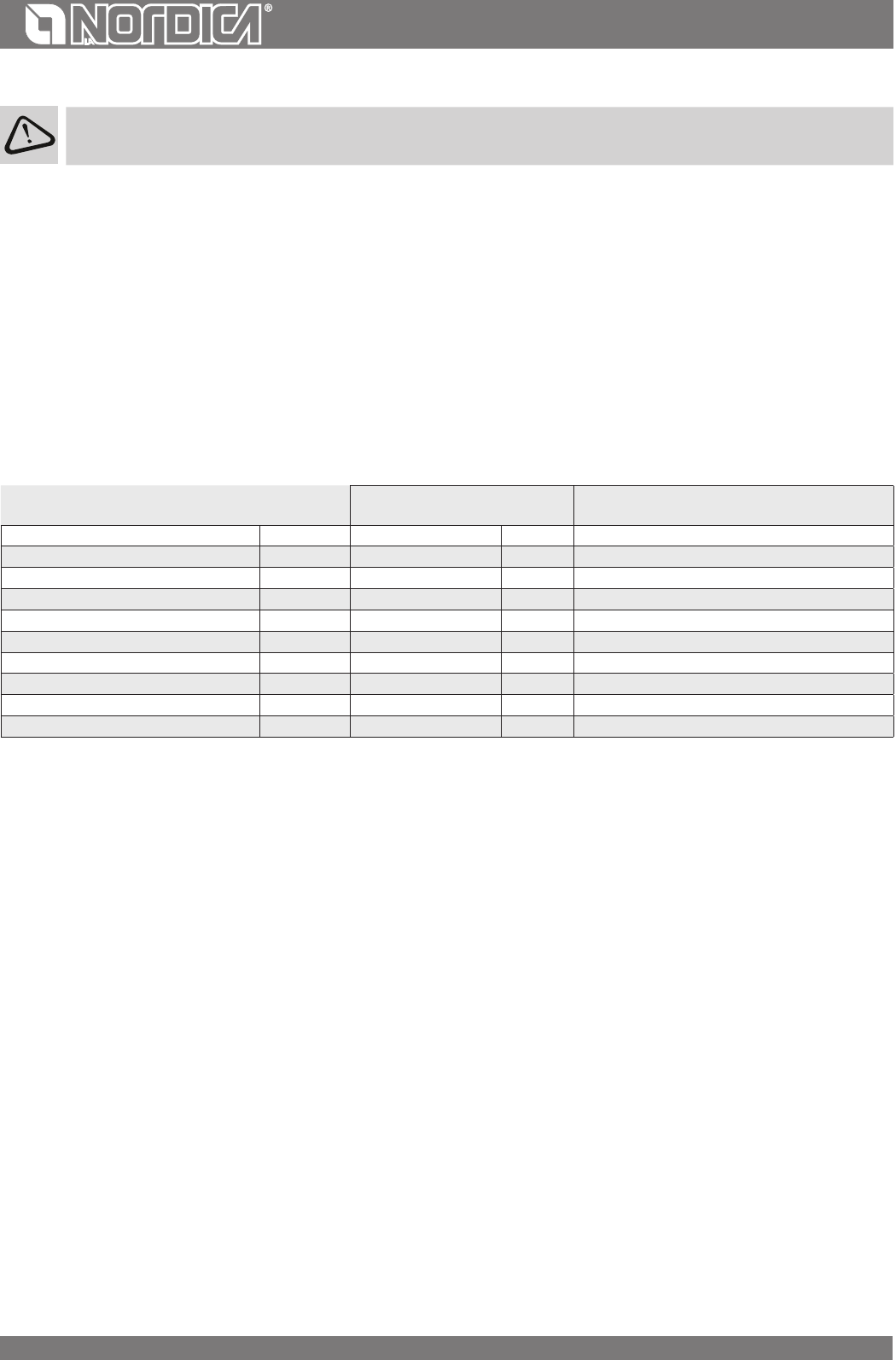
DETERMINAZIONE DELLA POTENZA TERMICA
Non esiste regola assoluta che permetta di calcolare la potenza corretta necessaria. Questa potenza è in funzione dello spazio da riscaldare,
ma dipende anche in grande misura dall’isolamento. In media, la potenza calorica necessaria per una stanza adeguatamente isolata sarà 30
kcal/h al m
3
(per una temperatura esterna di 0 °C).
Siccome 1 kW corrisponde a 860 kcal/h, possiamo adottare un valore di 35 W/m
3
.
Supponendo che desideriate riscaldare una stanza di 150 m
3
(10 x 6 x 2,5 m) in un’abitazione isolata, vi occorreranno, 150 m
3
x 35 W/m
3
= 5250
W o 5,25 kW. Come riscaldamento principale un apparecchio di 8 kW sarà dunque suciente.
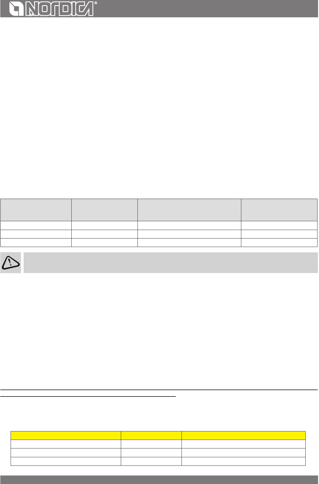
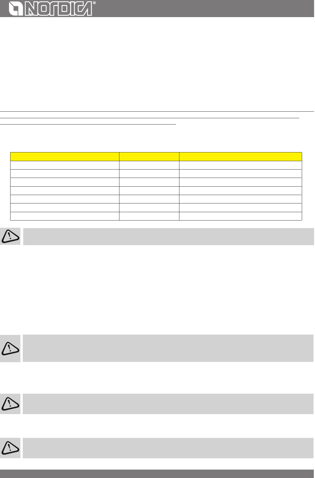
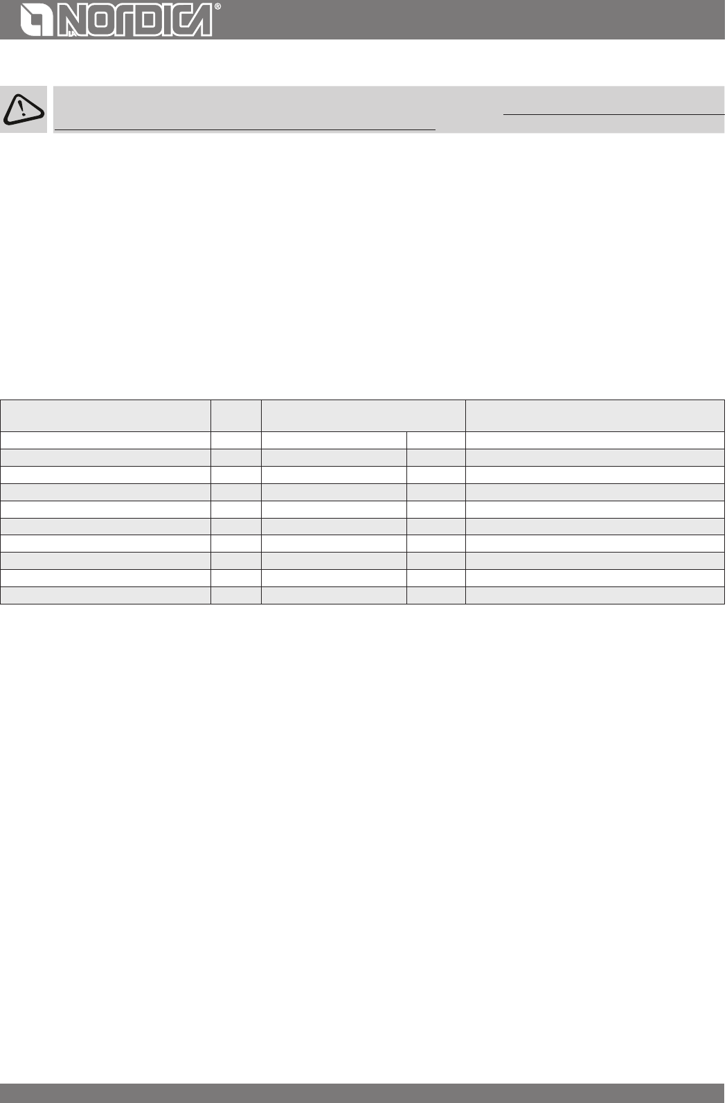
Valore indicativo di combustione
Quantità richiesta in rapporto a
1 kg di legna secca
CarburanteUnitàkcal/hkW
Legna secca (15% di umidità)kg36004.21,00
Legna bagnata (50% di umidità)kg18502.21,95
Bricchette di legnakg40005.00,84
Bricchette di legnitekg48005.60,75
Antracite normalekg77008.90,47
Cokekg67807.90,53
Gas naturalem
3
78009.10,46
NaftaL85009.90,42
ElettricitàkW/h8601.04,19
17
ITALIANO
CONDIZIONI DI GARANZIA
1. I prodotti La Nordica S.p.A. sono garantiti, nell’ambito della comunità europea, per un periodo di 24 mesi dalla data di acquisto.
L’acquisto deve essere provato da un documento scalmente valido rilasciato dal rivenditore (scontrino scale, fattura o bolla di trasporto) che
identichi il prodotto acquistato e la data di acquisto e/o consegna dello stesso.
ATTENZIONE: La presente garanzia convenzionale non sostituisce la garanzia prevista dalle norme europee a tutela dei Consumatori.
La garanzia convenzionale si deve intendere limitata al territorio Italiano ed a quei territori all’interno della Comunità Europea coperti dal
servizio di centri di assistenza tecnica autorizzati (vericare sul sito www.lanordica-extraame.com)
Deve inoltre intendersi delimitata territorialmente allo stato di residenza e/o domicilio del consumatore che deve essere lo stesso ove ha la
sede legale e/o d’aari il venditore del prodotto La Nordica S.p.A.
Le presenti norme non si applicano nei casi di acquisto del prodotto nell’ambito di attività commerciali, imprenditoriali o professionali. In
questi casi la garanzia del prodotto sarà limitata ad un periodo di 12 mesi dalla data di acquisto.
GARANZIA ITALIA
Cosa fare in caso di anomalia nel funzionamento del prodotto:
Consultare il libretto di istruzioni per accertarsi che l’anomalia non possa essere risolta con la corretta applicazione delle funzionalità del
prodotto stesso. Accertarsi che il difetto rientri nella tipologia di anomalie coperte da garanzia; in caso contrario il costo dell’intervento sarà a
completo carico del consumatore. Quando richiedete l’intervento del Servizio Assistenza al Centro di Assistenza Autorizzato indicate sempre:
- natura del difetto - modello del vostro apparecchio - indirizzo completo - numero di telefono
GARANZIA EUROPA
Cosa fare in caso di anomalia nel funzionamento del prodotto:
Consultare il libretto di istruzioni per accertarsi che l’anomalia non possa essere risolta con la corretta applicazione delle funzionalità del
prodotto stesso. Accertarsi che il difetto rientri nella tipologia di anomalie coperte da garanzia; in caso contrario il costo dell’intervento sarà
a completo carico del consumatore. Richiedete l’intervento del Servizio Assistenza o l’indirizzo del centro di assistenza tecnica autorizzato al
venditore indicando sempre: natura del difetto, modello del vostro apparecchio, indirizzo completo e numero di telefono.
Per il difetto di conformità manifestatosi nei primi 6 mesi di vita del prodotto il consumatore ha diritto alla riparazione del difetto senza
alcuna spesa.
Dal settimo al ventiquattresimo mese, nel caso in cui sia stato accertato un vizio di conformità, il consumatore dovrà sostenere il costo
della chiamata mentre il venditore continuerà a farsi carico del costo della manodopera e di eventuali ricambi funzionali utilizzati.
2. Qualora il difetto riscontrato sia riconducibile a condizioni e/o eventi esterni quali, a puro titolo esemplicativo e non esaustivo, portata
insuciente degli impianti; errata installazione e/o manutenzione operata da personale non in possesso dei requisiti previsti dalle leggi in
vigore nel paese di residenza del consumatore; negligenza; incapacità d’uso e cattiva manutenzione da parte del consumatore, rispetto a
quanto riportato e raccomandato nel libretto di istruzioni del prodotto, che costituisce parte integrante del contratto di vendita, decade la
presente garanzia.
Non sono altresì compresi nella presente garanzia i danni subiti dal prodotto in assenza di cause provate imputabili a vizi di fabbricazione.
Allo stesso modo sono esclusi dalla presente garanzia i vizi riconducibili al mancato corretto funzionamento della canna fumaria, ai sensi
della legislazione in vigore nel paese al momento dell’acquisto, così come tutti i difetti del prodotto dovuti ad incuria, rottura accidentale,
manomissione e/o danneggiamento nel trasporto (gra, ammaccature etc.), interventi eseguiti da personale non autorizzato ed ulteriori
danni causati da erronei interventi del consumatore nel tentativo di porre rimedio all’iniziale guasto.
Sono esclusi da garanzia i seguenti materiali di consumo: le guarnizioni, i vetri ceramici o temperati, i rivestimenti e griglie in ghisa, materiali
refrattari ( es. Nordiker o altro), i particolari verniciati, cromati o dorati, gli elementi in maiolica, le maniglie, il braciere ed i relativi componenti.
Nei prodotti Idro lo scambiatore di calore è escluso dalla garanzia nel caso in cui non venga realizzato un adeguato circuito anticondensa che
garantisca una temperatura di ritorno dell’apparecchio di almeno 55 gradi. In generale sono esclusi da garanzia tutti i componenti esterni al
prodotto sui quali il consumatore può intervenire direttamente durante l’uso e/o manutenzione o che possono essere soggetti ad usura, e/o
la formazione di ruggine, macchie su acciaio dovute all’utilizzo di detergenti aggressivi.
In caso di segnalazione di difetti non riscontrati poi in fase di verica da parte di un tecnico autorizzato, l’intervento sarà a completo carico del
consumatore.
3. Qualora il ripristino alla conformità non fosse possibile attraverso la riparazione del prodotto/componente, si provvederà alla sostituzione,
lasciando immutati la scadenza ed i termini di garanzia acquisiti al momento dell’acquisto del prodotto/componente da sostituire.
4. La Nordica S.p.A. declina ogni responsabilità per eventuali danni che possono, direttamente o indirettamente, derivare a persone, animali
e cose, in conseguenza alla mancata osservanza di tutte le prescrizioni indicate nell’apposito libretto istruzioni e concernenti le avvertenze in
tema di installazione, uso e manutenzione del prodotto, scaricabile anche dal sito internet.
5. Sono esclusi dalla garanzia gli interventi per la taratura e/o regolazione del prodotto in relazione al tipo di combustibile o altro.
18
ITALIANO
6.Qualora il Prodotto venisse riparato presso uno dei Centri Assistenza Tecnica Autorizzati indicati dalla La Nordica S.p.A. e nel caso di
sostituzione del prodotto, il trasporto sarà gratuito. Nei casi in cui il tecnico fosse in grado di riparare il prodotto presso il domicilio dell’utente,
è lo stesso si riutasse, il trasporto in laboratorio e la riconsegna saranno invece a suo carico.
7.Trascorso il periodo di 24 mesi di garanzia ogni intervento di riparazione sarà a completo carico del consumatore.
8. In caso di controversie il foro giudiziario esclusivamente competente è il foro della sede legale di La Nordica S.p.A. - (Vicenza-Italia)
ULTERIORI AVVERTENZE
• Utilizzare esclusivamente il combustibile raccomandato dal produttore. Il prodotto non deve essere utilizzato come inceneritore.
• Non utilizzare il prodotto come scala o struttura di appoggio.
• Non mettere ad asciugare biancheria sul prodotto. Eventuali stendibiancheria o simili devono essere tenuti ad apposita distanza dal
prodotto. Pericolo di incendio e danneggiamento del rivestimento.
• Ogni responsabilità per un uso improprio del prodotto è totalmente a carico dell’utente e solleva il produttore da ogni responsabilità
civile e penale.
• Qualsiasi tipo di manomissione o di sostituzione non autorizzata di particolari non originali del prodotto può essere pericoloso per
l’incolumità dell’operatore e sollevano la ditta da ogni responsabilità civile e penale.
• Gran parte delle superci del prodotto sono molto calde (porta, maniglia, vetro, tubi uscita fumi, ecc.). Occorre quindi evitare di entrare
in contatto con queste parti senza adeguati indumenti di protezione o appositi mezzi, come ad esempio guanti a protezione termica
• E’ vietato far funzionare il prodotto con la porta aperta o con il vetro rotto.
• Il prodotto deve essere connesso elettricamente ad un impianto munito di un ecace sistema di messa a terra.
• Spegnere il prodotto in caso di guasto o cattivo funzionamento.
• Non lavare il prodotto con acqua. L’acqua potrebbe penetrare all’interno dell’unità e guastare gli isolamenti elettrici, provocando
scosse elettriche.
• Le installazioni non rispondenti alle norme vigenti fanno decadere la garanzia del prodotto, così come l’uso improprio e la mancata
manutenzione come prevista dal costruttore.
19
ENGLISH
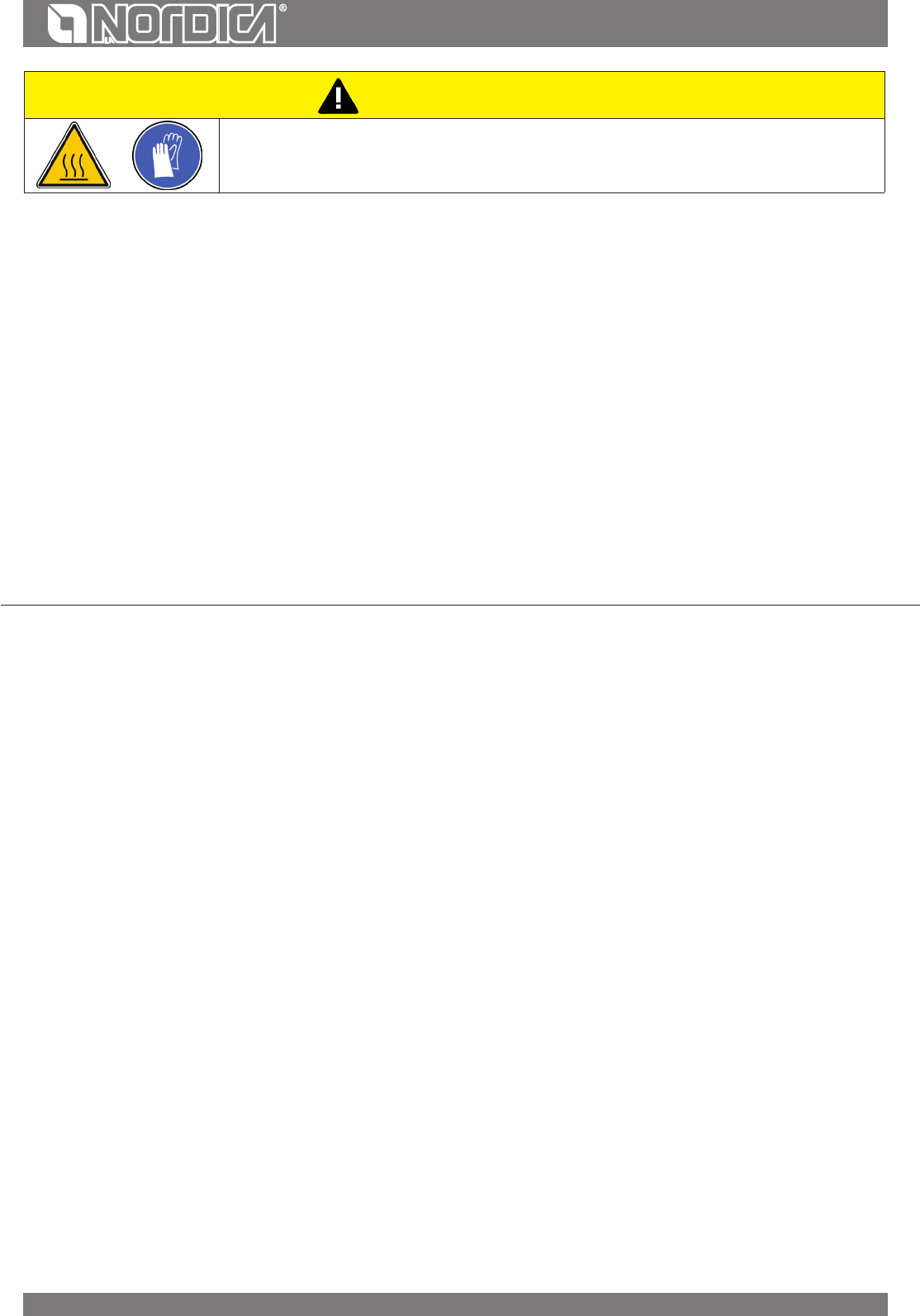
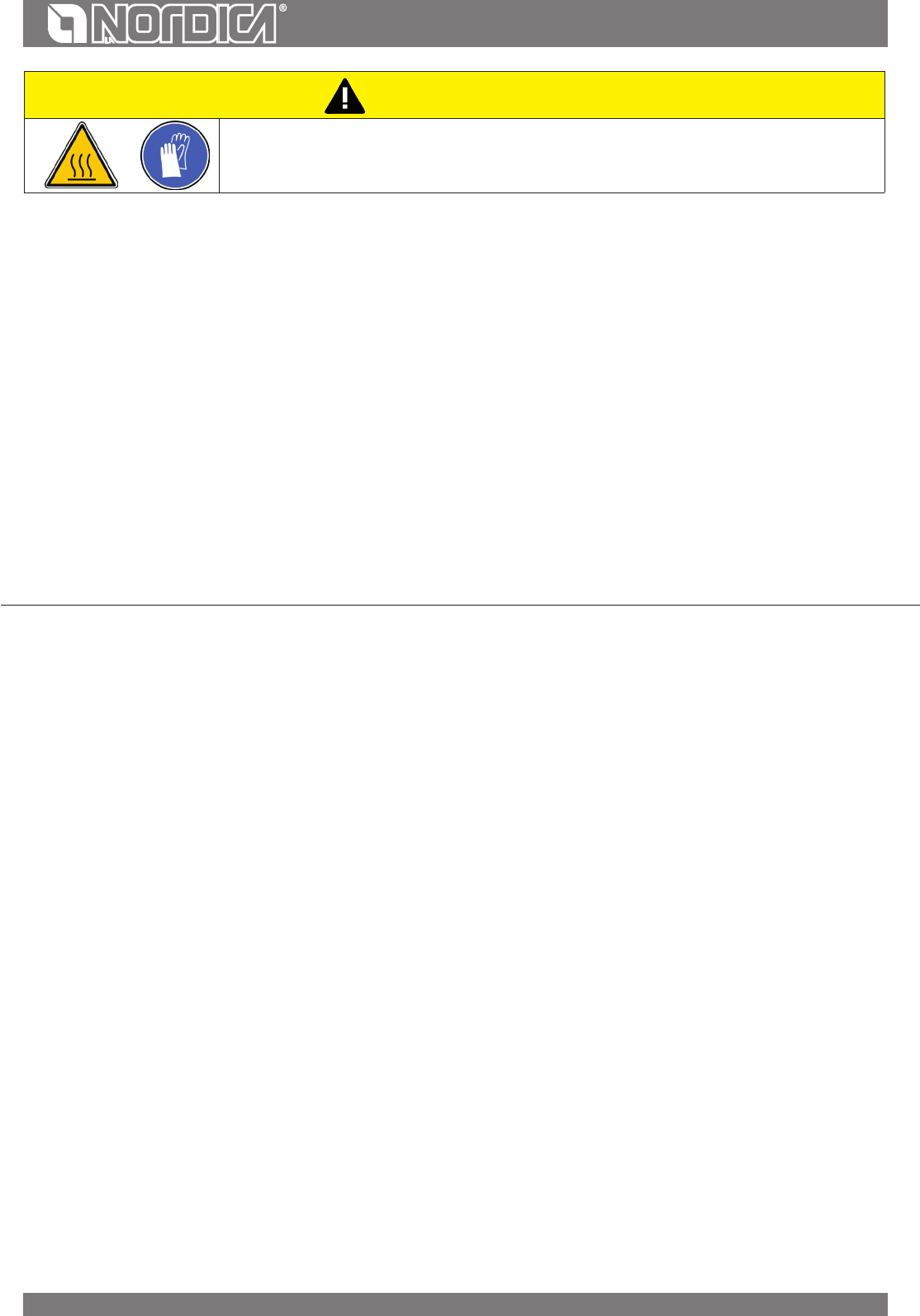
ATTENTION
SURFACES CAN BECOME VERY HOT!
ALWAYS USE PROTECTIVE GLOVES!
During combustion, thermal energy is released that signicantly increases the heat of surfaces, doors, handles, controls, glass, exhaust
pipes, and even the front of the appliance. Avoid contact with those elements if not wearing protective clothing (protective gloves
included). Make sure children are aware of the danger and keep them away from the stove during operation.
GENERAL PRECAUTIONS................................................................................................................................................................................22
DECLARATION OF CONFORMITY OF THE MANUFACTURER ...................................................................................................................... 22
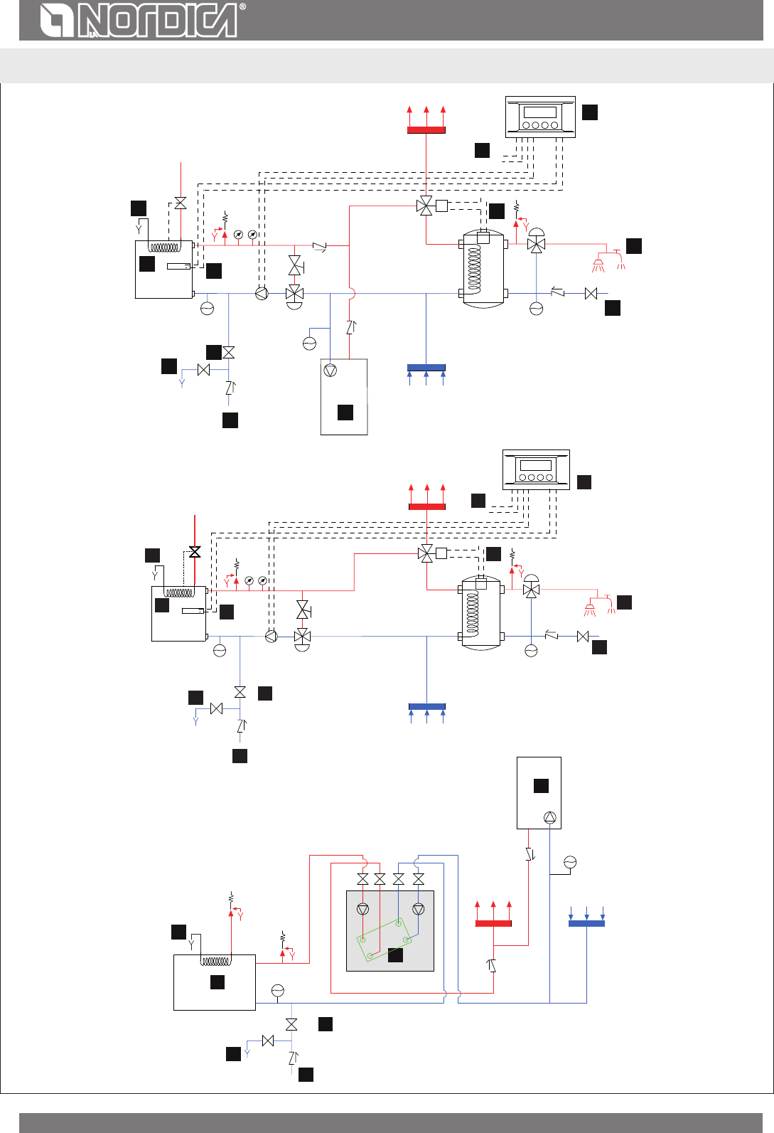
OPEN EXPANSION TANK SYSTEM ...........................................................................................................................................................................................................................................23
CLOSED EXPANSION TANK SYSTEM ......................................................................................................................................................................................................................................24
VMA ANTICONDENSATION MIXING VALVE IT IS MANDATORY PURCHASED AS OPTIONAL ................................................................................................................24
SYSTEM CONNECTION AND FILLING ....................................................................................................................................................................................................................................25
CONNECTION TO THE FLUE ......................................................................................................................................................................................................................................................27
AIR FOR COMBUSTION ...............................................................................................................................................................................................................................................................27
VENTILATION AND AERATION OF THE INSTALLATION PREMISES .............................................................................................................................................................................28
ALLOWED / NOT ALLOWED FUELS ................................................................................................................................................................28
LOW EMISSION FIRE LIGHTING ...............................................................................................................................................................................................................................................30
NORMAL OPERATION .....................................................................................................................................................................................30
ELECTRICAL POWER SUPPLY FAILURE ..................................................................................................................................................................................................................................30
OPERATION DURING TRANSITION PERIODS ......................................................................................................................................................................................................................31
SUMMER USE ..................................................................................................................................................................................................................................................................................31
MAINTENANCE AND CARE .............................................................................................................................................................................31
CLEANING OUT THE ASHES ......................................................................................................................................................................................................................................................32
CLEANING THE FLUE ....................................................................................................................................................................................................................................................................32
MAINTENANCE OF THE EXTENSIBLE GUIDES ....................................................................................................................................................................................................................32
MAINTENANCE ON THE WATER SYSTEM .............................................................................................................................................................................................................................33
CALCULATION OF THE THERMAL POWER ....................................................................................................................................................33
THERMOSTATIC VALVE VAST TECHNICAL DATA SHEET .................................................................................................................................................................................................90
TECHNICAL DATA SHEET. ...............................................................................................................................................................................98
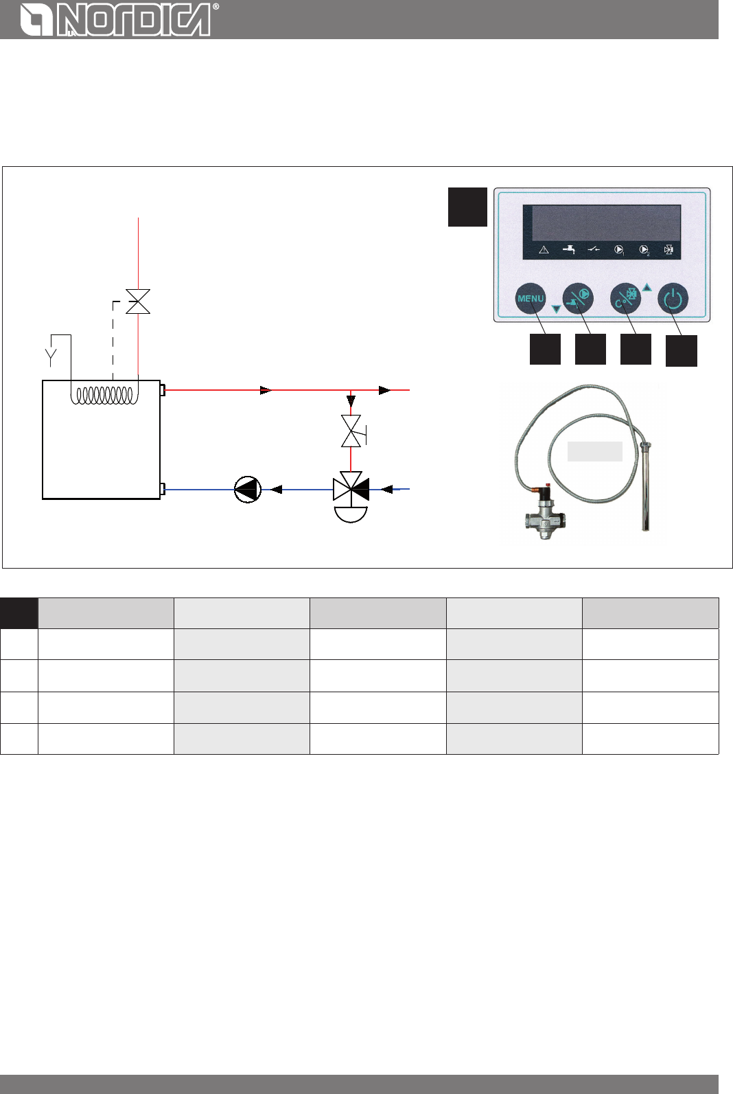
Solid fuel thermo products must be installed with safety devices determined by laws in vigour.
For this reason the thermo products is equipped with a heat discharge coil.
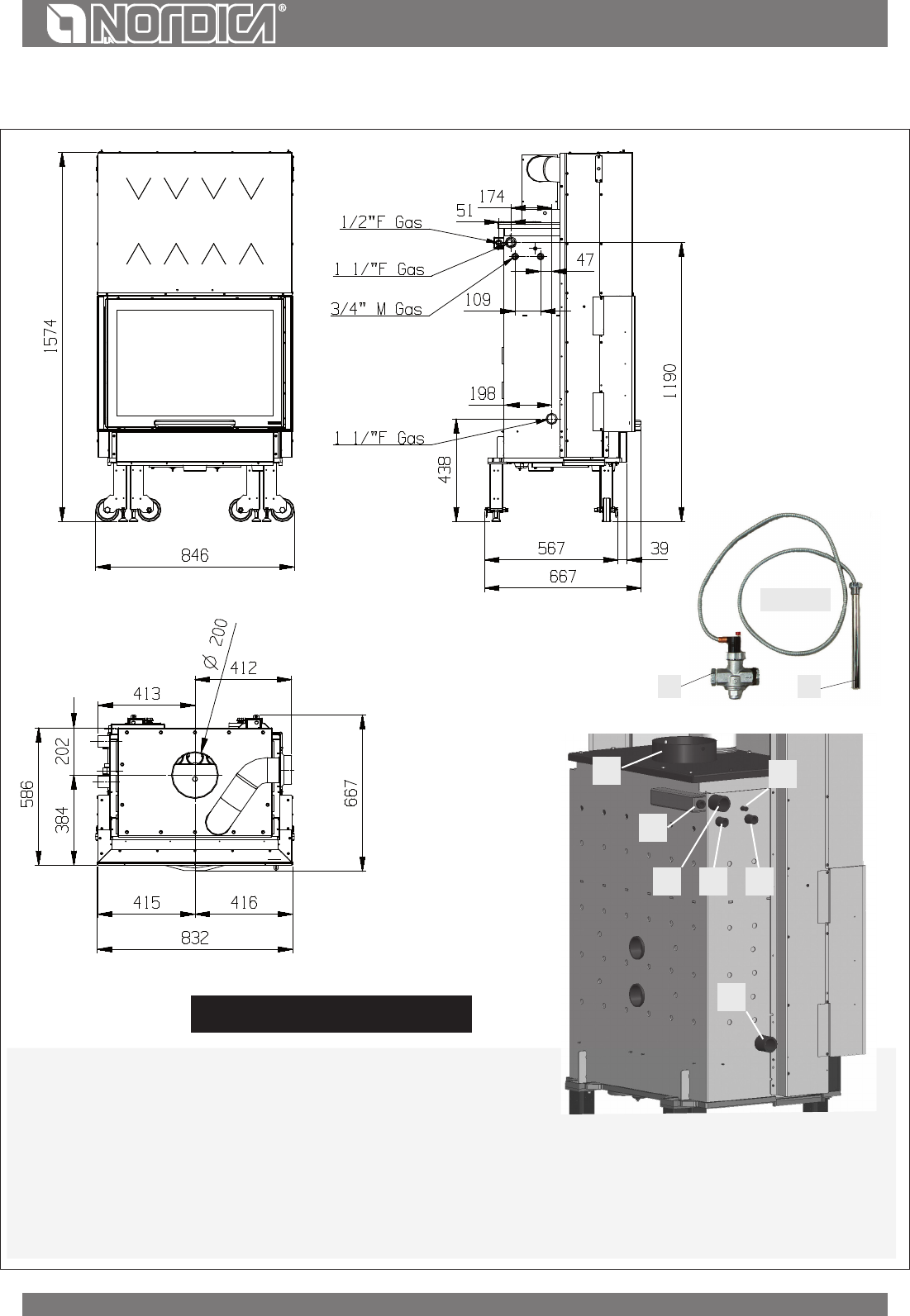
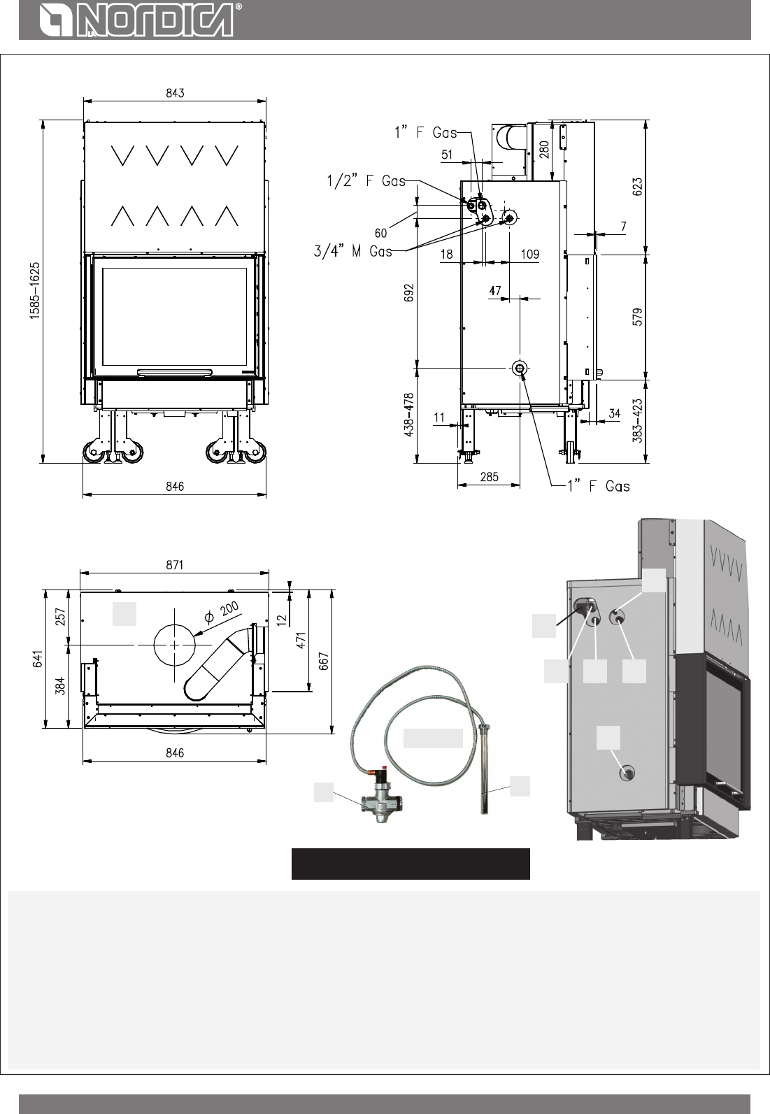
The heat discharge coil must have one side connected to the water network (chapter INSTALLATION LAY-OUT - chap. DIMENSION SHEET- A
) and the other rot drainage network (C). When the safety temperature is reached, the automatic thermal discharge valve DSA, the bulb of
which is to be connected to attachment B, enables the intake of cold water in the boiler coil, discharging the excess heat out of pipe C towards
a conveniently installed drain. Cooling circuit upstream pressure must be at least 1,5 bar.
WARNING: We cannot be made liable for a wrong operation of the plant, when it does not comply with the provisions of
these instructions or when it uses additional products not suitable for this device(see chapter Thermostatic Valve VAST
TECHNICAL DATA SHEET).
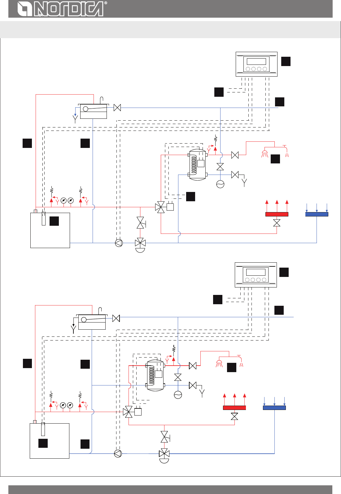
SYSTEM CONNECTION AND FILLING
Some examples, purely indicative of the installation, are reported at chapter INSTALLATION LAY-OUT, while the connections to the
thermoproduct are reported at chapter DIMENSIONS.
ATTENTION: The lling of the system must take place exclusively by the natural fall of the water from the open expansion
tank through the feed pipe in order to avoid that a too high water system grid pressure could change or cause the explosion
of boiler body.
During this phase, open all the bleed valves of the radiators to prevent the formation of air sacks, checking the outlet of water to avoid
unpleasant oodings.
The watertight test of the installation is performed with the pressure of expansion tank open.
The installation must always be full of water even when the thermo-product is not used. During winter season the non use
has to be faced by adding antifreeze substances.
FIREFIGHTING SAFETY MEASURES
When installing the appliance, the following safety measures must be observed:
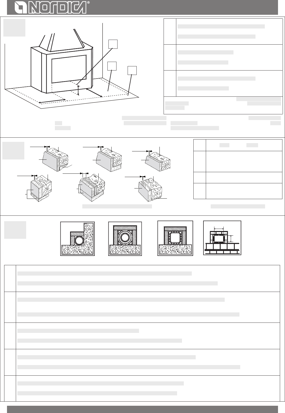
a) In order to ensure sucient thermal insulation, respect the minimum safety distance from objects or furnishing components ammable
and sensitive to heat and from materials with ammable structure (see CE MARKING INFORMATION - Picture 7). All the minimum
safety distances are shown on the product data plate and lower values must not be used.
b) in front of the furnace door, in the radiation area, there must be no ammable or heat-sensitive objects or material at a distance of less
than 120 cm. This distance can be reduced to 40 cm where a rear-ventilated, heat-resistant protection device is installed in front of the
whole component to protect;
c) If the product is installed on a no totally refractory oor, one must foresee a reproof background. The oors made of inammable
material, such as moquette, parquet or cork etc., must be covered by a layer of no-inammable material (size according to regional
law, see Picture 1).
The ash drawer must always be inserted when the appliance is in operation.
The solid combustion residues (ashes) must be collected in a metal container that is hermetically sealed and re resistant. The appliance must
never be lit in the presence of gaseous emissions or vapours (for example: glue for linoleum, petrol, etc,). Do not place ammable materials in
the vicinity of the appliance.
During the combustion, thermal air is emitted by involving the heating of areas, door and glass hearth, of the door handles or
controls, of the smokes pipe and, in case, of the front part of appliance. Avoid to touch those parts without a protective clothing
or without accessory tools (gloves resistant to heat, control devices). Ensure children are aware of these dangers and keep
them away from the furnace when it is on.Warn children that the device becomes very hot and that it must not be touched.
When using the wrong fuel or one which is too damp, due to deposits present in the ue, a ue re is possible.
FIRSTAID MEASURES
Should any re arise in the stack or in the ue:
a) Close the feeding door.
b) Close the registers of combustion air
c) Extinguish the re using carbon dioxide re-ghting means (CO
2
dust).
d) Seek immediate intervention of FIRE BRIGADE.
DO NOT EXTINGUISH FIRE USING WATER JETS. When the ue does not burn any more please arrange an examination by a specialist in order
to nd possible cracks and permeable points.
BEAM PROTECTIONS
Considering the irradiation of the hearth, it is necessary to be particularly careful in protecting the beams while designing your stack. Consider
the proximity of beams to the external surfaces of the hearth, on one side, and the irradiation of the glass door, usually very close to the beams,
on the other side. In any case, it has to be considered that the internal or lower surfaces of this beam in ammable material must not come in
contact with temperatures higher than 65 °C. Picture 2 gives some examples of execution.
WARNING: We cannot be made liable for a wrong operation of the plant, when it does not comply with the provisions of
these instructions or when it uses additional products not suitable for this device.
25
ENGLISH
DESCRIPTION
Denition: thermo-replace according to EN 13229.
La NORDICA thermo-replace are ideal for holiday ats and weekend houses or as auxiliary heating all year round. Wooden logs are used as
fuel. The appliance works as an intermittent operating appliance.
The appliance is composed of painted and galvanised sheet steel and cast iron.
The replace is found inside the boiler, is built in 4 mm thick steel and is reinforced using welded nails. The water in the heating system
circulates in the boiler, which absorbs the heat produced in the replace. A swivelling, removable grid is found inside the replace (Picture 12
pos. A). Ash drawer (Picture 12 pos. B).
The sight door is assembled on extensible ball guides, which assure a robust and silent operation reliable in time. The door lifting counter-
weight is supported by two sturdy chains with related pinions.
The ceramic glass window (resistant up to 700°C) of the door provides a lovely view of the burning ames and prevents sparks and smoke
from getting out.
ACCESSORIES
POKERGLOVE
WF25 - WF25X - WF25 PlusSERIESSERIES
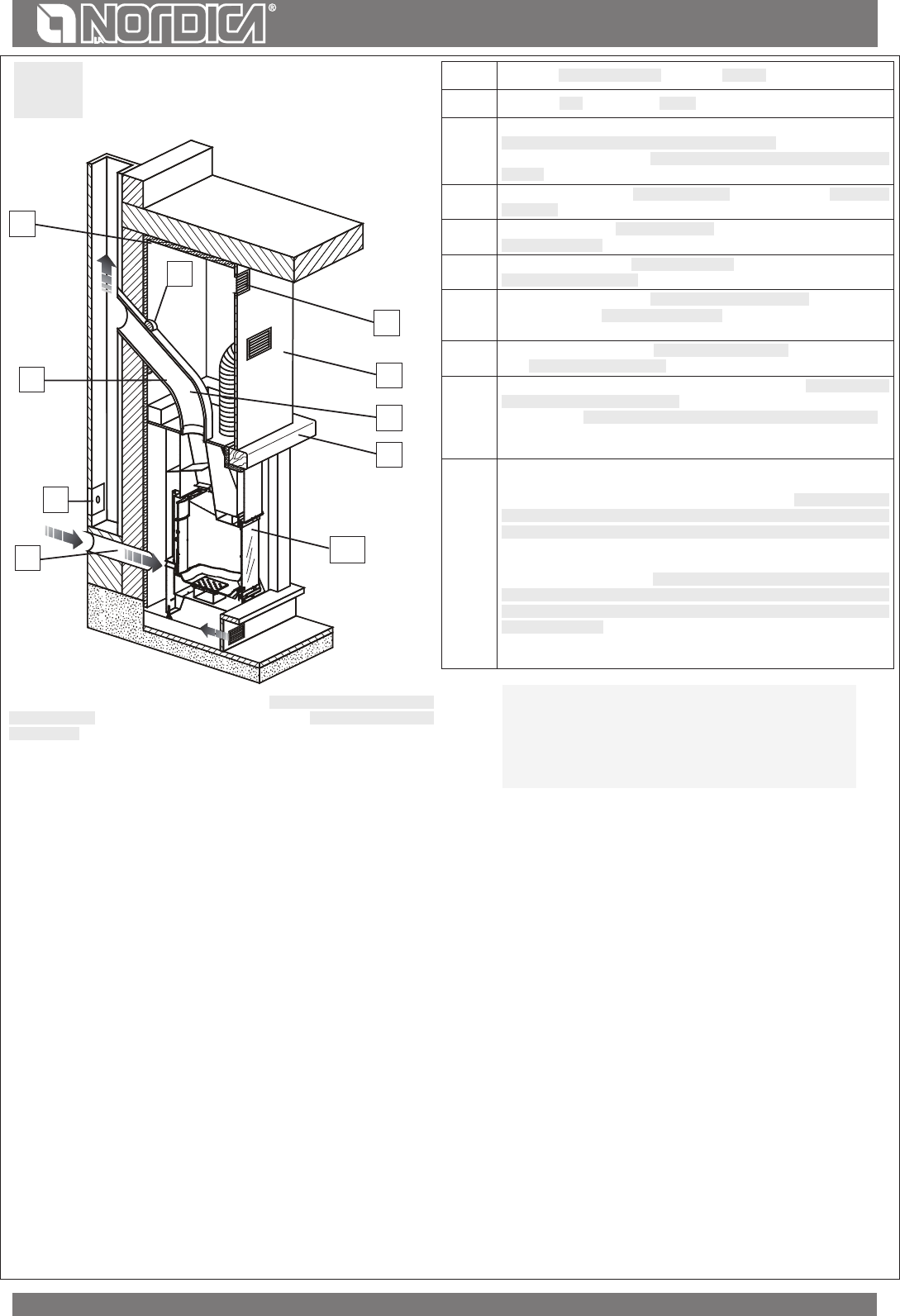
Room heating takes place:
a) by radiation: the heat is radiated into the environment through the panoramic window and the hot external surfaces of the thermo-
replace;
b) by conduction: radiators or heat convectors of the centralised system fed by hot water produced by the boiler.
The device is equipped with registers of primary and secondary air, with which it is possible to adjust the combustion air.
1A- PRIMARY air register (Picture 8)
With the air register located under the door of the hearth, it is possible to adjust the air ow through the ash drawer and the grating
in direction of the fuel. The primary air is necessary for the combustion process. In order to open the air ow, the bar must be
completely pulled out. The ash drawer has to be emptied regularly, so that ash cannot hinder the intake of primary air for the
combustion. Primary air is also necessary to keep re live.
The primary air register must be almost completely closed during wood combustion, as otherwise the wood burns too quickly and
the thermo-product may overheat.
2A- SECONDARY air register (Picture 8)
When the bar is pushed to the back the passage of the secondary is completely open.
The secondary air, passing through the two lateral jambs of the front side, heats itself starting the double combustion and keeping at the
same time the glass clean (with open register).
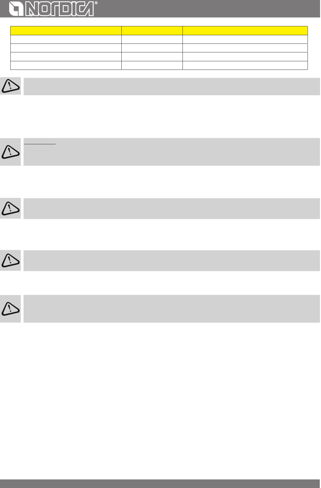
The adjustment of the registers necessary to reach the rated caloric yield is the following one:
Hourly consumption ( kg/h )PRIMARY air SECONDARY air TERTIARY AIR
WF25 11Figura 8 C CLOSEDFigura 8 C OPENPREADJUSTED
WF25 X8Figura 8 C CLOSEDFigura 8 C OPENPREADJUSTED
WF25 Plus5,4Figura 8 C CLOSEDFigura 8 C OPENPREADJUSTED
FLUE
Essential requirements for a correct operation of the device:
• the internal section must be preferably circular;
• be thermally insulated and water-proof and produced with materials suitable to resist to heat, combustion products and
possible condensates;
• not be throttled and show a vertical arrangement with deviations not greater than 45°;
• if already used, it must be clean;
• all the sections of the ue gas duct must be accessible to inspection;
• inspection openings must be provided for cleaning.
• observe the technical data of the instructions manual;
Should the ues have a square or rectangular section, internal edges must be rounded with a radius not lower than 20 mm. For the rectangular
section, the maximum ratio between the sides must be = 1.5.
A too small section causes a decrease of the draught. It is suggested a minimum height of 4 m.
The following features are FORBIDDEN and therefore they endanger the good operation of the device: asbestos cement, galvanized steel,
rough and porous internal surfaces. In Picture 3 gives some examples of execution.
For a correct installation please respect the sections/lengths of the ue shown in the technical data table. By installations
with dierent dimensions the ue must be suitably sized in accordance with EN13384-1.
The draught created by the ue must be sucient, but not excessive.
A too big ue section can feature a too big volume to be heated and consequently cause diculties in the operation of the device; to avoid
this, tube the ue along its whole height. A too small section causes a decrease of the draught.
26
ENGLISH
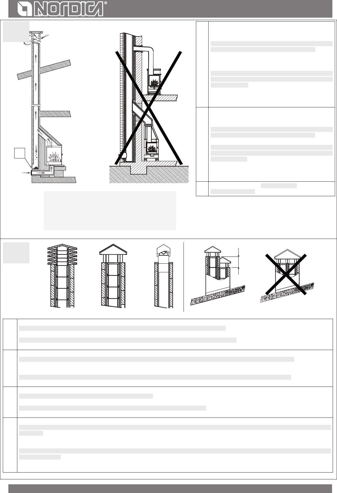
ATTENTION: as far as concern the realisation of the ue connection and ammable materials please follow the requirements
provided by UNI 10683 standard. The ue must be properly spaced from any ammable materials or fuels through a proper
insulation or an air cavity.
It is FORBIDDEN to let plant piping or air feeding channels pass in the same ue. Moreover, it is forbidden to create movable or
xed openings on the same for the connection of further other devices (Picture 4).
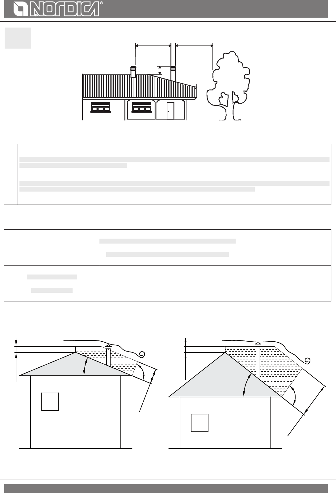
CHIMNEY CAP
The draught of the ue depends also on the suitability of the chimney cap.
Therefore, if it is handicraft constructed, the output section must be more than twice as big as the internal section of the ue (Picture 5).
Should it be necessary to exceed the ridge of the roof, the chimney cap must assure the discharge also in case of windy weather (Picture 6).
The chimney cap must meet the following requirements:
• have internal section equivalent to that of the stack.
• have a useful output section twice as big as the ue internal one.
• be manufactured in such a way as to prevent the penetration of rain, snow, and any other foreign body in the ue.
• be easily checkable, for any possible maintenance and cleaning operation
CONNECTION TO THE FLUE
The connection to the stack must be performed with sti pipes in steel comply with all current Standards and Regulations and to those
envisioned by the law.
It is FORBIDDEN to use metallic pipes or pipes in asbestos cement since they jeopardize the safety of the tting itself,
considering that they are subject to tears or breaks resulting in leaks of smoke.
The exhaust pipe must be air-tight fastened to the stack and can have a maximum inclination of 45°; this to avoid excessive deposits of
condensate produced in the initial start-up phases and/or the excessive gripping of soot and moreover it avoids the slowing down of the
smokes at output.
The failed tightness of the connection can cause the malfunction of the device.
The internal diameter of the connection pipe must be equal to the external diameter of the smokes stub pipe of the device. This is assured
by the pipes complying with DIN 1298.
The chimney pressure (DRAUGHT) must be at least 12 Pascal (=1.2 mm of column of water).
The measurement has always to be carried out with hot device (rated thermal performance).
When the depression exceeds 17 Pa (=1.7 mm of column of water), it is necessary to reduce the same by installing an additional draught
regulator (buttery valve) on the exhaust pipe or in the chimney, according to the regulations in force.
IMPORTANT: When using metallic pipes, they must be insulated with proper materials (coatings in insulating bers resistant
up to 600°C) in order to avoid deterioration of walls or of the counter-hood.
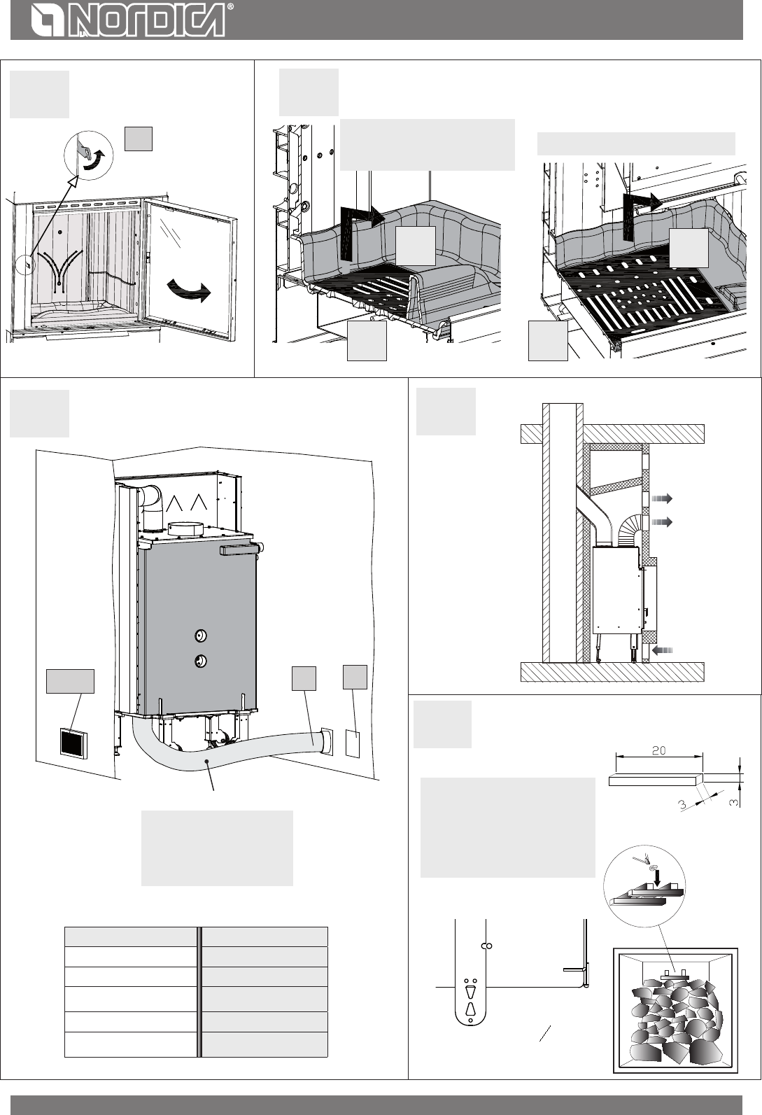
AIR FOR COMBUSTION
It is necessary to ventilate continuously the space included between the upper part, the sides of the device and the deector of the re-
proong material of the hood.
For this reason, it is necessary to foresee an intake of air from the bottom (intake of fresh air) and a high output (output of hot air). The
spaces foreseen for the circulation of air indicated in Picture 7 - Picture 14 represent the minimum requirements:
Top: Minimum opening 800 cm
2
Base: Minimum opening 600 cm
2
In this way, the following targets are achieved:
• a greater safety
• an increase of the heat created by air circulation around the device
• a better working of the appliance
The heat vent grating (Picture 7 pos. 6) has to be installed on the upper part of the hood at about 20 cm from the roof. This must
always be installed since its function is that of letting the heat collected within the hood (overpressure) ow out into the room.
ATTENTION: We recommend making the counterplate in re-retardant plasterboard with self-supporting metal frame, so that its
weight does not bear on the aesthetic covering (marble). We recommend providing an inspection door on the counter plate or
elsewhere as suitable to provide easy accessibility and visibility of the safety devices (pressure gauges, valves,..).
27
ENGLISH
VENTILATION AND AERATION OF THE INSTALLATION PREMISES
As the product draw their combustion air from the place of installation, it is MANDATORY that in the place itself, a sucient quantity of air is
introduced. If windows and doors are airtight (e.g. built according to energy saving criteria), it is possible that the fresh air intake is no longer
guaranteed and this jeopardises the draught of the appliance and your health and safety.
IMPORTANT: For a better comfort and corresponding oxygenation of environment, the combustion air can be directly withdrawn at the
outside through a junction which is to be connected with a exible pipe. The connection pipe (not furnished) must be at with a minimum
diameter of Picture 13, a maximum length of 4 m and with no more than 3 bends. If there is a direct connection with the outside it must be
endowed with a special windbreak.
There MANDATORY be sucient quantity of air for combustion and re-oxygenation of the room to ensure the device will work properly.
There should therefore be vents letting air in from outside the building and enabling circulation of air for combustion even when the doors
and windows are closed.
The air inlets must meet the following requirements:
• they must be protected with grids, metal mesh, etc., but without reducing the net useful section;
• they must be made so as to make the maintenance operations possible;
• positioned so that they cannot be obstructed;
• Any extractor hoods in the room where the device is installed must not operate at the same time as this could cause smoke to enter the
room, even with the replace’s door closed.
The clean and non-contaminated air ow can also be obtained from a room adjacent to that of installation (indirect aeration and ventilation),
as long as the ow takes place freely through permanent openings communicating with the outside.
The adjacent room cannot be used as a garage, or to store combustible material or for any other activity with a re hazard, bathroom, bedroom
or common room of the building.
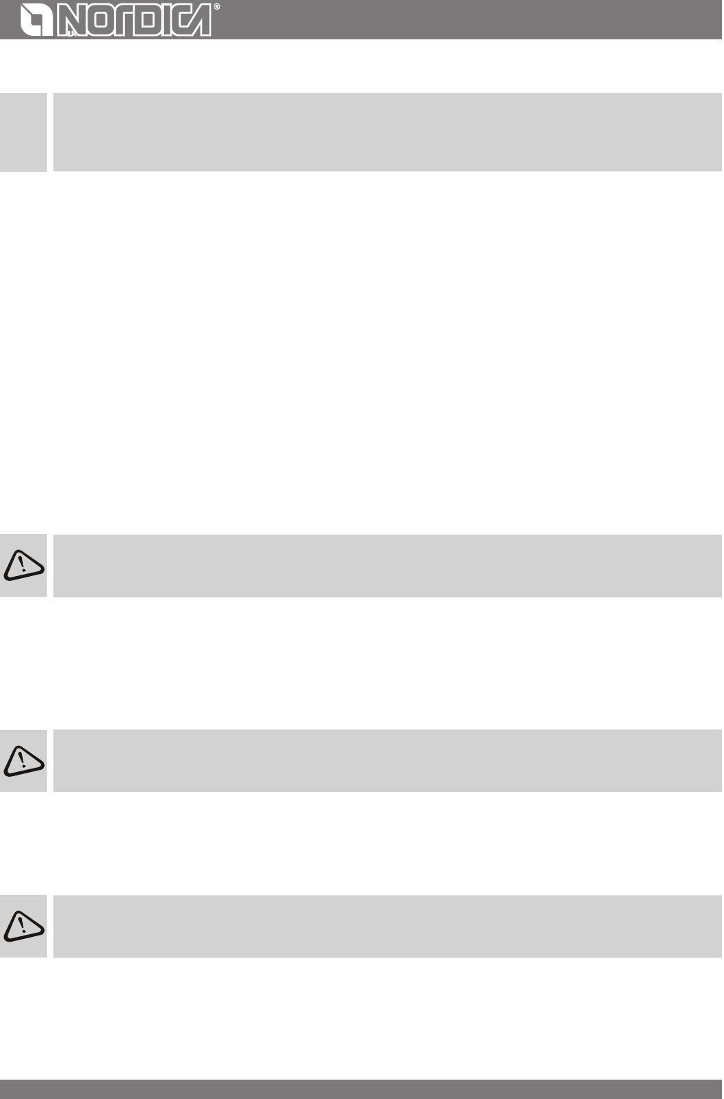
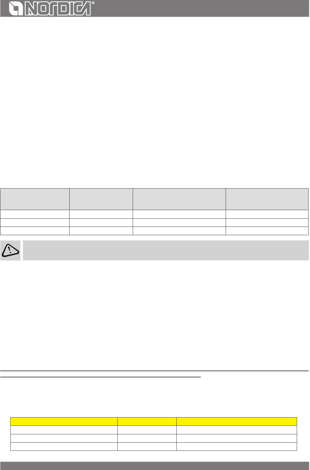
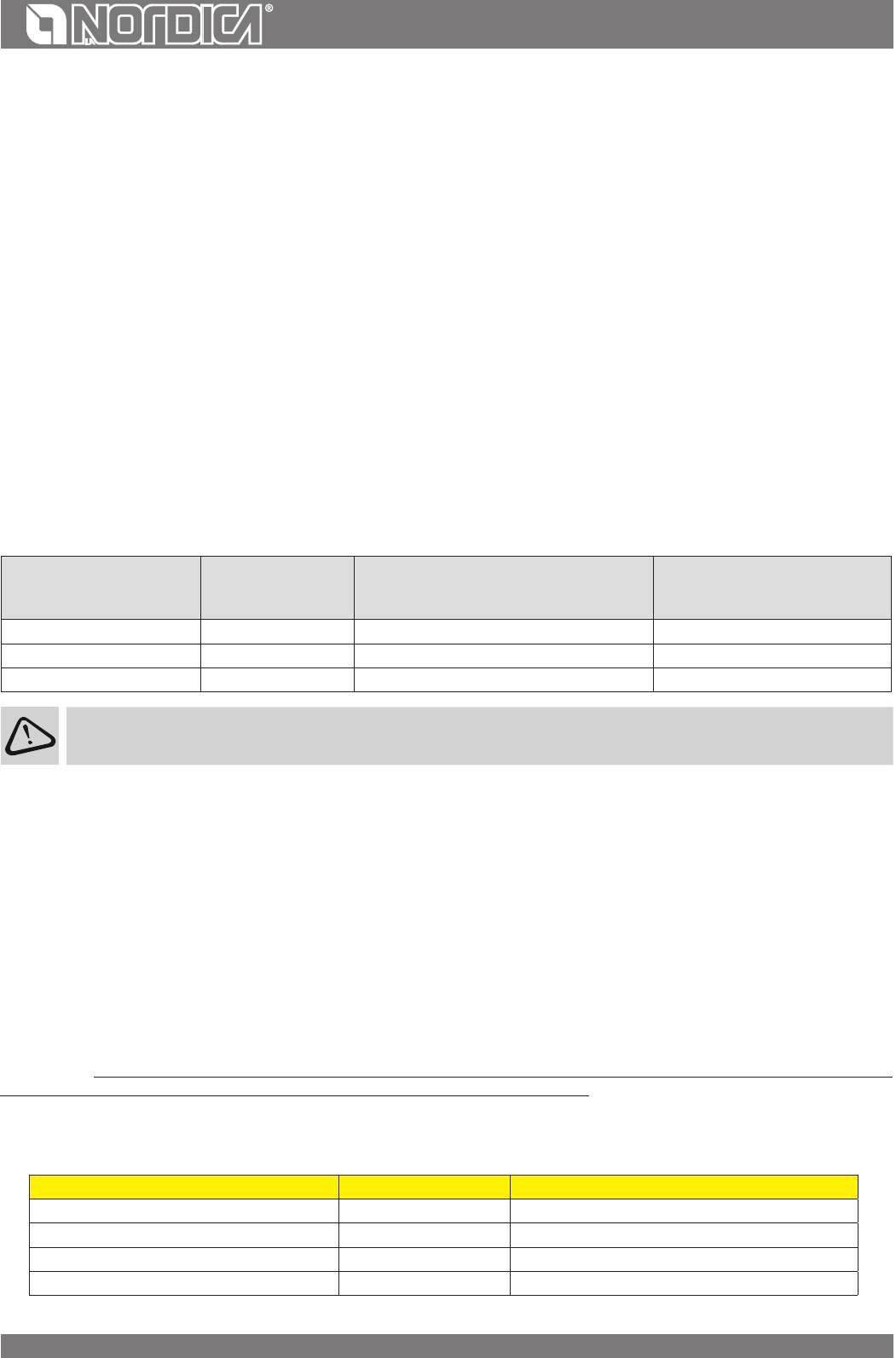
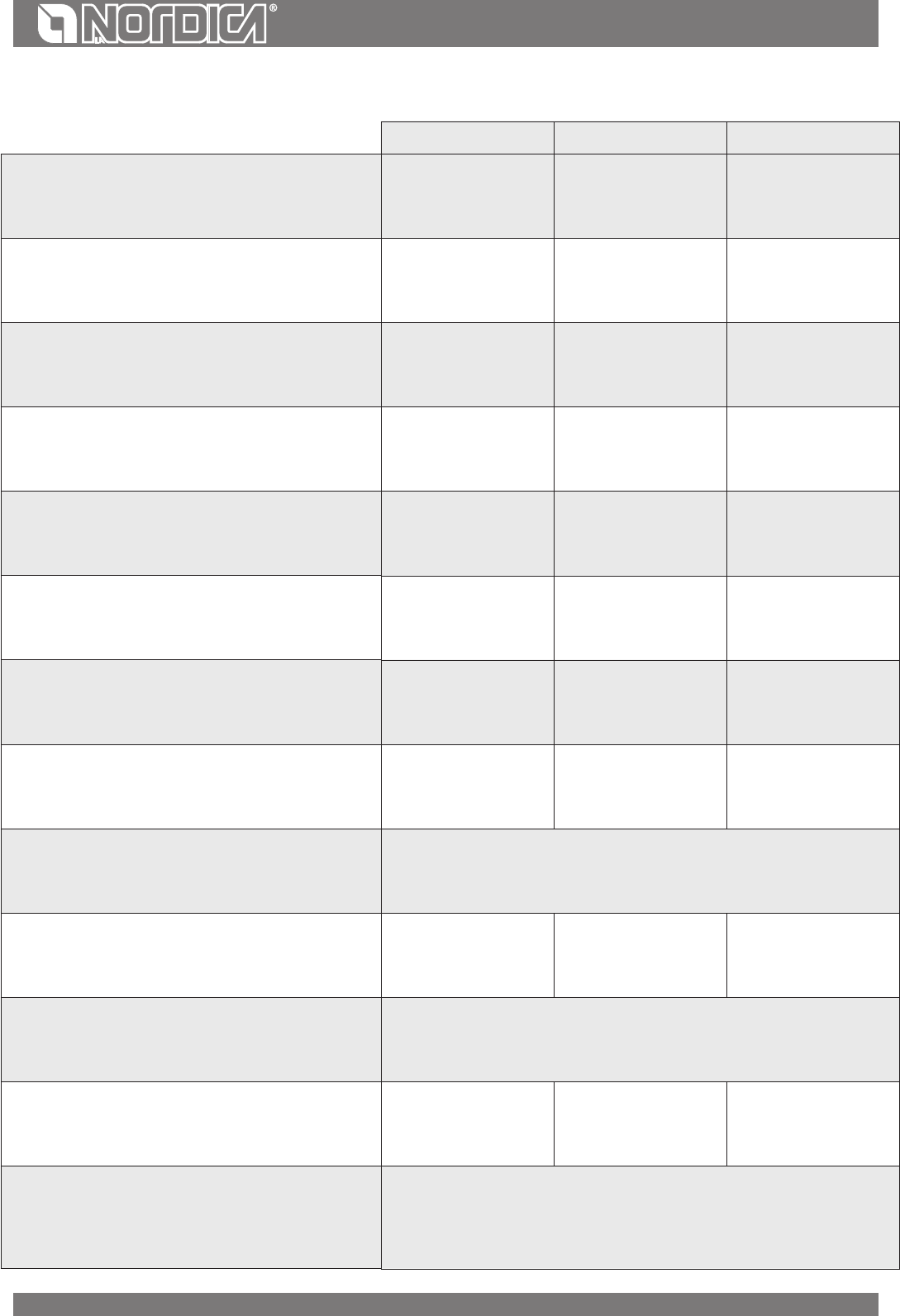
Ventilation is deemed sucient when the room is equipped with air inlets according to the table:
Appliance categoriesReference standard
Percentage of the
net opening section with respect to
the appliance fumes outlet section
Minimum net opening value of
the ventilation duct
FireplacesUNI EN 1322950%200 cm²
StovesUNI EN 1324050%100 cm²
CookersUNI EN 1281550%100 cm²
Installation in premises with re hazards is forbidden. Installation in residential premises in which, in any case, the depression
measured during installation between the internal and external environment is greater than 4 Pa - reference for Italy according to
standard UNI10683.
All national, regional, provincial and municipal laws and standards in force in the country where the appliance is installed must be complied
with.
ALLOWED / NOT ALLOWED FUELS
Allowed fuels are logs. Use exclusively dry logs (max. content of water 20%). Maximum 3 logs should be loaded. The pieces of wood
should have a length of ca. 20-30 cm and a maximum circumference of 30-35 cm.
Compressed not worked-out wood briquettes must be used carefully to avoid overheating that may damage the device,
since these have a very high caloric value.
The wood used as fuel must have a humidity content lower than the 20% and must be stored in a dry place. Humid wood tends to burn
less easily, since it is necessary a greater quantity of energy to let the existing water evaporate. Moreover, humid content involves
the disadvantage that, when temperature decreases, the water condensates earlier in the hearth and therefore in the stack causing
a remarkable deposit of soot with following possible risk of re of the same.
Fresh wood contains about 60% of H
2
O, therefore it is not suitable to be burnt.
It is necessary to place this wood in a dry and ventilated place (for example under a roong) for at least two years before using it.
Besides others, it is not possible to burn: carbon, cuttings, waste of bark and panels, humid wood or wood treated with
paints, plastic materials; in this case, the warranty on the device becomes void.
Paper and cardboard must be used only to light the re.
The combustion of waste is FORBIDDEN and would even damage the appliance and the ue, causing health damages and claims
by the neighborhood owing to the bad smell.
The wood is not a fuel which allows a continuous operation of the appliance, as consequence the heating all over the night is not
possible.
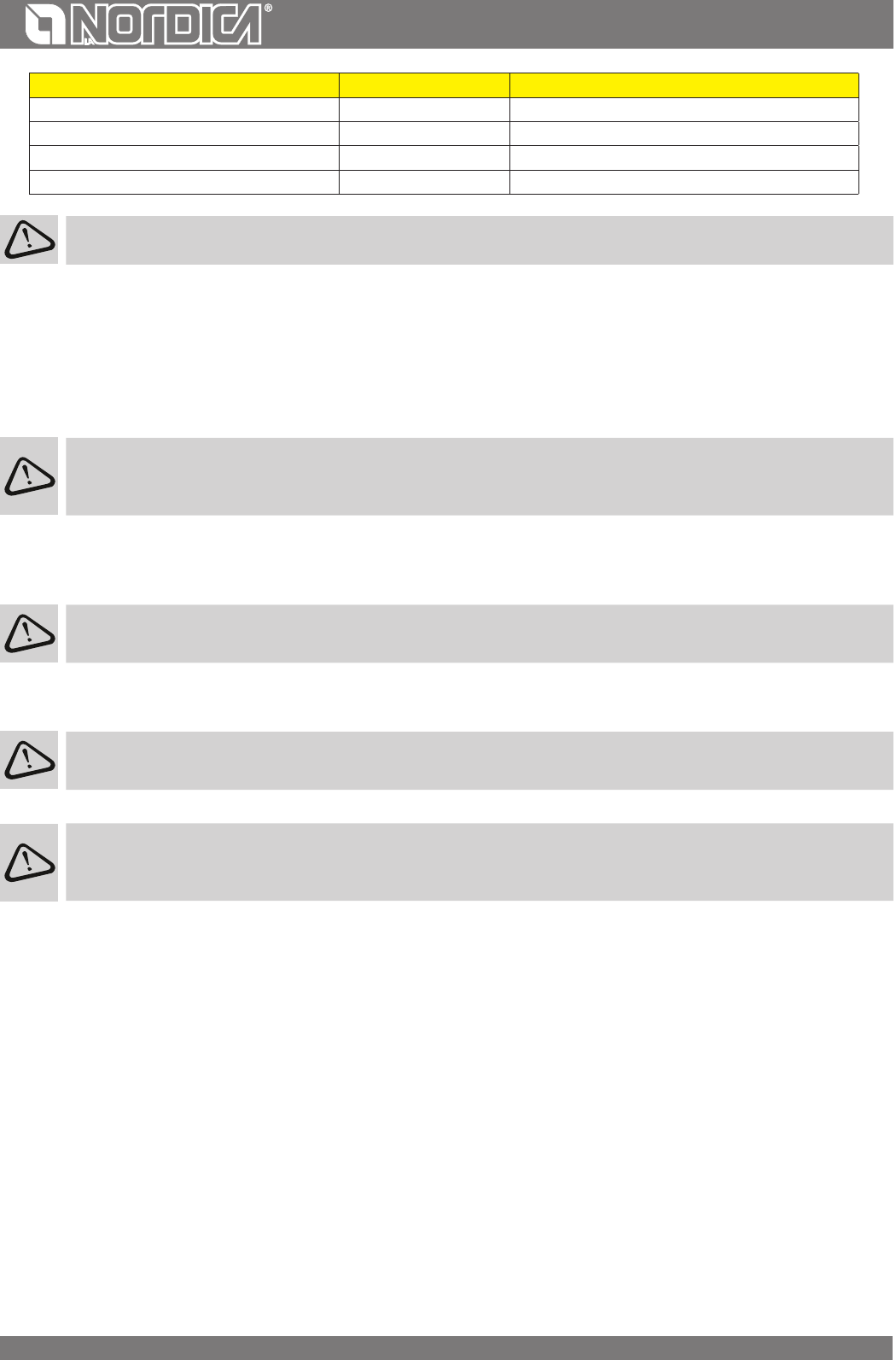
Varietykg/mckWh/kg moistness 20%
Beech
7504,0
Oak
9004,2
Elm
6404,1
28
ENGLISH
Varietykg/mckWh/kg moistness 20%
Poplar
4704,1
Larch*
6604,4
Spruce*
4504,5
Scots pine *
5504,4
* RESINOUS WOOD NOT SUITABLE FOR THE BURNING
ATTENTION : the continuous and protracted use of aromatic wood (eucalyptus, myrtle etc.) quickly damages the
cast iron parts (cleavage) of the product.
The declared technical data have been achieved by burning beech wood class “A1” according to the requirement UNI EN ISO 17225-5 and wood
moisture content less than 20%. By burning a dierent kind of wood the eciency of the product itself could change and some specic adjustments
on the appliance could be needed.
LIGHTING
ATTENTION: never light for any reason if the installation is not completely full of water in order to avoid a serious damage
of the whole structure. IABSOLUTELY DO NOT LIGHT THE FIRE IN THE THERMO-FIREPLACE IN THE TOTAL OR PARTIAL
ABSENCE OF WATER (NOT EVEN FOR CHECKING), AS IT COULD BE IRREMEDIABLY RUINED. IN SUCH CASE THE WARRANTY ON THE
APPLIANCE IS VOIDED.
Before installing the facing and lighting the thermo-replace, it must be loaded and the system lled from the open expansion tank by means
of the natural fall of the water (see chapter. SYSTEM CONNECTION AND FILLING).
After ensuring that at least one radiator is always open, open the door and load a small quantity of wood.
To light the re, it is suggested to use small wood pieces together with paper or other traded lighting means.
It is FORBIDDEN to use any liquid substance as for ex. alcohol, gasoline, oil and similar. Never switch on the device when
there are combustible gases in the room.
The openings for air (primary and secondary) must be opened together (you must open the eventual Ignition control, and buttery valve
placed on the pipe of smokes exhaust). When the wood starts burning, you may load other fuels and adjust the air for combustion according
to the instructions on paragraph TECHNICAL DESCRIPTION.
Please always be present during this phase. Never overload the appliance(see cap. TECHNICAL DESCRIPTION - Hourly
consumption). Too much fuel and too much air for combustion can cause overheating and therefore damage the same.
After the rst ignition you can smell bad odours (owing to the drying of the glue used in the garnitures or of the paint) which
disappear after a brief using of the appliance. A good ventilation of the room should always be guaranteed.
ATTENTION: during the rst lightings there could be a solid smokes condensation with a small escape of water from the
thermo-replace: this event will expire in a very short time but if it persists it will be necessary to check the chimney
draught.
To perform a correct rst lighting of the products treated with paints for high temperature, it is necessary to know the following information:
• the construction materials of the involved products are not homogeneous, in fact there are simultaneously parts in cast iron, steel,
refractory material and majolica;
• the temperature to which the body of the product is subject is not homogeneous: from area to area, variable temperatures within the
range of 300°C - 500°C are detected;
• during its life, the product is subject to alternated lighting and extinguishing cycles in the same day, as well as to cycles of intense use or
of absolute standstill when season changes;
• the new appliance, before being considered seasoned has to be subject to many start cycles to allow all materials and paints to complete
the various elastic stresses;
• in detail, initially it is possible to remark the emission of smells typical of metals subject to great thermal stress, as well as of wet paint. This
paint, although during the manufacture it is backed at 250 °C for some hours, must exceed many times and for a given period of time the
temperature of 350 °C before becoming completely embedded in the metallic surfaces.
Therefore, it is extremely relevant to take these easy steps during the lighting:
1. Make sure that a strong air change is assured in the room where the appliance is installed.
2. During the rst starts, do not load excessively the combustion chamber (about half the quantity indicated in the instructions manual) and
keep the product continuously ON for at least 6-10 hours with the registers less open than the value indicated in the instructions manual.
3. Repeat this operation for at least 4-5 or more times, according to your possibilities.
4. Then load more and more fuel (following in any case the provisions contained in the installation booklet concerning maximum load) and,
if possible, keep the lighting periods long avoiding, at least in this initial phase, short ON/OFF cycles.
5. During the rst starts, no object should be leaned on the appliance and in detail on enamelled surfaces. Enamelled surfaces must not be
touched during heating.
29
ENGLISH
6. Once the «break-in» has been completed, it is possible to use the product as the motor of a car, avoiding abrupt heating with excessive
loads.
After testing the proper working of the appliance, some days from the installation, it is possible to proceed with the
construction of its aesthetic covering.
WARNING: During the surround building operations it must kept in mind possible and subsequent electrical installed parts
maintenance (Fans, temperature probe, etc) and with hydraulic systems all parts connected to the thermo-replace.
LOW EMISSION FIRE LIGHTING
Smokeless combustion is a way of lighting a re able to signicantly reduce the emission of harmful substances. The wood burns gradually
from the top downwards, so combustion is slower and more controlled. Burnt gases pass through the high temperatures of the ame and
therefore burn almost completely.
Place the logs in the hearth a certain distance apart as shown in the Picture 15. Arrange the largest at the bottom and the smallest at the
top, or vertically in the case of tall narrow combustion chambers. Place the re starter module on top of the pile, arranging the rst logs in the
module at right angles to the pile of wood.
Fire STARTER MODULE. This re starter module replaces a paper or cardboard starter. Prepare four logs, 20 cm long with a cross section of 3
cm by 3 cm Picture 15. Cross the four logs and place them on top of the pile of wood at right angles, with the re lighter (wax impregnated
wood bre for example) in the middle. The re can be lit with a match. If you want, you can use thinner pieces of wood. In this case, you will
need a larger quantity. Keep the ue gas exhaust valve and combustion air regulator open.
After lighting the re, leave the combustion air regulator open in the position shown in the Picture.
IMPORTANT:
• do not add further wood between one complete load and the next;
• do not suocate the re by closing the air intakes;
• regular cleaning by a chimney sweep reduces ne particle emissions.
These instructions are backed by ENERGIA Legno SVIZZERA www.energia-legno.ch
NORMAL OPERATION
After having positioned the registers correctly, insert the indicated hourly wood load avoiding overloads that cause anomalous stresses and
deformations.
You should always use the product with the door closed in order to avoid damages due to overheating (forge eect). The
inobservance of this rule makes the warranty expire.
IMPORTANT: For safety reasons the door of the hearth can be opened only for the loading of the fuel. The hearth door must
always remain closed during operation or rest.
With the registers located on the front of the device, it is possible to adjust the heat emission of the same. They have to be opened according to
the caloric need. The best combustion (with minimum emissions) is reached when, by loading the wood, most part of the air for combustion
ows through the secondary air register.
Never overload the appliance. Too much fuel and too much air for the combustion may cause overheating and then damage the
product. You should always use the appliance with the door closed in order to avoid damages due to overheating (forge eect).
The adjustment of the registers necessary to reach the rated caloric yield is the following one: see chap. TECHNICAL DESCRIPTION. The
appliance works as an intermittent operating appliance.
In the event that the water temperature exceeds the tripping temperature of the safety devices, immediately suspend the
feeding of wood, and make sure that the water temperature and the ame decrease, eliminating the causes of the
overheating (if necessary by closing the air register). If the water system is connected in the thermo-replace, the hot water
tap can be opened to speed up the cooling of the appliance.
Besides the adjustment of the air for the combustion, the intensity of the combustion and consequently the thermal performance of the
device is inuenced by the stack. A good draught of the stack requires a stricter adjustment of air for combustion, while a poor draught
requires a more precise adjustment of air for combustion.
To verify the good combustion, check whether the smoke coming out from the stack is transparent.
If it is white, it means that the device is not properly adjusted or the wood is too wet; if instead the smoke is gray or black, it signals that the
combustion is not complete (it is necessary a greater quantity of secondary air).
WARNING: When fuel is added onto the embers in the absence of a ame, a considerable amount of fumes may develop. Should
this happen, an explosive mixture of gas and air may form, and in extreme cases an explosion may occur. For safety reasons it is
advisable to perform a new lighting procedure with the use of small strips.
ELECTRICAL POWER SUPPLY FAILURE
In the event of an unexpected electrical power supply failure during normal system operation, it will be necessary to carry out these simple
manoeuvres to prevent the water in the boiler starting to boil as a consequence of the lack of pump operation.
• Close completely the primary and secondary air registers in order to smother the ame as much as possible.
• Close the smokes register, if existing, to limit further coming of combustive air through possible cracks.
30
ENGLISH
OPERATION DURING TRANSITION PERIODS
During transition periods when the external temperatures are higher, if there is a sudden increase of temperature it can happen that the
combustion gases inside the ue cannot be completely sucked up.
The exhaust gases do not come out completely (intense smell of gas). In this case, shake the grating more frequently and increase the air for
the combustion. Then, load a reduced quantity of fuel in order to permit a rapid burning (growing up of the ames) and the stabilization of
the draught. Then, check that all openings for the cleaning and the connections to the stack are air-tight. In case of doubt, do not operate
the thermo-replace.
ATTENTION: never light for any reason if the installation is not completely full of water in order to avoid a serious damage of the
whole structure. The installation must always be full of water even when the thermo-replace is not used. A possible no use during
winter season must be faced by adding antifreeze substances.
SUMMER USE
The system must be completely lled with water. The absence of water in the system would lead to serious damage of the entire structure.
ATTENTION: For no reason must the re be ignited before the system has been completely lled with water; doing this would lead
to serious damage of the entire structure.
In order to prevent water boiling, the circulation pump must be always in function in order to drain on the radiators, or on the puer, or on any
other thermal absorption structure the heat given from the boiler to the water.
If the pump does not circulate or for any reason the water temperature exceeds 95°C, acts the DSA valve discharging heat
in the throughway water. It is recommended to supervise the water temperature in the thermoproduct during summer use
to avoid recurrent interventions of the DSA valve which may jeopardize its good operation.
MAINTENANCE AND CARE
Check the external air intake, by cleaning it, at least once a year. The stack must be regularly swept by the chimney sweeper.
Let your chimney sweeper in charge of your area check the regular installation of the device, the connection to the stack and the aeration.
IMPORTANT:The maintenance must be carried out only and exclusively with cold device .You should only use spare parts
approved and supplied by La NORDICA S.p.A. . Please contact your specialized retailer if you require spare parts.
YOU MUST NOT MAKE ANY CHANGES TO THE DEVICE!!!
GLASS CLEANING
After having checked that the door is completely shut (lowered), unlock the upper latch (Picture 11 pos. A), open the ap and clean the glass,
then close the ap and lock the latch before lifting again the door.
Thanks to a specic inlet of secondary air, the accumulation of dirty sediments on the glass-door is reduced with ecacy. Nevertheless this can
never be avoided by using solid fuels ( particularly wet wood ) and it has not to be understood as a defect of the appliance.
IMPORTANT: The cleaning of the sight glass must be carried out only and exclusively with cold device to avoid the explosion
of the same. For the cleaning, it is possible to use specic products or a wet newspaper paper ball passed in the ash to rub it.
Do not use cloths, abrasive or chemically aggressive products by cleaning the hearth glass.
31
ENGLISH
The correct lighting phase, the use of proper quantities and types of fuels, the correct position of the secondary air regulator, enough draught
of the chimney-ue and the presence of combustion air are the essential elements for the optimal functioning of the appliance and for the
cleaning of the glass.
BREAK OF GLASSES: Given that the glass-ceramic glasses resist up to a heat shock of 750°C, they are not subject to thermal
shocks. Their break can be caused only by mechanic shocks (bumps or violent closure of the door, etc.). Therefore, their
replacement is not included in the warranty.
CLEANING OUT THE ASHES
All the devices are equipped with a hearth grating and an ash drawer for the collection of the ashes.
It is suggested to empty periodically the ash drawer and to avoid it lls completely in order not to overheat the grating. Moreover, it is
suggested to leave always 3-4 cm of ash in the hearth.
CAUTION: The ashes removed from the hearth have to be stored in a container made of re-resistant material equipped
with an air-tight cover. The container has to be placed on a re-resistant oor, far from ammable materials up to the
switching o and complete cooling.
CLEANING THE FLUE
The correct lighting phase, the use of proper quantities and types of fuels, the correct position of the secondary air regulator, enough draught
of the chimney-ue and the presence of combustion air are the essential elements for the optimal functioning of the appliance.
The device should be completely cleaned at least once a year or every time it is a needed (in case of bad working and low yield). An excessive
deposit of soot can cause problems in the discharge of smokes and re in the ue.
The cleaning must be carried out exclusively with cold equipment. This operation should be carried out by a chimney sweeper
who can simultaneously perform an audit of the ue (checking of possible deposits).
During the cleaning, it is necessary to remove the ash drawer, the grating, and the smoke deectors from the device in order to ease the fall of
the soot. The deectors can be easily extracted from their seats since they are not fastened using screws. Once the clearing has been carried
out, place them back in their seats (Picture 9).
CAUTION: The lack of the deectors causes a strong depression, with a too fast combustion, an excessive consumption of
wood with related overheating of the device.
The A and B parts (Picture 10) should be completely cleaned at least once a year or every time it is needed (in case of bad working and
low yield). The A and B parts can be easily extracted from their seats since they are not fastened using screws. Once the clearing has been
carried out, place them back in their seats
SUMMER STOP
After cleaning the hearth, chimney and hood, totally eliminating the ash and other eventual residues, close all the doors of the hearth and
the relevant registers; in case you disconnect the appliance from the chimney you must close its openings in order to let work others possible
appliances connected to the same ue.
We suggest performing the cleaning operation of the ue at least once per year; verifying in the meantime the actual status of the rope seals,
which cannot ensure the good operation of the equipment if they are not in good condition and are not making a good seal! In this case the
seals must be replaced.
In presence of dampness in the room where the stove has been placed, we advise you to put absorbent salts into the hearth.
If you want to keep for long the aesthetic look of the cooker it is important to protect its internal walls in row cast iron with neutral
Vaseline.
Check the water level in the expansion tank and remove any air from the system by bleeding the radiators; also check to make sure that the
plumbing and electrical accessories (control unit, circulator) are working properly.
ATTENTION: For no reason must the re be ignited before the system has been completely lled with water; doing this would lead
to serious damage of the entire structure. The installation must always be full of water even when the appliance is not used.
MAINTENANCE OF THE EXTENSIBLE GUIDES
To work silently, as well as in a reliable and robust way, the doors are fastened to the extensible ball guides. By using the device continuously,
the lubricant of the guides tends to run out progressively in time making their sliding more dicult and noisy. For this reason, together with
each device a high temperature grease is supplied in order to make the lubrication of the guides possible for the user, in case it becomes
necessary (excessive noise or reduction of smoothness). After having completely lifted the door of the stack, using a syringe, apply internally
on the track on a visible point, as high as possible, two grease balls (corresponding to 0.5 ml of the graduated scale of the syringe).
Pay attention not to exceed the suggested quantity. Repeat the same operation on the other track and lift and lower the door many
times so that the grease distributes on all balls.
CAUTION: use exclusively the grease supplied by La NORDICA.
32
ENGLISH
MAINTENANCE ON THE WATER SYSTEM
Excessive incrustation deposits on the inner walls of the hearth considerably reduce the eciency of heat exchange; therefore,
remove these deposits using a steel brush whenever necessary. Never use corrosive substances that can damage the thermo-
replace and the boiler.
With the system switched o, once a year carry out the following checks:
• Check the operation and eciency of the blowdown and safety valves. If they are defective, contact your authorised installer. IT IS
STRICTLY FORBIDDEN TO REMOVE OR TAMPER WITH THE SAFETY DEVICES.
• Check the thermal insulation of the lling pipe and the safety pipe.
• Make sure that the system is lled and under pressure, checking the water level in the expansion tank; also check that it is working
properly and check the eciency of the safety pipe.
CALCULATION OF THE THERMAL POWER
There is not an absolute rule for calculating the correct necessary power. This power is given according to the space to be heated, but it
depends also largely on the insulation. On an average, the caloric value necessary for a properly insulated room is 30 kcal/h per m
3
(for an
external temperature of 0°C).
Given that 1 kW corresponds to 860 kcal/h, it is possible to adopt a value of 35 W/m
3
.
Let’s suppose one wishes to heat a room of 150 m
3
(10 x 6 x 2.5 m) in an insulated apartment. In this case, it is necessary to have 150 m
3
x 35
W/m
3
= 5250 W or 5,25 kW. As main heating, a 8 kW device is therefore sucient.
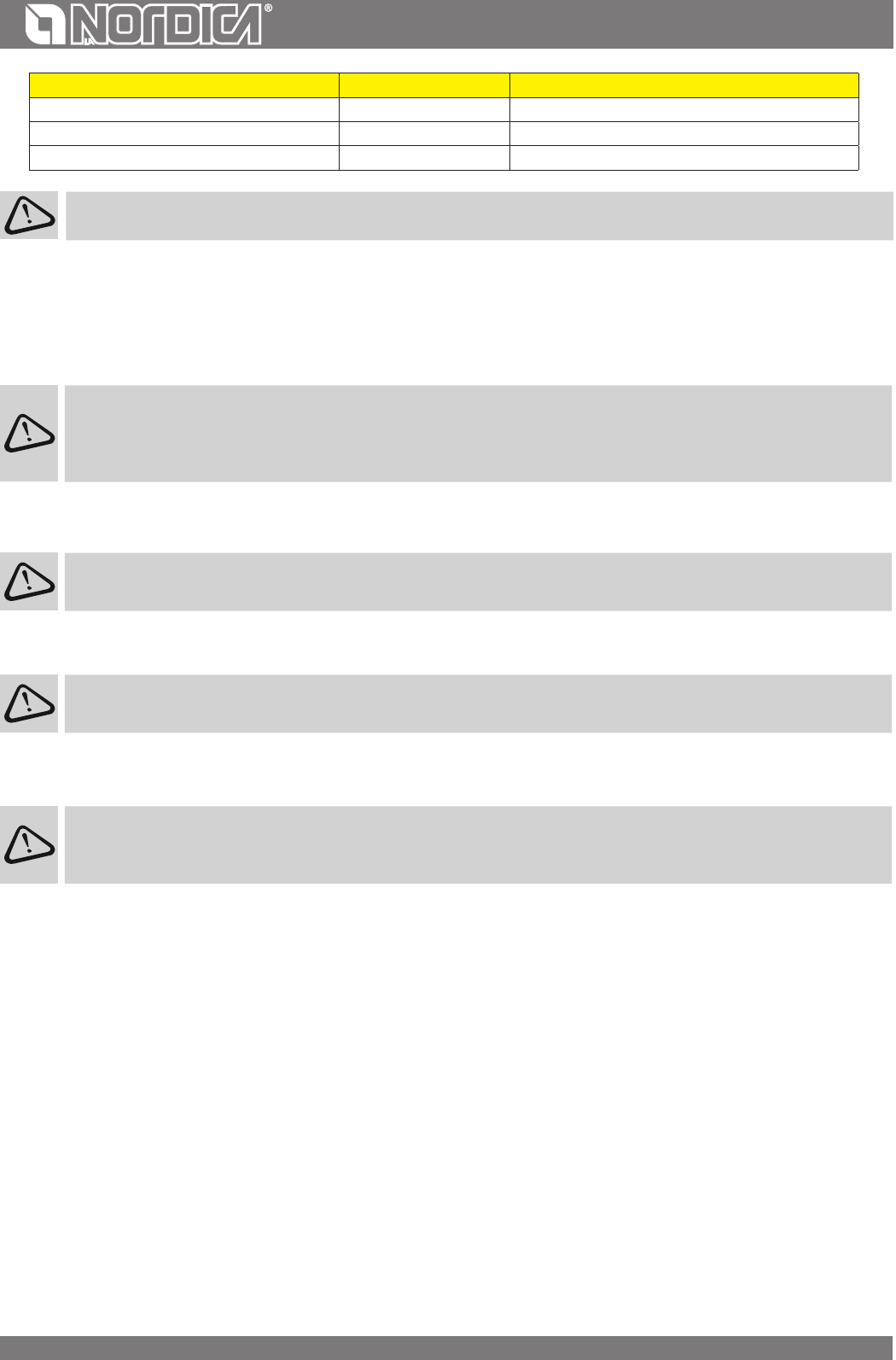
Approximate combustion valueRequired quantity in relation to
1 kg of dry wood
FuelUnitkcal/hkW
Dry wood (15% humidity)
kg36004.21,00
Wet wood (50% humidity)kg18502.21,95
Wood briquetteskg40005.00,84
Brown coal briquetteskg48005.60,75
Normal anthracitekg77008.90,47
Cokekg67807.90,53
Natural gasm
3
78009.10,46
NaphthaL85009.90,42
ElectricitykW/h8601.04,19
33
ENGLISH
GUARANTEE TERMS
1. La Nordica S.p.A. products are guaranteed, within the European community, for 24 months from the date of purchase.
Purchase has to be proved by means of a valid scal document issued by the seller (receipt, invoice or shipment document) identifying the
purchased product and its purchase and/or delivery date.
WARNING: This conventional guarantee does not replace the guarantee regulated by the European legislation on consumer rights.
The conventional guarantee is only applicable to the Italian region and to those areas, within the European Community, where the Authorised
Technical Assistance Centres are active (see the www.lanordica-extraame.com website)
It is also limited to the state of residence of the consumer, which must coincide with the premises and/or registered oce of the seller of the
La Nordica S.p.A. product
These regulations do not apply if the product is purchased within commercial, entrepreneurial, or professional circumstances. In these cases
the product guarantee will be limited to a period of 12 months from the date of purchase.
ITALIAN GUARANTEE
What must be done if there is a product malfunction:
Consult the instructions manual to make sure the malfunction cannot be solved by using the product correctly. Make sure the malfunction is
included in those covered by the guarantee; otherwise the cost of the intervention will be borne entirely by the consumer. When requesting
the intervention of the Assistance service at the Authorised Assistance Centre, always specify: - type of malfunction - model of the appliance
- complete address - phone number
EUROPEAN GUARANTEE
What must be done if there is a product malfunction:
Consult the instructions manual to make sure the malfunction cannot be solved by using the product correctly. Make sure the malfunction
is included in those covered by the guarantee; otherwise the cost of the intervention will be borne entirely by the consumer. Request the
intervention of the Assistance service or the address of the Authorised Technical Assistance Centre to the seller; always specify: type of
malfunction, model of the appliance, complete address and phone number
If the malfunction arises in the rst 6 months of the product’s life, the consumer has the right to have the product repaired with no expense.
From the seventh to the twenty-fourth month, if a malfunction arises, the consumer will bear the cost of the call, while the seller will pay
for the manpower and for any spare parts used.
2. If the malfunction is linked to external events and/or conditions such as, including but not limited to, insucient capacity of the systems;
wrong installation and/or maintenance by the personnel which hasn’t got the skills prescribed by the laws of the country of residence of
the consumer; negligence; inability to use the product and wrong maintenance by the consumer, with respect to what is reported and
recommended by the instructions manual of the product, which is part of the sales contract, this guarantee will be void.
Damage to the product that cannot be related to manufacturing defects are also not included in this guarantee. Similarly are excluded defects
related to incorrect operation of the ue, according to the legislation in force in the country at the moment of purchase. Other exclusions
include all product defects due to carelessness, accidental breakdown, tampering and/or damage during transport (scratches, dents, etc.),
interventions carried out by unauthorised personnel and further damage caused by incorrect interventions by the consumer trying to arrange
the initial malfunction.
The following consumables are excluded by the guarantee: gaskets, ceramic or tempered glasses, cast iron grilles or coatings, refractory
materials (e.g. Nordiker or others), painted, chrome-plated or golden parts, majolica ware, handles, the brazier and its related components.
For Idro products the heat exchanger is not covered by the guarantee if a suitable condensation-proof circuit is not set up to ensure a return
temperature of the device of at least 55°C. The guarantee excludes all the external components on which the consumer can directly operate
during use and/or maintenance or that can be subject to wear and/or rust and stains on steel due to aggressive detergents.
If malfunctions are signalled which are not later conrmed during check by an authorised technician, the cost of the intervention will be borne
entirely by the consumer.
3. If it is not possible to restore product conformity by repairing it, the product/component will be replaced, the guarantee expiration date and
conditions will remain the same established when the product/component to be replaced has been purchased.
4. La Nordica S.p.A. cannot be held liable for injury or damage which may - either directly or indirectly - be caused to persons, animals
and property ensuing from failure to observe all the instructions provided in the relevant instruction manual and the warnings regarding
installation, use and maintenance of the product, that can also be downloaded on the website.
5. Interventions for adjusting and/or regulating the product for the type of fuel or other reasons are excluded by the guarantee.
6. If the product is repaired in one of the Authorised Technical Assistance Centres indicated by La Nordica S.p.A. and if the product is replaced,
transport will be free of charge. If the technician can repair the product at the user’s place of residence and they refuse, transport to the
workshop and redelivery will be paid by the consumer.
34
ENGLISH
7.After the 24 months of the guarantee have elapsed any repair intervention cost will be completely borne by the consumer.
8. In the case of disputes the only competent court is that of the La Nordica S.p.A. registered oce - (Vicenza-Italy)
ADDITIONAL WARNINGS
• Only use the fuel recommended by the manufacturer. The product must not be used as an incinerator.
• Do not use the product as a ladder or supporting structure.
• Do not place laundry on the product to dry it. Any clothes-horse or similar objects must be kept at due distance from the product.
Danger of re or damage to the coating.
• The user is fully liable for any incorrect use of the product. The manufacturer bears no civil or criminal liability for incorrect use.
• Unauthorised tampering of any nature or replacement of spare parts of the product with non-original parts may endanger the
operator and the manufacturer bears no civil or criminal liability for this.
• Large parts of the surface of the product can get very hot (door, handle, glass, smoke outlet pipes, etc.). Please therefore avoid coming
into contact with these parts without wearing suitable protective clothing or using appropriate measures, such as heat protective
gloves.
• DO NOT use the product with the door open or if the glass is broken.
• The product must be electrically connected to a system equipped with an operational earthing system.
• Turn o the product in the event of a failure or malfunctioning.
• Do not wash the product with water. Water may penetrate into the unit and cause faults in the electrical insulation. This can cause
electric shocks.
• Installations not complying with the regulations in force, as well as incorrect use and failure to comply with the maintenance scheduled
by the manufacturer, will invalidate the guarantee.
35
DEUTSCH
ACHTUNG
DIE OBERFLÄCHEN KÖNNEN SEHR HEISS WERDEN!
VERWENDEN SIE IMMER SCHUTZHANDSCHUHE!
Während der Verbrennung wird Wärmeenergie freigegeben, was zu einer bedeutenden Erhitzung der Oberächen, von Türen, Grien,
Steuerungen, Glas, Abgasrohr und eventuell der Vorderseite des Geräts führt.
Vermeiden Sie den Kontakt mit diesen Elementen ohne entsprechende Schutzkleidung (Schutzhandschuhe in der Ausstattung).
Stellen Sie sicher, dass Kinder sich dieser Gefahren bewusst sind und halten Sie sie vom Feuerraum während seines Betriebs fern.
KONFORMITÄTSERKLÄRUNG DES HERSTELLERS .........................................................................................................................................38
VERBINDUNG UND LADEN DER ANLAGE............................................................................................................................................................................................................................41
VERBINDUNG ZUM SCHORNSTEINROHR ............................................................................................................................................................................................................................43
LUFT FÜR DIE VERBRENNUNG .................................................................................................................................................................................................................................................44
BELÜFTUNG DER INSTALLATIONSRÄUME ..........................................................................................................................................................................................................................44
NORMALER BETRIEB ........................................................................................................................................................................................46
BETRIEB IN DEN ÜBERGANGSPERIODEN.............................................................................................................................................................................................................................47
WARTUNG UND PFLEGE ..................................................................................................................................................................................48
REINIGUNG DES GLASES ............................................................................................................................................................................................................................................................48
REINIGUNG DES ASCHENKASTENS .......................................................................................................................................................................................................................................48
REINIGUNG DES SCHORNSTEINROHRES .............................................................................................................................................................................................................................48
WARTUNG DER TELESKOPFÜHRUNGEN ..............................................................................................................................................................................................................................49
WARTUNG DER HYDRAULIKANLAGE ....................................................................................................................................................................................................................................49
FESTSTELLUNG DER WÄRMELEISTUNG .........................................................................................................................................................49
MISES EN GARDE .............................................................................................................................................................................................. 53
DÉCLARATION DE CONFORMITÉ DU CONSTRUCTEUR ................................................................................................................................ 54
REGLES POUR LA MISE EN PLACE ...................................................................................................................................................................54
VMA SOUPAPE MÉLANGEUSE ANTICONDENSATION OBLIGATOIREMENT PEUT ÊTRE FOURNIE EN OPTION ................................................................................56
VAST SOUPAPE DÉCHARGE THERMIQUE AUTOMATIQUE DSA PEUT ÊTRE FOURNIE EN OPTION ........................................................................................................57
RACCORDEMENT ET CHARGEMENT DE L’INSTALLATION ............................................................................................................................................................................................57
SÉCURITÉ CONTRE LES INCENDIES ................................................................................................................................................................57
INTERVENTION RAPIDE ..............................................................................................................................................................................................................................................................57
PROTECTION DES POUTRES .....................................................................................................................................................................................................................................................57
TÉTÉ DE CHEMINEE ......................................................................................................................................................................................................................................................................59
CONNEXION AU TUYAU D’ÉVACUATION .............................................................................................................................................................................................................................59
AIR POUR LA COMBUSTION .....................................................................................................................................................................................................................................................59
VENTILATION ET AÉRATION DES PIÈCES POUR L’INSTALLATION ..............................................................................................................................................................................60
COMBUSTIBLES ADMIS / NON ADMIS ............................................................................................................................................................60
ALLUMAGE À BASSES ÉMISSIONS ..........................................................................................................................................................................................................................................62
FONCTIONNEMENT NORMAL ......................................................................................................................................................................... 62
FONCTIONNEMENT PENDANT LES PÉRIODES DE TRANSITION ...............................................................................................................................................................................63
UTILISATION PENDANT L’ÉTÉ ...................................................................................................................................................................................................................................................63
ENTRETIEN ET SOIN ..........................................................................................................................................................................................63
NETTOYAGE DE LA VITRE ...........................................................................................................................................................................................................................................................63
NETTOYAGE TIROIR DES CENDRES ........................................................................................................................................................................................................................................64
NETTOYAGE DU TUYAU D’ÉVACUATION DE LA FUMÉE .................................................................................................................................................................................................64
ARRÊT PENDANT L’ÉTÉ ................................................................................................................................................................................................................................................................64
ENTRETIEN DE L’INSTALLATION HYDRAULIQUE ..............................................................................................................................................................................................................65
DÉTERMINATION DE LA PUISSANCE THERMIQUE ........................................................................................................................................65
CONDITIONS DE GARANTIE ............................................................................................................................................................................66
WF25 11Figura 8 C FERMÉEFigura 8 C OUVERTEPRÉ CALIBRE
WF25 X8Figura 8 C FERMÉEFigura 8 C OUVERTEPRÉ CALIBRE
WF25 Plus5,4Figura 8 C FERMÉEFigura 8 C OUVERTEPRÉ CALIBRE
TUYAU D’EVACUATION
Conditions fondamentales pour un correct fonctionnement de l’appareil:
• la section interne doit être préférablement circulaire;
• être thermiquement isolé et imperméable et construit avec matériaux appropriés pour résister à la chaleur, aux produits de la
combustion et aux éventuelles condenses;
• être sans étranglements et avoir un parcours vertical avec déviations non supérieures à 45°;
• si déjà usé, il doit être propre;
• toutes les parties du conduit des fumées doivent pouvoir être inspectées;
• des ouvertures d’inspection doivent être prévues pour le nettoyage.
• respecter les données techniques du manuel d’instructions;
Si les tuyaux d’évacuation sont à section carrée ou rectangulaire les arêtes internes doivent être arrondies avec rayon non inférieur à 20 mm.
Pour la section rectangulaire le rapport maximum entre les côtés doit être = 1,5.
Une section trop petite provoque une diminution du tirage. On conseille une hauteur minimale de 4 m.
On interdit car ils aectent le bon fonctionnement de l’appareil: brociment, acier galvanisé, surfaces internes rugueuses et poreuses. en
Figure 3 on indique quelques exemples de solution
Les sections/longueurs du conduit de fumée indiquées dans le tableau des DONNEES TECHNIQUES sont des indications
pour une installation correcte. La Norme EN13384-1 vaut pour toute installation avec dimensions diérentes.
58
FRANCAIS
Le tirage créé par votre tuyau d’évacuation doit être susant mais pas excessif.
Une section du tuyau d’évacuation trop importante peut présenter un volume trop grand à chauer et donc provoquer des dicultés de
fonctionnement de l’appareil; pour éviter cela il faut incuber le même au long de toute son hauteur. Une section trop petite provoque une
diminution du tirage.
ATTENTION: en ce qui concerne la réalisation du branchement au conduit des fumées et les matériaux inammables il faut se
conformer à la Norme UNI10683. Le conduit de fumée doit être distancé des matérielles inammables ou combustibles à travers
une appropriée isolation or une interstice d’air.
Il est INTERDIT de faire passer intérieurement au conduit de fumée tuyaux d’ installation ou canaux pour l’adduction d’air. Il est
aussi interdit de créer des ouvertures, mobiles ou xes pour la connexion d’ autres appareils (Figure 4).
TÉTÉ DE CHEMINEE
Le tirage du conduit de fumée dépend aussi d’une tête de cheminée appropriée.
Il est donc indispensable que, si construite artisanalement, la section de sortie soit plus de deux fois la section interne du conduit de fumée
(Figure 5).
Puisqu’on doit toujours récupérer la ligne de faîte du toit, la tête de cheminée devra assurer le déchargement même en présence de vent
(Figure 6).
La tête de cheminée doit répondre aux suivantes conditions:
• avoir section interne équivalent à celle de la cheminée.
• avoir section utile de sortie double par rapport à celle interne du conduit de fumée.
• être construite de façon à empêcher la pénétration dans le conduit de fumée de pluie, neige ou de tout corps étrange.
• être facilement inspectionnable, pour éventuelles opérations d’entretien et nettoyage.
CONNEXION AU TUYAU D’ÉVACUATION
La connexion à la cheminée doit être réalisée avec tuyaux rigides en acier conforme à toutes les Normes et aux Réglementations actuelles
prévues par la Loi.
Il est INTERDIT d’utiliser des tubes métalliques exibles ou en brociment puisqu’ils ne garantissent pas la sécurité du
raccord pouvant être objets de déchirures ou ruptures, ce qui provoquerait des échappements de fumée.
Le conduit de décharge fumée doit être xé hermétiquement à la cheminée et ne peut avoir qu’une inclinaison maximum de 45°, ceci pour
éviter des dépôts excessifs de condensation produite au cours des phases initiales d’allumage et/ou la xation excessive de suie ainsi que le
ralentissement des fumées en sortie. Un raccordement non hermétique peut provoquer un mauvais fonctionnement de l’appareil.
Le diamètre interne du tuyau de raccordement doit correspondre au diamètre externe du tronc de décharge fumée de l’appareil. Les tuyaux
selon DIN 1298 remplissent cette condition.
La dépression à la cheminée (TIRAGE) doit être d’au moins 12 Pascal (=1.2 mm de colonne d’eau).Le mesure doit être fait toujours avec
appareil chaud (rendement calorique nominal). Quand la dépression dépasse 17 Pa (=1.7 mm de colonne d’eau) il faut réduire la même avec
l’installation d’un régulateur de tirage supplémentaire (vanne papillon) sur le tuyau d’échappement ou dans la cheminée selon les normatives
en vigueur.
IMPORTANT: Avec l’emploi de tuyaux métalliques il est indispensable qu’ils soient isolés avec matériaux appropriés
(revêtements en bre isolante résistants jusqu’à 600°C) dans le but d’éviter détériorations des maçonneries ou de la contre-
hotte.
AIR POUR LA COMBUSTION
Il est indispensable que l’espace compris entre la partie supérieure, les côtés de l’appareil et le déecteur de matériaux incombustible de la
hotte (qui obture la base du tuyau d’évacuation), soit constamment ventilé.
Il faut permettre pour cela une entrée d’air d’en bas (entrée d’air frais) et une sortie haute (sortie d’air chaud).
Les espaces prévus pour la circulation de l’air indiqués dans la (Figure 7 - Figure 14) sont les conditions minimales:
Sommet: ouverture minimale 800 cm
2
Base: ouverture minimale 600 cm
2
On obtient donc:
• une plus grande sécurité
• une augmentation de la chaleur créée par la circulation d’air autour de l’appareil
• améliorer le fonctionnement de l’appareil
La grille évacuation chaleur (Figure 7 pos. 6 ) se trouve sur la parte supérieure du manteau à 20 cm du plafond. Cette grille doit
être toujours installée car sa fonction est de permettre la sortie de la chaleur accumulée dans l’ambiance (surpression).
ATTENTION : Nous conseillons de réaliser la contre-chape en carton-plâtre ignifugé avec châssis métallique autoportant, de façon
à ce que son poids ne repose pas sur le revêtement esthétique (marbre). On conseille de prévoir une porte d’inspection sur la
contre-chape ou là où il est plus convenable pour y accéder facilement et pour une bonne visibilité des dispositifs de sécurité
(manomètres, vannes, calculateur, ..).
59
FRANCAIS
VENTILATION ET AÉRATION DES PIÈCES POUR L’INSTALLATION
Vu que les appareils prennent leur air de combustion de la pièce d’installation, il est OBLIGATOIRE qu’il existe une quantité susante d’air
dans ce lieu. En cas de fenêtre et portes étanches (ex. Maisons construites avec le critère de l’épargne énergétique) il est possible que l’entrée
d’air frais ne soit plus garantie et ceci compromet le tirage de l’appareil, votre bien-être et votre sécurité.
IMPORTANT:Pour un meilleur bien-être et une meilleure oxygénation de l’ambiante, l’air de combustion peut être prise directement de
l’extérieur avec un raccord de connexion à un tuyau exible. Le tuyau de connexion (qui n’est PAS fourni) doit être poli, avec un diam. min. de
Figure 13 et longueur max. 4m et avec pas plus de trois courbes. Dans le cas où il soit branché directement avec l’extérieur il faut prévoir un
brisevent.
Pour un bon fonctionnement de l’appareil il est OBLIGATOIRE que dans le lieu d’installation on introduit de l’air susant pour la combustion
et la ré-oxygénation de l’environnement même. Cela signie que, à travers des ouvertures appropriées en communication avec l’extérieur, l’air
pour la combustion doit pouvoir circuler même avec les portes et les fenêtres fermées.
Les prises d’air doivent répondre aux exigences suivantes:
• être protégées par des grilles, grillages métalliques, etc., sans en réduire la section utile nette;
• être réalisées de façon à rendre possibles les opérations de maintenance;
• être placées de façon à ne pas pouvoir être bouchées;
• Si dans la pièce où l’appareil est installé il y a des hottes d’aspiration, celles-ci NE DOIVENT PAS fonctionner au même temps que l’appareil.
Il pourrait se vérier une sortie de fumée dans la pièce, même avec porte fermée de l’appareil.
L’aux de l’air propre et non contaminé peut être obtenu aussi d’une pièce adjacente à celle de l’installation (aération et ventilation indirecte),
à condition que le ux puisse se faire librement à travers des ouvertures permanentes en communication avec l’extérieur.
La pièce adjacente ne peut pas être utilisée comme garage, stock de matériau combustible ou autres activités comportant un danger
d’incendie, salle de bains, chambre à coucher ou pièce commune de l’immeuble.
La ventilation est susante quand la pièce est équipée de prises d’air selon le tableau:
les catégories d'appareilsla norme de référence
le pourcentage de la section
nette d'ouverture par rapport à la section de
sortie des fumées de l'appareil
la valeur minimale nette
d'ouverture du conduit de
ventilation
CheminéesUNI EN 1322950%200 cm²
PoêlesUNI EN 1324050%100 cm²
CuisinièreUNI EN 1281550%100 cm²
L’installation dans les pièces avec danger d’incendie est interdite. Il est également interdit d’eectuer l’installation à l’intérieur de
pièces à usage d’habitation dans lesquelles la dépression mesurée entre milieu extérieur et milieu intérieur serait supérieure à 4 Pa
- référence pour l’Italie conformément à la norme UNI10683.
Il faut se conformer à toutes les lois et règlementations nationales, régionales, provinciales et communales existant dans le pays où l’appareil
a été installé.
COMBUSTIBLES ADMIS / NON ADMIS
Les combustibles admis sont souches de bois. On doit utiliser exclusivement souches de bois sec (contenu d’eau max. 20%). On devrait charger
au maximum 2 ou 3 souches de bois. Les pièces de bois devraient avoir une longueur d’environ 20-30 cm et une circonférence de maximum
30-35 cm. Les petits troncs de bois pressés non résines doivent être usés avec attention pour éviter surchauages dangereux pour
l’appareil, car ils ont un pouvoir calorique très haut.
Le bois utilisé comme combustible doit avoir un contenu d’humidité inférieur au 20% et doit être déposé dans un lieu sec. Le bois humide
rende l’allumage plus dicile, car il faut une plus grande quantité d’énergie pour faire évaporer l’eau présente. Le contenu humide a en outre
le désavantage que, avec la réduction de la température, l’eau se condense d’abord dans le foyer et donc dans le cheminée, causant ainsi un
remarquable dépôt de suie avec suivant possible risque d’incendie de la même.
Le bois frais contient environ 60% d’humidité (H
2
O), donc il n’est pas convenable pour être brûlé. Il faut placer ce bois dans un lieu sec et ventilé
(par exemple sous un abri) pour au moins deux ans avant son emploi.
Parmi les autres, on ne peut pas brûler: charbon, découpes, déchets d’écorce et panneaux, bois humide ou traité avec vernis,
matériaux en plastique; dans ce cas échoit la garantie sur l’appareil. Papier et carton doivent être utilisés seulement pour l’allumage.
La combustion de déchets est INTERDITE et endommagerait en outre l’appareil et le tuyau d’évacuation de la fumée, nuisant également à
la santé et pouvant donner lieu à des réclamations de la part des voisins à cause des mauvaises odeurs.
Le bois n’est pas un combustible de longue durée et par conséquent un chauage continu du poêle pendant la nuit n’est pas possible.
Typekg/mckWh/kg Humidité 20%
Hêtre7504,0
Chêne9004,2
Orme6404,1
Peuplier4704,1
Mélèze*6604,4
60
FRANCAIS
Typekg/mckWh/kg Humidité 20%
Sapin rouge*4504,5
Pin Silvestre*5504,4
* BOIS RÉSINEUX PEU ADAPTES POUR UN POÊLÉ
IMPORTANT: En utilisant de façon continue et prolongée du bois aromatisé (eucalyptol, myrte, etc.), on cause rapidement
des dégâts (clivage) au niveau des éléments en fonte du produit.
Les données techniques déclarées ont été obtenues en utilisant l’essence d’hêtre en classe “A1” selon la norme UNI EN ISO 17225-5 et humidité au
dessous de 20%. Utiliser d’autre essence pourrait exiger des régulations spéciques et procurer des rendements du produit diérents.
ALLUMAGE
ATTENTION: En aucun cas il ne faut allumer le feu avant que l’installation ait été totalement remplie d’eau; cela risquerait
d’endommager gravement toute la structure. EN CAS DE MANQUE TOTAL OU PARTIEL D’EAU, NE PAS ALLUMER LE FEU
DANS
L’APPAREIL (MÉMÉ PAS COMME TEST) PARCE QUE CELLE-CI POURRAIT SOUFFRIR UN DOMMAGE IRRÉPARABLE ET DANS CE
CAS, LA GARANTIE SUR L’APPAREIL NE SERAIT PLUS VALABLE.
Avant d’installer le revêtement esthétique et d’allumer la cheminée, il faut remplir, par chute naturelle d’eau, l’installation et la cheminée au
moyen du vase d’expansion ouvert (voir chap. RACCORDEMENT ET CHARGEMENT DE L’INSTALLATION). Après s’être assuré qu’au moins un
thermosiphon est toujours ouvert, ouvrir la porte en la levant vers le haut à l’aide de la poignée prévue et charger une petite quantité de
bois. Pour allumer le feu, nous conseillons d’utiliser du petit bois et du papier ou bien d’autres moyens vendus dans le commerce.
Il est INTERDIT d’utiliser toute substance liquide comme par ex. alcool, essence, pétrole et similaires. Ne jamais allumer
l’appareil en présence de gaz carburant dans la pièce.
Le réglage pour l’air (primaire et secondaire) doit être ouvert un petit peu au même temps. Quand le bois commence à brûler, on peut
charger plus de combustible et contrôler la combustion au moyen de l’air de combustion selon les indications du chap. DESCRIPTION
TECHNIQUES.
Pendant cette phase, ne jamais laisser le foyer sans supervision. Jamais surcharger l’appareil (chap. DESCRIPTION TECHNIQUE
- Consommation horaire). Trop de combustible et trop d’air pour la combustion peuvent causer surchauage et donc
endommager le même.
Il est inévitable qu’au premier allumage, se produise une odeur désagréable (due au séchage des collants d’étanchéité ou des vernis de
protection), qui disparaît après une brève utilisation. Il faut cependant assurer une bonne ventilation du milieu ambiant.
ATTENTION: au cours des premiers allumages, il pourra se produire une condensation importante des fumées et un petit
écoulement d’eau de la cheminée; il s’agit d’un phénomène passager destiné à disparaître rapidement, si par contre, ce
phénomène devait continuer, il faudra faire contrôler le tirage du tuyau d’évacuation de la fumée.
Pour eectuer un premier allumage correct des produits traités avec des vernis pour hautes températures, il faut savoir ce qui suit:
• les matériaux de construction des produits en question ne sont pas homogènes, en eet coexistent des pièces en fonte, en acier, en
matériel réfractaire et en faïence ;
• la température à laquelle est soumis le corps du produit n’est pas homogène: selon les zones, les températures peuvent varier de 300ºC
à 500ºC ;
• le long de sa vie, le produit est soumis à des cycles alternés d’allumage et d’arrêt au cours de la même journée et à des cycles d’utilisation
intense ou de repos absolu selon les saisons ;
• l’appareil neuf, avant de pouvoir être considéré comme rodé, devra être soumis à diérents cycles de mise en service pour permettre
à tous les matériaux et au vernis de compléter les diverses sollicitations élastiques;
• en particulier, initialement, il est probable qu’on notera l’émission d’odeurs typiques de métaux soumis à une grande sollicitation
thermique et de vernis encore frais. Bien que pendant la phase de fabrication, ce vernis soit cuit à 250ºC pendant quelques heures, il
devra dépasser plusieurs fois et pendant un certain temps la température de 350ºC avant de s’incorporer parfaitement aux supercies
métalliques.
Il est donc important de suivre ces quelques instructions au moment de l’allumage:
1. Assurez-vous que soit garanti un renouvellement important de l’air dans le lieu où est installé l’appareil.
2. Pendant les premiers allumages, ne pas charger excessivement la chambre de combustion (environ la moitié de la quantité indiquée
dans le manuel d’instructions) et maintenir le produit allumé pendant au moins 6-10 heures de suite, avec les régulateurs moins
ouverts que ce qui est indiqué dans le manuel d’instruction.
3. Répéter cette opération au moins 4-5 fois ou plus, selon votre disponibilité.
4. Par la suite augmenter progressivement la charge (en respectant cependant toujours les indications du manuel d’instruction au sujet
de la charge maximum) et si possible, observer de longues périodes d’allumage en évitant, au moins au cours de la phase initiale, des
cycles d’allumage-arrêt de courte durée.
5. Au cours des premiers allumages, aucun objet ne devrait être appuyé sur l’appareil et en particulier sur les supercies laquées.
Il ne faut pas toucher les supercies laquées pendant le chauage.
61
FRANCAIS
6. Une fois le «rodage» terminé, l’appareil pourra être utilisé comme le moteur d’une auto, en évitant de brusques échauements causés
par des chargements excessifs.
Seulement après quelques jours de fonctionnement, quand on est sure que l’appareil fonctionne correctement, on peut
procéder avec la construction du revêtement esthétique.
AVERTISSEMENT: Pour la construction du sol, il faut considérer éventuelles et successives entretiens des parties électriques
installées (par ex. ventilateurs, sondes de température, etc.) et des dispositifs branchés au thermo-produit, là où il existe une
installation hydraulique.
ALLUMAGE À BASSES ÉMISSIONS
La combustion sans fumée est une méthode d’allumage qui permet de réduire notablement les émissions de substances nocives. Le bois
brûle progressivement du haut vers le bas, ainsi la combustion et plus lente et mieux contrôlée. Les gaz brûlés, en passant à travers les
ammes, brûlent presque entièrement.
Mettre les bûches dans le foyer à une certaine distance l’une de l’autre, comme indiqué dans la Figure 15. Disposer les plus grosses en bas et
les plus minces en haut, ou à la verticale en cas de foyer étroit et haut. Placer l’allume-feu sur le montage, disposer des bûches sur l’allume-feu
perpendiculairement au tas de bois.
Mode d’allumage. Ce mode d’allumage remplace le papier ou le carton. Préparer quatre bûches ayant une section transversale de 3cm x 3cm
et une longueur de 20 cm Figure 15. Mettre les quatre bûches croisées au-dessus du tas de bois, transversalement à celui-ci, avec au milieu
l’allume-feu qui peut être par exemple de la bre de bois enduite de cire. Une allumette sut pour allumer le feu. Il est également possible
d’utiliser des morceaux de bois plus petits: dans ce cas il en faudra un plus grand nombre. Ouvrir la vanne d’évacuation des fumées et le
clapet pour l’air comburant.
Après avoir allumé le feu laisser le clapet qui régule l’air pour la combustion dans la position indiquée dans la Figure.
IMPORTANT:
• ne pas recharger
l’appareil;
• ne pas étouer le feu en fermant les prises d’air;
• un ramonage régulier réduit les émissions de poussières nes.
Ces indications sont soutenues par ENERGIA Legno SUISSEwww.energia-legno.ch
FONCTIONNEMENT NORMAL
Après avoir positionné le clapet de la soupape fumées correctement (possiblement fermé), introduire le charge de bois horaire indiqué évitant
des surcharges qui provoquent des eorts anormaux et déformations.
Vous devez utiliser l’appareil toujours avec la porte fermée, pour éviter des problèmes dû au surchauage (forge eet).La
non observance de cette règle fait échoir la garantie.
MPORTANT: Pour des raisons de sécurité, la porte du foyer ne peut être ouverte que pendant le chargement du
combustible. Le foyer doit rester fermé pendant le fonctionnement et les périodes pendant lesquelles l’appareil
n’est pas utilisé
Avec les clapets placés sur la façade de l’appareil on règle son émission de chaleur. Ils doivent être ouverts selon le besoin calorique. La
meilleure combustion (avec émissions minimales) est rejointe lorsque quand, en chargeant le bois, la plu part de l’air pour la combustion
passe à travers le clapet d’air secondaire.
Jamais surcharger l’appareil. Trop combustible et trop sari pour la combustion peuvent causer une surchaue et par conséquence
endommager l’appareil. Les dommages causés par surchaue ne sont pas couverts par garantie. Il faut donc toujours utiliser l’appareil
avec la porte fermée (abaissée) pour éviter l’eet forge.
Le réglage des clapets nécessaire pour obtenir le rendement calorique nominal est le suivant:: voir chap. DESCRIPTION TECHNIQUE. Le
appareil est un appareil à alimentation intermittente.
Dans le cas où la température de l’eau dépasse la température d’intervention des sécurités, suspendre immédiatement le
chargement du bois, vérier que la température de l’eau et de la amme diminue en éliminant les causes de la surchaue
(fermer éventuellement le régulateur d’air). Si l’eau sanitaire est raccordée à l’appareil, il est possible d’ouvrir le robinet
d’eau chaude pour accélérer le refroidissement de l’appareil.
Outre au réglage de l’air pour la combustion, l’intensité de la combustion et donc le rendement calorique de votre appareil est aecté par
la cheminée. Un bon tirage de la cheminée demande un réglage plus réduit de l’air pour la combustion, tandis qu’un tirage réduit nécessite
davantage d’un exact réglage de l’air pour la combustion.
Pour vérier la bonne combustion, contrôler si la fumée qui sort de la cheminée est transparente. De la fumée blanche signie que l’appareil
n’est pas réglé correctement ou que le bois est trop mouillé; par contre, de la fumée grise ou noire indique que la combustion n’est pas
complète (une plus grande quantité d’air secondaire est nécessaire).
ATTENTION : Lorsque l’on rajoute le combustible sur les braises en l’absence de amme, un développement important de fumées
pourrait être constaté. Dans ce cas, un mélange explosif de gaz et d’air pourrait se former et, dans les cas extrêmes, une explosion.
Pour des motifs de sécurité, il est conseillé d’eectuer une nouvelle procédure d’allumage en utilisant des petites baguettes en bois.
ABSENCE D’ENERGIE ELECTRIQUE
En cas d’une interruption imprévue de l’alimentation électrique pendant le fonctionnement normal de l’installation, il faudra prendre ces
62
FRANCAIS
simples précautions pour éviter que la cheminée n’entre en ébullition suite à l’absence du fonctionnement de la pompe.
• Fermer complètement les régulateurs de l’air primaire et secondaire de façon à suoquer le plus possible le feu.
• Fermer le régulateur fumées, si présent, pour limiter encore plus l’arrivée de l’air comburant à travers d’éventuelles fentes.
FONCTIONNEMENT PENDANT LES PÉRIODES DE TRANSITION
Pendant la période de transition, c’est-à-dire quand les températures externes sont plus élevées, en cas d’augmentation imprévue de la
température, il peut se produire certaines dicultés avec le tuyau d’évacuation de la fumée qui font que les gaz de combustion ne sont pas
complètement aspirés. Les gaz de décharge ne sortent plus complètement (forte odeur de gaz).
Dans de tels cas, secouez plus fréquemment la grille et augmenter l’air pour la combustion. Ensuite chargez une quantité réduite de
combustible en faisant en sorte que celui-ci brûle plus rapidement (avec plus de ammes) et le tirage du tuyau d’évacuation de la fumée se
stabilise. Contrôlez également que toutes les ouvertures pour le nettoyage et les raccordements à la cheminée soient hermétiques. En cas
d’incertitudes, renoncer à utiliser l’appareil.
ATTENTION: En aucun cas il ne faut allumer le feu avant que l’installation ait été totalement remplie d’eau; cela risquerait
d’endommager gravement toute la structure. L’installation doit être toujours remplie d’eau aussi pendant les périodes de non
utilisation du produit thermique. Pendant l’hiver il faut y ajouter des substances antigel dans le cas où l’appareil ne soit pas utilisé.
UTILISATION PENDANT L’ÉTÉ
Il faut toujours avoir de l’eau dans l’installation, l’absence d’eau risquerait d’endommager gravement toute la structure.
ATTENTION: En aucun cas il ne faut allumer le feu avant que l’installation ait été totalement remplie d’eau; cela risquerait
d’endommager gravement toute la structure.
Pour éviter l’ébullition de l’eau dans la chaudière, la pompe de circulation de l’installation devra TOUJOURS être en fonction pour
pouvoir évacuer sur les radiateurs, ou bien sur l’hydroaccumulateur (puffer), ou sur des autres structures absorbantes, la chaleur
restant à l’eau provenant de la chaudière.
Si la pompe ne devait pas fonctionner ou, pour quelconque raison la température de l’eau devait dépasser 95° C,
la valve DSA intervient en déchargent la chaleur avec de l’eau à perdre (froide). On recommande de contrôler la
température de l’eau du produit thermique pendant l’utilisation en été, pour éviter des interventions répétées de
la valve DSA qui pourraient affecter le bon fonctionnement.
ENTRETIEN ET SOIN
Contrôler, en le nettoyant, au moins une fois par an, la prise d’air externe.
La cheminée doit être régulièrement ramonée par le ramoneur.
Faites contrôler par votre ramoneur de zone l’installation de la cheminée, le raccordement et l’aération.
IMPORTANT: ENTRETIEN ET SOIN QUI NE PEUT AVOIR LIEU QU’AVEC L’APPAREIL FROID.
Utiliser exclusivement des pièces de rechange expressément autorisées et oertes par La NORDICA S.p.A. . En cas de besoin, nous
vous prions de vous adresser à votre revendeur spécialisé.
L’APPAREIL NE PEUT PAS ÊTRE MODIFIE!
NETTOYAGE DE LA VITRE
Après avoir vérié que la porte est complètement baissée, débloquer le verrou et ouvrir la porte (Figure 11pos.A), nettoyer la vitre et
refermer la porte avant de la soulever de nouveau.
Grâce à une entrée spécique de l’air secondaire, la formation de dépôts de saleté sur la vitre de la porte est ecacement ralentie. Cependant
il est impossible de l’éviter complètement avec l’utilisation des combustibles solides (en particulier le bois humide) mais ceci ne doit pas être
considéré comme un défaut de l’appareil.
IMPORTANT: Il ne faut nettoyer la vitre panoramique que quand l’appareil est froid pour en éviter l’explosion. Le nettoyage
peut être eectué avec des produits spéciques ou bien en frottant la vitre avec une boule de papier journal (quotidien) humidié
et passé dans la cendre.
Ne pas utiliser cependant de chions, produits abrasifs ou chimiquement agressifs.
63
FRANCAIS
La procédure correcte d’allumage, l’utilisation de la quantité et du type de combustibles adéquats, la position correcte du régulateur de
l’air secondaire, le tirage susant de la cheminée et la présence d’air comburant sont les conditions indispensables pour le fonctionnement
optimal de l’appareil et garantissant le nettoyage de la vitre.
RUPTURE DES VITRES: Les vitres sont en vitrocéramique résistante à des poussées thermiques allant jusqu’à 750° C et ne
sont donc pas sujettes à des chocs thermiques. Elles ne peuvent se rompre que par chocs mécaniques (coups ou fermeture
violente de la porte, etc.) Par conséquent, le remplacement de la vitre n’est pas sous garantie.
NETTOYAGE TIROIR DES CENDRES
Tous les appareils ont une grille foyer et un tiroir cendre pour la récolte des cendres.
Nous vous conseillons de vider périodiquement le tiroir cendre et d’éviter son remplissage total, pour ne pas surchauer la grille. En outre,
nous vous conseillons de laisser toujours 3-4 cm de cendre dans le foyer.
ATTENTION: Les cendres enlevées du foyer doivent être placées dans un récipient de matériau ignifuge équipé d’un
couvercle étanché. Le récipient doit être placé sur un sol ignifuge, loin de matériaux inammables jusqu’à l’extinction et
refroidissement complet.
NETTOYAGE DU TUYAU D’ÉVACUATION DE LA FUMÉE
La procédure correcte d’allumage, l’utilisation de quantités et types de combustibles appropriés, le juste positionnement du registre de l’air
Secondaire, le tirage susant de la cheminée et la présence d’air comburant sont indispensables pour le fonctionnement optimal de l’appareil
et garantissant le nettoyage de la vitre.
Nous recommandons d’eectuer un nettoyage complet de l’appareil au moins une fois par an ou chaque fois que nécessaire (problèmes
de mauvais fonctionnement avec faible rendement). Un dépôt excessif de suie peut provoquer des problèmes de décharge des fumées et
l’incendie du tuyau d’évacuation lui-même.
Cette opération, qui ne peut avoir lieu qu’avec l’appareil froid, devrait être eectuée par un ramoneur qui en même temps,
peut faire une inspection du tuyau d’évacuation de la fumée (vérier la présence d’éventuels dépôts).
Pendant le nettoyage, il faut retirer de l’appareil le tiroir cendrier, la grille et le déecteur fumées pour favoriser la chute de la suie.
Les déecteurs sont facilement amovibles depuis leurs sièges car elles ne sont pas xés avec aucune vis. Une fois le nettoyage réalisé, les
mêmes doivent être repositionnés dans leurs sièges (Figure 9 ).
ATTENTION: L’absence de déecteur provoque une forte dépression, une combustion trop rapide et une consommation
excessive de bois ayant pour conséquence une surchaue de l’appareil.
Nous recommandons d’eectuer un nettoyage complet des pièces A et B (Figure 10) au moins une fois par an ou quand il est nécessaire
(problèmes de mauvais fonctionnement avec faible rendement). Les pièces A et B sont facilement amovibles depuis leurs sièges car elles ne
sont pas xées avec des vis. Dès que le nettoyage est terminé, les mêmes doivent être repositionnées dans leurs sièges.
ARRÊT PENDANT L’ÉTÉ
Après avoir réalisé le nettoyage du foyer, de la cheminée et du conduit de la fumée, en réalisant l’élimination totale de la cendre et d’autres
éventuels résidus, il faut fermer toutes les portes du foyer et les relatifs clapets. Si l’appareil est retiré de la cheminée, il faut fermer son orice
de sortie. On conseille de réaliser l’opération de nettoyage du conduit de fumée au moins une fois par an. Il faut vérier entre temps l’eectif
état des garnitures lesquelles, si elles ne sont pas parfaitement intègres, ne garantissent pas le bon fonctionnement de l’appareil! Dans ce cas
il est nécessaire le remplacement des mêmes.
En cas d’humidité de la salle ou se trouve l’appareil, il faut préparer des sels absorbants à l’intérieur du foyer. Protéger les parties en
fonte, si l’on veut maintenir inaltéré dans le temps l’aspect esthétique, avec de la vaseline neutre.
Vérier le niveau de l’eau du vase d’expansion et faire sortir l’air éventuel de l’installation en purgeant les radiateurs, vérier en outre le
fonctionnement des accessoires hydrauliques et électriques (centrale, circulateur).
ATTENTION: En aucun cas il faut allumer le feu avant que l’installation ait été totalement remplie d’eau; cela risquerait d’endommager
gravement toute la structure. L’installation doit être toujours remplie d’eau aussi pendant les périodes de non utilisation du produit
thermique.
ENTRETIEN GUIDES EXTENSIBLES
Les portes pour fonctionner en manière silencieuse, able et robuste sont xée à des guides extensibles à billes. En utilisant en continuation
l’appareil, dans le temps, le lubriant des guides mêmes tend progressivement à s’achever en les rendant donc moins glissantes et avec
plus de bruit. Pour cette raison en dotation avec chaque appareil on fournit de gras pour haute température de manière à rendre possible la
lubrication, de la part de l’usager, des guides si cela est nécessaire (excessif bruit ou réduction de glissement).
Après avoir totalement soulevé la porte de la cheminée, usant une syringe, appliquer internement sur le rail dans le point visible le plus haut
possible, deux boules de gras (correspondantes à 0.5 ml de l’échelle graduée de la syringe).
Faire attention à ne pas excéder la quantité conseillée.Répéter la même opération sur l’autre rail et soulever plusieurs fois la porte
de façon que le gras se distribue sur toutes les billes.
ATTENTION: utiliser exclusivement le gras fournit par La NORDICA.
64
FRANCAIS
ENTRETIEN DE L’INSTALLATION HYDRAULIQUE
Un dépôt excessif d’incrustations sur les parois internes du foyer réduit énormément l’ecacité de l’échangeur thermique. Il faut
donc enlever les incrustations, quand il est nécessaire, en utilisant une spatule en acier. Ne jamais utiliser substances corrosives,
qui peuvent endommager le bouilleur ainsi que le produit thermique.
Avec l’installation éteinte et une fois par an, eectuer les vérications suivantes:
• Contrôler le fonctionnement et l’ecacité des vannes de décharge thermique et de sécurité. Dans le cas où celles-ci seraient
défectueuses, contacter l’installateur autorisé. IL EST ABSOLUMENT INTERDIT DE RETIRER OU DE MANIPULER CES SECURITES.
• Vérier l’isolation thermique du tuyau de remplissage et du tuyau de sécurité.
• S’assurer que l’installation soit chargée et sous pression, contrôler le niveau de l’eau à l’intérieur du vase d’expansion, et en vérier le
fonctionnement tout en s’assurant également de l’ecacité du tuyau de sécurité.
DÉTERMINATION DE LA PUISSANCE THERMIQUE
Il n’existe pas de règle absolue qui permette de calculer la puissance correcte nécessaire. Cette puissance dépend de l’espace à
chauffer mais aussi en grande mesure de l’isolation. En moyenne, la puissance calorique nécessaire pour une pièce adéquatement
isolée sera de 30 kcal/h par m
3
(pour une température extérieure de 0 °C).
Etant donné que 1 kW correspond à 860 kcal/h, nous pouvons adopter une valeur de 35 W/m
3
.
Supposons que vous souhaitez chauffer une pièce de 150 m
3
(10 x 6 x 2,5 m) d’un appartement isolé, vous aurez besoin de 150 m
3
x 35 W/m
3
= 5250 W ou 5,25 kW. Par conséquent, comme chauffage principal, un appareil de 8 kW sera sufsant.
Valeur indicative de combustion
Quantité demandée par rapport à
1 kg de bois sec
CarburantUnitàkcal/hkW
Bois sec (15% d’humidité)kg36004.21,00
Bois mouillé (50% d’humidité)kg18502.21,95
Briquettes de boiskg40005.00,84
Briquettes de lignitekg48005.60,75
Anthracite normalkg77008.90,47
Cokekg67807.90,53
Gaz naturelm
3
78009.10,46
MazoutL85009.90,42
ElectricitékW/h8601.04,19
65
FRANCAIS
CONDITIONS DE GARANTIE
1. Les produits La Nordica S.p.A. sont garantis, conformément aux directives de la communauté européenne, pour une période de 24 mois à
compter de la date d'achat.
Un document scal valide qui prouve l'achat, délivré par le vendeur (ticket de caisse, facture ou bon de transport), identiant le produit acheté
et la date d'achat et/ou de livraison de ce dernier est ncessaire.
ATTENTION: la présente garantie conventionnelle ne remplace pas la garantie prévue par les normes européennes pour la protection des
Consommateurs.
La garantie conventionnelle est limitée au territoire italien et aux territoires compris dans la Communauté européenne couverts par le Service
des Centres d'Assistance Technique Agréés (vérier sur le site www.lanordica-extraame.com)
Elle est également limitée au pays de résidence et/ou du domicile du consommateur qui doit être le même que celui du siège légal et/ou
commercial du vendeur du produit La Nordica S.p.A.
Les présentes normes ne s'appliquent pas aux produits achetés dans le cadre d'activités commerciales, d'entreprise ou professionnelles. Dans
ces cas, la garantie du produit sera limitée à une période de 12 mois à compter de la date d'achat.
GARANTIE ITALIE
Que faire en cas d'anomalie dans le fonctionnement du produit :
Consulter le manuel d'utilisation pour s'assurer que l'anomalie ne peut pas être résolue avec une application correcte des fonctionnalités du
produit. S'assurer que le défaut rentre dans le type d'anomalies couvertes par la garantie ; si ce n'est pas le cas, le coût de l'intervention sera
entièrement à la charge du consommateur. Lors de la demande d'intervention du Service d'Assistance au Centre d'Assistance Agréé, toujours
indiquer la nature du défaut, le modèle de l'appareil, une adresse complète et un numéro de téléphone.
GARANTIE EUROPE
Que faire en cas d'anomalie dans le fonctionnement du produit :
Consulter le manuel d'utilisation pour s'assurer que l'anomalie ne peut pas être résolue avec une application correcte des fonctionnalités du
produit. S'assurer que le défaut rentre dans le type d'anomalies couvertes par la garantie ; si ce n'est pas le cas, le coût de l'intervention sera
entièrement à la charge du consommateur. Demander l'intervention du Service d'Assistance ou l'adresse du Centre d'Assistance Technique
Agréé au vendeur en indiquant toujours la nature du défaut, le modèle de l'appareil, une adresse complète et un numéro de téléphone.
Pour les défauts de conformité apparus dans les 6 premiers mois de vie du produit, la réparation du défaut est couverte par la garantie
sans frais pour le consommateur.
En cas de vice de conformité relevé entre le septième et le vingt-quatrième mois, le coût de l'appel sera à la charge du consommateur
tandis que les frais de la main-d'œuvre et des éventuelles pièces de rechange fonctionnelles utilisées seront à la charge du vendeur.
2. La garantie est exclue si le défaut détecté est dû à des conditions et/ou évènements externes tels que, à titre d'exemple non exhaustif, une
capacité insusante des systèmes ; une installation erronée et/ou un entretien eectué par un personnel non qualié selon la législation
en vigueur dans le pays de résidence du consommateur ; une négligence ; une incapacité d'utilisation et un mauvais entretien par le
consommateur, ne correspondant pas à ce qui est indiqué dans le manuel d'utilisation du produit, lequel fait partie intégrante du contrat de
vente.
La présente garantie ne couvre pas non plus les dommages subis par le produit en l'absence de causes avérées imputables à des vices de
fabrication. De la même manière sont exclus de la présente garantie tout vice dû au dysfonctionnement du conduit de cheminée, aux termes
de la législation en vigueur dans le pays au moment de l'achat, ainsi que tous les défauts du produit dus à une incurie, rupture accidentelle,
altération et/ou dommage dans le transport (rayures, bossellements, etc.), interventions eectuées par un personnel non autorisé et autres
dommages causés par des interventions erronées du consommateur en essayant de remédier à la panne initiale.
La garantie ne couvre pas les matériaux de consommation suivants : les joints, les verres céramiques ou trempés, les revêtements et grilles
en fonte, les matériaux réfractaires (ex. Nordiker ou autre), les pièces peintes, chromées ou dorées, les éléments en faïence, les poignées, le
brasier et les composants correspondants. Pour les produits Idro, l'échangeur de chaleur est exclu de la garantie si un circuit adapté anti-
condensation n'est pas réalisé, qui garantit une température de retour à l'appareil d'au moins 55 degrés. En général la garantie ne couvre pas
tous les composants extérieurs au produit sur lesquels le consommateur peut intervenir directement lors de l'utilisation et/ou l'entretien ou
qui peuvent être sujets à l'usure et/ou la formation de rouille et de taches sur l'acier dues à une utilisation de détergents agressifs.
En cas de réclamation pour un défaut non avéré en phase de vérication par un technicien autorisé, l'intervention sera entièrement à la charge
du consommateur.
3. S'il s'avère impossible de rétablir la conformité par une réparation du produit/composant, il sera remplacé, sans modication de l'échéance
et des termes de garantie acquis au moment de l'achat du produit/composant à remplacer.
4. La Nordica S.p.A. décline toute responsabilité en ce qui concerne d'éventuels dommages qui peuvent, directement ou indirectement,
être causés à des personnes, animaux et biens personnels en raison de la non-observation de toutes les indications fournies dans le manuel
d'utilisation prévu et qui concernent les avertissements au sujet de l'installation, l'utilisation et l'entretien du produit, téléchargeable
également sur le site internet.
66
FRANCAIS
5. Les interventions d’étalonnage et/ou de réglage du produit en relation au type de combustible ou autre sont exclues de la garantie.
6. Si le produit est réparé auprès d’un des Centres d’Assistance Technique Agréés indiqués par La Nordica S.p.A. et en cas de remplacement
du produit, le transport sera gratuit. Si le technicien est en mesure de réparer le produit au domicile de l’utilisateur et que celui-ci refuse, le
transport au laboratoire et la livraison de retour seront à sa charge.
7.Au terme des 24 mois de garantie, toute intervention de réparation sera entièrement à la charge du consommateur.
8. En cas de litiges, seul le Tribunal du siège légal de La Nordica S.p.A. - (Vicence-Italie) sera compétent.
AVERTISSEMENTS SUPPLÉMENTAIRES
• Utiliser exclusivement le combustible recommandé par le fabricant. Le produit ne doit pas être utilisé comme incinérateur.
• Ne pas utiliser le produit pour monter dessus ou y poser des objets.
• Ne pas mettre de linge à sécher sur le produit. Les étendoirs ou autres doivent être tenus à une distance appropriée du produit. Risque
d’incendie et de dommage au revêtement.
• Tout usage inapproprié du produit engage entièrement la responsabilité de l’utilisateur et décharge le fabricant de toute responsabilité
civile et pénale.
• Toute altération ou remplacement non autorisés de pièces non originales du produit de quelque type que ce soit peut conduire à un
risque compromettant la sécurité de l’utilisateur et déchargent l’entreprise de toute responsabilité civile et pénale.
• La plupart des surfaces du produit sont très chaudes (porte, poignée, vitre, tuyaux de sortie des fumées, etc.). Il faut donc éviter de
toucher ces parties sans porter des vêtements de protection appropriés ou sans utiliser des moyens adaptés, comme des gants de
protection thermique.
• Il est interdit de faire fonctionner le produit quand sa porte est ouverte ou lorsque sa vitre est cassée.
• Le produit doit être connecté électriquement à un dispositif équipé d’un système de mise à la terre ecace.
• Éteindre le produit en cas de panne ou de dysfonctionnement.
• Ne pas laver le produit avec de l’eau. L’eau pourrait pénétrer à l’intérieur de l’unité et endommager les isolations électriques, au risque
de provoquer des décharges électriques.
• Les installations non conformes aux normes en vigueur de même qu’une utilisation incorrecte et l’absence d’entretien comme le
prévoit le fabricant, entraînent la déchéance de la garantie du produit.
67
ESPAÑOL
ATENCIÓN
LAS SUPERFICIES SE PUEDEN CALENTAR MUCHO!
SIEMPRE SE DEBEN USAR GUANTES DE PROTECCIÓN!
Durante la combustión se emana energía térmica que comporta un notable calentamiento de las supercies, de las puertas, manijas,
mandos, vidrios, tubo de humos y eventualmente de la parte delantera del aparato.
Eviten el contacto con estos elementos sin la adecuada indumentaria protectora (guantes de protección en dotación).
Asegúrense que los niños sean conscientes de estos peligros y mantenerlos alejados del fogón durante su funcionamiento.
ESPAÑOL - ÍNDICE
LA INSTALACIÓN. ................................................................................................................................................................................................3
DECLARACIÓN DE CONFORMIDAD DEL FABRICANTE ................................................................................................................................. 70
NORMAS PARA LA INSTALACIÓN ...................................................................................................................................................................70
VASO DE EXPANSIÓN ABIERTO ...............................................................................................................................................................................................................................................71
VASO DE EXPANSIÓN CERRADO .............................................................................................................................................................................................................................................72
VMA VÁLVULA MEZCLADORA ANTICONDENSACIÓN OBLIGATORIOSUMINISTRABLE COMO OPCIONAL.......................................................................................72
CONEXIÓN Y CARGA DE LA INSTALACIÓN ........................................................................................................................................................................................................................73
PROTECCIONES DE LAS VIGA ...................................................................................................................................................................................................................................................73
CONDUCTO DE SALIDA DE HUMOS ................................................................................................................................................................74
CONEXIÓN AL CONDUCTO DE SALIDA DE HUMOS .......................................................................................................................................................................................................75
AIRE PARA LA COMBUSTIÓN ....................................................................................................................................................................................................................................................75
VENTILACIÓN Y AIREACIÓN DE LOS LOCALES DE INSTALACIÓN ..............................................................................................................................................................................76
COMBUSTIBLES ADMITIDOS / NO ADMITIDOS.............................................................................................................................................76
ENCENDIDO Y PRUEBA DE FUNCIONA ...........................................................................................................................................................77
ENCENDIDO DE BAJAS EMISIONES .......................................................................................................................................................................................................................................78
FUNCIONAMIENTO NORMAL ..........................................................................................................................................................................78
FALTA DE ENERGÍA ELÉCTRICA ................................................................................................................................................................................................................................................78
FUNCIONAMIENTO EN LOS PERÍODOS DE TRANSICIÓN ..............................................................................................................................................................................................79
UTILIZACIÓN DEL PRODUCTO EN VERANO .......................................................................................................................................................................................................................79
MANTENIMIENTO Y CUIDADO ........................................................................................................................................................................79
LIMPIEZA DEL CRISTAL ...............................................................................................................................................................................................................................................................79
LIMPIEZA DEL CENICERO ...........................................................................................................................................................................................................................................................80
LIMPIEZA DEL CONDUCTO DE SALIDA DE HUMOS ........................................................................................................................................................................................................80
PARADA DE VERANO ...................................................................................................................................................................................................................................................................80
MANTENIMIENTO DE LAS GUÍAS EXTENSIBLES ...............................................................................................................................................................................................................80
MANTENIMIENTO DE LA INSTALACIÓN HIDRÁULICA....................................................................................................................................................................................................81
DETERMINACIÓN DE LA POTENCIA TÉRMICA ...............................................................................................................................................81
CONDICIONES DE GARANTÍA .......................................................................................................................................................................... 82
LA INSTALACIÓN. .............................................................................................................................................................................................84
Température ambiante: 0 ou 125°CJoints toriques et garnitures: EPDM, NBR
Capacité d’écoulement:
2.4 m
3
/h a une pression min. d’1 bar et
température de la sonde 110°C
Bouton manuel: ABS
Taille du raccord: Filetage tuyau G 3/4. ISO 228
Longueur du tube capillaire: 1.3 m ou 4 m
Application La vanne thermostatique VAST a été conçue pour assurer la protection des chaudières à biomasse et des poêles. Elle empêche
la surchaue de la chaudière en déchargeant L’eau du générateur de chaleur ou du serpentin de condensation. Cette vanne sert également à
éviter un retour de amme dans le réservoir de combustible en noyant celui-ci en cas de température excessive.
Installation de la vanne VAST sur la chaudière avec un échangeur de chaleur de sécurité. Avant d’installer la vanne, rincer le système an de
garantir l’absence d’impuretés susceptibles de se déposer sur le siège de la vanne et de provoquer des dysfonctionnements. Penser à installer
un ltre en amont de la vanne. La sonde peut être placée dans n’importe quelle position. Veiller à ce que la sonde complète soit au contact de
la zone contrôlée. La èche indiquée sur le corps de vanne indique le sens d’écoulement. Lors de L’installation de la vanne, vérier sa position.
Le couple maximal de serrage pour le montage de la poche a bulbe est de 30 Nm.
Entretien Il est recommandé de faire vérier le bon fonctionnement de la vanne une fois par an par une personne qualiée. La vérication se
fait manuellement en appuyant sur le bouton rouge qui action ne I’ ouverture de la vanne. L’écrou attachant le bouton rouge ne doit pas être
desserre ou ce la causera un mauvais fonctionnement de la vanne.
INSTALLATIONdes VAST-Ventils in Kesselanwendungen mit Sicherheitswärmetauscher. Vor der Installation des Ventils muss das System
gespült werden. So wird vermieden, dass sich Verunreinigungen am Ventilsitzablagern und eine Fehlfunktion verursachen. Vor dem Ventil ist
ein Filter anzubringen.
Der Fühler kann in einer beliebigen Position montiert werden. Es ist darauf zu achten, dass der Fühler mit dem zu überwachenden Bereich in
Kontakt ist. Der Pfeil auf dem Gehäuse gibt die Durchussrichtung an. Bei der Installation des Ventils ist auf die ordnungsgemäße Ausrichtung
zu achten. Max Drehmoment für das Tauchrohr ist 30Nm
WARTUNG Die ordnungsgemäße Funktion des Ventils ist einmal jährlich durch einen geschulten Techniker zu überprüfen. Die Funktions-
prüfung erfolgt manuell durch Drücken des roten Knopfs. Dadurch wird das Ventil geö-net und der Durchuss eingeleitet. Die Muner, die
den roten Knopf befestigt, darf nicht gelöst werden, da dies eine Funk-tionsstörung verursachen kann.
91
Figura 2
Abbildung 2
Picture 2
Figure 2
Figura 1
Picture 1
Abbildung 1
Figure 1
Figura 3
Picture 3
Abbildung 3
Figure 3
Pисунок 1
Pисунок 2
Pисунок 3
Silka 1
Silka 2
Silka 3
1
A
H
B
(1)
(1)
(4)
(2)
(2)
(3) 10 mm
(3) 10 mm
(1) (3) 10 mm
(2)
(1)
(2)
(3) 10÷50 mm
(1) (3) 10 mm
(2)
(4)
(1)
(3) 10 mm
(2)
2
3
A+1/2A
A
Max.
50 cm
2 m
10 m
1
m
>
_
A>A
0,5 m
H min.
α
1
2
34
1
2
3
4
5
M
(1)
(2)
Rev.06 - Robert 22/12/2015 cambiare ottima con buona
Wirkungsgrad 80% gut
Eciencia 80% buena.
Ecacité 80% bonne.
Eciency 80% good
3
1
2
1*
Protezione del pavimento con materiale incombustibile
Protection of the oor with incombustible material
Schutzfußboden aus feuerhemmendem Material
Protection du sol à l’aide de matériel ignifuge
Protección del suelo con material incombustible
2
Pavimentazione materiale combustibile
Flooring in combustible material
Fußboden aus entzündbarem Material
Sol avec matière inammable
Suelo de material combustible
3
Altezza da terra del piano del focolare
Height of the hearth surface from the ground
Höhe über Boden der Feuerraumebene
Hauteur du foyer depuis le sol
Altura del plano del hogar respecto al suelo
*
COME DA DISPOSIZIONI REGIONALI ESISTENTI - ACCORDING TO THE REGIONAL
REGULATIONS - NACH DER REGIONALEN REGELUNGEN - SELON L’ORDONNANCE
RÉGIONALE - CONFORME CON LA NORMATIVA LOCAL
1
Trave / Beam / Träger / Poutre / Viga
2*
Isolante materiale refrattario / Refractory
insulating / Feuerfestes isolierende /
Isolant matériau réfractaire / Aislante
material refractario
3
Vuoto d’aria / Air pocket / Luftloch
Vide D’air / Vacío de aire
4
Protezione metallica / Metallic protection /
Metallische Schutzvorrichtung / Protection
métallique / Protección metálica
*
COME DA DISPOSIZIONI REGIONALI ESISTENTI - ACCORDING TO THE REGIONAL REGULATIONS - NACH DER REGIONALEN REGELUNGEN - SELON L’ORDONNANCE RÉGIONALE - CONFORME
CON LA NORMATIVA LOCAL
A = H+20 cm = > 40 cm
B = H+30 cm = > 60 cm
A = Limite laterale della zona protetta / Side limit of the protected
area / Seitengrenze des Geschützteiles / Limite latérale de la zone
protégée / Límite lateral de la zona protegida
B= Limite frontale della zona protetta / Front limit of the
protected area / Vordergrenze des Geschützteiles / Limite
frontale de la zone protégée / Límite frontal de la zona protegida
1*
Canna fumaria in acciaio con doppia camera isolata con materiale resistente a 400°C. Ecienza 100% ottima.
Steel ue with double chamber insulated with material resistant to 400°C. Eciency 100% excellent.
Schornsteinrohr aus Stahl mit doppelter mit 400°C beständigem Material verkleideter Kammer. Wirkungsgrad 100 % ausgezeichnet.
Conduit de fumée en acier avec double chambre isolée avec matériau résistant à 400°C. Ecience 100% excellente.
Conducto de salida de humos de acero con doble cámara aislada con material resistente a 400 °C. Eciencia 100% óptima.
2*
Canna fumaria in refrattario con doppia camera isolata e rivestimento esterno in calcestruzzo alleggerito. Ecienza 100% ottima.
Refractory ue with double insulated chamber and external coating in lightweight concrete. Eciency 100% excellent.
Schornsteinrohr aus feuerfestem Material mit doppelter isolierter Kammer und Außenverkleidung aus Halbdichtbeton. Wirkungsgrad 100 %
ausgezeichnet.
Conduit de fumée en réfractaire avec double chambre isolée et revêtement externe en béton allégé. Ecience 100% excellente.
Conducto de salida de humos de refractario con doble cámara aislada y revestimiento exterior de hormigón alivianado. Eciencia 100% óptima.
3*
Canna fumaria tradizionale in argilla sezione quadrata con intercapedini. Ecienza 80%buona.
Traditional clay ue square section with cavities. Eciency 80% good.
Traditionelles Schornsteinrohr aus Ton - viereckiger Querschnitt mit Spalten. Wirkungsgrad 80 % gut.
Conduit de fumée traditionnel en argile section carrée avec séparations. Ecience 80% bonne.
Conducto de salida de humos tradicional de arcilla de sección cuadrada con crujías. Eciencia 80% buena.
4
Evitare canne fumarie con sezione rettangolare interna il cui rapporto sia diverso dal disegno. Ecienza 40% mediocre.
Avoid ues with rectangular internal section whose ratio diers from the drawing. Eciency 40% poor.
Schornsteinrohre mit rechteckigem Innenquerschnitt sind zu vermeiden, dessen Verhältnis von der Zeichnung abweicht. Wirkungsgrad 40 %
Éviter conduits de cheminée avec section rectangulaire interne dont le rapport soit diérent du dessin. Ecience 40% médiocre.
No utilizar conductos de salida de humos con sección rectangular interior cuya relación sea diferente de la del dibujo. Eciencia 40% mediocre.
*
- Materiale conforme alle Norme e Regolamentazioni attuali ed a quanto previsto dalla Legge.
- Material comply with all current Standards and Regulations and to those envisioned by the Law.
- Material sämtlichen geltenden und vom Gesetz vorgesehenen Normen und Vorschriften entsprechen.
- Matériau conforme à toutes les Normes et aux Réglementations actuelles prévues par la Loi.
- Material cumplir con las normas y reglamentos vigentes y con todas las disposiciones establecidas por la ley.
92
Figura 5
Picture 5
Abbildung 5
Figure 5
Figura 4
Picture 4
Abbildung 4
Figure 4
Pисунок 4
Pисунок 5
Silka 4
Silka 5
A
5
B
4
A+1/2A
A
Max.
50 cm
2 m
10 m
1
m
>
_
A>A
0,5 m
H min.
α
1
2
34
1
2
3
4
5
M
(1)
(2)
1
A
Rappresentazione di canna fumaria corretta con sportello
a tenuta per la raccolta e lo scarico dei materiali solidi
incombusti.
Representation of a correct ue with air-tight door for the
collection and discharge of solid unburnt materials.
Darstellung eines richtigen Schornsteinrohres mit dichter
Tür für die Sammlung und Entleerung von ungebrannten
Festmaterialen.
Représentation de conduit de fumée correcte avec porte
étanche pour la récolte et déchargement des matériaux
solides non brûlés.
Representación del correcto conducto de salida de humos
con portezuela estanca para la recogida y la descarga de los
materiales sólidos incombustos.
B
Sconsigliato il collegamento alla canna fumaria di più
apparecchi. Ciascuno deve poter usufruire di una propria
canna fumaria.
The connection of more than one device to the ue is not
recommended. Each device must have its own ue.
DE - (Ja - ist zulässig)
Déconseillée la connexion au conduit de fumée de plusieurs
appareils. Chacun doit pouvoir se servir de son propre
conduit de fumée.
Desaconsejamos la conexión de más de un aparato al
mismo conducto de salida de humos. Cada uno debe estar
conectado a un conducto de salida de humos propio.
1
Sportello per la pulizia / Door for cleaning / Reinigungstür /
Porte pour nettoyage / Puerta de limpieza
1
Comignolo industriale ad elementi prefabbricati, consente un ottimo smaltimento dei fumi.
Industrial chimney cap with pre-fabricated elements – it allows an excellent discharge of the smokes.
Industrialschornstein mit Fertigteilelemente - er gestattet eine ausgezeichnete Abgasentsorgung.
Tête de cheminée industrielle à éléments préfabriqués, elle permet une excellente évacuation des fumées.
Sombrerete industrial de elementos prefabricados, permite una óptima eliminación de los humos.
2
Comignolo artigianale. La giusta sezione di uscita deve essere minimo 2 volte la sezione interna della canna fumaria, ideale 2,5 volte.
Handicraft chimney cap. The right output section must be at least twice as big as the internal section of the ue (ideal value: 2.5 times).
Handwerklicher Schornstein. Der richtige Ausgangsquerschnitt muss mindestens 2 Male des Innenquerschnittes des Schornsteinrohrs betragen, ideal
wäre: 2,5 Male.
Tête de cheminée artisanale. La juste section de sortie doit être minimum 2 fois la section interne du conduit de fumée, idéal 2,5 fois.
Sombrerete artesanal. La sección correcta de salida debe ser como mínimo 2 veces la sección interior del conducto de salida de humos, ideal 2,5 veces.
3
Comignolo per canna fumaria in acciaio con cono interno deettore dei fumi.
Chimney cap for steel ue with internal cone deector of smokes.
Schornstein für Schornsteinrohr aus Stahl mit einer Kegelförmigen Rauchumlenkplatte.
Tête de cheminée pour conduit de fumée en acier avec cône interne déecteur des fumées.
Sombrerete para conducto de salida de humos de acero con cono interior deector de humos.
4
In caso di canne fumarie aancate un comignolo dovrà sovrastare l’altro d’almeno 50 cm al ne d’evitare trasferimenti di pressione tra le canne stesse.
In case of ues side by side, a chimney cap must be higher than the other one of at least 50 cm in order to avoid pressure transfers between the ues
themselves.
Im Falle von naheliegenden Schornsteinrohren muss ein Schornstein den anderen um mindestens 50cm überragen, um Druckübertragungen unter den
Schornsteinrohren selbst zu vermeiden.
En cas de conduits de cheminée à côté, une tête de cheminée devra surmonter l’autre d’au moins 50 cm dans le but d’éviter transferts de pression parmi
les conduits mêmes.
Em caso de condutas de evacuação de fumos paralelas, um dos cones de chaminé deve ser instalado em uma posição mais elevada (50 cm, pelo menos,)
para impedir a transferência de pressão entre as próprias condutas.
Le immagini sono a scopo illustrativo
The images are for illustration purposes.
Die Abbildungen dienen nur der Veranschaulichung.
Les images sont à titre illustratif.
Las imágenes sirven solo como ejemplo ilustrativo.
93
Picture 6
Figura 6
Abbildung 6
Figure 6
Pисунок 6
Silka 6
6
1300 mm
500 mm
90°
1300 mm
500 mm
90°
a
a
A+1/2A
A
Max.
50 cm
2 m
10 m
1
m
>
_
A>A
0,5 m
H min.
α
1
2
34
1
2
3
4
5
M
(1)
(2)
COMIGNOLI DISTANZE E POSIZIONAMENTO UNI 10683
CHIMNEY CAPS - DISTANCES AND POSITIONING UNI 10683
SCHORNSTEINE ABSTÄNDE UND STELLUNG UNI 10683
TETES DE CHEMINEE ET POSITIONNEMENT UNI 10683
SOMBRERETES DISTANCIAS Y UBICACIÓN UNI 10683
Inclinazione del tetto
Inclination of the roof
Dachneigung
Inclinaison du toit
Inclinación del techo
a >10°
5
Il comignolo non deve avere ostacoli entro i 10 m da muri, falde ed alberi. In caso contrario innalzarlo almeno di 1 m sopra l’ostacolo. Il comignolo deve
oltrepassare il colmo del tetto almeno di 1 m.
The chimney cap must not show hindrances within 10 m from walls, pitches and trees. Otherwise raise it of at least 1 m over the hindrance. The chimney
cap must exceed the ridge of the roof of at least 1 m.
Der Schornstein muss keine Hindernisse innerhalb 10m von Mauern, Schichten und Bäumen. Anderenfalls der Schornstein mindestens 1m über das
Hindernis stellen. Der Schornstein muss den Firstträger um mindestens 1m überschreiten.
La tête de cheminée ne doit pas avoir d’obstacles dans les 10 m depuis les murs, nappes et arbres. Au cas contraire il faut soulever la tête de cheminée
d’au moins 1 m au dessus de l’obstacle. La tête de cheminée doit surmonter la ligne de faîte du toit d’au moins 1 m.
El sombrerete no debe encontrar obstáculos en un radio de 10 m de muros, faldones y árboles. De lo contrario elévelo por lo menos de 1 metro por
encima del obstáculo. El sombrerete debe superar la cumbrera del techo de por lo menos 1 m.
94
Figura 7
Picture 7
Abbildung 7
Figure 7
Pисунок 7
Silka 7
7
2
3
4
5
1
6
7
8
9
10
1*
Isolante /Insulating material / Isolator / Isolante / Aislamiento
2
Sigillare /Seal / Versiegeln / Sceller / Sellar
3
Rivestimento isolante provvisto di foglio di alluminio esterno /
Insulating coating with external aluminum sheet / Isolierverkleidung
mit Außenaluminiumblatt / Revêtement isolant avec feuille d’aluminium
externe / Revestimiento aislante provisto de hoja de aluminio exterior
4
Sportello per pulizia /Door for cleaning / Reinigungstür / Porte pour
nettoyage / Puerta para limpieza
5
Presa aria esterna / External air intake / Außenlufteinlass
L= larghezza / W = width / L= Breite / L = largeur / L= Ancho
H= altezza / H = height / H= Höhe / H = hauteur / H= altura
P= profondità / D = depth / P= Tiefe / P = profondeur / P= pro-
fundidad
Temperatura ottimale di esercizio (°C)
Optimal operating temperature (°C)
Optimale Betriebstemperatur in °C
Température optimale d’exercice (°C)
Temperatura óptima de trabajo (°C)
CO misurato al 13% di ossigeno in %
CO sized to 13% oxygen (%)
Mittlerer CO-Gehalt der Abgase bezogen auf 13% O
2
in %
CO mesuré à 13% d’oxygène en %
CO medido al 13% de oxígeno en %
Emissione gas di scarico in g/s
Unload gas emission (g/s)
Abgasmassenstrom in g/s
Emission gaz de déchargement en g/s
Emisión de gas de descargaen g/s
Temperatura gas allo scarico in °C
Unload gas temperature (°C)
Abgastemperatur gemessen im Abgasstutzen t in °C
Température gaz au déchargement en °C
Temperatura gas de descarga en °C
(*) Diametro 200 mm utilizzabile con canna fumaria non inferiore a 6 m. I valori sono puramente indicativi. L’installazione deve essere comunque
dimensionata e vericata secondo il metodo generale di calcolo delle UNI EN13384-1 o altri metodi di comprovata efcienza.
(*) 200 mm diameter can be used with ue of no less than 6 m. For those buildings in which the thermal insulation does not correspond to the instructions
on heat protection, the heating volume of the product is: favourable type of building (30 kcal/h x m3); less favourable type of building (40 kcal/h x m3);
unfavourable type of building (50 kcal/h x m3)
(*) Durchmesser 200 mm nutzbar mit Rauchabzug nicht unter 6 m. Die vorgeschlagenen Werte sind Richtwerte. Die Installation muss in jedem -fall in
Übereinstimmung mit der generellen Berechnungsmethode nach UNI EN13384-1 oder anderen als wirkungsvoll erwiesenen Methoden bemessen und
übergeprüft werden.
(*) Diamètre de 200 mm utilisable avec conduit de fumée non inférieur à 6 m. Dans tous les cas, l’installation doit être dimensionnée et vériée
conformément a la méthode générale de calcul de la norme UNI EN13384-1 ou selon d’autres méthodes dont l’efcience a été prouvée.
(*) Diámetro 200 mm utilizable con conducto de salida de humos no inferior 6 m. Los valores propuestos son indicativos. De cualquier manera la
instalación se debe dimensionar y controlar según método general de calculo de la UNI EN13384-1 u otros métodos de eciencia probada.
A - ENTRATA Sistema integrato DSA - INLET Integration System DSA - EINGANG Integriert System DSA - ENTRÉE System intégré DSA - ENTRADA Sistema integrado DSA
C - USCITA Sistema integrato DSA - OUTLET Integration System DSA - AUSGANG Integriert System DSA - SORTIE System intégré DSA - SALIDA Sistema integrado DSA
Libble takes abuse of its services very seriously. We're committed to dealing with such abuse according to the laws in your country of residence. When you submit a report, we'll investigate it and take the appropriate action. We'll get back to you only if we require additional details or have more information to share.
Product:
Forumrules
To achieve meaningful questions, we apply the following rules:
First, read the manual;
Check if your question has been asked previously;
Try to ask your question as clearly as possible;
Did you already try to solve the problem? Please mention this;
Is your problem solved by a visitor then let him/her know in this forum;
To give a response to a question or answer, do not use this form but click on the button 'reply to this question';
Your question will be posted here and emailed to our subscribers. Therefore, avoid filling in personal details.
Register
Register getting emails for La Nordica Termocamino WF25 X DSA at:
new questions and answers
new manuals
You will receive an email to register for one or both of the options.
Get your user manual by e-mail
Enter your email address to receive the manual of La Nordica Termocamino WF25 X DSA in the language / languages: English, German, French, Italian, Spanish as an attachment in your email.
The manual is 10,38 mb in size.
You will receive the manual in your email within minutes. If you have not received an email, then probably have entered the wrong email address or your mailbox is too full. In addition, it may be that your ISP may have a maximum size for emails to receive.
The manual is sent by email. Check your email
If you have not received an email with the manual within fifteen minutes, it may be that you have a entered a wrong email address or that your ISP has set a maximum size to receive email that is smaller than the size of the manual.
The email address you have provided is not correct.
Please check the email address and correct it.
Your question is posted on this page
Would you like to receive an email when new answers and questions are posted? Please enter your email address.