771578
3
Zoom out
Zoom in
Previous page
1/64
Next page
INSTALLATION, OWNER'S
& TECHNICAL MANUAL
Domestic Hot Water Heat Pumps COMPAK
COMPAK KHPA 16 190
COMPAK KHPA 23 300
COMPAK KHP 16 190S
COMPAK KHP 23 300S
Dear Customer,
We congratulate you on choosing this product
For many years the company has been offering systems that provide
maximum comfort, together with high reliability, efficiency, quality and safety.
The aim of the company is to offer advanced systems, that assure the best
comfort, reduce energy consumption and the installation and maintenance
cost for the life cycle of the system.
The purpose of this manual is to provide you with information that is useful
from reception of the equipment, through installation, operational usage and
finally disposal so that this advanced system offers the beat solution.
Yours faithfully.
M0MR40E17-12 - 24/04/2020
3
INDEX
1 General instructions 4
2 Residual risks / Disposal 8
3 General 11
4 Reception 14
5 Installation 16
6 Water connections 18
7 Aeraulic connections 22
8 Electrical connections 25
9 Start - up 31
10 Control 37
11 Maintenance 48
12 Technical data 53
The data contained in this manual is not binding and may be modified by the manufacturer without prior notice.
Before any operation carefully read the GENERAL WARNINGS
INSTALLER use
WARNING, identifies particularly important operations or information
PROHIBITIONS, identifies operations that must not be carried out, that compromises the
operating of the unit or may cause damages to persons or things.
Pay particular attention to:
USER use
4
1 - GENERAL INSTRUCTIONS
This appliance can be used by children
aged from 8 years and above and
persons with reduced physical, sensory
or mental capabilities or lack of
experience and knowledge if they have
been given supervision or instruction
concerning use of the appliance in a
safe way and understand the hazards
involved. Children shall not play with the
appliance. Cleaning and user
maintenance shall not be made by
children without supervision.
Before cleaning, be sure to stop the
operation and turn the breaker off or pull
out the power plug.
Otherwise, an electric shock and injury
may be caused.
Do not insert fingers, rods or other
objects into the air inlet or outlet.
When the fan is rotating at high speed, it
will cause injury.
Do not touch the inner parts of the
controller.
Do not remove the front panel.
Some parts inside are dangerous to
touch, otherwise a machine malfunction
may be caused.
Never use a flammable spray such as
hair spray, lacquer paint near the unit, it
may cause a fire.
Do not remove, cover or deface any
permanent instructions, lables, or the
data label from either the outside of the
unit or inside of unit panels.
It is forbidden the use of the device to
children and unassisted disables .
It is forbidden to touch the device if you
are barefoot and with wet body parts .
It is forbidden any cleaning, before
having disconnected the device
positioning the system main switch on
“off”.
It is forbidden to pull, remove, twist the
electric cables that come out from the
device even if it is disconnected from the
mains supply.
It is forbidden to trample on the device
and/or to put on it any type of object.
It is forbidden to throw or spray water
directly on the device.
It is forbidden to insert sharpened
objects by the air return and supply
grilles.
It is vorbidden to open the lids of access
to the internal device parts, without
having before positioned the main switch
of the system on “off”.
Do not turn off the power supply.
If the supply cord is damaged, it must be
replaced by the manufacturer or its
service agent or a similarly qualified
person.
The wiring must be performed by
professional technicians in accordance
with national wiring regulations.
A disconnect device for all poles having
a separation distance of at least 3 mm
across all poles and that a residual
current device (RCD) with a power
greater than 10mA is incorporated into
fixed wiring.
System will stop or restart heating
automatically.
A continuous power supply for water
heating is necessary, except service and
maintenance.
Keep this manual with the wiring
diagram in an accessible place for the
operator.
Children should be supervised to ensure
that they do not play with the unit.
Note the unit lable data so you can
provide them at the assistance centre in
case of intervention (see "Unit
identification" section)
Provide a unit notebook that allows any
interventions carried out on the unit to
be noted and tracked making it easier to
suitably note the various interventions
and aids the search for any breakdowns.
Water temperature over 50°C can cause
severe burns instantly.
USER
5
GENERAL INSTRUCTIONS
Preliminaries
Read carefully the IOM and use the unit
strictly according to the instructions in
order to avoid personal injuries, damages
to the unit, damages to property and
litigations.
Our company does not assume any legal
liability for any damage caused by
improper use of the unit.
The positioning, hydraulic system,
refrigerating, electrics and the air duct
must be determined by the system
designer or by experts and must take into
consideration both the decidedly
technical requirements as well as any
local regulations in act regarding specific
authorisations.
Only qualified personnel can operate on
the unit, as required by the regulation in
force.
Using the unit in case of breakdown or
malfunction :
 voids the warranty
 may compromise the safety of the
unit
 may increase time and repair costs.
Follow local safety regulations.
Keep packing material out of children’s
reach it may be dangerous.
Recycle and dispose of packing material
in conformity with local regulations.
Risk situations
The unit has been designed and created
to prevent injures to people. During
designing it is not possible to plane and
operate on all risk situation. Read
carefully "Residual risk" section where all
situation which may cause damages to
things and injuries to people are
reported. Installation, starting,
maintenance and repair required specific
knowledge; if they are carried out by
inexperienced personnel, they may
cause damages to things and injuries
people.
Intended use
Use the unit only: domestic hot water
Children, disabled and elderly are at
highest risk of being scalded.
Feel water before bathing or showering.
Water temperature limiting valves are
recommended.
If the unit has not been used for a long
period of time(2 weeks or more),
hydrogen gas will be produced in the
water piping system.
Hydrogen gas is extremely flammable.
To reduce the risk of injury under these
conditions, it is recommended that open
the hot water tap for several minutes at
the kitchen sink before using any
electrical appliance connected to the hot
water system. When hydrogen is
present, there will probably be an
unusual sound such as air escaping
through the pipe as the water begins to
flow.
There should be no smoking or open
flame near the tap at the time it is open.
Ask qualified person for relocating,
repairing and maintaining the unit
instead of doing by yourself.
In case of breakdown or malfunction:
- immediately deactivate the unit
-contact a constructor certified
assistance service.
- use original spares parts only
Ask the installer to be trained on:
-start-up / shutdown
-set points change
-standby mode
-maintenance
- what to do / what not to do in case
of breakdown
1 - GENERAL INSTRUCTIONS
6
1 - GENERAL INSTRUCTIONS
HYDRAULIC SYSTEM
ELETTRIC SYSTEM
Components
Selection and installation of system
components must be carry out by
installer.
Water quality
The water quality is determined by the
following factors, avoid therefore:
-Inorganic salts
-pH
-Biological load (seaweeds etc)
-Suspended solids
-Dissolved oxygen
Water with inadequate characteristics
can cause:
- pressure drop increase
-energy efficiency decrease
-corrosive symptom increase
Risk of freeze
If the unit or the relative water
connections can be subject to
temperatures close to 0°C adopt
measures for prevent risk of freeze.
The appliance is intended to be
permanently connected to the water
mains and not connected by a hose-set .
The water may drip from the discharge
pipe of the pressure-relief device and
that this pipe must be left open to the
atmosphere.
The pressure-relief device is to be
operated regularly to remove lime
deposits and to verify that is not blocked.
A discharge pipe connected to the
pressure-relief device is to be installed in
a continuously downward direction and
in a frost-free environment.
General
The characteristics of the electrical lines
must be determined by specialized
personnel able to design electrical
installations; moreover, the lines must be
in conformity with regulations in force.
Operate in compliance with safety
regulations in force .
This unit is required reliable earthing
before usage, otherwise might cause
injury.
If you can't make sure that your house
power supply is earthed well, please
don't install the unit if it does not in
conformity with regulations in force.
The power supply should be an
independent circuit with rated voltage.
Power supply circuit should be earthed
effectively.
Do not use water pipes to earthing
connection of the unit
Use single protection devices : gloves,
glasses ecc.
The power cables and the protection
cable section must be defined in
accordance with the characteristics of the
protections adopted. The serial number
label reports the unit specific electrical
data, included any electrical accessories.
Connection
All electrical operations should be
performed by trained personnel having
the necessary requirements by the
regulations in force and being informed
about the risks relevant to these
activities. Refer to the unit electrical
diagram (the number of the diagram is
heating, within limits defined in the
technical bulletin and on this manual.
Any use other than intended does not
involve the manufacturer in any
commitment or obligation. This unit is required reliable earthing
before usage, otherwise might
cause injury.
7
MODIFICATION
BREAKDOWN/MALFUCTION
USER TRAINING
DATA UPDATE
Continual product improvements may
imply manual data changes
Visit manufacturer web site for updated
data.
All unit modifications will end the
warranty coverage and the manufacturer
responsibility.
Disable the unit immediately in case of
breakdown or malfunction.
Contact a constructor certified assistance
service.
Use original spares parts only.
The installer has to train the user on :
-ON / OFF
-set points change;
- standby mode;
- Maintenance;
-what to do / what not to do in ca-
se of breakdown.
1 - GENERAL INSTRUCTIONS
shown on the serial number label). Verify
that the network has characteristics
conforming to the data shown on the
serial number label .
Make sure that the unit supply line is
selected at start.
Shelter the cables using adequate
measure fairleads.
Before starting work, verify that the
sectioning device at the start of the unit
power line is open, blocked and equipped
with sign warning.
First create the earthing connection.
After wire connection, check it again and
make sure the correctness before power
on.
Prior to powering the unit ensure that all
the protections that were removed during
the electrical connection work have been
restored.
Signal lines/data-lay
Do not overpass the maximum power
allowed, which varies, according to the
type of signal.
Lay the cables far from power cables or
cables having a different voltage and that
are able to emit electromagnetic
disturbances. Do not lay the cable near
devices which can generate
electromagnetic interferences.
Do not lay the cables parallel to other
cables; cable crossings are possible, only
if laid at 90°.
Connect the screen to the ground, only if
there aren’t disturbances .
Guarantee the continuity of the screen for
the entire extension of the cable.
Respect impendency, capacity and
attenuation indications.
8
2 - RESIDUAL RISKS / DISPOSAL
RESIDUAL RISKS
General
In this section the most common situations
are signalled. As these cannot be
controlled by the manufacturer these
could be a source of risk situations for
people or things.
Danger zone
This is an area in which only an
authorised operator may work. The
danger zone is the area inside the unit
which is accessible only with the
deliberate removal of protections or parts
thereof.
Handling
The handling operations, if implemented
without all of the protection necesssary
and without due caution, may cause the
fall or the tipping of the unit with the
consequent damage, even serious, to
persons, things or the unit itself. Handle
the unit following the instructions provided
in the present manual regarding the
packaging and in compliance with the
local regulations in force.
Should the gas refrigerant leak please
refer to the refrigerant "Safety sheet".
Installation
An incorrect installation of the unit could
cause water leaks, condensate
accumulation, leaking of the refrigerant,
electric shock, bad functioning or damage
to the unit itself.
Check that the installation has been
implemented by qualified technical
personnel only and that the instructions
contained in the present manual and the
local regulations in force have been
adhered to. The installation of the unit in a
place where even infrequent leaks of
inflammable gas and the accumulation of
this gas in the area surrounding the area
occur could cause explosions or fires.
Carefully check the positioning of the unit.
The installation of the unit in a place
unsuited to support its weight and/or
guarantee adequate anchorage may
cause the fall or the tipping of the unit with
the consequent damage to things, people
or the unit itself. Carefully check the
positioning and the anchoring of the unit.
Easy access to the unit by children,
unauthorised persons or animals may be
the source of accidents, some serious.
Install the unit in areas which are only
accessible to authorised person and/or
provide protection against intrusion into
the danger zone .
General risks
Smell of burning, smoke or other signals
of serious anomalies may indicate a
situation which could cause damage to
people, things or the unit itself. Electrically
isolate the unit (yellow-red isolator).
Contact the authorised service centre to
identify and resolve the problem at the
source of the anomaly.
Accidental contact with exchange
batteries, compressors, air delivery pipes
or other components may cause injuries
and/or burns. Always wear suitable
clothing including protective gloves to
work inside the danger zone.
Maintenance and repair operations carried
out by non-qualified personnel may cause
damage to persons, things or the unit
itself.
Always contact the qualified assistance
centre.
Failing to close the unit panels or failure to
check the correct tightening of all of the
panelling fixing screws may cause
damage to persons, things or the unit
itself. Periodically check that all of the
panels are correctly closed and fixed. If
there is a fire the temperature of the
refrigerant could reach values that
increase the pressure to beyond the
safety valve with the consequent possible
projection of the refrigerant itself or
explosion of the circuit parts that remain
isolated by the closure of the tap. Do not
remain in the proximity of the safety valve
9
2 - RESIDUAL RISKS / DISPOSAL
and never leave the refrigerating system
taps closed.
Electric parts
An incomplete attachment line to the
electric network or with incorrectly sized
cables and/or unsuitable protective
devices can cause electric shocks,
intoxication, damage to the unit or fires.
Carry out all of the work on the electric
system referring to the electric layout and
the present manual ensuring the use of a
system thereto dedicated. An incorrect
fixing of the electric components cover
may favour the entry of dust, water etc
inside and may consequently can electric
shocks, damage to the unit or fires.
Always fix the unit cover properly. When
the metallic mass of the unit is under
voltage and is not correctly connected to
the earthing system it may be as source of
electric shock and electrocution.
Always pay particular attention to the
implementation of the earthing system
connections. Contact with parts under
voltage accessible inside the unit after the
removal of the guards can cause electric
shocks, burns and electrocution.
Open and padlock the general isolator
prior to removing the guards and signal
work in progress with the appropriate
shield.
Contact with parts that could be under
voltage due to the start up of the unit may
cause electric shocks, burns and
electrocution.
When voltage is necessary for the circuit
open the isolator on the attachment line of
the unit itself, padlock it and display the
appropriate warning shield.
Moving parts
Contact with the transmissions or with the
fan aspiration can cause injuries. Prior to
entering the inside of the unit open the
isolater situated on the connection line of
the unit itself, padlock and display the
suitable sign.
Contact with the fans can cause injuries.
to removing the protective grill or the fans,
open the isolator on the attachment line of
the unit itself, padlock it and display the
appropriate warning sign.
Refrigerant
The intervention of the safety valve and
the consequent expulsion of the gas
refrigerant may cause injuries and
intoxication. Always wear suitable clothing
including protective gloves and
eyeglasses for operations inside the
danger zone.
Should the gas refrigerant leak please
refer to the refrigerant "Safety sheet".
Contact between open flames or heat
sources with the refrigerant or the heating
of the gas circuit under pressure (e.g.
during welding operations) may cause
explosions or fires.
Do not place any heat source inside the
danger zone.
The maintenance or repair interventions
which include welding must be carried out
with the system off.
Hydraulic parts
Defects in ducting , the attachments or the
cut-off parts may cause a leak or water
projection with the consequent damages
to people, things or shortcircuit the unit.
DISCONNECTION
Only authorised personnel must
disconnect the unit.
Avoid leak or spills into the environment.
Before disconnecting the unit, the
following must be recovered, if present:
-refrig
erant gas
When awaiting dismantling and disposal,
the unit can also be stored outdoors, as
bad weather and rapid changes in
temperature will not cause damage to the
environment, if the unit's electric, cooling
and hydraulic circuits are integral and
closed.
10
2 - RESIDUAL RISKS / DISPOSAL
CE WEEE DIRECTIVE
The manufacturer is registered on the
EEE National Register, in compliance with
implementation of Directive 2012/19/EU
and relevant national regulations on waste
electrical and electronic equipment.
This Directive requires electrical and
electronic equipment to be disposed of
properly.
Equipment bearing the crossed-out
wheelie bin mark must be disposed of
separately at the end of its life cycle to
prevent damage to human health and to
the environment.
Electrical and electronic equipment must
be disposed of together with all of its
parts.
To dispose of “household” electrical and
electronic equipment, the manufacturer
recommends you contact an authorised
dealer or an authorised ecological area.
“Professional” electrical and electronic
equipment must be disposed of by
authorised personnel through established
waste disposal authorities around the
country.
In this regard, here is the definition of
household WEEE and professional
WEEE:
WEEE from private households: WEEE
originating from private households and
WEEE which comes from commercial,
industrial, institutional and other sources
which, because of its nature and quantity,
is similar to that from private households.
Subject to the nature and quantity, where
the waste from EEE was likely to have
been by both a private household and
users of other than private households, it
will be classed as private household
WEEE;
Professional WEEE: all WEEE which
comes from users other than private
households.
This equipment may contain:
refrigerant gas, the entire contents of
which must be recovered in suitable
DISPOSAL containers by specialised personnel with
the necessary qualifications;
•lubrication oil contained in compressors
and in the cooling circuit to be collected;
•mixtures with antifreeze in the water
circuit, the contents of which are to be
collected;
•mechanical and electrical parts to be
separated and disposed of as authorised.
When machine components to be
replaced for maintenance purposes are
removed or when the entire unit reaches
the end of its life and needs to be
removed from the installation, waste
should be separated by its nature and
disposed of by authorised personnel at
existing collection centres.
Dismantling and disposal
THE UNIT MUST ALWAYS BE SENT TO
AUTHORISED CENTRES FOR
DISMANTLING AND DISPOSAL.
When dismantling the unit, the fan, the
motor and the coil, if operating, may be
recovered by the specialist centres for
reuse. All the materials must be recovered
or disposed of in compliance with the
corresponding national standards in force.
For further information on the
decommissioning of the unit, contact the
manufacturer.
11
3 - GENERAL
BEFORE REQUESTING START-UP
 Completed aeraulic system and free of dirt
 Completed water system, circuit loading and venting
 Discharges unit connected
 Electric connections
Serie
Size
Serial number
Year of manufacture
Wiring diagram
UNIT INDENTIFICATION
Serial number label
The serial number label is positioned on the unit and allows to
indentify all the unit features.
It has not to be removed for any reason.
It reports the regulations indications such as:
 unit type,
 serial number (12 characters )
 year of manufacture
 wiring diagram number
 electrical data
 manufacturer logo and address .
Serial number
It identifies uniquely each machine.
It identifies specific spare parts for the machine.
Assistance request
Note data from the serial number label and write them in the
chart on side, so you will find them easily when needed.
In case of intervention you have to provide data.
Operate in compliance with safety regulations in force .
Use single protection devices.
PRELIMINARY INFORMATION
Before beginning the work, ensure you that have the final
project for installing the aeraulic, hydraulic, electric,drains and
positioning the units.
Recommended instruments
Set of Philips and flathead screwdrivers;
Cutters;
Drill;
Scissors;
Set of open spanners or pipe wrenches;
Range;
Hydraulic material for the sealing of the threads;
Electrical equipment for the connections;
Cut prevention gloves;
Tester and amperometric pliers.
12
3 - GENERAL
PARTS NAMES - 190
When ordering repair parts please always give the following information:
Model, serial and product number.
Parts name.
All the picture in this manual are for explanation purpose only. They may be slightly different from the unit you purchased (depand on
model). Please refer to the real sample instead of the picture of this manual.
1) Water inlet 3/4” F
2) Domestic hot water outlet 3/4” F (ACS)
3) Sacrificial anode
4) Anode cap
5) Electric heater
6) Heating element cap
7) Front mask
8) Front cover
9) Unit control keypad
10) Fan
11) Top cover
12) Air outlet flange
13) Air inlet flange
14) Air filter
15) Electric panel
16) Evaporator
17) Compressor
18) Rear closure
19) Electrical connector cover
20) Electrical connections box
21) Solar inlet 3/4” F (Solar version only)
22) Solar outlet 3/4” F (Solar version only)
23) DHW recirculation (Solar version only)
24) Probe sump for solar
A - ATCO (automatic temperature Switch)
TCO (temperature Switch)
13
3 - GENERAL
PARTS NAMES - 300
When ordering repair parts please always give the following information:
Model, serial and product number.
Parts name.
All the picture in this manual are for explanation purpose only. They may be slightly different from the unit you purchased (depand on
model). Please refer to the real sample instead of the picture of this manual.
1) Water inlet 3/4” F
2) Domestic hot water outlet 3/4” F (ACS)
3) Sacrificial anode
4) Anode cap
5) Electric heater
6) Heating element cap
7) Front mask
8) Front cover
9) Unit control keypad
10) Fan
11) Top cover
12) Air outlet flange
13) Air inlet flange
14) Air filter
15) Electric panel
16) Evaporator
17) Compressor
18) Rear closure
19) Electrical connector cover
20) Electrical connections box
21) Solar inlet 3/4” F (Solar version only)
22) Solar outlet 3/4” F (Solar version only)
23) DHW recirculation (Solar version only)
24) Probe sump for solar
A - ATCO (automatic temperature Switch)
TCO (temperature Switch)
14
Before accepting the delivery you have to check:
 that the unit hasn’t been damaged during transport.
 Check that the materials delivered correspond with that
indicated on the transport document comparing the data
with the identification label ‘A’ positioned on the packa-
ging.
In case of damage or anomaly:
 Write down on the transport document the damage you
found and quote this sentence: "Conditional acceptance
clear evidence of deficiencies/damages during transport".
 Contact supplier and the carrier by fax and registered mail
with advice of receipt.
Any disputes must be made within the 8 days following the
delivery. Complaints after this period are invalid.
4.1 - DELIVERY CONTROL
4.2 - HANDLING
4 - RECEPTION
Verify the lifting equipment's load-bearing capacity: the ship-
ped unit weighs
The following examples are indications the choice of the
means and of the handling modes will depend on factors.
Identify critical points during handling (disconnected routes,
flights, steps, doors).
Stair climbing trolley.
Use protection (A) to avoid the unit damaging
Unit Shipping weight
190 kg 
300 kg 
300S (with solar) kg 
190S (with solar) kg 
In order to avoid scratch or deformation of the unit surface,
apply guard boards to the contacting surface.
No contact of fingers and other things with the vanes.
While moving it, do not tip the unit to an angle less than 45°
and keep it in a vertical position during installation.
This unit is heavy, it need to be carried by two or more per-
sons, otherwise might cause injury and damage.
When transporting the unit, do not carry it by holding on to the
top part of the circuit.
If the unit has been tipped during transport, wait at least 2
hours before starting it up
Maximum inclination
15
4 - RECEPTION
Be careful not to damage the unit.
Keep packing material out of children’s reach it may be dan-
gerous.
Recycle and dispose of the packaging material in conformity
with local regulations.
4.3 - PACKAGING REMOVING
1
2
3
Front
Rear
Cut the hoops
Cut along the joint (A)
A
ALUMINUM VERSION ONLY
1
2
3
4
16
5 - POSITIONING
The installation has been implemented by qualified technical
personnel only and that the instructions contained in the
present manual and the local regulations in force have been
adhered to.
Choose the installation place according to the following
criteria:
 customer approval
 Internal
 in a dry room/compartment where the temperature cannot
fall below 0 degrees
 guarantee good unit operation
 safe accessible position
 enough space for installation and maintenance shall be
preserved.
 the air inlet and outlet should be free from obstacles and
strong wind.
 the base surface should be flat, surface should be inclined
no more than 2°and able to bear the weight of the unit and
suitable for installing the unit without increasing noise or
vibration.
 the operation noise and air flow expelled shall not affect
neighbors.
 If the unit has to be installed on a metal part of building,
make sure the well electric insulation which should meet
the relevant local electric standard.
 use of air from heated rooms could penalise the heating
performance of the building
 the unit must be securely fixed, elsewise, noise and
shaking may be resulted.
 make sure that there’s no obstacle around the unit.
The external air temperature must also be considered when
installing this unit, in heat pump mode the external air
temperature must be above -7°C and below 43°C. If the
externalair temperature falls outside these upper and lower
limits, the electrical elements will activated to meet the hot
water demand and the heat pump does not operate.
The unit should be located in an area not subject to freezing
temperatures. The unit located in unconditioned spaces(i.e.,
garages, basements, etc.) may require the water piping,
condensate piping, and drain piping to be insulated to shelter
against freezing.
Installing the unit in any of the following places may lead to
malfunction:
 The site contains mineral oils such as cutting lubricant
 Seaside where the air contains much salt.
 Hot spring area where corrosive gases exist, e.g., sulfide
gas.
 Factories where the power voltage fluctuates seriously.
 The place with direct sunlight and other heat supplies. If
there’s no way to avoid these, please install a covering.
 Place like kitchen where oil permeates.
 Place where strong electromagnetic waves exist.
 Place where flammable gases or materials exist.
 Place where acid or alkali gases evaporate.
5.1 - INSTALLATION REQUIREMENTS 5.2 - CONSIDER SOUND EMISSIONS
Noise levels could represent an inconvenience if installed in
areas that require extreme silence, example near bedrooms.
Unit dimension / Functional spaces
Unit 190
190S (with solar)
300
300S (with solar)
Width A 560 650
Height B1830 1930
Diameter C 560 650
Functional
spaces
D = 600 = 600
17
5 - POSITIONING
Check that the floor can support the weight of the unit in
operation:
A - > 287 Kg/m2 (190)
> 310 Kg/m
2 (190S with solar)
B - > 412 Kg/m2 (300)
> 435 Kg/m
2 (300S with solar)
5.5 ELECTRICAL OUTLET
Configuration for electric power socket (schuko + On/Off
switch) close to the unit
The plug must be accessible at all moment.
Install the unit in the indoor space, it is not allow to install the
unit at the rainy space
If installed in inclosed space
Barrier
The unit must be located in a space >15m³, and must have
unrestricted air flow.
Make sure there is enough Installation space.
50mm larger than the diameter of
unit
Heat pump
5.6 - CONDENSATE DRAIN
Condensate may be leaked from unit if drainage pipe is
blocked, a drainage pan is recommended as shown as
following figure.
In case of rain entering to internal components of the unit, the
component might be damaged or causing physical danger.
For optimal efficiency and serviceability, the following
clearances should be maintained: 400mm on the air inlet
side, 400mm on the air outlet side, 600mm in the back, and
600mm in the front.
The installation height of power supply should be over 1.5m, if
separate the power supply from water.
18
6 - WATER CONNECTIONS
Concentration limit values for preventing galvanic
corrosion
PH 7,5 ÷ 9,0
SO4-- <100 ppm
HCO3- / SO4-- > 1
Total Hardness 8 ÷ 15 °f
Cl- < 50 ppm
PO43- < 2,0 ppm
NH3 < 0,5 ppm
Free Chlorine < 0,5 ppm
Fe3+< 0,5 ppm
Mn++ <0,05 ppm
CO2< 50 ppm
H2S< 50 ppb
Oxygen content < 0,1 ppm
Temperature <65 °C
Fill the storage tank (DHW) only during the unit start-up.
If the house is not immediately lived,or the unit is turned off for
long periods, empty the storage tank to avoid the stagnation of
the water, or with temperatures close to 0°C the risk of freeze.
See the Maintenance section for drain.
Water features
 confirming to local regulations
 Langelier (IL) index between 0 and +0.4
 within the limits indicated by table
The water quality must be checked by qualified personnel.
Hardness
If the water hardness is high install a system suitable to
preserve the unit from harmful deposits and limestone
formations.
Cleaning
Before making the water connections to unit clean carefully
the system with specific and effective products for removing
residues or impurities that could affect the operation.
The existing systems must be free from sludgs, contaminants
and protected against foulings.
Exclusions
The warranty does not cover damages caused by limestone
formations, deposits and impurities from the water supply
and / or failure from failed system clearing to clean system.
If necessary, fit a water softener to reduce water hardness.
The filter is extremely important: it helps to lockout any impuri-
ties in the water and avoid clogging the system and heat ex-
changer.
It must be installed immediately at the entrance to the water
mains, in a position that is easily accessible for cleaning.
The filter should never be re-moved.
Installation
OK
6.1 - WATER FEATURES
6.4 - PRESSURE REDUCER (Provided by the customer)
6.3 WATER FILTER (Provided by the customer)
If the inlet water pressure is less than 0,2MPa (2bar), a pump
should be installed at the water inlet.
For guarantee the safety usage of storage tank at the
condition of water supply hydraulic higher than 0,65MPa
(6,5bar), a pressure reducer should be installed at the water
inlet pipe
A calibration pressure of 3-4 bar (0,3-0,4 MPa) is advisable.
Periodically check the pressure
Connect the water outlet/inlet using pipes and couplings that
are resistant to both the operating pressure and the hot water
temperature, which can reach 70°C.
Do not use materials that cannot withstand high temperatures
Do not use flexible pipes for unit connection.
6.2 - PIPES CONNECTIONS
6.6 - SAFTEY VALVE (Provided by the customer)
Install all safety devices required by the local laws in force in
the countries where the unit is installed.
The manufacturer of the heat pump shall not be held
responsible for any damage caused by failure to comply with
said laws.
Install the safety valve (7 Bar max) (0,7 MPa max) on the
outlet of the domestic hot water, which must be connected to
a suitable discharge. If this is not done and the valve trips and
the room is flooded, the manufacturer of the heat pump shall
not be held responsible.
The discharge pipe connected to the safety valve must be
installed and angled downwards to an adequate drain and
sheltered from freezing.
The pressure-relief device is to be operated regularly to
remove lime deposits and to verify that is not blocked.
See Maintenance section.
To the installation information refer to pag. 20-21
6.5 - EXPANSION VESSEL (Provided by the customer)
Be provided with an expansion tank proportioned to the
boiler's dimensions (you are advise to let the circulation be
made by a thermo technician).
To compensate the pressure variations and/or the water
hammers in the cold water network and to avoid water losses,
it is recommended to install an expansion vessel
An expansion tank allows the correct system pressure to be
maintained when the water temperature varies.
19
6 - WATER CONNECTIONS
F Upper condensate outlet ø 10
G Condensate drain ø 10
H Domestic hot water safety valve
I Storage tank discharge
L Drain accumulation / drain pit
Connecting drains
6.7 - HYDRAULIC CONNECTIONS
A DHW outlet
B DWH recirculation (only version 190S - 300S)
C Solar outlet (only version 190S - 300S)
D Solar inlet (only version 190S - 300S)
E Aqueduct inlet
H
G
F
I
L
Condensate drain
The condensate must be disposed in order to avoid damages
to people and things.
To smoothly drain condensate, the unit should be installed at a
horizontal floor. Otherwise, the drain vent is ensured at the
lowest place.
Recommending the inclination angle of unit to the ground
should be no more than 2°.
Condensate drain lines installed and piped to an adequate
drain accumulation /drain pit.
Arrange the drain pipe to ensure smooth draining.
Improper drainage work may cause wetting of the building,
furniture etc..
IMPORTANT: Water coming from the plastic shroud is an
indicator that both condensation drain lines (F - G) may be
blocked
Immediate action is required.
A discharge pipe connected to the pressure-relief (H) device is
to be installed in a continuously downward direction and in a
frost-free environment.
Block the condensate drain pipe with the clip supplied.
Clip
20
6 - WATER CONNECTIONS
6.8 WATER SYSTEM PIPING
In case of installing the unit at a place where outside temperature below freezing point, insulation must be provided for all hydraulic
components.
190-300
Note:
Water temperature limiting valve is recommended for mixing the inlet cold water with outlet hot water to prevent burns caused by hot
water
Do not use flexible pipes for unit connection.
Indicative plumbing diagram
The system components must be defined by Designer and Installer (ex. expansion tanks, vents, taps, calibration/safety valves etc.)
1 Pressure reducing valve 2 Water treatment devices (water softener, etc.) 3 Filter Y
4 Non-return valve 5 Domestic hot water safety valve with discharge 6 DHW expansion vessel
7 Storage drain 8 Hot water circulator (recirculation) with check
valve
9 Mixing valve thermostatic
10 Condensate drain A Aqueduct inlet B DHW
C DHW recirculation
21
6 - WATER CONNECTIONS
1 Pressure reducing valve 2 Water treatment devices (water softener, etc.) 3 Filter Y
4 Non-return valve 5 Domestic hot water safety valve with discharge 6 DHW expansion vessel
7 Storage drain 8 Hot water circulator (recirculation) with check
valve
9 Mixing valve thermostatic
10 Condensate drain 11 Solar circulation unit (not supplied) 12 Solar panels (not supplied)
A Aqueduct inlet B DHW C DHW recirculation
190S-300S
Indicative plumbing diagram
The system components must be defined by Designer and Installer (ex. expansion tanks, vents, taps, calibration/safety valves etc.)
Note:
Water temperature limiting valve is recommended for mixing the inlet cold water with outlet hot water to prevent burns caused by hot
water
Do not use flexible pipes for unit connection.
22
7 - AERAULIC CONNECTIONS
7.1 AERAULIC DESIGN CRITERIA
If the duct outlets for the outdoor air inlet and exhaust are
outside of coverage, must end with a 90 ° bend downward, to
prevent entry of water from the air inlet.
To perform the ductings:
 Connect the ductings fixing them to the connections with
the special hookings to the circular flanges.
 The duct weight should not lie on the connection flanges.
 Put antivibration joints between ducts and units.
 The connection to the flanges and among the different
duct sections must guarantee the air seal, avoiding air
dispersions in supply and return that penalize the overall
efficiency of the installation.
 Limit the pressure drops by optimizing the path, the type
and the number of curves and branches.
 Use curves of large radius.
 For unit air outlet with duct, when unit operating,
condensate will be generated aroud outside of duct.
 Thermically insulate the supply ducts to avoid heat losses
and condensate.
7.2 AIR DUCT CONNECTION
The dimensioning and the correct execution of the aeraulic
connections are critical to ensure the unit operating and an
appropriate level of quietness in the served area.
Pressure loss in the duct will reduce the air flow, which can
cause a reduction in efficiency of the unit.
The maximum static pressure should be within 25Pa
7.3 DIMENSION CONNECTIONS
Avoid recirculation of exhaust/return air
Use elbows with a 90° downward bend
Minimum exhaust distance (M) / return distance (R)
Exhaust / return grille (Provided by the customer)
External air return
 positioned in an area with a low concentration of impuri-
ties (dust, odours, exhaust fumes, etc.).
Exhaust outlet
 away from terraces, balconies, property boundary lines;
 avoid windward zones
Unit 190
Unit 300
Grille Grille
Grille
Grille
Unit 300
Unit 190
Unit 190 Unit 300
R - External air return
M - Air supply
Unit 190 Unit 300
23
7 - AERAULIC CONNECTIONS
In terms of the unit connect with duct reaching to outdoor, a
reliable water-resistant measure must be conduct on the duct,
to prevent water from dropping into internal of the unit .
In case the water entering to internal components of the unit,
the component might be damaged or causing physical
danger.
Air filter
Filter installing at the unit inlet.
In terms of the unit with duct, filter in there must be put on the
position of duct inlet. (Provided by the customer)
Air filter
A - Air filter
Unit 190
A - The air filter must be provided on the intake outlet of the
external air or on the duct easily accessible for routine
maintenance (Provided by the customer), the mesh size is
about 1.2mm
Air filter
Unit 300
A - Air filter
A - The air filter must be provided on the intake outlet of the
external air or on the duct easily accessible for routine
maintenance (Provided by the customer), the mesh size is
about 1.2mm
The ducts should not be tilted towards unit to avoid the con-
densate and water return.
A - Insulated pipe
A
OK
24
7 - AERAULIC CONNECTIONS
The unit must be installed inside the building, preferably in a technical room or a laundry room or a garage.
At any rate, it is always preferable to avoid installing the unit near bedrooms or in rooms that must be protected from noise.
Outdoor installation is prohibited, as well as installation in places subject to external weather.
Examples below refer to the 190 version. For the 300 version, the expulsion and intake connections are inverted.
Aeraulic Connections
Channelling the intake and expulsion through ducts allows the unit to function with air taken from outside the house. Heat is
extracted from the outdoor air, and used as a source for the heat pump.
Later this same air is expelled outside the building.
Therefore, unit operation does not cause an increase in heating requirements in the home. It is necessary to fit the system with
correctly sized pipes in relation to the available pressure head supplied by the unit.
INTAKE AND EXPULSION DUCTS (recommended)
Installation with an intake duct and free expulsion is
recommended if there is a desire to use the air expelled by
the unit, cold dehumidified air (5-10°C colder than the
intake air), to cool the room.
The unit must be installed preferably in a room that does
not require heating, because the unit releases cold air into
the environment and it would increase the cost of heating
that room.
The unit must be installed in a room with a minimum
volume greater than 15m2. The expulsion air flow must be
guaranteed and cannot be blocked. It is necessary that the
vents be correctly sized.
INTAKE DUCTS (conditioned)
EXPULSION DUCTS (conditioned)
In this particular type of installation, the unit takes in air
from the room where it is installed, extracts the heat and
then expels that air outside the house.
The unit must be installed in a room with suitable
openings to allow the correct flow of air into the unit,
which would prevent the air pressure in the room from
falling. The unit must be installed in a room with a
minimum volume greater than 15m2.
25
8 - ELECTRICAL CONNECTIONS
8.1 - ELECTRICAL WIRINGDIAGRAM - 190
T3: Evaporator temperature sensor
T4: Ambient temperature sensor
T5U: Storage tank temperature sensor (Upper)
T5L: Storage tank temperature sensor (Lower)
TP: Discharge temperature sensor
TH: Suction temperature sensor
Item Content
CAP1 Fan capacity
CN1-40 Terminal base
TR Transformer
1A-1B-1D-1F Connected wires inside of the tank
CT1 Zero-phase electricity mutual inductor
CT2 AC mutual inductor
RY1,3 Relay connecting wires
KM1,KM2 Relay
TCO Temperature protective switch
UE Electric heater of the tank
XT1,XT2 Mid terminal base
ATCO Automatic temperature recover switch
EVV Electric expansive valve
Wiring diagram of
tank inside
1A/1B/1D/1F wire comes out from tank,must connect with the corresponding component.
Power supply
The L,N wires,which get through
the zero-phase electricity mutual
inductor, must keeping the sam
direction during wring,
otherwise, system malfunction
may caused.
MAIN CONTROL PANEL
SW1
ON OFF
SW1_1 Without Electric Heater With Electric Heater
SW1_2 Without Disinfect With Disinfect
Model selection(User never allow to alter the factory
settings)
SW2
ON OFF
SW2_1 300L model 190L model
SW2_2 Power furquency_60Hz Power furquency_50Hz
Model selection(User never allow to alter the factory
settings)
T3 Evaporator temperature sensor
T4 Ambient temperature sensor
T5U Tank temperature sensor (Upper)
T5L Tank temperature sensor (Lower)
TP Discharge temperature sensor
TH Suction temperature sensor
If the custom needs to install the solar energy coils, the the
CN26 terminal needs to be connected with the 220~240V
power supply. The CN2 supplies the control signal for the
solar energy water pump, and the water pump must be
controlled by the AC contactor, as the CN2 terminal should
not drive the water pump directly.
Please contact distributor technicians for wiring method
26
8 - ELECTRICAL CONNECTIONS
8.2 - ELECTRICAL WIRINGDIAGRAM - 300
MAIN CONTROL PANEL
SW1
ON OFF
SW1_1 Without Electric Heater With Electric Heater
SW1_2 Without Disinfect With Disinfect
Model selection(User never allow to alter the factory
settings)
SW2
ON OFF
SW2_1 300L model 190L model
SW2_2 Power furquency_60Hz Power furquency_50Hz
Model selection(User never allow to alter the factory
settings)
T3 Evaporator temperature sensor
T4 Ambient temperature sensor
T5U Tank temperature sensor (Upper)
T5L Tank temperature sensor (Lower)
TP Discharge temperature sensor
TH Suction temperature sensor
PRE-H High Pressure Protection Switch
The L,N wires, which get through the zero phase electricity
mutual inductor, must keeping the same direction during wring,
otherwise, system malfunction may caused.
If the custom needs to install the solar energy coils, the the
CN26 terminal needs to be connected with the 220~240V
power supply. The CN2 supplies the control signal for the
solar energy water pump, and the water pump must be
controlled by the AC contactor, as the CN2 terminal should
not drive the water pump directly.
Please contact distributor technicians for wiring method
Item Content
CAP1 Fan capacity
CN1-40 Terminal base
TR Transformer
1A-1C-1F Connected wires inside of the tank
CT1 Zero-phase electricity mutual inductor
CT2 AC mutual inductor
RY1,3 Relay connecting wires
KM1-2 Relay
TCO Temperature protective switch
UE Upper electric heater of the tank
XT1,XT2,XT3 Mid terminal base
EVV Electric exspanse valve
K3MAC Contactor
XP1-3 Butt plug
XS1-3 Butt plug
ATCO Automatic temperature recovery switch
1A/1B/1C/1F wire comes out from tank,must connect with the corresponding component.
Power supply
Wiring diagram of
tank inside
T3: Evaporator temperature sensor
T4: Ambient temperature sensor
T5U: Storage tank temperature sensor (Upper)
T5L: Storage tank temperature sensor (Lower)
TP: Discharge temperature sensor
TH: Suction temperature sensor
27
8 - ELECTRICAL CONNECTIONS
Please choose the power cord according to above table, and it should comply with local electric standard.
The power cord type, recommanded power cord mode is H05RN-F.
When wiring the power supply, please add additional insulation sheath at the place without rubber insulation layer.
8.3 - PCB I/O PORTS DESCRIPTION
MIin. Diameter of Power Supply Cord (mm2) 4
Earth Cord (mm2 ) 4
Manual Switch (A) Capacity/Fuse (A) 40/30
Creepage Breaker 30 mA 0,1 sec
CN1 Power supply CN17 Electronic expansion valve CN19 T5U: upper tank water temp. sensor
CN9 Fan SW1 Factory setting for Disinfect &Electric Heater
model selection
CN20 T5L: lower tank water temp. sensor
COMP Compressor CN11 On/off CN40 Display output
E-HEAT Electric heater SW2 Factory setting for 190/300 model & Power
frequency 50/60Hz selection
CN27 Panel disply power supply
S.V. Saftey valve CN5 High pressure switch CN28 Transformer output
CN29 Crankcase heather CN16 Tp: compressor discharge temp. sensor CN26 Solar input
CN4 4-way valve CN18 Th: compressor suction temp. sensor CN6 Transformer input
CN2 Solar pump CN24 T4: ambient temp. Sensor (White)
CN7 Alarm CN24 T3: evaporator output temp.sensor (Black)
All electrical operations should be performed by trained personnel having the necessary require-
ments by the regulations in force and being informed about the risks relevant to these activities.
The unit must be installed with an Creepage Breaker near the power supply and must be effectively earthed.
A creepage breaker must be installed adjacent to the power supply
Never use the wire and fuse with wrong rated current, otherwise unit may break down and cause fire furthermore.
This unit is required reliable earthing
before usage, otherwise might
cause injury.
28
8 - ELECTRICAL CONNECTIONS
Creepage protector
Switch setting
SW1
ON OFF
SW1 - 1 Without electric heater With electric heater
SW1 - 2 Without disinfect With disinfect
Model selection (User never allow to alter the factory settings)
SW2
ON OFF
SW2 - 1 300 190
SW2 - 2 Power frequency 60Hz Power frequency 50Hz
Model selection (User never allow to alter the factory settings)
Default factory setting
Power cable
Power supply
PCB has 2 bits of switches.
The power supply should be an independent circuit with rated voltage.
Power supply circuit should be earthed effectively.
Do not use water pipes to earthing connection of the unit
The wiring must be performed by professional technicians in accordance with national wiring regulations and this circuit diagram.
An all-pole disconnection device which has at least 3 mm separation distance in all pole and a residual current device (RCD) with the
rating of above 10 mA shall be incorporated in the fixed wiring.
Set the electric leakage protector according to the relevant electric technical standards of the State.
The power cord and the signal cord shall be laid out neatly and properly without mutual interference or contacting the connection pipe
or valve.
After wire connection, check it again and make sure the correctness before power on.
Electric Connection
CAUTION
The earthing pole of socket must be grounded well, make sure that power supply socket and plug are dry enough and connected
tightly.
29
8 - ELECTRICAL CONNECTIONS
Installation by a qualified technician in possession of the technical-professional requisites according to the current national and local
regulations in force in the territory.
Solar control unit
Solar pump
AC contactor
Solar panel
When the solar control unit check the temperature is OK in
solar panel, it will output 220-240V signal.
Power supply
Power supply
8.4 - SOLAR SYSTEM (PROVIDED BY THE CUSTOMER)
Solar probe
Solar probe
well
Scheme 1: the heat pump can also operate when the solar pump is in operation
CN26 Solar controller signal input
CN2 Solar pump control
220-240
220-240
Operating logic
Electrical connections
Note: solar pump must be controlled through AC contactor.
The CN2 is not allowed to drive the pump directly.
T5U
(Storage tank temp. sensor Upper)
Unit
60°C Enabled
CN26 (in)
220-240
CN2 (out)
220-240
SOLAR
PUMP
ON
65°C 0 0 OFF Enabled
30
8 - ELECTRICAL CONNECTIONS
Solar control unit
Solar pump
AC contactor
Solar panel
When the solar control unit check the temperature is OK in
solar panel, it will output 220-240V signal.
Power supply
Power supply
Solar probe
Solar probe
well
Scheme 2: the heat pump cannot operate together with the solar pump.
CN26 Solar controller signal input
CN2 Solar pump control
220-240
220-240
CN11 Unit control Enabled / disabled
Note: solar pump must be controlled through AC contactor.
The CN2 is not allowed to drive the pump directly.
T5U
(Storage tank temp. sensor Upper)
Unit
60°C Disabled
CN26 (in)
220-240
CN2 (out)
220-240
SOLAR
PUMP
ON
65°C 0 0 OFF Enabled
CN11
ON
OFF
Operating logic
Electrical connections
31
9 - START-UP
General
 The indicated operations should be done by qualified
technician with specific training on the product.
 The service centres shall perform by request the start-up;
the electrical, hydraulic connections and the remaining
work on the system are provided by the installer.
 Agree upon the start-up date with the service centre
sufficiently in advance .
Before checking, please verify that :
 the unit should be installed properly and in conformity with
this manual.
 the electrical power supply line should be sectioned at the
beginning.
 the line sectioning device is open, locked and equipped
with the suitable warning signs.
 ensure no voltage is present .
After turning off the power, wait at least 5 minutes before
accessing to the electrical panel or any other electrical
component.
Before accessing check with a multimeter that there
are no residual stresses.
Refrigerant circuit
 Visually check the refrigerating circuit: the presence of oil
stains can mean leakage (caused, for example, by
transport, handling or other).
 Use the pressure taps only if you need to load or unload
the refrigerant circuit.
Hydraulic circuit
 Before realizing the unit connection make sure that the
hydraulic system has been cleaned up and the clearing
water has been drained .
 Check that the water circuit has been charged and
pressurised .
 Check that the cut-off valves on the circuit are in the
"OPEN" position.
 Check that no air is present in the circuit, if required,
evacuate using the air bleeding valve placed at the
system's high points.
Aeraulic system
Verify that:
 the rooms are clean (free from dirt)
 ducting are completed, connected and without obstructions
Electrical circuit
 Verify that the unit is connected to the ground plant .
Verify tensions - Absorbitions
Check that the air and water temperatures are within the oper-
ating limits.
With unit at steady state, i.e. in stable and close-to-work con-
ditions, check:
 supply voltage
 unit total absorption
 absorption of each electric load..
 Check tightening of the conductors: the vibrations caused
by handling and transport might cause loosing .
 Feed the unit by closing the sectioning device, but leave it
on OFF
 Check the voltage and frequency net values which must
be within the limits:
220-240Vac
Check that the phases unbalancing must be lower than 2%
The operating out of the limits can cause malfunctions
damages and makes decay the warranty.
9.1 PRELIMINARY INFORMATION
If the unit has been tipped during transport, wait at least 2
hours before starting it up
32
9 - START-UP
The following check list is a brief reminder of the points to check and of the operations to perform to start-up the unit.
For details refer to the various chapters in the manual.
9.3 - PRELIMINARY CHECKS
Before starting the unit, make sure that the room is free of dust and debris and that the conduits are not
blocked
Preliminary checks
1 The flooring beneath the unit must be able to support the weight of the unit when filled with water (more than 287kg,
model 190 – more than 310kg, model 190S) - (more than 412kg, model 300 - more than 435kg, model 300S)
2 Located indoors (such as a basement or garage) and in a vertical position. Sheltered from freezing temperatures.
3 Drain pan installed and piped to an adequate drain.
4 Sufficient room to maintenance the unit.
5 Sufficient air for the heat pump to function, the unit must be located in a space >15m³, and must have unrestricted air
flow.
6 The unit cannot be placed into any type of closet or small enclosure.
7
The site location must be free from any corrosive elements in the atmosphere such as sulfur, fluorine, and chlorine.
These elements are found in aerosol sprays, detergents, bleaches, cleaning solvents, air fresheners, paint, and varnish
removers, refrigerants, and many other commercial and household products. In addition excessive dust and lint may
affect the operation of the unit and require more frequent cleaning.
8 The externalair temperature must be above -7ºC and below 43ºC. If the externalair temperature falls outside these
upper and lower limits the electrical elements will be activated to meet the hot water demand.
9 DHW safety valve properly installed with a discharge pipe run to an adequate drain and sheltered from freezing.
10 Filter for water coming from water mains present and accessible for maintenance
11 Water temperature limit valve or mixer tap (recommended) installed per manufacturer’s instructions.
12 All piping properly installed and free of leaks.
The indicated operations should be done by qualified technician with specific training on the product.
Upon request, the service centres performing the start-up.
The electrical, water connections and the other system works are by the installer.
Agree upon in advance the star-up data with the service centre.
Before checking, please verify the following:
the unit should be installed properly and in conformity with this manual
the electrical power supply line should be isolated at the beginning
the unit isolator is open, locked and equipped with the suitable warning
make sure no tension is present
After turning off the power, wait at least 5 minutes before accessing to the electrical panel or any other electrical component.
Before accessing check with a multimeter that there are no residual stresses.
9.2 - GENERAL
33
9 - START-UP
Post Installation Review
1 Understand how to use the User Interface Module to set the various modes and functions.
2 Understand the importance of routine inspection/maintenance of the condensate drain pan and lines. This is to help
prevent any possible drain line blockage resulting in the condensate drain pan overflowing.
3 IMPORTANT: Water coming from the plastic shroud is an indicator that both condensation drain lines may be blocked.
Immediate action is required.
4 To maintain optimal operation check, remove and clean the air filter.
12 All piping properly installed and free of leaks.
13 Hydraulic system filled, pressurised and drained
14 Expansion tank checked / filled with nitrogen
15 Condensate and safety valve drains
16 Condensate drain line installation
Must be located with access to an adequate drain
17 Condensate drain lines installed and piped to an adequate drain
18 The unit requires 220-240 VAC for proper operation.
19 Wiring size and connections comply with all local applicable codes and the requirements of this manual.
20 The unit and electrical supply are properly grounded.
21 Proper overload fuse or circuit breaker protection installed.
22
How to check the power supply socket and plug are qualified?
Turn on power supply and keep the unit running for a half hour, then turn off power supply and plug out, check whether
the socket and plug is hot or not.
34
9 - START-UP
9.4 - TRIAL-RUNNING
Before using this unit, please follow the steps below.
 Storage tank water filling:
If the unit is used for the first time or used again after
emptying the storage tank, please make sure that the
storage tank is full of water before turning on the power
Open open
Open the cool water inlet valve and the hot water outlet valve.
Aqueduct inlet DHW outlet
When water flows out from the water outlet (DHW), the
storage tank is full.
Turn off the hot water outlet valve and water effusion is
finished.
Close
DHW outlet
DHW outlet
Operation without water in water storage tank may result in the
damage of auxiliary e-heater. Due to such damage,
manufacturer will not be liable for any damages caused by this
issue
9.4 - CHECKING LIST BEFORE COMMISIONNING
Water effusion before operation 1) Checking list before trial-running.
2) Correct installation of the system.
3) Correct connection of water/air piping and wiring;.
4) Condensate draining smoothly well insulation work for all
hydraulic part.
5) Correct power supply.
6) No air in the water pipeline and all valves opened.
7) Effective electric leakage protector installation.
8) Sufficient inlet water pressure, between 1,5 Bar ~ 6,5 Bar
(0,15 MPa ~ 0,65 MPa) (1,5Bar) (0,15MPa)
About Running
1) System Structure Figure
Unit has two kinds of heat sources: Heat pump
(compressor) and electric heater.
Unit will automatically select heat sources to heat water to
the target temperature.
Storage tank
Water outlet
Temperature probe (T5U)
Electric heater
Water inlet
Temperature probe (T5L)
2) Water Temperature Display
The temperature shown on the display depends on the
upper sensor. So it is normal that the display temperature
has reached to target temperature but compressor still
running, because the lower water temperature does not
get to target temperature.
Modes will be automatically selected by unit. manually
mode selection is unavailable.
35
9 - START-UP
NOTE
E-heater will be activated once for the current heating
progress, if want to apply E-heater again please push
E-HEATER.
4) Heat Source Shift
The default heating source is heat pump.
If externalis range out of heat pump, heat pump will stop
running, the unit will shift automatically to activate E-heater
and show the icon LA on the display, then if the
externaltemperature goes into the running range of heat
pump again, it will stop E-heater and shift automatically to
heat pump again, and the icon LA will be extinguished.
If the target setting water temperature is higher than Max.
temp(Heat pump), the unit will activate heat pump firstly to
the Max. temperature, then stop heat pump, activate E-
heater to continually heat water to the target temperature.
If manually activate the E-heater running mode when heat
pump running, E-heater and heat pump will work together
until the water temperature gets to target temperature.
So if want to heat quickly, please manually activate E-
heater.
3) Heat source will be automatically selected by unit. But
manually E-Heater operation is available.
If system occurs some malfunctions, error code "E7" and
will be shown on the display, then heat pump will stop running,
and the unit will activate automatically E-heater as the backup
heat source, but the code "E7" and will be shown until
power off.
If only use E-heater, about only 75 liters water (unit 190) will
be heated or about only 150 liters water (unit 300), so must set
higher target water temperature if externaltemperature is out of
heat pump running range.
Defrosting During Water-heating
In heat pump running period, if the evaporator frosted in lower
ambient temperature, the system will defrost automatically to
keep effective performance(about 3~10min). At defrosting
time, the fan motor will stop, but compressor will still run.
About TCO and ATCO
The power of compressor and E-heater will be automatically
shut-off or turn on by TCO and ATCO.
If the water temperature is higher than 78°C, the ATCO will
automatically shut off the power of compressor and E-heater,
and reconnect it if the temperature falls down below 68°C.
If the water temperature is higher than 85°C, the TCO will
automatically shut off the power of compressor and E-heater.
After that it needs to be reset manually by pressing the red
button on the TCO.
Notes
While the external temperature below than -7°C, heat pump
efficiency will decrease dramatically, the unit will automatically
shift to E-heater mode.
36
9 - START-UP
Reading the objective operating conditions is useful for
checking the unit over time.
With unit of full load, namely in stable conditions and close to
those of work, take the following data:
 Voltage and general absorptions with unit at full load
 Absorption of varied electrical loads (compressors, fans,
etc)
 Temperature and air flow, both inlet and outlet from unit,
fridge data
 The readings should be stored and made available during
maintenance .
9.7 STARTING REPORT
9.6 - BASIC FUNCTION
Vacation mode
After pressing "Vaction" button, Unit will automatically heat
water to 15°C for the purpose of energy saving during vaca-
tion days.
How is the unit running
If unit is OFF, press unit will be waken, press
to set target water temperature (38-70°C), press unit
will automatically select mode and start to heat water to target
temperature.
Query function
For the convenience of maintenance and debug, query
function is available by press 2 buttons together: “ ” +
” ,then system running parameters will be shown
one by one with following sequence by each pushing
of " " or " " button.
N. Hour
low bit
Min.
higt bit
Min.
low bit
Temp. /
Days Description
1 5 Temp.
T5U: Storage tank
temperature sensor
(Upper)
2 5 Temp.
T5L: Storage tank
temperature sensor
(Lower)
33 Temp. T3: Evaporator
temperature sensor
44 Temp. T4: Ambient
temperature sensor
5Temp. Tp: Discharge
temperature sensor
6Temp. Th: Suction
temperature sensor
7Current Compressor
8 1 Last error code
9 2 Previous 1 st error or
protection code
10 3 Previous 2 st error or
protection code
11 Software number
Weekly disinfect function
Under disinfection mode unit immediately start to heat water
up to 70°C to kill the potential legionella bacteria inside water
of storage tank,“ ”icon will light on the display screen
during disinfection; Unit will quit disinfection mode if water
temperature is higher than 70°C and extinguish “ ”icon.
37
10 - CONTROL
10.1 - DISPLAY
After powered on, the display lights up.
Users can operate the unit through the buttons under the display.
Display
Function
1 - Outside solar heat source
If an outside solar heat source has been connected to the unit , icon will flash with 0.5 sec. frequency; otherwise will be
extinguished.
2 - Vacation mode (Vacation)
Icon will be lightened if the unit is under vacation mode, will flash with 2 sec. frequency when setting vacation mode,
otherwise will be extinguished.
3 - Compressor
Icon will be lightened when compressor is running, otherwise will be extinguished
Display icons
4 - Electrical resistance mode (E-Heater)
Icon will be lightened if e-heater is activated, otherwise will be extinguished.
If e-heater is automatically activated by unit, will be lightened;
If e-heater is manually activated, will flash with 2 sec. frequency.
When setting e-heater manually ON/OFF, will flash with 2 sec. frequency.
38
10 - CONTROL
5 - Anti-legionella mode (Disinfect)
Icon will be lightened when the unit is under disinfect mode, otherwise will be extinguished.
Icon will be lightened if disinfect mode is automatically activated by unit;
will flash with 0.5 sec frequency, if disinfect mode is manually activated;
will flash with 2 sec. frequency when setting disinfect mode or setting disinfect timer.
6 - High temperature Alarm
If setting water temperature is higher than 50°C, icon will be lightened, otherwise will be extinguished.
8 - Lock
If button is locked, icon will be lightened, otherwise will be extinguished.
9 - Temperature unit
If setting temperature unit as celsius, °C will be lightened, icon will show celsius degree;
If setting temperature unit as Fahrenheit, °F will be lightened, icon will show Fahrenheit degree.
Press for 10sec, it will change between °C and °F
10 - Invalid
If button is under lock mode, press any button except unlock button, this icon will be lightened.
7 - Alarm
When unit is under protection/error, icon will flash with 5 sec. frequency as well as buzzer will sound 3 times every 1 minute until
protection/error eliminated or press for 1 second.
11 -
Icon will be lightened if screen is unlocked.
It shows water temperature on normal mode;
It shows remaining vacation days on vacation mode;
It shows setting temperature under setting mode;
It shows unit setting/running parameters, error/protection code under query mode.
12 -
Reserved
39
10 - CONTROL
1 - Manually turn e-heater ON (E-heater)
13.1 - Water Temperature setting (SET)
Icon SET will be lightened when setting water temperature or setting days for vacation.
13.2 - Date setting (Day)
Icon DAY will be lightened when setting days for vacation;
Icon DAY will be lightened when under vacation mode.
15 - Clock and clock setting
Icon shows the clock.
Whenever there is any setting for clock, SET CLOCK will be lightened.
14 - Programmes (Timer)
There are six timers can be set.
If anyone of them has been set, icon will lighten the corresponding one when screen is unlocked;
If there is none of timers has been set, will keep extinguished.
If timer is being set, icon will flash the corresponding one with 2 sec. frequency as well lighten the timer which has
been set.
Press E-HEATER
Icon will flash.
Press
For confirm manually turning E-heater on, then E-heater is activated to Heat up water to the target temperature.
After that, if need manually turn E-heater on again, please repeat these steps.
If E-heater is already ON, Press “E - H E A T E R will lead to show invalid icon on the display.
Long pressing the “E-HEATER” key for 10 sec. then can shift to set the temperature display unit; from "°F" to "°C" or
from "°C" to "F"; the default is "°C"; (when it's shifted to display "°F", it still will display "°C" while it operates spot
check).
If E-heater is OFF, follow these steps below to manually turn it on.
Any press of button is effective only under button and display unlocked state.
40
10 - CONTROL
If screen is unlocked, corresponding value will increase by pushing
When setting temperature, press more than 1sec., temperature value will be increased continuously
When Setting clock/timer, press more than 1sec., clock/timer value will be increased continuously
When setting vacation days, press more than 1sec., day value will be increased continuously
Under query mode, check items will page up by pressing
2 - Increase / up
Press button CLOCK/TIMER for 3 sec to enter clock setting.
Then icon will be lightened and the hour value of clock will flash slowly.
Set the hour value of clock.
Press
For confirm the hour setting. Then the minute value of clock will flash slowly
Set the minute value of clock
Press
For confirm the minute setting and quit clock setting.
3 - Set Clock
3.1 - Set Timer (Scheduling)
Press
Enter timer setting.
Select timer ( ~ ) which needs to be set. The timer icon will flash slowly if it is selected.
Confirm the selected setting timer .
Then icon will be lightened. Then the hour value of timer will flash slowly.
Set the hour value of timer.
Confirm the hour value of timer.
Then the minute value of timer will flash slowly.
Set the minute value of timer.
Confirm the minute value of timer.
Then ON or OFF icon following the setting timer will flash slowly.
Set the action(ON or OFF) of the timer.
Confirm the action(ON or OFF) of the timer.
41
10 - CONTROL
The display screen will automatically display different value at by different action.
It will display the last set temperature and icon SET ,if the action is ON, and will display - - - if the action is OFF.
Set the water temperature of the setting timer.
Confirm and complete the timer.
Then repeat this process to set another timer.
3.2 - Cancel Timer (Scheduling)
Press
Enter timer setting.
Select timer ( ~ ) which needs to be cancel.
The timer icon will flash slowly if it is selected.
Confirm to cancel the timer
Then repeat selecting timer and cancelling. If the timer has not been set, when press button CANCEL
the display will show
After complete cancelling timer, press button CANCEL for 3sec to quit timer cancelling.
Press
Enter timer checking.
Check Timer (Scheduling)
Select time ( ~ ) which needs to be checked
The timer icon will flash slowly if it is selected, and the timer action (ON or OFF) and set clock will be shown.
If the action is ON, target temperature will be shown.
And if the action is OFF, icon - - will be shown.
Press button CANCEL for 3 sec. or no button pressing for 30 sec. to quit timer checking.
If there is confliction between Timer and Manually ON:
1. The moment of Manually ON has priority;
2. The moment of timer OFF has priority;
Press
To cancel setting, quit setting, clear alarm, ect….
To clear alarm buzzer, need to press for 1sec.
4 - Cancel
OFF
ON
42
10 - CONTROL
5 - Start-up/shutdown
button and LED indicator
If unit is standby, press
Then unit will be OFF.
If unit is ON, press
Then unit will be OFF.
If unit is OFF, press
Then unit will be ON.
LED indicator will be lightened if unit is ON or standby and extinguished if unit is OFF.
7 - ENTER (Confirm/unlock)
6 - Decrease/down
If screen is unlocked, corresponding value will decrease by pushing
When setting temperature, press more than 1sec, temperature value will be decreased continuously.
When Setting clock/timer, press more than 1sec, Clock/timer value will be decreased continuously.
When setting vacation days, press more than 1sec, day value will be decreased continuously.
Under query mode, check items will page down by pressing.
If screen and buttons are unlocked, press to upload setting parameters after setting any parameter:
If press within 10sec, setting parameters will be uploaded to unit;
If press beyond 10sec, please resetting all parameters.
If screen and buttons are locked, press for 3sec. to unlock them.
8 - DISINFECT (anti-legionella)
Manually turn on disinfect function
Press
Icon will flash.
Confirm manually activate disinfection function .
The unit will heat up water to 70°C at least for disinfection.
Disinfect Clock Setting
Press for 3sec., to enter Disinfect clock setting.
43
10 - CONTROL
Icon ‘ ’ will flash, and icon will be lightened and the hour value of clock will flash slowly.
Set the hour
Confirm the hour setting.
Then the minute value of clock will flash slowly.
Set the minutes
Confirm the disinfect clock setting and quit out.
Unit will automatically start disinfect function at the above-set clock every 7 days.
If user don't set disinfect clock, unit will automatically start disinfect function at 23:00 every 7 days.
If unit is OFF or under disinfect mode, press will lead to show on the display.
9 - VACATION
Enter vacation setting.
Press
Icon will flash
Icon will be lightened. SET
DAY
Will show the last setting vacation days.
Set vacation days. The days range is 1~99 days (default as 14 days).
Confirm vacation setting and quit out.
The unit will immediately go into vacation mode.
In vacation mode, the setting target water temperature is 15°C as default.
will show the remanent vacation days.
On the last day of vacation, unit will automatically start Disinfect function, and automatically reset the target
temperature to the last one before vacation.
If unit has already been under vacation mode or OFF, press VACATION will lead to show on the display.
Clear error code Press the two buttons at the same time to clear all stored error & protect codes,
and the buzzer will buzz one time. +
Diagnostic function
Press the two buttons at the same time for 1sec to go into diagnostic function.
Under diagnostic mode user can check unit setting & running parameters
by pressing buttons .
Press button for 1sec. or no button operation for 30 sec, then quit
diagnostic function.
+
8.2 COMBINATION BUTTON
44
10 - CONTROL
10.3 AUTO-RESTART
If electricity power failed, unit can memorize all setting
parameters, unit will be back to the previous setting when
power recover.
10.4 BUTTON AUTO LOCK
When there is no operation of button for 1 minute, button will
be locked except Unlock button ( )
Press for 3 sec., unlock buttons.
10.5 SCREEN AUTO LOCK
If there is no operation of button for 30sec., screen will be
locked (extinguished) except for error code and alarm light.
Press any button will unlock the screen (lighten)
10.7 WHEN ERROR HAPPENED
If some normal errors happen, unit will automatically shift to E-Eheater for emergent DHW supply.
Please contact qualified staff to repair.
If some sever error happen, unit will not start, please contact qualified staff to repair.
If some errors happen, the buzzer will buzz 3 times every other minute and the will flash fast.
Prerss for 1 sec to stop the buzzer but the alarm icon will keep glittering.
10.6 SOMETHING ABOUT SELF-PROTECTION OF
UNIT
When the self-protection happens, the system will be stopped
and start self-check, and restart when the protection resolved.
When the self-protection happens, the buzzer will buzz in
every other minute, the will flash and error code will be
shown at water temperature indicator.
Press button for 1sec to stop buzz, but the
and error code does not disappear until protection resolved.
In the following circumstance, self-protection may happen:
 Air inlet or outlet is blocked;
 The evaporator is covered with too much dust;
 Incorrect power supply (exceeding the range of 220-240V
±10%).
Contact service center.
Error Possible reason Solution
Cold water tapped out
and display screen
extinguished
Bad connection between power supply plug and socket;
Setting water temperature too low;
Temper sensor broken ;
PCB of indicator broken.
Connect again the supply plug
Setting water temp. higher;
Contact service center.
No hot water tapped out
Public water supply ceased;
Cold water inlet pressure too low (<0,15 Bar) (<0,015 MPa);
Cold water inlet valve closed.
Waiting for public water supply recover;
Waiting for inlet water pressure increase;
Open water inlet valve.
Water leakage Hydraulic pipeline joints are not sealed well. Check and reseal all joints.
Trouble shooting
45
10 - CONTROL
10.8 ALARMS TAB
Code Description Solution
E0 Error of sensor T5U (upper water temperature sensor)
Maybe the connection between sensor and PCB has released
or sensor has been broken.
Contact a qualified person to service the unit.
E1 Error of sensor T5L(lower water temperature sensor)
Maybe the connection between sensor and PCB has released
or sensor has been broken.
Contact a qualified person to service the unit.
E2 Storage tank and Wired Controller communication error Maybe the connection between controller and PCB has
released or PCB has been broken.
E4 Evaporator temperature sensor T3 error
Maybe the connection between sensor and PCB has released
or sensor has been broken.
Contact a qualified person to service the unit.
E5 Ambient temperature sensor T4 error
Maybe the connection between sensor and PCB has released
or sensor has been broken.
Contact a qualified person to service the unit.
E6 Compressor discharge temperature sensor TP error
Maybe the connection between sensor and PCB has released
or sensor has been broken.
Contact a qualified person to service the unit.
E8
Electric leakage error
If PCB current_induction_circuit check the current
difference between L,N >14mA, system consider it as
"electric leakage error"
Maybe some wires have been broken or bad wire connection.
Contact a qualified person to service the unit.
E9 Compressor suction temperature sensor TH error
Maybe the connection between sensor and PCB has released
or sensor has been broken.
Contact a qualified person to service the unit.
EE E-heater open-circuit error IEH (Current difference E-
heater on and off )<1A
Maybe the E-heater has been broken or bad wire connection
after repair.
Contact a qualified person to service the unit.
EF Clock chip error
Maybe the chip has been broken, but unit can work well without
clock-memory, so it is needed to reset clock when power put on
again.
If necessary, contact a qualified person to service the unit.
Ed E-EPROM chip error Contact a qualified person to service the unit.
46
10 - CONTROL
10.8 ALARMS TAB
Code Description Solution
P1
System high pressure protection:
Unit 300 : >=3.0Mpa active; <=2.4MPa inactive.
Unit 190 : P1 error code never appear because pressure
switch
Maybe because of system blocked, air or water or more
refrigerant in system (after repair), water temperature sensor
malfunction, ect.
Contact a qualified person to service the unit.
P2
High discharge temperature protection
Unit 190/300 : >115 °C Protection active;
<90 °C Protection inactive
Maybe because of system blocked, air or water or less
refrigerant(leakage) in system( after repair), water temperature
sensor malfunction, ect.
Contact a qualified person to service the unit.
P3
Compressor abnormally stopped protection
The discharge temperature is not so higher than
evaporator temperature after compressor running a
term.
Maybe because of compressor broken or bad connection
between PCB and compressor.
P4
Compressor overloaded protection (10 sec after
compressor startup, Current checking starts ,
1) only compressor running, if it is >10A , the
compressor will be stopped and protected.)
2) Compressor + e-heater opened, if it is >IEH+10,the
compressor will be stopped and protected.)
Possible absorption or abnormal activation of the
electrical resistance.
Maybe because of compressor broken, system blocked, air or
water or more refrigerant in system(after repair), water
temperature sensor malfunction, ect.
Check that the resistance does not absorb current when the
display is turned off. This circumstance is interpreted by the unit
as a compressor anomalous absorption.
Contact a qualified person to service the unit.
LA
When the ambient temp T4 is out of Heat Pump running
range (-7 ~ 43 °C ) Heat Pump will stop, unit will show
LA on the position of clock on display until T4 back to (-7
~ 43 °C).
Only valid for the unit without e-heater.
Unit with e-heater will never show "LA".
It is normal, and no necessary to repair.
The alarm codes listed above are the most common. If a alarm code not listed above is displayed, contact technical assistance.
If any of P3/P4/P2/P1 continuously appear 3 times within single heating cycle, system will consider it as “Heat Pump system error”.
Contact a qualified person to service the unit.
47
10 - CONTROL
Q: Why compressor can't start immediately after setting?
A: Unit will wait for 3 min to balance the pressure of system before start compressor again, it's a self protection logic of unit.
Q: Why sometimes the temperature shown on the display panel decreased while unit is running?
A: R. When hot water is sampled, it is mixed with cold water which is added from the low part of the accumulator.
Q:Why sometimes the temperature shown on the display decreased but unit still keep closed?
A: To avoid unit ON/OFF frequently, unit will activate heat source only when bottom storage tank temperature is lower than setting
temperature for at least 6ºC.
Q:Why sometimes the temperature shown on the display will decreased dramatically?
A: Because storage tank is pressure-bearable type, if there is massive hot demand, hot water will quickly tapped out from upper part of
storage tank as well as cold water will quickly tapped into bottom part of bank, if the cold water surface emerge the upper temperature
sensor, temperature shown on the display will decreased dramatically.
Q: Why sometimes the temperature shown on the display is decreased a lot, but there is still a mount of hot water can be tapped?
A: Because the upper water sensor is located on the upper 1/4 storage tank, when tapping hot water out, it means there is at least 1/4
storage tank of hot water available.
Q: Why sometimes unit shows "LA" on display ?
A: The heat pump available running externalrange is -7 ~ 43°C, if externaltemperature is out of range, system will show
abovementioned signal to let user notice it.
Q: Why something there is nothing shown on the display?
A: To maintain display screen lifespan within along term, when there is no button operation for 30 sec, it will extinguish the display
except the LED indicator.
Q: Why sometimes the buttons are unavailable?
A: If there is no operation on panel for 1 min, unit will lock the panel, shows " ", to unlock the panel, please press the "Enter" button
for 3 seconds.
Q: Why sometimes there is some water flowed from drainage pipe of saftey valve?
A: Because the storage tank is pressure-bearable one, when water is heated inside the storage tank, water will expand, so the
pressure inside of tank will increase, if pressure goes up more than 7Bar (0,7Mpa), saftey valve will activate to relief the pressure and
hot water drop will be discharged correspondingly. If water drop is continually discharged from saftey valve drainage pipe, it is
abnormal, please contact qualified stuff to repair.
10.9 NON-ERROR TIPS
48
11 - MAINTENANCE
11.1 CHECKLIST FOR RECOMMENDED REGULAR CHECKS
Notes/interventions suggested to the owner
*Refer to the local provisions for implementation; in an extremely brief and purely indicative manner, the regulation specifies the following.
Companies and technicians carrying out installation, maintenance/repair interventions, checks for losses and recovery operations must be CERTIFIED in
accordance with the local regulations.
The check for losses must be carried out an an annual basis.
Disconnect the power supply before each operation.
Checking content Checking frequency Action
1 Air filter (inlet/outlet) Every month Clean the filter
2 Anode Every 6 - 12 months Replace it if it has been used out
3 Inner storage tank Every half year Clean the storage tank
4 Electric heater Every half year Clean the resistance
5 Saftey valve Every year Turn the knob
If water doesn't flow freely when operating the handle, replace safety valve with a new one
6 Water filter Every year Clean the filter
7 Expansion vessel Every year Check charge
8 Checking for leaks* Every year Check
Check the connection between power supply plug and socket and ground wiring regularly;
The missing or lacking maintenance of the magnesium anode, can lead to the corrosion of the storage tank with a subsequent loss of
water and the warranty coverage and the manufacturer responsibility fall.
It is recommended to clean the inner storage storage tank and e-heater to keep an efficient performance.
It is recommended to set a lower temperature to decrease the heat release, prevent scale and save energy if the outlet water volume
is sufficient.
Clean the air filter every month in case of any inefficiency on the heating performance.
Checks effected on…………………...………….......by…………………………...…...……………………….of the company……………………………………..
49
11 - MAINTENANCE
11.2 GENERAL
Maintenance must be done by authorized centres or by
qualified personnel
The maintenance allows to:
 maintain the unit efficiency
 reduce the deterioration speed to whom every equipment
is subject over time
 assemble information and data to understand the state of
the unit efficiency and avoid possible damages
Before checking, please verify the following:
 the electrical power supply line should be isolated at the
beginning
 the unit isolator is open, locked and equipped with the
suitable warning
 make sure no tension is present
After turning off the power, wait at least 5 minutes before
accessing to the electrical panel or any other electrical
component.
Before accessing check with a multimeter that there are no
residual stresses.
11.7 STRUCTURE
After a long term use, check the unit base and fittings.
If damaged, the unit may sink and result in injury.
Perform an inspection every 6 months minimum.
The frequency, however, depends on the use.
In the event of frequent use it is recommended to plan
inspections at close intervals:
 frequent use (continuous or very intermittent use, near the
operating limits, etc)
 critical use (service necessary).
11.3 INSPECTIONS FREQUENCY
11.4 UNIT BOOKLET
It’s advisable to create a unit booklet to take notes of the unit
interventions.
In this way it will be easier to adequately note the various
interventions and aid any troubleshooting.
Report on the booklet:
 data
 type of intervention effected
 intervention description
 carried out measures etc.
In some cold areas (under 0°C), if the system will be stopped
for a long time, empty the storage storage tank in order to
avoid the water freezing and damage of E-heater.
If a long period of inactivity is foreseen:
 put the unit in OFF
 wait a few minutes to allow all the actuators to reach the
rest position
 Turn off the power in order to avoid electrical risks or
damages by lightning strikes
 Evacuate all the water storage storage tank and the
pipeline and close all the valves;
It’s recommended that the starting-up after the stopping
period is performed by a qualified technician, especially after
seasonal stops or seasonal switch.
When restarting, refer to what is indicated in the START-UP
section.
Schedule technical assistance in advance to avoid hitches
and to guarantee that the system can be used when required.
11.5 PUT AT REST
Check the condition of the structure parts .
Paint so as to eliminate or reduce oxidation where needed.
Check that the paneling is correctly fastened. Poor fastening
may give rise to malfunctions and abnormal noise and vibra-
tion .
11.8 SAFETY VALVE
The safety valves must be checked regularly.
Almost all losses are caused by impurities deposited inside
the valve.
It’s normal if some water drops from the hole of saftey valve
during operation.
But, if there is a great amount of water, call your service
agent for instructions.
Please beware of burn, beware of the hot water from the
valve.
To clean the valve:
1. Manually open the valve
2. Turn the knob as indicated by the arrow on the knob itself
11.6 COIL
Accidental contact with the exchanger flaps can cause injuries
from cut: use protective gloves.
The coil must allow maximum thermal exchange, therefore,
the surface must be clear from dirt and scaling.
Clean the air inlet side.
Use a soft brush or aspirator.
Check the aluminium flaps have not been damaged or folded,
otherwise will be from "comb" the coil for excellent air flow.
( contact an authorised after-sales assistance centre )
50
11 - MAINTENANCE
11.9 EXPANSION TANK
Check the expansion vessel charge (at least once a year).
First check that the expansion vessel is totally drained of
water.
If you necessary load with nitrogen, take care that the
pressure does not exceed the value indicated on the label.
11.10 ANODE ROD REPLANCE
The magnesium sacrificial anodes assure the storage tank
anti-corrosive protection.
The magnesium anode is replaced when its diameter is of a
third of the original anode.
 Remove power supply
 Turn off the water inlet valve (A)
 Open hot water tap for decrease the pressure of the
storage tank.
 Open tap (B)
 Empty the storage up to point (C)
 Unscrew the screws and remove the cover cap.
 Get off the anode rod.
 Replace with a new one, and make sure effective sealed.
 Control that there are no water losses from the fitting.
 Put the cover cap and fix
 Open the water inlet tap (A) untill water flows out from
outlet tap, then turn of water outlet tap.
 Power on then restart the unit.
The anode must be:
 Checked all 6 – 12 months
 Replaced all 2-3 years
Anode
A
B
C
51
11 - MAINTENANCE
11.11 STORAGE TANK EMPTYING
If the unit needs cleaning, moving etc, the storage tank should
be emptied.
Witch off the unit:
 close the cool water inlet valve (1);
 open valve the domestic hot water (DHW) outlet valve (2);
 open drainpipe (3)
Beware of your body for burns.
The outlet water temperature maybe very high when emptying
11.13 FILTER CLEANING
Unit 190 Unit 300
A Air outlet
B Air inlet
C Air filter
In terms of the filter set in air inlet directly (namely, air inlet
without connect with canvas), the method of dismantle the filter
is: anti-clockwise unscrew the air inlet (1) ring, take out the
filter (2) and clean it completely, finally, remount it to the unit.
11.12 RESTART AFTER A LONG TERM STOP
When the unit is restarted after a long term stop (included trail
running), it is normal that outlet water is unclean. Keep the tap
on and the water will be clean soon.
The air filter blocks dust.
If the filter is blocked, the unit will not work as well.
The operating with clogged filters leads to a reduction of the air
flow, leading to malfunctions and unit shutdowns.
How often the filters need to be checked depends on the
quality of outdoor air, unit operating hours, dust and number of
persons in the rooms.
Approximately, cleaning should ideally take place between
weekly and monthly. It is advisable to start with frequent
checks, and to adjust the frequency based on how much dirt is
discovered.
Open
Aqueduct inlet
Closed
1
2
Open
3
Drain
52
11 - MAINTENANCE
If the replace or control of the electric heater
 Remove power supply
 Remove frontal cover (A)
 Unscrew the screws and remove the cover cap (B)
 Turn off the water inlet valve (C)
 Open hot water tap for decrease the pressure of the
storage tank.
 Open tap (D)
 Empty the storage up to point (E)
 Disconnect the cable from the electric heater
 Remove and replace the electric heater (If faulty)
 Install the electrical resistance and make sure effective
sealed.
 Check that there are no water losses from the fitting
 Restore the electric connections
 Put the cover cap (B) and fix
 Put de frontal cover (A)
 Open the water inlet tap (C) untill water flows out from
outlet tap, then turn of water outlet tap.
 Power on then restart the unit.
11.14 REPLACE OR CONTROL THE ELECTRIC
HEATER
A
D
C
B
E
Electric heater
11.15 CONDENSATE DISCHARGE
Dust and deposits could cause obstructions .
In addition in the pan can proliferate microorganisms and
moulds.
It is very important to provide a periodic cleaning with
appropriate detergents and in case a disinfection with
sanitizing products.
After cleaning pour water into the pan to ensure a regular flow.
Drain pan
53
12 - TECHNICAL DATA
DIMENSIONAL
190 - 190S
1 Compressor compartment 6 Functional spaces 11 Solar outlet 3/4” F (only 190S)
2 Electric panel 7 Magnesium anode 12 Domestic hot water recirculation (only 190S)
3 Unit keypad 8 Water inlet 3/4” F 13 Probe sump for solar
4 Electric line input 9 Water outlet 3/4”F R Air inlet
5 Condensate drain 10 Solar inlet 3/4”F (only 190S) M Air supply
Size 190 190S
Operating weight kg  
Shipping weight kg  
Shipping height mm  2070
Shipping depth mm 680 680
Shipping width mm 680 680
54
12 - TECHNICAL DATA
DIMENSIONAL
300 - 300S
1 Compressor compartment 6 Functional spaces 11 Solar outlet 3/4” F (only 300S)
2 Electric panel 7 Magnesium anode 12 Domestic hot water recirculation (only 300S)
3 Unit keypad 8 Water inlet 3/4” F 13 Probe sump for solar
4 Electric line input 9 Water outlet 3/4”F R Air inlet
5 Condensate drain 10 Solar inlet 3/4”F (only 300S) M Air supply
Size 300 300S
Operating weight kg  
Shipping weight kg  
Shipping height mm 2200 2200
Shipping depth mm 775 775
Shipping width mm 745 745
55
12 - TECHNICAL DATA
GENERAL TECHNICAL
Size 190 300 190S 300S
Power and Efficiency
Tout 15/12°C ( DB/WB),
Tw,in 15 °C
Tw,out 45°C
Thermal power kW 1,62 2,30 1,62 2,30
Total power absorbed kW 0,42 0,53 0,42 0,53
COP 3,86 4,34 3,86 4,34
Thermal power kW 2,31 3,25 2,31 3,25
Total power absorbed kW 0,546 0,627 0,546 0,627
COP 4,23 5,18 4,23 5,18
Electric heating element kW 3,00 3,00 3,00 3,00
Standard power supply V 220-240/1/50
Heating time DHW (1) h/min 3/53 4/22 3/53 4/22
Minimum temperature DHW °C 7 7 7 7
Maximum temperature DHW (6) °C 70 70 70 70
Sound power level (LWA) dB(A) 51 53 51 53
ErP
Clima Average
Heat pumps Water Heater
(2)
Energy class of generator A+ A+ A+ A+
Domestic hot water profile L XL L XL
wh % 115 123 115 123
Annual consumption AEC kWh 890 1361 890 1361
Daily consumption kWh 4,24 6,40 4,24 6,40
COP EN 16147 2,76 3,01 2,76 3,01
Clima Warmer
Heat pumps Water Heater
(3)
Domestic hot water profile L XL L XL
wh % 130 148 130 148
Annual consumption AEC kWh 785 1131 785 1131
Daily consumption kWh 3,72 5,32 3,72 5,32
Clima Colder
Heat pumps Water Heater
(4)
Domestic hot water profile L XL L XL
wh %99 95 99 95
Annual consumption AEC kWh 1032 1759 1032 1759
Daily consumption kWh 4,93 8,24 4,93 8,24
Domestic Hot Water Accumulator
Volume of Domestic hot water Accumulator l 176 284 168 272
Maximum operating pressure
bar 10 10 10 10
MPa 1 1 1 1
Material of accumulator tank Enamel Steel
Insulation Material Polyurethane foam
Insulation Thickness mm 50 50 50 50
Refrigerant Circuit
Compressor type Rotary Rotary Rotary Rotary
Refrigerant Gas R134   
Quantity of refrigerant kg 1,10 1,50 1,10 1,50
GWP t1430 1430 1430 1430
Tonne of CO2 equivalents tCO2 1,57 2,14 1,57 2,14
Oil quantity ml 350 350 350 350
Type of expansion valve Electronic Electronic Electronic Electronic
Tout 43/26°C ( DB/WB),
Tw,out 70°C --> 190
Tw,out 65°C --> 300
Sound pressure level (1m) (5) dB(A) 36,6 38,2 36,6 38,2
COP EN 16147 3,13 3,59 3,13 3,59
COP EN 16147 2,36 2,32 2,36 2,32
56
12 - TECHNICAL DATA
Size 190 300 190S 300S
Ventilation
Type of fan Centrifugal
Air flow m3/h 270 414 270 414
Available pressure head Pa 25 25 25 25
Integration
Solar coil surface m2 - - 1,10 1,30
Solar coil material - - Enamel Steel
bar - - 10 10
MPa - - 1 1
Maximum operating pressure
1. Inlet water temperature 15 °C, accumulator set 45°C, air on source side 15°C D.B /12°C W.B.
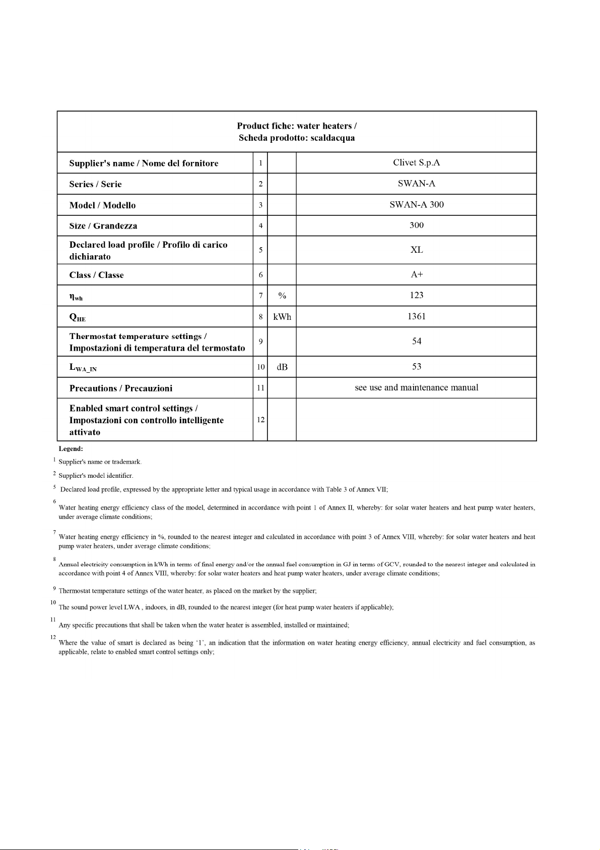
2. The product complies with the European Directive ErP, which includes the Commission Delegated Regulation (EU) N. 812/2013 and the Commission Delegated Regulation N.
814/2013, Average Climate, Heat Pump Water Heater
3. The product complies with the European Directive ErP, which includes the Commission Delegated Regulation (EU) N. 812/2013 and the Commission Delegated Regulation N.
814/2013, Warmer Climate, Heat Pump Water Heater
4. The product complies with the European Directive ErP, which includes the Commission Delegated Regulation (EU) N. 812/2013 and the Commission Delegated Regulation N.
814/2013, Colder Climate, Heat Pump Water Heater
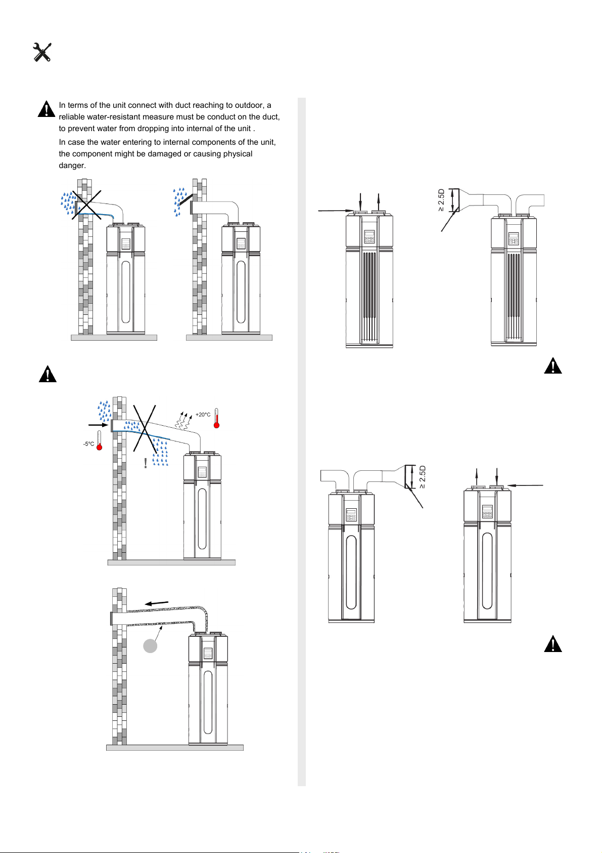
5. Data referred to completely ducted unit.
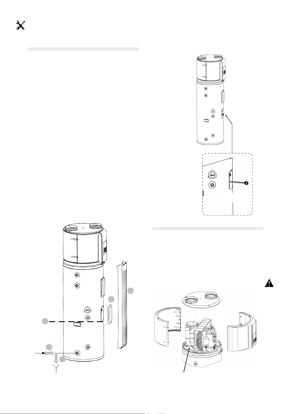
6. Maximum temperature that can be reached during Anti-legionella mode(Dinsifect)
*It contains fluorinated greenhouse gases
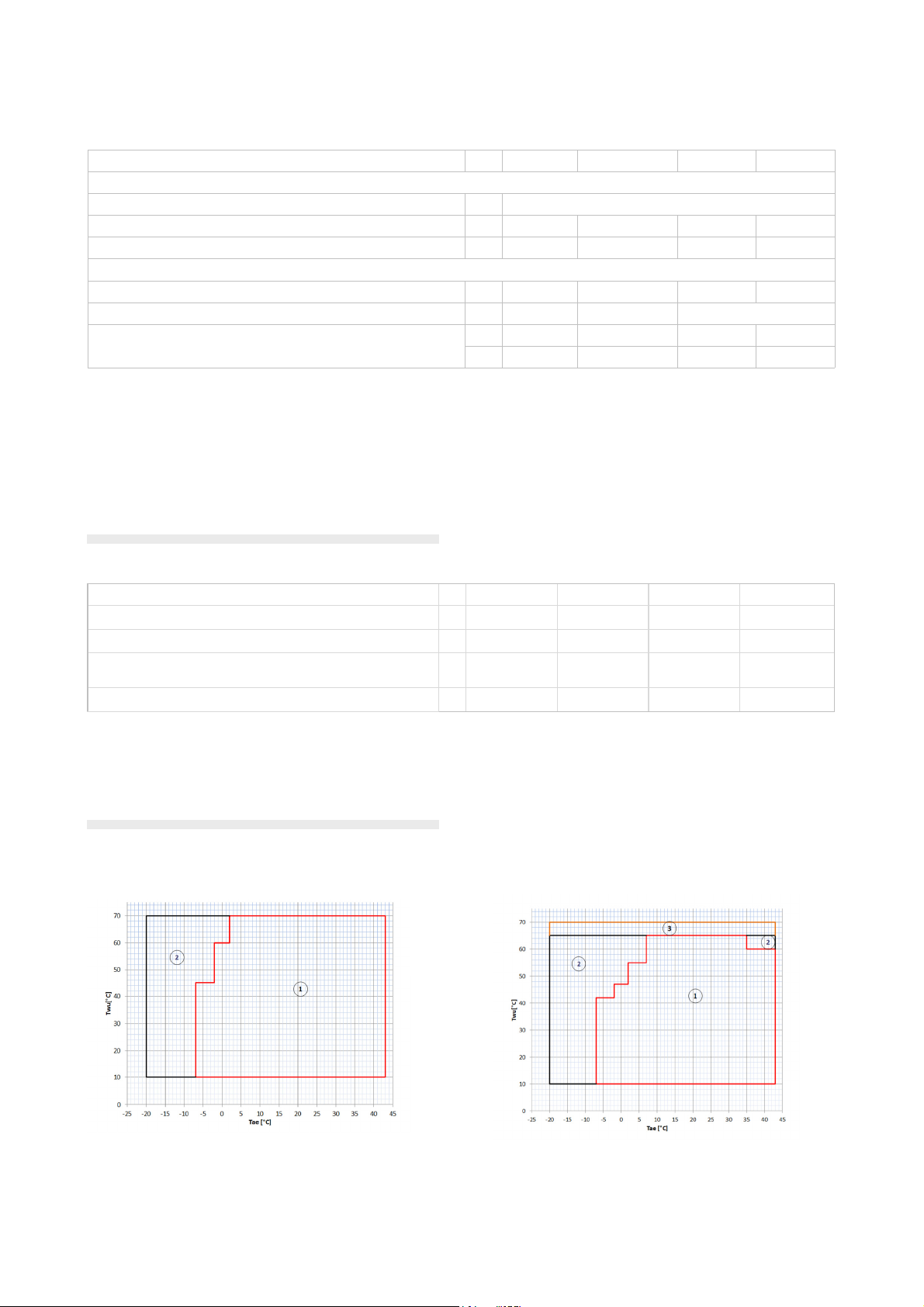
OPERATING LIMITS
ELECTRICAL DATA
1) Power supply 220-240/1/50 Hz
For power voltages other than the standard, contact the technical department
The units are conforming with the prescriptions of European Standards CEI EN 60204 and CEI EN 60335
Warning: when defining the correct size, verify that all absorption is compliant with current electrical supply
contracts in force in the country of installation
300 - 300S
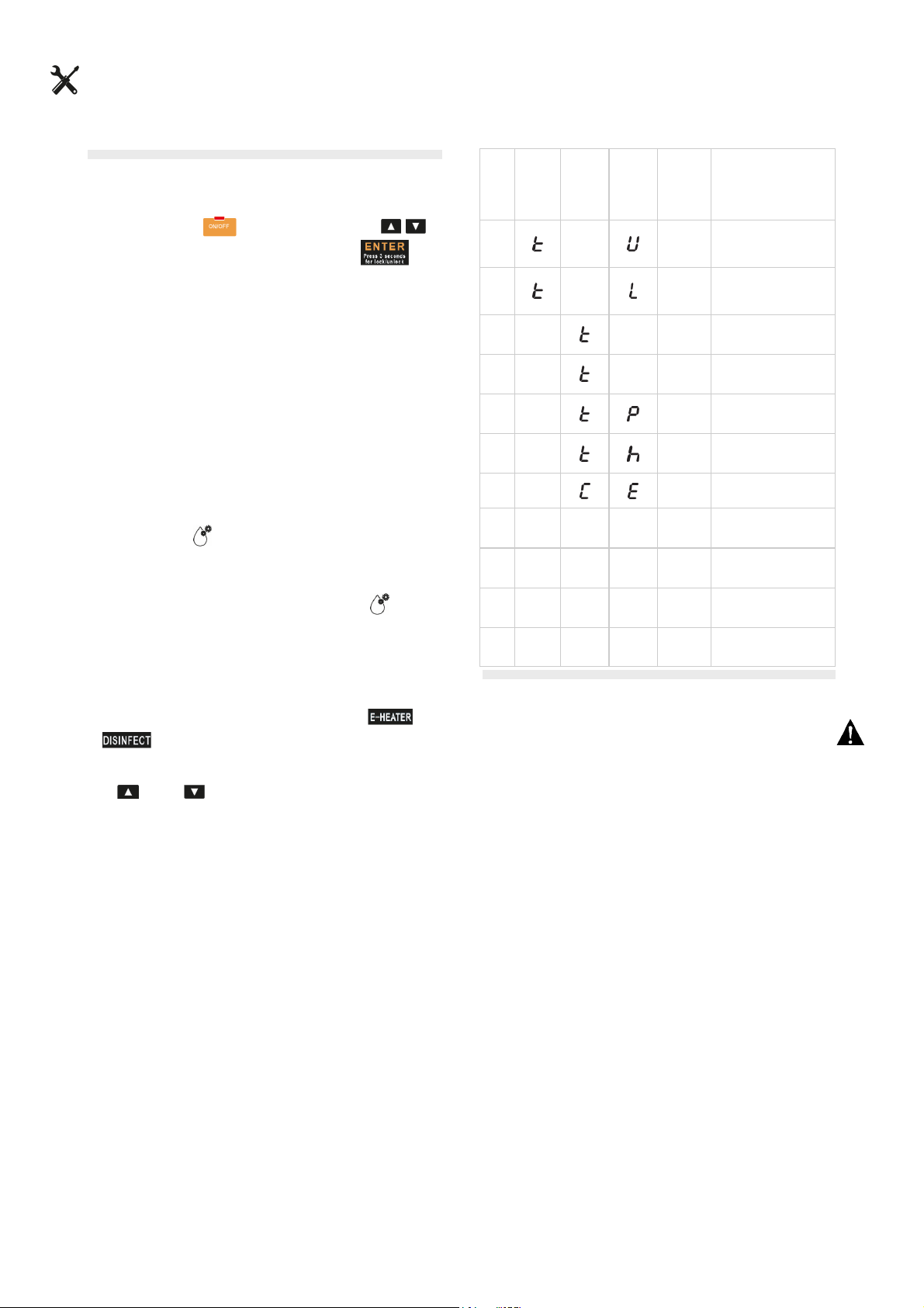
1. Use range of the heat pump
2. Use range of the electrical heating element
3. Use range of the electrical heating element only in Anti-Legionella mode
(Disinfect)
Twu [°C] water temperature in the accumulator
Tae [°C] air temperature at exchanger inlet
190 - 190S
Size 190 300 190S 300S
Power supply (1) V 220-240/1/50 220-240/1/50 220-240/1/50 220-240/1/50
F.L.A. - Current absorbed at the maximum allowed conditions A 16,1 16,5 16,1 16,5
F.L.I. - Power absorbed at full load (at the maximum allowed condi-
tions) kW 3,70 3,75 3,70 3,75
M.I.C - Maximum inrush current A 28,7 40,2 28,7 40,2
57
COMPAK KHPA 16 190
COMPAK KHPA 23 300
COMPAK KHP 16 190S
COMPAK KHP 23 300S
FRIGICOLL, S.A. BLASCO DE GARAY, 4-6, 08960 SANT JUST DESVERN, SPAIN
SANT JUST
DESVERN,
62
COMPAK
COMPAK KHPA 16 190
63
COMPAK
COMPAK KHP 16 190S
64
COMPAK
COMPAK KHPA 23 300
65
COMPAK
3


Need help? Post your question in this forum.

Forumrules


Report abuse

Libble takes abuse of its services very seriously. We're committed to dealing with such abuse according to the laws in your country of residence. When you submit a report, we'll investigate it and take the appropriate action. We'll get back to you only if we require additional details or have more information to share.

Product:

For example, Anti-Semitic content, racist content, or material that could result in a violent physical act.

For example, a credit card number, a personal identification number, or an unlisted home address. Note that email addresses and full names are not considered private information.

Forumrules

To achieve meaningful questions, we apply the following rules:

Register

Register getting emails for Kaysun COMPAK KHPA at:


You will receive an email to register for one or both of the options.


Get your user manual by e-mail

Enter your email address to receive the manual of Kaysun COMPAK KHPA in the language / languages: English as an attachment in your email.

The manual is 14.06 mb in size.


You will receive the manual in your email within minutes. If you have not received an email, then probably have entered the wrong email address or your mailbox is too full. In addition, it may be that your ISP may have a maximum size for emails to receive.

The manual is sent by email. Check your email

If you have not received an email with the manual within fifteen minutes, it may be that you have a entered a wrong email address or that your ISP has set a maximum size to receive email that is smaller than the size of the manual.

The email address you have provided is not correct.

Please check the email address and correct it.

Your question is posted on this page

Would you like to receive an email when new answers and questions are posted? Please enter your email address.


Info