590148
46
Zoom out
Zoom in
Previous page
1/188
Next page
Quick Reference Guide
SAFETY INFORMATION j
GENERAL INFORMATION j
HOW TO RIDE THE MOTORCYCLE j
MAINTENANCE AND ADJUS TMEN T j
APPENDIX j
MAINTENANCE RECORD j
This Quick Reference Guide will
assist you in finding the information
you’re looking for.
A Table of Contents is included after
the Foreword.
Whenever you see the symbols
shown below, heed their instructions!
Always follow safe operating and main-
tenance practices.
DANGER
DANGER indicates a hazardous
situation which, if not avoided,
will resu lt in death or serious in-
jury.
WARNING
WARNING indicates a hazardous
situation which, if not avoided,
could result in death or serious
injury.
NOTICE
NOTICE is used to address prac-
tices not related to personal in-
jury.
NOTE
NOTE ind icates informat ion that may
help or guide you in the operation or
service of the vehicle.
NOTICE
THIS PRODUCT HAS BEEN
MANUFACTURED FOR USE IN A
REASONABLE AND PRUDENT
MANNER BY A QUALIFIED OP-
ERATOR AND AS A VEHICLE
ONLY.
Foreword
Congratulations on your purchase of a new Kawasaki motorcycle. Your new mo-
torcycle is the product of Kawasaki’s advanced engineering, exhaustive testing,
and continu o us striving for superior reliability, safety and performance.
Please read this Owners Manual carefully before riding so that you will be
thoroughly familiar with the proper operation of your motorcycle’s controls, its fea-
tures, capabilities, and limitatio ns. This manua l offers ma n y safe riding tips, but its
purpose is not to pro vid e instruc tio n in all the techniqu es and skills required to ride
a motorcycle safely. Kawasaki strongly recommends that all operators of this vehi-
cle enroll in a motorcycle rider trainin g program to attain aw areness of the mental
and physical requirements necessary for safe m otorcycle operation.
To ensure a long, trouble-free life for your motorcycle, give it the proper care and
maintenance described in this manual. For those w ho would like more detailed in-
formation on their Kawasaki Motorcycle, a Service Manual is available fo r purchase
from any authorized Kawasaki motorcycle dealer. The Service Manual contains de-
tailed disassembly and maintenance information. Those who plan to do their own
work should, of course, be competent mechanics and possess the special tools
described in the Service Manual.
Keep this Owner’s Manual aboard your motorcycle at all times so that you can
refer to it whenever you need information.
This manual should be considered a permanent part of the motorcycle and should
remain with the motorcycle when it is sold.
All rights reserved. No part of this publication may be reproduced without our
prior written permission.
This publication includes the latest information available at the time of printing.
However, the r e may be minor differences between the actual product and illu stra -
tions and text in this manual.
All products are subject to change without prior notice or obligation.
KAWASAKI HEAVY INDUSTRIES, LTD.
Motorcycle & Engine Company
© 2014 Kawasaki Heavy Industries, L td. Aug. 4, 2014. (5)
(Australian model only)
TAMPERING WITH NOISE CONTROL SYSTEM
PROHIBITED
Owners are warned that the law may prohibit:
(a) The removal or rendering inoperativ e by any person other than for purposes
of maintenance, repair or replacement, of any device or element of design
incorporated into any new vehicle for the purpose of noise control prior to
its sale or delivery to the ultimate purchase r or while it is in u se; and
(b) The use of the vehicle after such device or element of design has been
removed or rendered inoperative by any person.
TABLE OF CONTENTS
SAFETY INFORMATION .................... 10
Read Owner’s Manual ..................... 10
Training ............................................ 10
Daily Checks and Periodic
Maintenance ................................. 10
Loading and Accessories
Information.................................... 11
Passenger .................................... 12
Baggage and Luggage ................. 13
Accessories .................................. 13
Other Load.................................... 14
If You are Involved in an Accident.... 14
Safe Operation................................. 15
Carbon Monoxide Hazard............. 15
Fueling.......................................... 16
Never Ride with Drugs or Alcohol. 16
Protective Gear and Clothing ....... 16
Safe R iding Techniques................ 17
Additional Considerations for High
Speed Operation ....................... 19
GENERAL INFORMATION................. 21
Specifications................................... 21
Serial Number Locations.................. 26
Location of Labels............................ 27
Location of Parts .............................. 39
Meter Instruments ............................ 42
Indicators ...................................... 43
Speedometer/Tachometer ............ 51
Coolant/Outside Temp erature
Meter ......................................... 52
Display Setting.............................. 55
Features ....................................... 61
Keys ................................................. 63
Ignition Switch/Steering Lock ........... 64
Right Handlebar Switches................ 66
Left Handlebar Switches .................. 67
Brake Lever Adjuster........................ 69
Clutch Lever Adjuster....................... 69
Fuel .................................................. 70
Fuel Requirements ....................... 70
Filling the Tank.............................. 74
Side Stand ....................................... 76
Center Stand.................................... 77
Seat.................................................. 77
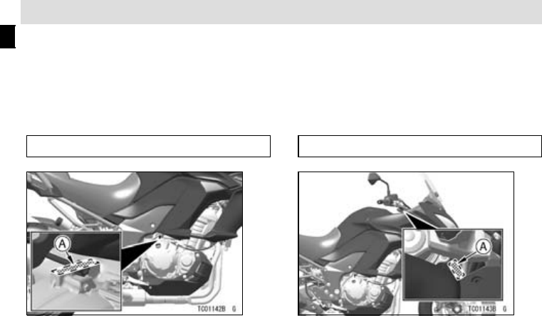
Tool Kit Case .................................... 79
Storage Compartment...................... 79
Rear View Mirrors ............................ 80
Windshield........................................ 81
Rear Carrier ..................................... 82
Tie Hooks ......................................... 84
Event Data Recorder........................ 84
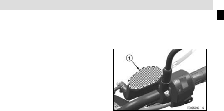
Electric Accessory Connectors ........ 85
HOW TO RIDE THE MOTORCYCLE .89
Break-In ........................................... 89
Starting the Engine .......................... 90
Jump Starting................................... 93
Moving Off........................................ 95
Shifting Gears .................................. 96
Braking............................................. 97
Anti-lock Brake System (ABS) ......... 98
Stopping the Engine......................... 101
Stopping the Motorcycle in an
Emergency ................................... 101
Parking............................................. 102
Kawasaki TRaction Control (KTRC). 104
Power Mode..................................... 108
KTRC and Power Mode
Combination ................................. 110
MAINTENANCE AND ADJUSTMENT 112
Daily Checks .................................... 114
Periodic Maintenance....................... 117
Engine Oil ........................................ 122
Coolant............................................. 125
Air Cleaner ....................................... 130
Throttle Control System ................... 131
Idle Speed........................................ 134
Clutch............................................... 135
Drive Chain ...................................... 136
Brakes.............................................. 141
Brake Light Switches........................ 143
Suspension System ......................... 144
Front Fork ..................................... 144
Rear Shock Absorber ................... 146
Setting Tables ............................... 149
Wheels ............................................. 153
Battery.............................................. 157
Headlight.......................................... 160
Fuses ............................................... 162
General Lubrication.......................... 163
Cleaning Your Motorcycle ................ 164
General Precautions..................... 164
Washing Your Motorcycle ............. 166
APPENDIX .......................................... 170
Storage ............................................ 170
Troubleshooting Guide..................... 173
Owner Satisfaction........................... 178
Environmental Protection................. 180
MAINTENANCE RECORD ................. 181
10 SAFETY INFORMATION
j
SAFETY INFORM ATION
Read Owners Manual
Read this Owner’s Manual care-
fully before riding so that you will be
thoroughly familiar w ith the proper op-
eration of your motorcycle’s controls,
its features, capabilities, and limita-
tions. This manual offers many safe
riding tips, but its purpose is not to pro-
vide instruction in all of the techniques
and skills required to ride a motorc ycle
safely.
Training
Kawasaki strongly recommends that
all operators of this vehicle complete a
suitable motorcycle rider training pro-
gram to learn the p roper skills an d tech-
niques necessary for safe m otorcycle
operation.
DailyChecksandPeriodic
Maintenance
It is important to keep your motorcy-
cle properly maintained and in safe rid-
ing condition. Inspect your m otorcy-
cle before every ride and carry out all
periodic maintenance. See the Daily
Checks section and the Periodic M ain-
tenance section in the MAINTENANCE
AND ADJUSTMENT chapter for more
informa tion.
WARNING
Failure to perform these checks
or to correct a problem before
operation may result in serious
damage or an accident. Always
perform daily checks before op-
eration.
SAFETY INFORM ATION 11
j
To ensure your motorcycle is ser-
viced using the latest servicing infor-
mation, it is recommended that an
authorized Kawasaki Dealer performs
the periodic maintenance a s directed
in the Owner’s Manual.
If you notice any irregu lar operat-
ing condition, have your motorcycle
thoroughly checked at an authorized
Kawasaki dealer as soon as possible.
Loading and Accessories
Information
WARNING
Incorrect loading, improper in-
stallation or use of accessories,
or modification of your motorcy-
cle may result in an unsafe riding
condition. Before you ride the
motorcycle,makesureitisnot
overloaded and that you have
followed these in structions.
Maximum Load
Weight of rider, passenger, baggage,
and accessories must not exceed 220 kg
(485 lb).
With the exception of genuine
Kawasaki Parts and Accessories,
Kawasaki has no control over the
design or application of accessories.
In some cases, improper installation
12 SAFETY INFORMATION
j
or use of a ccessories, or motorcycle
modification, will void the motorcycle
warranty; can negatively affect perfor-
mance, stability and sa fe ty; and can
even be illegal.
In selecting and using accessories ,
and in loading the motorcycle, you are
personally responsible for your own
safety and the safety of other persons
involved.
NOTE
Kawasaki Parts and Accessories
have been specially designed for
use on Kawasaki motorcycles. We
strongly recommend that all parts
and accessories you add to your
motorcycle be genuine Kawasaki
components.
Because a motorcycle is sensitive to
changes in weight and aerodynamic
forces, you must take extreme care in
carrying cargo, passengers and/or in
fitting additional accessories. The fol-
lowing general guidelines have been
prepared to assist you in making y our
determinations.
Passenger
1. Never carry more than one passen-
ger.
2. The passenger should only sit on the
pillion.
3. Any passenger should be thor-
oughly familiar with motorcycle op-
eration. The passenger can affect
control of the motorcycle by im-
proper positioning during cornering
and sudden movements. It is im-
portant that the passenger sits still
while the m otorcycle is in m o tion
and not interfere with the operation
of the motorcycle. Do not carry ani-
mals on your motorcycle.
SAFETY INFORMATION 13
j
4. Do not carry passengers unless
passenger footpegs are installed.
Instruct any passenger before riding
to keep his or her feet on the pas-
senger footpegs and hold on to the
operator or grab rail. Do not carry
a passenger unless he or she is tall
enough to reach the footpegs with
their feet.
Baggage and Luggage
1. All baggage should be carried as
low as possible to reduce the effect
on the m otorcycle’s center of grav-
ity. Baggage weight should also be
distributed equally on both sides of
the m otorcycle. Avoid carrying bag-
gage that extends beyond the rear
of the motorcycle.
2. Baggage should be securely at-
tached. Make sure that the baggage
will not move aroun d while you are
riding. Recheck baggage security
as often as possible (not while the
motorcycle is in m otion) and adjust
as necessary.
3. Do not carry heavy or bulky items
on a luggage rack. It is designed
for ligh t items, and overloading can
affect handling due to changes in
weight distribution and aerodynamic
forces.
Accessories
1. Do not install accessories or carry
baggage that impairs the perfor-
mance of the motorcycle. Make
sure that you have not adversely
affected any lighting components,
road clearance, banking capability
(i.e., lean angle), control operation,
wheel travel, front fork movement,
14 SAFETY INFORMATION
j
or any other aspects of the motor-
cycle’s operation.
2. Weight attached to the handlebars
or front fork will increase the mas s
of the steering assembly and can
result in an unsafe riding condition.
3. Fairings, windshields, backrests,
and other large items have the ca-
pability of adversely affecting stabil-
ity and handling of the motorcycle,
not only due to their weight, but
also due to the aerodynamic force
acting on these surfaces while the
motorcycle is in operation. Poorly
designed or installed items can re-
sult in an unsafe riding condition.
Other Load
1. This motorcycle is not intended to
be equipped with a sidecar or to be
used to tow any trailers or other ve-
hicles. Kawasaki does not manu-
facture sidecars or trailers for mo-
torcycles and cannot predict the ef-
fects of such accessories on han-
dling or s ta bility, but can only warn
thattheeffectscanbeadverseand
that Kawasaki cannot assume re-
sponsibility for the results of such
unintended use of the motorcycle.
2. Furthermore, any adverse effects on
motorcycle components caused by
the use of such accessories will not
be remedied under warranty.
If You are Involved in an
Accident
Make sure of your own safety first.
Determine the severity of any injuries
and call for emergency a ssistance if
needed. Always follow applicable laws
SAFETY INFORMATION 15
j
and regulations if any other person, ve-
hicle or property is involve d.
Do not attempt to continue riding
without first evaluating you r motorcy-
cle’s condition. Inspect for fluid leaks,
check critical nuts and bolts, and check
the handlebars, control levers, b rakes,
and wheels for damage and proper
function. Ride slowly and cautiously
- your motorcycle may have suffered
damage that is not immediately appar-
ent. Have your motorcycle thoroughly
checked at a Kawasaki dealer as soon
as possible.
Safe Operation
The following should be carefully ob-
served for safe and effective vehicle
operation.
Carbon Monoxide Hazard
DANGER
Exhaust gas contains carbon
monoxide, a colorless, odor-
less poisonous gas. Inhaling
carbon monoxide can cause
serious brain injury or death.
DO NOT run the engine in en-
closed areas. Operate only in a
well-ventilated area.
16 SAFETY INFORMATION
j
Fueling
WARNING
Gasoline is extremely flammable
and can be explosive under
certain conditions. To avoid a
possible fire or explosion, turn
the ignition switch off. D o not
smoke. Make sure the area is
well ventilated and free from any
source of flame or sparks; this
includes any appliance with a
pilot light.
Never Ride with Drugs or Alcohol
Alcohol and drugs impair your judg-
ment and reaction time. Never con-
sume alcohol or drugs before or while
riding motorcycles.
Protective Gear and Clothing
Helmet
Kawasaki strongly recommends both
the operator and passenger wear a hel-
met even if this is not a legal require-
ment.
- Make sure that your helmet fits cor-
rectly and is properly fastened.
- Choose a m ot orcycle helm et that
meets the safety standards appli-
cable to your country. Ask y our
motorcycle dealer to advise you if
necessary.
SAFETY INFORMATION 17
j
Eye Protection
Always use eye protection. If your
helmet does not have a visor installed,
wear goggles.
Gloves
Wear gloves which have suitable
protection for your hands, especially
against abrasion.
Clothing
Wear protective clothing.
- Wear b rig h t, highly visible clothing
that allows freedom of movement
to suit your riding style.
- Always wear a long- sleeved jac ket
and long tro users w h ich are abra-
sion resistant and keep you warm.
- Avoid wearing clothes which have
loose cuffs or other fastenings
which could interfere with the con-
trols of your motorcycle.
Boots
Wear proper protective boots that fit
properly and do not interfere with gear
shifting or braking.
Safe Riding Techniques
Keep Hands on Handlebars
When riding always keep both hands
on the handlebars and both feet on the
footpegs. Removing your hands from
the handlebars or feet from the foot-
pegs while riding can be hazardous. If
you remove even one hand or foot, you
reduce your ab ility to c on trol the motor-
cycle.
Look Over Your Shoulder
Before changing lanes, look over
your shoulder to make sure the way
is clear. Do not rely so lely on the rear
18 SAFETY INFORMATION
j
view mirror; you may misjudge a vehi-
cle’s distance and speed, or you may
not see it at all.
Accelerate and Brake Smoothly
In general your actions should be
smooth as sudden acceleration, brak-
ing or turning may cause loss of control,
especially when riding in wet conditions
or on loose road surfaces, when the
ability to maneuver will b e reduced.
Select Correct Gear Speeds
When going up steep slopes, shift to
a lower gear so that there is power to
spare rather than overloading the en-
gine.
Use Both Front and Rear Brakes
When applying the brakes, use both
the front and rear brakes. Applying
only one brake for sudden braking may
cause the motorcycle to skid and lose
control.
Use Engine Brake
When going down long slopes, help
control vehicle speed by closing the
throttle so that the engine can act as an
auxiliary brake. Use the front and rear
brakes for primary braking.
Riding in Wet Conditions
Rely more on the throttle to c ontrol
vehicle s peed and less on the front and
rear brakes. The throttle should also be
used judiciously to avoid skidding the
rear wheel from too rapid acceleration
or deceleration.
Braking perform ance is also reduced
in wet conditions. Carefully ride at a
slow speed and apply the brakes sev-
eral times to help dry and restores them
to normal operating performance.
Lubricate the drive chain after wet
-weather riding to prevent rust and cor-
rosion.
SAFETY INFORMATION 19
j
Ride Prudently
Riding at the proper speed and avoid-
ing unnecessarily fast acceleration are
important not only for safety and low
fuel consumption but also for lon g ve-
hicle life and quieter operation.
Riding on Rough Roads
Exercise caution, slow down, a nd
grip the fuel tank with the knees for
better stability.
Acceleration
When quick acceleration is neces-
sary to pass another vehicle, shift to
a lower gear to obtain the necessary
power.
Downshifting
To avoid engine damage and rear
wheel lock-up do not downshift at high
rpm.
Avoid Unnecessary Weaving
Unnecessary weaving jeopardizes
the safety of both the rider and other
motorists.
Additional Considerations for
High Speed Operation
WARNING
Handling characteristics of a
motorcycle at high speeds may
vary from those you are familiar
with at legal highway speeds.
Do not attempt high speed oper-
ation unless you have received
sufficient training and have the
required sk il ls.
Do not operate at high speeds on
public roads.
20 SAFETY INFORMATION
j
Brakes
The importance of the brakes, es-
pecially during high speed operation,
cannot be overemphasized. Check to
see that they are correctly adjusted and
functioning properly.
Steering
Looseness in the steering can cause
loss of control. Ch eck to see that the
handlebars turns freely but has no play.
Tires
High speed operation is hard on tires,
and good tires are crucial for safe rid-
ing. Examine their overall condition, in-
flate them to the proper pressure, and
check the wheel balance.
Fuel
Have sufficient fuel for the high fuel
consumption during high speed opera-
tion.
Engine Oil
To avoid engine seizure and resulting
loss of control, make sure that the oil
level is at the upper level line.
Coolant
To avoid overheating, check tha t th e
coolant level is at the upper level line.
Electrical Equipment
Make sure that the headlight,
tail/brake light, turn signals, horn, etc.,
all work properly.
Miscellaneous
Make sure that all nuts and bolts are
tight and that all safety related parts are
in good condition.
GENERAL INFORMATION 21
j
GENERAL INFORMATION
Specifications
PERFORMAN
CE
Maximum Horsepower
88 kW (120 PS) @9 0 00 r/min (rpm)
Maximum Torque
102.0N·m(10.4kgf·m,75ft·lb)@7500r/min(rpm)
Minimum Turning Radius
3.0 m (118
in.)
DIMENSIO
NS
Overall
Length
2240mm(
88.19 in.)
Overall
Width
895 mm (3
5.2 in.)
Overall
Height/High Position
1400mm(
55.12 in.)/1 465 mm (57.68 in.)
Wheelbase
1520mm
(59.84 in.)
Road C l
earance
150 mm (
5.91 in.)
Curb Mass
250 kg (
551 lb)
(ID, SE
A-B2)
249 kg (
549 lb)
ENGIN
E
Type
DOHC,
4-cylinder, 4-stroke, liquid-cooled
22 GENERAL INFOR MATION
j
Displacement 1 043 cm³ (63.64 cu in.)
Bore × Stroke 77.0 × 56.0 mm (3.03 × 2.20 in.)
Compression Ratio 10.3:1
Starting System Electric starter
Cylinder Numbering M ethod Left to right, 1-2-3-4
Firing Order 1-2-4-3
Fuel System FI (Fuel Injection)
Ignition System Battery and coil (transistorized ig nition)
Ignitio
nTiming
(Electronically advanced)
10° BTDC @1 100 r/min (rpm) 40.2° BTDC @5 200
r/min (rpm)
Spark Plu g:
Type
NGK CR9EIA-9
Gap 0.8 0.9 mm (0.031 0.035 in.)
Lubrication System Forced lubrication (wet sump)
Engine Oil:
Type
API SG, SH, SJ, SL or SM with JASO MA, MA1 or MA2
Viscosity
SAE 10W-40
Capacity 4.0 L (4.2 US qt)
Coolant Capacity 2.6 L (2.7 US qt)
GENERAL INFORMATION 23
j
TRANSMISSION
Tra nsmissi on Type 6-speed, constant mesh, retur n shift
Clutch Type Wet, multi disc
Driving System Chain drive
Primary Reduction Ratio 1.627 (83/51)
Final R eduction Ra tio 2.867 (43/15)
Overall Dri ve Ratio 4.471 (Top gear)
Gear Ratio: 1st 2.692 (35/13)
2nd 1.950 (39/20)
3rd 1.529 (26/17)
4th 1.304 (30/23)
5th 1.136 (25/22)
6th 0.958 (23/24)
FRAME
Caster 27°
Trail 106 mm (4.17 in.)
24 GENERAL INFOR MATION
j
Tire Size: Front 120/70ZR17 M/C (58W)
Rear 180/55ZR17 M/C (73W)
Rim S ize: Front J17M/C × MT3.50
Rear J17M/C × MT5.50
Fuel Tank Capacity 21 L (5.5 US gal)
Brake Fluid: Front DOT4
Rear DOT4
ELECTRICAL EQUIPMENT
Battery 12V8Ah(10HR)
Headlight: High Bea m 12 V 55 W × 2
Low Beam 12 V 55 W
Tail/Brake Light LED
ID: Indonesia Model
SEA-B2: Southeast Asia B2 Model
Even if one of LED (Light Emitting Diode) tail/brake light or headlight does not go
on, consult with an authorized Kawasaki dealer.
GENERAL INFORMATION 25
j
Specifications are subject to change without notice, and may not apply to every
country.
26 GENERAL INFOR MATION
j
Serial Number Locations
The eng in e and frame serial numbers are used to reg ister the m ot orcycle. The y
are the only means of identifying your particular machine from others of the same
model type. These serial numbers ma y b e needed by your d ealer when ordering
parts. In the event of theft, the investigating authorities will require both numbers
as well as the model type and any peculiar features of your machine that can help
them identify it.
Engine No.
A. Engine Number
Frame No.
A. Frame Number
GENERAL INFORMATION 27
j
Location of Labels
All warning labels which are on your
vehicle are repeated here. Read labels
on your vehicle and understand them
thoroughly. They contain information
which is important for your safety and
the safety of anyone else who m ay op-
erate your vehicle. Th eref ore, it is very
important that all warning labels be on
your vehicle in the locations show n. If
any label is missing, damaged, or worn,
get a replacement from your Kawasaki
dealer and install it in the correct posi-
tion.
NOTE
The sample warning labels in this
section have part numbers to help
you and your dealer obtain the cor-
rect replacement.
Refer to the actual vehicle label for
model spe cific data grayed o ut in the
illustration.
1. Brake Fluid (Front)
28 GENERAL INFOR MATION
j
2. Brake Fluid (Rear)
3. Battery Poison/Danger
4. Rear Shock Absorber Warning
GENERAL INFORMATION 29
j
5. Radiator Cap Dan ger
*6. Fuel Level
7. Fuel Notice
*8. Helmet Wearing
****8. Safety Riding Notice
**9. Noise Emission Control Information
10. Important Drive Chain Information
11. Tire and Load Data
*: only on Thailand model
**: only on Brazil model
****: only on Indon esia mode l
30 GENERAL INFOR MATION
j
*12. Vacuum Hose Routing Diagram
***13. Noise Test Information
****13. Coolant Notice
14. Rear Carrier Load Limit Warnin g
*: only on Thailand model
***: only on Australian, Malaysia and
Southeast A sia B2 models
****: only on Indonesia m od el
GENERAL INFORMATION 31
j
1)
2)
3) Except Brazil model
32 GENERAL INFOR MATION
j
3) only on Brazil model 4) Except Brazil model
GENERAL INFORMATION 33
j
4) only on Brazil model
5)
6) only on Thailand model
7) Except Thailand, Brazil and
Indonesia models
34 GENERAL INFOR MATION
j
7) only on Thailand model
7) only on Brazil model
7) only on Indonesia model
8) only on Thailand model
GENERAL INFORMATION 35
j
8) only on Indonesia model
9) only on Brazil model
10) Except Brazil and Indonesia
models
10) only on Brazil model
36 GENERAL INFOR MATION
j
10) only on Indonesia model
11) Except Brazil and Indonesia
models
11) only on Brazil model
11) only on Indonesia model
GENERAL INFORMATION 37
j
12) only on Thailand model 13) only on Australian model
13) only on Malaysia and Southeast
Asia B2 models
38 GENERAL INFOR MATION
j
13) only on Indonesia model 14)
1. Warning
2. Read Owner’s Manual, see pag e 10
3. Rear carrier load, see page 82
GENERAL INFORMATION 39
j
Location of Parts
1. Rear View Mirrors
2. Starter Lo ckou t Switch
3. Windshield Adjusting Knobs
4. Meter Instrument
5. Brake Fluid Reservoir (Fro nt)
6. Clutch Lever
7. Left Handlebar S witches
8. Spring Preload Adjuster
9. Ignition Sw it ch/Steering Lock
10. Rebound Damping Fo rce Adjuster
11. Right Handlebar Switches
12. Throttle Grip
13. Front Brake Lever
40 GENERAL INFOR MATION
j
1. Headlight
2. Spark Plugs
3. Air Cleaner
4. Fuel Tank
5. Seat
6. Tie Hooks
7. Turn Signal Lights
8. License Plate Light
9. Seat Lock
10. Chain Adjuster
11. Drive Chain
12. Center Stand
13. Side Stand
14. Shift Pedal
15. Side Stand Switch
16. Oil Filter
17. Front Fork
GENERAL INFORMATION 41
j
1. Tail/Brake Light
2. Spring Preload Ad juster
3. Brake Fluid Reservoir (Rear)
4. Battery
5. Rear Shock Absorber
6. Fuse Boxes
7. Fuel Tank Cap
8. Coolant Reserve Ta nk
9. Brake Discs
10. Brake Calipers
11. Oil Level Inspection Window
12. Idle Adjusting Screw
13. Rear Brake Pedal
14. Rear Brake Lig ht Switch
15. Rebound Damping Fo rce Adjuster
16. Muffler
42 GENERAL INFOR MATION
j
Meter Instruments
1. Tachometer
2. Upper Meter Button
3. Lower Meter Button
4. Multifunction Meter
5. Fuel Gauge
6. Economical Riding Indicator
7. Multifunction Display
-Odometer
- Trip Meter A/B
- Current Mileage/Average Mileage/Cruising
Range
-Clock
8. Speedometer
9. KTRC Mode Indicator
10. Coolant/Outsid e Temperature Meter
11. Power Mode In dicat or
When the ignition switch is turned on , all LCD
functions are shown for a few seconds, then the
multifunction meter turns to operational mode.
GENERAL INFORMATION 43
j
Indicators
1. Left Turn Signal Indicator (Green)
2.
Right Turn S ignal Indicator (Green)
3.
High Beam Indic ator (Blue)
4.
Neutral Indicator (Green)
5.
KTRC Warning Indicator (Yellow)
6.
KTRC Indicator (Yellow)
7.
ABS Indicator (Yel low )
8.
Engine Warning Indicator (Yello w)
9.
Immobilizer Warning I ndi cator
10.
Oil Pressure Warning Indicator
11.
Warning Indicator/Immobilizer Indicator
(Red)
12.
Coolant Temperature Warning Indicato r
13.
Battery Warning In dicator
14.
Fuel Level Warning Indicator
44 GENERAL INFOR MATION
j
Indicator Initial Operation
When the ignition switch is turned on,
all indicators go on/off as shown in the
table. If any indicator does not operate
as shown, have it checked by an autho-
rized Kawasaki dealer.
ON
Indicators
ON: When i gnition switch is turned on.
: After a few seconds
:Whenenginestarts.
: G oes on.
:Goesoff.
*:
goes off shorty after the
motorcycle starts m oving.
GENERAL INFORMATION 45
j
When Warning Indicators Go On
or Blink
When warning indicators appear, there could be a problem with vehicle function.
Follow actions in the table after stopping the vehicle in a safe place.
*: The numbers in this column corresponds to reference numbers on page 43.
*No.
Indi-
cators
Status
Actions
5
ON
The KTRC system is not working and the KTRC and
Power mode indicators
*1
blink. Have the system checked
by an authori z ed Kawasaki dealer.
7
ON
*2
The A BS has malfunctioned. ABS will not work but
conventional b r akes function. Have the ABS checked by
an authorized Kawasaki deale r.
ON
The DFI system has malfunctioned. Have it checked by
an authorized Kawasaki deale r.
8
Blink
If this indicator blinks while pushing the starter button, the
vehicle-down sensor has been tripped and the engine
cannot be s tarted. Turn the ignition switch off and then
back on to start the engine.
46 GENERAL INFOR MATION
j
*No.
Indi-
cators
Status
Actions
11
9
Blink
The i mmobilizer system has malfunctioned. These
indicators blink if an improperly coded key is used or
if there is a miscommunication b etwe en the antenna
and key. Have the immobilizer system checked by an
authorized Kawasaki dealer.
11
10
ON
These indicators go on whenever the oil pressure is
dangerously low or the ignition switch is in the
position with the engine not running. If these indicators
go on when the engin e speed is above idle, stop th e
engine immediately and check the engi ne oil level. If
the amount of engi ne oil is insufficient, add engine oil.
If the oil level is g ood, have the engine checked by a n
authorized Kawasaki dealer.
11
12
ON
These indicators go on whenever the coolant temperature
rises to about 115°C (239°F). R efer to the Coola nt/Outside
Tempe r ature Meter section for more information and
follow instructions in it.
GENERAL INFORMATION 47
j
*No.
Indi-
cators
Status
Actions
11
13
ON
These indicators go on if the battery voltage is less than
11.0 V or m ore than 16.0 V. If they go on, charge the
battery. If they still go on after charging the battery,
have the battery and/or charging system checked by an
authorized Kawasaki dealer.
Blink
The lowe s t segment and fuel level w arning indicator
blink in t he multifunction disp lay when approximately
3.9 L (1.0 US gal) of usable fuel remains. Refuel at the
earliest opportunity. If the vehicle is on the side stand, the
warning indicator cannot esti m ate the amount of fuel in
the tank. Stand the vehicle upright to check the fuel level.
14
Blink (including
all segments)
The fuel level warning system has malfunctioned. Have
the fuel level warning system checked by an authorized
Kawasaki dealer.
48 GENERAL INFOR MATION
j
*1:
Refer to the Meter Instruments section for indicator position.
*2:
ABS indicato r may go on:
After c ontinuous riding on a rough r oad.
When the engine is started with the stand raised and the transmission engaged,
and the rear wheel turns.
When accelerating so abruptly that the front wheel leaves the ground.
When the ABS has been subjec ted to strong electrical interference.
When tire pressure is abnormal. Adjust tire pressure.
When a tire different i n size from the s tandard size is being used. Replace with
standard s ize.
When the wheel is deformed. Replace the wheel.
If this happens, fir st turn the ignition switch off, and th en back on, and ride the
motorcycle at 5 km/h (3.1 mph) or more. The AB S indicator should then go off. If it
does not, have the ABS checked by an authorized Kawasaki dealer.
GENERAL INFORMATION 49
j
Other Indicators
*No.
Indicators
Status
1
When the turn signal switch is pushed to the left, this indicator blinks.
2
When the turn signal switch is pushed to the right, this indicator blinks.
3
When the headlight is on high beam, this indicator goes on.
4
When the transmission is in neutral, this indicator goes on.
6
When the KTRC functions, this indicator goes on.
11
When the ignition sw itch is turned o ff, this indicator wil l start blinking
*1
,
which indicates that the immobilizer system is functioning. After 24
hours, the red warning indicator/immobilizer ind icator will stop blinking.
However, the immobilizer system is still functioning.
50 GENERAL INFOR MATION
j
*1: The red warning indicator/immobilizer indicator blinking mode can be set to either
on or off.
To sto p the red warning indicator/immobilizer indica t or bl inking, turn the ignition
switch off and then, within twenty seconds, push and hold the upper meter and
lower meter buttons simultaneously for more than two second s.
When the battery is conne c ted, red warning indicator/immobilizer indicator
defaults to blinking mode.
When the battery voltage is low (below 12 V), the red warn ing
indicator/immobilizer indicator automatically stops blinking to prevent excessive
battery discharge.
GENERAL INFORMATION 51
j
Speedometer/Tachometer
A. Speedometer
B. Tachometer
C. Red Zone
Speedometer
The speedometer is digital and can
be set for km/h or mph.
The unit setting can be changed ac-
cording to local regulations. Make sure
the unit setting (km/h or mph) is cor-
rectly displayed b e fo re riding.
Refer to the Unit Setting in the Dis-
play Setting section.
Tachometer
The tachometer shows the engine
speed in revolutions per minute (r/min,
rpm).
NOTICE
Engine speed should not be al-
lowed to enter the red zone; op-
eration in the red zone will over-
stress the engine and may cause
serious engine damage.
When the ignition switch is turned
on, the tachometer needle momentar-
ily sweeps from the minimum to the
maximum reading, then back the mini-
mum reading to check its operation. If
52 GENERAL INFOR MATION
j
the tachometer does not operate cor-
rectly, have it checked by an authorized
Kawasaki dealer.
Coolant/Outside Temperature
Meter
This meter shows the coolant tem-
perature or outside temperature.
Pushthelowermeterbuttontose-
lect the display modes. The display
modes can be shifted in the following
order.
NOTE
You can also select desired display
modes with the multifunction button
on the left handlebar switches.
A. Lower Button/Lower Meter Button
B. Flow when pushing lower or lower meter
button
GENERAL INFORMATION 53
j
NOTE
The coolant/outside te mperature me-
ter and clock cannot be shifted while
adjusting the clock.
Coolant Temperature Meter
The coolant temperature meter in-
dicates temperature of the engine
coolant.
A. Coolant Temperature Meter
If the coola nt temperature is below
40°C (104°F), “– –” is disp layed.
If the coolant temperature rises to
above 115°C (239°F) and below 120°C
(248°F), the numerical value of the
current coolant temperature starts
blinking, the warning indicator/immobi-
lizer indicator and coolant temperature
warning indicator also go on. This
warns the operator that the coolant
temperature is high.
54 GENERAL INFOR MATION
j
A. Coolant Temp erature Warning Indicator
B. Warn ing Indicat or/Immobilizer Indicator
(Red)
If the coolant temperature rises to
120°C (248°F) or more, “HI” is dis-
played and starts blinking, the warning
indicator/immobilizer indicator and
coolant temperature warning indicator
also go on. Stop the engine and check
the coolant level in the reserve tank
after the engine cools down. If the
amount of the coolant is insufficient,
add c oolant to the res erve tank. If the
coolant level is good, have the cool-
ing system checked by an authorized
Kawasaki dealer.
NOTICE
Stop the engine if the coolant
temperature shows “HI.” Pro-
longed engine operation will
result in severe engine damage
from overheating.
NOTE
The outside temperature meter shift
to the coolant temperature meter au-
tomatically if the coolant temperature
rises to above 115°C (239°F).
When the battery is reconnected, the
meter display is set to coolant tem-
perature meter by default.
GENERAL INFORMATION 55
j
Outside Temperature Meter
This display shows the outside tem-
perature by numerical value. The out-
side temperature display is renewed
every 5 seconds.
A. Outside Temperature Meter
NOTE
The outside temperature can be dis-
played from –20°C (–4°F) to 60°C
(140°F).
The outside temperature may not
be d isp la yed corre ctly in this meter
whenthespeedis20km/h(12mph)
or less, or the outside temperature
sensor gets wet. The display value
of the outside temperature does not
increase when the speed is 20 km/h
(12mph)orless.
The outside temperature meter shift
to the coolant temperature meter au-
tomatically if the coolant temperature
rises to above 115°C (239°F). In this
case, the meter cannot be shifted to
the outside temperature meter until
the warning indicator goes off.
Display Setting
Meter Buttons and Multifunction
Buttons
The meter buttons and multifunction
buttons on the left handlebar switches
areusedtooperatethevariousfunc-
tions displayed in the multifunction me-
ter.
56 GENERAL INFOR MATION
j
WARNING
For safety, do not operate the
meter buttons while riding the
motorcycle.
A. Upper Meter Button
B. Lower Meter Button
C. Multifunction Button s
D. Upper Button
E. “SEL” Button
F. Lower Button
With these buttons you can select de-
sired functions. Refer to each section
for procedure for selection.
Functions
Meter
Buttons
Multi-
function
Buttons
Multifunction Displa y
Mode
Coolant/Outside
Temperat ure
Unit Setting
KTRC Mode
Power Mod
e
Multifunction Display
Push the upper meter button to se-
lect the display modes. The display
modes can be shifted in the following
order.
GENERAL INFORMATION 57
j
NOTE
The multifunction display is d is-
played in the unit depending on the
unit mode setting.
You can also select desired display
modes with th e multifunc tio n button
on the left handlebar switches.
A. Upper Button/Uppe r Meter Butto n
B. Flow when pushing upper or upper meter
button
58 GENERAL INFOR MATION
j
Odometer
The odometer shows the total dis-
tance. This meter cannot be reset.
NOTE
When the figures come to 999999,
the display is stopped and locked.
Trip Meter
To reset the trip meter:
Push the upper meter button or upper
buttonandholditinuntilthedisplay
turns to 0.0.
NOTE
When the trip meter reaches 9999.9
while riding, the meter resets to 0.0
and continues counting.
Current Mileage
The current mileage display is re-
newed every 4 seconds.
NOTE
When the ignition switch is turned on,
the numerical value shows “– –.–.”
GENERAL INFORMATION 59
j
After a few seconds of riding the nu-
merical value is displayed.
Average Mileag e
This dis play mode shows the ave r-
age fuel consumption from the reset.
The average mileage display is re-
newed every 5 sec on ds.
To re set the average mileage:
Push the upper meter button or upper
button and hold it in until the average
mileage values reset s to “– –. –.”
NOTE
When the battery is disconnected,
the average mileage resets to “– –.–.”
After resetting the average mileage,
the numerical value is not displayed
until the vehicle has travelled 100 m
(328 ft).
Cruising Range
This display shows the cruising range
by numerical value, and indicates the
cruising range fro m the remaining fuel
in the fuel tank. This cruising range
display is renewed every 20 seconds.
NOTE
The cruising range value is no longer
shown if the fuel level gets too low
after the fuel level warning indicator
starts blinking.
60 GENERAL INFOR MATION
j
To recover the cruising range value
display add fuel to at leas t the level
needed for the fuel level warning in-
dicators to stop blinking. The cruis-
ing range may still be displayed with
a low fuel level, but it w ill not be ac-
curate until enough fuel is added to
stop the fuel level warning indicator
from blinking.
Clock
To adjust the clock:
Push the upper meter button or upper
button to select the clock.
Push the up per meter button and
hold it until both the hour and minute
displays blink.
Push the lower meter button to select
the h our or minute digits.
Push the upper meter button to ad-
just the hour o r minute digits.
To finish the adjustment, push the up-
per meter button when both the h our
and minute digits blin k.
NOTE
When the battery is disconnected,
the clock is reset to 1:00 and starts
working again when the battery is
connected.
GENERAL INFORMATION 61
j
Unit Setting
A. Odometer
B. Units
Display the o dometer in the multi-
function display.
Push the lower meter button while
pushing the upper meter button to se-
lect the meter display units. The dis-
play units can be shift ed in the follow-
ing order.
Features
Economical Riding Indicator
When riding the motorcyc le effi-
ciently, the economical riding indicator
appears on the multifunction meter to
indicate favorable fuel consumption.
Monitoring the economical riding indi-
cator can help the rider maximize fuel
efficiency.
62 GENERAL INFOR MATION
j
A. Economical Rid ing Indicator
WARNING
Failing to properly observe the
road ahead increases the chance
of an accident resulting in se-
vere injury or death. Do not con-
centrate on the economical rid-
ing indicator by taking your eyes
off the road; observe using pe-
ripheral vision.
Fuel Gauge
The fuel in the fuel tank is shown by
the number of segments displayed.
A. Segments
B. F (Full)
C. E (Empty)
NOTE
When the fuel tank is full, all the seg-
ments are displayed. As the fuel
level in the tank goes down, the seg-
ments disappear one by one from F
(full) to E (empty).
When the fuel level warning indicator
and lowest segment blink, refer to the
GENERAL INFORMATION 63
j
“When Warning Indicators Go On or
Blink” of Indicators in this chapter.
Power Mode Indicator
Refer to the Power Mode section in
the HOW TO RIDE THE MOTORCY-
CLE chapter.
KTRC Mode Indicator
Refer to the Kawasaki TRaction Con-
trol (KTRC) section in the HOW TO
RIDE THE MOTORCYCLE chapter.
Keys
This motorcycle is equipped w ith an
immobilizer system that makes the key
system secure electronically. This mo-
torcycle has two ignition keys.
One k ey should be stored and an-
other one should be used daily. If you
want to register an additional key to the
immobilizer system, at least one of al-
ready registered keys is required.
When the additional key will be regis-
tered, all of your keys are needed.
They should be re-registered to the
ECU at that time. Bring all of your keys
to an authorized Kawasaki de aler.
Up to five keys can register to the
ECU.
If an ignition key is lost, it is strongly
recommended to have your all keys re
-registered at an authorized Kawasaki
dealer to prevent th e possibility of theft.
If you lose all of your keys, you must
replace the ECU, etc. In any of the
above cases, please contact an autho-
rized Kawasaki dealer.
64 GENERAL INFOR MATION
j
NOTICE
The following can damage keys
and prevent the engine from be-
ing started, therefore, do not:
Put two keys of a ny immobi-
lizer system on the same key
ring.
Submerge a key in water.
Expose a key to excessively
high temperature.
Place a key close to magnets.
Place heavy item on a key.
Grind a key or alter its shap e.
Disassemble the plastic part of
akey.
Drop a key and/or apply
shocks to it.
EC Directive Compliance
This immob ilize r system complie s
with the R & TTE (Radio equipment and
telecommunications terminal equip-
ment and the mutual recognition of
their conformity) Directive.
Ignition Swit ch/Steering
Lock
This is a four-position, key-operated
switch.
The key can be removed when it is in
the
, or position.
GENERAL INFORMATION 65
j
ON
Engine can be started.
All electrical equipment can
be used.
Key cannot be removed.
OFF
Engine off.
Electrical equi pment is off.
Key can be remo ved.
LOCK
Steering locked.
Engine off.
Electrical equi pment is off.
Key can be remo ved.
LOCK
Steering locked.
Engine off.
Hazard lights can be used.
Key can be remo ved.
For locking:
1. Turn the handlebars fully to the left.
2. Push the key down in the
po-
sition and turn it to
or .
WARNING
Turning the ignition switch to
the
position while riding
the motorcycle shuts down the
entire electrical system (head-
light, brake light, turn signal
light, etc) and the engine will
stop, which could cause an ac-
cident resulting in severe injury
or death. Never operate the
ignition switch while riding the
motorcycle; only operate it when
themotorcycleisatastandstill.
66 GENERAL INFOR MATION
j
NOTE
The tail, city and license plate lights
are on whenever the ignition key is
in the
position. The headlight
goes on when the starter button is
released after starting the engine.
Do not leave the ignition switch at the
position for an extended time
with the engine stopped, or the bat-
tery may become totally discharged.
Do not leave the hazard lights
switched on for a long time with-
out the engine running o r the battery
will become discharged.
Right Handlebar Switches
A. Starter Button
B. Engine Stop Switch
Starter Button
Refer to the Starting the Engine sec-
tion for s tarting instructions.
Engine Stop Switch
To stop the engine in an emergency,
movetheenginestopswitchtothe
position.
GENERAL INFORMATION 67
j
Ordinarily, the engine stop switch
must be in the
position for the
motorcycle to operate.
NOTE
Ordinarily, the ignition switch should
be used to stop the engine.
Although the engine stop switch
stops the engine, it does not turn off
all th e electrical circ uits and eventu-
ally the battery will be discharged.
Left Handlebar Switches
A. Dimmer Switch
B. Turn Signal Switch
C. Horn Button
D. Multifunction Button
E. Passing Button
F. H a za rd S wi t ch
Dimmer Switch
High or low beam can be selected
with the dimmer switch.
High beam...
(High beam indica-
tor: see Meter Instruments section)
68 GENERAL INFOR MATION
j
Low beam... (Single light goes on)
NOTE
Do not allow anything to cover the
headlight lens when the headlight is
on. If covered, heat can build up in
the head light lens causing lens dis-
coloration or melting, as well as dam-
age to the item covering the lens.
Turn Signal Switch
When the turn signal switch is turned
to the left (
)orright( )thecor-
responding turn signal lights and turn
signal indicator blinks. To cancel the
turn signal, push the switch in.
Horn Button
When the horn button is pushed, the
horn sounds.
Multifunction Button
The multifunction button is used for
setting the meter and KTRC/Power
mode.
Meter setting
: Refer to the Display
Setting section
KTRC setting : R efer to the Kawasaki
TRaction Control
(KTRC) section in
the HOW TO RIDE
THE M OTORCYCLE
chapter
Power mode
setting
: Refer to the Power
Mode section in
the HOW TO RIDE
THE M OTORCYCLE
chapter
Passing Button
The high beam turns on only while
the passing button is pushed.
GENERAL INFORMATION 69
j
Hazard Switch
Pushinthehazardswitchwiththeig-
nition switch in the
position or the
position. All the turn signa l lights
and turn signal indicators will blink.
NOTE
Be careful not to use the hazard
lights for an extended period of time,
otherwise the battery may become
totally discharged.
Brake Lever Adjuster
While pushing the brake lever for-
ward, rotate the adjuster and choose a
suitable leve r position from the six po-
sitions.
[Brake Lever Adjustment]
Adjuster
Position
1 2 3 4 5 6
Lever Position Far
Near
A. Adjuster
B. Mark
Clutch Lever Adjuster
While pus hin g t he clutch lever for-
ward, rotate th e adjuster and choo se a
70 GENERAL INFOR MATION
j
suitable lever position from the five po-
sitions.
[Clutch Lever Adjustment]
Adjuster Position 1 2 3 4
5
Lever Position Far
Near
A. Adjuster
B. Mark
Fuel
WARNING
Gasoline is extremely flammable
and can be explosive under cer-
tain conditions, creating the po-
tential for serious burns . Turn
the ignition switch off.
Do not smoke.
Make sure the area is well ven-
tilated and free from any source
of flame or sparks; this includes
any appliance with a pilot light.
Fuel Requirements
Your Kawasaki engine is designed
to use only unleaded gasoline with a
minimum octane rating shown below.
Never use gasoline with an octane rat-
ing lower than the minimum specified
GENERAL INFORMATION 71
j
by Kawasaki to prevent severe engine
damage.
The octane rating of a gasoline is a
measure of its resistance to detona-
tion or “knocking.” The term commonly
used to describe a gasoline’s octane
rating is the Research Octane Number
(RON).
NOTICE
Do not use leaded gasoline, as
this will destroy the catalytic
converter.
NOTICE
If engine “knocking” or “ping-
ing” occurs, use a different
brand of gasoline of a higher
octane rating. If this condition is
allowed to continue, it can lead
to severe engine damage. Gaso-
line quality is important. Fuels
of low quality or not meeting
standard industry specifications
may result in unsatisfactory per-
formance. Operating problems
that result from the use of poor
quality or no recommended fuel
may not be covered under your
warranty.
72 GENERAL INFOR MATION
j
Fuel Type and Octane Rating
(Except for Brazil and Thailand
Specifications)
Use clean, fresh unleaded gasoline
with an octane rating equal to or higher
than that shown in the table.
Fuel Type
Unleaded
Gasoline
Minimum Octane
Rating
Research Octane
Number (RON) 95
NOTICE
Do not use any fuel with an
ethanol in this vehicle. It has
not been tested and certified for
use with such fuels. Damage
to the engine and fuel system,
or engine starting and/or per-
formance problems m ay result
from the use of improper fuel.
(For Brazil Specification)
Use clean, fresh unleaded gasoline
with an Antiknock Index equal to or
higher than that shown in the table.
The Antiknock Index is posted on ser-
vice station pumps. The Antiknock In-
dex is an average of the Research Oc-
tane Number (RON) and the Motor Oc-
tane Number (MON) as shown in the
table.
Fuel Type
Unleaded Gasoline
Ethanol
Content
E25
(RON + MON)
Antiknock
Index
2
Minimum
Octane
Rating
90
GENERAL INFORMATION 73
j
NOTICE
Do not use any fuel that con-
tains more ethanol or other oxy-
genates than specified for E25
fuel* in this veh icle. Dam age
to the en gine and f uel system,
or engine starting and/or per-
formance problems may result
from the use of improper fuel.
*E25 means fuel containing up to
25% eth anol.
(For Thailand Specification)
Use clean, fresh unleaded gasoline
with an ethanol volume content not
more than 10% and an octane rating
equal to or hig her than that show n in
the table.
Fuel Type Unleaded Gasoline
Ethanol Content E10 or less
Minimum Octane
Rating
Research Octane
Number (RON) 95
NOTICE
Do not use any fuel that con-
tains more ethanol or other oxy-
genates than specified for E10
fuel* in this vehicle. Damage
to the engine and fuel system,
or engine starting and/or per-
formanc e problems may result
from the use of improper fuel.
*E10 means fuel containing up to
10% ethanol.
74 GENERAL INFOR MATION
j
Filling the Tank
Avoid filling the tank in the rain or
where heavy dust is blow in g so that the
fuel does not get contaminated.
WARNING
Gasoline is extremely flammable
and can be explosive under cer-
tain conditions, creating the po-
tential for serious burns . Turn
the ignition switch off. Do not
smoke.
Make sure the area is well ven-
tilated and free from any source
of flame or sparks; this includes
any appliance with a pilot light.
Never fill the tank completely to
the top.
If the tank is filled completely to
the top, heat may cause the fuel
to expand and overflow through
the vents in the tank cap.
After refueling, make sure the
tank cap is closed securely. If
gasol ine is spil led on th e fuel
tank, wipe it off immediately.
GENERAL INFORMATION 75
j
Lift the key hole cover.
Insert the ignition key into the fuel
tank cap.
Turn the key clockwise while pushing
down the fuel tank cap.
A.KeyHoleCover
B. Ignition Key
C. Fuel Tank Cap
Open the fuel tank cap.
Add fuel.
A. Tank Cap
B. Fuel Tank
C. Top Level
D. Bottom of Fi ller Neck (Maximum Fuel
Level)
NOTE
Do not exceed the maximum fuel
level as shown.
Push the fuel tank cap down into
place with the key inserted.
76 GENERAL INFOR MATION
j
Thekeycanberemovedbyturning
counterclockwise to the original po-
sition.
Close the key hole cover.
NOTICE
Never fill the tank completely to
the top.
If the tank is filled completely to
the top, heat may cause the fuel
to expand and overflow through
the vents in the tank cap.
After refueling, make sure the
tank cap is closed securely.
If gasoline is spilled on the fuel
tank, w ipe it off immediately.
NOTE
The fuel tank cap c annot be closed
without the key inserted, and the key
cannot be removed unless the cap is
locked properly.
Do not push on the key to close the
cap, or the cap cannot be locked.
Side Stand
Always kick the stand fu lly up before
moving the motorcycle. The engine will
stop automatically if the motorcycle is in
gear and the clutch is released with the
side stand down.
NOTE
When using the side stand, turn the
handlebars to the left.
Makesurethesidestandisdownse-
curely before leaving the motorcycle.
Do not sit on the m otorcycle wh ile it
is on its sid e sta nd.
GENERAL INFORMATION 77
j
Center Stand
To set the cen ter stan d
Step down firmly on the stand, and
then lift the motorcycle up and to the
rear using the grab rail as a hand-
hold.
NOTE
Do not pull up on the seat to lift as
this will damage the seat.
A. Center Stand
B. Step down.
C. Grab Rail
D. Lift up.
Seat
The seat can be removed using the
ignition k ey.
Seat Removal
Insert the ignition key into the seat
lock.
78 GENERAL INFOR MATION
j
Lift the rear part of the seat while
turning the key clockwise.
Remove the s eat backward.
Remove the ignition key.
A. Ignition Key
Seat Installation
Insert the tabs at the front part of the
seat under the fuel tank bracket.
Insert the hooks of the seat into the
guides on the frame.
Insert the hook at the rear part of the
seat into the latch hole on the frame.
Push down the r ea r p art of the seat
until the lock clicks.
A. Seat
B. Tabs
C. Fuel Tan k Bracket
D. Hooks
E. Guides
F. Latch Hole
GENERAL INFORMATION 79
j
Pull up the front and rear ends of the
seat to make sure they are securely
locked.
Tool Kit Case
The tool kit case is located at the un-
derside of the seat.
Keep the tool kit in this case.
Remove the seat (see Seat se ct ion ).
Remove the bolt and open the tool kit
case.
A. Tool Kit Case
B. Bolt
C. Tool Kit
Storage Compartment
The storage compartment is located
under the seat.
The compartment is used to store
light items.
80 GENERAL INFOR MATION
j
A. Storage Compartment
Rear View Mirrors
Rear View Mirror Adjustment
Adjust the rear view mirror by slightly
moving only the mirror portion of the
assembly.
If the rear vis ibility ca n no t be assured
by moving the mirror, loosen the up-
per hexagonal area and turn the stay
by hand.
NOTE
The upper hexagonal area (locknut)
has left hand threads.
Tightening Torque
Lower Hexagonal Area:
30 N·m (3.
1kgf·m,22ft·lb)
Upper Hexagonal Area:
18 N·m (1.
8kgf·m,13ft·lb)
GENERAL INFORMATION 81
j
A. Rear View Mirror
B. Stay
C. Rubber Boot
D. Upper Hexagonal Area
E. Lower Hexagonal Area
NOTE
If a torque wrench is not available,
this item should be serviced by a
Kawasaki dealer.
Windshield
The windshield can be adjusted up to
about 7 5 mm (3.0 in.) in height to suit
the rider’s preference.
Windshield Height Adjustment
Loosen the adjusting knobs on the
windshield.
A. Windshield
B. Windshield Ad just ing Knobs
When moving the windshield up or
down.
82 GENERAL INFOR MATION
j
Tighten the adjusting knobs on the
windshield.
Be sure the windshield is fixed se-
curely.
Rear Carrier
This motorcycle is equipped with car-
riers on the rear.
A. Rear Carrier
GENERAL INFORMATION 83
j
WARNING
Overloading the motorcycle with cargo and/or passengers, and/or not bal-
ancing the weight of items carried on the rear carrier may cause adverse
handling, loss of control and an accident resulting in serious injury or
death. Do not carry loads of more than 6 kg (13 lb) on the rear carrier. Do
not exceed the total payload limit of 220 kg (485 lb), including rider, pas-
senger, baggage, and accessories. Do not exceed the vehicle speed of
130 km/h (80 mph) when carrying a passenger and/or cargo. Also reduce
speed according to road or weather condition, etc. Failure to adjust the
speed to compensate for added weight and other conditions may result
in a loss of control and subsequent accident.
84 GENERAL INFOR MATION
j
Tie Hooks
When securing light loads to the seat
and carrier, use the tie hooks located at
the left and right grab rails.
A. Tie Hooks
Event Data Recorder
In common with many other ve-
hicle manufacturers, Kawasaki has
equipped this motorcycle with an event
data recorder (EDR). The purpose of
this device is to record data, only in a n
accident situation, that assists with un-
derstanding of how a vehicle’s systems
were performing during a short period
of time immediately before and during
an accident (event).
NOTE
During normal riding data is recorded
but is constantly overwritten and then
erased when the ignition is switche d
off.
At no time other than in the e vent of
an accident is EDR data stored for
retrieval.
This device does not collect or store
personal data or information (e.g.
name, gender, age).
This data can help provide a better
understanding for both the rider and
the manufacturer of how the vehicle
GENERAL INFORMATION 85
j
was performing at the time of an acci-
dent and of the circumstances in which
crashes occur.
The EDR in this vehicle is designed to
record o nly data that is relevant to the
vehicle’s running condition at the time
of an accident such informatio n a s:
Vehicle speed,
Engine crankshaft rotational speed,
and
Throttle opening.
To access information on an EDR,
special equipment and access to the
EDR is required. Kawasaki will not
share EDR information without obtain-
ing your consent, unless required by
governm ent authorities, or ac ting pur-
suant to lawful authority.
Electric Accessory
Connectors
The electric power of the battery can
be used through the electric accessory
connectors.
When using the electric accessory
connectors, the electric accessory
connection to the connectors should
be done by an authorized Kawasaki
dealer.
NOTICE
Do not connect the accessories
other than specified acces-
sories.
86 GENERAL INFOR MATION
j
Accessory Conn ector (Gear Position
Indicator)
Location Purpose
Back of Headligh t
Gear Position
Indicator
Maximum Current: 0.2 A
A. Accesso ry Connecto r (Gear Position
Indicator)
NOTICE
The vehicle has electrical acces-
sory circuit (15 A fuse) for the
connector. Always install a fuse
15 A or less for the circuit. Do
not connect more than 2.4 W of
total load to the vehicle’s elec-
trical system or the battery may
become discharge, even with the
engine running.
Accessory Connector (Grip Heater)
Location Purpose
Back of S
ide Cover
Grip Hea
ter
Maximu
m Current: 2.3 A
GENERAL INFORMATION 87
j
A. Accessory Connector (Grip Heater)
NOTICE
The vehicle has electrical acces-
sory circuit (15 A fuse) for the
connector. Always install a fuse
15Aorlessforthecircuit. Do
not connect more than 28 W of
totalloadtothevehicleselec-
trical system or the battery may
become discharge, even with the
engine running.
Accessory Connector (Fog L igh t)
Location Purpose
Back of Hea
dlight
Fog Light
Maximum C
urrent: 1.3 A
A. Accesso ry Connector (Fog Light)
88 GENERAL INFOR MATION
j
Accessory Connecto r (Accessory Socket)
Location Polarity
Wire Color
(+) White/Bla
ck
Back of
Headlight
(–)
Black
Maximum C
urrent: 3.3 A
A. Accessory C onnectors (Accessory
Socket)
NOTICE
The vehicle has electrical acces-
sory circuit (7.5 A fuse) for the
connector and socket. Always
install a fuse 7.5 A or less for
the circuit. Do not connect more
than 56 W of total load to the ve-
hicle’s e le ctrical system or the
battery may become discharge,
even with the engine running.
HOW TO RIDE T HE MOTORCYCLE 89
j
HOW TO R IDE THE MOTORCYCLE
Break-In
Thefirst1600km(1000mile)that
the motorcycle is ridden is designated
as the bre a k -in period. If the m otorcy-
cle is not used carefully during this pe-
riod, you may very well end up with a
“broken down” instead of a “broken in”
motorcycle after a few thousand kilo-
meters.
The following rules should be ob-
served during the break-in period.
The table shows maximum recom-
mended engine speed during the
break-in period.
Distance traveled
Maximum engine
speed
0 800 km (0
500 mile)
4 000 r/min (rpm)
800 1 600 km
(500 1 000 mile)
6 000 r/min (rpm)
NOTE
When operating on public roadways,
keep maximum speed under traffic
law limits.
Do not start moving or race the en-
gine immediately after starting it,
even if the engine is already warm.
Run the engine for two or three min-
utes at id le speed to give the oil a
chancetoworkupintoalltheengine
parts.
90 HOW TO RIDE THE MOTORCYCLE
j
Do not race the engine while the
transmission is in neutral.
WARNING
New tires are slipp e ry and ma y
cause loss of control and injury.
A break-in period of 160 km (100
miles) is nece ssary to estab-
lish normal tire traction. During
break-in, avoid sudden and max-
imum braking and acceleration,
and hard cornering.
In addition to the above, at 1 000
km (600 mile) it is extremely important
that the owner has the initial mainte-
nance service performed by an autho-
rized Kawasaki dealer.
Starting the Engine
Check that the engine stop switch is
in the
position.
A. Engine Stop Switch
B. Starter Button
Turn the ignition ke y to position.
Make sure the trans mission is in neu-
tral.
HOW TO RIDE T HE MOTORCYCLE 91
j
A. N eut ral Indicator (Green)
B. Ignition Switch
C.
Position
NOTE
While the engine is cold, the fast idle
system automatically rais es the e n-
gine idling speed. At this time, the
engine warning indicator (
)may
go on if you operate the throttle grip
unnecessarily.
Themotorcycleisequippedwitha
vehicle-down sensor which causes
the engine to stop automatically if the
motorcycle falls down. The engine
warning indicator (
) blinks when
the starter button is pressed if the en-
gine cannot be started. After righting
the motorcycle, first turn the ignition
key to
and then back to
before starting the engine.
Without holding the throttle grip, push
the starter button to start the engine.
92 HOW TO RIDE THE MOTORCYCLE
j
NOTICE
Do not operate the starter con-
tinuously for more than 5 sec-
onds, or the starter will overheat
and the battery power will drop
temporarily. Wait 15 seconds
between each operation of the
starter to let it cool and the bat-
tery power recover.
NOTE
The motorcycle is equipped with a
starter lockout switch. This switch is
designed so that the engine does not
start if the transmission is in gear and
the side stand is down. However, the
engine can be started if the clutch
lever is pulled and the sid e stand is
fully up.
A. Clutch Lever
B. Starter Locko ut Switch
NOTICE
Do not let the engine idle longer
than 5 minutes, or engine over-
heating and damage may occur.
HOW TO RIDE T HE MOTORCYCLE 93
j
Jump Starting
If your motorcycle battery is “run
down,” it should be rem oved and
charged. If this is not practical, a 12
volt booster battery and jumper cables
maybeusedtostarttheengine.
DANGER
Battery acid generates hydro-
gengaswhichisflammable
and explosive under certain
conditions. It is present within
a battery at all times, even in a
discharged condition. Keep all
flames and sparks (cigarettes)
away from the battery.
Wear eye protection when
working with a battery. In the
event of battery acid contact
with skin, eyes, or clothing,
wash the affected areas imme-
diately with water for at least
five minutes. Seek medical at-
tention.
Connecting Jumper Cables
Make sure the ignition switch is
turned off.
94 HOW TO RIDE THE MOTORCYCLE
j
Remove the seat (see Seat section
in the GENERA L INF ORMATIO N
chapter).
Slide the red cap from the positive
(+) terminal (see Battery section in
the MAIN TE NANC E AND ADJUST-
MENT chapter).
Connect a jumper cable from the
positive (+) terminal of the booster
battery to the positiv e (+) terminal of
the motorcycle battery.
NOTICE
Be careful not to contact the
jumper cable slip on the positive
battery terminal to the frame, or
it will cause a short circuit.
A. Motorcycle Battery Positive (+) Terminal
B. F rom Booster Battery Positive (+) Terminal
C. Shift Pedal
D. From Booster Ba ttery Negative (–)
Terminal
Connect another jumper cable from
the negative (–) terminal of the
booster battery to your motorcycle
shift pedal or other unpainted metal
surface. Do not use the negative (–)
terminal of the battery.
HOW TO RIDE T HE MOTORCYCLE 95
j
DANGER
Batteries contain sulfuric acid
that can cause burns and pro-
duce hydrogen gas which is
highly explosive.
Do not make this last connec-
tion at the fuel system or bat-
tery.
Take care not to touch the pos-
itive and negative cables to-
gether, and do not lean over
the battery when making this
last connection.
Do not connect to a frozen bat-
tery. It could explode.
Donotreversepolaritybycon-
necting positive (+) to negative
(–), or a battery explosion and
serious damage to the electri-
cal system may occur.
Follow the standard engine starting
procedure.
NOTICE
Do not operate the starter con-
tinuously for more than 5 sec-
onds or the starter will overheat
and the battery power will drop
temporarily. Wait 15 seconds
between each operation of the
starter to let it cool and the bat-
tery power recover.
After the engine has started, discon-
nect the jumper cables. Disconnect
the negative (–) cable from the mo-
torcycle first.
Install the removed parts.
Moving Off
Check that the side stand is up.
96 HOW TO RIDE THE MOTORCYCLE
j
Pull in the clutch lever.
Shift into 1st gear.
Open the throttle a little, and start to
let out the clutch lever very slowly.
As the clutch starts to engage, open
the throttle a little more, giving the en-
gine just enough fuel to keep it from
stalling.
A. Shift Pedal
NOTE
The motorcycle is equipped with a
side stand sw itch. This switch is de-
signed so that the engine does not
start if the transmission is in gear and
thesidestandisdown.
Shifting Gears
Close the th rottle w hile pulling in the
clutch lever.
Shift into the next higher or lower
gear.
Open the throttle part way, while re-
leasing the clutch lever.
HOW TO RIDE T HE MOTORCYCLE 97
j
WARNING
Downshifting to a lower gear at
high speed causes engine rpm
to increase excessively, poten-
tially damaging the engine and
it may also cause the rear wheel
to skid and cause an accident.
Downshifting should be done
below 5 000 rpm for each gear.
NOTE
The transmission is equipped with a
positive neutral finder. When the mo-
torcycle is standing s till, the transm is-
sion cannot be shifted past neutral
from 1st gear. To use the positive
neutral finder, shift down to 1st gear,
then lift up on the shift pedal while
standing still. The tran smission will
shift only into neutral.
Braking
Close the throttle completely, leav-
ing the clutch engaged (except when
shifting gears) so that the engine will
help slow down the motorcycle.
Shift down one gear at a time so that
you are in 1st gear when you come
to a complete stop.
When stopping, always apply both
brakes at the same time. Normally
the front brake should be applied a lit-
tle more than the rear. Shift down or
fully disengage the clutch as neces-
sary to k ee p the engine from stalling.
Never loc k the brakes, or it will cause
the tires to skid. When turning a cor-
ner, it is better not to brake at all. Re-
duce your speed before you get into
the corner.
For emergency braking, disregard
downshifting, and concentrate on
98 HOW TO RIDE THE MOTORCYCLE
j
applying the brakes as hard as pos-
sible without skidding.
Even in motorcycles e qu ip ped with
ABS, braking during c orne ring m a y
cause wheel slip. When turning a
corner, it is better to limit braking to
the light application of both brakes
or not to brake at all. Reduce your
speed before you get into the corner.
A. Front Brake Lever
A. Rear Brake Pedal
Anti-lock Brake System
(ABS)
ABS is designed to help prevent
thewheelsfromlockingupwhenthe
brakes are applied hard while running
straight. The ABS automatically regu-
lates brake force. In te rmittently gaining
gripping force and braking force helps
HOW TO RIDE T HE MOTORCYCLE 99
j
prevent wheel lock-up and allows sta-
ble steering control while stopping.
Brake control function is identical to
that of a conventional motorcycle. The
brake lever is used for the front brake
and the brake pedal for the rear brake.
Although the ABS provides s ta bility
while stopping by preventing wheel
lock-up, remember the following char-
acteristics:
To apply the brake effectively, use
the front brake lever and rear brake
pedal simultaneously in the same
manner as conventional motorcycle
brake system.
ABS cannot compensate for adverse
road conditions, misjudgment or im-
proper application of brakes. You
musttakethesamecareaswithmo-
torcycles not equipped with ABS.
ABS is not designed to shorten the
braking distance. On loos e, uneven
or downhill surfaces, the stopping
distance of a motorcycle w ith ABS
may be longer than that of an equiv-
alent motorcycle without ABS. Use
special caution in such areas.
ABS will help prevent wheel lock-up
when braking in a straight line, but it
cannot control wheel slip which may
be caused by braking during corner-
ing. When turning a corner, it is bet-
ter to limit braking to the light appli-
cation of both brakes or not to brake
at all. Reduce your speed before you
get into the corner.
Same as conventional brake system,
an excessive s udden braking m ay
cause wheel lock up that makes it
harder to control a motorcycle.
During braking, ABS will not prevent
the rear wheel lifting.
100 HOW TO R IDE T HE M OTORCYCLE
j
WARNING
ABS cannot protect the rider
from all possible hazards and
is not a substitute for safe rid-
ing practices. Be aware of how
the ABS system operates and
its limitations. It is the rider ’s
responsibility to ride at appro-
priate speeds and manner for
weather, road surface and traffic
conditions.
The computers integrated in the ABS
compare vehicle speed with wheel
speed. Since non-recommended
tires can affect wheel speed, they
may confuse the computers, which
can extend braking distance.
WARNING
Use of non-recommended tires
may cause malfunctioning of
ABS and can lead to extended
braking distance. The rider
could have an accident as a re-
sult. Always use recommended
standard tires for this motorcy-
cle.
NOTE
When the ABS is functioning, you
may feel a pulsin g in the brake lever
or pedal. This is normal. You need
not suspend applying brakes.
ABS does not function at speeds of
approx. 5 km/h (3.1 mph) or below.
ABS does not function if the battery
is discharged. When riding with an
insufficiently charged ba tte ry, ABS
may not function. Keep the battery
HOW TO RIDE TH E MOTORCYCLE 101
j
in good condition according to the
“Battery Maintenance” section.
Stopping the Engine
Close th e throttle complete ly.
Shift the transmission into neutral.
Tu rn the ignitio n key to .
Support the motorcycle on a firm,
level surface with t he side stand.
Lock the steering.
NOTE
The motorcycle is equipped with a
vehicle-down sensor which causes
the engine to stop automa tically if the
motorcycle falls down. The engine
warning indicator (
) blinks when
thestarterbuttonispressediftheen-
gine cannot be started. After righting
the motorcycle, first turn the ignition
key to
and then back to
before starting the engine.
Stopping t he Motorcycle in
an Emergen cy
Your Kawasaki Motorcycle has been
designed and manufactured to pro-
vide you optimum safety and conve-
nience. However, in order to fully ben-
efit from Kawasaki’s safety engineering
and craftsmanship, it is essential that
you, the owner and operator, properly
maintain your motorcycle and become
thoroughly familiar with its operation.
Improper maintenance can create a
dangerous situation k nown as throt-
tle f ailure. Two of the mos t com mon
causes of throttle failure are:
1. An improperly serviced or clogged
air cleaner may allow dirt and dust
102 HOW TO R IDE T HE M OTORCYCLE
j
to enter the throttle body and stick
the throttle open .
2. During removal of the air cleaner,
dirt is allo wed to enter and jam the
fuel injection system.
In an emergency situation such as
throttle failure, you r vehicle may be
stopped by applying the brakes and
disengaging the clutch. Once this
stopping procedure is initiated, the en-
gine stop switch may be u sed to stop
the engine. If the engine sto p s witch is
used, turn off the ignition switch after
stopping t he motorcycle.
Parking
WARNING
Operating or parking the vehi-
cle near flammable materials can
cause a fire, and can result in
property damage or s evere per-
sonal injury.
Donotidleorparkyourvehicle
in an area where tall or dry veg-
etation, or other flammable ma-
terials could come into contact
with the muffler or exhaust pipe.
HOW TO RIDE TH E MOTORCYCLE 103
j
WARNING
The engine and exhaust system
get extremely hot during normal
operation and c an cause serious
burns.
Never touch a hot engine, ex-
haust pipe, or muffler during op-
eration or after stopping the en-
gine.
Shift the transmission into neutral
and turn the ignition key to
.
Support the motorcycle on a firm,
level surface with t he side stand.
NOTICE
Do not park on a soft or steeply
inclined surface, or the motorcy-
cle may fall over.
If parking inside a garage or oth er
structure, be sure it is well ventilated
and the motorcycle is not close to
any source of flame or sparks; this
includes any ap pliance with a pilot
light.
WARNING
Gasoline is extremely flammable
and can be explosive under cer-
tain conditions, creating the po-
tential for serious burns. Turn
the ignition switch off. Do not
smoke. Make sure the area is
well ventilated and free from any
source of flame or sparks; this
includes any appliance with a pi-
lot light.
Lock the steering to help prevent
theft.
104 HOW TO R IDE T HE M OTORCYCLE
j
NOTE
When stopping near traffic at night,
you can leave the turn signal lights
blinking for greater visibility by turn -
ing the ignition key to the
posi-
tion and push in the hazard switch.
Kawasaki TRaction Control
(KTRC)
KTRC is an intellig ent system that
calculates the slip level of the rear
wheel (wheelspin) during acceleration
and controls the optimum slip ratio to
suit the riding conditions. KTRC can
contribute to a stable ride not only for
sports riding but also when riding on a
rough or slippery road surface.
KTRC is designed for use on public
roads. KTRC cannot respond to ev-
ery condition. Acceleration may be de-
layed under certain conditions.
WARNING
KTRC cannot protect the rider
from all possible hazards and
is not a substitute for safe rid-
ing practices. B e aware of how
the KTRC system operates and
its limitations. It is the rider’s
responsibility to rid e at appro-
priate speeds and manner for
weather, road surface and traffic
conditions.
If a wheelie occurs due to excessive
acceleration, KTRC will control the en-
gine output to make the front wheel
contact the road surface. In this case,
slightly release the throttle grip so that
the front wh eel stays in contact with the
road surface.
HOW TO RIDE TH E MOTORCYCLE 105
j
WARNING
Use of nonrecommended tires
could cause a malfunction or
improper operation of KTRC.
Always use recommended stan-
dard tires for this motorcycle.
KTRC determines the traction control
characteristics with three m od e selec-
tions.KTRCcanalsobesettoOFF.
KTRC and the Power mode can be
set separately. By combining each set-
ting, the rider can get various riding
feelings. For further details on the com-
bined use of the KTRC and the Power
mode, refer to KTRC and Power Mode
Combination section.
Mode 1:
KTRC least intervenes among the
three modes. This mode gives maxi-
mum acceleration for sport riding.
Mode 2:
KTRC intervention is at the interme-
diate level between the mode 1 and
mode 3.
Mode 3:
KTRC intervenes early enough to
prevent the rear wheel from spinning
whenever possible. This mode is used
in low grip situatio n s.
KTRC mode setting
Close th e throttle grip comple te ly.
Push the “ SEL ” button to selec t the
KTRC mode indicator. When the
KTRC mode indicator is selected, it
blinks.
106 HOW TO R IDE T HE M OTORCYCLE
j
A. Upper Button
B. “SEL” Button
C. Lower Button
Push the Upper or Lower button to
select the KTRC m ode. The K TRC
OFF can be selected only when the
motorcycle is a t a stop.
Upper Button:
Mode 3 Mode 2 Mode 1 OFF
Lower Button:
OFF Mode 1 Mode 2 Mode 3
NOTE
When changing the mode, stop the
motorcycle.
When 30 seconds have passed or
the throttle is opened after the KTRC
mode indicator starts blinking, it
stops blinking and the selected mode
is fixed.
The mode can be changed only when
the throttle grip is closed completely.
HOW TO RIDE TH E MOTORCYCLE 107
j
The display/mode is switched when
the button is released. When the but-
ton is held for more than two sec-
onds, the switching function does not
work.
Operate the throttle carefully while
the KTRC is OFF because wheel-
spin of the rear wheel cannot be con-
trolled.
Check the KTRC mode indicator to
make sure that the mode has been
changed. When the traction control
is activated rear wheel starts to break
traction, the KTRC indicator goes on.
A. KTRC Warning Indicator (Yellow)
B. KTRC Indicator (Yellow)
C. KTRC Mode Indicator
For more detailed information about
the KTRC warning indicator and the
KTRC indicator, see “Indicators” sec -
tion in the GENERAL INFORM ATION
chapter.
NOTE
In the KTRC mode 1-3, the selected
mode is maintained even when the
108 HOW TO R IDE T HE M OTORCYCLE
j
ignition switch is turned to po-
sition, or the battery is discharged or
removed.
In the KTRC OFF, the mode is au-
tomatically switched to 1, whenever
the ignition switch is turned to
position. Also, the mode is automati-
cally switch ed to 1, when the ignition
switch is turned to
position after
the battery is discharged or removed.
Power Mode
The Power mode determines the en-
gine power output characteristics and
has two settings.
The P ower mod e and the KTRC can
be set sepa r at ely. By combinin g each
setting, the rider can get various riding
feelings. For further details on the com-
bined use of the Power mode and the
KTRC, refer to KTRC and Power Mode
Combinatio n sec tio n.
Mode F (Full Power):
The highest engine power output is
achieved. The rider can feel the full
throttle response of the engine.
Mode L (Low Power):
About 75% of the highest engine power
output is achieved. The throttle re-
sponse is milder than F mode.
Power mode setting
Close the th rottle grip comple te ly.
Push the “SEL” button to select the
Power mode indicator. When the
Power mode indicator is selected, it
blinks.
HOW TO RIDE TH E MOTORCYCLE 109
j
A. Upper Button
B. “SEL” Button
C. Lower Bu tton
Push the Upper or Lower button to
select the Power mode.
Upper Button: Mode F (Full Power)
Lower Button: M ode L (Low Power)
NOTE
When changing the mode, stop the
motorcycle.
When 30 seconds have passed or
the throttle is opened after the Power
mode indicator starts blinking, it
stops blinking and the selected mode
is fixed.
The mode can be changed only when
thethrottlegripisclosedcompletely.
The display/mode is switc hed when
the button is released. When the but-
ton is held for more than two sec-
onds, the switching function does not
work.
Check the Powe r mode indicator to
make sure that the mode has been
changed.
110 HOW TO R IDE THE MOTORCYCLE
j
A. Power Mode Indicator
NOTE
The Power mode setting is main-
tained if the ignition switch is turned
to
position, or if the battery is
disconnected.
KTRC and Power Mode
Combination
By combining the KTRC mode and
Power mode, the eight-pattern settings
are available to suit the various condi-
tions. For example, on a slippery road
surface, combining the Power mode “L”
withtheKTRCmode“3”canreducethe
rear wheelspin.
The combination of each mode
should be decided according to the
driving skill and road conditions. Set
the combination with reference to the
following table.
HOW TO RIDE TH E M OTORCYCLE 111
j
examples of mode combinations
112 MAINT ENAN CE AND ADJUSTMENT
j
MAINTENANCE AND ADJUSTMENT
The maintenance and adjustments outlined in this chapter must be carried out in
accordance with the Daily Checks and Periodic Maintenance to keep the motorcy-
cle in good running condition and to reduce air pollution. The initial maintenance
is vitally important and must not be neglected.
WARNING
Failure to perform these checks or to correct a problem before opera-
tion may result in serious damage or an accident. Always perform daily
checks before operation.
With a basic knowledge of mechanics and the proper use of tools, you should be
able to carry out many of the maintenance items described in this chapter. If you
lack proper expe rie nce or do ubt your ability, all adjustments, mainten ance, and
repair work should be completed by a qualified technician.
Please note that Ka wa sa ki cannot assume a ny responsibility for da ma g e result-
ing from incorrect or improper adjustment made by the owner.
MAINTENANCE AND ADJUSTMEN T 113
j
DANGER
Exhaust gas contains carbon monoxide, a colorless, odorless poisonous
gas. Inhaling carbon monoxide can cause serious brain injury or
death. DO NOT run the engine in enclosed areas. Operate only in a
well-ventilated area.
WARNING
The cooling fan spins at high speed and can cause serious injuries. Keep
your hands and clothing away from the cooling fan blades at all times.
NOTE
If a torque w rench is not available, the maintenance items which require a specific
torque va lue should be serviced by an authorized Kawasaki dealer.
114 MAINT ENAN CE AND ADJUSTMENT
j
Daily Checks
Check the following items each day before you ride. The time required is minimal,
and habitual performance of these checks will help ensure you a safe, reliable ride.
If any irregularities are found during these checks, refer to the MAINTENANCE
AND ADJUSTMENT chapter or see your dealer for the action required to return the
motorcycle to a safe operating condition.
Operation
See
Page
Fuel
Adequate supply in ta nk, no leaks
Engine oil
Oil level b etween level lines
122
Tires
Air pressure (when cold), install the air valve cap
153
Tire wear 154
Drive chain
Slack
137
Lubricate if dry
136
MAINTENANCE AND ADJUSTMEN T 115
j
Operation
See
Page
Bolts, nuts and fasteners
Check for loose and/or missing bolts, nuts and fasteners
Steering
Action smooth b ut not loose from lock to lo ck
No binding of control cables
Brakes
Brake pad wear 142
Brake flui d level
141
No brake fluid leakage
Throttle
Throttle grip free play
131
Clutch
Clutch lever free play
135
Clutch lever operates smoothly
Coolant
No coolant leakage
116 MAINT ENAN CE AND ADJUSTMENT
j
Operation
See
Page
Coolant level betwe en level lines (when engine is cold)
125
Electrical equipment
All lights (head, city, tail/brake, turn signal, license plate, warning/indicator) and
horn work
Engine stop switch
Stops e ngi ne
Side stand an d center stand
Return to its fully up position by spring tension
Return spring not weak or not damaged
Rear view mirrors
Rear view sight
MAINTENANCE AND ADJUSTMEN T 117
j
Periodic Maintenance
*A: Service at number of years shown or indicated odometer reading inte rvals,
whichever co mes first.
*B: For higher od ometer readings, repeat at the frequ ency interval established here.
*C: Service more frequently when operating in severe conditions: dusty, wet, muddy,
high speed, or frequent starting/stopping.
*D: Except Indonesia and Southeast Asia B2 m odels
:
Inspection
:
Dealer Inspection
:
Change or
Replace
:
Dealer Ch
ange or Replace
:
Lubrication
:
Dealer Lubrica tion
118 MAINT ENAN CE AND ADJUSTMENT
j
Odometer Reading (*B)
× 1 000 k m 1 000 mile)
Items
year
(*A)
1
(0.6)
6
(3.8)
12
(7.6)
18
(11.4)
24
(15.2)
See
Page
Air cleaner element (*C) 130
Idle speed 134
Throttle control system (play, smooth
return, no drag)
:1
131
Engine vacuum synchronization
Fuel system
:1
Fuel hose
:5
Evaporative emission control system
(*D)
Coolant level
125
Cooling system
:1
MAINTENANCE AND ADJUSTMEN T 119
j
Odometer Reading (*B)
× 1 000 km 1 000 mile)
Items
year
(*A)
1
(0.6)
6
(3.8)
12
(7.6)
18
(11.4)
24
(15.2)
See
Page
Coolant, water hos es and O-rings
:3
: every 36 000 k m
(22 500 mile)
Valve clearance
: every 42 000 k m
(26 250 mile)
Air suction system
Clutch operation (play, engageme nt,
disengagement)
135
Engine oil (*C)
:1
123
Engine oil filter (*C)
:1
125
Tire air pressure
:1
153
Wheels and ti res
:1
153
Wheel bearing damage
:1
120 MAINTENANCE AND ADJUSTMENT
j
Odometer Reading (*B)
× 1 000 k m 1 000 mile)
Items
year
(*A)
1
(0.6)
6
(3.8)
12
(7.6)
18
(11.4)
24
(15.2)
See
Page
Drive chain lubrication condition (*C)
: every 600 km (400 mile )
136
Drive chain slack (*C)
: every 1 000 km
(600 mile)
137
Drive chain wear (*C)
Drive chain guide wear
Brake system
:1
Brake operation (effectiveness, play,
no drag)
:1
Brake fluid
level
:0.5
141
Brake flu id
(front and rear)
:2
Brake hose
:4
MAINTENANCE AND ADJUSTMENT 121
j
Odometer Reading (*B)
× 1 000 km 1 000 mile)
Items
year
(*A)
1
(0.6)
6
(3.8)
12
(7.6)
18
(11.4)
24
(15.2)
See
Page
Rubber parts of brake master cylinder
and calip er
:4
: every 48 000 k m
(30 000 mile)
Brake pad wear (*C)
142
Brake light switch operation 143
Suspension system
:1
Steering play
:1
Steering stem bearings
:2
Electrical system
:1
Spark plugs
Chassis parts
:1
Condition of bolts, nuts and fasteners
122 MAINTENANCE AND ADJUSTMENT
j
Engine Oil
Oil Level Inspection
If the engine is cold, start the engine
and run it for several minutes at idle
speed.
Stop the engine, then wait several
minutes until th e oil settles.
NOTICE
Racing the engine before the oil
reaches every part can cause en-
gine seizure.
Check the engine oil level through
the oil level inspection w indow. With
the motorcycle held level, the oil level
should come up between the upper
and lower level lines next to the oil
level inspection window.
A. Oil Level Inspection Window
B. Oil Filler Cap
C. Upper Level Line
D. Lower Level Line
If the oil level is too high, remove the
excess oil through the oil filler open-
ing using a syringe or some other
suitable device .
If the oil level is too lo w, add oil to
reach the correc t level. Use the
same type and brand of oil that is
already in the engine.
MAINTENANCE AND ADJUSTMENT 123
j
Oil Change
Warm up the engine thoroughly, and
then stop it.
Place an oil pan beneath the engine.
Removetheengineoildrainbolt.
WARNING
Engine oil is a toxic substance.
Dispose of used oil properly.
Contact your local authorities
for approved disposal methods
or possible recycling.
A. Engine Oil Drain Bolt
Let the o il comple tely drain with
the motorcycle perpendicular to the
ground.
NOTE
If a torque wrench is not available,
this item should be serviced by an
authorized Kawasaki dealer.
Install the drain bolt with a new gas-
ket. Tighten it to the specified torque.
124 MAINTENANCE AND ADJUSTMENT
j
NOTE
Replace the gasket with a new one.
Tightening Torque
Engine Oil D rain Bolt:
29 N·m (3.0 kgf·m, 21 ft·lb)
Fill the engine up to the upper level
line w ith a good quality engine oil
specified in the table.
Recommended Engine Oil
Type:
API SG, SH, SJ, SL or SM w ith JASO
MA, MA1 or MA2 rating
Viscosity:
SAE 10W-40
NOTE
Do not add any chemical additive to
the oil. Oils fulfilling the above re-
quirements are fully formulated and
provide adequate lubrication for both
theengineandtheclutch.
Engine Oil Capacity
3.2 L (3.4 US qt)
[when filter is not removed]
3.8 L (4.0 US qt)
[when filter is removed]
Although 10W-40 engine oil is the
recommended oil for most condi-
tions, the oil viscosity may need to
be changed to accommodate atmo-
spheric conditions in your riding area.
MAINTENANCE AND ADJUSTMENT 125
j
Start the engine.
Check the oil level and oil leakage.
Oil Filter Replacement
The oil filter replacement should be
done by an authorized Kawasaki
dealer.
A. Oil Filter
Coolant
Coolant Level Inspection
Position the motorcycle so that it is
perpendicular to the ground.
Check the coolant level through the
coolant level gauge on the reserve
tank located to the back of the right
fuel tank cover. T he coolant level
126 MAINTENANCE AND ADJUSTMENT
j
should be between the F (Full) and
L (Low) level lines.
A. F (Full) Level Line
B. L (Low) Level Line
C. Reserve Tank
NOTE
Check the level when the engine is
cold (room or atmospheric tempera-
ture).
If the amount of coolant is insuffi-
cient, add coolant into the reserve
tank.
Coolant Filling
Remove the bolt and plastic washer.
A. Bolt an d Plastic Washer
Clear the hooks outward while push-
ing them.
MAINTENANCE AND ADJUSTMENT 127
j
A. Right Fuel Tank Cover
B. Hooks
Pull the right fuel tank cover outward
to clear the projections.
Remove th e right fuel tank cover.
A. Right Fuel Tank Cover
B. Projections
Remove the cap from the reserve
tank and add coolant through the
filler opening to the F (Full) lev el line .
128 MAINTENANCE AND ADJUSTMENT
j
A. Reserve Tan k Cap
NOTE
In an emergency you can add wa-
ter alone to the coolant reserve tank,
however it must be returned to the
correct mixture ratio by the addition
of antifreeze concentrate as soon as
possible.
NOTICE
If coolant must be added of-
ten, or the reserve tank com-
pletely runs dry, there is proba-
bly leakage in the system. Have
the cooling system inspected
by your authorized Kawasaki
dealer.
Install the reserve tank cap.
MAINTENANCE AND ADJUSTMENT 129
j
Insert the projections of the tank
cover into the grommets .
A. Right Fuel Tank Cover
B. Projections
C. Grommets
Insert th e hoo ks into the slots while
pushing them.
A. Right Fuel Tank Cover
B. Hooks
Tighten the bolt w ith plastic washer.
Coolant Change
Have the coolant changed by an au-
thorized Kawasaki dealer.
130 MAINTENANCE AND ADJUSTMENT
j
Coolant Requirement
WARNING
Coolant containing corrosion in-
hibitors for aluminum engines
and radiators include harm-
ful chemicals for human body.
Drinking coolant can result in
serious injury or death. Use
coolant in accordance w ith the
instructions of the manufacturer.
Use a permanent type of antifreeze
(soft water and ethylene glycol p lus cor-
rosion and rust inhibitor chemicals for
aluminum engines and radiators) in the
cooling system . On the mixture ratio
of coolant, choose the suitable one re-
ferring to the relation between freezing
point and strength directed on the con-
tainer.
NOTICE
Ifhardwaterisusedinthesys-
tem, it causes scale accumula-
tion in the water passages, and
considerably reduces the effi-
ciency of the cooling system.
NOTE
A permanent type of antifreeze is in-
stalled in the cooling system when
shipped. It is mixed at 50% and has
the freezing point of –35°C (–31°F).
Air C leaner
This motorcycle’s air cleaner element
consists of a wet paper filter. Cleaning
and replacement of the air cleaner ele-
ment should be done by an authorized
Kawasaki dealer.
MAINTENANCE AND ADJUSTMENT 131
j
Oil Draining
Inspect the transparent reservoir lo-
cated to the left of the engine to see
if any oil has run down.
A. Transparent Reservoir
If there is any oil in the transpar-
ent reservoir, remove the transparent
reservoir from the lower end of the
drain hose and drain the oil.
WARNING
Oil on tires will make them slip-
pery and can cause an accident
and injury. Be sure to install the
reservoir in the drain hose after
draining.
Throttle Control System
Throttle Grip
Throttle Grip Free Play Inspection
Check that the throttle grip moves
smoothly from full open to close,
and the throttle closes quickly and
complete ly by the return spring in all
steering positions.
Ifthethrottlegripdoesnotreturn
properly, have the throttle control
system checked by an authorized
Kawasaki dealer.
132 MAINTENANCE AND ADJUSTMENT
j
Check the throttle grip free play by
turning back and forth.
A. Throttle Grip
B. Throttle Grip Free Play
Throttle Grip Free Play
2 3mm(0.0
8 0.12 in.)
If there is improper play, a djust it.
Throttle Grip Free Play A djustment
Loosen the locknuts at the upper
ends of the throttle cables, and
screw bot h throttle cable adjusters
completely so as to give the throttle
grip plenty of play.
Turn the decelerator cable adjuster
until there is no play when the throttle
grip is completely closed. Tighten the
locknut.
MAINTENANCE AND ADJUSTMENT 133
j
A. Accelerator Cable
B. Decelerator Cable
C. Adjusters
D. Locknu ts
Tu rn th e accelerator cable adjuster
until 2 3 mm (0.08 0.12 in.) of
throttle grip play is obtained. Tighten
the locknut.
If the throttle cables cannot be ad-
justed with the adjuster at the upper
end of the throttle cable, further ad-
justment of the throttle cables should
be done by an authorized Kawasaki
dealer.
With the engine idling, turn the han-
dlebars to each side. If handlebars
movement changes the idle speed,
the throttle cables may be improperly
adjusted or incorrectly routed, or they
may be damaged. Be sure to correct
any of these conditions before riding.
WARNING
Operation with improperly ad-
justed, incorrectly routed, or
damaged cables could result in
an unsafe riding condition. Be
sure the control cables are ad-
justed and routed correctly, and
are free from damage.
134 MAINTENANCE AND ADJUSTMENT
j
Idle Speed
Idle Speed Adjustment
Start the engine, and warm it up thor-
oughly.
Adjusttheidlespeedbyturningthe
idle adjusting screw.
NOTE
While the eng ine is cold, the fast idle
system automatically raises the en-
gine idling speed.
Idle Speed
1050 1 150 r/min (rpm)
A. Idle Adjusting Screw
Open and clo se the throttle a few
timestomakesurethattheidle
speed does not change. Readjust if
necessary.
With the engine idlin g, turn th e han-
dlebars to each side. If handlebars
movement changes the idle speed,
the throttle cables may be improperly
adjusted or incorrectly routed, or they
may be damaged. Be sure to correct
any of these conditions before riding.
MAINTENANCE AND ADJUSTMENT 135
j
WARNING
Operation with damaged cables
could result in an unsafe riding
condition. Replace damaged
control cables before operation.
Clutch
Clutch Operation Inspection
Check that the clutch lever operates
properly and that the inner cable
slides smoothly. If there is any irreg-
ularity, have the clutch cable checked
by an authorized Kawasaki dealer.
Check the clutch lever free play.
Clutch Lever Free Play
2 3mm(0.08 0.12 in.)
A. Adjuster
B. Locknut
C. Clutch Lever Free Play
If the free play is incorrect, adjust the
clutch lev er free play as follows.
Clutch Lever Free Play Adjustment
Turn the adjuster so that the clutch
lever will have the specified free play.
136 MAINTENANCE AND ADJUSTMENT
j
WARNING
Excess clutch lever free play
could prevent clutch disengage-
ment and cause a crash result-
ing in serious injury or death.
When adjusting the clutch lever
free play, be sure the upper end
of the clutch outer cable is fully
seated i n its fitting so that it
doesn’t slip into place later and
create excessive free play.
If it cannot be done, have the clutch
cableadjustedbyanauthorized
Kawasaki dealer.
Drive Chain
Drive Chain Lubrication
Lubrication is necessary after riding
through rain or on wet roads, or any
time that the chain appears dry.
Use a lubrican t for se aled chains to
prevent deterioration of chain seals. If
the chain is especially dirty, clean it
using a cleaner for sealed chains fol-
lowing the instructions supplied by the
chain cleaner manufacturer.
Apply lubricant to the sides of the
rollers so that it will penetrate to the
rollers and bushings. Apply lubricant
to the seals so that the seals will be
coated with lubricant. Wipe off any
excess lubricant.
MAINTENANCE AND ADJUSTMENT 137
j
Wipe off any lubricant that gets on the
tire surface.
DriveChainSlackInspection
Set t he motorcycle up on its side
stand.
Clean the chain if it is dirty, and lubri-
cate it if it ap p ea r s dry.
Rotate the rear wheel to find the po-
sition where the chain is tightest, and
measure the maximum chain slack
by pulling up and pushing d own the
chain midway between the engine
sprocket and rear wheel sprocket.
A. Chain Slack
If the drive chain is too tight or too
loose, adjust it so that the chain slack
is within the standard value.
Drive Chain Slack
Standard: 25 35 mm (1.0 1.4 in.)
Drive Chain Slack Adjustment
Loosen the left and right chain ad-
juster locknuts.
138 MAINTENANCE AND ADJUSTMENT
j
Remove the cotter pin, and lo osen
theaxlenut.
A. Axle Nut
B. Cotter Pin
C. Adjuster
D. Locknut
If the chain is too loose, turn out the
left and right chain adjusters evenly.
If the chain is too tight, turn in the left
and right chain adjusters evenly.
Turn both chain adjusters evenly
until the drive chain has the cor-
rect amount of slack. To keep the
chain and wheel properly aligned,
the notch on the left wheel alignment
indicator should align with the same
swingarm mark that the right indica-
tor notch aligns with.
MAINTENANCE AND ADJUSTMENT 139
j
A. Marks
B. Notch
C. Indicator
D. Adjuster
E. Locknut
NOTE
Wheel alignment can also be
checked using the straightedge or
string method.
WARNING
Misalignment of the wheel will
result in abnormal wear, and may
result in an unsafe riding con-
dition. Align the rear wheel us-
ing the marks on the swingarm
or measuring the distance be-
tween the center of the axle and
swingarm pivot.
Tig hten both chain adjuster locknut s.
Tighten the axle nut to the specified
torque.
Tightening Torque
Axle Nut: 110 N·m (11.2 kgf·m, 81.1 ft·lb)
NOTE
If a torque wrench is not available,
this item should be serviced by an
authorized Kawasaki dealer.
140 MAINTENANCE AND ADJUSTMENT
j
Rotate the wheel, measure the chain
slack again at the tightest position,
and readjust if necessary.
Install a new cotter pin through the
axle nut and axle, and spread its
ends.
A. Cotter Pin
NOTE
When in serting the cotter pin, if the
slotsinthenutdonotalignwith
the cotter pin hole in the axle shaf t,
tighten the nut clockwise up to the
next alignm ent.
It should be within 30 degrees.
Loosen once and tighten again when
the slot goes past the nearest hole.
A. Turn Clockwise
MAINTENANCE AND ADJUSTMENT 141
j
WARNING
A loose axle nut can lead to an
accident resulting in serious in-
jury or death. Tighten the axle
nut to the proper torque and in-
stall a new cotter pin.
Check the rear brake (see the Brakes
section).
Brakes
If you feel there is something wrong
when applying the brakes, have the
brake system checked by an autho-
rized Kawasaki dealer immediately.
WARNING
Air in the brake lines diminish
braking performance and can
cause an accident resulting in
injury or death. If the brake lever
or pedal feels mushy when it
is applied, there might be air in
the brake lines or the brake m ay
be defective. Have the brake
checked immediately by an au-
thorized Kawasaki dealer.
Brake Fluid Level Insp ection
With the front brake fluid reservoir
held horizontal, the brake fluid level
must be above the lower level line.
142 MAINTENANCE AND ADJUSTMENT
j
A. Front Brake Fluid Reservoir
B. Lower Level Line
With the rear brake fluid reservoir
held horizontal, the brake fluid level
must be kept between the upper and
lower level lines.
A. Rear Brake Fluid Reservoir
B. Upper Level Line
C. Lower Level Line
If the fluid level is lowe r than the
lower level line it may indicate that
the fluid is leaking. In this case, have
the b rake system inspected by an au-
thorized Kawasaki dealer.
Brake Pad Wear Inspection
Inspect the brakes for wear. For each
front and rear disc brake caliper, if the
MAINTENANCE AND ADJUSTMENT 143
j
thickness of either pad lining is less
than 1 mm (0.04 in.), replace both pads
in the caliper as a set. Pad replace-
ment should be done by an authorized
Kawasaki dealer.
A. Front Brake Pads
B. Lining Thickness
C. 1 mm (0.04 in.)
A. Rear Brake Pads
B. Lining Thickness
C. 1 mm (0.04 in.)
Brake L ight Swi tches
Brake Light Switch Inspection
Turntheignitionswitchon.
The brake light should go on when
the front brake is applied.
144 MAINTENANCE AND ADJUSTMENT
j
If it does not, ask your authorized
Kawasaki dealer to inspect the front
brake light switch.
Check the operation of the rear brake
light switch by depressing the brake
pedal. The brake light should go on
after the proper pedal travel.
A. Brake Pedal
B. 10 mm (0.39 in.)
If the light does not come on, adjust
the rear brake light switch.
Brake Pedal Travel
10 mm (0.39
in.)
Brake Light Switch Adjustment
The b rake light switch adjustment
should be done by an authorized
Kawasaki dealer.
Suspension System
Front Fork
Spring Preload Adjustme nt
The adjuster is loc ated at the top of
each front fork leg.
Standard
14 mm (0.55 in.)
Turn the adjuster clockwise to in-
crease spring preload and stiffen the
suspension.
MAINTENANCE AND ADJUSTMENT 145
j
Turn the adjuster counterclockwise
to decrease spring preload and
soften the suspension.
NOTICE
Do not turn the adjuster beyond
the fully seated position or the
adjusting mechanism may be
damaged.
WARNING
Improper fork leg adjustment
can cause poor handling and
loss of stability, which could
lead to an accident. Always ad-
justtheforklegsontheleftand
right side to the same setting.
A. Spring Preload Adjuster
B. Adjuster Position
Rebound Damping Force Adjustment
(Right Front Fork only)
The adjuster is located at the top of
right front fork leg.
Standard
7 clicks
Out from the fully seated position (turned
fully clockwise).
146 MAINTENANCE AND ADJUSTMENT
j
Tu rn the adjuster clockwise with a flat
tip screwdriver to in cre ase damping
force.
Turn the adjuster counterclockwise
to decrease damping force.
NOTICE
Do not turn the adjuster beyond
the fully seated position or the
adjusting mechanism may be
damaged.
A. Rebound Damping Force Adjus ter
B. Screwdriver
Rear Shock Absorber
Spring Preload Adjustme nt
The adjuster is located on the right
rear footpeg bracket.
MAINTENANCE AND ADJUSTMENT 147
j
Standard
2 clicks
In from the fully seated position (turned
fully counterclockwise).
Turntheadjusterclockwisetoin-
crease spring preload.
Turn the adjuster counterclockwise
to decrease spring preload.
NOTICE
Do not turn the adjuster beyond
the fully seated position or the
adjusting mechanism may be
damaged.
A. Spring Preload Adjuster
Rebound Damping Force Adjustment
The adjuster is located at the lower
end of the rear shock absorber.
Standard
1 1/4 turns out
Out from the fully seated position (turned
fully clockwise).
148 MAINTENANCE AND ADJUSTMENT
j
Tu rn the adjuster clockwise with a flat
tip screwdriver to in cre ase damping
force.
Turn the adjuster counterclockwise
to decrease damping force.
NOTICE
Do not turn the adjuster beyond
the fully seated position or the
adjusting mechanism may be
damaged.
A. Rebound Damping Force Adjus ter
MAINTENANCE AND ADJUSTMENT 149
j
Setting Tables
Front Fork Sp r ing Preload Setting
Softest setting limit Standard
Hardest setting limit
Adjuster Position
19 mm (0.75 in.)* 14 mm (0.55 in.) 4 m m (0.16 in.)*
Spring Action
Weak
←→
Strong
Setting Soft
←→
Hard
Load Light
←→
Heavy
Road
Good
←→
Bad
Speed
Low
←→
High
*: This adjustment range may not exactly match the number shown in the table due
to small tolerance of production.
WARNING
Improper fork leg adjustment can cause poor handling and loss of stabil-
ity,whichcouldleadtoanaccident. Alwaysadjusttheforklegsonthe
left and right side to the same setting.
150 MAINTENANCE AND ADJUSTMENT
j
Front Fork Damping Force Set tin gs (Right Front Fork only)
Softest setting
limit
Standard
Hardest
setting limit
Adjuster Position: Rebound
12** 7 clicks* * 0*
Damping Force Weak
←→
Strong
Setting Soft
←→
Hard
Load Light
←→
Heavy
Road
Good
←→
Bad
Speed
Low
←→
High
*: This position is the fully se ated position ( tu rned fully clockwise).
**: Out from the fully seated position (turned fully clockwise). This adjustment range
may not exactly match the number shown in the table due to small tolerance of
production.
MAINTENANCE AND ADJUSTMENT 151
j
Rear Shock Absorber Spring Preload Setting
Softest se
tting limit
Standard
Hardest se tting limit
Adjuster Position
0* 2 clicks** 24 clicks*
*
Spring Ac
tion
Weak
←→
Strong
Setting Soft
←→
Hard
Load Light
←→
Heavy
Road
Good
←→
Bad
Speed
Low
←→
High
*: This position is the fully seated position (turned fully counterclockwise).
**: In from the fully seated position (turned fully counterclockwise). This adjustment
range may not exactly match the number shown in the table due to small tolerance
of production.
152 MAINTENANCE AND ADJUSTMENT
j
Rear Shock Absorber Damping Force Settings
Softest setting
limit
Standard
Hardest setting
limit
Adjuster P
osition:
Rebound 3 3/4 turns out**
11/4turns
out**
0*
Damping Force Weak
←→
Strong
Setting Soft
←→
Hard
Load Light
←→
Heavy
Road
Good
←→
Bad
Speed
Low
←→
High
*: This position is the fully se ated position ( tu rned fully clockwise).
**: Out from the fully seated position (turned fully clockwise). This adjustment range
may not exactly match the number shown in the table due to small tolerance of
production.
MAINTENANCE AND ADJUSTMENT 153
j
Wheels
Tire Pressure Inspection
Remove the air valve cap.
Check the tire pressure often, using
an accurate gauge.
Make sure to install the air valve cap
securely.
NOTE
Measure the tire pressure w he n the
tires are cold (that is, when the mo-
torcycle has not been ridden more
than a mile during the past 3 hours).
Tire pressure is affected by changes
in ambient temperature and altitude,
and so the tire pressure should be
checked and adjusted when your rid-
ing involves wide variations in tem-
perature or altitude.
A. Tire Pressure Gauge
Tire Air Pressure (when cold)
Front
250 kPa (
2.50 kgf/cm², 36 psi)
Rear
290 kPa (
2.90 kgf/cm², 42 psi)
Tire Wear, Damage
Asthetiretreadwearsdown,thetire
becomes more susceptible to puncture
and failure. An a ccepted estimate is
that 90% of all tire failures occur during
the last 10% of tread life (90% worn).
154 MAINTENANCE AND ADJUSTMENT
j
So it is false economy and unsafe to
use the tires until they are bald.
Tire Wear Inspection
Measure the depth of the tread with
a depth gauge, and replace any tire
that has worn down to the minimum
allowable tread depth.
A. Tire Depth Ga ug e
Minimum Tread Depth
Front
1 mm (0.04 i
n.)
Under 130 km/h
(80 mph)
2 mm (0.08 in.)
Rear
Over 130 km/h
(80 mph)
3 mm (0.12 in.)
Visually in sp ec t the tire for crac ks
and cuts, replacing the tire in case of
bad damage. Swelling or high spots
indicate internal damage, requiring
tire replacement.
MAINTENANCE AND ADJUSTMENT 155
j
A. Crack or Cut
B. Nail
C. Swelling or High Spot
D. Stone
Remove any imbedded stones or
other foreign particles from the tread.
NOTE
Have the wheel balance inspected
whenever a new tire is installed.
WARNING
Tires that have been punctured
and repaired do not have the
same capabilities as undam-
aged tires and can suddenly fail,
causing an accident resulting
in serious injury or death. Re-
place damaged tires as soon as
possible. To ensure safe han-
dling and stability, use only the
recommended standard tires for
replacement, inflated to the stan-
dard pressure. If it is necessary
to ride on a repaired tire, do not
exceed 100 km/h (60 mph) until
the tire is replaced.
NOTE
Most countries may have their own
regulations requiring a minimu m tire
tread depth; be sure to follow them.
156 MAINTENANCE AND ADJUSTMENT
j
When operating on public roadways,
keep maximum speed under traffic
law limits.
Standard Tire (Tubeless)
Front
Make, Type:
BRIDGESTONE, BATTLAX
SPORT TOURING T30F F
Size:
120/70ZR17 M/C (58W)
Rear
Make, Type:
BRIDGESTONE, BATTLAX
SPORT TOURING T30R F
Size:
180/55ZR17 M/C (73W)
WARNING
Mixing tire brands and types can
adversely affect handling and
cause an accident resulting in
injury or death. Always use the
same manufacturer’s tires on
both front and rear wheels.
WARNING
New tires are slippery and may
cause loss of control and injury.
A break-in period of 160 km (100
miles) is necessary to estab-
lish normal tire traction. During
break-in, avoid sudden and max-
imum braking and acceleration,
and hard cornering.
MAINTENANCE AND ADJUSTMENT 157
j
Battery
The battery installed in this motorcy-
cle is a sealed type, so it is not nec-
essary to check the battery electrolyte
level o r add distilled wate r.
NOTICE
Never remove the sealing strip,
or the battery can be damaged.
Do not install a conventional
battery in this motorcycle, or the
electrical system cannot work
properly.
Make Yuasa Battery
Type
YTX9-BS
Battery Maintenance
It is the owner’s res ponsibility to keep
the battery fully charged. Failure to do
so can lead to battery failure and leave
you stranded.
If you are riding your vehicle infre-
quently, inspect the battery voltage
weekly using a voltmeter. If it drops
below 12.8 volts, the battery should be
charged using an appropriate charger
(check with your Kawasaki dealer).
If you will not be using the motorcy-
cle for longer than two weeks, the
battery should be charged using an
appropriate charger. D o not use an au-
tomotive-type quick charger that may
overcharge the battery and damage it.
NOTE
Leaving the battery connected
causes the electrical components
(clock etc) to make the battery dis-
charged, resulting the over discharge
of the battery. In this case, the repair
or replacement of the battery is not
included in the warranty. If you do
158 MAINTENANCE AND ADJUSTMENT
j
not drive for four weeks or more, dis-
connect the battery from the vehicle.
Kawasaki-recommend ed chargers are:
Battery Mate 150-9
OptiMate 4
Yuasa MB-2040/2060
Christie C10122S
If the above chargers are not avail-
able, use equivalent one.
For more details, ask your Kawasaki
dealer.
Battery C harging
Charge th e battery follow i ng the in-
structions of your battery charger.
The charger will keep the battery fully
charged until you are ready to re-
install the battery in the motorcycle
(see Battery Installation).
DANGER
Battery acid generates hydro-
gengaswhichisflammable
and explosive under certain
conditions. It is present within
a battery at all times, even in a
discharged condition. Keep all
flames and sparks (cigarettes)
away from the battery.
Wear eye protection when
working with a battery. In the
event of battery acid contact
with skin, eyes, or clothing,
wash the affected areas imme-
diately w ith water for at least
five minutes. Seek medical at-
tention.
Battery Removal
Make sure the ignition switch is
turned off.
MAINTENANCE AND ADJUSTMENT 159
j
Remove the seat. Refer to the Seat
section in the GENERAL INFORMA-
TION chapter.
Disconnect the negative (–) cable
from the (–) terminal.
Slide the red cap from the positive (+)
terminal.
Disconnect the positive (+) cable
from the (+) terminal.
Remove the band.
A. Red Cap
B. (–) Terminal
C. (+) Terminal
D. Band
Take the battery out of the batt ery
case.
Clean the battery using a solution of
baking soda and water. Be sure that
the cable connections are clean.
Battery Installation
Place the battery on the battery case.
160 MAINTENANCE AND ADJUSTMENT
j
Connect the (+) cable to the (+) ter-
minal, and then connect the (–) cable
to the (–) terminal.
NOTICE
Installing the (–) cable to the (+)
terminal of the battery or the (+)
cable to the (–) terminal of the
battery can seriously damage
the electrical system.
Put a light coat of grease on the ter-
minals to prevent corrosion.
Cover the (+) terminal with the red
cap.
Install the removed parts.
Headlight
Headlight aiming should be done by
an authorized Kawasaki dealer.
Horizontal Adjustment
The headlight beam is adjustable
horizontally. If not properly adjusted
horizontally, the beam will point to one
side rather than straight ahead.
Remove the rubber cap and insert
the screwdriver.
A. Rubber Cap
NOTE
The screwdriver of the tool kit cannot
reach to the horizontal adjuster.
MAINTENANCE AND ADJUSTMENT 161
j
Turn the horizontal adjuster in or out
until the beam points straight ahead.
A. Horizontal Adjusters
B. Vertical Adjusters
Vertical Adjustment
The headlight beam is adjustable ver-
tically. If adjusted too low, neither low
nor high beam will illuminate th e ro ad
far enough ahead. If adjusted too high,
the high beam will fail to illumin ate the
road close ahead, and the low beam
will blind oncom in g drivers.
Turn the vertical adjuster in or out to
adjust the headlight vertically.
NOTE
On high beam, the brig ht est point
should be slightly below horizontal
with the motorcycle on its wheels and
the rider seated. Adjust the headlight
totheproperangleaccordingtolocal
regulations.
162 MAINTENANCE AND ADJUSTMENT
j
Fuses
Fuses are arranged in the fuse boxes
located under the rider ’s seat. The
main fuse is located under the rider’s
seat. If a fuse fails during operation,
inspect the electrical system to deter-
mine the cause, and then replace it with
a new fuse of proper amperage.
If the fuse fails repeatedly, there is
someth ing wro ng with the electrical
system. Have the motorcycle checked
by an authorized Kawasaki dealer.
The main fuse removal should be
done by an authorized Kawasaki
dealer.
A. Fuse Boxes
B. Main Fuse
MAINTENANCE AND ADJUSTMENT 163
j
WARNING
Substituting fuses can cause
wiring to overheat, catch fire
and/or fail. Do not use any sub-
stitute for the standard fuse.
Replace the blown fuse with a
new one of the correct capacity,
as specified on the fuse boxes
and main fuse.
A. Normal
B. Failed
General Lubrication
Lubricate th e points shown below,
with either engine oil or regular grease,
in accordance with the Periodic Main-
tenance Chart or whenever the vehicle
has been operated under wet or rainy
conditions.
Before lubricating each part, clean off
any rusty spots with rust remover and
wipe off any grease, o il, dirt, or grime.
Apply motor oil to the following
pivots
Side Stand
Clutch Le ver
Front Brake Lever
Rear Brake Pedal
Lubricate the following cables
with a pressure cable luber
(K) Clutch Inner Cable
(K) Throttle Inner Cables
164 MAINTENANCE AND ADJUSTMENT
j
Apply grease to the following
points
(K) Clutch Inner Cable Upper End
(K) Throttle Inner Cable U pper Ends
(K): Should be serviced by an authorized
Kawasaki dealer.
NOTE
After c onnecting the cables, adjust
them.
Cleaning Your Motorcycle
General Precautions
Frequent and proper care of your
Kawasaki motorcycle will enhance
its appearance, optimize overall per-
formance, and extend its useful life.
Covering your motorcycle with a high
quality, breathable motorcycle cover
will help protect its finish from harmful
UV rays, polluta nts, and reduce the
amount of dust reaching its surfaces.
MAINTENANCE AND ADJUSTMENT 165
j
WARNING
Build-up of debris or flammable
material in and around the vehi-
cle chassis, engine, and exhaust
can cause mechanical problems
and increase the risk of fire.
When operating the vehicle in
conditions that allow debris or
flammable material to coll ect in
and around the vehicle, inspect
the engine, electrical component
and exhaust areas frequently. If
debris or flammable materials
have collected, park the vehi-
cle outside and stop the engine.
Allow the engine to cool, then
remove any colle cted debris. Do
not park or store the vehicle in
an enclosed space prior to in-
specting for build-up of debris
or flammable materials.
Be sure the engine and exhaust are
cool before w ashing.
Avoid applying degreaser to seals,
brake pads, and tires.
Avoid all harsh chemicals, solvents,
detergents, and household cleaning
products such as ammonia-based
window cleaners.
Gasoline, brake fluid, and coolant
will damage the finish of painted and
plastic surfaces: wash them off im-
mediately.
Avoid wire brushes, steel wool, and
all other abrasive pads or brush es .
Use care when washing the wind-
shield, headlight lens and other
plastic parts as they can easily be
scratched.
Avoid using pressure washers; wa-
ter can penetrate seals and electrical
components and damage your mo-
torcycle.
166 MAINTENANCE AND ADJUSTMENT
j
Avoid spraying water in delicate
areas such as in air intakes, fuel
system, brake components, electri-
cal components, muffler outlets, and
fuel tank openings.
Washing Your Motorcycle
Rinseyourbikewithcoldwaterfrom
a garden hose to remove any loose
dirt.
Mix a mild neutral detergent (de-
signed for motorcycles or automo-
biles) and water in a bucket. Use
a soft cloth or sponge to wash your
motorcycle. If needed, use a mild de-
greaser to remove any oil or grease
build up.
After washing , rinse your mot orcy-
cle thoroughly with clean water to re-
move any residue (residue from the
detergent can damage parts of your
motorcycle).
Use a soft cloth to dry your motorcy-
cle. As you d ry, inspect your motor-
cycle for chips and scratches. Do not
let the water air dry as this c an dam-
age t he painted surfaces.
Start the engine and let it idle for sev-
eral minutes. The heat from the en-
gine will help dry moist areas.
Carefully ride your motorcycle at a
slow speed and apply the brakes
several times. This helps dry the
brakes and restores them to normal
operating performance.
Lubricate the drive chain to preven t
rusting.
NOTE
Afterridinginanareawherethe
roads are salted or near the ocean,
immediately wash your motorcycle
with c
old water. Do not use warm
MAINTENANCE AND ADJUSTMENT 167
j
water as it accelerates the chemical
reaction of the salt. After drying,
apply a corros ion protection spray
on all metal and chrome surfaces to
prevent corrosion.
Condensation may form on the inside
of the headlight lens after riding in the
rain, washing the motorcycle or hu-
mid weather. To remove the mois-
ture, start the engine and turn on the
headlight. Gradually the condensa-
tion on the inside of the lens will clear
off.
Radiator
Clean off any obstructions with a
stream of low-pressure water.
NOTICE
Using high-pressure water, as
from a car wash facility, could
dama ge the radiator fins and im-
pair the radiator’s effectiveness.
Do not obstruct or deflect air-
flow through the radiator by
installing unauthorized acces-
sories in front o f the radiator or
behind the cooling fan. Inter-
ference with the radiator airflow
can lead to overheating and con-
sequent engine damage.
Semi-gloss Finish
To clean the semi-gloss finish;
When washing the motorcycle, al-
ways use a mild neutral detergent
and water.
The semi-gloss finish effect may be
lost when the finish is excessively
rubbed.
168 MAINTENANCE AND ADJUSTMENT
j
If any doubt, consult an authorized
Kawasaki dealer.
Windshield and Other Plastic
Parts
After washin g use a soft cloth to
gently dry plastic parts. When dry,
treat the windshield, headlight lens
and other non p ainted plastic parts with
an approved plastic cleaner/polisher
product.
NOTICE
Plastic parts may deteriorate
and break if they come in con-
tact with chemical substances
or household cleaning products
such as gasoline, brake fluid,
window cleaners, thread-locking
agents, or other harsh chemi-
cals. If a plastic part comes in
contact with any harsh chemical
substance, wash it off immedi-
ately with water and a mild neu-
tral detergent, and then inspect
for damage. Avoid using abra-
sive pads or brushes to clean
plasticparts,astheywilldam-
age the part’s finish.
Chrome and Aluminum
Chrome and uncoated aluminum
parts can be treated with a chrome/alu-
minum polish. Coated aluminum
MAINTENANCE AND ADJUSTMENT 169
j
should be washed with a mild neu-
tral detergent and finished with a spray
polish. Aluminum wheels, both painted
and unpainted can be cleaned with
special non-acid based wheel spray
cleaners.
Leather, Vinyl, and Rubber
If your motorcycle has leather ac-
cessories, special care m ust be taken.
Use a leather clean er/t re atment to
clean and care for leather accessories.
Washing leather parts with detergent
and water will damage them, shorten-
ing their life.
Vinyl parts should be washed with the
rest of the motorcycle, then treated with
a vinyl treatment.
The sidewalls of tires and other rub-
ber components should be treated with
a rubber protectant to help prolong their
useful life.
WARNING
Rubber protectants can be slip-
pery and, if used on the tread
area, cause loss of traction re-
sulting in accident causing in-
jury or death. Do not apply rub-
ber protect a nt t o a ny tread a re a.
170 APPENDIX
j
APPENDIX
Storage
Whenever your motorcycle will not be in use for a long period, proper storage is
essential.
It consists of checking and replacing missing or w orn parts; lubricating parts to
ensure that they do not corrode and, in general, preparing the motorcycle so that
when the time comes to use it again, it will be in top condition.
See your authorized Kawasaki dealer for this service or do the following.
Preparation for Storage
Make sure the area is well ventilated and free from any source of flame.
DANGER
Exhaust gas contains carbon monoxide, a colorless, odorless poisonous
gas. Inhaling carbon monoxide can cause serious brain injury or
death. DO NOT run the engine in enclosed areas. Operate only in a
well-ventilated area.
APPENDIX 171
j
WARNING
Gasoline is extremely flammable and can be explosive under certain con-
ditions, creating the potential for serious burns.
Turn the ignition key off.
Do not smoke.
Make sure the area is well ventilated and free from any source of flame or sparks;
this includes any appliance with a pilot light.
WARNING
Gasoline is a toxic substance. Dispose of gasoline properly. Contact your
local authorities for approved disposal methods.
Clean the entire vehicle thoroughly.
Run the engine for about five minutes to warm the oil, shut it off, and drain the
engine oil. (see Engine Oil section in the MAINTENANCE AND ADJUSTMENT
chapter)
172 APPENDIX
j
WARNING
Engine oil is a toxic substance. Dispose of used oil properly. Contact
your local authorities for approved disposal methods or possible recy-
cling.
Put in fre sh engine oil.
Empty the fuel from the fuel tank using a pump or syphon.
Remove the spark plugs and add fogging oil into the combustion chambers. If the
spark plugs cannot be removed, take the motorcycle to an authorized Kawasaki
dealer.
Set the motorc ycle on a stand so that both wheels are raised off the ground. (If
this cannot be done, put boards under the front and rear wheels to keep damp-
ness away from the tire rubber.)
Spray oil on all unpainted metal surfaces to prevent rusting. Avoid getting oil on
rubber parts or in the brakes.
Lubricate the drive chain and all the cables.
Remove the battery, and store it where it will not be exposed to direct sunlight,
moisture, or freezing temperatures. During storage it should be given a slow
charge (one ampere or less) about once a month. Keep the battery well charged
especially during cold weather.
Tie plastic bag over the muffler to prevent moisture from entering.
Put a cover over the motorcycle t o keep dust a nd dirt from collect ing on it.
APPENDIX 173
j
Preparation after Storage
Remove the plastic bag from the muffler.
Charge the battery if necessary and install the battery in the motorcycle.
Fill the fuel tank w ith fresh fuel.
Check all the points listed in the Daily Checks section.
Lubricate the pivots, bolts, and nuts.
Troubleshooting Guide
If a Problem Occurs
Performing daily checks and periodic maintenance prevents unexpected troubles
from occurring. In case of a breakdown, take emergency measures and contact
your Kawasaki dealer to request repair. For safety, inspection and maintenance
should be done within your knowledge and ability. If you are not confident in com-
pleting an inspection or maintenance, ask an authorized Kawasaki dealer to do the
work.
174 APPENDIX
j
WARNING
When carrying out an inspection, follow the precautions below.
Secure a place where you can work in safety without obstructing traffic
around you. Do not carry out any inspection unless it is safe.
Support t he motorcycle on a firm, level surface with the stand.
The engine and muffler will become hot during operation. To avoid
burns etc., do not touch the hot engine or muffler just after the engine
has stopped.
Exhaust gas contains harmful substances such as carbon m onoxide.
Do not run the engine in an enclosed garage or poorly ventilated area.
Wait until the engine cools down before carrying out inspection and
maintenance or replenishing fuel. Make sure the area is well ventilated
and free from any source of flame or sparks. Do not place any appliance
with a pilot light nearby.
Ifatestrideisneeded,rideinasafeareaandpaycloseattentionto
traffic around y ou.
When any of warning indicators go on or blink, have the motorcycle inspected by
an authorized Kawasaki dealer immediately.
IftheEngineDoesNotStart
When the engine turns over but the engine does not start, inspect as follows.
APPENDIX 175
j
Check the fuel level in the fuel tank. If only a small quantity of fuel remains in
the bottom, replenish the fuel tank. (Fuel in the tank cannot be completely con-
sumed.)
Leaving the motorcycle unused for a long time m ay cause fuel in the tank to
deteriorate. In that case, ask an authorized Kawasaki dealer for inspection.
When the engine warning indicator on the meter goes on and stays on, there may
be a p roblem with the fuel injec tion system. Ask an authorized K awasaki dealer
for inspection and maintenance.
The motorcycle is equipped with a vehicle-down sensor which stops the engine
automatically when the motorcycle falls down. When the starter button is pressed
after the motorcycle has falle n down, the engine warning in dicator blinks an d t he
engine does not start. To start the engine, switch the ignition key to the
position and then back to the position.
Make sure tha t your ignition keys are re gistered by the im mobilizer system . If you
need additional spare keys, ask an authorized Kawasaki dealer to register them.
Attaching any spare keys or metal parts to the ignition key with a key ring may
cause commu nication problems between the key and the immo bilizer system. In
this case remove the spare key or metal object and check if the engine starts.
If the engine will not start after completing the above inspection and maintenance,
there may be something wrong with another system such as the ignition system.
Ask an authorized Kawasaki dealer for inspection and m aintenance.
176 APPENDIX
j
When the starter motor does not rotate, inspect as follows.
Check the position of the engine stop switch. Push the engine stop switch in the
position if it is in the position.
Make sure that the gear position is in the neutral p osition. If not, s hift the trans-
mission into neutral.
Inspect the fuse condition. If any fuse has blown, replace it with a new one of the
same amperage.
WARNING
Substituting fuses can cause wiring to overheat, catch fire and/or fail. Use
only standard fuses of the correct capacity and specifications.
Check the battery cable connections etc. (see page 159). If necessary, tighten
the connecting bolts to securely connect them.
In case of slow blinking of the turn signal lights, low volume of the horn sound,
or when you press the starter button and hear a click but the starter motor does
not rotate, battery charging status is not good. Refresh the battery’s charge (see
page 158) and check if the starter motor rotates.
Even after a refresh charge, if the starter motor stops rotating the engine properly
the battery may have deteriorated. Have the battery inspected by an authorized
Kawasaki dealer.
APPENDIX 177
j
If the starter motor will not start after completing the above inspection and mainte-
nance, there may be something wrong with another part such as the starter motor.
Ask an authorized Kawasaki dealer for inspection and m aintenance.
If the Engine Stalls or Runs Poorly
Check the fuel level in the fuel tank. If only a small quantity of fuel remains,
replenish the fuel tank. (Fuel in the tank cannot be completely consumed.)
Raise the side stand fully up before starting the engine. (If you try to move off
with the side stand is still down, the engine will stop.)
Make sure that correct fuel is used. If not, replace the fuel the correct type (see
page 72).
Due to too much play in the clutch lever, the clutch may not disengage. If there
is any problem, adjust the clutch lever free play correctly.
In case of slow blinking of the turn signal lights, low volume of the horn sound,
or when you press the starter button and hear a click but the starter motor does
not rotat e, the battery is discharged. Check the connections of the battery termi-
nals for looseness (see page 159). If necessary, tighten the bolts to remove the
looseness. If the above methods cannot solve the problems, ask an authorized
Kawasaki dealer for inspection and maintenance.
If the warning indicator goes on and coolant temperature warning indicator is dis-
played, the eng ine may have ove rhe ated. Che ck the c oolant level in the re serve
tank after the engine cools down. If the coolant quantity is less than the lower
level, replenish the coolant or soft water up to the upper level (see page 126).
178 APPENDIX
j
Ask an authorized Kawasaki dealer to identify the cause of the overheat imme-
diately.
When the engine warning indicator on the meter goes on and stays on, there
is something wrong with the fuel injection system. Ask an authorized Kawasaki
dealer for inspection and maintenance.
If the engine stalls after completing the above inspection and maintenance, there
may be something wrong with other system. Ask an authorized Kawasaki dealer
for inspection and maintenance.
Owner Satisfaction
(For Products Sold in Australia Only)
Your satisfaction is important to your authorized Kawasaki dealer and to Kawasaki
Motors Pty., Ltd. If you have a problem concerning warranty or service, please take
the following action:
Contact the owner and/or service manager of your authorized Kawasaki dealer.
Fully explain your problem and ask for assistance in resolving the situation. The
OWNER of the dealership is an independent business person and is concerned
with your satisfaction and your future business. For this reason the owner is in the
best position to assist you. Also, all warranty and service matters are handled and
resolved through the authorized Kawasaki dealer network.
APPENDIX 179
j
If you are unsatisfied after working with your Kawasaki dealer and feel you still
require further assistance, WRITE to the address below. Please be certain to pro-
vide the model, product identification number, mileage or hours of use, accessories,
dates that events o ccurred and what action has been taken by both you and your
dealer. Include the name and address of the dealership. To assist us in resolving
your inquiry, please include copies of related receipts and any other pertinent infor-
mation including the names of the dealership personnel with whom you have been
working in the resolution of your problem.
Upon receipt of your WRITTEN correspondence we will contact the dealership and
work with them in resolving your problem.
In order to provide a permanent record, all warranty and service resolutions take
place only through WRITTEN correspondence.
Please send your correspondence to:
180 APPENDIX
j
Customer Relations:
Technical Services Department
KAWASAKI MOTO RS Pty., Ltd.
LOCKED BAG 802,
ERMINGTON. NSW. 1700.
A.C.N. 002 840 315.
E-mail: info@Kawa saki.com.au
Environmental Protection
To help preserve the environment, properly discard used batteries, tires, oils and
fluids, or other vehicle components that you might dispose of in the future. Con-
sult your authorized Kawasaki dealer or local environmental waste agency for their
proper disposal procedure. This also applies to disposal of the entire vehicle a t the
end of its life.
MAINTENANCE RECORD 181
j
MAINTENANCE RECORD
Owner Name.................................................................... ...................
Address ............ .............................................................................. ....
Phone Number ............................................................................... ....
Engine Number .................. ............................................................... .
Vehicle Number............................................................... ...................
Key Code ............. ............................................................... ................
Selling Dealer Name ............................ ..............................................
Phone Number ...................................................................................
Warranty Start Date ...........................................................................
Note: Keep this information and a spare key in a secure location.
Date
Odometer
Reading
Maintenanc e Performed
Dealer Name Dealer Address
182 MAINTENANCE RECORD
j
Date
Odometer
Reading
Maintenance Performed
Dealer Name Dealer Address
MAINTENANCE RECORD 183
j
Date
Odometer
Reading
Maintenanc e Performed
Dealer Name Dealer Address
184 MAINTENANCE RECORD
j
Date
Odometer
Reading
Maintenance Performed
Dealer Name Dealer Address
MAINTENANCE RECORD 185
j
Date
Odometer
Reading
Maintenanc e Performed
Dealer Name Dealer Address
186 MAINTENANCE RECORD
j
Date
Odometer
Reading
Maintenance Performed
Dealer Name Dealer Address
46


Need help? Post your question in this forum.

Forumrules


Report abuse

Libble takes abuse of its services very seriously. We're committed to dealing with such abuse according to the laws in your country of residence. When you submit a report, we'll investigate it and take the appropriate action. We'll get back to you only if we require additional details or have more information to share.

Product:

For example, Anti-Semitic content, racist content, or material that could result in a violent physical act.

For example, a credit card number, a personal identification number, or an unlisted home address. Note that email addresses and full names are not considered private information.

Forumrules

To achieve meaningful questions, we apply the following rules:

Register

Register getting emails for Kawasaki Versys 1000 at:


You will receive an email to register for one or both of the options.


Get your user manual by e-mail

Enter your email address to receive the manual of Kawasaki Versys 1000 in the language / languages: English as an attachment in your email.

The manual is 1,96 mb in size.


You will receive the manual in your email within minutes. If you have not received an email, then probably have entered the wrong email address or your mailbox is too full. In addition, it may be that your ISP may have a maximum size for emails to receive.

The manual is sent by email. Check your email

If you have not received an email with the manual within fifteen minutes, it may be that you have a entered a wrong email address or that your ISP has set a maximum size to receive email that is smaller than the size of the manual.

The email address you have provided is not correct.

Please check the email address and correct it.

Your question is posted on this page

Would you like to receive an email when new answers and questions are posted? Please enter your email address.


Info