-
-
-
-
-
-
-
-
-
-
-
-
-
-
-
When replacement parts are required, be sure the service
technician has used replacement parts specified by the
manufacturer or with same characteristics as the original
part. Unauthorized substitutions may result in fire, electric
shock, or other hazards.
Upon completion of any service or repairs to this product,
ask the service technician to perform safety checks to
determine that the product is in proper operating condition.
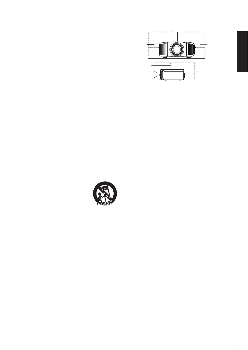
The product should be placed more than one foot away
from heat sources such as radiators, heat registers, stoves,
and other products (including amplifiers) that produce heat.
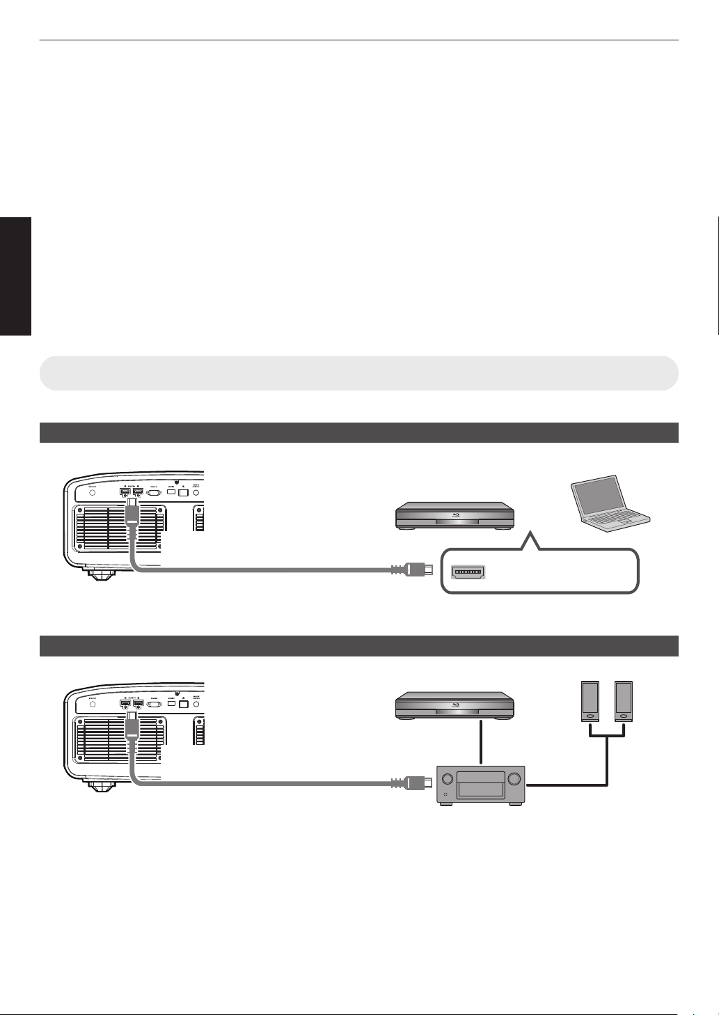
When connecting other products such as VCR’s, and DVD
players, you should turn off the power of this product for
protection against electric shock.
Do not place combustibles behind the cooling fan. For
example, cloth, paper, matches, aerosol cans or gas
lighters that present special hazards when over heated.
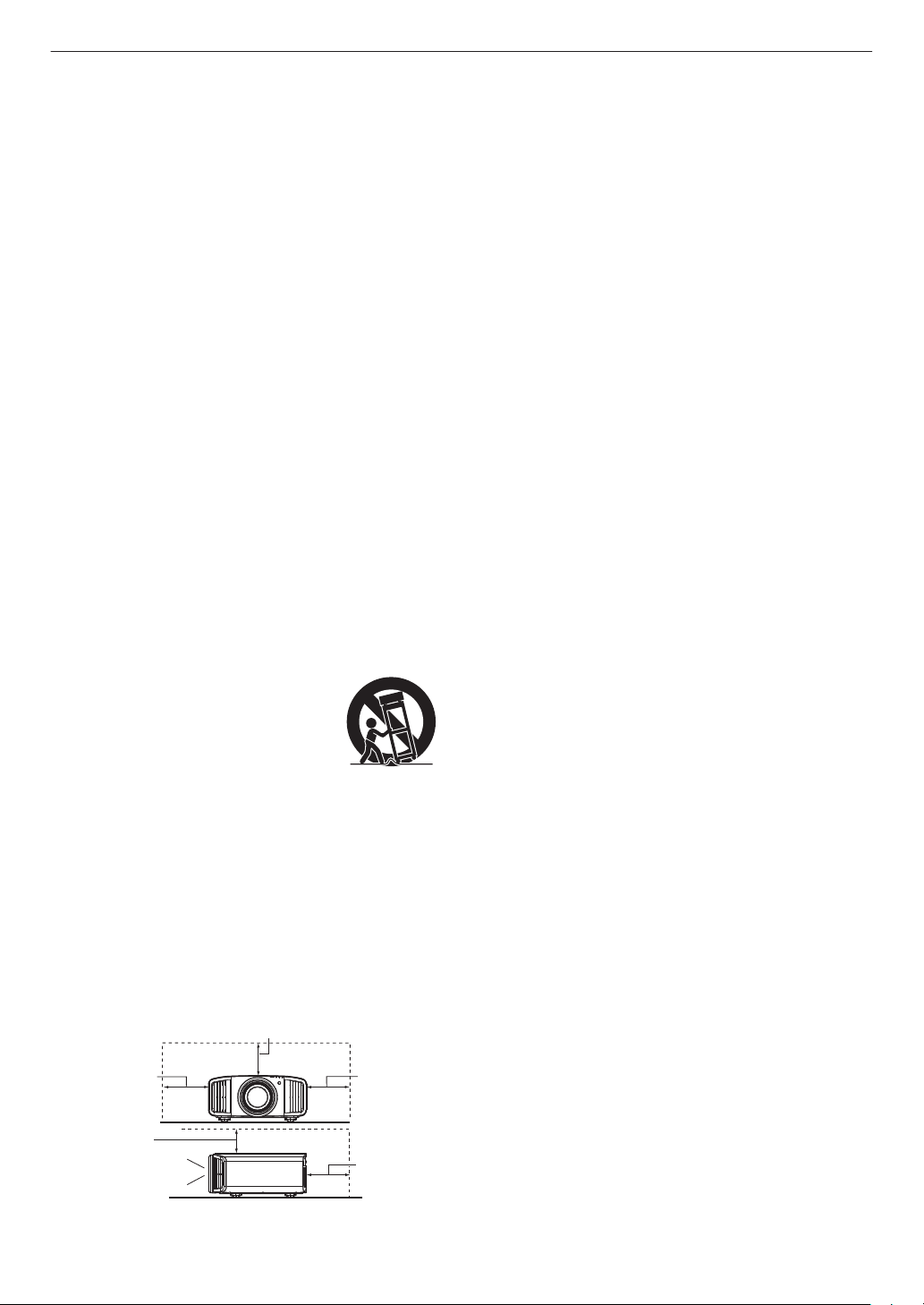
Do not ceiling-mount the projector to a place which tends to
vibrate; otherwise, the attaching fixture of the projector
could be broken by the vibration, possibly causing it to fall
or overturn, which could lead to personal injury.
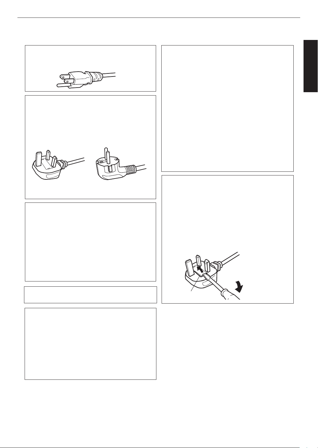
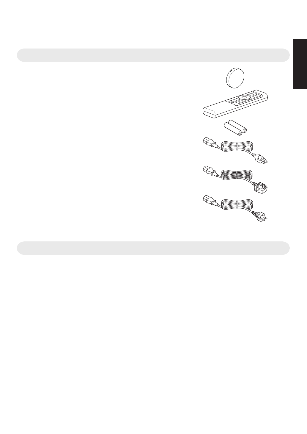
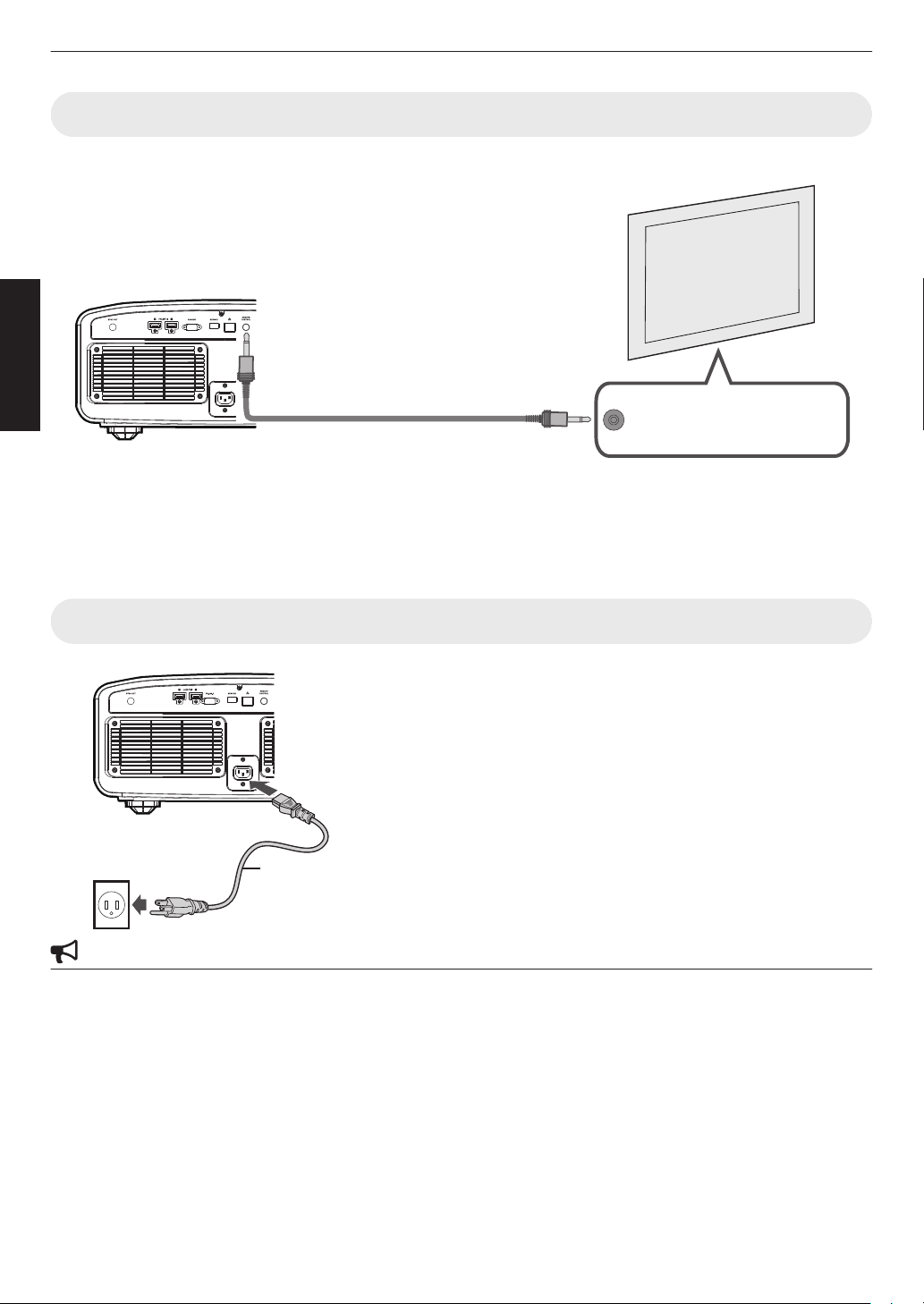
Use only the accessory cord designed for this product to
prevent shock.
For health reasons, please take a break of about 5-15
minutes every 30-60 minutes and let your eyes rest. When
using the devices with 3D function, please refrain from
watching any 3D-images when you feel tired, unwell or if
you feel any other discomfort. Moreover, in case you see a
double image, please adjust the equipment and software
for proper display. Please stop using the unit if the double
image is still visible after adjustment.
Once every three years, please perform an internal test.
This unit is provided with replacement parts needed to
maintain its function (such as cooling fans). Estimated
replacement time of parts can vary greatly depending on
frequency of use and the respective environment. For
replacement, please consult your dealer, or the nearest
authorized JVC service center.
When fixing the unit to the ceiling, Please note that we do
not take any responsibility, even during the warranty period,
if the product is damaged due to use of metal fixtures used
for fixation to the ceiling other than our own or if the
installation environment of said metal fixtures is not
appropriate. If the unit is suspended from the ceiling during
use, please be careful in regard to the ambient temperature
of the unit. If you use a central heating, the temperature
close to the ceiling will be higher than normally expected.
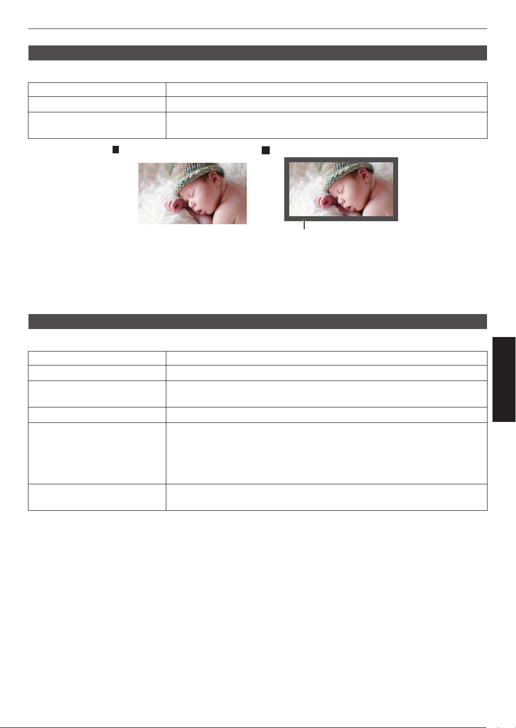
Video images can burn into the electronic component parts.
Please do not display screens with still images of high
brightness or high contrast, such as found in video games
and computer programs. Over a long period of time it might
stick to the picture element. There is no problem with the
playback of moving images, e.g. normal video footage.
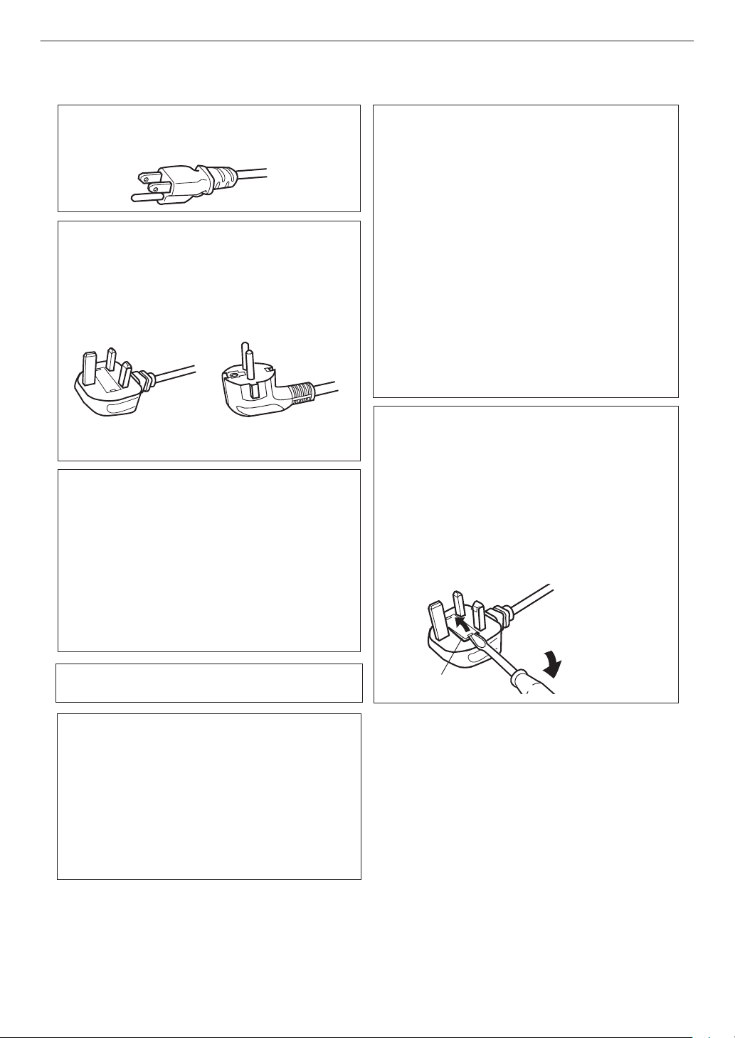
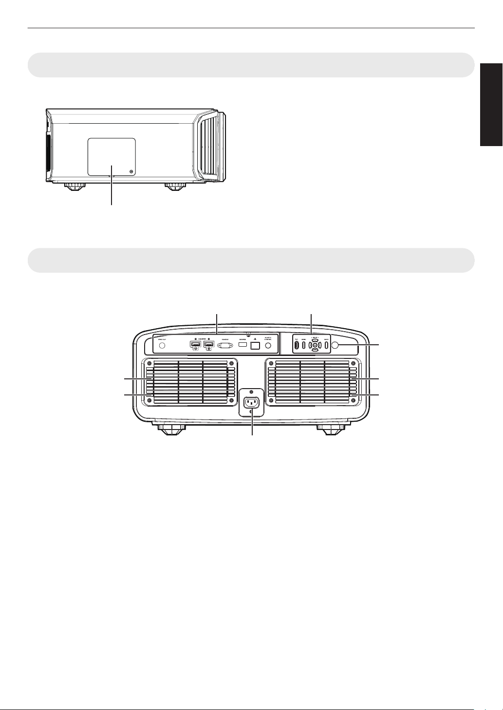
Install the outlet at an accessible height to unplug from the
wall. Or install the circuit breaker at an accessible height to
shut down the projector. If you need information, please
consult your authorized dealer or specialist.
This unit is heavy in weight. Please ensure that there are at
least two persons carrying it.
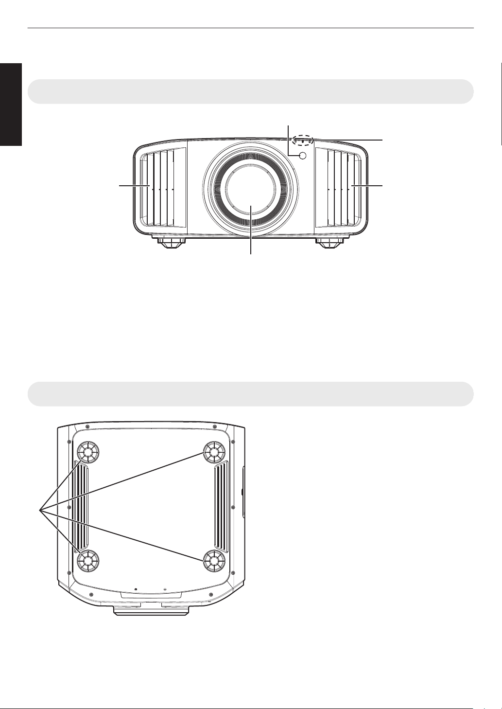
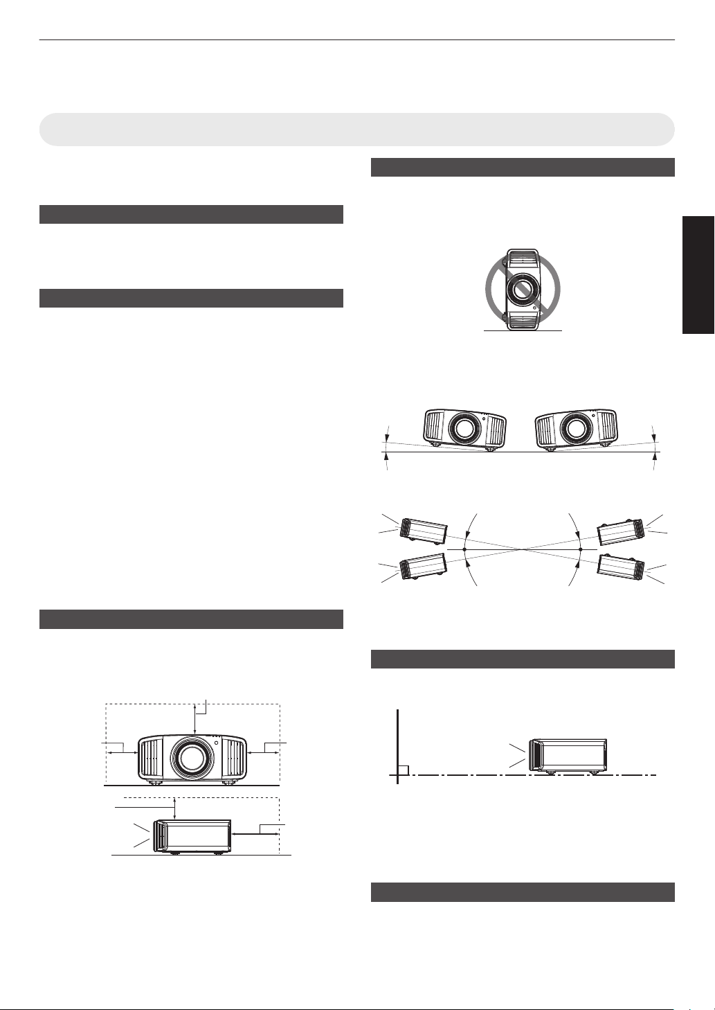
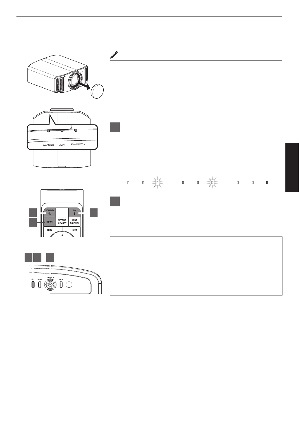
Do not project images with the lens cover attached.
Otherwise, the lens cover may be deformed due to the
heat, or the projector may malfunction.
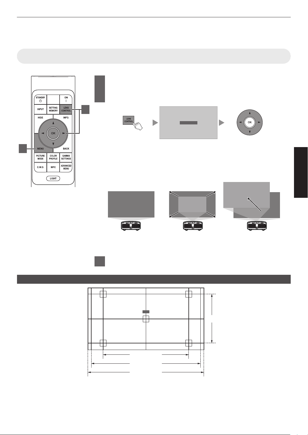
Do not place your hand into the opening near the lens while
lens shift is in progress. Otherwise, your hand may get
caught, resulting in an injury.
-
-
-
-
-
-
Not using the unit for a long time can lead to malfunction.
Please power it on and let it run occasionally. Please avoid
using the unit in a room where cigarettes are smoked. It is
impossible to clean optical component parts if they are
contaminated by nicotine or tar. This might lead to
performance degradation.
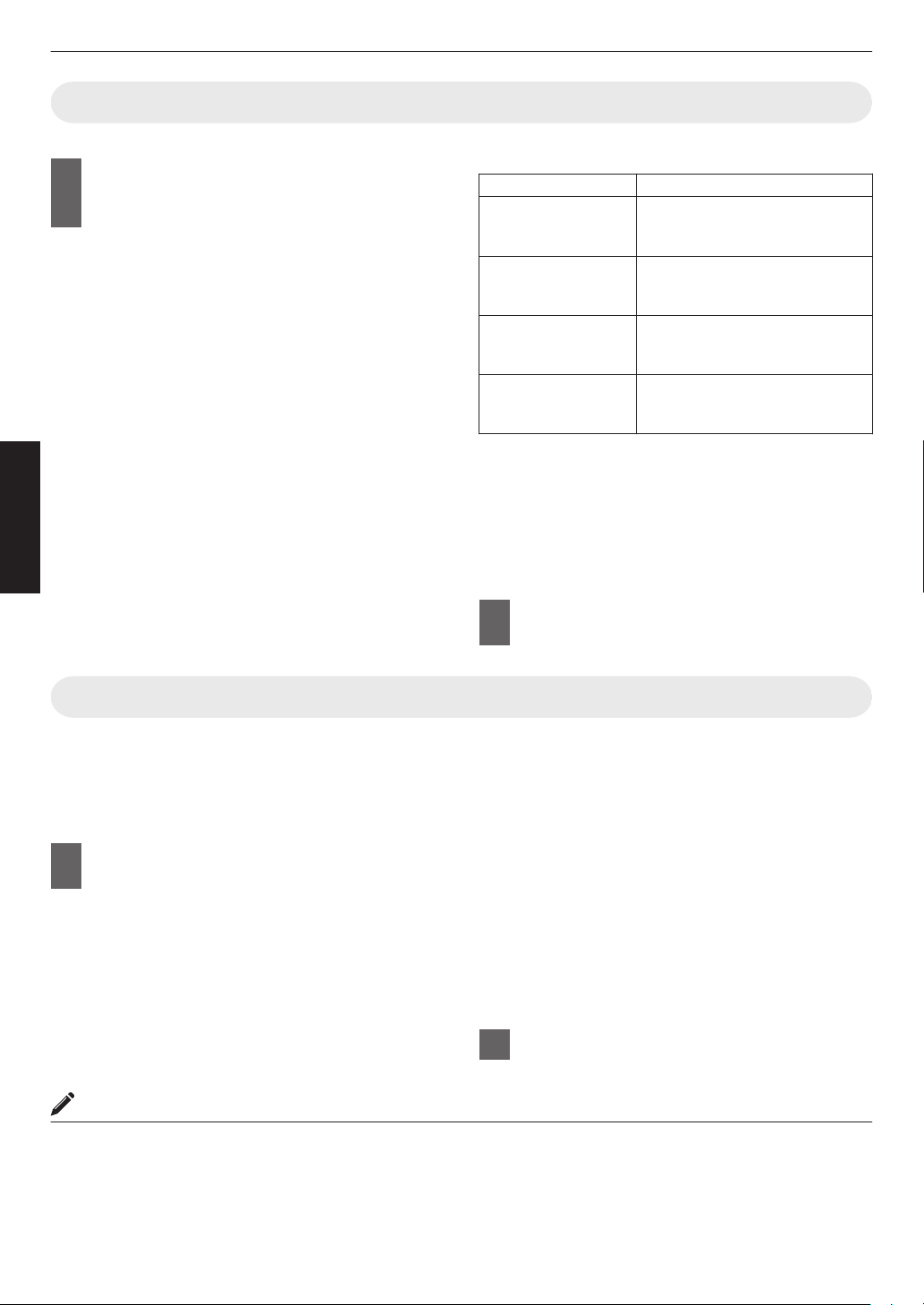
Please watch from a distance three times the height of the
projected image size. Persons with photosensitivity, any
kind of heart disease, or weak health should not use 3D
glasses.
Watching 3D-images might be cause of illness. If you feel
any change in your physical condition, please stop
watching immediately and consult a physician if necessary.
When watching 3D images, it is recommended to take
regular breaks. As the length and frequency of the required
breaks differ for every person, please judge according to
your own condition.
If your child watches while wearing 3D glasses, it should be
accompanied by its parents or an adult guardian. The adult
guardian should be careful to avoid situations where the
child’s eyes might become tired, as responses to tiredness
and discomfort, etc., are hard to detect, and it is possible
for the physical condition to deteriorate very quickly. As the
visual sense is not yet fully developed in children under the
age of 6, please consult a physician in regard to any
problem concerning 3D-images if necessary.
Note that when using the 3D feature, the video output may
appear different from the original video image due to image
conversion on the device.
* DO NOT allow any unqualified person to
install the unit.
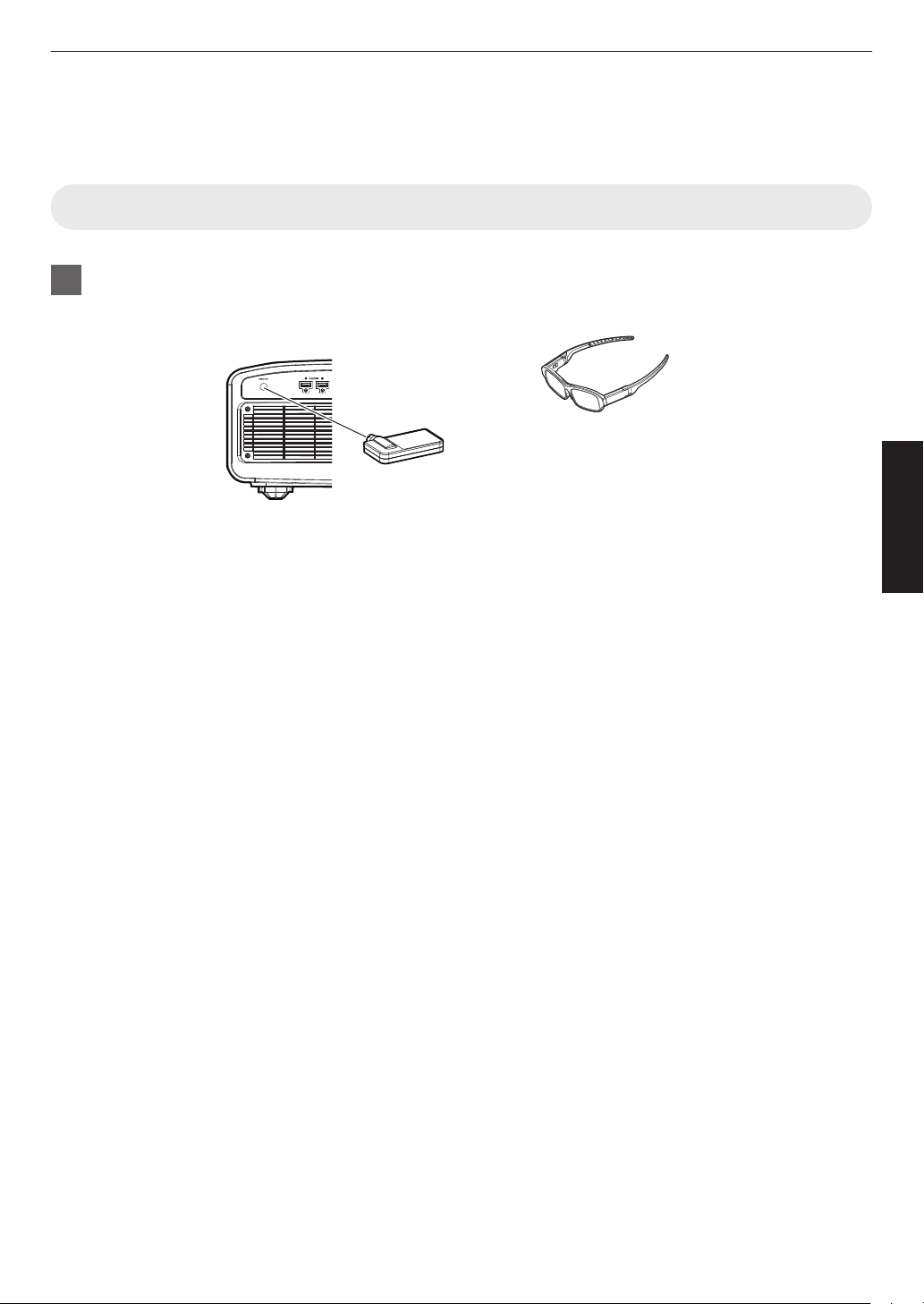
Pay attention to the following when using the devices
with 3D function.
Be sure to ask your dealer to install the unit
(e.g.attaching it to the ceiling) since special
technical knowledge and skills are required for
installation. If installation is performed by an
unqualified person, it may cause personal injury or
electrical shock.
-
-
-
-
-
-
-
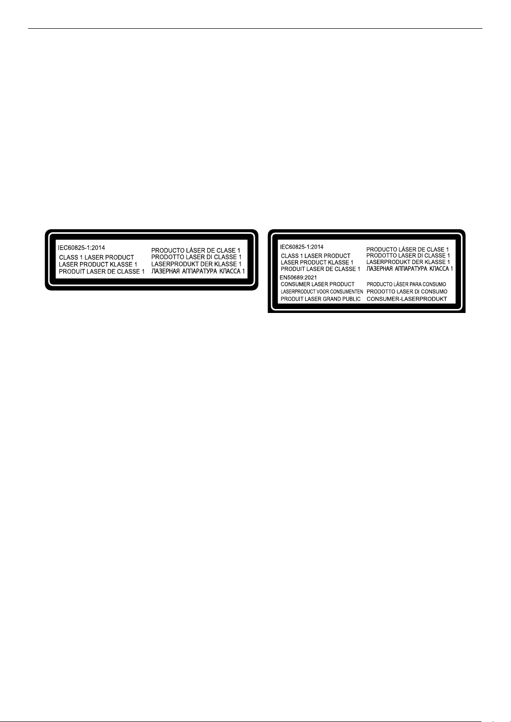
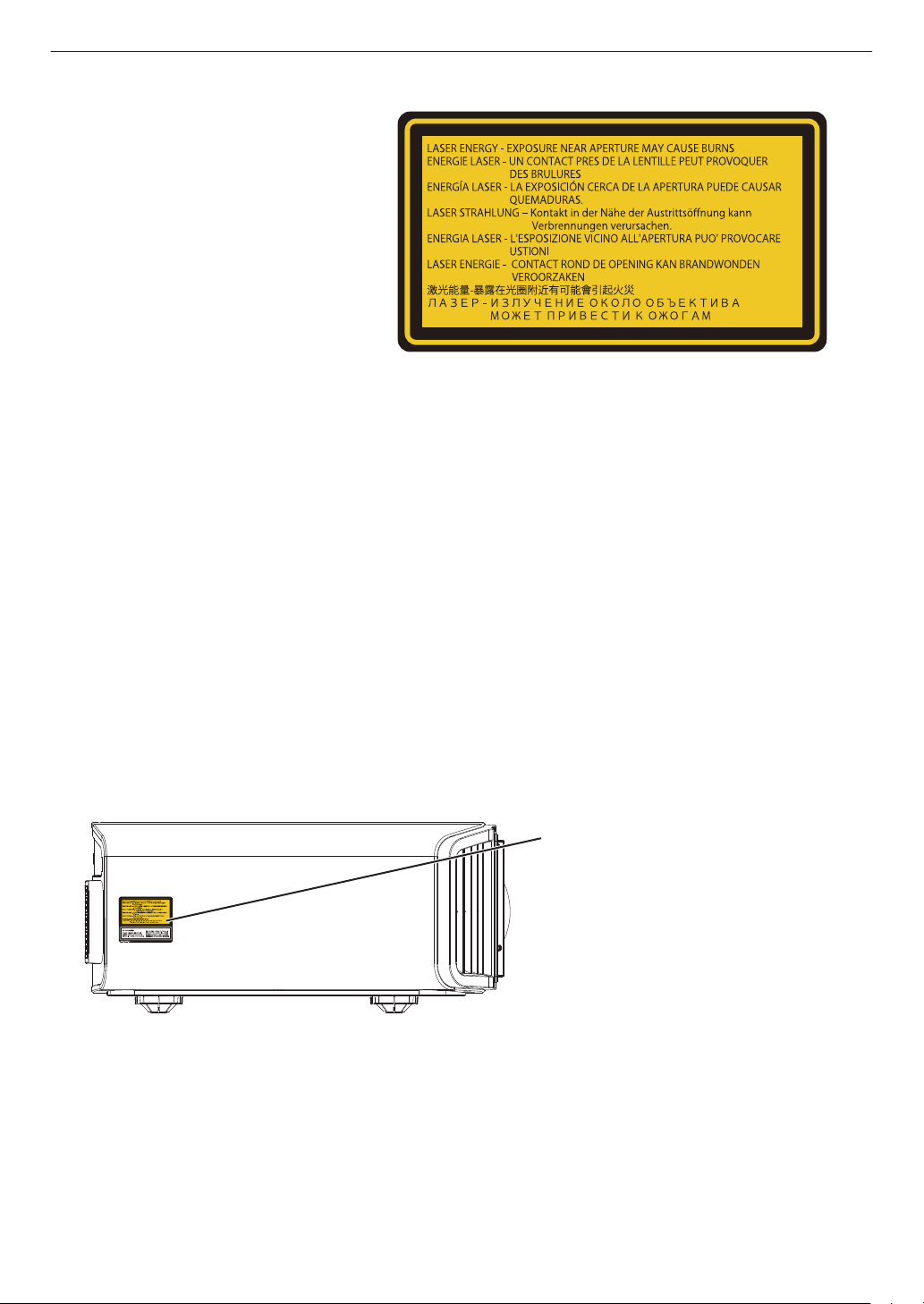
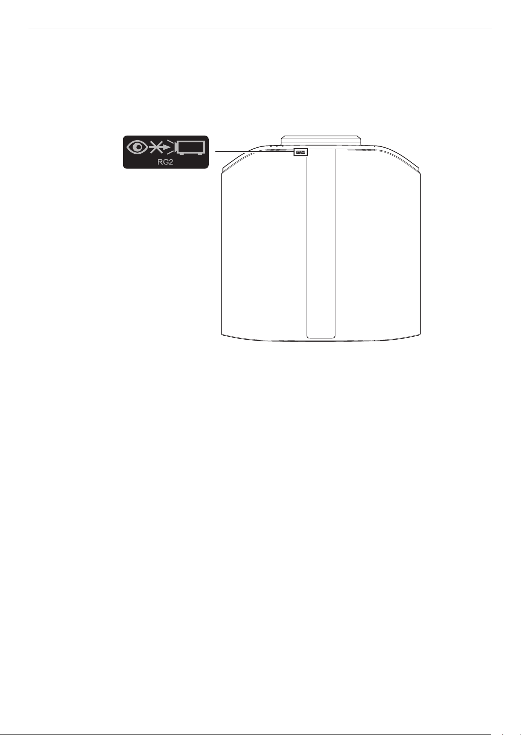
Do not use optical instruments (such as magnifying glass or
reflector) viewing the laser output. It may pose an eye
hazard.
When turning on the projector, ensure that no one is looking
into the projection lens.
Do not look into the lens and openings when the light is on.
Doing so would have serious effects on the human body.
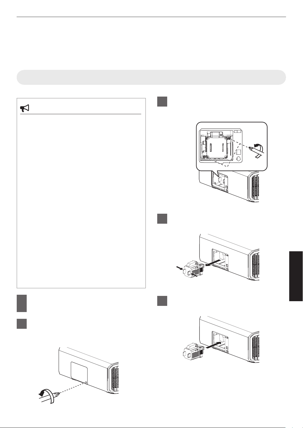
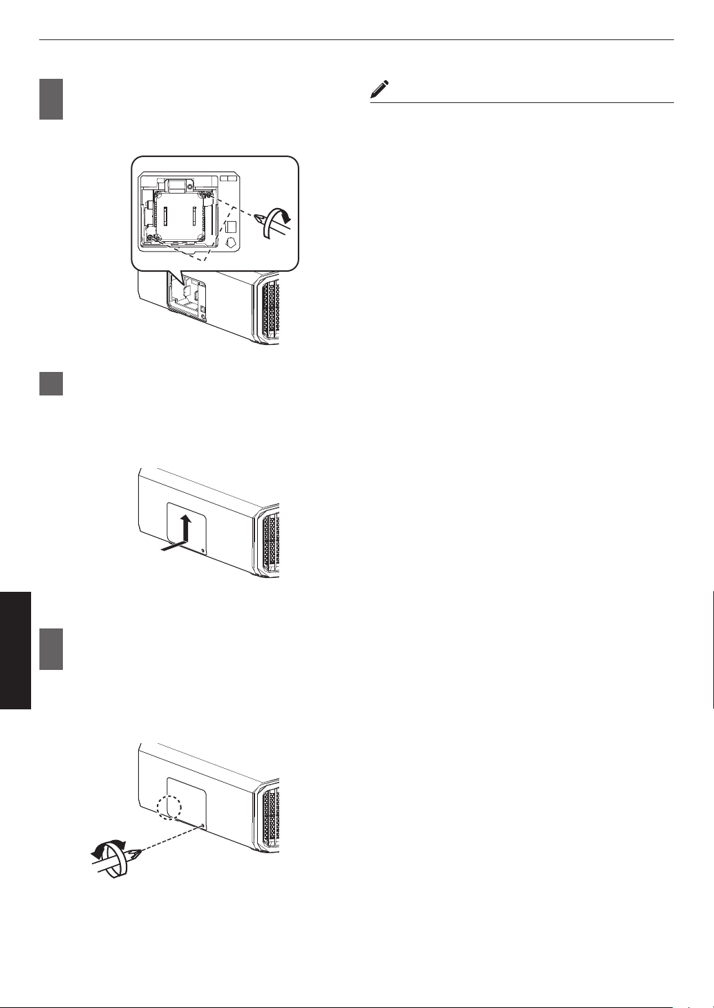
Do not detach or attach the projection lens with the power
connected.
Attempting to disassemble, repair or modify the projector
yourself may lead to serious safety issues.
Using a faulty product not only results in electrical shock or
fire hazard, it can cause visual impairment.
When abnormality occur, stop using the projector
immediately and send it to your authorized dealer for repair.
About the installation place
Do not install the projector in a place that cannot
support its weight securely.
If the installation place is not sturdy enough, the
projector could fall or overturn, possibly causing
personal injury.