810184
63
Zoom out
Zoom in
Previous page
1/72
Next page
OWNER’S GUIDE
AVR580
HIGH-PERFORMANCE
AUDIO/VIDEO
MULTICHANNEL
PROCESSOR/AMPLIFIER
®
AVR580 AUDIO/VIDEO RECEIVER
Typographical Conventions
In order to help you use this manual with the remote control, front-panel controls and
rear-panel connections, certain conventions have been used.
EXAMPLE – (bold type) indicates a specific remote control or front-panel button or
indicator, or rear-panel connection jack
EXAMPLE – (OCR type) indicates a message that is visible on the front-panel
information display
1– (number in a square) indicates a specific front-panel control
a– (number in an oval) indicates a button or indicator on the remote control
¡– (number in a circle) indicates a rear-panel connection
A– (letter in a square) indicates an indicator in the front-panel information display
å
– (letter in an oval) indicates a button on the Zone II remote
Declaration of Conformity
We, Harman Consumer International
2, route de Tours
72500 Château-du-Loir
France
declare in own responsibility that the product described
in this owner’s manual is in compliance with technical
standards:
EN 55013:2001
EN 55020:2002
EN 61000-3-2:2000
EN 61000-3-3:1995+A1:2001
EN 60065:2002
Gary Mardell
Harman Consumer International
Château-du-Loir, France 4/04
4Introduction
5Important Safety Information
5Unpacking
6Front-Panel Controls
8Front-Panel Information Display
9Rear-Panel Connections
12 Main Remote Control Functions
16 Zone II Remote Control Functions
17 Installation and Connections
20 System Configuration
20 Speaker Placement
20 System Setup
22 Input Setup
22 Surround Setup
24 Speaker Setup
26 Delay Settings
27 Output Level Adjustment
27 Using EzSet
28 Manual Output Level Adjustment
30 Operation
30 Basic Operation
30 Source Selection
30 6-Channel/8-Channel Direct Input
30 Volume Control
31 Surround Mode Selection
31 Digital Audio Playback
34 Surround Mode Chart
35 Tuner Operation
35 Tape Recording
36 Output Level Trim Adjustment
37 Advanced Features
37 Surround Amplifier Channel Assignment
37 Display Brightness
37 Turn-On Volume Level
38 Semi-OSD Settings
38 Full-OSD Time-Out Adjustment
39 Multiroom Operation
39 Multiroom Setup
39 Multiroom Operation
41 Programming the Remote
41 Programming the Product Codes
41 Direct Code Entry
41 Auto Search Method
41 Code Readout
42 Learning Codes
42 Macro Programming
43 Programmed Device Functions
44 Volume Punch-Through
44 Channel Control Punch-Through
44 Transport Control Punch-Through
45 Reassigning Device Control
Selectors
45 Resetting the Remote Memory
46 Function List
48 Setup Code Tables
68 Troubleshooting Guide
68 Processor Reset
69 Technical Specifications
See trademark acknowledgements on page 69.
3
1. Read these instructions.
2. Keep these instructions.
3. Heed all warnings.
4. Follow all instructions.
5. Do not use this apparatus near water.
6. Clean only with a dry cloth.
7. Do not block any ventilation
openings. Install in accordance with the
manufacturer’s instructions.
8. Do not install near any heat sources
such as radiators, heat
registers, stoves or other apparatus
(including amplifiers) that produce heat.
9. Do not defeat the safety purpose of
the polarized or grounding-type plug. A
polarized plug has two blades with one
wider than the other. A grounding-type
plug has two blades and a third ground-
ing prong. The wide blade or the third
prong are
provided for your safety. If the
provided plug does not fit into your out-
let, consult an electrician for replace-
ment of the obsolete outlet.
10. Protect the power cord from being
walked on or pinched,
particularly at plugs, convenience recep-
tacles and the point where
they exit from the apparatus.
11. Only use attachments/accessories
specified by the manufacturer.
12. Use only with the cart,
stand, tripod, bracket or table
specified by the manufacturer
or sold with the apparatus.
When a cart is used, use caution
when moving the cart/apparatus combi-
nation to avoid injury from tip-over.
13. Unplug this apparatus during light-
ning storms or when unused for long
periods of time.
14. Refer all servicing to qualified ser-
vice personnel. Servicing is required
when the apparatus has been damaged
in any way, such as power-supply cord
or plug is damaged, liquid has been
spilled or objects have fallen into the
apparatus, the apparatus has been
exposed to rain or moisture, does not
operate normally, or has been dropped.
15. Do not use attachments not recom-
mended by the product manufacturer, as
they may cause hazards.
16. This product should be operated only
from the type of power source indicated
on the marking label. If you are not sure
of the type of power supply to your
home, consult your product dealer or
local power company. For products
intended to operate from battery power,
or other sources, refer to the operating
instructions.
17. If an outside antenna or cable sys-
tem is connected to the product, be sure
the antenna or cable system is grounded
so as to provide some protection against
voltage surges and built-up static
charges. Article 810 of the National
Electrical Code, ANSI/NFPA 70, provides
information with regard to proper
grounding of the mast and supporting
structure, grounding of the lead-in wire
to an antenna discharge unit, size of
grounding conductors, location of antenna-
discharge unit, connection to grounding
electrodes, and requirements for the
grounding electrode. See Figure A.
18. An outside antenna system should
not be located in the vicinity of over-
head power lines or other electric
light or power circuits, or where it
can fall into such power lines or circuits.
When installing an outside antenna
system, extreme care should be taken
to keep from touching such power lines
or circuits, as contact with them might
be fatal.
19. Do not overload wall outlets, exten-
sion cords, or integral convenience
receptacles, as this can result in a risk
of fire or electric shock.
20. Never push objects of any kind into
this product through openings, as they
may touch dangerous voltage points or
short-out parts that could result in a fire
or electric shock. Never spill liquid of
any kind on the product.
21. Do not attempt to service this prod-
uct yourself, as opening or removing
covers may expose you to dangerous
voltage or other hazards. Refer all ser-
vicing to qualified service personnel.
22. When replacement parts are
required, be sure the service technician
has used replacement parts specified by
the manufacturer or that have the same
characteristics as the original part.
Unauthorized substitutions may result in
fire, electric shock or other hazards.
23. Upon completion of any service or
repairs to this product, ask the service
technician to perform safety checks to
determine that the product is in proper
operating condition.
24. The product should be mounted to a
wall or ceiling only as recommended by
the manufacturer.
read first!
Important Safety Precautions!
Antenna Lead-In Wire
Ground Clamp
Antenna Discharge Unit (NEC Section 810-20)
Grounding Conductors (NEC Section 810-21)
Electric Service Equipment
Ground Clamps
Power Service Grounding Electrode System
(NEC Art. 250, Part H)
Figure A.
Example of Antenna Grounding as per
National ElectricalCode ANSI/NFPA 70
HCGUL1492/6500 02/2003
The exclamation point within an equilateral
triangle is intended to alert the user to the
presence of important operating and
maintenance (servicing) instructions in the
literature accompanying the appliance.
CAUTION
RISK OF ELECTRIC SHOCK
DO NOT OPEN
CAUTION: To reduce the risk of electric shock,
do not remove cover (or back).
No user-serviceable parts inside.
Refer servicing to qualified service personnel.
CAUTION: To prevent electric shock,
do not use this (polarized) plug with
an extension cord, receptacle or other outlet
unless the blades can be fully inserted to
prevent blade exposure.
The lightning flash with arrowhead symbol,
within an equilateral triangle, is intended to
alert the user to the presence of uninsulated
“dangerous voltage” within the product’s
enclosure that may be of sufficient magnitude to constitute
a risk of electric shock to persons.
4
INTRODUCTION
Thank you for choosing JBL®!With
the purchase of a JBL
®
AVR580, you are
about to begin many years of listening
enjoyment. Designed to provide all the
excitement and detail of movie sound-
tracks and
every nuance of musical selec-
tions, the AVR580
is truly a multichannel
receiver for the new millennium.
The AVR580 has been engineered so that
it is easy to take advantage of all the
power of its digital technology. However,
to obtain the maximum enjoyment from
your new receiver, we urge you to read
this manual. A few minutes spent learn-
ing the functions of the various controls
will enable you to take advantage of all
the power the AVR580 is able to deliver.
If you have any questions about this prod-
uct, its installation or its operation,
please contact your retailer or custom
installer. They are your best local sources
of information.
Description and Features
The AVR580 is among the most versatile
and multifeatured A/V receivers avail-
able, incorporating a wide range of lis-
tening options. In addition to Dolby*
Digital and DTS®decoding for digital
sources, a broad choice of Matrix sur-
round-encoded or Stereo surround modes
are available for use with sources such
as CD, VCR, TV broadcasts and the
AVR580’s own FM/AM tuner. Along with
Dolby Digital EX, Dolby Pro Logic*II,
DTS Neo:6®, Dolby 3 Stereo, and Hall
and Theater modes, the AVR580 offers
Harman
International’s exclusive Logic 7®
processing in both 5.1 and 7.1 versions to
create a wider, more enveloping
field envi-
ronment and more defined fly-overs and
pans. Another exclusive is VMAx®, which
uses proprietary processing to create an
open, spacious sound field even when
only two front speakers are available.
Finally, the AVR580 offers decoding of
MP3 data, so that you may listen to the
latest music selections directly from com-
patible computers or playback devices
with the power and fidelity you expect
from JBL.
In addition to providing a wide range of
listening options, the AVR580 is easy to
configure so that it provides the best
results with your speakers and specific
listening-room environment. On-screen
menus make it simple to enter settings
for speaker configurations and bass man-
agement, and the EzSet remote measures
a systems sound levels and automatically
calibrates them for perfectly balanced
sound field presentation.
For the ultimate in flexibility, the AVR580
features connections for five video
devices, all with both composite and S-
Video inputs. Two additional audio inputs
are available, and six digital inputs make
the AVR580 capable of handling all the
latest digital audio sources. For compati-
bility with the latest HDTV video sources
and progressive scan DVD players, the
AVR580 also features two-input, wide-
bandwidth, low-crosstalk component
video switching.
The front panel offers coaxial and optical
digital inputs for direct connection to dig-
ital recorders. Two video recording out-
puts, preamp-out and a color-coded eight-
channel input, with complete digital bass
management, make the AVR580 virtually
future-proof, with everything needed to
accommodate tomorrow’s new formats
right onboard.
The AVR580’s flexibility and power
extend beyond your main home theater or
listening room. The AVR580 includes a
sophisticated multizone control system
that allows you to select one source for
use in the main room and a different
source for audio and video distribution to
a second zone. Complete volume control
in the second zone is possible with a
separate infrared control link. To make
it easy to operate the AVR580 from a
remote zone, a separate “Zone II” remote
is included. Additionally, the AVR580
includes the option to assign two of its
output channels to the multiroom system.
The AVR580’s powerful amplifier uses
traditional JBL high-current design tech-
nologies to meet the wide dynamic range
of any program selection.
With
state-of-the-art circuitry and time-
honored circuit designs, the AVR580 is the
perfect combina
tion of the latest in digital
audio technology, a
quiet yet powerful
analog amplifier in an
elegant, easy-to-
use package.
A wide range of digital and matrix
surround
modes, including Dolby
®
Digital, Dolby Digital EX
, Dolby
Pro Logic®II, DTS®
, DTS-ES®
Discrete and Matrix, and
DTS Neo:6®
Seven channels of high-current
amplification with two channels
assignable to either surround back
or multiroom applications
Logic 7
®
processing
, available with
both 7.1 and 5.1 configurations in a
variety of modes, and two modes
of VMAx®
MP3 decoding for use with com-
puters and digital audio players
remote automatically
sets
output levels for optimum
performance
High-bandwidth, HDTV-compatible
component video switching
Front-panel analog A/V inputs
Multiple digital inputs and outputs
Discrete front-panel coaxial and
optical digital inputs for easy
connection to portable digital
devices and the latest video game
consoles
Extensive bass management
options, including three separate
crossover groupings
On-screen menu and display
system
Extensive multiroom options,
including a standard Zone II
remote and assignable amplifier
channels for listening to a separate
source in a remote zone
TM
5
SAFETY INFORMATION
Important Safety Information
Verify Line Voltage Before Use
Your AVR580 has been designed for use
with 220–240-volt AC current. Connection
to a line voltage other than that for which
it is intended can create a safety and fire
hazard and may damage the unit.
Depending on the electrical requirements
in your area or the wiring in your home,
the power cords included with your AVR
may not be the correct ones, and you may
need to contact your local JBL distributor
to obtain the correct power cord.
If you have any questions about the volt-
age requirements for your specific model,
or about the line voltage in your area, con-
tact your selling dealer before plugging the
unit into a wall outlet.
Do Not Use Extension Cords
To avoid safety hazards, use only the
power cord attached to your unit. We do
not recommend that extension cords be
used with this product. As with all elec-
trical devices, do not run power cords
under rugs or carpets or place heavy
objects on them. Damaged power cords
should be replaced immediately by an
authorized service center with a cord
meeting factory specifications.
Handle the AC Power Cord Gently
When disconnecting the power cord from
an AC outlet, always pull the plug; never
pull the cord. If you do not intend to use
the unit for any considerable length of
time, disconnect the plug from the AC
outlet.
Do Not Open the Cabinet
There are no user-serviceable compo-
nents inside this product. Opening the
cabinet may present a shock hazard, and
any modification to the product will void
your guarantee. If water or any metal
object such as a paper clip, wire or a
staple accidentally falls inside the unit,
disconnect it from the AC power source
immediately, and consult an authorized
service center.
Installation Location
To ensure proper operation and to
avoid the potential for safety hazards,
place the unit on a firm and level sur-
face. When placing the unit on a shelf,
be certain that the shelf and any
mounting hardware can support the
weight of the product.
Make certain that proper space is pro-
vided both above and below the unit
for ventilation. If this product will be
installed in a cabinet or other enclosed
area, make certain that there is suffi-
cient air movement within the cabinet.
Under some circumstances a fan may
be required.
Do not place the unit directly on a
carpeted surface.
Avoid installation in extremely hot or
cold locations, or in an area that is
exposed to direct sunlight or heating
equipment.
Avoid moist or humid locations.
Do not obstruct the ventilation slots
on the top of the unit, or place
objects directly over them.
Due to the weight of the AVR580 and
the heat generated by the amplifiers,
there is the remote possibility that
the rubber padding on the bottom of
the unit’s feet may leave marks on
certain wood or veneer materials. Use
caution when placing the unit on soft
woods or other materials that may be
damaged by heat or heavy objects.
Cleaning
When the unit gets dirty, wipe it with a
clean, soft, dry cloth. If necessary, wipe
it with a soft cloth dampened with mild
soapy water, then a fresh cloth with clean
water. Wipe dry immediately with a dry
cloth. NEVER use benzene, aerosol
cleaners, thinner, alcohol or any other
volatile cleaning agent. Do not use
abrasive cleaners, as they may damage
the finish of metal parts. Avoid spraying
insecticide near the unit.
Moving the Unit
Before moving the unit, be certain to
disconnect any interconnection cords
with other components, and make certain
that you disconnect the unit from the
AC outlet.
Unpacking
The carton and shipping materials used
to protect your new receiver during ship-
ment were specially designed to cushion
it from shock and vibration. We suggest
that you save the carton and packing
materials for use in shipping if you move,
or should the unit ever need repair.
To minimize the size of the carton in stor-
age, you may wish to flatten it. This is
done by carefully slitting the tape seams
on the bottom and collapsing the carton.
Other cardboard inserts may be stored in
the same manner. Packing materials that
cannot be collapsed should be saved
along with the carton in a plastic bag.
If you do not wish to save the packaging
materials, please note that the carton
and other sections of the shipping protec-
tion are recyclable. Please respect the
environment and discard those materials
at a local recycling center.
At this time you should remove the pro-
tective plastic film from the front-panel
lens. Leaving the film in place will affect
the performance of your remote control.
6
1Main Power Switch: Press this
button to apply power to the AVR580.
When the switch is pressed in, the unit
is placed in a Standby mode, as indicated
by the red Power Indicator 3in the
center of the System Power Control
2. This button MUST be pressed in to
operate the unit. To turn the unit off and
prevent the use of the remote control,
this switch should be pressed until it
pops out from the front panel so that the
word “OFF” may be read at the top of
the switch.
NOTE: This switch is normally left in the
“ON” position.
2System Power Control: When the
Main Power Switch 1is “ON,” press
this button to turn on the AVR580; press
it again to turn the unit off. Note that
the Power Indicator 3in the center
of the switch will turn orange when the
unit is on.
3Power Indicator: This LED will be lit
in red when the unit is in the Standby
mode to signal that the unit is ready to be
turned on. When the unit is in operation,
the indicator will turn orange.
4Headphone Jack: This jack may be
used to listen to the AVR580’s output
through a pair of headphones. Be certain
that the headphones have a standard
6.4mm (1/4") stereo phone plug. The main
room speakers will automatically be turned
off when the headphone jack is in use.
5Tone Mode: This button controls the
tone control settings, enabling adjustment
of the bass and treble boost/cut and bal-
ance or the removal of the tone controls
from the signal path. The first press of the
button displays a TONE IN message in
the Main Information Display ˜.
If
you wish to set the tone controls to “flat,
without any treble, bass or balance alter-
ation, press the or
Selector Buttons
)# so that TONE OUT appears in
the Lower Display Line B.
6Speaker Selector: Press this button
to begin the process of configuring the
AVR580 for the type of speakers it is
being used with. For information on
configuring the speaker settings, see
page 24.
7Surround Mode Group Selector:
Press this button to select the top-level
group of surround modes. Each press of
the button will select a major mode
grouping in the following order:
Once the button is pressed so that the
name of the desired surround mode group
appears in the on-screen display and in
the Lower Display Line B, press the
Surround Mode Selector 8to cycle
through the individual modes available.
For example, press this button to select
Dolby modes, and then press the
Surround Mode Selector 8to choose
from the various mode options.
8Surround Mode Selector: Press this
button to select from among the available
surround mode options for the major
mode group selected. The specific modes
will vary based on the number of speak-
ers available, the major mode group and
whether the input source is digital or ana-
log. For example, press the Surround
Mode Group Selector 7to select a
major mode grouping such as Dolby or
Dolby Modes _ DTS Digital Modes _ VMAx Modes
_ DSP Modes _ Stereo Modes _ Logic 7 Modes
FRONT-PANEL CONTROL
1Main Power Switch
2System Power Control
3Power Indicator
4Headphone Jack
5Tone Mode
6Speaker Selector
7Surround Mode Group Selector
8Surround Mode Selector
9Tuning Selector
)Button
!Tuner Band Selector
@Set Button
#Button
$Preset Station Selector
%Input Source Selector
^Tuner Mode Selector
&Optical 3 Digital Input
*Coaxial 3 Digital Input
(Video 4 Video Input Jacks
ÓVideo 4 Audio Input Jacks
ÔBass Control
Balance Control
ÒTreble Control
ÚChannel Adjust Selector
ÛDelay Adjust Selector
ÙDigital Input Selector
ıVolume Control
ˆInput Indicators
˜Main Information Display
¯Remote Sensor Window
˘Surround Mode Indicators
7
Logic 7, and then press this button to see
the specific mode choices that are avail-
able. For more information on mode
selection, see page 31.
9Tuning Selector: Press the left side
of the button to tune lower-frequency sta-
tions and the right side of the button to
tune higher-frequency stations. When a
station with a strong signal is reached,
the TUNED Indicator Iwill be lit in
the Main Information Display ˜.
)‹Button: When making system con-
figuration changes using the front-panel
controls, press this button to scroll left
through the available choices for the
option being adjusted.
!Tuner Band Selector: Pressing this
button will automatically switch the
AVR580 to the Tuner mode. Pressing it
again will switch between the AM and
FM frequency bands. (See page 35 for
more information on the tuner.)
@Set Button: When making system
configuration changes using the front-
panel controls, press this button to enter
a setting into the unit’s memory.
#Button: When making system con-
figuration changes using the front-panel
controls, press this button to scroll right
through the available choices for the
option being adjusted.
$Preset Station Selector: Press this
button to scroll up or down through the
list of stations that have been entered
into the preset memory. (See page 35 for
more information on tuner programming.)
%Input Source Selector: Press this
button to change the input source.
^Tuner Mode Selector: Press this but-
ton to select Auto or Manual tuning. When
the button is pressed so that the AUTO
Indicator Jlights, the tuner will search
for the next station with an acceptable sig-
nal when the Tuning Selector 9u
é
is pressed. When the button is
pressed so that the AUTO Indicator J
is not lit, each press of the Tuning
Selector 9u
é
will increase the fre-
quency. (See page 35 for more information
on using the tuner.) This button may also
be used to switch between Stereo and
Mono modes for FM radio reception.
When weak reception is encountered,
press the button until the STEREO
Indicator Hgoes out to switch to Mono
reception. Press and hold again to switch
back to Stereo mode. (See page 35 for
more information on using the tuner.)
&Optical 3 Digital Input: Connect the
optical digital output of an audio or video
product to this jack.
*Coaxial 3 Digital Input: Connect
the coaxial digital input of a digital audio
product such as a portable audio player
or video game to this jack.
(Video 4 Video Input Jacks: These
jacks may be used to connect the video
play/out jacks of a video game or
portable video product such as a cam-
corder, video game or digital still camera
to your system.
ÓVideo 4 Audio Input Jacks: These
audio/video
jacks may be used for connec-
tion to the audio play/out
jacks of a video
game or portable audio/video product
such as a camcorder or portable audio
player.
ÔBass Control: Use this control to
boost or reduce the low-frequency output
of the left/right front channels by as
much as ±10dB. Set this control as you
find suitable to adjust to your specific
taste or room acoustics.
Balance Control: Use this control to
change the relative volume for the front
left/right channels.
NOTE: When multichannel surround
modes are in use, this control should be
at the midpoint, or “12 o’clock,” position
for proper operation.
ÒTreble Control: Use this control to
boost or reduce the high-frequency output
of the left/right front channels by as
much as ±10dB. Set this control as you
find suitable to adjust to your specific
taste or room acoustics.
ÚChannel Adjust Selector: Press the
button to begin the process of adjusting
the channel level outputs using the
source currently playing through your
AVR. For complete information on adjust-
ing the channel output level, see page 36.
ÛDelay Adjust Selector: Press this
button to begin the process of adjusting
the delay settings for Dolby surround
modes. See page 26 for more information
on delay adjustments.
ÙDigital Input Selector: Press this
button to begin the process of selecting a
digital source for use with the currently
selected input. Once the button has been
pressed, use the or Buttons )#
to choose the desired input and then
press the Set Button @to enter the
setting into the unit’s memory. See page
31 for more information on digital audio.
ıVolume Control: Turn this knob
clockwise to increase the volume, coun-
terclockwise to decrease the volume.
If the AVR580 is muted, adjusting the
volume will automatically release the
unit from the silenced condition.
ˆInput Indicators: The current
input source for the AVR580 will light
in orange.
˜Main Information Display: This
display delivers messages and status
indications to help you operate the
receiver. (See page 8 for a complete
explanation of the Information Display.)
¯Remote Sensor Window: The sen-
sor behind this window receives infrared
signals from the remote control. Aim the
remote at this area and do not block or
cover it unless an external remote sensor
is installed.
˘Surround Mode Indicators: The
surround mode and digital bitstream in
use will light in orange. Note that
depending on the specific combination of
input sources and surround mode select-
ed, more than one indicator may light.
(See page 34 for more information.)
8
FRONT-PANEL INFORMATION DISPLAY
AUpper Display Line
BLower Display Line
COSD Indicator
DMultiroom Indicator
ESpeaker/Channel Input Indicators
FPRESET Indicator
GMEMORY Indicator
HSTEREO Indicator
ITUNED Indicator
JAUTO Indicator
K192kHz Indicator
L96kHz Indicator
AUpper Display Line: Depending on
the unit’s status, a variety of messages will
appear here. In normal operation, the cur-
rent audio and video input source informa-
tion will appear on this line.
BLower Display Line: Depending on
the unit’s status, a variety of messages
will appear here. In normal operation, the
current surround mode name will appear
on this line.
COSD Indicator: When the OSD sys-
tem is in use, this indicator lights to
remind you that the other indicators in
this display do not function when the On-
Screen Display is being used.
DMultiroom Indicator: This indicator
lights when the multiroom system is
active. It will remain lit when the multi-
room system is in use even though the
main room system is in the Standby mode
and all other indicators are dark. (See
page 39 for more information on the
Multiroom system.)
ESpeaker/Channel Input Indicators:
These indicators are multipurpose, indicat-
ing either the speaker type selected for
each channel or the incoming data-signal
configuration. The left, center, right, side
surround and surround back speaker indi-
cators are composed of two boxes, while
the subwoofer is a single box. The center
box lights when a “Small” speaker is
selected, and the
outer boxes light when
“Large” speakers are selected. When none
of the boxes are lit for the center, surround
or subwoofer channels, no speaker has
been selected for one of those positions.
(See page 24 for more information on
speaker setup.) The letters inside each of
the
center boxes display the active input
channels. For standard analog inputs, only
the L and R will light, indicating a stereo
input. When a digital source is playing, the
indicators
will light to display the channels
being received at the digital input. When
the letters flash, the digital input has been
interrupted. (See page 32 for more infor-
mation on the channel indicators.)
FPRESET Indicator: This indicator
lights when the tuner is in use to show
that the present number for the current
station being listened to appears in the
Upper Display Line. (See page 35 for
more information on tuner presets.)
GMEMORY Indicator: This indicator
flashes when entering presets and other
information into the tuner’s memory.
HSTEREO Indicator: This indicator
lights when an FM station is being tuned
in stereo.
I
TUNED Indicator:
This indicator lights
when a station is being received with suf-
ficient signal strength to provide accept-
able listening quality.
JAUTO Indicator: This indicator lights
when the tuner’s Auto mode is in use.
K192kHz Indicator: This indicator
lights when the digital audio input source
has a 192kHz bit rate.
L96kHz Indicator: This indicator
lights when the digital audio input source
has a 96kHz bit rate.
9
REAR-PANEL CONNECTIONS
¡AM Antenna: Connect the AM loop
antenna supplied with the receiver to these
terminals. If an external AM antenna is
used, make connections to the AM and
GND terminals in accordance with the
instructions supplied with the antenna.
FM Antenna: Connect the supplied
indoor (or an optional external) FM antenna
to this terminal.
£Preamp Outputs: Connect these
jacks to an optional, external power
amplifier for applications where higher
power is desired.
¢Subwoofer Output: Connect this
jack to the line-level input of a powered
subwoofer. If an external subwoofer
amplifier is used, connect this jack to the
subwoofer amplifier input.
Surround Speaker Outputs:
Connect these outputs to the matching +
and – terminals on your surround channel
speakers. In conformance with the new
CEA color-code specification, the blue ter-
minal is the positive, or “+,” terminal that
should be connected to the red (+) termi-
nal on the Surround Left speaker with
older color-coding, while the gray termi-
nal should be connected to the red (+) ter-
minal on the Surround Right speaker with
the older color-coding. Connect the black
(–) terminal on the AVR580 to the match-
ing black negative (–) terminals for each
surround speaker. (See page 17 for more
information on speaker polarity.)
§Front Speaker Outputs: Connect
these outputs to the matching + or – ter-
minals on your left and right speakers.
When making speaker connections
always make certain to maintain correct
polarity by connecting the color-coded
(white for front left and red for front right)
¡AM Antenna
FM Antenna
£Preamp Outputs
¢Subwoofer Output
Surround Speaker Outputs
§Front Speaker Outputs
Fan Vents
Center Speaker Outputs
ªSurround Back/Multiroom Speaker
Outputs
AC Power Cord Jack
Region Selector
¤Video Monitor Outputs
DVD Video Inputs
Video 1 Video Inputs
Video 1 Video Outputs
Video 2 Video Inputs
Video 2 Video Outputs
°Video 3 Video Inputs
·Component Video Monitor Outputs
aComponent Video 1 Inputs
bComponent Video 2 Inputs
cRS-232 Port
dMultiroom IR Input
eRemote IR Input
fRemote IR Output
gCoaxial Digital Audio Output
hMultiroom Audio Outputs
iOptical Digital Audio Output
jCD Audio Inputs
kDVD Audio Inputs
Optical Digital Audio Inputs
Tape Inputs
Tape Outputs
Coaxial Digital Audio Inputs
Video 1 Audio Inputs
Video 1 Audio Outputs
Video 2 Audio Inputs
8-Channel Direct Inputs
Video 2 Audio Outputs
Video 3 Audio Inputs
NOTE: To assist in making the correct
connections for multichannel input, out-
put and speaker connections, all connec-
tion jacks and terminals are color-coded
in conformance with the latest CEA stan-
dards as follows:
Front Left: White
Front Right: Red
Center: Green
Surround Left: Blue
Surround Right: Gray
Surround Back Left: Brown
Surround Back Right: Tan
Subwoofer: Purple
Digital Audio: Orange
Composite Video: Yellow
Component Video “Y”: Green
Component Video “Pr”: Red
Component Video “Pb”: Blue
10
(+) terminals on the AVR580 to the red (+)
terminals on the speakers and the black
(–) terminals on the AVR580 to the black
(–) terminals on the speakers. See page
17 for more information on speaker
polarity.
Fan Vents: These ventilation holes
are the output of the AVR580’s airflow
system. To ensure proper operation of the
unit and to avoid possible damage to del-
icate surfaces, make certain that these
holes are not blocked and that there is at
least three inches of open space between
the vent holes and any wooden or fabric
surface. It is normal for the fan to remain
off at most normal volume levels. An
automatic termperature sensor turns the
fan on only when it is needed.
Center Speaker Outputs: Connect
these outputs to the matching + and –
terminals on your center channel speaker.
In conformance with the new CEA color-
code specification, the green terminal is
the positive, or “+, terminal that should
be connected to the red (+) terminal on
speakers with the older color-coding.
Connect the black (–) terminal on the AVR
to the black (–) terminal on your speaker.
(See page 17 for more information on
speaker polarity.)
ªSurround Back/Multiroom
Speaker Outputs: These speaker termi-
nals are normally used to power the sur-
round back left/surround back right
speakers in a 7.1 channel system. How-
ever, they may also be used to power the
speakers in a second zone, which
will
receive the output selected for a multi-
room system.
To change the output fed to
these terminals from the default of the
Surround Back speakers to the Multiroom
Output, you must change a setting in the
Advanced Menu of the OSD system. See
page 37 for more information on configur-
ing this speaker output. In normal sur-
round system use, the brown and black
terminals are the surround back left chan-
nel positive (+) and negative (–) connec-
tions and the tan and black terminals are
the surround back right positive (+) and
negative (–) terminals. For multiroom use,
connect the brown and black SBL termi-
nals to the red and black connections on
the left remote zone speaker and connect
the tan and black SBR terminals to the
red and black terminals on the right
remote zone speaker.
AC Power Cord Jack: Connect the
AC power cord to this jack when the
installation is complete. To ensure safe
operation, use only the power cord sup-
plied with the unit. If a replacement is
required it must be of the same type and
capacity.
Depending on the electrical requirements
in your area or the wiring in your home,
the power cords included with your AVR
may not be the correct ones, and you may
need to contact your local JBL distributor
to obtain the correct power cord.
Region Selector: Select the position
corresponding to the country in which the
AVR will be used (C, S or K) so that the
video standard and the FM tuner’s fre-
quency increments will be correct. See
page 35 for more information on setting
the Region Selector .
IMPORTANT NOTE: Any adjustments
made to the Region Selector will
not take effect unless the unit is first
fully turned off by pressing the Main
Power Switch 1until it pops out and
the word “OFF” appears on the top of
the button.
¤Video Monitor Outputs: Connect
these jacks to the composite or S-Video
input of a TV monitor or video projector to
view the on-screen menus and the output
of any standard video source selected by
the receiver’s video switcher.
DVD Video Inputs: Connect the com-
posite or S-Video outputs of a DVD player
or other video source to these jacks.
Video 1 Video Inputs: Connect the
composite or S-Video PLAY/OUT jacks of
a VCR or other video source to these
jacks.
Video 1 Video Outputs: Connect the
composite or S-Video REC/IN jacks of a
VCR or other video recording device such
as a DVD recorder or PVR to these jacks.
Video 2 Video Inputs: Connect the
composite or S-Video PLAY/OUT jacks of
a VCR or other video source to these
jacks.
Video 2 Video Outputs: Connect the
composite or S-Video REC/IN jacks of a
VCR or other video recording device such
as a DVD recorder or PVR to these jacks.
°Video 3 Video Inputs: Connect the
composite or S-Video PLAY/OUT jacks of
a VCR or other video source to these
jacks.
·Component Video Monitor
Outputs: Connect these outputs to the
component video inputs of a video projec-
tor or monitor. When a source connected
to one of the Component Video Inputs
ab is selected, the signal will be sent
to these jacks.
aComponent Video 1 Inputs: Connect
the Y/Pr/Pb component video outputs of
a DVD player, HDTV set-top converter,
satellite receiver or other video source
device with component video outputs to
these jacks.
bComponent Video 2 Inputs: Connect
the Y/Pr/Pb component video outputs of
an HDTV set-top converter, satellite
receiver or other video source device with
component video outputs to these jacks.
cRS-232 Port: This jack is used to
enable the AVR580 to be controlled by
an external computer or programmable
remote system that uses RS-232 com-
mands. Due to the complexity of RS-232
connections, we recommend that they be
made by a trained and qualified custom
installer. See page 18 for more informa-
tion on the RS-232 control port.
dMultiroom IR Input: Connect the out-
put of an IR sensor in a remote room to
this jack to operate the AVR580’s multi-
room control system.
eRemote IR Input: If the AVR580’s
front-panel IR sensor is blocked due to
cabinet doors or other obstructions, an
external IR sensor may be used. Connect
the output of the sensor to this jack.
fRemote IR Output: This connection
permits the IR sensor in the receiver to
serve other remote controlled devices.
Connect this jack to the “IR IN” jack on
JBL (or other compatible) equipment.
gCoaxial Digital Audio Output:
Connect this jack to the coaxial digital
input of a CD-R/RW, MiniDisc or other
digital recorder.
hMultiroom Audio Outputs: Connect
these jacks to the optional external audio
power amplifier and video distribution
system that delivers the source selected
for multizone distribution.
iOptical Digital Audio Output:
Connect this jack to the optical digital
input connector on a CD-R/RW, MiniDisc
or other digital recorder.
11
CD Audio Inputs: Connect these
jacks to the analog audio output of a
compact disc player or CD changer.
kDVD Audio Inputs: Connect the
left/right analog outputs of a DVD player
or other audio source to these jacks.
Optical Digital Audio Inputs:
Connect the optical digital output from a
DVD player, HDTV receiver, the S/P-DIF
output of a compatible computer sound
card playing MP3 files or streams, LD
player or CD
player to these jacks. The
signal may be a Dolby Digital signal, a
DTS signal or a standard PCM digital
source.
Tape Inputs: Connect these jacks to
the PLAY/OUT
jacks of an audio recorder.
Tape Outputs: Connect these jacks to
the RECORD/INPUT jacks of an audio
recorder.
Coaxial Digital Audio Inputs:
Connect the coax digital output from a
DVD player, HDTV receiver, the S/P-DIF
output of a compatible computer
sound
card playing MP3 files or streams, LD player
or CD player to these jacks. The signal may
be a Dolby Digital signal, DTS signal or a
standard PCM digital source. Do not con-
nect the RF digital output of an LD player
to these jacks.
Video 1 Audio Inputs: Connect the
left/right PLAY/OUT audio output jacks on
a VCR or other video source to these
jacks.
Video 1 Audio Outputs: Connect the
left/right REC/IN audio input jacks on a
VCR or other video source to these jacks.
Video 2 Audio Inputs: Connect the
left/right PLAY/OUT audio output jacks on
a VCR or other video source to these
jacks.
8-Channel Direct Inputs: These
jacks are used for connection to source
devices such as DVD-Audio or SACD
players with discrete analog outputs.
Depending on the source device in use, all
eight jacks may be used, though in many
cases only connections to the front
left/right, center, surround left/right and
LFE (subwoofer input) jacks will be used
for standard 5.1 audio signals.
Video 2 Audio Outputs: Connect the
left/right REC/IN audio input jacks on a
VCR or other video source to these jacks.
Video 3 Audio Inputs: Connect the
left/right PLAY/OUT audio output jacks
on a VCR, PVR, cable set-top, satellite
receiver, HDTV receiver or other video
source to these jacks.
12
MAIN REMOTE CONTROL FUNCTIONS
aPower Off Button
bIR Transmitter Window
cProgram/SPL Indicator
dPower On Button
eInput Selectors
fAVR Selector
gAM/FM Tuner Select
h6-Channel/8-Channel Direct Input
iTest Button
jSleep Button
kSurround Mode Selector
lNight Mode
mChannel Select Button
n
/
¤
Buttons
o
Button
pSet Button
qDigital Select
rNumeric Keys
sTuner Mode
tDirect Button
uTuning Up/Down
vOSD Button
wDolby Mode Selector
xDTS Digital Mode Selector
yLogic 7 Mode Select Button
zSkip Down Button
`Transport Controls
Skip Up Button
Stereo Mode Select Button
DTS Neo:6 Mode Select
Macro Buttons
Disc Skip Button
Preset Up/Down
Clear Button
Memory Button
Delay/Prev. Ch.
Button
Speaker Select
Multiroom
Volume Up/Down
SPL Selector
Learn Button
Mute
EzSet Sensor Microphone
NOTE: The function names shown here
are each button’s feature when used with
the AVR580. Most buttons have additional
functions when used with other devices.
See pages 46–47 for a list of these
functions.
13
IMPORTANT NOTE: The AVR580’s
remote may be programmed to control up
to eight devices, including
the AVR580.
Before using the remote, it is important to
remember to press the Input Selector
Button ethat corresponds to the unit
you wish to operate. In addition, the
AVR580’s remote is shipped from the fac-
tory to operate the AVR580 and JBL DVD
players. The remote is also capable of
operating a wide variety of other products
using the control codes that are part of
the remote. Before using the remote with
other products, follow the instructions on
pages 40–41 to program the proper codes
for the products in your system.
It is also important to remember that
many of the buttons on the remote take
on different functions, depending on the
product selected using the Device Control
Selectors. The descriptions shown here
primarily detail the functions of the
remote when it is used to operate the
AVR580. (See page 42 for information
about alternate functions for the remote’s
buttons.)
aPower Off Button: Press this button
to place the AVR580 or a selected device
in the Standby mode. Note that this will
turn off the main room functions, but if the
Multiroom system is activated, it will con-
tinue to function.
bIR Transmitter Window: Point this
window towards the AVR580 when press-
ing buttons on the remote to make certain
that infrared commands are properly
received.
cProgram/SPL Indicator: This three-
color indicator is used to guide you
through the process of programming the
remote or learning commands from a
remote into the AVR580’s remote code
memory and it is also used as a level
indicator when using the remote’s EzSet
capabilities. (See page 27 for more infor-
mation on setting output levels, and see
page 41 for information on programming
the remote.)
dPower On Button: Press this to
turn on the power to a device selected by
pressing one of the Input Selectors e.
eInput Selectors: Pressing one of
these buttons will perform three actions
at the same time. First, if the AVR580 is
not turned on, this will power up the unit.
Next, it will select the source shown on
the button as the input to the AVR580.
Finally, it will change the remote control
so that it controls the device selected.
After pressing one of these buttons, you
must press the AVR Selector Button
fagain to operate the AVR580’s func-
tions with the remote.
fAVR Selector: Pressing this button
will switch the remote so that it will oper-
ate the AVR580’s functions. If the AVR580
is in the Standby mode, it will also turn the
AVR580 on.
gAM/FM Tuner Select: Press this
button to select the AVR580’s tuner as
the listening choice. Pressing this button
when the tuner is already in use will
select between the AM and FM bands.
h
6-Channel/8-Channel Direct Input:
Press this button to select the device con-
nected to the 8-Channel Direct Inputs
.
(See page 30 for more information.)
iTest Button: Press this button to
begin the sequence used to calibrate the
AVR580’s output levels. (See page 27 for
more information on calibrating the
AVR580.)
jSleep Button: Press this button to
place the unit in the Sleep mode. After
the time shown in the display, the
AVR580 will automatically go into the
Standby mode. Each press of the button
changes the time until turn-off in the
following order:
This button is also used to change chan-
nels on your TV when the TV is selected.
When the AVR580 remote is being pro-
grammed with the codes to operate
another device, this button is also used in
the “Auto Search” process. (See page 41
for more information on programming the
remote.)
kSurround Mode Selector: Press
this button to cycle through the DSP,
VMAx and Stereo surround modes such
as Hall, Theater, VMAx Near and Far, and
Surround Off. This button is also used to
tune channels when the TV is selected
using the device Input Selector e.
When the AVR580 remote is being pro-
grammed with the codes of another
device, this button is also used in the
“Auto Search” process. (See page 41
for more information on programming
the remote.)
lNight Mode: Press this button to
activate the Night mode. This mode is
available in specially encoded digital
sources, and it preserves dialogue (center
channel) intelligibility at low volume
levels.
mChannel Select Button: This button
is used to start the process of setting the
AVR580’s output levels to an external
source. Once this button is pressed, use the
/¤Buttons n
to select the channel
being adjusted,
then press the Set Button
p, followed by the /¤
Buttons
n
again, to change the level setting. (See
page 36 for more information.)
n/¤Buttons: These multipurpose
buttons are used to change or scroll
through items in the on-screen menus,
make configuration settings such as digi-
tal inputs or delay timing, or to select sur-
round modes. When changing a setting,
first press the button for the function or
setting to be changed (e.g., press the
Surround Mode Selector kto select
a sound field mode or the Digital Select
Button qto change a digital input) and
then press one of these buttons to scroll
through the list of options or to increase
or decrease a setting. The sections in
this manual describing the individual
features and functions contain specific
information on using these buttons for
each application.
oButton: This button is used to
change the menu selection or setting
during some of the setup procedures for
the AVR580.
pSet Button: This button is used to
enter settings into the AVR580’s memory.
It is also used in the setup procedures for
delay time, speaker configuration and
channel output level adjustment.
qDigital Select: Press this button to
assign one of the digital inputs
&* to a source. (See page 31 for more
information on using digital inputs.)
rNumeric Keys: These buttons serve
as a 10-button numeric keypad to enter
tuner preset positions. They are also used
to select channel numbers when TV,
Cable or SAT has been selected on the
remote, or to select track numbers on a
CD, DVD or LD player, depending on how
the remote has been programmed.
sTuner Mode: Press this button when
the tuner is in use to select between
automatic tuning and manual tuning.
34
31
90
min 80
min 70
min 60
min 50
min
40
min 30
min 20
min 10
min OFF
38
14
When the button is pressed so that the
AUTO Indicator Jgoes out, pressing
the Tuning Buttons u9
will
move the frequency up or down in single-
step increments. When the FM band is in
use, pressing this button when a station’s
signal is weak will change to monaural
reception. (See page 35 for more infor-
mation.)
tDirect Button: Press this button
when the tuner is in use to start the
sequence for direct entry of a station’s
frequency. After pressing the button, sim-
ply press the proper Numeric Keys r
to select a station. (See page 35 for more
information on the tuner.)
uTuning Up/Down: When the tuner is
in use, these buttons will tune up or down
through the selected frequency band. If
the Tuner Mode Button s^ has
been pressed so that the AUTO Indicator
Jis illuminated, pressing and holding
either of the buttons for three seconds will
cause the tuner to seek the next station
with acceptable signal strength for quality
reception. When the AUTO Indicator J
is NOT illuminated, pressing these buttons
will tune stations in single-step incre-
ments. (See page 35 for more information.)
vOSD Button: Press this button to
activate the On-Screen Display (OSD)
system used to set up or adjust the
AVR580’s parameters.
wDolby Mode Selector: This button
is used to select from among the avail-
able Dolby Surround processing modes.
Each press of this button will select one
of the Dolby Pro Logic II modes or Dolby 3
Stereo. When a Dolby Digital-encoded
source is in use, the Dolby Digital mode
may also be selected. (See page 34 for
the available Dolby surround mode
options.)
xDTS Digital Mode Selector: When
a DTS-encoded digital source is selected,
each press of this button will scroll
through the available DTS modes. The
specific choice of modes will vary accord-
ing to whether or not the source material
contains DTS-ES 6.1 Discrete encoding.
When a DTS source is not in use, this but-
ton has no function. (See page 34 for the
available DTS Digital options.)
yLogic 7 Mode Select Button: Press
this button to select from among the avail-
able Logic 7 surround modes. (See page
34
for the available Logic 7 options.)
zSkip Down Button: This button
does not have a direct function with the
AVR580, but when used with a compati-
bly programmed CD or DVD player, it will
change to the previous track or chapter
on the current disc.
`Transport Controls: These buttons
do not have any functions for the AVR580,
but they may be programmed for the
forward/reverse play operation of a wide
variety of CD or DVD players, and audio
or video cassette recorders. (See page 44
for more information.)
Skip Up Button: This button does
not have a direct function with the
AVR580, but when used with a compati-
bly programmed CD or DVD player, it will
change to the next track or chapter on
the current disc.
Stereo Mode Select Button: Press
this button to select a stereo listening
mode. The first press of the button places
the AVR in a true, two-channel, left/right
stereo mode with no surround process-
ing. The next press selects either five-
channel stereo or seven-channel stereo,
depending on the speaker configuration.
DTS Neo:6 Mode Select: Press
this button to select a DTS Neo:6 mode.
These modes take a two-channel stereo-
or matrix surround-encoded source and
create a full five-, six- or seven-channel
sound field. (See page 34 for the avail-
able DTS Neo:6 options.)
Macro Buttons: Press these but-
tons to store or recall a “Macro”, which is
a preprogrammed sequence of commands
stored in the remote. (See page 42 for
more information on storing and recalling
macros.)
Disc Skip Buttons: This button has
no direct function for the AVR580 but is
most often used to change to the next
disc in a CD or DVD player when the
remote is programmed for that type of
device. (See page 43 for more informa-
tion on using the remote with products
other than the AVR580.)
Preset Up/Down: When the tuner
is in use, press these buttons to scroll
through the stations programmed into the
AVR580’s memory. When some source
devices, such as CD players, VCRs and
cassette decks, are selected using the
device Input Selectors e, these but-
tons may function as Chapter Step or
Track Advance.
Clear Button: Press this button to
clear incorrect entries when using the
remote to directly enter a radio station’s
frequency.
Memory Button: Press this button
to enter a radio station into the AVR580’s
preset memory. Once the MEMORY
Indicator Gflashes, you have five sec-
onds to enter a preset memory location
using the Numeric Keys r. (See page
35 for more information.)
Delay/Prev Ch.: Press this button
to begin the process for setting the delay
times used by the AVR580 when process-
ing surround sound. After pressing this
button, the delay times are entered by
pressing the Set Button pand then
using the /¤Buttons nto change
the setting. Press the Set Button p
again to complete the process. (See page
26 for more information.)
Button: Press this button to
change a setting or selection when config-
uring many of the AVR580’s settings.
Speaker Select: Press this button
to begin the process of configuring the
AVR580’s bass management system for
use with the type of speakers used in
your system. Once the button has been
pressed, use the /¤Buttons nto
select the channel you wish to set up.
Press the Set Button pand then
select another channel to configure.
When all adjustments have been com-
pleted, press the Set Button ptwice
to exit the settings and return to normal
operation. (See page 24 for more
information.)
Multiroom: Press this button to
activate the multiroom system or to begin
the process of changing the input or vol-
ume level for the second zone. (See page
39 for more information on the Multiroom
system.)
Volume Up/Down: Press these but-
tons to raise or lower the system volume.
SPL Selector: This button activates
the AVR580’s EzSet function to quickly
and accurately calibrate the AVR580’s
output levels. Press and hold the button
for three seconds and then release it.
Press the “5” or “7Numeric Key r
to indicate whether you are using a 5.1-
channel or a 6.1/7.1-channel speaker sys-
tem with the AVR580. The test tone will
begin circulating, and the Program/SPL
Indicator cwill change colors. During
41
40
39
38
37
36
35
34
33
32
31
30
29
28
15
this sequence, EzSet will automatically
adjust the output levels for all channels
until they are equal, as shown by the
Program/SPL Indicator clighting
green for each channel. Press this button
again when the adjustment is complete
to turn off the test tone. (See page 27 for
more information on EzSet.)
Learn Button: Press this button to
begin
the process of “learning” the codes
from another
product’s remote into the
AVR580’s remote. (See page 41 for more
information on using the remote’s learning
function.)
Mute: Press this button to momen-
tarily silence the AVR580 or TV set being
controlled, depending on which device
has been selected. When the AVR580
remote is being programmed to operate
another device, this button is pressed with
the Input Selector Button eto begin
the programming process. (See page 41
for more information on programming the
remote.)
EzSet Sensor Microphone: The
sensor microphone for the EzSet micro-
phone is behind these slots. When using
the remote to calibrate speaker output
levels using EzSet, be sure that you do
not hold the remote in a way that covers
these slots. (See page 27 for more infor-
mation on using EzSet.)
44
43
42
16
å
Power Off: When used in the room
where the AVR580 is located, press this
button to place the unit in Standby. When
it is used in a remote room with a sensor
that is connected to the Multiroom IR
Input djack, this button turns the
Multiroom system on and off.
AVR Selector: Press this button
to turn on the AVR580. The input in
use when the unit was last on will be
selected.
ç
AM/FM Tuner Select: Press this
button to select the Tuner as the input to
the Multiroom system. Press it again to
change between the AM and FM bands.
Input Selectors: When the AVR580
is off, press one of these buttons to select
a specific input and turn the unit on.
When the unit is already in use, pressing
one of these buttons will change the
input.
Tuning Up/Down – Fast Play:
When this remote is used in the same
room as the AVR580, these buttons may
be used to change the frequency of the
tuner. These buttons may also control the
Fast Play or Fast Reverse functions of
compatible CD, DVD or cassette decks in
the same room, or from a remote room
when an IR link is connected to the
AVR580.
ƒ
Record/Pause: Press this button to
activate the Record or Pause function on
compatible CD, DVD or cassette deck
products.
©
Preset Up/Down – Track Skip:
When the AVR580’s tuner is selected as
the input source, these buttons will move
up or down through the list of stations
that have been stored in the preset mem-
ory. When a CD or DVD changer or player
is selected, these buttons activate the
Forward or Reverse Track or Chapter Skip
functions.
˙
Disc Skip: Press these buttons to
change discs on compatible JBL DVD
players.
Volume Up/Down: When used in
the room where the AVR580 is located,
press this button to raise or lower the
volume in that room. When used in a
remote room with a sensor that is con-
nected to the Multiroom IR Input d
jack, this button will raise or lower the
volume in the remote room.
Play Forward/Reverse/Stop:
Press these buttons to control compatible
CD, DVD or cassette players.
˚
Mute: When used in the room
where the AVR580 is located, press
this button to temporarily silence the
unit. When it is used in a remote room
with a sensor that is connected to the
Multiroom IR Input djack, this button
will temporarily silence the feed to the
remote room only. Press the button again
to return to the previous volume level.
I
å
Power Off
AVR Selector
ç
AM/FM Tuner Select
Input Selectors
Tuning Up/Down – Fast Play
ƒ
Record/Pause
©
Preset Up/Down – Track Skip
˙
Disc Skip
Volume Up/Down
Play Forward/Reverse/Stop
˚
Mute
I
NOTE: The Zone II remote may be used in either the same room where the AVR580 is
located, or it may be used in a separate room with an optional infrared sensor that is
connected to the AVR580’s Multiroom IR Input djack. When it is used in the same
room as the AVR580, it will control the functions of the AVR580 or any compatible JBL
products in that room. When it is used in a separate room via a sensor connected to
the Multiroom IR Input djack, the buttons for Power, Input Source, Volume and
Mute will control the source and volume for the second zone, as connected to the
Multiroom Audio Output hjacks. (See page 39 for complete information on using
the Multiroom system.)
ZONE II REMOTE CONTROL FUNCTIONS
17
System Installation
After unpacking the unit, locating it in a
place with adequate ventilation and plac-
ing it on a solid surface capable of support-
ing its weight, you will need to make the
connections to your audio and video
equipment.
IMPORTANT NOTE: For your personal
safety and to avoid possible damage to
your equipment and speakers, it is always
a good practice to turn off and unplug the
AVR and ALL source equipment from the
AC outlet before making any audio or video
system connections.
Audio Equipment Connections
We recommend that you use high-quality
interconnect cables when making connec-
tions to source equipment and recorders
to preserve the integrity of the signals.
1. Connect the analog output of a CD
player to the CD Audio Inputs j.
NOTE: When the CD player has both
fixed and variable audio outputs, it is best
to use the fixed output unless you find
that the input to the receiver is so low
that the sound is noisy, or so high that it
is distorted.
2. Connect the analog Play/Out jacks of a
cassette deck, MD, CD-R or other audio
recorder to the Tape Input Jacks .
Connect the analog Record/In jacks on
the recorder to the Tape Output
Jacks on the AVR580.
3. Connect the output of any digital
sources such as a CD or DVD changer
or player, advanced video game, a dig-
ital satellite receiver, HDTV tuner or
digital cable set-top box or the output
of a compatible computer sound card
to the Optical and Coaxial Digital
Audio Inputs &*.
4. Connect the coaxial or optical Digital
Audio Outputs gi on the rear panel
of the AVR580 to the matching digital
input connections on a CD-R or MiniDisc
recorder.
5. Assemble the AM Loop Antenna sup-
plied with the unit so that the tabs at
the bottom of the antenna loop snap
into the holes in the base. Connect
it to the AM and GND Screw
Terminals ¡.
6. Connect the supplied FM antenna to
the FM (75-ohm) Connection . The
FM antenna may be an external roof
antenna, an inside powered or wire-
lead antenna or a connection from a
cable TV system. If the antenna or con-
nection uses 300-ohm twin-lead cable,
you must use the 300-ohm-to-75-ohm
adapter supplied with the unit to make
the connection.
7. Connect the Front, Center, Surround
and Surround Back Speaker
Outputs ∞§•ª to the respective
speakers.
To ensure that all the audio signals are
carried to your speakers without loss of
clarity or resolution, we suggest that you
use high-quality speaker cable. Many
brands of cable are available and the
choice of cable may be influenced by the
distance between your speakers and the
receiver, the type of speakers you
use,
personal preferences and other factors.
Your dealer
or installer is a valuable
resource to consult in selecting the
proper cable.
Regardless of the brand of cable selected,
we recommend that you use a cable con-
structed of
multistrand copper with a
gauge of 14 or smaller.
Remember that in
specifying cable, the lower the number,
the thicker the cable.
Cable with a gauge of 16 may be used for
short runs of less than 3 meters (10 feet).
We do not recommend that you use
cables with an AWG equivalent of 18 or
higher, due to the power loss and degra-
dation in performance that will occur.
Cables that are run inside walls should
have the appropriate markings to indicate
listing with UL, CSA or other appropriate
testing agency standards. Questions about
running cables inside walls should be
referred to your installer or a licensed
electrician who is familiar with the NEC
and/or the applicable local building codes
in your area.
When connecting wires to the speakers,
be certain to observe proper polarity.
Note that the positive (+) terminal of each
speaker connection now carries a specific
color code, as noted on page 9. However,
most speakers still use a red terminal for
the positive (+) connection. Connect the
“negative” or “black” wire to the same
terminal on both the receiver and the
speaker.
NOTE: While most speaker manufactur-
ers adhere to an industry convention of
using black terminals for negative and red
ones for positive, some may vary from
this configuration. To ensure proper phase
and optimal performance, consult the
identification plate on your speaker or the
speaker’s manual to verify polarity. If you
do not know the polarity of your speaker,
ask your dealer for advice before pro-
ceeding, or consult the speaker’s manu-
facturer.
We also recommend that the length of
cable used to connect speaker pairs be
identical. For example, use the same
length piece of cable to connect the
front-left and front-right or surround-left
and surround-right speakers, even if the
speakers are a different distance from
the AVR580.
8. Connections to a subwoofer are nor-
mally made via a line-level audio con-
nection from the Subwoofer Output
¢to the line-level input of a sub-
woofer with a built-in amplifier. When
a passive subwoofer is used, the con-
nection first goes to a power amplifier,
which will be connected to one or
more subwoofer speakers. If you are
using a powered subwoofer that does
not have line-level input connections,
follow the instructions furnished with
the speaker for connection information.
9. If an external multichannel audio
source with 5.1 outputs such as an
external digital processor/decoder,
DVD-Audio or SACD player is used,
connect the outputs of that device to
the 8-Channel Direct Inputs .
Video Equipment Connections
Video equipment is connected in the same
manner as audio components. Again, the
use of high-quality interconnect cables is
recommended to preserve signal quality.
1. Connect a VCR’s or other video source’s
audio and video Play/Out jacks to the
Video 1 Audio and Video Input
Jacks on the rear panel. The
Audio and Video Record/In jacks on
the VCR should be connected to the
Video 1 Audio and Video Output
Jacks on the AVR580.
36
35
38
34
31
33
32
INSTALLATION AND CONNECTIONS
18
2. Connect the analog audio and video
outputs of a satellite receiver, cable TV
converter or any other video source to
the Video 2 Audio and Video Input
Jacks .
3. Connect the analog audio and video
outputs of a DVD or laser disc player
to the DVD Audio and Video Inputs
‹k.
4. Connect the digital audio outputs of
a DVD player, satellite receiver, cable
box or HDTV converter to the appropriate
Optical or Coaxial Digital Inputs
&*.
5. If you are using your television as a
signal source, then connect its analog
audio outputs to the Video 3 Audio
Input Jacks . NEVER connect the
TV’s video outputs to the Video 3
Video Input Jacks °or to any other
inputs on the AVR580. If you are not
using your television as a signal source
(e.g., if you are separately connecting
a cable TV box to the Video 2 Audio
and Video Input Jacks ), then
do not connect any of the TV’s outputs
to any inputs on the AVR580. In that
case you should only connect the AVR’s
Video Monitor Outputs ¤to the TV
as indicated in paragraph 6 below.
However, you may still find it conven-
ient to program the VID3/TV input
selector on the remote control for your
TV as described on page 41. If you pre-
fer, you may connect another type of
video source, such as a second VCR,
to the AVR580’s Video 3 Audio and
Video Input Jacks °. You may
then reassign that device type to the
VID3/TV input selector on the remote
as described on page 45, and you will
not be able to control your TV using
the AVR remote.
6. Connect the Video Monitor Output
¤jacks on the receiver to the com-
posite or S-Video input of your televi-
sion monitor or video projector.
7. If your DVD player and monitor both
have component video connections,
connect the component outputs of the
DVD player to the Component Video
1 Inputs a. Even when component
video connections are used, the audio
connections should still be made to
either the analog DVD Audio Inputs
kor any of the Optical or Coaxial
Digital Input Jacks . Note,
however, that the Coaxial 1 Digital
Audio Input is assigned to the
DVD source by default. For more infor-
mation on reassigning the digital
inputs to various sources, see pages
22 and 32. The Component Video 1
Inputs aare assigned to the DVD
source and may not be reassigned.
8. If another device with component video
outputs is available, connect it to
the Component Video 2 Inputs b.
The audio connections for this device
should be made to either the Video 2
Audio Inputs or any of the
Optical or Coaxial Digital Input
Jacks . The Component
Video 2 Inputs bare assigned to the
Video 2 source and may not be reas-
signed. If you are using a cable televi-
sion, satellite receiver, HDTV or other
video set-top box that has component
video outputs, it is recommended that
you designate it as the Video 2 source
when programming the remote control.
9. If the component video inputs are
used, connect the Component Video
Monitor Outputs ·to the compo-
nent video inputs of your TV, projector
or display device.
10. If you have a camcorder, video game
or other audio/video device that is
connected to the AVR on a temporary
rather than permanent basis, connect
the audio, video and digital audio out-
puts of that device to the Front-Panel
Inputs &*(Ó. A device con-
nected here is selected as the Video 4
input, and the digital inputs must be
assigned to the Video 4 input. (See
page 22 for more information on input
configuration.)
Video Connection Notes:
When the component video jacks are
used, the on-screen menus are not visi-
ble and you must switch to the stan-
dard composite or S-Video input on
your TV to view them.
The AVR580 will accept either stan-
dard composite, S-Video or Y/Pr/Pb
component video signals. However, it
will not convert composite or S signals
to component video.
Component and composite video sig-
nals may only be viewed in their native
formats. Thus both connections must
be made from the AVR580 to the TV
if both composite video and S-Video
sources are used, and the appropriate
input on the TV must be selected.
However, only one video connection
should be made between the source
(e.g., VCR) and the AVR580.
• Only the video cables (the yellow com-
posite video; the S-Video or the green,
red and blue component video cables)
need to be connected to the TV or
video display. The volume on the TV
should be reduced to minimum.
System and Power
Connections
The AVR580 is designed for flexible use
with multiroom systems, external control
components and power amplifiers.
Main Room Remote Control
Extension
If the receiver is placed behind a solid or
smoked glass cabinet door, the obstruc-
tion may prevent the remote sensor from
receiving commands. In this event, an
optional remote sensor may be used.
Connect the output of the remote sensor
to the Remote IR Input ejack.
If other components are also prevented
from receiving remote commands, only
one sensor is needed. Simply use this
unit’s sensor or a remote eye by running a
connection from the Remote IR Output
fjack to the Remote IR Input jack on
compatible equipment.
Multiroom IR Link
The remote room IR receiver should be
connected to the AVR580 via standard
coaxial cable. Plug the IR connection cable
into the Multiroom IR Input djack on
the AVR580’s rear panel.
If other compatible source equipment is
part of the main room installation, the
Remote IR
Output fjack on the rear
panel should be connected
to the IR IN
jack on source equipment. This will
enable the remote room location to
control source equipment functions.
NOTE: All remotely controlled compo-
nents must be linked together in a “daisy
chain. Connect the IR OUT jack of one
unit to the IR IN of the next to establish
this chain.
34
31
37
31
34
31
40
37
40
34
31
19
Multiroom Connections
The AVR580 is equipped with multizone
capabilities that allow it to send a sepa-
rate audio source to the remote zone
from the one selected for use in the
main room.
Depending on your system’s require-
ment, three options are available for
audio connection:
Option 1: Use high-quality, shielded
audio interconnect cable from the
AVR580’s location to the remote room.
In the remote room, connect the intercon-
nect cable to a stereo power amplifier.
The amplifier will be connected to the
room’s speakers. At the AVR580, plug
the audio interconnect cables into the
Multiroom Audio Output hjacks on
the AVR580’s rear panel.
Option 2: Connect the Multiroom
Audio Output hjacks on the AVR580
to the inputs of an optional stereo power
amplifier. Run high-quality speaker wire
from the amplifier to the speakers in the
remote room.
Option 3: Taking advantage of the
AVR580’s built-in seven-channel amplifier,
it is possible to use two of the amplifier
channels to power speakers in the remote
room. When using this option, you will
not be able to use the full 7.1-channel
capabilities of the AVR580 in the main
listening room, but you will be able to
add another listening room without addi-
tional external power amplifiers. To use
the internal amplifiers to power a remote
zone, connect the speakers for the
remote room location to the Surround
Back/Multiroom Speaker Outputs ª.
Before using the remote room, you will
need to configure the amplifiers for sur-
round operation by changing a setting in
the Advanced Select menu, following the
instructions shown on page 37.
NOTE: For all options, you may connect
an optional IR sensor in the remote room
to the AVR580 via an appropriate cable.
Connect the sensor’s cable to the
Multiroom IR Input don the AVR580
and use the Zone II remote to control the
room volume. Alternatively, you may
install an optional volume control
between the output of the amplifiers and
the speakers.
RS-232 Connections
The AVR580 includes an RS-232 serial
port connection that may be used to con-
trol the unit via compatible optional,
external keypads or control systems. The
physical connection to the AVR580 from
the control device is a standard D-9 con-
nection, but to ensure compatible and
proper operation, specific software com-
mands and pin wiring schemes are
required. Due to the complexity of RS-232
connections, we recommend that they be
made only by trained installers familiar
with their use. To obtain additional infor-
mation on the use of the AVR580 with
RS-232 control, please contact your local
JBL distributor.
The AVR580 features a removable power
cord that allows wires to be run to a
complex installation so that the unit itself
need not be installed until it is ready for
connection. When all connections
described above have been made, con-
nect the AC power cord to the
AC Power Cord Jack .
The AVR580 draws significantly more cur-
rent than other household devices, such
as computers, that use removable power
cords. For that reason, it is important that
only the cord supplied with the unit, or
obtained from your local JBL distributor
for use in your area (or a direct replace-
ment of identical capacity) be used.
Once the power cord is connected, you
are almost ready to enjoy the AVR580’s
incredible power and fidelity!
20
SYSTEM CONFIGURATION
When all audio, video and system connec-
tions have been made, there are a few
configuration adjustments that must be
made. A few minutes spent to correctly
configure and calibrate the unit will greatly
add to your listening experience.
Speaker Selection and Placement
The placement of speakers in a multi-
channel home theater system can have a
noticeable impact on the quality of sound
reproduced.
The same model or brand of speaker
should be used for the left front, center
and right front speakers. This creates a
seamless front soundstage and elimi-
nates the possibility of distracting sonic
disturbances that occur when a sound
moves across mismatched front-channel
speakers.
Speaker Placement
Depending on the type of center channel
speaker
in use and your viewing device,
place the center speaker either directly
above or below your TV, or in the center
behind a perforated front projection
screen.
Once the center channel speaker is
installed, position the front left and front
right speakers so that they are as far
away from one another as the center
channel speaker is from the preferred
listening position. Ideally, the front channel
speakers should be placed so that their
tweeters are no more than 60cm (24")
above or below the tweeter in the center
channel speaker.
Depending on the specifics of your room
acoustics and the type of speakers in
use, you may find that imaging is
improved by moving the left front and
right front speakers slightly forward of
the center channel speaker. If possible,
adjust all front loudspeakers so that they
are aimed at ear height when you are
seated in the listening position.
Using these guidelines, you’ll find that it
takes some experimentation to find the
correct location for the front speakers in
your particular installation. Don’t be afraid
to move things around until the system
sounds correct. Optimize your speakers so
that audio transitions across the front of
the room sound smooth, and sounds from
all speakers appear to arrive at the listen-
ing position at the same time (without
delay from the center speaker compared
to the left and right speakers).
When the AVR580 is used in 5.1-channel
operation, the preferred location for sur-
round speakers is on the side walls of the
room, at or slightly behind the listening
position. In a 7.1-channel system, both
side surround and back surround speakers
are required. The center of the speaker
should face into the room. The
A) Front-Channel Speaker Installation With
Direct-View TV Sets or Rear-Screen Projectors
B) Rear speaker mounting is an alternate
location for 5.1 systems. It is required for 7.1
operation.
speakers should be located so that the
bottom of the cabinet is at least 60cm
(2 feet) higher than the listeners’ ears
when the listeners are seated in the
desired area.
Rear surround speakers are required
when a full 7.1-channel system is
installed, and they may also be used in
5.1-channel systems as an alternative
mounting position when it is not practical
to place the main surround speakers on
the sides of the room. Speakers may be
placed on a rear wall, behind the listening
position. As with the side speakers, rear
surrounds should be located so that the
bottom of the cabinet is at least 60cm
(2 feet) higher than the listeners’ ears.
The speakers should be no more than
1.8 meters (6 feet) behind the rear of
the seating area.
If dipole-type speakers are used on either
the side or rear walls of the room, please
note that if there are arrows on the
speakers they should face the front of the
room for the side speakers, or toward the
center of the wall for the rear speakers.
Subwoofers produce nondirectional
sound, so they may be placed almost
anywhere in a room. Actual placement
should be based on room size and shape
and the type of subwoofer used. One
method of finding the optimal location for
a subwoofer is to begin by placing it in
the front of the room, about 17cm (6")
from a wall, or near the front corner of
the room. Another method is to temporar-
ily place the subwoofer at your normal
listening position, and then walk around
the room until you find a spot where the
subwoofer sounds best. Place the sub-
woofer in that spot. You should also fol-
low the instructions of the subwoofer’s
manufacturer, or you may wish to experi-
ment with the best location for a sub-
woofer in your listening room.
System Setup
Once the speakers have been placed in
the room and connected, the remaining
steps in the setup process are to program
the AVR580’s bass management system
for the type of speakers used in your sys-
tem, calibrate the output levels, and set
the delay times used by the surround
sound processor.
You are now ready to power up the
AVR580 to begin these final adjustments.
At least 60cm (2 feet)
At least 17cm (6 inches) from ceiling
Center Front
Speaker
Rear-Wall Mounting
TV or Projection Screen
Right Front
Speaker
Left Front
Speaker
No more than 1.8m (6 feet)
when rear-mounted
speakers are used
No more than
60cm (24")
21
1. Make certain that the AC power cord
is firmly inserted into the AC Power
Cord Jack and plug the cord
into an unswitched AC outlet. To
maintain the unit’s safety rating, DO
NOT replace the power cord that was
supplied with this product or provided
by your local JBL distributor for use
in your area with one that has a
lower current capacity.
2. Press the Main Power Switch 1
in until it latches and the word “OFF”
on the top of the switch disappears
inside the front panel. Note that the
Power Indicator 3will turn red,
indicating that the unit is in the
Standby mode.
3. Remove the protective plastic film
from the front-panel lens. If left in
place, the film will affect the per-
formance of your remote control.
4. Install the three supplied AAA bat-
teries in the remote as shown. Be
certain to follow the (+) and (–)
polarity indicators that are on the top
of the battery compartment.
5. Turn the AVR580 on either by press-
ing the System Power Control 2
on the front panel, or via the remote
by pressing the Power On Button
d, the AVR Selector for any
of the Input Selectors eg on
the remote. The Power Indicator
3will turn orange to confirm that
the unit is on, and the Main
Information Display ˜will
also light.
Using the On-Screen Display
When making the following adjustments,
you may find it easier to use the AVR580’s
on-screen display system. These easy-to-
read displays give you a clear picture of
the current status of the unit and make it
easy to see which speaker, delay, input or
digital selection you are making.
To view the on-screen menus, make cer-
tain that you have made a connection
from the Video Monitor Out Jack ¤
on the rear panel to the composite or
S-Video input of your TV or projector. In
order to view the AVR580’s displays, the
correct video source must be selected on
the video display. The on-screen menus
are not available when a component
video display is in use.
IMPORTANT NOTE: When viewing the
on-screen menus using a CRT-based pro-
jector, plasma display or any direct-view
CRT monitor or television, it is important
that they not be left on the screen for an
extended period
of time. The constant dis-
play of a static image such as these menus
or video game images may cause the
image to be permanently “burned into” the
projection tubes, plasma screen or CRT.
This type of damage is not covered by the
AVR580 warranty and may not be covered
by the projector/TV set’s warranty.
The AVR580 has two on-screen display
modes, “Semi-OSD” and “Full-OSD.”
When making configuration adjustments,
it is recommended that the Full-OSD
mode be used. This will place an option
listing on the screen, making it easier to
view the available options.
Making Configuration Adjustments
The full-OSD system is available by
pressing the OSD Button v. When
this button is pressed, the MASTER
MENU (Figure 1) will appear, and
adjustments are made from the individual
menus.
Figure 1
The semi-OSD system is also available,
allowing you to make adjustments directly,
by pressing the appropriate buttons on
the front panel or remote control for the
specific parameter to be adjusted. For
example, to change the digital input for
any of the sources, press the Digital
Select Button qand then press the
/¤Buttons nto scroll through the
list of options as they appear in the on-
screen display or the Lower Display
Line B.
To use the full-OSD menu system, press
the OSD Button v. When the menu is
on the screen, press the /¤Buttons
nuntil the on-screen cursor is next
to the item you wish to adjust, and then
press the Set Button pto adjust that
item. The menus will remain on the
screen for 20 seconds, and then they will
“time-out” and disappear from
the
screen. The time-out may be increased to
as much as 50 seconds by going to the
ADVANCED menu, and changing the
item titled FULL OSD TIME OUT.
When the full-OSD system is in use, the
menu selections are not shown in the
Main Information Display ˜AB.
When the full-OSD menu system is used,
OSD ON will appear in the Upper
Display Line Aand the OSD
Indicator Cwill light to remind you
that a video display must be used. When
the semi-OSD system is used in conjunc-
tion with the discrete configuration but-
tons, the on-screen display will show a
single line of text with the current menu
selection. That selection will also be
shown in the Upper Display Line Aor
the Lower Display Line B, depending
on which parameter is being adjusted.
Setting the System Configuration
Memory
The AVR580 features an advanced memory
system that enables you to establish dif-
ferent configurations for the speaker con-
figuration, digital input, surround mode,
delay times, crossover frequency and out-
put levels for each input source. This flex-
ibility enables you to customize the way
in which you listen to each source and
have the AVR580 memorize those set-
tings. This means, for example, that you
may use different output levels or trims
for different sources, or set different
speaker configurations with the resultant
changes to the bass management sys-
tem. Once these settings are made, they
will automatically be recalled whenever
you select that input.
The factory default settings for the
AVR580 have all inputs configured for an
analog audio input except for the DVD
input, where the Coaxial Digital Audio
Input 1 is the default. The default
speaker settings are for “Small” speakers
at all positions, and the subwoofer on.
However, once the DSP processing sys-
tem is used the first time for any input,
the speaker settings will automatically
default to “Small” at all positions with
the subwoofer set to “LFE.” The default
setting for the surround modes is Logic 7
34
** MASTER MENU **
INPUT SETUP
SURROUND SELECT
SPEAKER SETUP
DELAY ADJUST
CHANNEL ADJUST
MULTI-ROOM
ADVANCED
22
Music for two-channel signals and Dolby
Pro Logic II-Movie for Dolby Digital 2.0
signals, although Dolby Digital 5.1 or DTS
will automatically be selected as appro-
priate when a source with digital encod-
ing is in use.
Before using the unit, you will probably
want to change the settings for most
inputs so that they are properly config-
ured to reflect the use of digital or analog
inputs, the type of speakers installed and
the surround mode specifics of your home
theater system. Remember that since the
AVR580 memorizes the settings for each
input individually, you will need to make
these adjustments for each input used.
However, once they are made, further
adjustment is only required when system
components are changed.
To make this process as quick and easy
as possible, we suggest that you use the
full-OSD system with the on-screen
menus, and step through each input.
Once you have completed the settings
for the first input, many settings may be
duplicated for the remaining inputs. It is
also a good idea to set the configuration
data in the order these items are listed in
the MASTER MENU, as some set-
tings require a specific entry in a prior
menu item. Remember that once the set-
tings are made for one input, they must
be made for all other input sources in
your system.
Input Setup
The first step in configuring the AVR580 is
to configure each input. Once an input is
selected,
all settings for the Digital Input,
Speaker Configuration, Surround Mode
and Delay Timing will “attach” them-
selves to that input and be stored in a
nonvolatile memory. This means that
once made, the selection of an input will
automatically recall those settings. For
that reason, the procedures described
below must be repeated for each input
source so that you have the opportunity
to customize each source to your specific
listening requirements. However, once
made, they need not be changed again
unless you need to alter a setting.
When using the full-OSD system to make
the setup adjustments, press the OSD
Button vonce so that the MASTER
MENU (Figure 1) appears. The cursor
will be next to the INPUT SETUP
line. Press the Set Button pto enter
the menu and the INPUT SETUP
menu (Figure 2) will appear on the
screen. Press the /Buttons o
until the desired input name appears in
the highlighted video, as well as being
indicated in the front-panel Input
Indicators ˆby the desired input
name lighting in orange. If the input will
use the standard left/right analog inputs,
no further adjustment is needed.
Figure 2
If you wish to associate one of the digital
inputs with the selected input source,
press the ¤Button non the remote
while the INPUT SETUP menu
(Figure 2) is on the screen, and the on-
screen cursor will drop down to the
DIGITAL IN line. Press the /
Buttons ountil the name of the
desired digital input appears. To return to
the analog input, press the buttons until
the word ANALOG appears. When the
correct input source appears, press the
¤Button nonce so that the cursor
appears next to BACK TO MASTER
MENU, and press the Set Button p.
To change the digital input at any time
using the discrete function buttons and
the semi-OSD system, press the Digital
Select Button qon the remote.
Within five seconds, make your input
selection using the /¤Buttons n
until the desired digital or analog input is
shown in the Upper Display Line A
and in the on-screen display. Press the
Set Button pto enter the new digital
input assignment.
When all needed adjustments have been
made, press the ¤Button nuntil
the cursor is next to BACK TO
MASTER MENU to continue with
the system configuration.
Surround Setup
T
he next step is to set the surround mode
you wish to use with the input that was
previously selected in the INPUT
SETUP menu. Since surround modes
are a matter of personal taste, feel free
to select any mode you wish – you may
change it later. However, to make it
easier to establish the initial parameters
for the AVR580, it is best to select Dolby
Pro Logic II or Logic 7 for most analog
inputs and Dolby Digital for inputs con-
nected to digital sources. In the case of
inputs such as a CD Player, Tape Deck or
Tuner, you may wish to set the mode to
Stereo (“Surround Off”) as they are not
typically used with multichannel program
material, and it is unlikely that sur
round-
encoded material will be used. Alter-
natively, the
Logic 7 Music mode is a
good choice for stereo-only source mate-
rial. See page 34 for more information on
available surround modes. During normal
use, when a two-channel signal is detected,
the AVR580 will by default select the
Logic 7 Music mode. When a Dolby
Digital 2.0 signal is detected, the AVR580
will default to the Dolby Pro Logic II-
Movie mode.
When selecting surround modes for digi-
tal program material, the AVR580 will
always examine the data stream and
automatically select Dolby Digital or DTS
as applicable.
It is easiest to complete the surround
setup using the full-OSD on-screen
menus. From the MASTER MENU
(Figure 1), press the /¤Buttons n
until the cursor is next to the SUR-
ROUND SELECT line. Press the Set
Button puntil the SURROUND
SELECT menu (Figure 3) is on the
screen.
Figure 3
Each of the option lines on this menu
(Figure 3) selects the surround mode cat-
egory, and within each of those cate-
gories there will be a choice of the
specific mode options. The choice of
modes will vary according to the speaker
configuration in your system. When the
SURR BACK line of the SPEAKER
SETUP menu (Figure 5) is set to
NONE the AVR580 will be configured
for 5.1-channel operation, and only the
modes appropriate to a five-speaker sys-
** SURROUND SELECT **
DOLBY
DTS
LOGIC 7
DSP(SURR)
VMAx
STEREO
BACK TO MASTER MENU
37
* INPUT SETUP *
INPUT :VIDEO 1
DIGITAL IN :OPTICAL1
BACK TO MASTER MENU
37
23
tem will appear. When the SURR
BACK line of the SPEAKER
SETUP menu (Figure 5) is set to
SMALL or LARGE the AVR580 will
be configured for 6.1/7.1-channel opera-
tion, and additional modes such as Dolby
Digital EX and DTS-ES will appear, as
they are only available when seven main
speakers are present. In addition, some
of the modes available in the AVR580
will not appear unless a digital source is
selected and is playing the correct bit-
stream.
To select the mode that will be used as
the initial default for an input, first press
the
/
¤
Buttons nuntil the on-
screen cursor is next to the desired
mode’s master category name, such as
DOLBY, DTS, DSP(SURR) or
VMAx. Next, press the Set Button p
to view the sub-menu. Press the /
Buttons oto scroll through the
available choices, and then press the
¤
Button nso that the cursor is next to
BACK TO MASTER MENU to con-
tinue the setup process.
The following few paragraphs detail the
instructions needed for modes with multi-
ple choices.
On the DOLBY menu (Figure 4), choices
include Dolby Digital, Dolby Pro Logic II-
Music, Dolby Pro Logic II-Movie, Dolby
Pro Logic II-Emulation and Dolby 3 Stereo.
The Dolby Digital EX mode is only avail-
able when the system is set for 6.1/7.1
operation by configuring the Surround
Back speakers to “Small” or “Large” as
described on page 25. When a disc is
playing that contains a special “flag” sig-
nal in the digital audio data stream, the
EX mode will be selected automatically.
It may also be selected using this menu
or through the front panel or remote
controls as shown on page 31. A complete
explanation of these modes is found on
page 34.
When the Dolby Digital mode is selected,
there are additional settings available for
the Night mode.
Figure 4
The Night mode is a feature of Dolby
Digital that uses special processing to
preserve the dynamic range and full intel-
ligibility of a movie soundtrack while
reducing the peak level. This prevents
abruptly loud transitions from disturbing
others, without reducing the sonic impact
of a digital source. The Night mode is
only available when specially encoded
Dolby Digital signals are played.
To adjust the Night mode setting, make
certain that the cursor is on the
NIGHT line of the DOLBY menu.
Next, press /Buttons oto
choose between the following settings,
as they appear in the on-screen display:
OFF: When OFF is highlighted, the
Night mode will not function.
MID: When MID is highlighted, a mild
compression will be applied.
MAX: When MAX is highlighted, a
more severe compression algorithm will
be applied.
We recommend that you select the MID
setting as a starting point and change to
the MAX setting later, if desired.
The Night mode may also be adjusted
directly any time a Dolby Digital source
is playing by pressing the Night Mode
Button l. When the button is pressed,
D-RANGE will appear in the lower
third of the video screen and in the Main
Information Display ˜. Press the
/¤Button nwithin three seconds
to select the desired setting.
When all settings for the surround
setup have been made, press the /¤
Buttons nso that the cursor is next
to BACK TO MASTER MENU, and
press the Set Button pto return to
the MASTER MENU.
On the DTS menu, the choices made
with the /Buttons oon the
remote are determined by a combination
of the type of program material in use
and whether the 5.1- or 6.1/7.1-channel
configuration is in use.
When a DTS source is playing, the choice
of modes for 7.1 systems will vary
according to the type of program source
(DTS 5.1, DTS-ES Matrix or DTS-ES
Discrete). Press the /Buttons
oto scroll through the choices
that are available for your system and the
program in use. The DTS Neo:6 Music
mode is available with analog stereo
sources and the DTS Neo:6 Cinema mode
is available with analog matrix surround-
encoded sources to deliver an enhanced
5.1-channel sound field.
When the 5.1 configuration is in use, the
AVR will automatically select the 5.1 ver-
sion of DTS processing when a DTS data
stream is selected. When the 6.1/7.1
mode is selected, the DTS-ES Discrete
mode will automatically be activated
when a DTS source with the ES Discrete
“flag” is in use. When a non-ES DTS disc
is in use, you may select the DTS-ES
Matrix mode through this menu to create
a full eight-speaker surround mode. See
page 34 for a complete explanation of the
DTS modes.
On the LOGIC 7
menu, the choices
made with the /Buttons oon
the remote are determined by whether
the 5.1- or 6.1/7.1-channel configuration
is in use. In either case, the selection of
a Logic 7 mode enables the AVR580’s
processor to create fully enveloping, mul-
tichannel surround sound from either
two-channel stereo- or matrix-encoded
programming such as VHS cassettes,
laser discs or television broadcasts pro-
duced with Dolby surround.
In the 5.1 configuration, you may select
the Logic 7/5.1 Music, Cinema or
Enhance mode. They work best with two-
channel music, surround-encoded pro-
grams or standard two-channel program-
ming of any type, respectively. For 6.1/7.1
configurations, the Music and Cinema
modes may be selected. The Logic 7
modes are not available when either
Dolby Digital or DTS digital soundtracks
are in use. See page 34 for a complete
explanation of the Logic 7 modes.
On the DSP (SURR) menu, the
choices made with the /Buttons
oon the remote select from one
of the DSP surround modes that are
designed for use with two-channel stereo
programs to create a variety of sound
field presentations. The choices available
are Hall 1, Hall 2, Theater, VMAx Near
and VMAx Far. The Hall and Theater
modes are designed for multichannel
installations, while the two VMAx modes
are optimized for use in delivering a full
surround field when only the front left
and front right speakers are installed.
See page 34 for a complete explanation
of the DSP surround modes.
37
37
37
37
37
* DOLBY *
MODE: DOLBY
DIGITAL EX
NIGHT: OFF MID MAX
BACK TO SURR SELECT
37
24
On the STEREO menu, the choices
made with the /Buttons oon
the remote may either turn the surround
processing off for a traditional two-
channel stereo presentation, or select
5 STEREO or 7 STEREO
depend-
ing on whether the 5.1 or 6.1/7.1 output
is in use. The latter modes feed a two-
channel presentation to all speakers,
regardless of the number of speakers in
use. See page 34 for a complete explana-
tion of the 5 Stereo and 7 Stereo modes.
After the selections are made on the
Dolby, DTS, Logic 7, DSP (Surround) or
Stereo menus, press the /¤Buttons
nso that the cursor moves to the
BACK TO MASTER MENU line
and press the Set Button p.
Speaker Setup
This menu tells the AVR580 which type
of speakers are in use. This is important
as it adjusts the settings that decide
whether your system will use the
“5-channel” or “6-channel/7-channel”
modes, as well as determining which
speakers receive low-frequency (bass)
information.
For each of these settings, use the
LARGE setting if the speakers for a
particular position are traditional full-
range loudspeakers. Use the SMALL
setting for smaller, frequency-limited
satellite speakers that do not reproduce
sounds below 200Hz. Note that when
“small” speakers are used, a subwoofer
is required to reproduce low-frequency
sounds. Remember that the “large” and
“small” descriptions do not refer to the
actual physical size of the speakers, but
to their ability to reproduce low-frequency
sounds. If you are in doubt as to which
category
describes your speakers, consult
the specifications in the speakers’
owner’s manual, or ask your dealer.
This menu screen also allows you to
enter the settings for the AVR580’s Triple
Crossover feature, which allows a differ-
ent crossover point to be used for the
front left/right, center and surround
speakers. In systems where full-range or
tower speakers are used for the front
soundstage or where different models
are in use at the various speaker posi-
tions, this feature allows you to cus-
tomize the bass management and redi-
rection circuits with a precision not previ-
ously possible.
The factory default settings are “small”
for the front left and right, center, and
surround left and right speakers, with a
subwoofer automatically enabled. If your
system includes a 5.1 speaker system
with smaller satellites for all channels
and a subwoofer, then you do not need to
configure your speakers and you may skip
the rest of this section at this time.
It is easiest to enter the proper set-
tings for speaker setup through the
SPEAKER SETUP menu (Figure 5).
If that menu is not already on your screen
from the prior adjustments, press the OSD
Button vto bring up the MASTER
MENU (Figure 1), and then press the ¤
Button nuntil the cursor is on the
SPEAKER SETUP line. At this
point, press the Set Button pto bring
up the SPEAKER SETUP menu
(Figure 5).
Figure 5
The first line of the SPEAKER
SETUP menu (Figure 5) allows you to
switch the menu to change either the
underlying speaker size setting or the
exact crossover point used for that speaker
group. For the first pass through the
menu, leave the setting at its default
option of SIZE, and then proceed as
outlined below. Once the speaker choices
have been set, you may wish to return to
this line to change the option so that the
crossover settings may be adjusted.
Begin the speaker setup process by mak-
ing certain that the cursor is pointing
toward the LEFT/RIGHT line, which
sets the configuration for the front left and
right speakers. If you wish to make a
change to the front speakers’ configura-
tion, press the /Buttons o
so that either LARGE or SMALL
appears, matching the appropriate descrip-
tion from the definitions shown above.
When SMALL is selected, low-
frequency sounds will be sent only to the
subwoofer output. If you choose this option
and there is no subwoofer connected,
you
will not hear any low-frequency sounds
from the front channels.
When LARGE is selected, a full-range
output will be sent to the front left and
front right outputs. Depending on the
choice made in the SUBWOOFER line
in this menu, bass information may also
be directed to the front left/right speakers,
a subwoofer or both.
NOTE: When the front speakers are set
to the LARGE option and the surround
mode is set to "Surround Off", or pure two-
channel stereo, when an analog signal
source is present it will be routed directly
from the input to the volume control with-
out being digitized or processed. If you
have full-range front speakers and wish to
remove all digital processing from the cir-
cuit path, select this configuration. If you
wish to set this option for use with only
one input, such as a CD player that uses
an external DAC or an optional, external
phono preamp, you may also wish to
choose the INDEPENDENT setting
on the BASS MGR line at the bottom
of this menu so that only those inputs
where the analog bypass is desired will be
routed in this fashion, while other analog
inputs such as a VCR or cable box will be
digitized for surround processing.
When you have completed your selection
for the front channel, press the ¤Button
non the remote to move the cursor to
CENTER.
Press the /Buttons oon
the remote
to select the option that best
describes your system, based on the speaker
definitions shown below.
When SMALL is selected, low-frequency
center channel sounds will be sent only to
the subwoofer output. If you choose this
option and there is no subwoofer con-
nected, you will not hear low-frequency
sounds from the center channel.
When LARGE is selected, a full-range
output will be sent to the center speaker
output, and NO center channel signal will
be sent to the subwoofer output.
NOTE: If you choose Logic 7 as the sur-
round mode for the particular input
source for which you are configuring your
speakers, the AVR580 will not make the
“large” option available for the center
speaker. This is due to the requirements
of Logic 7 processing, and does not indi-
cate a problem with your receiver.
37
37
* SPEAKER SETUP *
MODE :SIZE X-OVER
LEFT/RIGHT : LARGE
CENTER : SMALL
SURROUND : SMALL
SURR BACK : SMALL
SUBWOOFER : SUB(LFE)
BASS MGR : GLOBAL
BACK TO MASTER MENU
37
25
When NONE is selected, no signals will
be sent to the center channel output. The
receiver will operate in a “phantom” cen-
ter channel mode and center channel
information will be sent to the left and
right front channel outputs. When only
front left and right speakers are used,
with no center or surround speakers,
VMAx is a good alternative mode.
When you have completed your selection
for the center channel, press the ¤
Button non the remote to move the
cursor to SURROUND.
Press the /Buttons oon the
remote to select the option that best
describes the surround speakers in your
system based on the speaker definitions
shown on this page.
When SMALL is selected, low-frequency
surround channel sounds will be sent to
the subwoofer output only. If you choose
this option and there is no subwoofer
connected, you will not hear any low-
frequency sounds from the surround
channel.
When LARGE is selected, a full-range
output will be sent to the surround chan-
nel outputs, and NO surround channel
signals will be sent to the subwoofer
output.
When NONE is selected, surround
sound information will be split between
the front left and front right outputs. For
optimal performance when no surround
speakers are in use, the Dolby 3 Stereo
mode should be used.
When you have completed your selec-
tions for the main surround channels,
press the ¤Button non the remote
to move the cursor to SURR BACK.
This line serves two functions in that it
not only configures the setting for the
surround back channels when they are
present; it also tells the AVR580’s pro-
cessing system to configure the unit for
either 5.1 or 6.1/7.1 operation.
Press the /Buttons oon the
remote to select the option that best
describes the speakers in use at the left
and right back surround positions based
on the definitions on this page:
When NONE is selected, the system
will adjust so that only 5.1-channel sur-
round processing/decoding modes are
available and the surround back amplifier
channels will not be used. When this is
the case for your system, you may wish
to take advantage of the availability of
this amplifier channel pair for use in pow-
ering a second set of speakers that have
their source selected by the AVR580’s
multiroom control system. See page 37
for more information.
When SMALL is selected, the system
will adjust so that the full complement
of 6.1/7.1 surround processing/decoding
modes are available, and low-frequency
information below the crossover point
will be sent to the subwoofer output. If
you choose this option and there is no
subwoofer connected, you will not hear
any low-frequency sounds from the sur-
round back channel.
When LARGE is selected, the system
will adjust so that the full complement of
6.1/7.1 surround processing/decoding
modes are available, and a full-range
signal will be sent to the surround back
channels, with no low-frequency informa-
tion sent to the subwoofer output.
When you have completed your selection
for the back surround channels, press the
¤Button non the remote to move
the cursor to SUBWOOFER.
Press the /Buttons oon the
remote to select the option that best
describes your system.
The choices available for the subwoofer
position will depend on the settings for
the other speakers, particularly the front
left/right positions.
If the front left/right speakers are set to
SMALL, the subwoofer will automati-
cally be set to SUB, which is the “on”
position.
If the front left/right speakers are set to
LARGE, three options are available:
• If no subwoofer is connected to the
AVR580, press the /Buttons
oon the remote so that
NONE appears in the on-screen
menu. When this option is selected,
all bass information
will be routed to
the front left/right “main” speakers.
• If a subwoofer is connected to the
AVR580, you have the option to have
the front left/right “main” speakers
reproduce bass frequencies at all
times, and have the subwoofer oper-
ate only when the AVR580 is being
used with a digital source that con-
tains a dedicated Low-Frequency
Effects, or LFE, soundtrack. This
allows you to use both your main and
subwoofer speakers to take advan-
tage of the special bass created for
certain movies. Press /Buttons
oon the remote so that SUB
(LFE) appears in the on-screen
menu.
• If a subwoofer is connected and you
wish to use it for bass reproduction
in conjunction with the main front
left/right speakers, regardless of the
type of program source or Surround
mode you are listening to, press the
/Buttons oon the remote
so that SUB LFE+L/R appears
in the on-screen menu. When this
option is selected, a full-range signal
will be sent to the front left/right
“main” speakers, and the subwoofer
will receive the bass frequencies
below the frequency selected, as
described below.
When all initial speaker “size” settings
have been made, you now have the
option to take advantage of the AVR580’s
Triple Crossover system, which allows
individual crossover settings to be made
for each speaker grouping. The low-fre-
quency crossover point is set by the
design of your speakers. Depending on
the design and driver complement of your
speakers, it is defined as the frequency
which is either the lowest possible fre-
quency the speaker is capable of repro-
ducing, or the frequency at which sound
is sent to the speaker’s internal low-
frequency driver, as opposed to the
midrange driver. Before making any
changes to the settings for the crossover
point, we suggest that you find the
crossover point for the speakers in each
of the three groupings, front left/right,
center and surrounds, by looking at the
specifications page of the speakers’
owner’s manual, by getting that informa-
tion from the manufacturer’s Web site, or
by contacting your dealer or the manufac-
turer’s customer service department. You
will need this figure to accurately config-
ure the next group of settings.
The factory default setting for all speaker
positions is 100Hz. If that setting is
acceptable for all channels, then no
adjustments are needed and you may
skip this section. However, should you
wish to change one of the settings,
please proceed by pressing the
37
37
37
37
37
37
26
Button nso that the cursor moves
back up to the top of the list of setting
options. Press the /¤Buttons nso
that X-OVER is highlighted and the
menu data will change to the screen
shown in Figure 6.
Figure 6
To change the setting for any of the three
speaker groups, press the /¤Buttons
nuntil the cursor is next to the line
where you wish to make a change and
then press the /Buttons o
until the desired setting appears. The
available choices at which point low-fre-
quency information will be sent to the
subwoofer, rather than to the main
speaker channel, are 40Hz, 60Hz, 80Hz,
100Hz, 120Hz and 200Hz. Pick the choice
that is identical to the information for the
speakers, or if an exact match is not pos-
sible, pick the closest choice that is
ABOVE the speaker’s low-frequency limit
or crossover point to avoid the creation of
a low-frequency “hole” where your sys-
tem will have no bass information.
In cases where LARGE has been
selected as the front channel speaker
option and LFE+L/R has been
selected as the subwoofer option, the
front channel sound information below
the setting shown will be sent to BOTH
the front channel speakers and the sub-
woofer. Note, also, that when the
LARGE-LFE+L/R setting has
been selected, the crossover point
defaults to 100Hz for both the front
speakers and the subwoofer, and may not
be adjusted. This ensures that there is no
“hole” in the sound field due to different
crossover points at the front and sub-
woofer speakers.
When all crossover settings have been
made, or in those cases where none are
needed, change the MODE setting to
SIZE, and press the ¤Button n
so that the cursor is next to the
BASS MGR line to make the final
setting on this menu.
This setting allows you to use the same
speaker size settings for all inputs, or to
have different settings for each input. In
most cases the factory default setting of
GLOBAL will be appropriate, as most
listeners do not need to have individual-
ized speaker settings. However, some lis-
teners, may prefer different bass man-
agement settings when listening to music
through a CD player as opposed to a
movie from a DVD player, VCR or
cable/satellite set-top.
If you wish to customize the bass man-
agement to each input, make certain that
the MODE is set to SIZE, and that
the cursor is on the BASS MGR line
and press the /Buttons oso
that INDEPENDENT appears in
highlighted video. When this setting is
entered by exiting the menu, the configu-
ration settings just entered will apply to
the current input ONLY, and you will need
to go back to the INPUT SETUP
menu to select another input, and then
return to this menu page again to change
the settings for the next input. Repeat the
procedure for any input where you wish
to have a different set of speaker config-
uration settings.
NOTE: The Independent feature allows
you to select a different speaker size
configuration (Large, Small or None, as
appropriate) for each input source.
However, the individual crossover point
setting may only be set once, and the
selection made during the initial setup
will be used for all inputs, regardless of
any changes made to the “Large” or
“Small” settings for the speaker groups
attached to any input. The reason for this
is that while you may prefer different set-
tings for the bass redirection (that is,
which signals go to the subwoofer or the
speaker group), the actual crossover point
remains the same since the actual loud-
speakers themselves remain the same
regardless of any other setting.
When all speaker selections have been
made, press the ¤Button nand then
the Set Button pto return to the
MASTER MENU.
Delay Settings
Due to the different distances between
the listening position for the front chan-
nel speakers and the surround speakers,
the amount of time it takes for sound to
reach your ears from the front versus sur-
round speakers differs. You may compen-
sate for this difference through the use of
the delay settings to adjust the timing for
the speaker placement and acoustics in
your listening room or home theater.
The AVR580’s advanced software enables
you to quickly and easily set delay times
without the need to calculate them using
a complex formula. Instead, all you need
to do is measure the approximate dis-
tance between your listening position
and each of the speakers in your system.
When you enter those distances into the
AVR’s memory as shown below, the AVR’s
microprocessor does the rest of the work,
calculating the proper delay time. The
measurements need not be accurate to
the inch, as the system is designed to
accommodate a typical listening area
rather than require the precise measure-
ment to one “sweet spot” position.
Due to the differences in the way each
surround mode operates, some modes
allow for a greater range of delay times
than others. To avoid problems, we rec-
ommend that delay times be adjusted
using the Dolby Digital mode. If a differ-
ent mode is selected at a later time, the
AVR580 will automatically restrict the
delay settings to those required by the
surround mode in use.
Delay times are only adjustable for the
Dolby modes, so you will notice that the
DELAY ADJUST menu may not be
accessed when any other mode, such as a
DTS or Logic 7 option, has been selected.
In addition, when a non-Dolby Digital
mode such as Dolby 3 Stereo or Dolby
Pro Logic II is selected, adjustments may
be made to the Surround speakers only.
To set the delay time for a specific input,
the DELAY ADJUST menu (Figure 7)
should be visible on your on-screen dis-
play. If the system is not already at that
point, press the OSD Button vto
bring up the MASTER MENU, press
the ¤Button nthree times or until
the on-screen cursor is pointing at the
DELAY ADJUST line. Press the Set
Button pto call up the menu.
Figure 7
* DELAY ADJUST *
CENTER :10ft
SURROUND :10ft
SURR BACK:10ft
UNIT :FEET METER
BACK TO MASTER MENU
37
37
* SPEAKER SETUP *
MODE :SIZE X-OVER
LEFT/RIGHT:-----
CENTER :100Hz
SURROUND :100Hz
SURR BACK :-----
SUBWOOFER :100Hz
BASS MGR :GLOBAL
BACK TO MASTER MENU
27
Once the DELAY ADJUST menu
is on your screen, note that the default
setting to enter the distances from the
speakers to the listening position is in
feet. If your measurements are in feet,
proceed to the next step; if your measure-
ments are made in meters, press the ¤
Button nuntil the on-screen cursor
is at the UNIT line on the menu. Then,
press the /Buttons oso that
METER is highlighted. When the
change in measurement units is made,
press the /¤Buttons nto return
the cursor to the CENTER position.
With the on-screen cursor pointing to
CENTER, press the /Buttons
ountil the distance from the cen-
ter speaker to the preferred listening
position is entered. Next, press the ¤
Button nto move the cursor to the
SURROUND line and use the /
Buttons oagain to enter the
distance from the listening position to
the surround speakers. Finally, if the
system is configured for 7.1 operation
by entering LARGE or SMALL
on the SURR BACK line of the
SPEAKER SETUP menu, press the
¤Button nagain and use the /
Buttons oto enter the distance
from the listening position to the back
surround speakers. Remember that this
last adjustment will only be needed
when you have surround back speakers
installed and Dolby Digital chosen as the
surround mode.
When the speaker-to-listening-position
distance has been entered for all active
speaker positions, press the /¤
Buttons nuntil the on-screen cursor is
next to BACK TO MASTER MENU
and press the Set Button p.
The delay settings may be changed at
any time directly from the remote control
by pressing the Delay Button .
CENTER DELAY will appear in the
Lower Display Line B, but you may
press the /¤Buttons nto select
any of the speaker groups.
Press the Set Button pwhen the
desired speaker group appears, and then
press the /¤Buttons nagain to
enter the distance from the speaker to
the listening position. Press the Set
Button pagain to enter the data. You
may then press the /¤Buttons n
to select another speaker group to repeat
the procedure as needed, or wait five
seconds for the system to return to nor-
mal operation.
Output Level Adjustment
Output level adjustment is a key part of
the configuration of any surround sound
product. It is particularly important for a
digital receiver such as the AVR580, as
correct outputs ensure that you hear
soundtracks with the proper directionality
and intensity.
IMPORTANT NOTE: Listeners are often
confused about the operation of the sur-
round channels. While some assume that
sound should always be coming from
each speaker, most of the time there will
be little or no sound in the surround
channels. This is because they are only
used when a movie director or sound
mixer specifically places sound there to
create ambience or a special effect, or
to continue action from the front of the
room to the rear. When the output levels
are properly set, it is normal for sur-
round speakers to operate only occa-
sionally. Artificially increasing the vol-
ume to the rear speakers may destroy
the illusion of an enveloping sound field
that duplicates the way
you hear sound in
a movie theater or concert hall.
Before beginning the output level adjust-
ment process, make certain that all
speaker connections have been properly
made. The system volume should be set
to the level that you will use during a typ-
ical listening session. While the AVR580
allows you to set output levels manually,
we recommend that the EzSet system be
used when the AVR is first installed, to
establish the initial level settings.
Using EzSet
JBLs EzSet remote makes it possible to
quickly and accurately set the AVR580’s
output levels without the use of a sound
pressure meter, although manual adjust-
ment is also available. However, for the
easiest setup, follow these steps while
seated in the listening position that will
be used most often:
1. Make certain that all speaker posi-
tions have been properly configured
for their “large” or “small” settings
(as outlined above) and turn off the
OSD system if it is in use.
2. Adjust the volume so that it is at
-10dB, as shown in the on-screen
display or Main Information
Display ˜.
3. Hold the remote in front of you at
arm’s length, being sure not to cover
the EzSet Sensor Microphone
at the top of the remote.
4. Press and hold the SPL Selector
Button for three seconds.
Release it when the Program/SPL
Indicator cstops flashing and
remains lit. Within five seconds,
press the 5 Button ron the
remote if your system is configured
for 5.1 operation with standard
speakers or the 7 Button ron the
remote if your system is configured
for 6.1/7.1 operation with a full
speaker complement including both
rear surround speakers. Once the cor-
rect channel configuration button has
been pressed, the test noise will be
heard from the front left speaker.
5. At this point, EzSet will take over,
adjusting the output level of each
channel so that when the process is
complete, all levels will be equal and
at the set reference point. This
process may take a few minutes,
depending on the extent of adjust-
ment required.
6. During the adjustment, you will see
the location of the channel position
being adjusted appear in the on-
screen display (if connected) and in
the Main Information Display ˜,
alternating with a readout of the out-
put setting, relative to the reference
level, and in the Speaker/Channel
Input Indicators Ewhere the let-
ters for the channel being adjusted
will flash to indicate the channel
from which the test tone should be
heard. As the adjustment proceeds,
a few things will happen simul-
taneously:
• The channel position being adjusted
will flash in the Speaker/Channel
Input Indicators E. If the test
noise is heard from a channel other
than the one shown in the indica-
tor, there is an error in the speaker
connections. If this is the case,
press the Test Button iTWICE
to stop the adjustment. Then, turn
the unit off and verify that all
speakers are connected to the
proper Outputs §¶ª‚.
41
44
36
37
37
37
37
28
As the individual channels are set,
the channel name and the adjust-
ment offset will appear in the on-
screen display (if connected) and
the Main Information Display
˜. While the level is changing,
the Program/SPL Indicator c
will change colors to reflect the
output level in relation to the refer-
ence. A red indication shows that
the level is too high, while an
amber indication shows that the
level is too low. When the indicator
is green, the level is correct, and
the test noise will move to the next
channel.
While adjustments are being made,
the red LED under the AVR
Selector fwill flash. This is
normal, and indicates that EzSet
is operating.
7. After the test noise has circulated
once through each channel, it will
send the tone to each channel once
again, to verify the settings.
8. After two complete circulations of
the tone, the levels are set. The
Program/SPL Indicator cwill
remain green at each channel. Upon
completion of the second circulation,
the Program/SPL Indicator c
will flash green twice and then go
out. The tone will stop and the
AVR580 will return to normal
operation.
If you find that the output levels chosen
by EzSet are either uncomfortably low
or high, you may repeat the procedure.
Return to Step 2 and adjust the master
volume either slightly higher or lower to
accommodate your particular room layout
and your tastes. You may repeat this pro-
cedure as many times as necessary to
achieve a desired result. In order to pre-
vent possible damage to your hearing or
your equipment, we emphasize that you
should avoid setting the master volume
above 0dB.
If the levels of the surround back speak-
ers in your 6.1- or 7.1-channel system
seem very high in comparison to the
other channels, it may be due to your
pointing the remote away from these
speakers during the level-setting process,
as the microphone sensor is located on
the front of the remote (opposite the
position of the surround back speakers
situated behind you). This may be corrected
by using the manual output level adjust-
ment process described below. While
checking the level of each speaker,
point the remote toward the ceiling and
check the level as indicated by the SPL
Indicator cc.Point the remote toward
the AVR in order to transmit the com-
mands to raise or lower the level for a
particular channel. Point the remote
toward the ceiling again to check
whether the SPL Indicator ccreflects
a correct level, or further adjustment is
necessary.
NOTE: The subwoofer output is not
adjusted when the test tone is in use.
To adjust the subwoofer output, you
must use an external source, following
the instructions on page 36.
Manual Output Level Adjustment
Output levels may also be adjusted man-
ually, either to set them to a specific
level with an SPL meter, or to make fine-
tuning adjustments to the levels obtained
using the EzSet remote.
Figure 8
Manual output level adjustment is most
easily done through the CHANNEL
ADJUST menu (Figure 8). If you are
already at the MASTER MENU, press
the ¤Button nuntil the on-screen
cursor is next to the CHANNEL
ADJUST line. If you are not at the
MASTER MENU, press the OSD
Button vto bring up the MASTER
MENU (Figure 1), and then press the ¤
Button nuntil the on-screen cursor
is next to the CHANNEL ADJUST
line. Press the Set Button pto bring
the CHANNEL ADJUST menu
(Figure 8) to the screen.
When the CHANNEL ADJUST
menu appears, press the ¤Button n
until the on-screen cursor is next to the
TEST TONE line. Press the /
Buttons oso that ON is high-
lighted and the AVR’s internal test tone
will begin to circulate from speaker to
speaker in a clockwise direction into all
speakers. The test noise will play for two
seconds in each speaker before circulat-
ing, and a blinking on-screen cursor will
appear next to the name of each speaker
location when the sound is at that speaker.
NOTE: Remember to verify that the
speakers have been properly connected.
As the test noise circulates, listen to
make certain that the sound comes from
the speaker position shown in the Main
Information Display ˜. If the sound
from a speaker location does NOT match
the position indicated in the display, turn
the AVR580 off using the Main Power
Switch 1and check the speaker wiring
or connections to external power ampli-
fiers to make certain that each speaker is
connected to the correct output terminal.
After checking for speaker placement, let
the test noise circulate again, and listen
to see which channels sound louder than
the others. Using the front left speaker
as a reference, press the /Buttons
oon the remote to bring all speak-
ers to the same volume level. When one
of the /Buttons ois pushed,
the test noise circulation will pause on
the channel being adjusted to give you
time to make the adjustment. When you
release the button, the circulation will
resume after five seconds.
Continue to adjust the individual chan-
nels until the volume level sounds the
same from each speaker. Adjustments
should be made with the /Buttons
oon the remote only, NOT the
main volume controls. If you are using
a sound-pressure level (SPL) meter
for precise level adjustment, set the
volume so that the meter reads 75dB,
C-Weighting Slow.
You may also adjust the output levels
manually while using the level indication
feature of the EzSet remote. To activate
the sensor and indicator, simply press and
release the SPL Selector Button on
the remote while the test tone is circulat-
ing. The Program/SPL Indicator c
will change color to indicate the level.
Adjust the level using the /Buttons
ountil the LED lights green for all
channels. When it is red, the level is too
high; when it is amber, the level is too
low. Press the SPL Selector Button
when you are finished to turn the sensor
and indicator off.
NOTE: The subwoofer level is not
adjustable when the normal test tone is
in use. The subwoofer output level may
be adjusted when the channel levels are
41
37
41
37
37
37
37
* CHANNEL ADJUST *
FL :0dB SBR :0dB
CEN :0dB SBL :0dB
FR :0dB SL :0dB
SR :0dB SUB :0dB
CHANNEL RESET :OFF ON
TEST TONE :OFF ON
BACK TO MASTER MENU
29
being trimmed to a program source rather
than the test tone, as shown on page 36.
When all channels have an equal volume
level, the adjustment is complete. To exit
this menu, press the /¤Buttons n
until the on-screen cursor is next to the
BACK TO MASTER MENU line,
and then press the Set Button pto
return to the MASTER MENU.
The output levels may also be adjusted
at any time using the remote control and
semi-OSD system. To adjust the output
levels in this fashion, press the Test
Button i. As soon as the button is
pressed, the test tone will begin to circu-
late as indicated earlier. The correct
channel from which the test noise should
be heard will be shown in the lower third
of the video screen and in the Lower
Display Line B. While the test noise is
circulating, the proper channel position
will also be indicated in the Speaker/
Channel Input Indicators Eby a
blinking letter within the correct channel.
To adjust the output level, press the
/¤Buttons nuntil the desired
level is shown in the display or on-
screen. Once the buttons are released,
the test noise will begin to circulate
again in five seconds.
When all channels have the same output
level, press the Test Button iagain
to complete the process.
NOTE: Output level adjustment is not
available for the VMAx or Surround Off
modes.
Additional Input Adjustments
After one input has been adjusted for
Surround mode, digital input (if any),
speaker type, and output levels, go back
to the INPUT SETUP line on the
MASTER MENU (Figure 1) and enter
the settings for each input that you will
use. In most cases, only the digital input
and surround mode will be different from
one input to the next, while the speaker
type, crossover frequency, Night mode
and output level settings will usually be
the same and may be quickly entered
by entering the same data used for the
first input.
When all settings and adjustments have
been made, press the OSD Button v
to return to normal operation of the AVR.
Once the settings outlined on the previ-
ous pages have been made, the AVR580
is ready for operation. While there are
some additional settings to be made,
these are best done after you have had
an opportunity to listen to a variety of
sources and different kinds of program
material. These advanced settings are
described on pages 37–38 of this manual.
In addition, any of the settings made in
the initial configuration of the unit may
be changed at any time. As you add new
or different sources or speakers, or if you
wish to change a setting to better reflect
your listening taste, simply follow the
instructions for changing the settings for
that parameter as shown in this section.
Having completed the setup and configu-
ration process for your AVR580, you are
about to experience the finest in music
and home theater listening. Enjoy!
30
OPERATION
Basic Operation
Once you have completed the initial setup
and configuration of the AVR580, it is sim-
ple to operate and enjoy. The following
instructions will help you maximize the
enjoyment of your new receiver:
Turning the AVR580 On or Off
• When using the AVR580 for the first
time, you must press the Main Power
Switch 1on the front panel to turn the
unit on. This places the unit in a Standby
mode, as indicated by the red color of
the Power Indicator 3. Once the unit
is in Standby, you may begin a listening
session by pressing the System Power
Control 2on the front panel, or the
Power On Button dor AVR
Selector fon the remote. The
Power Indicator 3will turn orange.
This will turn the unit on and return it to
the input source that was last used. The
unit may also be turned on from Standby
by pressing any of the Input Selector
Buttons eg
ç∂
on the
remote or the Input Source Selector
Button %on the front panel.
NOTE: After pressing one of the Input
Selector Buttons eg to turn the
unit on, press the AVR Selector fto
set the remote control to the AVR580
functions.
To turn the unit off at the end of a listen-
ing session, simply press the System
Power Control 2on the front panel or
the Power Off Button a
å
on the
remote. The Power Indicator 3will
turn red.
When the remote is used to turn the unit
“off” it is actually placing the system in a
Standby mode, as indicated by the red
color of the Power Indicator 3.
•To program the AVR580 for automatic
turn-off, press the Sleep Button j
on the remote. Each press of the button
will decrease the time before shut-down
in the following sequence:
The sleep time will be displayed in the
Lower Display Line Band it will count
down until the time has elapsed.
When the programmed sleep time has
elapsed, the unit will automatically turn
off. The front-panel display will dim to
one-half brightness when the Sleep func-
tion is programmed. To cancel the Sleep
function, press and hold the Sleep
Buttonjuntil the information display
returns to normal brightness; the Sleep
indicator numbers will disappear and the
words SLEEP OFF will appear in the
Lower Display Line B.
When you will be away from home for an
extended period of time it is always a
good idea to completely turn the unit off
with the front-panel Main Power
Switch 1.
NOTE: All preset memories are lost if the
unit is left turned off by using the Main
Power Switch 1for more than two
weeks.
Source Selection
•To select a source, press any of the
Input Selector Buttons eg
ç
on the remote.
• The input source may also be changed
by pressing the front-panel Input
Source Selector Button %. Each
press of the button will move the input
selection through the list of available
inputs.
• As the input is changed, the AVR580
will automatically switch to the digital
input (if selected), surround mode,
speaker configuration, output levels,
crossover frequency and night mode
status that were entered during the
configuration process for that source.
• The front-panel Video 4 Inputs ,
Optical 3 Digital Input &or the
Coaxial 3 Digital Input *may be
used to connect a device such as a video
game or camcorder to your home enter-
tainment system on a temporary basis.
• As the input source is changed, the
new input name will appear momentar-
ily as an on-screen display in the lower
third of the video display. The input
name will also appear in the Main
Information Display ˜and the
selected input’s name will light in
orange in the front-panel Input
Indicators ˆ.
• When an audio source is selected, the
last video input used remains routed to
the Video 1/Video 2 Outputs fi‡
and Video Monitor Outputs ¤.This
permits simultaneous viewing and lis-
tening to different sources.
When a composite or S-Video source is
selected, the video signal for that input
will be routed to the Video Monitor
Output ¤and may be viewed on a TV
monitor connected to the AVR580.
6-Channel/8-Channel Direct Input
• There are two input choices available
for use with sources such as a DVD-
Audio or SACD player that are connected
to the 8-Channel Direct Inputs .
Select the appropriate input according
to the way your system and source
equipment is configured:
6CHDIRECT should be used
when the SBR and SBL inputs are
NOT in use. It is assumed that the
input source device has its own inter-
nal bass management system. This
input passes the input from the
source directly through to the volume
control without any analog to digital
conversion and it mutes the unused
input jacks to prevent unwanted
noise from interfering with system
performance.
8CHDIRECT should be used
when an input is connected to all
eight 8-Channel Direct Inputs .
It is assumed that the input source
device has its own internal bass man-
agement system. This input passes
the input from the source directly
through to the volume control without
any analog-to-digital conversion and
it mutes the unused input jacks to
prevent unwanted noise from inter-
fering with system performance.
Volume Control
• Adjust the volume to a comfortable
level using the front-panel Volume
Control ıor remote Volume
Up/Down Buttons .
• To temporarily silence all speaker
outputs, press the Mute Button
K. This will interrupt the output to all
speakers and the headphone jack, but it
will not affect any recording or dubbing
that may be in progress. When the sys-
tem is muted, the word MUTE will
flash in the Main Information
Display ˜. Press the Mute Buttons
Kagain to return to normal
operation.
• You may adjust the bass and treble
tone controls at any point during a lis-
tening session by simply turning the
43
43
40
38
38
90
min 80
min 70
min 60
min 50
min
40
min 30
min 20
min 10
min OFF
31
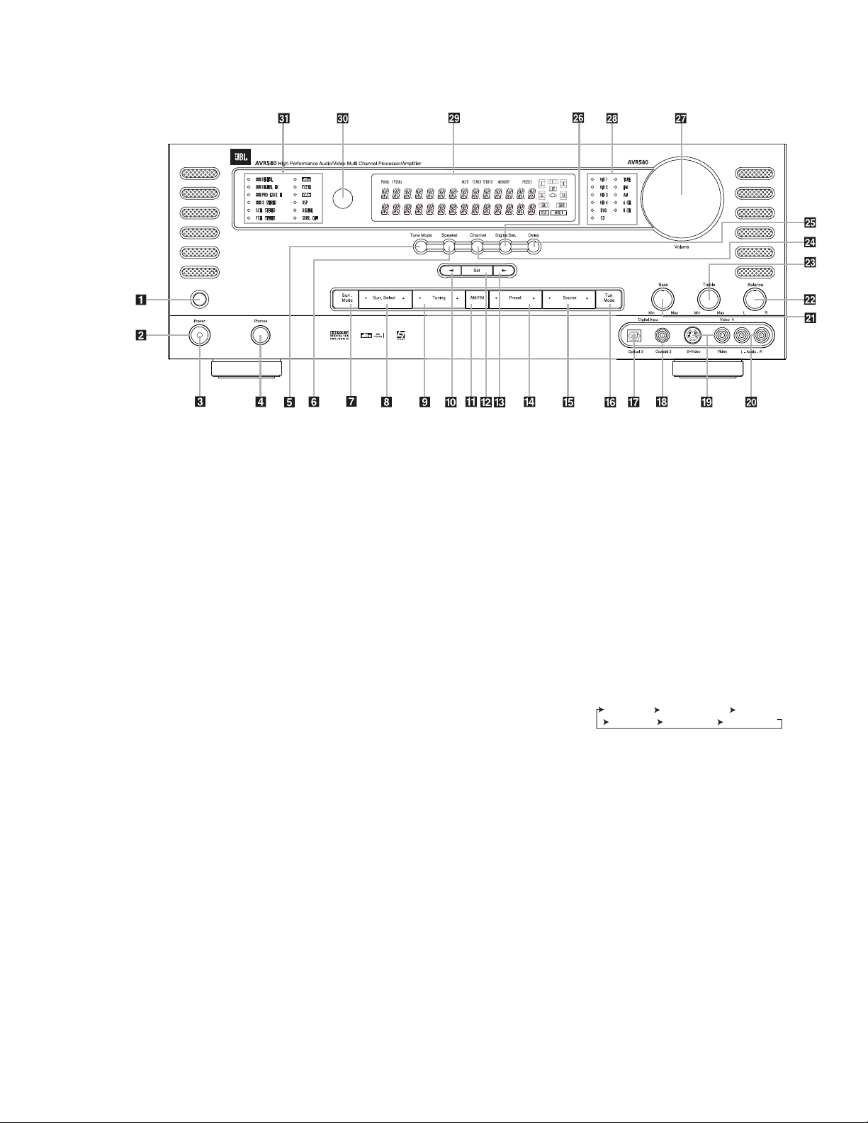
Bass Control Ôor Treble Control
Òuntil the desired setting is
achieved. You may also totally remove
the tone controls from the circuit so
that the output is “flat” at any time by
pressing the Tone Mode Button 5
and then pressing the /Buttons
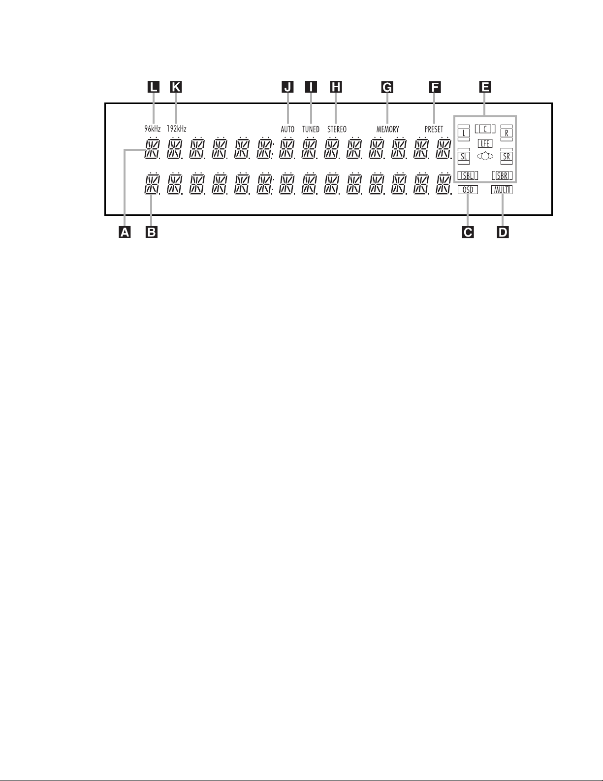
)# so that TONE OFF appears
in the on-screen display and the
Lower Display Line B.
• For private listening, plug the 1/4"
stereo phone plug from a pair of stereo
headphones into the front-panel
Headphone Jack 4. When the
headphone’s plug is connected, the
word HEADPHONE will scroll once
across the Lower Display Line B
and all speakers will be silenced.
When the headphone plug is removed,
the audio feed to the speakers will be
restored.
Surround Mode Selection
One of the most important features of the
AVR580 is its ability to reproduce a full
multichannel surround sound field from
digital sources, analog matrix surround-
encoded programs and standard stereo
programs.
Selection of a surround mode is based on
personal taste, as well as the type of
program source material being used. For
example, motion pictures or TV programs
bearing the logo of one of the major sur-
round-encoding processes, such as Dolby
Surround, DTS Stereo or UltraStereo,
may be played in either the Dolby Digital,
Dolby Pro Logic II-Movie, DTS Neo:6
Cinema, or Logic 7 Cinema surround
modes depending on the source material.
NOTE: Once a program has been encoded
with matrix surround information, it
retains the surround information as long
as the program is broadcast in stereo.
Thus, movies with surround sound may be
decoded via any of the analog surround
modes such as Dolby Pro Logic II-Movie,
Logic 7 Cinema or DTS Neo:6 Cinema,
when they are broadcast via conventional
TV stations, cable, pay-TV and satellite
transmission. In addition, a growing num-
ber of made-for-television programs,
sports broadcasts, radio dramas and music
CDs are also recorded in surround sound.
You may view a list of these programs at
the Dolby Laboratories Web site at
www.dolby.com.
Even when a program is not listed as car-
rying intentional surround information,
you may find that the Dolby Pro Logic II,
Logic 7 Enhance, DTS Neo:6, VMAx, Hall
or Theater modes often deliver enveloping
surround presentations through the use of
the natural information present in all
stereo recordings.
Surround modes may be changed at any
time by using either the front panel or
remote control. To select a new surround
mode from the front panel, first press the
Surround Mode Group Selector
Button 7until the desired major sur-
round mode group such as Dolby, DTS
or Logic 7 is selected. Next, press the
Surround Mode Selector Button 8
to choose the specific individual surround
mode.
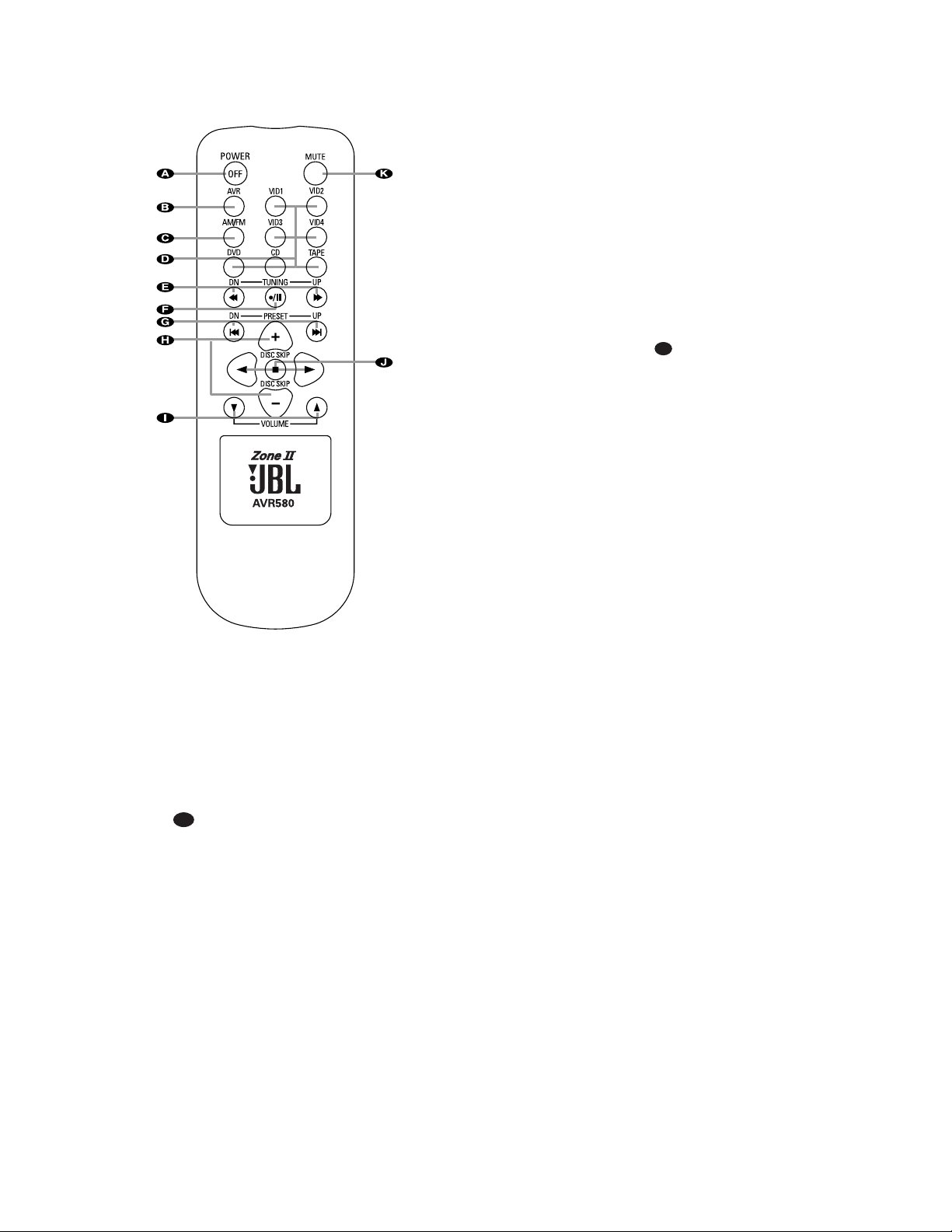
To select a surround mode using the
remote, press the button for the major
surround mode group that includes the
mode you wish to choose from: Dolby
w,DTS Surround x,DTS Neo:6
,Logic 7 y,Stereo or DSP
Surround k. The first press of the but-
ton will show the current mode from that
group if it is already in use, or the first
available mode if you are currently using
another mode. To cycle through the avail-
able modes in that group, press the but-
ton again until the desired mode appears
in the Lower Display Line Band the
on-screen display.
As the surround modes change, the
current mode will light in orange in the
Surround Mode Indicators ˘list on
the front panel.
The Dolby Digital, Dolby Digital EX and
DTS 5.1, DTS-ES Matrix and DTS-ES
Discrete modes may only be selected
when a digital input is in use. In addition,
when a digital source is present, the
AVR580 will automatically select and
switch to the correct mode, regardless
of the mode that has been previously
selected. For more information on
selecting digital sources, see the Digital
Audio Playback section below.
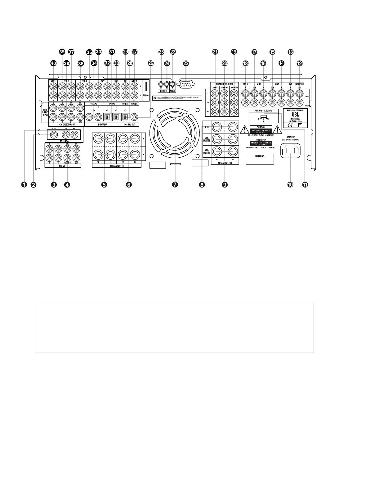
When the 6-channel/8-channel direct
inputs are in use there is no surround
processing, as these inputs take the ana-
log output signals from an optional,
external DVD-Audio or SACD player, or
another source device and carry them
straight through to the volume control
without any further digital processing.
When your AVR580 has been configured
for 6.1/7.1 operation with both left and
right surround back speakers installed,
selecting a 6.1-channel surround mode,
such as Dolby Digital EX or DTS-ES 6.1
Matrix, will result in both surround back
speakers playing the same information
for the surround back channel. The sur-
round back left and right speakers will
only play discrete information when
a 7-channel mode is selected, such
as Logic 7/7.1 Cinema or Music, or
7-Channel Stereo, or if the 8-Channel
Direct Input source is in use and is
providing discrete information for the
surround back channels.
To listen to a program in traditional two-
channel stereo, using the front left and
front right speakers only (plus the sub-
woofer, if installed and configured), press
the
Stereo Button until SURR
OFF appears in the Main Information
Display ˜, or press the Surround Mode
Group Selector 7until the Stereo
modes appear in the on-screen display and
Lower Display Line B. Next, press the
Surround Mode Select Button 8until
SURROUND OFF appears in the on-
screen display and Lower Display
Line B.
Digital Audio Playback
Digital audio is a major advancement over
older analog surround processing systems
such as Dolby Pro Logic. It delivers five dis-
crete channels: left front, center, right
front, left surround and right surround.
Each channel reproduces full frequency
range (20Hz to 20kHz) and offers dramati-
cally improved dynamic range and signifi-
cant improvements to signal-to-noise
ratios. In addition, digital systems have the
capability to deliver an additional channel
that is specifically devoted to low-frequency
information. This is the “.1” channel
referred to when you see these systems
described as “5.1,” “6.1” or “7.1”. The bass
channel is separate from the other chan-
nels, but since it is intentionally band-
width-limited, sound designers have given
it that unique designation.
Dolby Digital
Dolby Digital is a standard part of DVD,
and is available on specially encoded LD
discs and satellite broadcasts and it is
a part of the high-definition television
(HDTV) system.
29
29
30
32
An optional, external RF demodulator is
required to use the AVR580 to listen to
the Dolby Digital soundtracks available
on laser discs. Connect the RF output of
the LD player to the demodulator and
then connect the digital output of the
demodulator to the Optical or Coaxial
Inputs &* of the AVR580. No
demodulator is required for use with DVD
players or DTS-encoded laser discs.
DTS
DTS is another digital audio system that
is capable of delivering 5.1 or 6.1 discrete
or matrix sound field reproduction.
Although both DTS and Dolby Digital are
digital, they use different methods of
encoding the signals, and thus they
require different decoding circuits to con-
vert the digital signals back to analog.
DTS-encoded soundtracks are available
on select DVD and LD discs, as well as
on special audio-only DTS discs. You may
use any LD or CD player equipped with a
digital output to play DTS-encoded discs
with the AVR580. All that is required is to
connect the player’s output to either an
Optical or Coaxial Input on the rear
panel or front panel
&*.
In order to listen to DVDs encoded with
DTS soundtracks, the DVD player must be
compatible with the DTS signal as indi-
cated by a DTS logo on the player’s front
panel. Early DVD players may not be able
to play DTS-encoded DVDs. This does not
indicate a problem with the AVR580, as
some players cannot pass the DTS signal
through to the digital outputs. If you are
in doubt as to the capability of your DVD
player to handle DTS discs, consult the
player’s owner’s manual.
NOTE: Some DVD players have a default
setting that does not pass through the
DTS signal. Before playing DVDs with a
DTS soundtrack, make certain that the
settings in your DVD player have been
properly adjusted
so that DTS audio is
passed through. Consult the owner’s
manual for your DVD player for more
information on making these settings.
Selecting a Digital Source
To utilize either digital mode, you must
have properly connected a digital source
to the AVR580. Connect the digital out-
puts from DVD players, HDTV receivers,
satellite systems or CD players to the
Optical or Coaxial Inputs &* .
In order to provide a backup signal and a
source for analog stereo recording, the
analog outputs provided on digital source
equipment should also be connected to
their appropriate inputs on the AVR580
rear panel (e.g., connect the analog stereo
audio output from a DVD to the DVD
Audio Inputs kon the rear panel when
you connect the source’s digital outputs).
If you have not already configured an
input for a digital source using the on-
screen menus as shown on page 22, first
select the input using the remote or front-
panel controls as outlined in this manual.
Next, select the digital source by press-
ing the Digital Select Button qP
and then using the /¤Buttons n
on the remote or the /Selector
Buttons )# on the front panel to
choose any of the OPTICAL or
COAXIAL
inputs, as they appear in
the Upper Display Line Aor on-screen
display. When the digital source is play-
ing, the AVR580 will automatically detect
which type of digital data stream is being
decoded and display that information in
the Upper Display Line A.
Digital Bitstream Indicators
When a digital source is playing, the
AVR580 senses the type of bitstream data
that is present. Using this information, the
correct surround mode will automatically
be selected. For example, DTS bitstreams
will cause the unit to switch to DTS
decoding, and Dolby Digital bitstreams
will enable Dolby Digital decoding. When
the unit senses PCM data from CDs and
LDs, it will allow the appropriate surround
sources to be selected manually. Since
the range of available surround modes is
dependent on the type of digital data that
is present, the AVR580 uses display indi-
cators to let you know what type of signal
is present. This will help you to under-
stand the choice of modes.
To help you see which type of digital
source is playing, the Surround Mode
Indicators ˘in combination with the
Information Display ˜also serve as
bitstream indications to show which type
of bitstream is present, as well as the
surround mode in use, if applicable.
Digital: When the Dolby Digital
or Dolby Digital EX logo is lit, a Dolby
Digital bitstream is being received.
Depending on the settings on the source
player and specific surround information
and number of channels on the disc,
a number of surround modes are possi-
ble. For discs with full 5.1 audio, only
the Dolby Digital and VMAx modes are
available.
DTS: When the DTS logo lights, a DTS
bitstream is being received. When the
unit senses this type of data, only the
applicable DTS mode may be used.
PCM: When the word DIGITAL lights, a
standard Pulse Code Modulation, or PCM,
signal is being received. This is the type
of digital audio used by conventional
compact disc and laser disc recordings.
When a PCM bitstream is present, all
modes except Dolby Digital and DTS are
available.
MP3: When MP3 appears on the
Lower Display Line Ba compatible
MPEG 1/Layer 3 digital signal is being
received. This is the popular audio format
used by many computer programs for
recording compressed audio files. When
an MP3 bitstream is present, the sound
will automatically be played in the Stereo
(Surround Off) mode. The surround modes
are not available during MP3 playback.
There are many different forms of MP3
encoding available and the format is used
at a number of different bit rates. The
AVR580 may not be compatible with all
forms of MP3, particularly when the data
file is encoded at 128kb/s or above.
Speaker/Channel Indicators
In addition to the bitstream indicators,
the AVR580 features a set of unique
channel-input indicators that tell you how
many channels of digital information are
being received and/or whether the digital
signal is interrupted. (See Figure 9.)
Figure 9
These indicators are the
L/C/R/LFE/SL/SR/SBL/SBR letters that
are inside the center boxes of the
Speaker/Channel Input Indicators E
in the front-panel Main Information
Display ˜. When a standard analog
signal is in use, only the “L” and “R” indi-
cators will light, as
analog signals have
only left and right channels.
Digital signals, however, may have two,
five, six or seven channels, depending on
34
31
34
31
34
31
33
the program material, the method of
transmission and the way in which it was
encoded. When a digital signal is playing,
the letters in these indicators will light in
response to the specific signal being
received. It is important to note that
although Dolby Digital, for example, is
referred to as a “5.1” system, not all
Dolby Digital DVDs or programs are
encoded for 5.1. Thus, it is sometimes
normal for a DVD with a Dolby Digital
soundtrack to trigger only the “L” and “R”
indicators.
NOTE: Many DVD discs are recorded
with both “5.1” and “2.0” versions of the
same soundtrack. When playing a DVD,
always be certain to check the type of
material on the disc. Most discs show
this information in the form of a listing or
icon on the back of the disc jacket. When
a disc does offer multiple soundtrack
choices, you may have to make some
adjustments to your DVD player (usually
with the “Audio Select” button or in a
menu screen on the disc) to send a full
5.1 feed to the AVR580. It is also possible
for the type of signal feed to change dur-
ing the course of a DVD playback. In
some cases, the previews of special
material will only be recorded in 2.0
audio, while the main feature is available
in 5.1 audio. The AVR580 will automati-
cally sense changes to the bitstream and
channel count and reflect them in these
indicators.
The letters used by the Speaker/
Channel Input Indicators Ealso flash
to indicate when a bitstream has been
interrupted. This will happen when a digi-
tal input source is selected before the
playback starts, or when a digital source
such as a DVD is paused. The flashing
indicators remind you that the playback
has stopped due to the absence of a digi-
tal signal and not through any fault of the
AVR580. This is normal, and the digital
playback will resume once the playback
is started again.
Night Mode
A special feature of Dolby Digital is the
Night mode, which enables specially
encoded Dolby Digital input sources to be
played back with full digital intelligibility
while reducing the minimum peak level
by 1/4 to 1/3. This prevents abruptly loud
transitions from disturbing others, with-
out reducing the impact of the digital
source. The Night mode is available only
when Dolby Digital signals with special
data are being played.
The Night mode may be engaged when a
Dolby Digital DVD is playing by pressing
the Night Mode Button lon the
remote. Next, press the /¤Buttons
nto select either the middle range or
full-compression versions of the Night
mode. To turn the Night mode off, press
the /¤Buttons nuntil the mes-
sage in the lower third of the video dis-
play and in the Lower Display Line B
reads D-RANGE OFF.
The Night mode may also be selected to
always be on at either level of compres-
sion using the options in the DOLBY
menu. See page 23 for information on
using the menus to set this option.
IMPORTANT NOTES ON DIGITAL
PLAYBACK:
• When the digital playback source is
stopped, or in a pause, fast forward or
chapter search mode, the digital audio
data will momentarily stop, and the
channel position letters inside the
Speaker/ Channel Input Indicators
Ewill flash. This is normal and does
not indicate a problem with either the
AVR580 or the source machine. The
AVR580 will return to digital playback
as soon as the data is available and
when the machine is in a standard
play mode.
• Although the AVR580 will decode virtu-
ally all current DVD movies, CDs and
HDTV sources, it is possible that some
future digital sources may not be com-
patible with the AVR580.
• Not all digitally encoded programs
contain full 5.1- or 6.1-channel audio.
Consult the program guide that accom-
panies the DVD or laser disc to deter-
mine which type of audio has been
recorded on the disc. The AVR580 will
automatically sense the type of digital
surround encoding used and adjust to
accommodate it.
• When a digital source is playing, you
may not be able to select some of the
analog surround modes such as Dolby
Pro Logic II, Dolby 3, Stereo, Hall,
Theater or Logic 7.
• When a Dolby Digital or DTS source
is playing, it is not possible to make
an analog recording using the Tape
Outputs and Video 1 or Video 2
Audio Outputs .However, the
digital signals will be passed through
to the Digital Audio Outputs gi.
PCM Audio Playback
PCM (Pulse Code Modulation) is the non-
compressed digital audio system used for
compact discs and laser discs. The digital
circuits in the AVR580 are capable of
high-quality digital-to-analog decoding,
and they may be connected directly to
the digital audio output of your CD or
LD player.
Connections may be made to either the
rear-panel Optical or Coaxial Inputs
or the front-panel Digital Inputs
&*.
To listen to a PCM digital source, first
select the input for the desired source
(e.g., CD). Next press the Digital Select
Button Pqand then use the /¤
Buttons non the remote, or the /
Selector Buttons)# on the front
panel, until the desired choice appears in
the Main Information Display ˜.
During PCM playback, you may select
any Surround mode except Dolby Digital
or DTS.
MP3 Audio Playback
The AVR580 is one of the few receivers
equipped for onboard decoding for the
MP3 audio format used by computers and
portable audio devices. By offering MP3
decoding, the AVR580 is able to deliver
precise conversion of the digital signals
to an analog output, along with the bene-
fits of listening to the MP3 audio through
the AVR580’s high-current amplifier and
the speakers from your surround system,
rather than the smaller speakers and low-
powered amplifiers typically used with
computers.
To take advantage of the AVR580’s MP3
capabilities, simply connect the PCM out-
put of a computer’s sound card or the
PCM output of a portable digital audio
device to either the rear-panel Digital
Inputs or the front-panel Digital
Inputs &*. When the digital signal is
available, the Lower Display Line B
will indicate that an MP3 bitstream is
present, and the audio will begin playing.
NOTES:
• The AVR580 is only capable of playing
signals in the MP3 (MPEG 1/Layer 3)
format. It is not compatible with other
computer audio codecs.
34
31
34
31
39
36
33
continued on p. 35
34
OPERATION
Surround Mode Chart
MODE FEATURES
Dolby Digital Available only with digital input sources encoded with Dolby Digital data. It provides up to five separate main audio channels and
a special dedicated Low-Frequency Effects channel.
Dolby Digital EX Available when the receiver is configured for 6.1/7.1-channel operation, Dolby Digital EX is the latest version of Dolby Digital.
When used with movies or other programs that have special encoding, Dolby Digital EX reproduces specially encoded sound
tracks so that a full 6.1/7.1 sound field is available. When the receiver is set for 6.1/7.1 operation and a Dolby Digital signal is
present, the EX mode is automatically selected. Even if specific EX encoding is not available to provide the additional channel,
the special algorithms will derive a 6.1/7.1 output.
DTS 5.1 When the speaker configuration is set for 5.1-channel operation, the DTS 5.1 mode is available when DVD, audio-only music or
laser discs encoded with DTS data are played. DTS 5.1 provides up to five separate main audio channels and a special dedicated
low-frequency channel.
DTS-ES 6.1 Matrix When the speaker configuration is set for 6.1/7.1 operation, playback of a DTS-encoded program source will automatically trigger
DTS-ES 6.1 Discrete the selection of one of the two DTS-ES modes. Newer discs with special DTS-ES discrete encoding will be decoded to provide
six discrete, full-bandwidth channels plus a separate low-frequency channel. All other DTS discs will be decoded using the
DTS-ES Matrix mode, which creates a 6.1-channel sound field from the original 5.1-channel soundtrack.
Dolby Pro Logic II Dolby Pro Logic II is the latest version of Dolby Laboratory’s benchmark surround technology that decodes full-range, discrete left,
Movie center right, right surround and left surround channels from either matrix surround-encoded programs and conventional stereo
Music sources when an analog input is in use. The Dolby Pro Logic II Movie mode is optimized for movie soundtracks, while the Dolby
Emulation Pro Logic II Music mode should be used with musical selections. The Dolby Pro Logic II Emulation mode re-creates original Dolby
Pro Logic processing for those who prefer that presentation.
Logic 7 Cinema Logic 7 is an advanced mode that extracts the maximum surround information from either surround-encoded programs or
Logic 7 Music conventional stereo material. Depending on the number of speakers in use and the selection made in the SURROUND
Logic 7 Enhance SELECT menu, the “5.1” versions of Logic 7 modes are available when the 5.1 option is chosen, while the “7.1” versions of
Logic 7 produce a full sound field presentation, including back surround speakers when the “6.1/7.1” option is chosen.
The Logic 7 C (or Cinema) mode should be used with any source that contains Dolby Surround or similar matrix encoding.
Logic 7 C delivers increased center-channel intelligibility, and more accurate placement of sounds with fades and pans that are
much smoother and more realistic than with other decoding techniques. The Logic 7 M or Music mode should be used with
analog or PCM stereo sources. Logic 7 M enhances the listening experience by presenting a wider front soundstage and greater
rear ambience. Both Logic 7 modes also direct low-frequency information to the subwoofer (if installed and configured) to deliver
maximum bass impact. The Logic 7 E (or Enhance) mode, available only when the 5.1 option is chosen, is an extension of the
Logic 7 mode that is primarily used with musical programs. Logic 7 adds additional bass enhancement that circulates low fre
quencies in the 40Hz to 120Hz range to the front and surround speakers to deliver a less localized soundstage that appears
broader and wider than when the subwoofer is the sole source of bass energy.
DTS Neo:6 Cinema These two modes are available when any analog source is playing to create a six-channel surround presentation
DTS Neo:6 Music from conventional matrix-encoded and traditional stereo sources. Select the Cinema version of Neo:6 when a
program with any type of analog matrix surround encoding is present. Select the Music version of Neo:6 for
optimal processing when a nonencoded, two-channel stereo program is being played.
Dolby 3 Stereo Uses the information contained in a surround-encoded or two-channel stereo program to create center-channel information. In
addition, the information that is normally sent to the rear-channel surround speakers is carefully mixed in with the front-left and
front-right channels for increased realism. Use this mode when you have a center channel speaker but no surround speakers.
Theater The Theater mode creates a sound field that resembles the acoustic feeling of a standard live-performance theater.
Hall 1, Hall 2 The two Hall modes create sound fields that resemble a small (Hall 1) and medium-sized (Hall 2) concert hall.
VMAx Near When only the two front-channel loudspeakers are used, JBLs patented VMAx mode delivers a three-dimensional sound space
VMAx Far with the illusion of “phantom speakers” at the center and surround positions. The VMAx N, or “Near Field,” mode should be
selected when your listening position is less than five feet from the speakers. The VMAx F, or “Far Field,” mode should be
selected when your listening position is greater than five feet from the speakers. The VMAx modes are also available using the
Headphones Output 4. When head phones are being used, the Far Field mode will appear to push the sound field away from
your ears, reducing the “inside the head” sensation often experienced when using headphones.
5-Channel Stereo This mode takes advantage of multiple speakers to place a stereo signal at both the front and back of a room.
7-Channel Stereo Depending on whether the AVR has been configured for either 5.1 or 6.1/7.1 operation, one of these modes, but not both,
is available at any time. Ideal for playing music in situations such as a party, it places the same signal at the front-left and
surround-left, and front-right and surround-right speakers. The center channel is fed a summed mono mix of the in-phase
material of the left and right channels.
Surround This mode turns off all surround processing and presents the pure left- and right-channel presentation of two-channel stereo
Off (Stereo) programs.
35
• The digital audio input signal may be
either optical or coaxial, but the signal
must be in the PCM format. Direct con-
nection of USB or serial data outputs is
not possible, even though the signals
are in the MP3 format. If you have any
questions about the data output format
from your computer or a sound card,
check with the device’s owner’s manual
or contact the manufacturer’s technical
support area.
• Due to the wide variation in MP3 for-
mats and encoding speeds, it is possi-
ble that the AVR580 may not be com-
patible with all MP3 input signals. Some
may produce unacceptable results and
some may not be decoded. This is not
a fault of either the computer or the
AVR580, but rather a by-product of the
unpredictable nature of MP3 playback.
Tuner Operation
The AVR580’s tuner is capable of tuning
AM, FM and FM Stereo broadcast sta-
tions. Stations may be tuned manually,
or they may be stored as favorite station
presets and recalled from a 30-position
memory.
Region Selection
The AVR’s FM tuner must be set for com-
patibility with the television format and
radio broadcasts in your area. Using the
Region Selector located on the rear
panel of the receiver, select the position
corresponding to the country in which you
are using the receiver: C, S or K.
Refer to the chart below to determine the
proper setting. For other countries, con-
sult with your dealer or distributor to
determine the correct setting.
Country
Region Selector Switch
China C
Hong KongC
IndonesiaS
Korea (South) K
MalaysiaS
SingaporeS
ThailandS
Depending on the electrical requirements in
your area or the wiring in your home, the
power cords included with your AVR may not
be the correct ones, and you may need to
contact your local JBL distributor to obtain
the correct power cord.
IMPORTANT NOTE: Any adjustments
made to the Region Selector will
not take effect unless the unit is first fully
turned off by pressing the Main Power
Switch 1until it pops out and the word
“OFF” appears on the top of the button.
Station Selection
1. Press the AM/FM Tuner Select
Button g
ç
on the remote to
select the tuner as an input. The tuner
may be selected from the front panel
by pressing
either the Input Source
Selector %until the tuner is active
or the Tuner Band Selector !at
any time.
2. Press the AM/FM Tuner Select
Button g
ç
or Tuner Band
Selector !again to switch between
AM and FM so that the desired fre-
quency band is selected.
3. Press the Tuner Mode Button ^s
to select manual or automatic tuning.
When the AUTO Indicator Jis lit in the
Main Information Display ˜the tuner
will only stop at those stations that have a
strong enough signal to be received with
acceptable quality.
When the AUTO Indicator Jis not lit,
the tuner is in a manual mode and will
stop at each frequency increment in the
selected band.
4. To select stations, press the Tuning
Selector Button 9u
é
. When
the AUTO Indicator Jis lit, press
the button to cause the tuner to search
for the next highest- or lowest-fre-
quency station that has an acceptable
signal. Hold the Tuning Selector
Button 9u
é
to scan through
the stations with acceptable signals.
Press the Tuner Mode Button ^s
to switch to the manual tuning mode,
in which each press of the Tuning
Selector Button 9u
é
ad-
vances one frequency increment; press
and hold the selector button to scan
through all frequency increments.
When tuning FM stations in the Auto
mode, the tuner will only select stereo
stations. To tune to the next station,
switch to the manual tuning mode and
press the button again. If the STEREO
Indicator His not lit, tap the Tuning
Selector Button 9u
é
to advance
one frequency increment at a time, or
press and hold it to locate a specific sta-
tion. When the TUNED Indicator I
lights, the station is properly tuned and
should be heard with clarity.
5. Stations may also be tuned directly by
pressing the Direct Button t, and
then pressing the Numeric Keys r
that correspond to the station’s fre-
quency. The desired station will auto-
matically be tuned. If you press an
incorrect button while entering a direct
frequency, press the Clear Button
to start over.
NOTE: When the FM reception of a
station is weak, audio quality will be
increased by switching to Mono mode
by pressing the Tuner Mode Button
^suntil the STEREO Indicator H
goes out.
Preset Tuning
Using the remote, up to 30 stations may
be stored in the AVR580’s memory for
easy recall using the front-panel controls
or the remote.
To enter a station into the memory, first
tune the station using the steps outlined
above. Then:
1. Press the Memory Button on the
remote. The MEMORY Indicator G
will light and flash in the Main
Information Display ˜.
2. Within five seconds, press the
Numeric Keys rcorresponding to
the location where you wish to store
this station’s frequency. Once entered,
the preset number will appear in the
Main Information DIsplay ˜.
3. Repeat the process after tuning any
additional stations to be preset.
Recalling Preset Stations
• To manually select a station previously
entered in the preset memory, press
the Numeric Keys rthat corre-
spond to the desired station’s memory
location.
• To manually tune through the list of
stored preset stations one by one,
press the Preset Stations Selector
Buttons $
©
on the front
panel or remote.
Tape Recording
In normal operation, the audio or video
source selected for listening through the
AVR580 is sent to the record outputs.
This means that any program you are
watching or listening to may be recorded
33
35
34
36
simply by placing machines connected to
the outputs for Tape Outputs or
Video 1/Video 2 Audio and Video
Outputs fi‡ in the Record
mode.
When a digital audio recorder is connect-
ed to the Digital Audio Outputs gi,
you are able to record the digital signal
using a CD-R, MiniDisc or other digital
recording system.
NOTES:
• The digital outputs are active only
when a digital signal is present, and
they do not convert an analog input to
a digital signal, or change the format
of the digital signal. In addition, the
digital recorder must be compatible
with the output signal. For example,
the PCM digital input from a CD player
may be recorded on a CD-R or
MiniDisc, but Dolby Digital or DTS
signals may not.
• Please make certain that you are
aware of any copyright restrictions on
any material you copy. Unauthorized
duplication of copyrighted materials is
prohibited by law.
Output Level Trim Adjustment
Normal output level adjustment for the
AVR580 is established using the test tone,
as outlined on pages 27 – 29. In some
cases, however, it may be desirable to
adjust the output levels using program
material such as a test disc, or a selection
you are familiar with. Additionally, the
output level for the subwoofer can only
be adjusted using this procedure.
To adjust the output levels using program
material, first
set the reference volume for
the front left and front right
channels
using the Volume Control ı
î
.
If you are using a disc with test signals
or an external signal generator as the
source from which to trim the output lev-
els, you may use the EzSet feature of the
remote to guide you to the correct SPL
level. To use the remote for this purpose,
press and quickly release the SPL
Selector Button to activate the
sensor. While the test tone is circulating,
the Program/SPL Indicator cwill
change color to indicate the level. Adjust
the level using the /¤Buttons n
until the LED lights green for all channels.
When it is red the level is too high; when
it is amber the level is too low. Press the
SPL Selector Button to turn the
sensor and indicator off.
Once the reference level has been set,
press the Channel Select Button m
and FRONT L LEVEL will appear
in the Lower Display Line B. To
change the level, first press the Set
Button p, and then use the /¤
Buttons nto raise or lower the level.
DO NOT use the volume control, as this
will alter the reference setting.
Once the change has been made, press
the Set Button pand then press the
/¤Buttons nto select the next
output channel location that you wish to
adjust. To adjust the subwoofer level,
press the /¤Buttons nuntil
WOOFER LEVEL appears in the
Main Information Display ˜or on-
screen display.
Repeat the procedure as needed until all
channels requiring adjustment have been
set. When all adjustments have been
made and no further adjustments are
made for five seconds, the AVR580 will
return to normal operation.
The channel output for any input may
also be adjusted using the full-OSD
on-screen menu system. First, set the
volume to a comfortable listening level
using the Volume Control ı
î
.
Then, press the OSD Button vto
bring up the MASTER MENU
(Figure 1). Press the ¤Button nuntil
the on-screen cursor is next to the
CHANNEL ADJUST line. Press
the Set Button pto activate the
CHANNEL ADJUST menu.
Once the menu appears on your video
screen, first use the /¤Buttons n
to move the on-screen cursor so that it
is next to the TEST TONE line. Press
the /Buttons oso that OFF
is highlighted. This will turn off the test
tone and allow you to use your external
test disc or other source material as the
reference. Then, use the /¤Buttons
nto select the channels to be adjusted.
At each channel position, use the /
Buttons oto change the output
level. Remember, the goal is to have the
output level at each channel be equal
when heard at the listening position.
If you wish to reset all the levels to their
original factory default of 0dB offset,
press the /¤Buttons nso that
the on-screen cursor is next to the
CHANNEL RESET line and press
the /
Buttons oso that the
word ON is highlighted.
After the levels
are reset, resume the procedure outlined
above to reset the levels to the desired
settings. When all adjustments are done,
press the /¤Buttons nto move the
on-screen cursor so that it is next to
BACK TO MASTER MENU and
then press the Set Button pif you
wish to go back to the main menu to
make other adjustments. If you have no
other adjustments to make, press the
OSD Button vto exit the menu
system.
NOTE: The output levels may be separately
trimmed for each digital and analog sur-
round mode. If you wish to have different
trim levels for a specific mode, select that
mode and then follow the instructions in
the steps shown earlier.
Memory Backup
This product is equipped with a memory
backup system that preserves the system
configuration information and tuner pre-
sets if the unit is accidentally unplugged
or subjected to a power outage. This
memory will last for approximately two
weeks, after which time all information
must be reentered.
37
37
37
40
41
41
40
39
36
33
37
The AVR580 is equipped with a number
of advanced features that add extra flexi-
bility to the unit’s operation. While it is
not necessary to use these features to
operate the unit, they provide additional
options that you may wish to use.
Surround Amplifier Channel
Assignment
The AVR580 is equipped with seven full-
power amplifier channels to allow for
complete 7.1-channel operation without
the need for additional external ampli-
fiers. However, in some installations you
may wish to use the traditional 5.1-chan-
nel configuration for the main listening
room, which allows the surround back
left/right amplifier channels to be used to
power speakers placed in a remote zone
location.
If you wish to use the Surround Back
channel amplifiers to power the remote
zone, you must change a setting in the
ADVANCED SELECT menu. To
make that change, first call up the menu
system by pressing the OSD Button v
to bring the MASTER MENU (Figure 1)
to the screen. Next, press the ¤Button
nuntil the cursor is next to the
ADVANCED line. Press the Set
Button pto enter the ADVANCED
SELECT menu (Figure 10).
Figure 10
To change the setting so that the
Surround Back amplifiers are fed by the
source selected through the Multiroom
system, press the /Buttons o
so that MR SP is highlighted in reverse
video and press the Set Button p.
Remember that once this setting is made
you will not be able to take advantage of
any of the 6.1/7.1-channel decoding or
processing modes, and that the speakers
used for the remote zone must be con-
nected
to the Surround Back/Multi-
room Speaker Outputs ª. The volume
for these speakers is set by the multi-
room system, as explained on page 39
of this manual.
Once this setting is made, you may press
the ¤Button nto make any of the
other adjustments available on this
menu. If no other adjustments are
needed, press the OSD Button v
to exit the menu system.
Display Brightness
The AVR580’s Main Information
Display ˜is set at a default brightness
level that is sufficient for viewing in a
normally lit room. However, in some
home theater installations, you may wish
to occasionally lower the brightness of
the display, or turn it off completely.
To change the display brightness setting
for a specific listening session, you will
need to make an adjustment in the
ADVANCED SELECT menu. To
start the adjustment, press the OSD
Button vto bring the MASTER
MENU to the screen. Press the ¤
Button n, until the on-screen
cursor is next to the
ADVANCED
line. Press the Set Button pto enter
the
ADVANCED SELECT
menu
(Figure 10).
To change the brightness setting, at the
ADVANCED
SELECT menu, make
certain that the on-screen cursor is
next to the VFD line, and press the
Button until the desired brightness
level is highlighted in the video display.
When FULL is highlighted, the display
is at its normal brightness. When HALF
is highlighted, the display is at half the
normal brightness level. When OFF is
highlighted, all of the indicators in the
Main Information Display ˜will go
dark. However, the Input Indicators ˆ
and the Surround Mode Indicators
˘, as well as the Power Indicator 3,
will always remain lit to remind you that
the unit is turned on.
Once the desired brightness level is
selected, it will remain in effect until it
is changed again or until the unit is
turned off.
If you wish to make other adjustments,
press the /¤Buttons nuntil the
on-screen cursor is next to the desired
setting or the BACK TO MASTER
MENU line and press the Set Button
p. If you have no other adjustments to
make, press the OSD Button vto exit
the menu system.
Turn-On Volume Level
As is the case with most audio/video
receivers, when the AVR580 is turned on,
it will always return to the volume setting
in effect when the unit was turned off.
However, you may prefer to always have
the AVR580 turn on at a specific setting,
regardless of what was last in use when
the unit was turned off. To change the
default condition so that the same vol-
ume level is always used at turn-on, you
will need to make an adjustment in the
ADVANCED SELECT
menu. To
start the adjustment, press the OSD
Button vto bring the MASTER
MENU (Figure 1) to the screen. Press the
¤Button n, until the on-screen
cursor is next to the ADVANCED
line.
Press the Set Button pto enter
the ADVANCED SELECT menu
(Figure 10).
At the ADVANCED SELECT menu
make certain that the on-screen cursor
is next to the VOLUME DEFAULT
line by pressing the /¤Buttons n
as needed. Next, press the Button
so that the word ON is highlighted
in the video display. Next, press the ¤
Button nonce so that the on-screen
cursor is next to the DEFAULT VOL
SET line. To set the desired turn-on vol-
ume, press the /Buttons o
until the desired volume level is shown
on the DEFAULT VOL SET line.
This setting may NOT be made with the
regular volume controls.
NOTE: Since the setting for the turn-on
volume cannot be heard while the setting
is being made, you may wish to deter-
mine the setting before making the
adjustment. To do this, listen to any
source and adjust the volume to the
desired level using the regular Volume
Controls ı
î
. When the desired
volume level to be used at turn-on is
reached, make a note of the setting as it
appears in the lower third of the video
screen or in the Lower Display Line
B. (A typical volume level will appear as
a negative number such as –25dB.) When
making the adjustment, use the /
Buttons oto enter this setting.
Unlike some of the other adjustments in
this menu, the turn-on volume default
will remain in effect until it is changed or
turned off in this menu, even when the
unit is turned off.
If you wish to make other adjustments,
press the /¤Buttons nuntil the
on-screen cursor is next to the desired
setting or the BACK TO MASTER
MENU line and press the Set Button
37
40
37
37
37
37
* ADVANCED SELECT *
SB AMPS:SB SP MR SP
VFD :FULL HALF OFF
VOLUME DEFAULT:OFF ON
DEFAULT VOL SET:25dB
SEMI OSD :OFF ON
SEMI OSD TIME OUT: 3S
FULL OSD TIME OUT:20S
BACK TO MASTER MENU
ADVANCED FEATURES
38
p. If you have no other adjustments to
make, press the OSD Button vto exit
the menu system.
Semi-OSD Settings
The semi-OSD system places one-line
messages at the lower third of the video
display screen whenever the Volume,
Input Source, Surround mode or tuner
frequency of any of the configuration set-
tings are changed. The semi-OSD system
is helpful in that it enables you to have
feedback on any control changes or
remote commands using the video dis-
play when it is difficult to view the front-
panel displays. However, you may occa-
sionally prefer to turn these displays off
for a particular listening session. You may
also want to adjust the length of time the
displays remain on the screen. Both of
those options are possible with the
AVR580.
To turn off the semi-OSD system, you
will need to make an adjustment in the
ADVANCED SELECT menu
(Figure 10). To start the adjustment, press
the OSD Button vto bring the
MASTER MENU to the screen. Press
the ¤Button n,until the on-screen
cursor is next to the ADVANCED
line. Press the Set Button pto enter
the ADVANCED SELECT menu.
At the ADVANCED SELECT
menu, make certain that the on-screen
cursor is next to the SEMI OSD
DEFAULT line by pressing the /¤
Buttons nas needed. Next, press the
Button so that the word OFF is
highlighted in the video display.
This setting is temporary and will remain
active only until it is changed or until the
AVR580 is turned off. Once the unit is
turned off, the semi-OSD displays will
remain activated, even if they were
switched off for the previous listening
session.
To change the length of time that the
semi-OSD
displays remain on the screen,
go to the ADVANCED
SELECT
menu as outlined earlier, and press the
/¤Buttons nas needed, until the
on-screen cursor is next to the SEMI
OSD TIME OUT line. Next, press
the /Buttons ountil the
desired time in seconds is displayed.
Unlike most of the other options in this
menu, this is a permanent setting
change, and the time-out entry will
remain in
effect until it is changed, even
when the unit is turned off.
If you wish to make other adjustments,
press the /¤Buttons nuntil the
on-screen cursor is next to the desired
setting or the BACK TO MASTER
MENU line and press the Set Button
p. If you have no other adjustments to
make, press the OSD Button vto exit
the menu system.
Full-OSD Time-Out Adjustment
The FULL OSD menu system is used
to simplify the setup and adjustment of
the AVR580, using a series of on-screen
menus. The factory default setting for
these menus leaves them on the screen
for 20 seconds after a period of inactivity
before they disappear from the screen
(Time-Out). Time-Out is a safety measure
to prevent image retention of the menu
text in your monitor or projector, which
might happen if it were left on indefinitely.
However, some viewers may prefer a
slightly longer or shorter period before
the Time-Out display.
To change the full-OSD Time-Out, you
will need to make an adjustment in the
ADVANCED SELECT menu
(Figure 10). To start the adjustment, press
the
OSD Button vto bring the
MASTER
MENU to the screen. Press
the ¤Button n, until the on-screen
cursor is next to the ADVANCED
line. Press the Set Button pto enter
the ADVANCED menu (Figure 10).
At the ADVANCED SELECT menu
(Figure 10), make certain that the on-
screen cursor is next to the FULL
OSD TIME OUT line by pressing the
/¤Buttons nas needed. Next,
press the /Buttons ountil
the desired time is displayed in seconds.
Unlike most of the other options in this
menu, this is a permanent setting
change, and the Time-Out entry will
remain in effect until it is changed, even
if the unit is turned off.
If you wish to make other adjustments,
press the /¤Buttons nuntil
the on-screen cursor is next to the
desired setting or the RETURN TO
MASTER MENU line and press the
Set Button p. If you have no other
adjustments to make, press the OSD
Button vto exit the menu system.
37
37
37
39
The AVR580 is fully equipped to operate
as the control center for a complete mul-
tiroom system that is capable of sending
one source to a second zone in the house
while a separate source is listened to in
the main room. In addition to providing
for control over the selection of the
remote source and its volume, the
AVR580 offers a comprehensive range of
options for powering the speakers in the
second zone.
Using the line-level Multiroom Audio
Outputs h, the selected source may
be fed to optional, external power
amplifiers that may be matched to the
specifics of the installation.
When the main room system is config-
ured for 5.1 operation, the Surround
Back Left/Right amplifier channels may
be used to power the remote zone so
that no additional amplifiers are
required.
In addition, the AVR580 includes a
remote IR sensor input so that remote
control commands from the Zone II
remote included with the unit may be
transmitted to the unit, while standard
IR input/output jacks allow the remote
zone’s commands to be sent to compatible
IR-controlled source devices.
Installation
Although simple remote room systems
may be installed by the average do-it-
yourself hobbyist, the complexity of your
multizone/multiroom system involves run-
ning wires inside of walls where the
services of a specially trained installer
may be required. Regardless of who does
the work, please remember that local
building codes may govern in-wall electri-
cal work, including proper specification
of any wiring used and the way in which
it is connected. You are responsible for
making certain that all multiroom instal-
lation work is done properly and in com-
pliance with all applicable codes and
regulations.
For standard installations, follow the
instructions shown on page 17 for the
connection of speaker wire and IR remote
wiring to the AVR580.
For installations where the Surround Back
Left/Right amplifier channels are used to
power the remote zone, make certain that
the system is configured for that type of
operation, as shown on page 36.
RS-232 Control
The AVR580 is rare among A/V receivers
in that it provides the capability for full
remote control from compatible comput-
ers or specialized remote control sys-
tems. RS-232 programming requires spe-
cialized programming knowledge and for
that reason we recommend that it only be
done by qualified installers. For more
information on using the RS-232 port for
remote control, please contact your local
JBL distributor.
Multiroom Setup
Once the audio and IR link connections
have been made, the AVR580 needs to
be configured for multiroom operation.
Press the OSD Button vto bring the
MASTER MENU (Figure 1) to the
screen. Press the ¤Button n,
until the on-screen cursor is next
to the MULTI-ROOM line. Press
the Set Button pto enter the
MULTI-ROOM SETUP menu
(Figure 11).
Figure 11
When the MULTI-ROOM SETUP
menu appears, the on-screen cursor
will be at the MULTI-ROOM line.
Since this line is used to turn the system
on and off, don’t make an adjustment
here unless you wish to turn the system
on at this time. To turn the system on,
press the Button so that ON is
highlighted. If you do not wish to turn the
system on at this time, or to proceed to
the next step, press the
¤
Button n
once so that the on-screen cursor is
next to the MULTI IN line.
At the MULTI IN line, press the /
Buttons ountil the desired input
to the multiroom system appears in the
highlighted video. When the selection
has been made, press the ¤Button n
once so that the on-screen cursor is
next to the MULTI VOL line.
At the MULTI VOL line, press the
/Buttons ountil the desired
volume level for the multiroom system is
entered. DO NOT use the regular volume
control knobs for this setting. When all
settings for the multiroom setup have
been made, press the /¤Buttons
nuntil the on-screen cursor is next
to the BACK TO MASTER MENU
line. If you have no other adjustments to
make, press the OSD Button vto exit
the menu system.
Multiroom Operation
When operating the AVR580 from a
remote room location where an IR sensor
link has been connected to the AVR580’s
rear-panel Multiroom IR Input d, you
may use either the main remote control
or the Zone II remote. To turn on the
multiroom feed, press any of the Input
Selector buttons on the Zone II remote
ç∂
or the main remote
eg.
Press the AVR Selector f
to turn
the unit on to the last source, or any of
the other Selector buttons to turn on to
a specific source.
As long as an IR feed to the AVR580 has
been established from the remote room,
using any of the buttons on either remote
will control the remote location volume
î
, change the tuner frequency
u
É
, change the tuner preset
©
or mute the output
˚
.
If the Remote IR Output Jack fon the
AVR580 is connected to an IR Input jack
on compatible audio components such as
CD, DVD or cassette players, the trans-
port functions of those machines may
also be controlled using the Transport
Controls `
ƒ˙∆
on either
remote control.
To turn the system off from the remote
room, press the Power Off Button
a
å
. Remember that the AVR580 may
be turned on or off from the remote room,
regardless of the system’s operation or
status in the main room.
NOTE: When the tuner is selected as the
source for the remote zone, any change
to the frequency or preset will also
change the station being listened to in
the main room, if the tuner is in use
there. Similarly, if someone in the main
room changes the station, the change
will also impact the remote room.
To activate the feed to the remote room,
while you are in the main listening room
where the AVR580 is located, press the
43
33
40
37
37
37
* MULTI-ROOM SETUP *
MULTI-ROOM:OFF ON
MULTI IN :FM PRESET01
MULTI VOL :25dB
BACK TO MASTER MENU
MULTIROOM OPERATION
40
Multiroom Button on the remote.
Next, press the Set Button p. Press
the /¤Buttons nto turn the
multiroom feed on or off. When the
multiroom system is on, the Multiroom
Indicator Dwill light in the Main
Information Display ˜, and the
Lower Display Line Bor OSD will
display MULTI ON. Press the Set
Button pto enter the setting.
When the multiroom system is turned on,
the input selected using the multiroom
menu will be fed to the Multiroom
Audio Outputs hon the rear panel.
The volume will be as set in the previous
selection, although it may also be
adjusted using an optional IR sensor and
the Zone II remote in the remote location,
or on the optional audio power amplifier
connected to the Multiroom Audio
Outputs h.
Once the multiroom system is turned on,
it will remain on even if the AVR580 is
placed in the Standby mode in the main
room by pressing the Power Off Button
å
or the System Power Control 2
on the front panel. To turn off the multi-
room system, even when the AVR is in
Standby mode in the main listening room,
press the Multiroom Button and
then the Set Button p. Press the
/¤Buttons nso that the
Multiroom Indicator Din the Main
Information Display ˜goes out, and
the Main Information Display ˜or
OSD will display MULTI OFF. Press
the Set Button pto enter the setting
and turn the unit off.
Even when the AVR580 is turned off in
the main room, the multiroom system
may be turned on at any time by pressing
the Multiroom Button , or any of
the Selector Buttons
∫ç∂
in
the remote room.
39
39
39
41
PROGRAMMING THE REMOTE
The AVR580 is equipped with a powerful
remote control that will control not only
the receiver’s functions, but also most
popular brands of audio and video equip-
ment, including CD players, cassette
decks, TV sets, cable boxes, VCRs, satel-
lite receivers and other home theater
equipment. Once the AVR580’s remote is
programmed with the codes for the pro-
ducts you own, it is possible to eliminate
most other
remotes and replace them
with the convenience of a single, universal
remote control.
Programming the Product
Codes
The AVR580 remote is factory-pro-
grammed for all AVR functions, as well as
those of JBL DVD players. In addition, by
following one of the methods below, you
may program the remote to operate a
wide range of devices from other manu-
facturers.
Direct Code Entry
This method is the easiest way to
program your remote to work with
different products.
1. Use the tables in the following pages
to determine the three-digit code or
codes that match both the product
type (e.g., VCR, TV) and the specific
brand name. If there is more than one
number for a brand, make note of the
different choices.
2. Turn on the unit you wish to program
into the AVR580 remote.
3. Press and hold both the Input
Selector efor the product you
wish to control (e.g., VCR, TV) and the
Mute Button at the same time.
When the red light under the Input
Selector estays lit and the
Program/SPL Indicator cturns
amber and begins flashing, release
the buttons. It is important that you
begin the next step within 20 sec-
onds.
4. Point the AVR580’s remote toward
the unit to be programmed, and enter
the first three-digit code using the
Numeric Keys r. If the unit turns
off, the correct code has been entered.
Press the Input Selector eagain,
and note that the red light will flash
three times before going dark to con-
firm the entry.
5. If the device to be programmed in
does NOT turn off, continue to enter
three-digit codes until the equipment
turns off. At this point, the correct
code has been entered. Press the
Input Selector eagain and note
that the red light under the Input
Selector ewill flash three times
before going dark to confirm the entry.
6. Try all of the functions on the remote
to make certain that the product oper-
ates properly. Keep in mind that many
manufacturers use a number of differ-
ent combinations of codes, so it is a
good idea to make certain that not
only the power control, but the vol-
ume, channel and transport controls
work as they should. If functions do
not work properly, you may need to
use a different remote code.
7. If a code cannot be entered to turn
the unit off, if the code for your prod-
uct does not appear in the tables in
this manual, or if not all functions
operate properly, try programming
the remote with the Auto Search
Method.
Auto Search Method
If the unit you wish to include in the
AVR580’s remote is not listed in the code
tables in this manual or if the code does
not seem to operate properly, you may
wish to program the correct code using
the Auto Search method that follows:
1. Turn on the unit that you wish to
include in the AVR580 remote.
2. Press the Input Selector efor the
type of product to be entered (e.g.,
VCR, TV) and the Mute Button
at the same time. Hold both
buttons
until the
red
light under the Input
Selector estays lit and the
Program/SPL Indicator c
turns
amber and begins flashing. The next
step must take place while the red
light is on, and it must begin within 20
seconds after the light appears.
3. Point the AVR580 remote toward the
unit to be programmed, and press
either the
or
¤
Button n. Each
press will send out a series of codes
from the remote’s built-in database.
When the unit being programmed
turns off, release the
/¤
Button
n, as that is your indication that the
correct code is in use.
4. Press the Input Selector e; the
red light under the Input Selector will
flash three times before going dark to
confirm the entry.
5. Try all of the functions on the remote
to make certain that the product oper-
ates. Keep in mind that many manu-
facturers use a number of different
combinations of codes, and it is a
good idea to make certain that not
only the power control works, but also
the volume, channel and transport
controls, as appropriate. If all func-
tions do not work properly, you may
need to Auto-Search for a different
code, or enter a code via the Direct
Code Entry method.
Code Readout
When the code has been entered using
the Auto Search method, it is always a
good idea to find out the exact code so
that it may be easily reentered if neces-
sary. You may also read the codes to
verify which device has been programmed
to a specific Control Selector button.
1. Press and hold both the Input
Selector efor the device whose
code you wish to find and the Mute
Button at the same time. The
Program/SPL Indicator cwill
turn amber and begin flashing, and
the red light under the Input
Selector ewill stay lit. Release
the buttons and begin the next step
within 20 seconds.
2. Press the Set Button p. The
Program/SPL Indicator cwill
then blink green in a sequence that
corresponds to the three-digit code,
with a one-second pause between
each digit. Count the number of blinks
between pauses to determine the digit
of the code. One blink is the number 1,
two blinks is the number 2, and so
forth. Ten blinks are used to
indicate a “0.
Example: One blink, followed by a one-
second pause, followed by six blinks, fol-
lowed by a one-second pause, followed
by ten blinks indicates that the code has
been set to 160.
For future reference, enter the setup
codes for the equipment in your system
here:
DVD ____________ CD____________
VID1/VCR ________ VID2/SAT ____
VID2/CBL ________ VID3/TV ______
VID4 ____________ TAPE ________
43
43
43
42
Learning Codes
In addition to using codes from the
remote’s internal code library, the
AVR580’s remote is able to “learn”codes
from remotes that may not be in the code
library. Also, you may use this function
to “learn over” the codes from a prepro-
grammed device to add functions not
included in the preprogrammed codes.
To learn or transfer codes from an IR
remote to the AVR580’s remote, follow
these steps:
1. Place the front of the original remote
with the code being sent so that it is
facing the IR Transmitter Window
bon the AVR580 remote “head-to-
head.” The remotes should be between
one and three inches apart.
2. Select the button on the remote that
you wish to use as the device selector
for the codes about to be entered.
This may be any of the Input
Selectors e.
3. Press the Input Selector ebutton
chosen and the Learn Button
at the same time. Hold these buttons
until the Program/SPL Indicator c
flashes amber and the light under the
device selector button turns red.
Release the buttons.
4. Press the button on the AVR580
remote that you wish to program. The
Program/SPL Indicator cwill
stop flashing.
5. Within five seconds, press and hold
the button on the original remote that
you wish to “teach” into the AVR580
remote. When the Program/SPL
Indicator cturns green three
times, release the button. The Program
Indicator will then begin to flash
amber again.
NOTE: If the Program/SPL Indicator
cturns red during Step 5, the pro-
gramming was not successful. Repeat
the steps to see whether the code
will “take.
6. Repeat Steps 4 through 6 for each
button on the source remote that you
wish to transfer to the AVR580 remote.
7. Once all codes have been transferred
from the original source remote to the
AVR580 remote, press the Learn
Button .
8. Repeat Steps 1 through 7 for any addi-
tional remotes you wish to “teach”
into the AVR580 remote.
Erasing Learned Codes
The AVR580’s remote allows you to
remove or erase the code learned into
a single button for a single device, to
remove or erase the code set for all the
codes that have been programmed into
specific device buttons, or to erase all
commands that have been learned to all
devices.
To erase a single learned code from within
a single device’s settings, follow these
steps:
1. Press and hold both the Input Selector
ewithin which the individual button
to be erased has been programmed and
the Learn Button .
2. When the LED under the Input
Selector turns red and the Program/
SPL Indicator cflashes amber,
release the buttons.
3. Press and release the Input Selector
eagain for the device within which
the individual button to be erased has
been programmed.
4. Press the 7Button rfour times.
5. Press and release the individual button
for which the code is to be erased. The
Program/SPL Indicator cwill blink
green two times and then return to
amber.
6. To erase other buttons within the same
device, press them as described in
Step 5.
7. When all buttons to be erased have
been pressed, press the Learn Button
to complete the process.
To erase all codes within a single device,
follow these steps:
1. Press and hold both the Input Selector
efor which you wish to erase the
codes and the Learn Button .
2. When the LED under the Input
Selector turns red and the Program/
SPL Indicator cflashes amber,
release the buttons.
3. Press and release the Input Selector
eagain for the device whose codes
you wish to erase.
4. Press the 8 Button rfour times.
5. The Program/SPL Indicator cwill
turn off and the red light under the
Input Selector will flash on and off
once to indicate that the codes have
been erased.
To erase all codes that have been pro-
grammed to all devices in the remote,
follow these steps:
1. Press any Input Selector efor
which you wish to erase the codes and
also the Learn Button .
2. When the LED under the Input
Selector turns red and the Program/
SPL Indicator cflashes amber,
release the buttons.
3. Press and release the Input Selector
eagain for the device whose codes
you wish to erase.
4. Press the 9Button rfour times.
5. The Program/SPL Indicator cwill
turn off and the red light under the
Input Selector will flash on and off
once to indicate that the codes have
been erased.
Macro Programming
Macros enable you to easily repeat
frequently used combinations of com-
mands with the press of a single button
on the AVR580’s remote control. Once
programmed, a macro will send out up to
19 different remote codes in a predeter-
mined sequential order, enabling you to
automate the process of turning on your
system, changing devices, or other com-
mon tasks. The AVR580’s remote can
store up to five separate macro command
sequences: one that is associated with
the Power On Button aand four
more that are accessed by pressing the
Macro Buttons .
1. Press the Mute Button and
the Macro Button to be pro-
grammed or the Power On Button
aat the same time. An Input
Selector ef will light red, and
the Program/SPL Indicator cwill
flash amber.
2. Enter the steps for the macro
sequence by pressing the button for
the actual command step. Although
the macro may contain up to 19 steps,
each button press, including those
used to change devices, counts as a
step. The Program/SPL Indicator
31
43
31
42
42
42
42
42
42
43
cwill flash green to confirm each
button press as you enter commands.
NOTE: While entering commands for
Power On/Off of any device during a
macro sequence, press the Mute Button
. DO NOT press the actual Power
button.
3. When all the steps have been
entered, press the Sleep Button
jto enter the commands. The red
light under the Input Selectors
ef will blink and then turn off.
Example: To program the Macro 1
button so that it turns on the AVR580,
TV and a cable box, follow these steps:
• Press the Macro 1 Button and
Mute Button at the same time
and then release them.
• Note that the Program/SPL
Indicator cwill flash amber.
• Press the AVR Selector f.
• Press the Mute Button to store
the AVR580’s Power On command.
• Press the VID 3 Input Selector
Button eto indicate the next
command is for “TV Power On.”
• Press the Mute Button to store
the TV Power On Command.
• Press the VID 2 Input Selector
Button eto
indicate the next com-
mand is for “Cable Power On.”
• Press the Mute Button to store
the Cable Power On command.
• Press the Sleep/Channel Up
Button jto complete the process
and store the macro sequence.
After following these steps, each time
you press the Macro 1 Button ,
the remote will send the Power
On/Off command.
Erasing Macro Commands
To remove the commands that have been
programmed into one of the Macro but-
tons, follow these steps:
1. Press the Mute Button and the
Macro Button that contains the
commands you wish to erase.
2. The Program/SPL Indicator c
will flash amber, and the LED under
the AVR Selector fwill turn red.
3. Within 10 seconds, press the
Surround Mode Selector/Channel
Down Button k.
4. The red LED under the AVR Selector
fwill go out, and the Program/
SPL Indicator cwill turn green
and flash three times before it
goes out.
5. When the Program/SPL Indicator
cgoes out, the Macro has been
erased.
Figure 12
Programmed Device Functions
Once the AVR580’s remote has been pro-
grammed for the codes of other devices,
press the appropriate Input Selector e
to change the remote from controlling the
AVR580 to controlling the additional prod-
uct. When you press any one of the selec-
tors, it will briefly flash in red to indicate
that you have changed the device being
controlled.
When operating a device other than the
AVR580, the controls may not correspond
exactly to the function printed on the
remote or button. Some commands, such
as the volume control, are the same as
they are with the AVR580. Other buttons
will change their function so that they
correspond to a secondary label on the
remote. For example, the Sleep and
Surround mode selector buttons also func-
tion as the Channel Up and Channel Down
buttons when operating most TV sets,
VCRs or cable boxes. The Channel Up/
Down indication is printed directly on the
remote. For many standard CD players,
cassette decks, VCRs and DVD functions,
the standard function icons are printed on
top of the buttons.
For some products, however, the function
of a particular button does not follow the
command printed on the remote. In order
to see which function a button controls,
consult the Function List tables on pages
46 and 47. To use those tables, first
check the type of device being controlled
(e.g., TV, VCR). Next, look at the remote
control diagram in Figure 12. Note that
each button has a number on it.
T
o find out what function a particular but-
ton has for a specific device, find the but-
ton number on the
Function List and then
look in the column for the device you are
controlling. For example, button number
45
is the Direct button for the AVR580,
but it is the “Favorite” button for many
cable television boxes and satellite
receivers. Button number 31 is the
Delay button for the AVR580, but the
Open/Close button for CD players.
NOTE: The numbers used to describe
the button functions in Figure 12 for the
purposes of describing how a button
operates are a different set of numbers
than those used in the rest of this manual
to describe the button functions for the
AVR580.
31
43
31
43
43
43
43
31
43
44
Notes on Using the AVR580 Remote
With Other Devices
• Manufacturers may use different code
sets for the same product category. For
that reason, it is important that you
check to see whether the code set you
have entered operates as many con-
trols as possible. If it appears that only
a few functions operate, check to see
whether another code set will work
with more buttons.
• When a button is pressed on the
AVR580 remote, the red light under
the Input Selector ef for the
product being operated should flash
briefly. If the Device Control Selector
flashes for some but not all buttons
for a particular product, it does NOT
indicate a problem with the remote
but rather that no function is pro-
grammed for the button being pushed.
Volume Punch-Through
The AVR580’s remote may be pro-
grammed to operate the Volume Control
and Mute functions of either
the TV or the AVR580 in conjunction with
any of the devices controlled by the
remote. For example, since the AVR580
will likely be used as the sound system
for TV viewing, you may wish to have the
AVR580’s volume activated, although the
remote is set to run the TV. Either the
AVR580 or TV volume control may be
associated with any of the remote’s
devices. To program the remote for
Volume Punch-Through, follow these
steps:
1. Press the Input Selector efor the
unit you wish to have associated with
the volume control and the Mute
Button at the same time until
the red light appears under the Input
Selector e;the Program/SPL
Indicator cwill flash amber.
2. Press the Volume Up Button ;
the Program/
SPL Indicator cwill
stop flashing and stay
amber
.
3. Press either the AVR Selector for
the Input Selector e, depending
on which system’s volume control you
wish to have active for the punch-
through mode. The Program/SPL
Indicator cwill blink green three
times and then go out to confirm the
data entry.
Example: To have the AVR580’s vol-
ume control activated even though
the remote is set to control the TV,
first press the Video 3/TV Input
Selector eand the Mute Button
at the same time. Next, press the
Volume Up Button , followed by
the AVR Selector f.
NOTE: Should you wish to return the
remote to the original configuration after
entering a Volume Punch-Through, you will
need to repeat the steps shown above.
However, press the same Input Selector
in Steps 1 and 3.
Channel Control Punch-
Through
The AVR580’s remote may be programmed
to operate so that the channel control
function for either the TV, cable or satellite
receiver used in your system may be used
in conjunction with one of the other
devices controlled by the remote. For
example, while using and controlling the
VCR, you may wish to change channels on
a cable box or satellite receiver without
having to change the device selected by
the AVR580 or the remote. To program
the remote for Channel Control Punch-
Through, follow these steps:
1. Press the Input Selector Button
ef for the device you wish to
have the channel control associated
with and the Mute Button at the
same time until the red light appears
under the Input Selector ef and
the Program/SPL Indicator c
flashes amber.
2. Press the Volume Down Button .
The Program/SPL Indicator cwill
stop flashing and stay amber.
3. Press and release the Input Selector
Button efor the device that will
be used to change the channels. The
Program/SPL Indicator cwill blink
green three times and then go out to
confirm the data entry.
Example: To control the channels using
your cable box or satellite receiver
while the remote is set to control the
VCR, first press the VID 1/VCR Input
Selector Button eand the Mute
Button at the same time. Next,
release them and press the Volume
Down Button , followed by the
VID 3/TV Input Selector Button e.
NOTE: To remove the Channel Control
Punch-Through and return the remote to
its original configuration, repeat the steps
shown in the example above. However,
press the same Input Selector in Steps 1
and 3.
Transport Control Punch-
Through
The AVR580’s remote may be programmed
to operate so that the Transport Control
Functions `(Play, Stop, Fast Forward,
Rewind, Pause and Record) for a VCR,
DVD or CD will operate in conjunction
with one of the other devices controlled by
the remote. For example, while using and
controlling the TV, you may wish to start or
stop your VCR or DVD without having to
change the device selected by the AVR580
or the remote. To program the remote for
Transport Control Punch-Through, follow
these steps:
1. Press the Input Selector ef for
the device you wish to have the chan-
nel control associated with and the
Mute Button at the same time
until the red light appears under the
Input Selector eand the Program/
SPL Indicator cflashes amber.
2. Press the Play Button `. The
Program/SPL Indicator cwill stop
flashing and stay amber.
3. Press and release the Input Selector
Button efor the device that will
be used to change the channels. The
Program/SPL Indicator cwill blink
green three times and then go out to
confirm the data entry.
Example: To control the transport of a
DVD player while the remote is set to
control the TV, first press the VID 3/TV
Input Selector Button eand the
Mute Button at the same time.
Next, release them and press the Play
Button `, followed by the DVD
Input Selector Button e.
NOTES:
To remove the Channel Control Punch-
Through and return the remote to its
original configuration, repeat the steps
in the example above. However, press
the same Input Selector in Steps 1
and 3.
The remote control is programmed at
the factory to include transport control
for JBL DVD players while the remote is
set to control the AVR.
43
43
40
43
40
43
40
43
40
43
43
40
45
Before programming the remote for
Volume, Channel or Transport Punch-
Through, make certain that any pro-
gramming needed for the specific TV,
CD, DVD, cable or satellite receivers has
been completed.
Reassigning Device Control
Selectors
Although each Input Selector eis nor-
mally assigned to the category of product
shown on the remote, it is possible to
reassign one of these buttons to operate a
second device of another type. For exam-
ple, if you have two VCRs but no satellite
receiver, you may program the “SAT” but-
ton to operate a second VCR. Before fol-
lowing the normal programming steps for
either Three-Digit entry or Auto Search
code entry, you must first reassign the but-
ton with the following steps:
1. Press the Input Selector eyou wish
to reassign and the Mute Button
at the same time until the red light
appears under the Input Selector e
and the Program/SPL Indicator c
flashes amber.
2. Press the Input Selector efor the
device you wish to program into the
reassigned button.
3. Enter the three-digit code for the spe-
cific model you wish the reassigned
button to operate.
4. Press the same Input Selector e
pressed in Step 1 once again to store
the selection. The red LED under the
reassigned Input Selector will flash
three times and then go out.
Example: To use the CBL/SAT button
to operate a second VCR, first press
the Video 2/CBL/SAT Input Selector
eand the Mute Button at the
same time until the red light glows
under the Video 2/CBL/SAT Button
e. Press the VCR Button e, fol-
lowed by the three-digit code for the
specific model you wish to control.
Finally, press the Video 2/CBL/SAT
Button eagain.
Resetting the Remote Memory
As you add components to your home
theater system, occasionally you may wish
to totally reprogram the remote control
without the confusion of any commands,
macros or ”Punch-Through“ programming
that you may have done. To do this, it is
possible to reset the remote to the original
factory defaults and command codes by
following these steps. However, once the
remote is reset, all commands or codes
that you have entered will be erased and
will need to be reentered:
1. Press any of the Input Selector
Buttons eand the ”O“ Button r
at the same time until the Program/
SPL Indicator cbegins to flash
amber.
2. Press the ”3“ Button rthree times.
3. The red LED under the Input Selector
ewill go out and the Program/SPL
Indicator cwill stop flashing and
turn green.
4. The Program/SPL Indicator c
will remain green until the remote is
reset. Note that this may take a while,
depending on how many commands are
in the memory that need to be erased.
5. When the Program/SPL Indicator
cgoes out, the remote has been
reset to the factory settings.
43
43
46
FUNCTION LIST
No. Button Name AVR Function DVD CD/CD-R Tape VCR (VID1) CBL (VID2) SAT (VID2) TV (VID3)
1Power On Power On Power On Power On Power On Power On Power On Power On Power On
2Power Off Power Off Power Off Power Off Power Off Power Off Power Off Power Off Power Off
3Mute Mute Mute Mute Mute Mute Mute Mute Mute
4AVR AVR Select
5DVD DVD Input Select DVD Select
6CD CD Input Select CD Select
7Tape Tape Input Select Tape Select
8VID 1 Video 1 Select VCR Select
9VID 2 Video 2 Select CBL Select SAT Select
10 VID 3 Video 3 Select TV Select
11 VID 4 Video 4 Select
12 AM/FM Tuner Select
13 6/8 Ch. Select
6/8 Ch. Input Select
14 Learn
15 Sleep Sleep Channel + Channel + Channel + Channel +
16 Test Test Tone TV/DVD Input Select TV/VCR TV/Cable TV/Sat TV/VCR
17 SPL EzSet/SPL
18 Volume Up Volume Up Input Level Up Volume Up Volume Up Volume Up Volume Up
19 Surround Select
Surround Mode Select
CDR Select Channel – Channel – Channel – Channel –
20 Night Night Mode Select
Subtitle On/Off
CDR Select
21 Multiroom Multiroom Select
22 Volume Down Volume Down
Input Level Down
Volume Down Volume Down Volume Down
23 Channel/Guide Channel Trim Title Info/Guide Info/Guide
24
Move/Adjust Up Up Up Up Up Up
25 Speaker/Menu Speaker Adjust Menu Intro Scan Menu Menu Menu Menu
26
Move/Adjust Left Left Left Left Left Left
27 Set Set Enter Enter Enter Enter Enter
28
Move/Adjust Right Right Right Right Right Right
29 Digital/Exit
Digital Input Select
Open/Close Exit Exit Exit Exit
30
¤
Move/Adjust Down
Down Down Down Down Down
31 Delay/Prev. Ch. Delay Adjust Return Open/Close Prev Channel Prev Channel Prev Channel
32 1111 1111
33 2222 2222
34 3 333 3333
35 4 444 4444
36 5555 5555
37 6 666 6666
38 7777 7777
39 8888 8888
40 Tun-M Tuner Mode Chapter Repeat
41 9999 9999
42 0000 0000
43 Memory Memory Audio Time
44 Tune Up Tune Up Next Chapter Track Direct Cancel Sleep
47
No. Button Name AVR Function DVD CD/CD-R Tape VCR (VID1) CBL (VID2) SAT (VID2) TV (VID3)
45 Direct Direct Tuner Entry Angle Random Play FAV FAV
46 Clear Clear Clear Clear Clear Bypass Next Clear
47 Preset Up Preset Tune Up Slow Forward +10 Music Alt
48 Tune Down Tune Down Prev Chapter
Track Increment
49 OSD OSD Program OSD OSD OSD OSD
50 D. Skip Disc Skip Disc Skip
51 Preset Down
Preset Tune Down
Slow Rev
52 M1 Macro 1
53 M2 Macro 2
54 M3 Macro 3
55 M4 Macro 4
56 Dolby Dolby Modes
57 DTS SURR DTS Digital Modes
58 DTS Neo:6 DTS Neo:6 Select
59 Logic 7 Logic 7 Select
60 Stereo Stereo Mode Select
61 Skip Down Skip – Skip – Scan –
62 Skip Up Skip + Skip + Scan +
63 Rewind R. Search R. Search Rewind Rewind
64 Play Play Play Play Play
65 Fast Forward F. Search F. Search Fast Fwd Fast Fwd Day + Day +
66 Record Record Record Record
67 Stop Stop Stop Stop Stop
68 Pause Pause Pause Pause
48
SETUP CODE TABLE: TV
Manufacturer/Brand Setup Code Number
ADMIRAL 065 171 262 279 324
AKAI 019 049 050 063 102 123 133 139 141 150 174 182 195 209 225 281 288
AKURA 006 049 076 096 123 195
ALBA 044 049 050 123 134 163 179 184 195 225 228 239
ALBIRAL 121 326 327
ALLORGAN 050
AIWA 331 332
AMSTRAD 004 011 195
ANAM 376 377
ARC EN CIEL 029 034 074 182 186
ARCAM 029 272
ARISTONA 050 063 065 079 112 158 160 188 271
ARTHUR MARTIN 075 107 127 133 136 139 148 153 262
ASA 003 020 065 078 080 091 117 146 171 197 235 262 274 279 296 308 330
ASTRA 195
ASUKA 006 050 076 123
ATLANTIC 050 113 236 242 272
ATORI 195
AUDIOSONIC 031 076 195
AUDIOTON 050
AUSIND 075 090
AUTOVOX 050 071 078 079 080 083 090 138 147 156 236 254 260 274 278 279
BAIRD 102 209
BANG & OLUFSEN 279
BARCO 310 326 327
BASIC LINE 006 031 049 123 195 207 226
BAUR 053 107 150 244 245 246 256 312
BEKO 063 184 240 241
BLAUPUNKT 019 053 057 060 113 118 244 245 246 248 249 263
BOOTS 050
BPL 006
BRANDT ELECTRONIQUE 029 034 074 182 186
BRIONVEGA 065 083 167 173 181 196 279 311
BRITANNIA 272
BRUNS 056 065 279
BSR 094 110 139 168 269
BUSH 006 018 049 123 134 139 142 143 179 195 223 225 226 239 262 287
BUSH (UK) 107 147 168
CENTURY 044 054 065 163 189 279
CGE 002 044 054 090 093 094 096 139 142 163 168 189 309 324
CIHAN 111
CLARIVOX 056 121 125
CLATONIC 076 123
COMTEL 111 125
CONDOR 050 113 272
CONTEC 018 257
CONTINENTAL EDISON 029 034 074 182 186
CROSLEY 044 054 065 090 093 094 104 139 279 309
CROWN 154
49
Manufacturer/Brand Setup Code Number
CTC CLATRONIC 045
DAEWOO 063 140 145 161 193 195 375
DANSAI 063
DAYTRON 195 226
DECCA 111 120 200 286
DECCA (UK) 046 050 102 106 131
DEGRAAF 023 122 209 262
DIXI 063 195
DORIC 104 105
DUAL 050 095 139 156 168 243
DUAL-TEC 040 050 168 195
DUMONT 020 045 061 065 075 078 080 091 104 117 139 146 147 274 279 294 296 308 330
DYNATRON 049 063
ELBE 121 194 292 323 324
ELCIT 045 046 047 062 065 104 111 150 168
ELECTRO TECH 195
ELEKTRONSKA 273
ELMAN 045 168
ELTA 195
EMERSON 004 044 065 279 282
ERRES 063 112
ETRON 139
EUROPHON 044 045 046 050 068 120 168 273 291
EXPERT 242
FENNER 063 195
FERGUSON 001 032 050 073 074 076 080 082 102 103 121 158 204 244 245 246 251 258 261 274
276 277 283 284 290 299 304
FIDELITY 050 158 262 272 319
FIDELITY (UK) 133 304
FILSAI 050
FINHER 314
FINLANDIA 033 122 223 262
FINLUX 003 020 045 061 075 078 080 090 091 104 117 139 146 147 163 197 235 274 279 294
296 308 330
FIRST LINE 139
FISHER 050 056 065 069 104 117 139 143 156 189 206 275 279
FORGESTONE 158 304
FORMENTI 090 139 262 272 279
FORMENTI-PHOENIX 050 075 104 113 148 262
FORTRESS 190 279
FRONTECH 076 139 262
FUJITSU 282
FUNAI 076 094 269 282
GBC 031 104 139 143 168 195
GEC 104 120 171 262
GEC (UK) 046 050 102 107 150 162 192
GELOSO 031 047 062 104 139 168 171 195 262
GENEXXA 123 262
GOODMANS 018 063 102 139 143 155
50
Manufacturer/Brand Setup Code Number
GORENJE 124 189
GRAETZ 090 104 136 139 153 159 162 171 198 262
GRANADA 018 033 063 102 104 105 112 120 148 171 209 237 238 240 241 262 280 318
GRANADA (UK) 046 050 090 107 139 143 162 262
GRUNDIG 005 019 053 080 090 101 115 118 166 244 245 246 247 248 249 263 295 296
HANSEATIC 018 049 050 063 104 107 113 143
HANTAREX 046
HEMMERMANN 150
HIFIVOX 029 034 074 182 186 259
HIGASHI 050
HINARI 004 018 042 049 066 119 123 133 139 143 195 209 262 282
HITACHI 007 009 018 020 023 033 050 074 086 104 107 110 126 127 139 143 150 162 168 171
176 182 185 186 192 212 218 231 259 262 264 270 288 289 299 316
HYPER 050 168 195 254 316
IMPERIAL 002 044 054 090 093 094 142 163 168 189 262 309 324
INGELEN 090 104 136 139 153 159 162 171 198
INGERSOL 195
INNO HIT 044 046 050 066 102 123 155 195 217
INTERFUNK 049 063 065 074 090 104 112 139 150 153 159 182 256 262 279 318
INTERVISION 333 334 335 336 337 339 340 341 342 343 344
IRRADIO 031 066 075 090 123 155 195 254
ISUKAI 123
ITT 090 117 134 139 150 157 162 171 193 198 209 256 262 287 298 305
ITT-NOKIA 090 097 104 117 134 136 139 150 153 159 162 171 172 185 193 198 209 256 262 287
298 305
JET POINT 320
JVC 018 103 123 129 143 158 170 174 182 225 287 319 370
KAISUI 031 050 123 207
KAMOSONIC 050
KAPSCH 236 242
KARCHER 003 020 031 050 068 107 195 207 217
KATHREIN 124
KAWASHO 272
KENDO 044 045
KENNEDY 071 079 104 139 236 260 278
KLARMAX 326 327
KNEISSEL 324
KONKA 365
KORTING 027 065 094 113 279
KRIESLER 050 063 065 079 112 158 160 188
KTV 050
LENOIR 050 195
LEYEO 076
LG (GOLDSTAR) 050 055 063 107 139 152 155 168 195 202 203 219 254 272 373
LOEWE 089
LOEWE OPTA 035 046 049 052 063 065 120 144 213 279
LOGIC 286 304
LOGIK 032 131 158 304 319
LUMA 063 110 133 171 236 262
LUXOR 050 090 107 122 127 133 139 150 155 159 172 185 209 262 267
51
Manufacturer/Brand Setup Code Number
LYCO 076
M ELECTRONIC 003 235 308 330
MAAZ 326 327
MAGNADYNE 045 046 047 062 065 104 120 139 150 168 265 273 279
MAGNAFON 045 046 050 068 075 090 120 235 265 272 291
MANESTH 063
MARANTZ 063
MARELLI 279
MARK 063
MATSUI 001 004 049 050 094 100 102 107 131 134 143 150 171 179 180 195 225 229 232 262
269 286
MAXIMAL 119 139
MAXWELL 326 327
McMICHAEL 192
MEMOREX 195
METZ 019 051 053 065 067 070 092 118 169 244 245 246 279
MINERVA 019 053 080 090 118 244 245 246 248 249 295 296
MISTRAL 158 304
MITSUBISHI 013 018 019 021 049 063 065 105 124 131 132 143 157 164 183 244 245 246 252 266
281 285 286 287 369
MIVAR 043 046 050 058 072 081 090 120 155 272 273 292
MULTITECH 031 045 046 050 120 189 195 265
MURPHY 104 105 117 171 254 262
MURPHY (UK) 162
NAD 209
NAONIS 036 040 071 079 110 171
NATIONAL 033 085 104
NEC 018 143 177
NECKERMANN 002 050 065 107 133 139 180 189 250 262 279 312
NEDIATOR 063
NEI 063 125
NEWTECH 050
NICAMAGIC 272
NIKKAI 102 123 139
NIKKIA 066
NOBLEX 314 315
NOBLIKO 044 045 050 075 080 090 235 265
NOGAMATIC 029 034 074 182 186
NOKIA 090 104 117 134 136 139 150 153 157 159 162 171 193 198 209 256 262 287 298 305
NORDMENDE 017 029 034 038 074 083 130 150 165 174 182 186 218 259 262 288 289
OCEANIC 104 108 109 116 139
OCEANIC (F) 150
ONCEAS 050
OPTONICA 190
ORION 004 051 094 131 134 139 150 179 191 195 199 216 269 286 321 322
OSAKA 066
OSAKI 066 102 123
OSIO 155
OSUME 018 257
52
Manufacturer/Brand Setup Code Number
OTTO VERSAND 018 049 050 053 063 104 107 139 143 244 245 246 250 287 312 317
P.T. ACTRON 111
PAEL 050 075
PANASONIC 099 104 137 149 151 351 352 353 354 355 356 357 358 359 360 364 371
PATHÉ CINEMA 113 121
PATHÉ CINEMA (F) 050 168
PATHÉ MARCONI 029 034 074 182 186
PAUSA 195
PERDIO 102
PHILCO 002 016 044 054 065 090 093 094 104 142 163 168 189 279 309 324
PHILIPS 015 022 049 050 063 065 079 089 111 112 157 158 160 175 188 192 215 217 220 221
250 268 271 272 279 292 297 304 305 318 328 329 361 379
PHOENIX 050 075 104 113 148 279
PHONOLA 022 050 063 065 079 112 158 160 188 250 271 279
PIONEER 049 063 074 182 209 218 227 262 378
PRANDONI-PRINCE 044 046 075 090 120 171 262
PREMIER 142
PRIMA 262
PRINCE 044 046 075 171
PROFEX 139
PROLINE 030 049 102 191 321
PROTECH 063 076 139 265
PYE 050 063 065 079 112 157 158 160 188 250
QUASAR 045 046 068 075 155
QUELLE 003 019 020 037 049 050 053 063 075 078 080 090 091 094 113 115 117 118 131 139
146 147 150 153 155 235 244 245 246 254 256 274 295 296
RADIOLA 050 063 065 079 112 158 160 188 250 297
RADIOMARELLI 045 046 047 062 063 065 104 105 150 168
RADIONETTE 003 020 117 150
RAMK 296
RANDT 029
RANK 147
RBM 296
RBM(UK) 147
REDIFFUSION 059 104 105 139 150 162 171 262 266 298
REX 036 040 063 071 079 095 110 138 171 236 242 243 260 262 278 293
RFT 345 346 347 348 349 350
ROADSTAR 031 195
ROBOTRON 056 065
ROTEL 257
ROWSONIC 050
RTF 056 065
SABA 014 017 025 029 034 038 046 065 074 077 120 133 178 182 186 218 259 262 279 288
289
SACCS 121
SAISHO 004 050 076 084 131 132 134 179 195 233 262 285 286
SALORA 033 075 107 127 133 136 139 148 150 153 171 172 185 198 209 256 262 267
SREDS 045 046 068 075 090 120 155 265 291
SAMPO 135
SAMSUNG 050 063 066 076 102 155 189 195 217 314 315 320 372
53
Manufacturer/Brand Setup Code Number
SANYO 003 018 020 041 050 056 065 102 117 131 143 189 198 201 206 209 257 275 280 286
287 306 368
SBR 063 112 157 158 192 268 271
SCHAUB LORENZ 090 104 136 139 153 159 162 171 198 262
SCHNEIDER 031 040 050 063 065 069 079 095 104 112 114 139 148 156 158 160 168 188 243 250
262 271 283 297
SCOTT 282
SEG 045 050 056
SEI 004 051 094 139 265 269 279
SEL SINUDYNE 250
SELECO 036 040 063 071 079 095 110 138 171 236 242 243 260 262 278 293 294 324
SENTRA 139
SHARP 018 094 143 190 206 214 257 317 319
SIAREM 045 046 065 104 120 139 265 279
SICATEL 121
SIEMENS 003 018 019 023 053 066 113 118 206 244 245 246 247 248 249 257 262
SIERA 050 063 065 079 112 158 160 188
SILVER 076
SINGER 045 047 065 104 279 324
SINUDYNE 004 031 045 051 063 065 094 104 134 139 150 210 216 265 269 279 321 322
SKANTIC 262
SOLAVOX 066 139 262
SONOKO 050 063 076 195
SONY 012 018 028 065 088 131 139 143 204 208 211 279 286 312 313 325 366 367 374
SOUND WAVE 049 113 163
STANDARD 050
STERN 036 040 063 071 079 095 110 138 171 236 242 243 260 262 278 293
SUNKAI 269 322
TANDBERG 065 078 169 182 259
TANDY 050 096 102 123 190 262
TASHIKO 018 050 143 192 201
TATUNG 050 102 106 111 120 131 200 253 286
TCL 363
TEC 040 050 168 243
TEKNIKA 282
TELEAVIA 029 034 074 182 186
TELEFUNKEN 032 037 064 074 082 178 182 186 187 218 290
TELETECH 195
TELETON 236
TELEVIDEON 050 075 104 113 148
TENSAI 050 063 117 123
TETUNG 046
TEXET 050
THOMSON 008 010 017 029 034 074 134 147 174 182 186 218 230 234 259 264 288 289
THORN 053 103 117 158 222 276 304
THORN-FERGUSON 032 073 074 076 080 082 103 121 158 178 258 261 274 276 277 283 284 290 304 308
312 313 319 330
TMK 143
TOSHIBA 001 018 128 141 143 147 205 287 296 324 362
TRANS CONTINENS 044 046 075 171 262
54
Manufacturer/Brand Setup Code Number
TRISTAR 304 319
TRIUMPH 004 046 147 235 294
UHER 069 080 090 113 147 148 236 242 262
ULTRAVOX 044 045 047 050 065 104 133 139 279
UMA 260
UNIVERSUM 003 020 076 155 202 235 244 245 246 308 312 330
UNIVOX 121
UTAX 050
VEGAVOX 163
VESTEL 125 319
VEXA 063 195
VICTOR 174
VOLTEC 074
VORTEC 063
VOXSON 065 090 171 262 279
WALTHAM 262
WATSON 113 244 245 246
WATT RADIO 045 050 068 104 121 139 150 265 272 291
WELTBLICK 063
WESTINGHOUSE 063 094 272
WESTON 168
WHITE 045
WHITE WESTINGHOUSE 050 113
WINTERNITZ 316
YOKO 050 195
ZANUSSI 036 040 063 071 079 095 110 138 171 236 260 262 278 293
ZOPPAS 036 040 071 079 110 171 262
55
SETUP CODE TABLE: VCR
Manufacturer/Brand Setup Code Number
AGASHI 155
AIOSTAY 148
AIWA 039 044 055 073 112 116 121 148 152
AKAI 028 035 044 053 070 090 092 103 124 133 149 150 155
AKURA 029 112
ALBA 029 061 073 114 119 120 121 136 144
ALBIRAL 155
AMSTRAD 039 107 119 148
ANGLO 148
ANITECH 030 155
APHEL SOUND 148
ARC EN CIEL 044 045 090
ARISTONA 049 091 109
ASA 054 055 148
ASBERG 155
ASTRA 148
ASTRO SOUND 155
ATLANTIC 155
AWA 150 155
AWATRON 148
BAIRD 044 103 144
BANG & OLUFSEN 044 155
BASIC LINE 029 061 073
BAUR 054 134 155 156 157 158
BLAUPUNKT 086 091 098 107 109 129 137 140 147
BRANDT ELECTRONIQUE 044 045 090
BRAUN 147
BRIONVEGA 139 160
BUSH 028 029 061 073 119 120 121 136 144
BUSH(UK) 134
C.EDISON 160
CANON 147
CAPEHART 061
CASIO 148
CGE 039 044 090 133 148 155
CIHAN CLARIVOX 155
CONDOR 155
CONTINENTAL EDISON 044 045 090
CORVUS 148
CRAIG 008 042
CROSLEY 160
CROWN 009 061 144
CROWN/ONWA 148
CURTIS MATHES 060 062
DAEWOO 009 061 063 064 068 069 144 155 174 178 179
DANSAI 055
DAWA 155
DAYTRON 061
DECCA 039 044 048 148 155
DECCA (UK) 054
DEGRAAF 015 018 039 049 054 148
56
Manufacturer/Brand Setup Code Number
DESMET 155
DIXI 078
DOMOH 155
DORIC 160
DUAL 044 090 128 148 155
DUMONT 015 039 054 148 155
DYNATECH 039 148
ELBE 036 148
ELIN 042 149 155
ELTA 148
EMERSON 011 032 039 060 062 073 127 148 155
ESSELTE 148
EUROMAN 155
FENNER 155
FERGUSON 003 005 044 083 085 090 094 100 104 108 122 130 131 135 138
FIDELITY 039 148 162
FINLADIA 015 054
FINLUX 015 018 019 039 044 049 053 054 103 107 143 146 147 148 149 159
FIRST LINE 053 148 155
FISHER 008 015 019 032 034 160
FORMENTI 155 159
FORMENTI-PHOENIX 054
FRONTECH 061
FUJITSU 148
FUNAI 039 148
GRANADA(UK) 107
GBC 093 155 159
GBC(UK) 054 084
GE 060 062
GEC 160
GELOSO 093 159
GENERAL 148
GOLDMEDAL 148
GOODMANS 029 039 042 050 054 055 061 073 144 148 155
GRAETZ 044 045 084 090 106
GRAETZ(ITT) 160
GRANADA 001 015 019 049 109 147 149 155 160 162
GRANADA(UK) 018 054 134 140
GRANDIN 160
GRONIC 155
GRUNDIG 054 086 091 097 098 099 109 140 143
HANSEATIC 054 134 155 160
HARMAN KARDON 036
HIFIVOX 044 045 090
HINARI 011 029 072 073 078 093 112 117 121 127
HITACHI 018 025 039 044 074 087 090 134 138 149 160
HYPER 155
HYPSON 155
IMPERIAL 039 042 096 148 155
INGELEN 044 045 090 106
57
Manufacturer/Brand Setup Code Number
INGERSOL 078
INNO HIT 042 054 093 160
INTERFUNK 054 084 155 160
INTERVIDEO 148
INTERVISION 148 155
ITT 015 019 042 044 084 090 103 133 139
ITT-NOKIA 015 019 042 044 045 084 090 103 106 133 139 149 150 155 160 162
JENSEN 044
JVC 001 004 007 010 044 045 047 085 090 112 115 133 135 141
KAMBROOK 148
KANSAI 148
KAPSCH 160
KARCHER 042 054 134 155
KENDO 103
KENWOOD 019 044 047 112
KOENIG 159
KOERTING 155
KOLSTER 155
KRIESLER 049 091 109
KUBA 147 148
LENOIR 155
LEYCO 155
LLOYD 039 148
LG (GOLDSTAR) 036 055 134 148 155 173
LOEWE 065
LOEWE OPTA 054 082 091 109 140 155
LOGIK 029 042 073 078 103
LUMA 032
LUXOR 103 106 134 148 149 160
LXI 055
M ELECTRONIC 039 148 155
MAGNADFON 160
MAGNADYNE 054 155 159 160
MAGNASONIC 019 106
MAGNAVOX 060 062
MANESTH 148
MARANTZ 036 050 054 073 091 109 111 140
MATSUI 011 032 042 055 073 078 114 118 121 127 134 136 160
MAXWELL 155
MEMOREX 008 015 019 039 049 055 148
METZ 091 098 105 109 140
MGA 053
MINERVA 086 098 109 140
MINOLTA 018 025 149
MITSUBISHI 047 053 054 076 098 123 154 155 168
MONEXE 148
MTC 039 042 148
MULTITECH 021 029 039 054 098 144 148 155
MURPHY 039 148 160
NAKAMURA 148
58
Manufacturer/Brand Setup Code Number
NAONIS 044 045 090
NATIONAL 107
NEC 036 044 047 090
NECKERMANN 011 019 042 044 054 090 109 127 133 134 139 140 155 156 157 158 160
NEI 054 155
NESCO 148
NEWTECH 155
NIKKAI 061
NOBLIKO 109 140
NOGAMATIC 044 045 090
NOKIA 015 019 042 044 045 084 090 103 106 133 139
NORDMENDE 004 007 010 014 016 020 022 023 037 039 044 045 047 090 095 097 101 102 125 126
128 132 133 141 142 159 161
OCEANIC (ITT) 160
OCEANIC 149
OLYMPUS 107 147
OMAGA 148
OPTONICA 049 050
ORAVA/OTF 155
ORION 011 031 032 033 059 073 078 127 148 155
OSAKI 039 055 148 155
OTTO VERSAND 054 098 134 147 155 156 157 158 159
PALLADIUM 148 160
PANAMA 155
PANASONIC 017 071 084 088 089 107 129 137 147 148 160 167
PATHÉ MARCONI 044 045 090
PCM 155
PENTAX 018 025
PERDIO 039 148
PHILCO 148 155 160
PHILIPS 006 041 043 046 049 050 054 065 079 082 091 109 145 146 155 175 176 177
PHONOLA 049 054 082 091 109
PIONEER 047 054 113 145
PLANTRON 160
PORTLAND 061
PROLINE 039 148
PROSCO 148
PYE 049 054 082 091 109
QUALCRAFT 148 150
QUARTZ 019
QUELLE 011 042 044 048 054 055 098 107 109 127 139 140
RADIOLA 049 091 109
RADIONETTE 084 160
RCA 060 062
REALISTIC 008 015 019 039 042 049 050 147 148
RECOR 155
REDIFFUSION 160
REX 004 007 044 045 090
ROADSTAR 029 042 055 148
SABA 004 007 009 012 013 014 016 022 023 044 045 047 090 102 125 128 132 133 142
59
Manufacturer/Brand Setup Code Number
SAISHO 011 032 073 078 087 090 114 127 136 148
SALORA 001 019 053 134 162
SAMBERS 148
SAMSUNG 009 042 054 056 057 060 062 066 067 092 096 150 155 169 172
SANYO 002 008 015 019 040 073 106 149 151 160
SBR 054 079 082
SCHAUB LORENZ 044 045 084 090 106 160
SCHNEIDER 029 039 042 049 054 091 096 109 148 155 160
SEG 042 096 148
SEI-SINUDYNE 078
SELECO 044 045 090 155
SENTRA 061 149
SHARP 049 050 058 075 148
SHINKO 148
SHINTOM 029 148
SIAREM 159 160
SIEMENS 019 086 091 098 106 109 140
SIERA 049 091 109
SIMKO 148
SINGER 155
SINUDYNE 054 078 146 155 160
SOLAVOX 149 160 162
SONAMIC 148
SONOKO 144 155
SONTEC 155
SONY 039 048 051 052 077 081 156 157 158 171
STERN 044 045 090
STRONG 148
STS 018
STZ 148
SUNKAI 073
SUNSTAR 039 148
SUPERTEC 148 155
SUPRA 148 155
SYLVANIA 039 053 148
SYMPHONIC 039 053 148
TANDBERG 032 127
TASHIKO 039 049 148
TATUNG 039 044 148
TEAC 039 044 148
TEAK 155
TEC 148 155
TECHNICS 107 147
TEINEL 155
TEKNIKA 039 148
TELEAVIA 044 045 090
TELEFUNKEN 004 007 016 024 026 038 044 045 090 128 132 133
TELERENT 147 148
TELEVIDEON 155 159 160
TEMPEST 150
TENDBERG 098
60
Manufacturer/Brand Setup Code Number
TENOSAL 029
TENSAI 148 155
TETUNG 054
THOMSON 016 020 044 045 047 090 126 128 133 141
THORN 044 085 090 110 135
THORN-FERGUSON 004 022 023 044 083 085 090 094 100 104 108 130 131 133 135 149 155 156 157 158
160 162
TMK 127
TOSHIBA 009 044 045 053 080 090 153 155 170
TOTEVISION 042
TRANSONIC 155
UHER 042 044 096
ULTRAVOX 139 155 159 160
UNIC RADIO 148
UNITECH 042
UNIVERSUM 147 148 149 155 156 157 158 160
UNIVOX 155
URANYA 155 160
VEXA 155
VICTOR 044 047 141
VICTOR RESEARCH 036
VIDEO TEC 148
VIDITAL 160
WARDS 060 062
WATSON 155 159
WATTRADIO 159 160
WELTBLICK 155
WHITE WESTINGHOUSE 139 160
XENON 032
YAMAHA 036 044
YOKO 042 098 148 155
ZANELA 148
ZANUSSI 044 045 090
ZENDER 090
ZOPPAS 044 045
61
SETUP CODE TABLE: CD
Manufacturer/Brand Setup Code Number
ADC 012
ADCOM 049 063 069
AIWA 072 111 118 156 170
AKAI 050 177 184
ARCAM 221
AUDIOACCESS 125
AUDIOFILE 211
AUDIOMECA 221
AUDIO TECHNICA 053
BSR 044 064
CALIFORNIA AUDIO 015 109
CAPETRONIC 070
CARRERA 064 087
CARVER 051 057 136 140 141 144 145 185 186
CASIO 066 117 122 166
CLARINETTE 122 166
CROWN 042
CURTIS MATHES 066
DENON 187 188 212
EMERSON 049 052 093 108
FISHER 023 055 057 068
FRABA 117
FUNAI 126
GE 164
GENEXXA 017 096 108
GRUNDIG 221 225 226 227 228
HAITAI 099 214
HARMAN KARDON 001 002 025 040 054 190 218 219
HITACHI 049 093
INKEL 026 027 216
JC PENNEY 021 066 098 147
JENSEN 153
JVC 029 176 195 196
KENWOOD 014 020 023 030 062 078 079 148 151 176 178 181
KYOCERA 012
LG (GOLDSTAR) 016 087
LINN 221
LOTTE 108
LUXMAN 018 035 077 102
LXI 066 164
MAGNAVOX 039 051 113
MARANTZ 043 051 058 084 191 192 193
MCINTOSH 194
MCS 021 066 080 098
MEMOREX 096
MERIDIAN 221
MGA 032
MISSION 051
MITSUBISHI 032
MITSUMI 152
62
Manufacturer/Brand Setup Code Number
MODULAIRE 122 166
NAD 013 074 197 198
NAKAMICHI 199 200 201 229
NAIM 221
NEC 021 069
NIKKO 053 055
NSM 051
ONKYO 037 038 045 046 171 175 202 203
OPTIMUS 020 036 056 057 064 065 089 090 091 092 096 099 104 212
PANASONIC 015 075 109 119 158 183 204
PHILIPS 039 051 138 149 209
PIONEER 017 036 071 094 096 100 112 123 131 160 161 162 215
PROTON 051 210
QUASAR 015 109
RADIO SHACK 122 126 213
RCA 024 049 081 093 150
RCX 169
REALISTIC 049 056 057 058 093 095 104 105 108 164 166
REVOX 221 251
ROTEL 051
SAE 051
SAMSUNG 028
SANSUI 047 051 081 134 157 172
SANYO 033 057 068 082 095 168
SCOTT 108
SEARS 066
SHARP 020 058 073 105 114 151 159 167 180 181
SHERWOOD 003 026 027 041 058 105 133 230 231 232 233 234 235 236 237 238
239 240 241 242 243
SIGNATURE 040
SONY 060 103 115 116 118 132 139 163 205 206 207 208 212 217
SOUNDSTREAM 124
STS 012
SYLVANIA 051
SYMPHONIC 059 110
T & A 222
TAEKWANG 177
TANDY 096
TEAC 011 022 048 058 085 086 106 107 110 121 137 146 154
TECHNICS 244 245 246 247 248 249 250
TECHWOOD 083
THETA DIGITAL 039
THOMSON 252
THORENS 221
TOSHIBA 013 074 097 151 155 173
UNIVERSUM (QUELLE) 220 221 223 224
VECTOR RESEARCH 087
VICTOR 029 120 130
WARDS 040 095
YAMAHA 019 031 053 061 135 169
YORX 122 166
63
SETUP CODE TABLE: TAPE
Manufacturer/Brand Setup Code Number
HARMAN KARDON 001
SETUP CODE TABLE: DVD
Manufacturer/Brand Setup Code Number
APEX DIGITAL 061
CALIFORNIA AUDIO 040
DENON 002 019 022 034 051
GE 003 004
HARMAN KARDON 001 032 066 080 081
JBL 001 081
JVC 006
KENWOOD 007 050 069
KLH 068
LG (GOLDSTAR) 005 055 064 070 078
LOTTE 008
MAGNAVOX 033 056
MARANTZ 033 059
MITSUBISHI 023 036
NAD 010 062
ONKYO 009 015 048
OPTIMUS 011 050
PANASONIC 024 025 030 034 035 044 052 074 077
PHILIPS 033 056
PIONEER 012 020 038 041 046 047 065
PROCEED 060
PROSCAN 003 004 037
RCA 003 004 018 037
RUNCO 027
SAMSUNG 031 053 054 075 079
SANYO 013 049
SHARP 021 028 050 071
SONY 015 029 043 045 067 072 076
TECHNICS 026
THOMSON 003 004
TOSHIBA 009 033 047 057 058 073
YAMAHA 016 017 030 063
ZENITH 005 033 055 064
ZENITH DIVX 039
64
SETUP CODE TABLE: SAT
Manufacturer/Brand Setup Code Number
AIWA 441
AKAI 333
ALBA 301 317 324 356 370 411 415 417 426
ALDES 433
ALLSONIC 433
AMSTRAD 371 397 428 432
ANKARO 351 421 433
ARCON 379 432 436
ARISTONA 353
ARTHUR MARTIN 395
AST 427
ASTRA 368 398 399
ASTRO 476 477 478 479 480 481 482 483
BARCOM 351 421
BLAUPUNKT 338 390
BRUNS 433
BT SATELLITE 419
BUSH 324 348 356 370 377 406 426
BUSH (UK) 353
CAMBRIDGE 360 404
CHAPARRAL 312 434
CONNEXIONS 339 341 342 396
DISKXPRESS 339 351 421
DRAKE 329 340 344 361 378
ECHOSTAR 316 321 347 350 365 366 372 386 431 487
ELTASAT 359
EMME ESSE 433
FERGUSON 345 348 352 353 363 364 367 377 406 408 411 424
FINLUX 309 310
FRACARRO 355 387
FTE 380 436 437
FUBA 314 347 421 428 431
G SAT 430
GALAXIS 433
GIUCAR RECORD 307 389
GOODMANS 411
GRAETZ 388 399
GRANADA 399
GRUNDIG 303 338 353 367 390
HIGH PERFORMANCE 385 422
HIRSCHMANN 309 338 390
HITACHI 406 411 420
HUTH 433
HUGHES 484
ICX 438
IMPERIAL 426
INGELEN 388 399
ITT 367 369 399 420 423
ITT-NOKIA 321 367 388 399 420 423
JEEMON 359
JERROLD 345 438
JOHANSSON 394
KATHREIN 301 333 380 381 390 391 396 400 410 412 414 418
KOSMOS 380
KRIESLER 353
KYOTO GMI ATLAN 443
65
Manufacturer/Brand Setup Code Number
LEMON 474
LENCO 379
LG(GOLDSTAR) 379 407 489
LOEWE 475
LOKIA 431
LORENZEN 461 462 463 464 465
LUXOR 343 388 395 399 420 423 425 429 430 431
MACAB 384
MAGAI 380
MANHATTAN 359 406 411 416
MARANTZ 333
MASPRO 302 349 353 393 396 406 408 413
MATSUI 320 409 419
MEMPHIS 434
METZ 390
MINERVA 390
MITSUBISHI 390
MORGAN 432
MULTISTAR 380
NEC 330 336 346 373
NEIRU 379
NETA 439 440
NETWORK 363
NEXTWAVE 438
NOKIA 367 388 399 405 420 423
NORSAT 346
OLYMPIC 433
OPTEX 435
ORIGO 426
OTTO VERSAND 390
PACE 311 348 353 363 364 367 424
PALCOM 392
PANASONIC 331 424
PHILIPS 319 332 333 353 421 424
PHONOLA 353
PLANET 426
PROSAT 356
PTT TELECOM 341
PYE 353
QUADRAL 466 467 468 469 470 471 472 473
QUELLE 390
RCA 486
RADIOLA 353
RADIX 347
RC 404 438
REDIFFUSION 336 346
SAKURA 354 357
SALORA 334 368 388 395 399 420 430 431
SAMSUNG 380 427 432 488
SAT 427
SATECO 317
SATPORTNER 379
SCHAUB LORENZ 388 399
SCHNEIDER 353
SENTRA 337
66
Manufacturer/Brand Setup Code Number
SIEMENS 338 390
SIERA 353
SILVA 379
SINTRACK 313
SKY MASTER 433
SKYLAB 421
SKY LIFE 490 491
SONY 485
STARSAT 380
STELLA 341
STRONG 325 362
STV 314
TAGRA 431
TANDBERG 308
TANDY 385 422
TATUNG 335 374
TECHNISAT 305 306 328 347 384 402 403
TELECOM 341
TELEFUNKEN 383
TELEMAX 318
THORN-FERGUSON 323 345 348 352 353 363 364 367
TRIAD 384 385 401 427
UNIDEN 358 375 376 380
VIDIO WAY 315
VORTEC 382 383 432 442
WINERSAT 394
WISI 304 322 326 327 347 423 427 431
WOLSEY 385 422
ZEHNDER 380 427
ZENITH 344
67
SETUP CODE TABLE: CBL
Manufacturer/Brand Setup Code Number
BT CABLE 007
CABLETIME 008 011 012 016
CLYDE CABLE VISION 017
C & M 042
DECSAT CANAL 010
DONG GUK 037
FILMNET 018 019 020
FRANCE TELECOM 013 021
GEC 017
JERROLD 001 022
LG(GOLDSTAR) 039 040
MEMOREX 041
MOVIE TIME 028
NSC 028
PARAGON 041
PHILIPS 023
PIONEER 002
PULSAR 041
SAGEM 029
SALORA 003
SAMSUNG 002 024 035 036 037
SATBOX 004
SCIENTIFIC ATLANTA 005 006 025 026 030 031
SONY 032 033 034
STS 028
TAEKWANG 038
TELESERVICE 011 014
TOSHIBA 041
TUDI 027
UNITED CABLE 001
VISIOPASS 009
WESTMINSTER CABLE 007
ZENITH 014 041
68
TROUBLESHOOTING GUIDE
SYMPTOM CAUSE SOLUTION
Unit does not function when Main • No AC Power • Make certain AC power cord is plugged into
Power Switch is pushed a live outlet
• Check to see whether outlet is switch-
controlled
Display lights, but no sound • Intermittent input connections • Make certain that all input and speaker
or picture connections are secure
Mute is on • Press Mute Button
• Volume control is down • Turn up volume control
Unit turns on, but front-panel Display brightness is turned off • Follow the instructions in the Display
display does not light up Brightness section on page 37 so that
the display is set to VFD FULL
No sound from any speaker; • Amplifier is in protection mode • Check speaker wire connections for shorts
light around power switch is red due to possible short at receiver and speaker ends
• Amplifier is in protection mode • Contact your local JBL service center
due to internal problems
No sound from surround or • Incorrect surround mode • Select a mode other than Stereo
center speakers • Input is monaural • There is no surround information from mono
sources
• Incorrect configuration • Check speaker mode configuration
• Stereo or Mono program material • The surround decoder may not create center-
or rear-channel information from nonencoded
programs
Unit does not respond to • Weak batteries in remote • Change remote batteries
remote commands • Wrong device selected • Press the AVR selector
• Remote sensor is obscured • Make certain front-panel sensor is visible to
remote or connect remote sensor
Intermittent buzzing in tuner • Local interference • Move unit or antenna away from computers,
fluorescent lights, motors or other electrical
appliances
Letters flash in the channel indicator • Digital audio feed paused • Resume play for DVD
display and digital audio stops • Check that Digital Input is selected
Fan does not appear to operate • Additional cooling may not be required • The fan is activated only when additional
cooling is required due to high internal
temperature. It is normal for the fan to be
inactive at normal volume levels.
43
Processor Reset
In the rare case where the unit’s operation
or the displays seem abnormal, the cause
may involve the erratic operation of the
system’s memory or microprocessor.
To correct this problem, first unplug the
unit from the AC wall outlet and wait at
least three minutes. After the pause,
reconnect the AC power cord and check
the unit’s operation. If the system still
malfunctions, a system reset may clear
the problem.
To clear the AVR580’s entire system
memory including tuner presets, output
level settings, delay times and speaker
configuration data, first put the unit in
Standby by pressing the System Power
Control Button 2. Next, press and hold
the Surround Mode 7and the Tuner
Mode Selector ^buttons for three
seconds.
The unit will turn on automatically and
display the RESET message in the
Main Information Display ˜.
NOTE: Resetting the processor will erase
any configuration settings you have made
for speakers, output levels, surround
modes and digital input assignments, as
well as the tuner presets. After a reset,
the unit will be returned to the factory
presets, and all settings for these items
must be reentered.
If the system is still operating incorrectly,
there may have been an electronic dis-
charge or severe AC line interference
that has corrupted the memory or
microprocessor.
If these steps do not solve the problem,
consult an authorized JBL service center.
TROUBLESHOOTING GUIDE
69
Audio Section
Front: 100W + 100W (8 ohms/20Hz – 20kHz, 0.08% THD)
150W + 150W (6 ohms/EIAJ)
Center: 100W (8 ohms/20Hz – 20kHz, 0.08% THD)
150W (6 ohms/EIAJ)
Side 100W + 100W (8 ohms/20Hz – 20kHz, 0.08% THD)
Surround: 150W + 150W (6
ohms/EIAJ)
Back 100W + 100W (8 ohms/20Hz – 20kHz, 0.08% THD)
Surround: 150W + 150W (6
ohms/EIAJ)
Input Sensitivity/Impedance
Linear (High-Level) 200mV/47k ohms
Signal-to-Noise Ratio (IHF-A) 95dB
Surround System Adjacent Channel Separation
Analog Decoding
Pro Logic I/II 40dB
Dolby Digital (AC-3) 55dB
DTS 55dB
Frequency Response
@ 1W (+0dB, –3dB) 10Hz –100kHz
Instantaneous
Current Capability ±35 Amps
Transient Intermodulation
Distortion (TIM) Unmeasurable
Rise Time 16 µsec
Slew Rate 40V µsec
FM Tuner Section
Frequency Range 87.5–108.0MHz
Tuner Step Size
China, Singapore: 0.05MHz
Korea: 0.1MHz
Usable Sensitivity IHF 1.3µV/13.2dBf
Signal-to-Noise Ratio Mono/Stereo 70/65dB (DIN)
Distortion Mono/Stereo 0.15/0.3%
Stereo Separation 35dB @ 1kHz
Selectivity ±300kHz, 65dB
Image Rejection 80dB
IF Rejection 90dB
AM Tuner Section
Frequency Range 522 – 1620kHz
Tuner Step Size (all modes): 9kHz
Signal-to-Noise Ratio 45dB
Usable Sensitivity Loop 500µV
Distortion 1kHz, 50% Mod 0.8%
Selectivity ±9kHz, 30dB
Video Section
Video Format PAL/NTSC
Input Level/Impedance 1Vp-p/75 ohms
Output Level/Impedance 1Vp-p/75 ohms
Video Frequency Response
(Composite and S-Video) 10Hz–8MHz (–3dB)
Video Frequency Response
(Component Video) 10Hz–35MHz (–3dB)
General
Power Requirement AC 220–240V/50Hz
Power Consumption 118W idle, 890W maximum
(7 channels driven)
Dimensions Width 440mm (17.3 inches)
Height 168mm (6.6 inches)
Depth 435mm (17.1 inches)
Weight 18.1kg (40 lb)
Depth measurement includes knobs, buttons and terminal connections.
Height measurement includes feet and chassis.
All features and specifications are subject to change without notice.
Without input anti-slewing and output isolation networks.
JBL and Logic 7 are a registered trademarks of Harman International Industries, Incorporated.
is a trademark of Harman International Industries, Incorporated (patent no. 5,386,478).
*Trademarks of Dolby Laboratories, Inc.
DTS, DTS Surround, DTS-ES and DTS Neo:6 are registered trademarks of
Digital Theater Systems, Inc.
UltraStereo is a trademark of UltraStereo Corp.
VMAx is a registered trademark of Harman International Industries, Incorporated, and is an
implementation of Cooper Bauck Transaural Stereo under patent license.
TM
AVR580 SPECIFICATIONSAVR580 SPECIFICATIONS
NOTESNOTES
NOTESNOTES
JBL Consumer Products
250 Crossways Park Drive
Woodbury, NY 11797 USA
8500 Balboa Blvd.
Northridge, CA USA
www.jbl.com
© 2004 Harman International Industries,
Incorporated
Part No. 55818580
®
63


Need help? Post your question in this forum.

Forumrules


Report abuse

Libble takes abuse of its services very seriously. We're committed to dealing with such abuse according to the laws in your country of residence. When you submit a report, we'll investigate it and take the appropriate action. We'll get back to you only if we require additional details or have more information to share.

Product:

For example, Anti-Semitic content, racist content, or material that could result in a violent physical act.

For example, a credit card number, a personal identification number, or an unlisted home address. Note that email addresses and full names are not considered private information.

Forumrules

To achieve meaningful questions, we apply the following rules:

Register

Register getting emails for JBL AVR580 at:


You will receive an email to register for one or both of the options.


Get your user manual by e-mail

Enter your email address to receive the manual of JBL AVR580 in the language / languages: English as an attachment in your email.

The manual is 1.06 mb in size.


You will receive the manual in your email within minutes. If you have not received an email, then probably have entered the wrong email address or your mailbox is too full. In addition, it may be that your ISP may have a maximum size for emails to receive.

The manual is sent by email. Check your email

If you have not received an email with the manual within fifteen minutes, it may be that you have a entered a wrong email address or that your ISP has set a maximum size to receive email that is smaller than the size of the manual.

The email address you have provided is not correct.

Please check the email address and correct it.

Your question is posted on this page

Would you like to receive an email when new answers and questions are posted? Please enter your email address.


Info