Power and Maintenance............................................................................................................................................... 4
HOME Screen.................................................................................................................................................................... 7
HOME Screen (with network cable connected)................................................................................................ 8
HOME Screen (with unknown network connected)........................................................................................ 8
HOME Screen (with network cable connected to Active Remote).......................................................... 9
HOME Screen (with live copper network connected)..................................................................................10
HOME Screen (with live fiber network connected - Pro only)..................................................................10
NET TEST and Netscan................................................................................................................................................11
IP details screen.............................................................................................................................................................12
Statistics, Port and VLAN scan...............................................................................................................................13
Power over Ethernet....................................................................................................................................................14
Port Discovery information details........................................................................................................................14
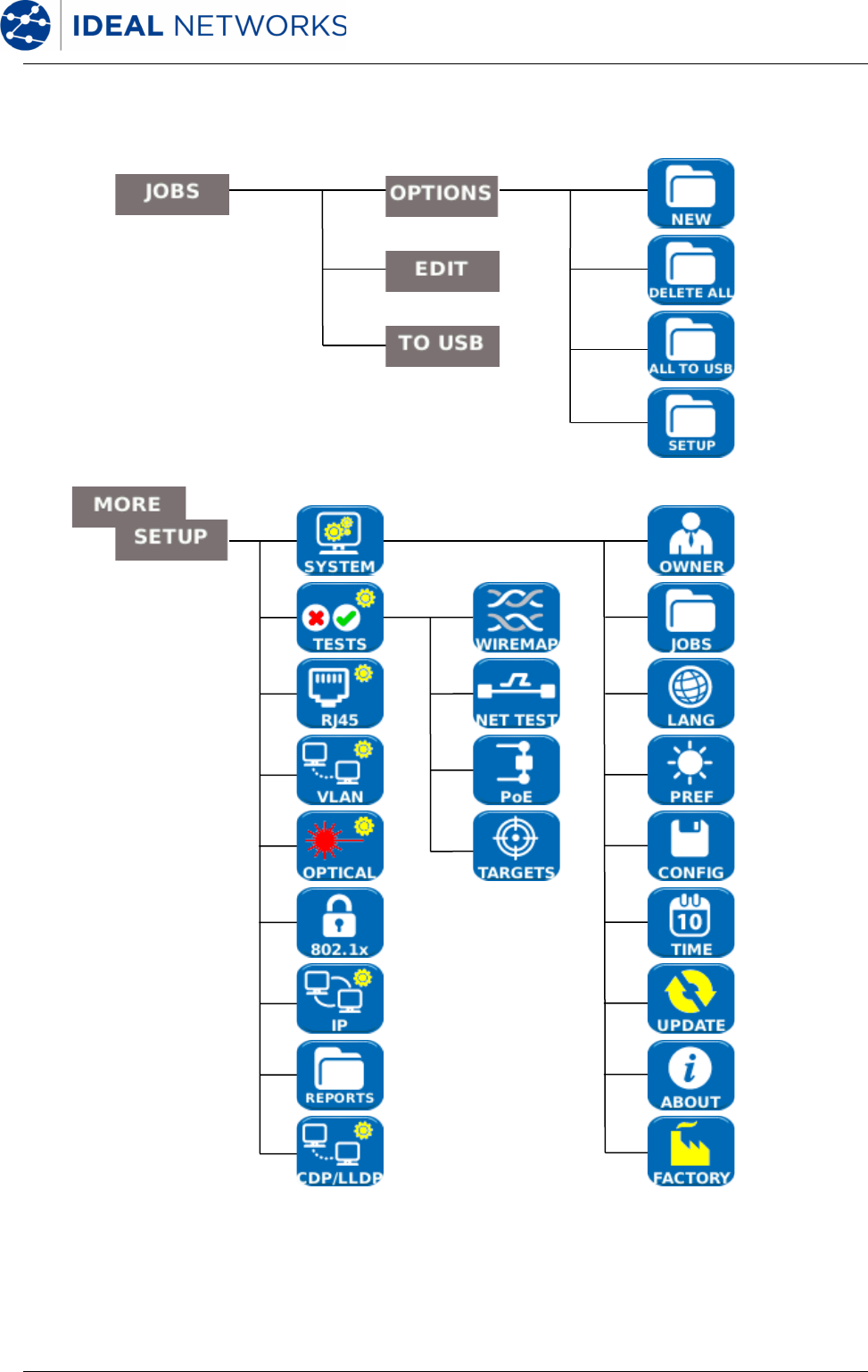
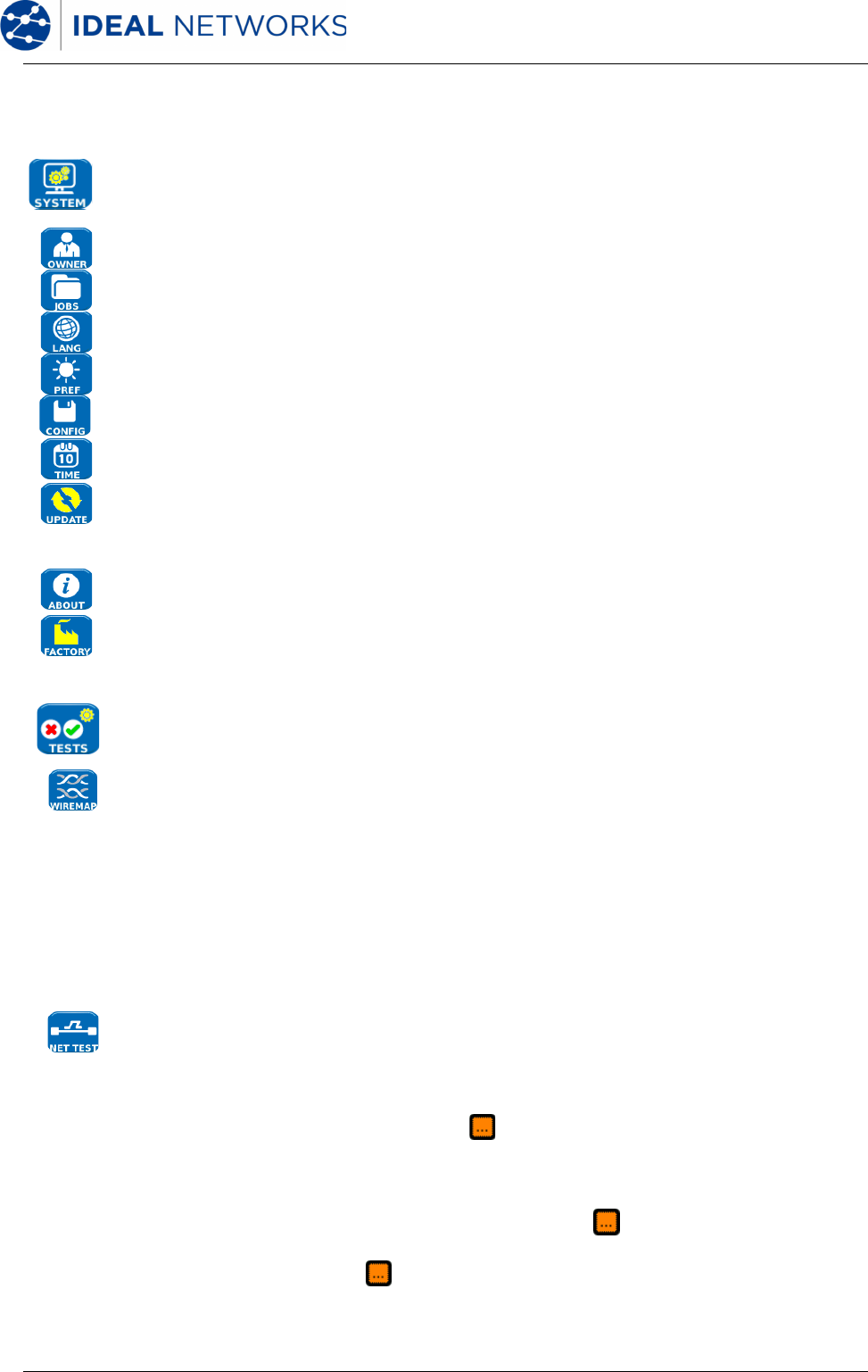
Menu Maps.......................................................................................................................................................................15
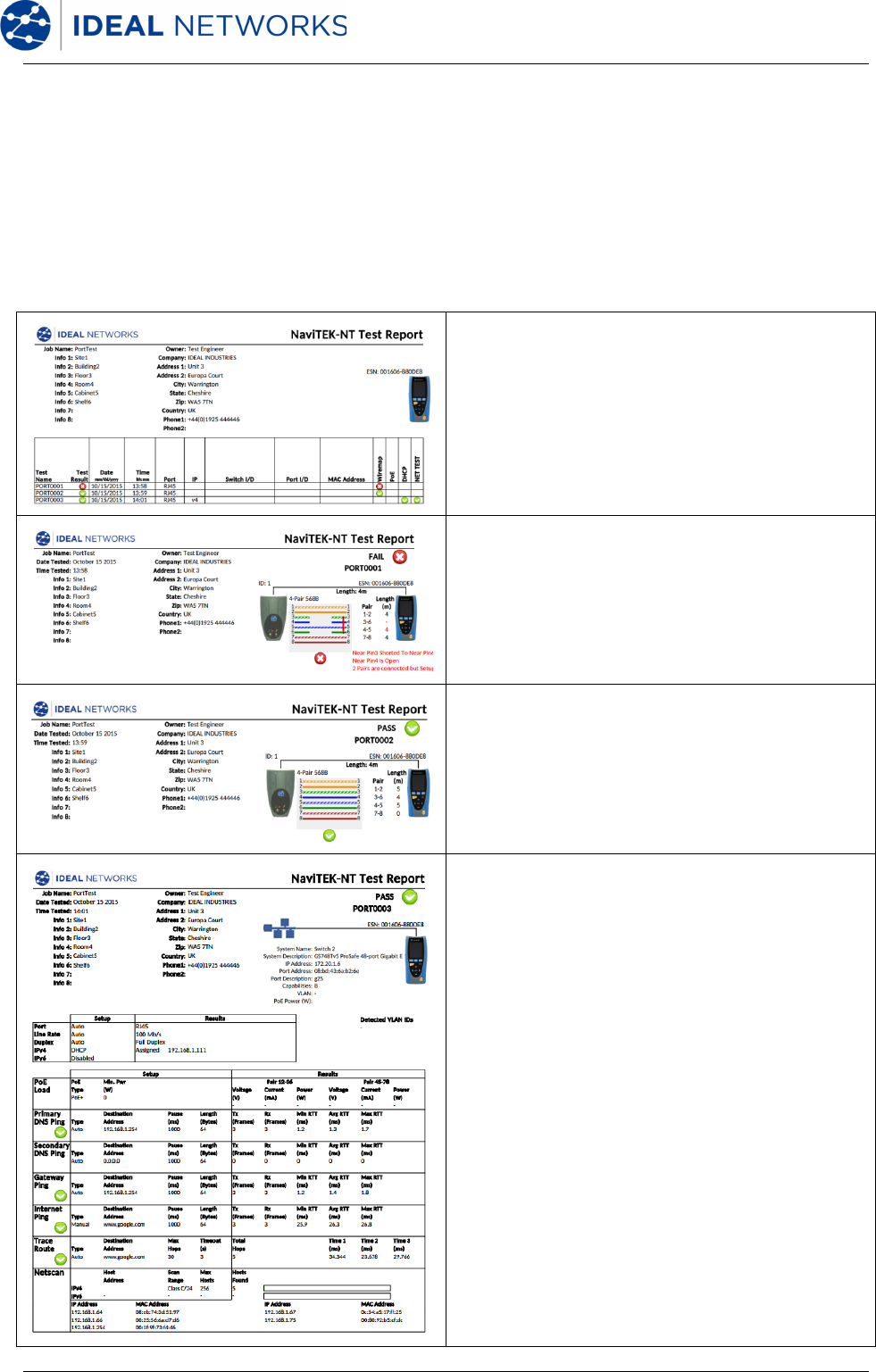
Generating and Uploading Reports.....................................................................................................................20
Specifications - NaviTEK NT Pro...........................................................................................................................22
Glossary, abbreviations and acronyms...............................................................................................................33
Introduction
NaviTEK NT is a network tester for troubleshooting and maintenance of active and passive
copper and fibernetworks. It performs a range of tests to determine as much information as
possible about the network and port to which it is connected.
The principleof operation of NaviTEK NT is that it automatically configures itself to match the
characteristics of the connected port, whether it is an un-terminated cable, a live copper
switch port or a live fiber switch port, and runs tests appropriate to that configuration.These
tests are designed to give information about the port, such as the switch MAC address and
identification, as well as to confirm that the port has been properly configured and is capable
of reaching a number of strategic targets in the localnetwork and the Internet. The user may
customize the tests if required.
Because the suite of tests runs and saves the results automatically, it is a simple task for the
user to move from port to port, fully testing and saving the results from each one. All that is
required is to plug the tester into the port socket and press the Autotestbutton.
Onceall oftherequirednetwork ports have been tested, the saved reportscan be uploaded
either using a USB memory key to a PC or via Wi-Fi to a Smartphone, for transfer to client
databases or to colleagues for further analysis.
This manual describes NaviTEK NTPro, and all references to "NaviTEK NT" shall be taken to
mean NaviTEK NT Pro. NaviTEK NT Pro includes provision for testing optical fiber networks as
wellas copper-based Ethernet networks, and 802.1x security log-in.
N
aviTEK NT Plus includes provision for testing copper-based Ethernet networks onlyand no
802.1x support.
Thebasic version of NaviTEK NT is described in a separate user manual.
NaviTEK NT151844Iss 2
User GuidePage 4
Safety Information
When using NaviTEK NT, always take basic safety precautions to reduce the risk of fire,
electric shock and injury to persons. These include the following:
•When connecting to the port, special care must be taken as high voltages may be
present and there may be a danger of electrocution.
•Avoid using the tester during an electrical storm - there is a remote risk of electric
shock by lightning.
•Use only the mains electricity adaptor supplied with your NaviTEK NT.
DO NOT CONNECT ANY TELECOMMUNICATIO
NS NETWORK
TO ANY OF THE TESTER’S PORTS
Powerand Maintenance
NaviTEK NTcan be powered from:
•A rechargeable power module,
•Directly from power connected to the DC inlet built in to the power module.
•An optional non-rechargeable battery pack
Power Module Management
The power module must be fully charged
before you use it for the first time
A fully charged power module will support up to five hours of heavy, continuous use. For
maximum life of the power module it is recommended to discharge it fully and then recharge
it fully at least once a month. The power module is not user-serviceable. When it has reached
the end of its life, pleasecontact your local IDEAL representative for service.
Power Module Recharging
The power module can be fully recharged in three hours with the NaviTEK NTswitched ON or
OFF. To recharge the power module, connect the supplied power adaptor to the DC inlet.
For convenience the power module may be removed from, or left attached to, the unit for
charging. The Power LED next to the DC inlet glows green to show that the battery is being
charged, and flashes green to show that it is not being charged. The power module charge
state is indicated at FULL, 2/3, 1/3 and EMPTY by the graphical power meter shown in the
display’s information bar at the top of its LCD display.
Switching ON and OFF
To switch ON the tester, press the ON/OFF button. A splash screen showing the IDEAL logo
and model identity is shown on the display. The home screen is then shown on the displayand
NaviTEK NTautomatically searches for a network to test.
To switch OFF, press and hold the Power button for approximately 1/2 second, a shutdown
message is displayed on the screen. The currently storedsetup is saved. If the unit does not
switch OFF within five secondsof pressing the Power button, please see Master Reset.
Always switch OFF the unit before removing the power module.
Caution
Do NOT remove the power module when the testeris switched on.
NaviTEK NT151844Iss 2
User GuidePage 5
Power Saving
Power saving preferences are selected from SETUP / SYSTEM/ PREF. Auto Off can be
Disabled (unit remains ON indefinitely), or set to switch the unit OFF after three, 10 or 30
minutes of inactivity. The backlight can be set to Always On, or to dim to 50% brightness
after three minutes of inactivity. Note that when mains power is connected the display is
always on full brightness and the unit remains ON indefinitely.
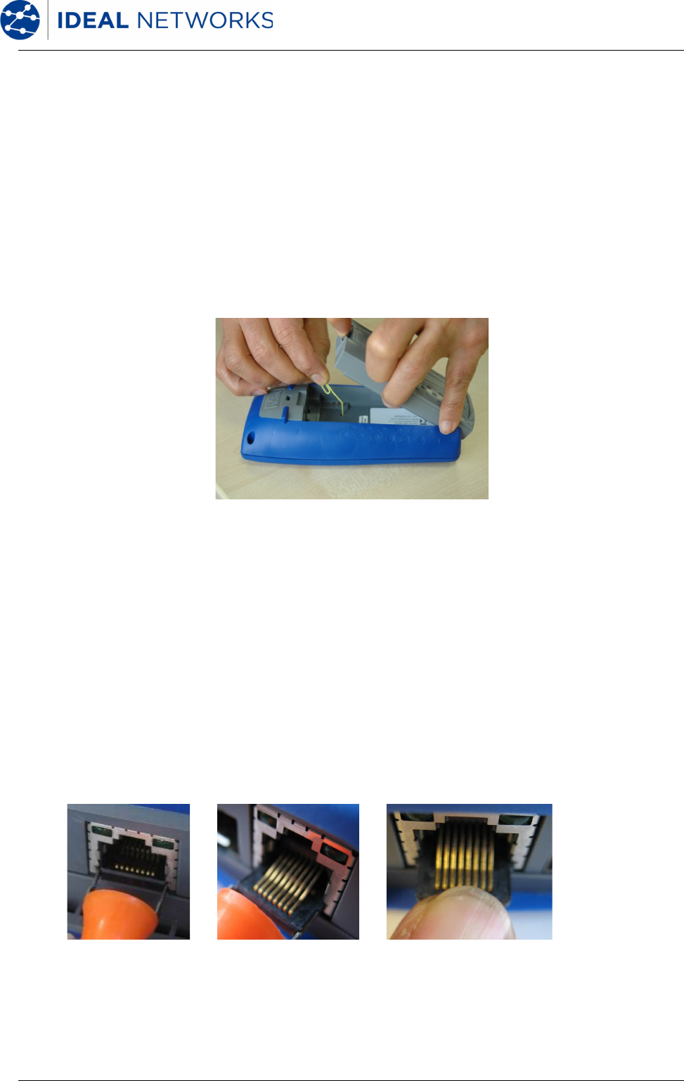
Master Reset
In the unlikely event of a system lock-up which prevents the unit from being switched OFF, it
may be necessary to perform a master reset. This will not delete any stored data.
1.Remove the power module to access a small aperture in the NaviTEK NT.
2.Insert a paper clip into the reset hole and press the internal reset switch.
3.Replace the power module.
Replaceable insert – RJ-45 socket
To replace a damaged or worn RJ-45 socket insert proceed as follows:
Equipment required: Kit, IDEAL part number 150058 – includes Tool x1 and Replacement
Insert x10.
1. Switch the NaviTEK NToff.
2. Remove cables.
3. Carefully push the tool STRAIGHT into the socket. BE CAREFUL - DO NOT MOVE
THE TOOL VERTICALLY!
4. Keeping the tool STRAIGHT firmly pull the insert out from the socket.
5. Using fingers replace a new insert STRAIGHT into the socket and securein place
by firmly pushing
3.4.5.
NaviTEK NT151844Iss 2
User GuidePage 6
Tester Layout
USB socket
Used for uploading results and
for downloading user logo and
software updates
Display
Shows settings and results
Function buttonsF1~F3
Press to activate the function
shown in the screen area above
the button
Escape button
Press to go back to the previous
screen without saving changes
ENTER button
Press to select the currently
highlighted screen function, or
to confirm changes
DC Input
Used to connect the power
supply /charger
(12vDC 2.5A)
Rechargeable battery module
(Non-rechargeable backup
battery packs are also available)
Power button
Press to switch the tester
ON/OFF
Cable socket
RJ45 socketto connect the
tester to copper Ethernet cables
and networks
Ethernet LED
Indicates that Ethernet is
connected
Activity LED
Indicates Ethernet data activity
Cursor buttons
Press to change which screen
function or item is highlighted
WiFi Adapter
Connects to smartphone app
Charging Indicator LED:
●Charging
○Charging complete
(Flashing) Not charging
Autotest button
Press to search for a connected
network
Optical linkLED(Pro only)
Indicates that a Fiber networkis
connected
Optical activityLED(Pro only)
Indicates Fiber link data activity
Optical port (SFP) (Pro only)
Accepts SFP optical modules to
connect the tester to 1Gb/s Fiber
networks
NaviTEK NT151844Iss 2
User GuidePage 7
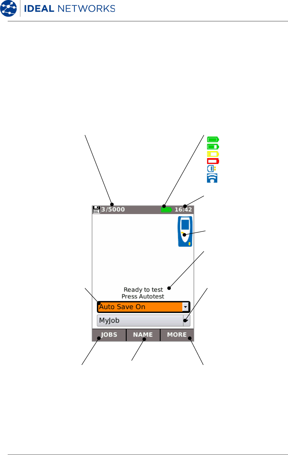
HOME Screen
•The HOME screen isdisplayed following start-up.
•To refresh the HOME screenandupdate the display of the current connection status,
press Autotest.
•To display more information aboutan item on the HOME screen, use the Cursor
buttons to move the orange highlight to the required itemon the screen, then press
ENTER.
•To return to the HOME screen from any other screen, press Escape repeatedly until the
HOME screen appears.
Memory Status
Shows the number of
results stored / total
capacity
Current time
TesterIcon
JOBS / SETUP
Press F1 (JOBS) to access
the JOBS menu
or following F3 (MORE)
press F1 (SETUP) to access
the SETUP menu (see
Menu Maps)
Auto Save Selection
Highlight the icon using the
cursor buttons and press
ENTERto select how results
should be saved
MORE
Press F3 (MORE) to
access the SETUP
menu using F1 (SETUP),
or to control the tone
generator using F2
(TONE) when a cable is
connected
Job Selection
Shows the currently
selected Job. Highlight the
icon using the cursor
buttons and press ENTER
to select which Job to save
results to
StatusIndications:
Battery full
Battery
2
/
3
full
Battery
1
/
3
full
Battery empty
Mains / on charge
Wi-Fi hot spot enabled
Notifications Area
Shows the current activity or
status of the tester
NAME
Press F2 (NAME) to edit the
name format of the next and
subsequent test resultsto
be saved
NaviTEK NT151844Iss 2
User GuidePage 8
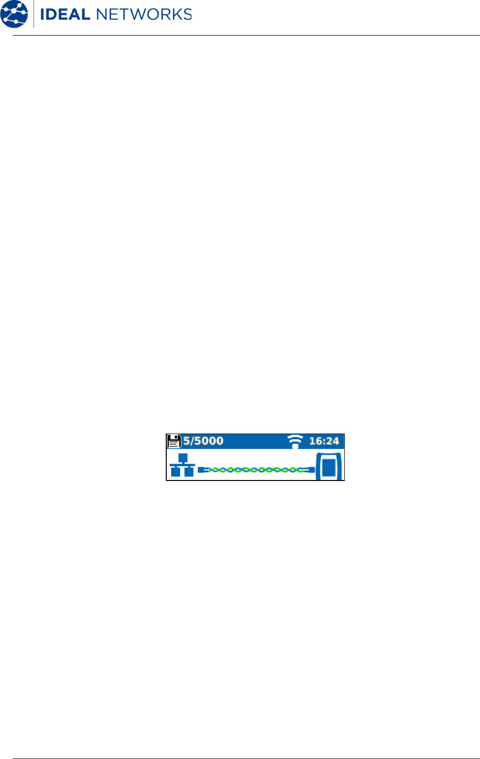
HOME Screen (with network cableconnected)
When the tester is connected to an un-terminatedcablegreater than ~3m (10ft) long,
Autotestdisplays agraphicalillustration of the cable, using the colour scheme set in
SETUP/TESTS/WIREMAP, showing the cablelength and any faultsby pair.
HOME Screen(with unknown network connected)
If the tester is accidentally connected to any type of network carrying voltages, for example a
telephone or ISDN network, the HOME screen displaysan alarm and details of the voltages. No
further testing is possible until the voltages have been removed.
Indication of network type
Indication of overall voltage
Indication of pin voltages:
1,2,3,4
5,6,7,8
Good Pair Indication
Overall Cable Length
Pair Lengths
Indicates the lengths of the
individual cable pairs
Short Circuit Pair Indication
Indicates a short circuit at the
far end of the cable
Open Circuit Pair Indication
Indicates an opencircuit at the
nearend of the cable
TONE
Press F3 (MORE), then F2
(TONE) to generate a tone on
the cable for tracing using a
compatible Tone Amplifier
Probe (available separately)
NaviTEK NT151844Iss 2
User GuidePage 9
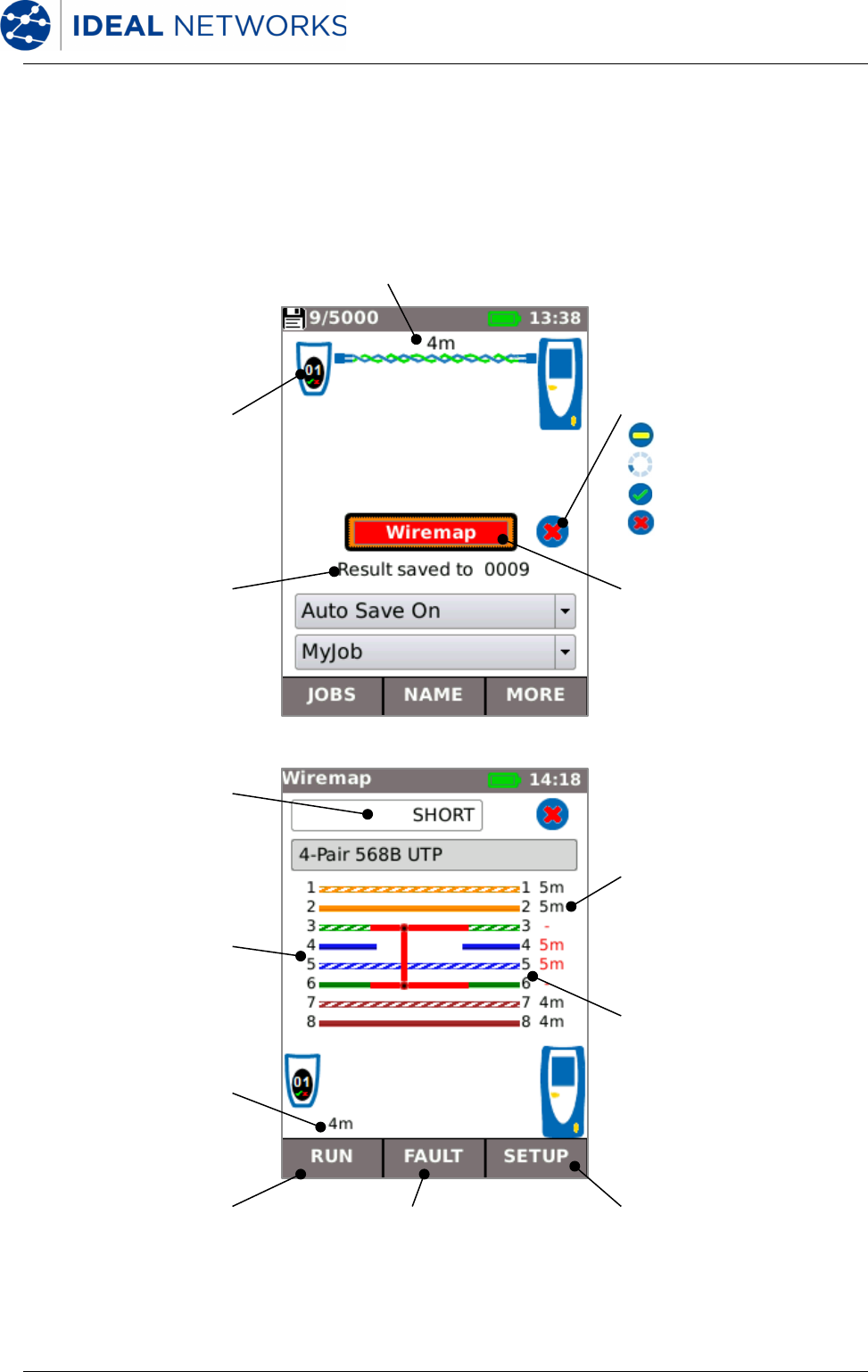
HOME Screen(with network cable connected to Active Remote)
When the tester is connected toa cablethat is terminated with an Active Remote, Autotest
runs an advanced Wiremap test that can detect split pairs and faults by pin. The HOME screen
displays a bar indicating the progress of the test. Select this bar and press ENTER to display
the Wiremap result screen. When the test is complete the result is saved(depending onthe
Auto Save setting).
Active Remote ID number
Overall Cable Length
Result saved indication
Indicates the name of the
last saved result
Wiremap test bar
Indicates progress and final
test result (Green = PASS, Red
= FAIL)
Highlight the bar using the
cursor keys then press ENTER
to display the Wiremap screen
Test Result
Pair Lengths
Indicates the lengths of the
individual cable pairs
Overall cable length
FAULT
Press F2(FAULT) to display a
list of faults found
Test Status:
Ready to test
Test in progress
Test Passed
Test Failed
RUN
Press F1 (RUN) to re- run the
Wiremap test without saving a
result
SETUP
Press F3(SETUP) to set the
Wiremap parameters according
to the type of cable tested
Active Remote pin numbers
Tester pin numbers
NaviTEK NT151844Iss 2
User GuidePage 10
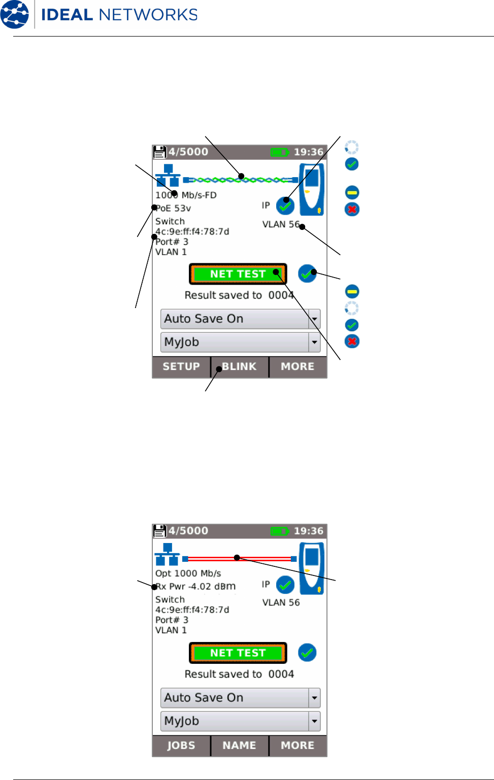
HOME Screen(with live copper network connected)
When the tester is connected to a live copper-based network, Autotest detects the partner
Ethernet device at the far end of the cable and automatically teststhe network connection
and displays information about it.
HOME Screen(with live fiber network connected - Pro only)
When the Pro tester is connected to a live1Gb/s fiber network, Autotest automaticallydetects
the partner Ethernet device at the far end of the fiber. (There is no need to selectcopper or
fiber mode manually.) With the exception of power, the tests and information shown on the
HOME screen are as for copper.
Port rate and duplex
Select then press ENTER to
display theStatistics, VLAN
and Port screens
Power over Ethernet status
Select then press ENTER to
displaythe PoE test screen
MAC and ID of switch port and
port VLAN setting
Select then press ENTER to
display details of the nearest
switch, reported by CDP, LLDP
or EDP(if supported by the
switch)
NET TEST test bar
Indicates progress and final test result
(Green = PASS, Red = FAIL)
Select then press ENTER to display the
NET TEST screen in detail
NET TESTStatus:
Ready to test
Test in progress
Test Passed
Test Failed
Tester IPStatus:
IP address assignmentin progress
Dynamic (DHCP) IP address
assigned
Static IP address assigned
IP address assignment failed
Select then press ENTER to display the
IP screen
Copper network connection
BLINK
Press F3 (MORE) then F2 (BLINK) to flash
the switch LED to assist in port identification
Tester VLAN ID
Received Optical Power
Select then press ENTER to
displaythe Optical screen
which gives details about the
SFP fitted and the transmitted
and received optical power
Fiber network connection
NaviTEK NT151844Iss 2
User GuidePage 11
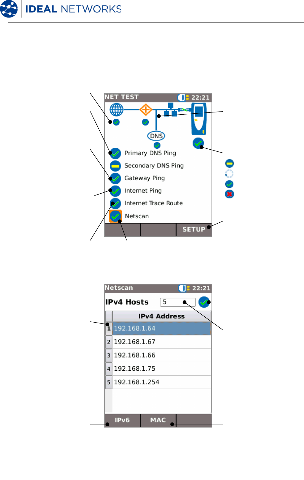
NET TEST and Netscan
When an Ethernet link is established, or Autotest is pressedwhile a link is up, a NET TEST is
run automatically. This test consists of aseries ofPing tests to multiple strategictargets in the
network, a Trace Route to a set destination, and a scan of all the hosts in the local network. To
display the NET TEST screen, select the test bar in the HOME screen and press ENTER.
Overall Test Result:
Not tested
Test in progress
Test Passed
Test Failed
Individual test result
Network map
Each tested network element is
shown by an icon that is
highlighted when the test result
is selected
DNS Ping results
The Secondary DNS is only
tested if the Primary DNS Ping
fails . Select and press ENTER
to display full details
Gateway Ping result
The Gateway is the route from
the local network to the
Internet. Select and press
ENTER to display full details
Internet Ping result
If this test passes, the tested
port has access to the Internet.
Select and press ENTER to
display full details
Trace Route result
Select and press ENTER to
display a list of all the hops
passed en route to the Internet
destination
Netscan result
Select and press ENTER to
display the Netscan screen
SETUP
Press F3 (SETUP) to access the
NET TEST setup screen
Host list
A list of all the hosts detected
in the local network
Netscan test result
IPv6 / IPv4
Press F1 to display IPv6 hosts
or IPv4 hosts
MAC / IP
Press F2 to display the MAC
address or IP address for each
host listed
Number of hosts found
NaviTEK NT151844Iss 2
User GuidePage 12
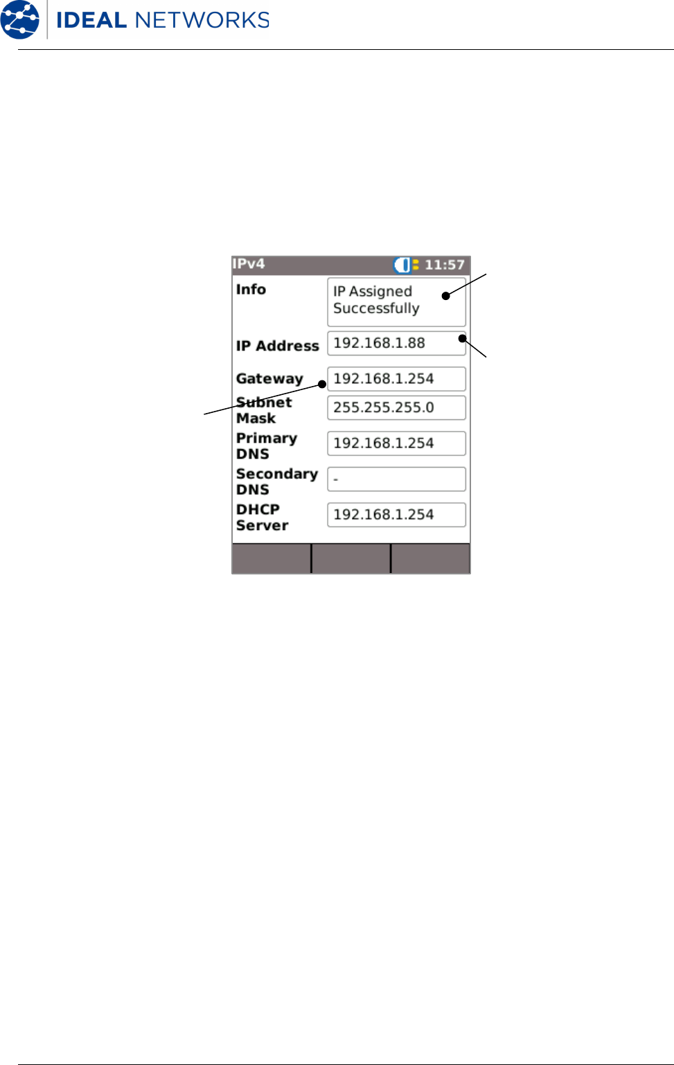
IP details screen
In the HOME screen, select the IP icon then press ENTER to display the IP screen.
This screen shows detail of the IP status and address of the tester and the IP addresses of the
network elements that are tested by the NET TEST.
Info
Indicates whether an IP address
has been assigned to the
tester, by DHCP or statically
IP Address
Tester IP address
Network IP addresses
IP addresses of the various
network elements
NaviTEK NT151844Iss 2
User GuidePage 13
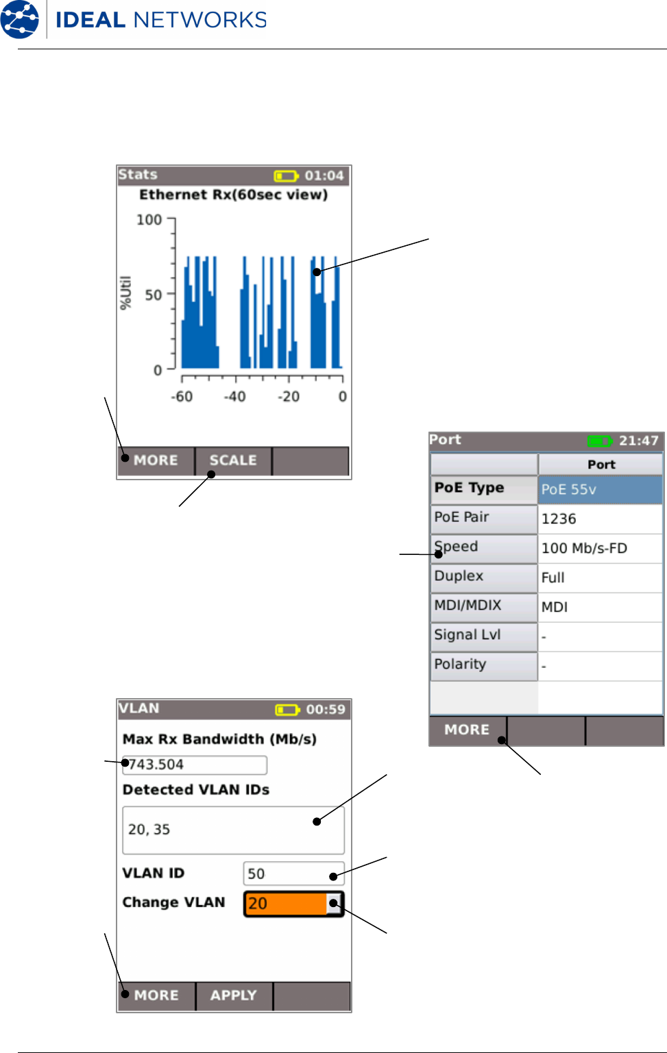
Statistics, Port and VLAN scan
When an Ethernet link is established, select the Port Rate / Duplex field in the HOME screen
and press ENTER to display detailed information abouttheconnection and the network.
Traffic graph
Shows the percentage of the
port rate utilised over time.
Connect the tester to a mirror
port or test port on the switch
to monitor traffic in a
particular network span
MORE
Press F1
(MORE) to
display the
next screen
SCALE
Press F2 (SCALE) to
adjust the time scale
MORE
Press F1
(MORE) to
display the
next screen
MORE
Press F1
(MORE) to
display the
next screen
Port data
Shows
information about
the connection
and the partner
port
VLANs
Lists the VLANs with
ID detected in the
network traffic
VLAN ID
The current VLAN
setting of the tester
Change VLAN
Select a VLAN from the list of
network VLANs detected. Press
ENTER to set the chosen VLAN as
the current tester VLAN setting,
then press F2 (APPLY)
Bandwidth
Shows the peak
traffic bandwidth
NaviTEK NT151844Iss 2
User GuidePage 14
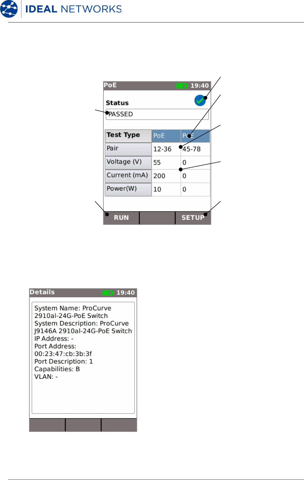
Power over Ethernet
When an Ethernetlink is established, Autotest automatically tests the port for the presence of
PoE and measures the available power by applying aminimumload. Select the PoE field in the
HOME screen and press ENTER to display the PoE screen.
Port Discovery information details
When an Ethernet link is established, Autotest automatically scans the partner port for Link
i have NaviTEK NT Plus and i want to export my jobs, but i cannot. When i plug a usb stick and press to usb ,it says please insert usb key ,while i have try with 3 different usb sticks. Also i buy a tp-link wifi usb adapter, but i can not install it . How i can do that? Can you please help and advise?
Libble takes abuse of its services very seriously. We're committed to dealing with such abuse according to the laws in your country of residence. When you submit a report, we'll investigate it and take the appropriate action. We'll get back to you only if we require additional details or have more information to share.
Product:
Forumrules
To achieve meaningful questions, we apply the following rules:
First, read the manual;
Check if your question has been asked previously;
Try to ask your question as clearly as possible;
Did you already try to solve the problem? Please mention this;
Is your problem solved by a visitor then let him/her know in this forum;
To give a response to a question or answer, do not use this form but click on the button 'reply to this question';
Your question will be posted here and emailed to our subscribers. Therefore, avoid filling in personal details.
Register
Register getting emails for Ideal Networks NaviTEK NT Plus at:
new questions and answers
new manuals
You will receive an email to register for one or both of the options.
Get your user manual by e-mail
Enter your email address to receive the manual of Ideal Networks NaviTEK NT Plus in the language / languages: English as an attachment in your email.
The manual is 6,8 mb in size.
You will receive the manual in your email within minutes. If you have not received an email, then probably have entered the wrong email address or your mailbox is too full. In addition, it may be that your ISP may have a maximum size for emails to receive.
Others manual(s) of Ideal Networks NaviTEK NT Plus
If you have not received an email with the manual within fifteen minutes, it may be that you have a entered a wrong email address or that your ISP has set a maximum size to receive email that is smaller than the size of the manual.
The email address you have provided is not correct.
Please check the email address and correct it.
Your question is posted on this page
Would you like to receive an email when new answers and questions are posted? Please enter your email address.