v
DOC ........................................................................................... i
IN CASE OF EMERGENCY ..................................................... ii
RECOMMENDATION ............................................................... ii
FOREWORD ............................................................................ iii
IMPORTANT ............................................................................ iii
EXPLICIT DEFINITIONS .......................................................... iii
FEATURES .............................................................................. iii
PRECAUTIONS ....................................................................... iv
TABLE OF CONTENTS ............................................................ v
1 OPERATING RULES ......................................................... 1
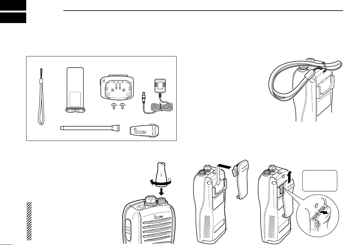
2 SUPPLIED ACCESSORIES AND ATTACHMENTS ....... 2–3
■ Supplied accessories ....................................................... 2
■ Attachments ..................................................................... 2
3 PANEL DESCRIPTION .................................................. 4–7
■ Front, top and side panels ............................................... 4
■ Function display .............................................................. 6
4 BASIC OPERATION .................................................... 8–13
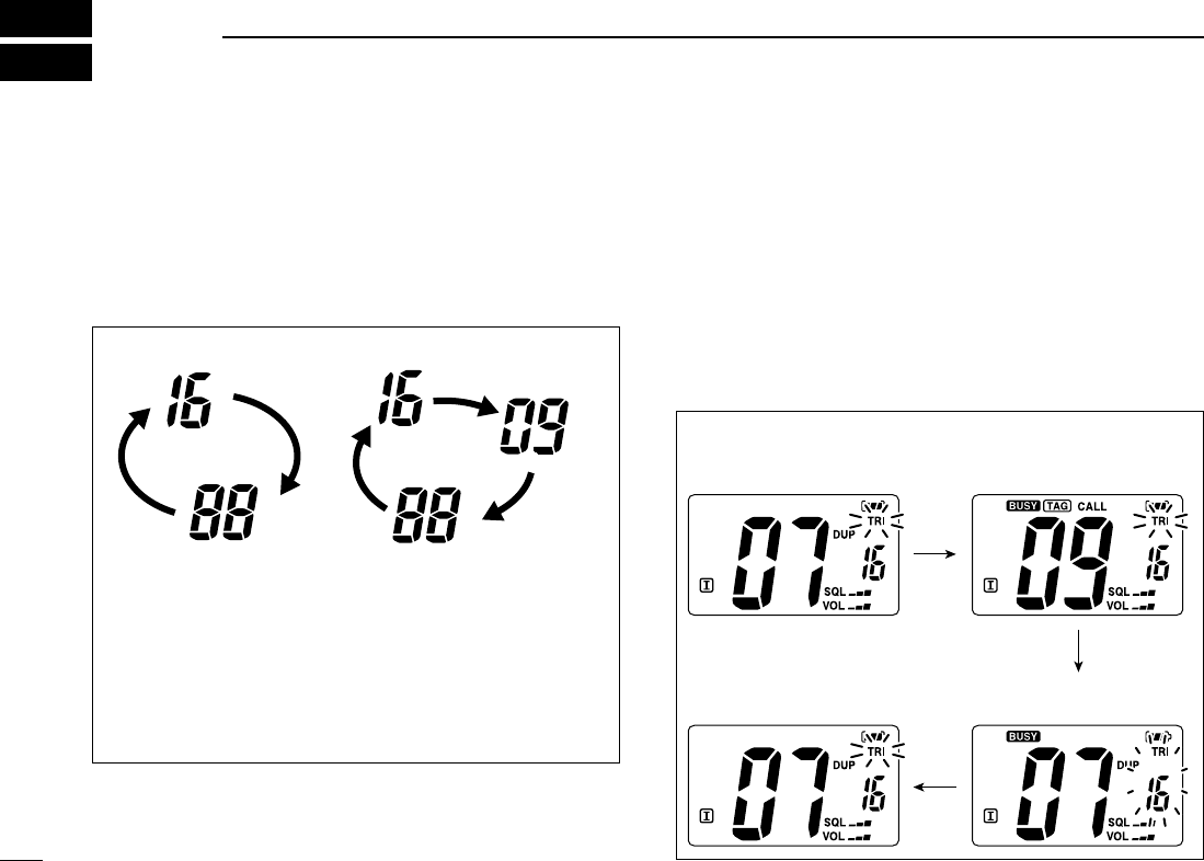
■ Channel selection ........................................................... 8
■ Receiving and transmitting ............................................ 10
■ Call channel programming ............................................ 11
■ Adjusting the volume level ............................................. 11
■ Volume mute function .................................................... 11
■ Adjusting the squelch level ........................................... 12
■ Lock function ................................................................. 12
■ Automatic backlighting .................................................. 12
■ Monitor function ............................................................ 13
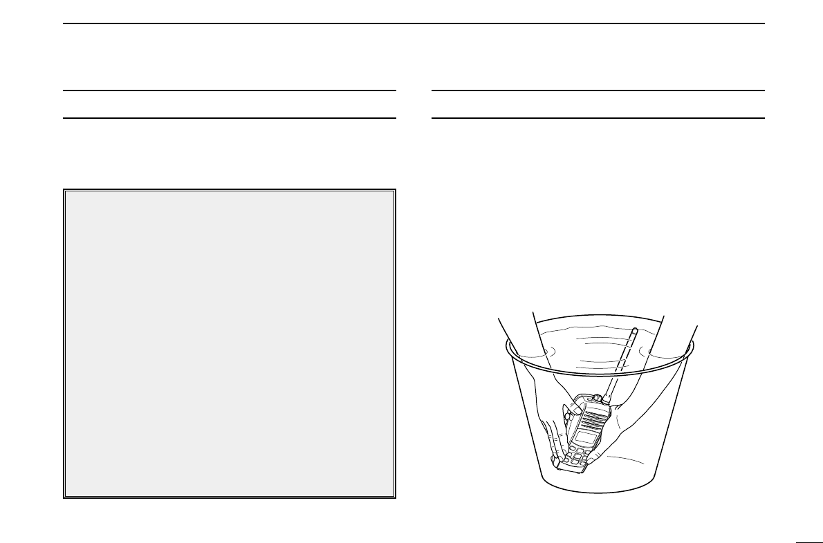
■ AquaQuake water draining function .............................. 13
5 SCAN OPERATION (Except Holland version) ........ 14–15
■ Scan types .................................................................... 14
■ Setting TAG channels ................................................... 15
■ Starting a scan .............................................................. 15
6 DUALWATCH/TRI-WATCH (Except Holland version) ... 16
■ Description .................................................................... 16
■ Operation ...................................................................... 16
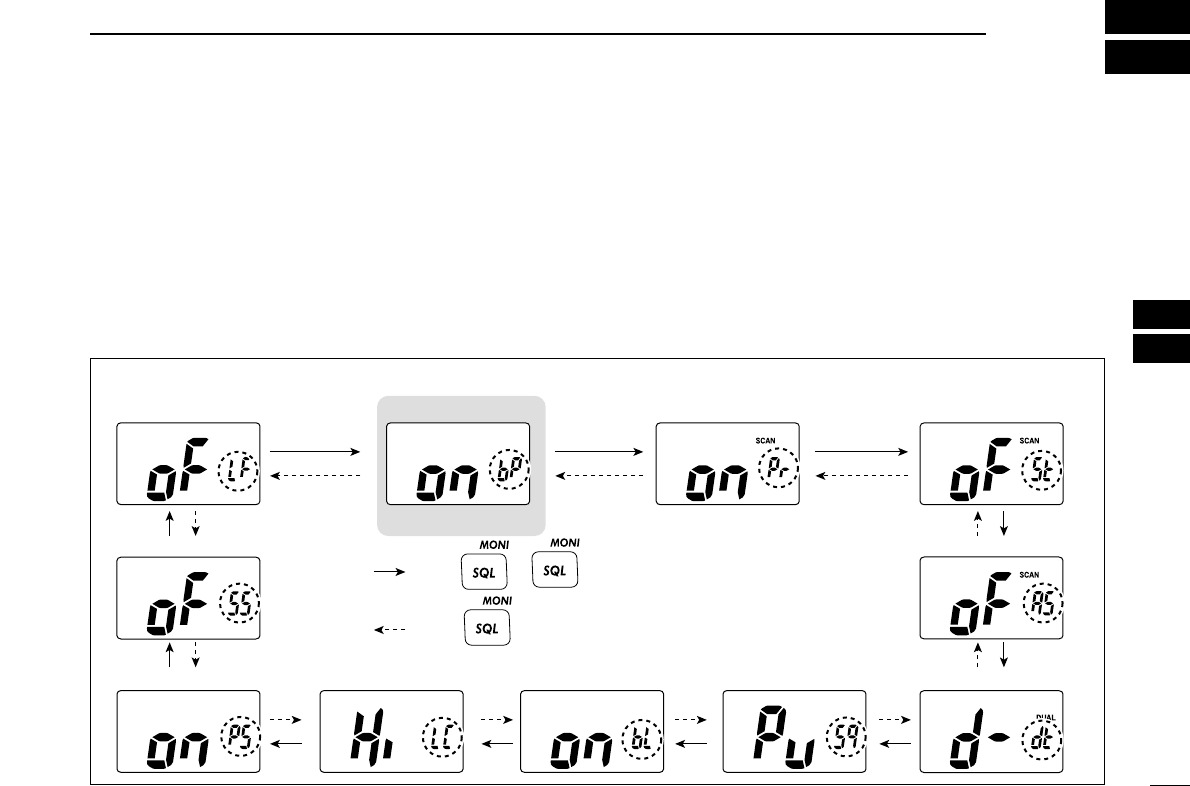
7 SET MODE ................................................................. 17–20
■ Set mode programming ................................................ 17
■ Set mode items ............................................................. 18
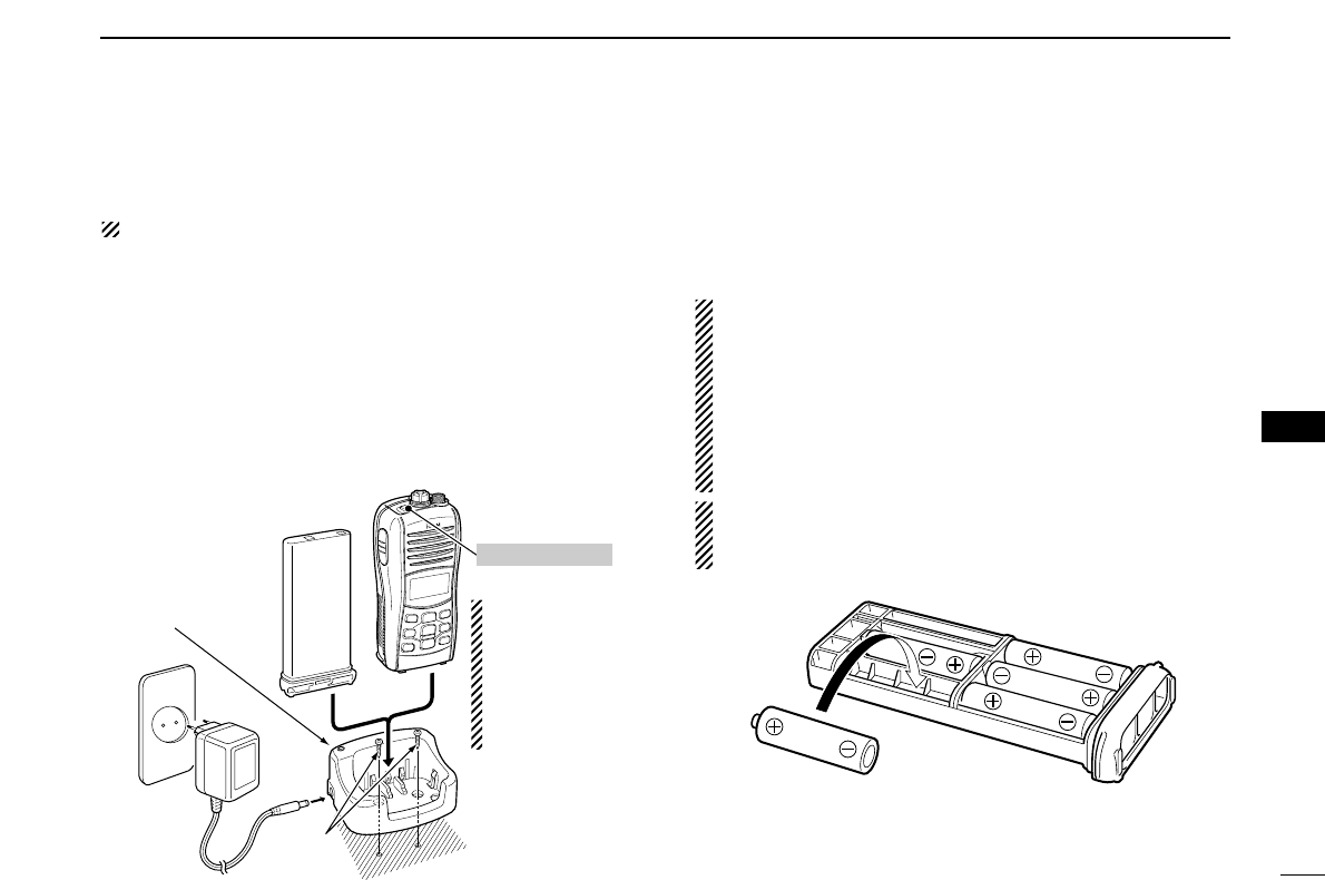
8 BATTERY CHARGING ............................................... 21–24
■ Battery caution .............................................................. 21
■ Supplied battery charger ............................................... 23
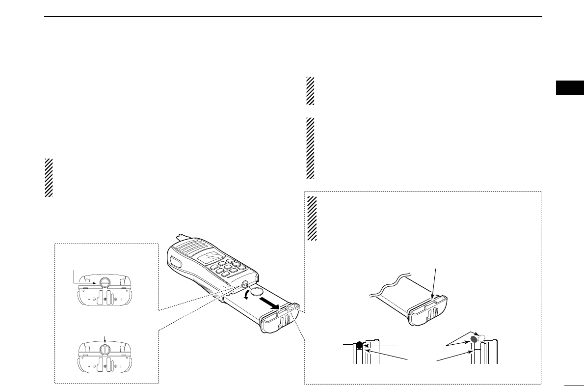
■ Optional battery case ..................................................... 23
■ Optional battery charger ............................................... 24
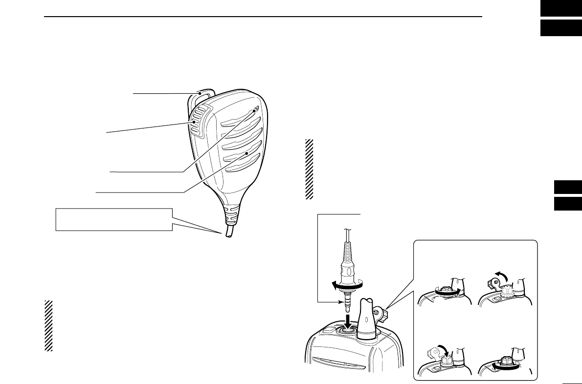
9 OPTIONAL SPEAKER-MICROPHONE ........................... 25
■ HM-165 descriptions ..................................................... 25
■ Attachment .................................................................... 25
10 TROUBLESHOOTING ..................................................... 26
11 VHF MARINE CHANNEL LIST ........................................ 27
12 SPECIFICATIONS............................................................. 28
13 OPTIONS .......................................................................... 29
TABLE OF CONTENTS