12304
154
Zoom out
Zoom in
Previous page
1/166
Next page
HF/VHF/UHF
ALL MODE TRANSCEIVER
i7000
INSTRUCTION MANUAL
i-1
IMPORTANT
READ THIS INSTRUCTION MANUAL
CAREFULLY before attempting to operate the
transceiver.
SAVE THIS INSTRUCTION MANUAL. This
manual contains important safety and operating in-
structions for the IC-7000.
EXPLICIT DEFINITIONS
WORD DEFINITION
RR
WARNING
Personal injury, fire hazard or electric
shock may occur.
CAUTION Equipment damage may occur.
NOTE
If disregarded, inconvenience only. No
risk or personal injury, fire or electric
shock.
We understand that you have a choice of many differ-
ent radios in the market place. We want to take a cou-
ple of moments of your time to thank you for making
the IC-7000 your radio of choice, and hope you agree
with Icom’s philosophy of “technology first.” Many
hours of research and development went into the de-
sign of your IC-7000.
D
FEATURES
IF DSP features
All mode capability covering 160–2 m and
70 cm (depending on version)
Compact with detachable front panel
±0.5 ppm of high frequency stability
Baudot RTTY demodulator
Simple band scope function
Selectable SSB transmission passband
width (For both higher and lower pass fre-
quency)
Standard voice synthesizer/voice recorder
The transceiver comes with the following acces-
sories.
Qty.
q Hand microphone (HM-151) ........................ 1
w DC power cable* (OPC-1457) ..................... 1
or (OPC-1457R) ............... 1
e Spare fuse (ATC 5 A) ................................... 1
r Spare fuse (ATC 30 A) ................................. 2
t ACC cable......................................................1
y 3.5 (d) mm plug..............................................1
u 6.5 (d) mm Electronic keyer plug ...................1
i Microphone hanger........................................1
o Ferrite bead**.................................................1
* Depending on versions.
**Not supplied with non-European versions.
q
e
t
w
w
yu
r
i
o
For European versions
(see p. 19 for installation details)
FOREWORD SUPPLIED ACCESSORIES
Icom, Icom Inc. and the logo are registered trademarks
of Icom Incorporated (Japan) in the United States, the United
Kingdom, Germany, France, Spain, Russia and/or other
countries.
Spurious signals may be received near the following fre-
quencies. These are created in the internal circuit and does
not indicate a transceiver malfunction:
52.76497 MHz,
443.03535 MHz
THIS P
THIS P
AGE
AGE
OPEN
OPEN
i-2
SPCH
/LOCK
TUNER
/CALL
XFC
V/M
F-1
F-2
FIL
MODE
GENE
MW
123
456
789
.
0
CE
F-INP
ENT
1.8 3.5 7
10 14 18
21 24 28
50 144 430
Mic element
q
e
w
o
!7!8!9@0@2@3@4 @1
t
r
yu !2
!5
!6
!1!0i
!3
!4
z
c
v
b
n
m
,
.
⁄0
⁄2
⁄3
⁄1
x
Front panel
HM-151
The front panel and HM-151’s panel
descriptions are descrived on pages
1 to 4, and on page 9, respectively
(see the Chapter 1 ‘PANEL DE-
SCRIPTION’ for more details).
ILLUSTRATIONS
i-3
Front panel
q AF GAIN CONTROL [AF] (inner control; p. 33)
w RF GAIN CONTROL/SQUELCH CONTROL
[RF/SQL] (outer control; p. 35)
e POWER KEY [PWR] (p. 25)
r FRONT PANEL LATCH (p. 16)
t PASSBAND TUNING/M-ch/RIT CONTROLS
[PBT/M-ch/RIT] (pgs. 73, 77, 86, 100, 104)
y TWIN PBT (M-ch/RIT) INDICATOR
(pgs. 73, 77, 86, 100)
u MENU/GROUP KEYS [MENU/GRP] (p. 151)
i TUNER/CALL KEY [TUNER/CALL]
(pgs. 100, 114)
o MULTI-FUNCTION KEYS [F1]/[F2]/[F3]/[F4]
(pgs. 5–8, 151)
!0 MANUAL NOTCH KEY [MNF/ADJ] (p. 81)
!1 AUTO NOTCH/VOICE RECORDER KEY
[ANF/
REC] (pgs. 80, 93)
!2 SPCH/LOCK KEY [SPCH/LOCK] (pgs. 34, 37)
!3 MICROPHONE CONNECTOR (p. 10)
!4
UP/DOWN (BAND) KEYS
[Y(
BAND
)]/[
ZZ
(
BAND
)]
!5 MAIN DIAL TENSION LATCH
!6 HEADPHONE JACK [PHONES] (p. 18)
!7 MAIN DIAL [DIAL]
!8 RECEIVE/TRANSMIT INDICATORS [RX]/[TX]
!9 TUNING STEP KEY [TS] (pgs. 30–32)
@0 NOISE BLANKER KEY [NB/ADJ] (p. 78)
@1 NOISE REDUCTION KEY [NR/LEV] (p. 79)
@2 FUNCTION DISPLAY (p. 13)
@3 PRE AMP/ATTENUATOR KEY [P.AMP/ATT]
(p. 72)
@4 MODE KEY [MODE] (p. 34)
Microphone (HM-151)
z SPCH/LOCK KEY [SPCH/LOCK] (p. 34, 37)
x PTT SWITCH [PTT] (p. 37)
c UP/DOWN SWITCHES [
YY
]/[
ZZ
]
v TRANSMIT INDICATOR (p. 37)
b KEYPAD (pgs. 28, 29)
n FILTER SELECTION [FIL] (p. 75)
m MODE KEY [MODE] (p. 34)
, POWER INDICATOR
. PROGRAMMABLE FUNCTION KEYS [F-1]/[F-2]
⁄0 MEMORY WRITE [MW] (pgs. 101, 102)
⁄1 VFO/MEMORY SELECTION [V/M]
(pgs. 27, 100, 107)
⁄2 TRANSMIT FREQUENCY CHECK [XFC]
(pgs. 65, 89)
⁄3 TUNER/CALL KEY [TUNER/CALL]
(pgs. 100, 114)
ii
R WARNING RF EXPOSURE! This device emits
Radio Frequency (RF) energy. Extreme caution should be
observed when operating this device. If you have any
questions regarding RF exposure and safety standards
please refer to the Federal Communications Commission
Office of Engineering and Technology’s report on Evalu-
ating Compliance with FCC Guidelines for Human Radio
Frequency Electromagnetic Fields (OET Bulletin 65).
R WARNING HIGH VOLTAGE! NEVER touch an
antenna or internal antenna connector during transmis-
sion. This may result in an electrical shock or burn.
R WARNING! NEVER operate the transceiver while
driving a vehicle. Safe driving requires your full atten-
tion—anything less may result in an accident.
R NEVER apply AC power to the [DC13.8V] socket on
the transceiver rear panel. This could cause a fire or dam-
age the transceiver.
R NEVER apply more than 16 V DC, such as a 24 V
battery, to the [DC13.8V] socket on the transceiver rear
panel. This could cause a fire or damage the transceiver.
R NEVER let metal, wire or other objects touch any in-
ternal part or connectors on the rear panel of the trans-
ceiver. This may result in an electric shock or this could
cause a fire or damege the transceiver.
R NEVER connect or use the supplied HM-151 (micro-
phone) with other transceiver. This could cause damage
to the transceiver. The HM-151 is designed for use with
the IC-7000 ONLY.
NEVER expose the transceiver to rain, snow or any liq-
uids.
AVOID using or placing the transceiver in areas with tem-
peratures below –10°C (+14°F) or above +60°C (+140°F).
Be aware that temperatures on a vehicle’s dashboard can
exceed +80°C (+176°F), resulting in permanent damage
to the transceiver if left there for extended periods.
AVOID placing the transceiver in excessively dusty envi-
ronments or in direct sunlight.
AVOID placing the transceiver against walls or putting
anything on top of the transceiver. This will obstruct heat
dissipation.
Place unit in a secure place to avoid inadvertent use by
children.
During mobile operation, NEVER place the transceiver
where air bag deployment may be obstructed.
During mobile operation, DO NOT place the transceiver
where hot or cold air blows directly onto it.
During mobile operation, DO NOT operate the transceiver
without running the vehicle’s engine. When the trans-
ceivers power is ON and your vehicle’s engine is OFF,
the vehicle’s battery will soon become exhausted.
Make sure the transceiver power is OFF before starting
the vehicle engine. This will avoid possible damage to the
transceiver by ignition voltage spikes.
During maritime mobile operation, keep the transceiver
and microphone as far away as possible from the mag-
netic navigation compass to prevent erroneous indica-
tions.
BE CAREFUL! The rear panel will become hot when op-
erating the transceiver continuously for long periods.
BE CAREFUL! If a linear amplifier is connected, set the
transceivers RF output power to less than the linear am-
plifiers maximum input level, otherwise, the linear ampli-
fier will be damaged.
Use Icom microphones only (supplied or optional). Other
manufacturers microphones have different pin assign-
ments, and connection to the IC-7000 may damage the
transceiver.
For U.S.A. only
Caution: Changes or modifications to this transceiver,
not expressly approved by Icom Inc., could void your
authority to operate this transceiver under FCC regu-
lations.
PRECAUTIONS
iii
IMPORTANT …………………………………………i-1
FOREWORD ………………………………………… i-1
EXPLICIT DEFINITIONS …………………………… i-1
SUPPLIED ACCESSORIES…………………………i-1
ILLUSTRATIONS ……………………………………i-2
Front panel ……………………………………… i-3
Microphone (HM-151) ………………………… i-3
PRECAUTIONS ………………………………………ii
TABLE OF CONTENTS …………………………… iii
1PANEL DESCRIPTION …………………1–14
Front panel ………………………………………… 1
Multi-function keys ……………………………… 5
D Menu M-1 functions …………………………… 5
D Menu M-2 functions …………………………… 5
D Menu M-3 functions …………………………… 5
D Menu S-1 functions …………………………… 7
D Menu S-2 functions …………………………… 7
D Menu S-3 functions …………………………… 8
D Menu G-1 (Scope) functions ………………… 8
Microphone (HM-151) …………………………… 9
D Microphone connector ……………………… 10
Rear panel ……………………………………… 11
D DATA socket…………………………………… 12
D ACC socket …………………………………… 12
Function display ………………………………… 13
2 INSTALLATION AND CONNECTIONS 15–24
Unpacking ……………………………………… 15
Selecting a location……………………………… 15
Grounding………………………………………… 15
Antennaconnection……………………………… 15
Installation ……………………………………… 16
D Single body mounting………………………… 16
D Stand…………………………………………… 16
D Front panel separation ……………………… 16
D Front panel mounting ………………………… 16
Required connections…………………………… 17
Advanced connections ………………………… 18
Power supply connections……………………… 19
Connecting a DC power supply ……………… 19
Battery connections …………………………… 19
External antenna tuners………………………… 20
Linear amplifier connections …………………… 21
Connections for CW …………………………… 22
Connections for RTTY ………………………… 23
D Connections for RTTY (FSK)………………… 23
D Connections for RTTY (AFSK) ……………… 23
Connections for packet, SSTV or PSK31 …… 24
D When connecting to [DATA] socket ………… 24
D When connecting to [ACC] socket ………… 24
D When connecting to [MIC] connector ……… 24
3 BASIC OPERATION ……………………25–38
When first applying power (CPU resetting)…… 25
D Menu resetting (M-1)………………………… 25
Initial settings …………………………………… 25
VFO description ………………………………… 26
D Differences between VFO and
memory mode ………………………………… 26
VFO operation …………………………………… 27
D Selecting VFO A/VFO B ……………………… 27
D VFO equalization……………………………… 27
Selecting VFO/memory mode ………………… 27
Selecting an operating band …………………… 28
D Using the band stacking registers…………… 28
Frequency setting ……………………………… 29
D Tuning with the main dial …………………… 29
D Direct frequency entry
with the microphone’s keypad ……………… 29
D Programmable tuning step…………………… 30
D Selecting “kHz” step ………………………… 30
D Selecting 1 Hz or 10 Hz step
(SSB/CW/RTTY only) ………………………… 31
D 1 MHz quick tuning step
(FM/WFM/AM only)…………………………… 31
D
1
4
tuning function (CW/RTTY only) ………… 32
D Auto tuning step function …………………… 33
D Band edge warning beep …………………… 33
Volume setting…………………………………… 33
Operating mode selection ……………………… 34
Voice synthesizer function……………………… 34
Squelch and receive (RF) sensitivity ………… 35
Meter function …………………………………… 36
D Multi-function meter…………………………… 36
Lock functions …………………………………… 37
D Dial lock function ……………………………… 37
D Microphone lock function …………………… 37
Basic transmit operation ……………………… 37
D Transmitting …………………………………… 37
D Setting output power ………………………… 38
D Setting microphone gain……………………… 38
4 RECEIVE AND TRANSMIT ……………39–69
Operating SSB…………………………………… 39
D Convenient functions for receive …………… 39
D Convenient functions for transmit…………… 40
D About 5 MHz band operation
(USA version only) …………………………… 40
Operating CW …………………………………… 41
D Convenient functions for receive …………… 42
D Convenient functions for transmit…………… 42
D CW reverse mode …………………………… 43
D CW side tone function………………………… 43
D CW pitch control ……………………………… 44
Electronic CW keyer …………………………… 45
D Memory keyer send menu …………………… 46
D Editing a keyer memory ……………………… 47
D Contest number set mode …………………… 48
1 Number Style ……………………………… 48
2 Count UP Trigger …………………………… 48
3 Present Number …………………………… 48
D Keyer set mode ……………………………… 49
1 Keyer Repeat Time ………………………… 49
2 Dot/Dash Ratio……………………………… 49
3 Rise Time …………………………………… 50
TABLE OF CONTENTS
iv
4 Paddle Polarity ……………………………… 50
5 Keyer Type ………………………………… 50
6 MIC U/D Keyer (HM-103) ………………… 50
D Paddle operation from [MIC] connector …… 50
Operating RTTY (FSK) ………………………… 51
D Convenient functions for receive …………… 52
D RTTY reverse mode ………………………… 53
D Twin peak filter………………………………… 53
D Functions for the RTTY decoder indication… 54
D Setting the decoder threshold level ………… 54
D RTTY decode set mode ……………………… 55
1 RTTY Decode USOS ……………………… 55
2 RTTY Decode New Line Code …………… 55
D
Pre-setting for using RTTY terminal or TNC
…56
Operating AM …………………………………… 57
D Convenient functions for receive …………… 57
D Convenient functions for transmit…………… 58
Operating FM …………………………………… 59
D Convenient functions for receive …………… 59
D Convenient functions for transmit…………… 59
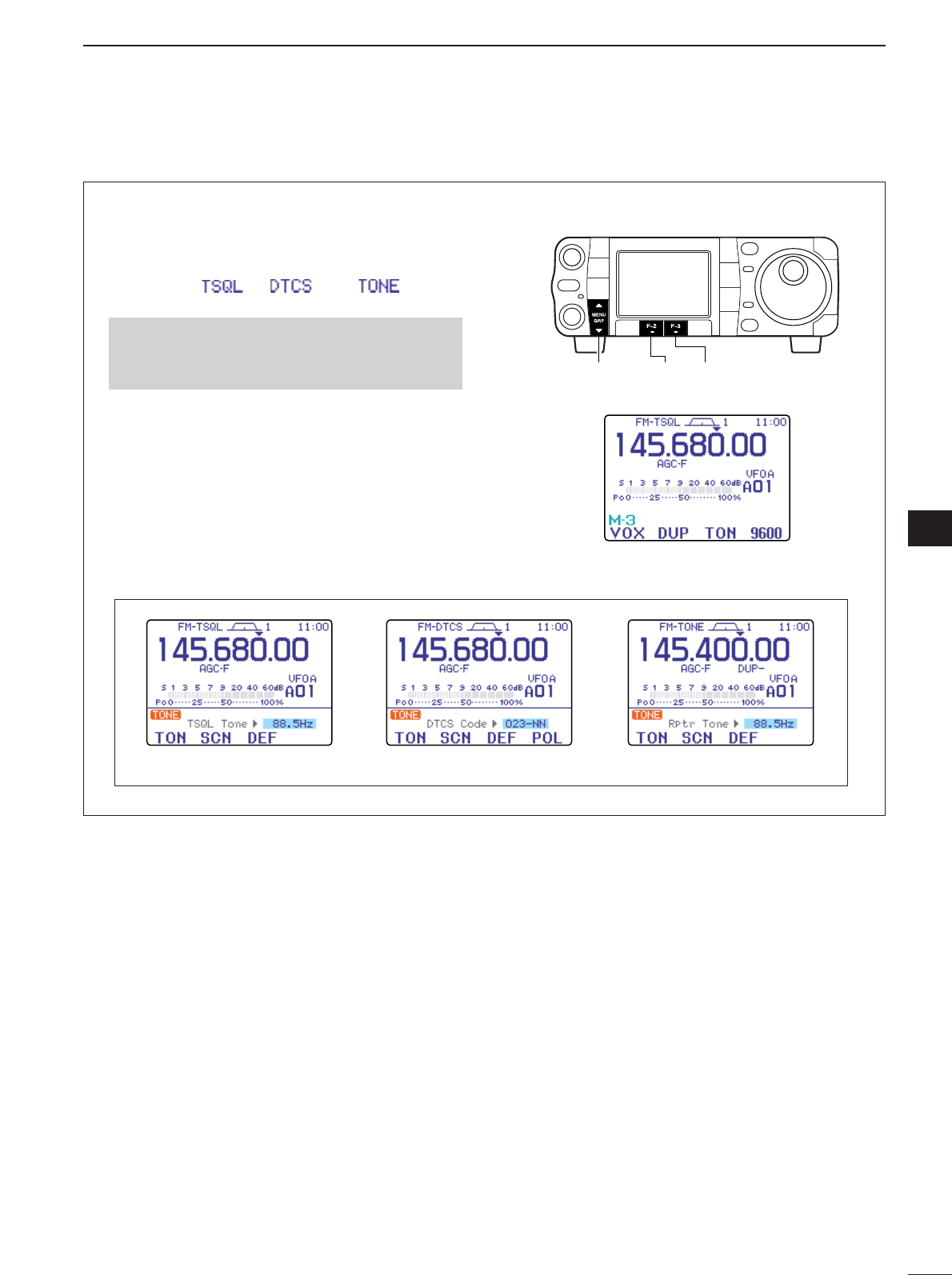
D Tone squelch operation ……………………… 60
D DTCS operation ……………………………… 61
D Tone scan operation ………………………… 62
Repeater operation……………………………… 63
D One-touch repeater function ………………… 63
D Repeater tone frequency …………………… 64
D Transmit frequency monitor check ………… 65
D Auto repeater function (USA version only) … 65
D Storing a non standard repeater …………… 66
1750 Hz tone burst ……………………………… 67
DTMF memory encoder………………………… 67
D DTMF send menu …………………………… 67
D Programming a DTMF code ………………… 68
D DTMF speed…………………………………… 68
5 FUNCTIONS FOR RECEIVE……………69–82
Simple band scope ……………………………… 69
D Fix mode ……………………………………… 70
D Center mode…………………………………… 71
D Scope set mode ……………………………… 71
1 Max Hold …………………………………… 72
2 Scope Size ………………………………… 72
3 FAST Sweep………………………………… 72
4 FAST Sweep Sound ……………………… 72
Preamp and attenuator ………………………… 72
RIT function ……………………………………… 73
AGC function …………………………………… 74
D AGC time constant selection………………… 74
D Setting the AGC time constant ……………… 74
IF filter selection ………………………………… 75
D IF filter selection ……………………………… 75
D Filter passband width setting
(SSB/CW/RTTY/AM only) …………………… 76
D IF filter shape (SSB/CW only) ……………… 76
Twin PBT operation …………………………… 77
Noise blanker …………………………………… 78
D Noise blanker set mode ……………………… 78
1 NB Level …………………………………… 78
2 NB Width …………………………………… 78
Noise reduction ………………………………… 79
D Noise reduction set mode …………………… 79
NR Level …………………………………… 79
Notch function …………………………………… 80
D Auto notch function …………………………… 80
D Manual notch function………………………… 81
D Manual notch filter set mode ………………… 81
Voice squelch control function ………………… 82
Meter peak hold function ……………………… 82
6 FUNCTIONS FOR TRANSMIT …………83–92
VOX function …………………………………… 83
D Adjusting the VOX function ………………… 83
D VOX set mode ………………………………… 84
1 VOX Gain …………………………………… 84
2 Anti-VOX …………………………………… 84
3 VOX Delay ………………………………… 84
Transmit filter width setting (SSB only) ……… 84
Break-in function ………………………………… 85
D Semi break-in operation……………………… 85
D Full break-in operation ……………………… 85
TX function …………………………………… 86
Monitor function ………………………………… 87
Speech compressor …………………………… 87
D Compression level setting …………………… 88
COMP Level ……………………………… 88
Split frequency operation ……………………… 89
Quick split function ……………………………… 90
D Split offset frequency setting ………………… 91
D Quick split setting …………………………… 91
Measuring SWR ………………………………… 92
D Spot measurement …………………………… 92
D Plot measurement …………………………… 92
7 VOICE RECORDER FUNCTIONS ……93–99
Digital voice recorder …………………………… 93
Recording a received audio …………………… 93
D Basic recording ……………………………… 93
D One-touch voice recording…………………… 94
Playing the recorded contents ………………… 94
Erasing the recorded contents ………………… 95
Recording a message for transmit …………… 96
D Recording ……………………………………… 96
D Confirming/Erasing the recorded message… 96
Programming a memory name for transmit … 97
Sending a recorded message ………………… 98
D Transmit level setting ………………………… 98
Voice set mode ………………………………… 99
D Voice set mode ……………………………… 99
1 Auto Monitor ………………………………… 99
2 MIC Memo…………………………………… 99
8 MEMORY OPERATION ………………100–110
Memory channels ……………………………… 100
Memory channel selection …………………… 100
Memory programming ………………………… 101
D Programming in VFO mode………………… 101
D Programming in memory mode …………… 102
Memory channel list …………………………… 103
TABLE OF CONTENTS
1
2
3
4
5
6
7
8
9
10
11
12
13
14
15
16
17
18
19
20
21
v
D Selecting a memory channel
using the memory channel list……………… 103
D Setting a memory channel
as a select memory ………………………… 104
D Selecting a memory bank ………………… 104
D Memory names ……………………………… 105
Memory clearing ……………………………… 106
D Memory clearing
using the memory channel list……………… 106
Frequency transferring………………………… 107
D Transferring in VFO mode ………………… 107
D Transferring in memory mode……………… 108
Memo pads …………………………………… 109
D Writing frequencies and operating modes
into memo pads……………………………… 109
D Calling up a frequency from a memo pad 110
9 SCAN OPERATION …………………111–113
Scan types ……………………………………… 111
Preparation……………………………………… 111
Programmed scan operation ………………… 112
Memory scan operation ……………………… 112
Select memory scan operation ……………… 113
Priority watch …………………………………… 113
10 ANTENNA TUNER OPERATION … 114–115
Optional AT-180
AUTOMATIC ANTENNA TUNER
operation………………………………………… 114
D Tuner operation ……………………………… 114
D Manual tuning………………………………… 114
Optional AH-4
AUTOMATIC ANTENNA TUNER
operation………………………………………… 115
D AH-4 operation ……………………………… 115
11 PACKET OPERATION …………………… 116
Packet operation ……………………………… 116
D Data socket…………………………………… 116
D Adjusting the data speed …………………… 116
D Adjusting the transmit signal output
from the TNC ………………………………… 116
12 CLOCK AND TIMERS ……………… 117–119
Time set mode ………………………………… 117
1 Year ………………………………………… 117
2 Date ………………………………………… 117
3 Time (Now) ………………………………… 117
4 CLOCK2 Function ………………………… 117
5 CLOCK2 Offset …………………………… 117
6 Auto Power OFF …………………………… 117
D Setting the current year …………………… 118
D Setting the current date …………………… 118
D Setting the current time …………………… 118
D Clock2 function activity……………………… 119
D Clock2 offset setting ………………………… 119
D Auto power OFF activity …………………… 119
13 SET MODE ………………………… 120–136
Set mode description ………………………… 120
Quick set mode ………………………………… 121
RF Power (all modes) ……………………… 121
MIC Gain (SSB/AM/FM modes)…………… 121
SSB TBW (WIDE) L (SSB mode) ………… 121
SSB TBW (WIDE) H (SSB mode) ………… 122
SSB TBW (MID) L (SSB mode) …………… 122
SSB TBW (MID) H (SSB mode) ………… 122
SSB TBW (NAR) L (SSB mode) ………… 122
SSB TBW (NAR) H (SSB mode) ………… 122
Key Speed (CW mode) …………………… 122
CW Pitch (CW mode) ……………………… 122
Side Tone Level (CW mode) ……………… 123
Side Tone Level Limit (CW mode)………… 123
Twin Peak Filter (RTTY mode) …………… 123
RTTY Mark Frequency (RTTY mode) …… 123
RTTY Shift Width (RTTY mode) ………… 123
RTTY Keying Polarity (RTTY mode)……… 123
Display set mode ……………………………… 124
1 Contrast (LCD)……………………………… 124
2 Bright (LCD) ………………………………… 124
3 LCD Unit Bright …………………………… 124
4 LCD Flicker ………………………………… 124
5 Backlight (Switches) ……………………… 124
6 Display Type………………………………… 124
7 Display Font Type ………………………… 125
8 Display Font Size ………………………… 125
9 Meter Peak Hold …………………………… 125
10 Filter Popup (PBT) ………………………… 125
11 Filter Popup (FIL)…………………………… 125
12 1 Hz Mode Popup ………………………… 125
13 Scope CENTER/FIX Popup ……………… 125
14 TV Popup (CH Up/Down) ………………… 126
15 TV Popup (P.AMP/ATT) …………………… 126
16 Voice TX Name Display …………………… 126
17 Keyer Memory Display …………………… 126
18 DTMF Memory Display …………………… 126
19 External Display …………………………… 126
20 Opening Message ………………………… 126
21 My Call ……………………………………… 127
22 Power ON Check…………………………… 127
Miscellaneous (others) set mode …………… 128
1 Monitor ……………………………………… 128
2 Monitor Level ……………………………… 128
3 Beep (Confirmation) ……………………… 128
4 Beep (Band edge) ………………………… 128
5 Beep Level ………………………………… 128
6 Beep Level Limit …………………………… 128
7 RF/SQL Control …………………………… 129
8 Quick SPLIT………………………………… 129
9 SPLIT Offset………………………………… 129
10 SPLIT LOCK………………………………… 129
11 DUP Offset HF ……………………………… 129
12 DUP Offset 50M …………………………… 129
13 DUP Offset 144M ………………………… 130
14 DUP Offset 430M ………………………… 130
15 One Touch Repeater ……………………… 130
16 Auto Repeater ……………………………… 130
TABLE OF CONTENTS
vi
17 Tuner (Auto Start) ………………………… 130
18 Tuner (PTT start) …………………………… 131
19 [TUNER] Switch …………………………… 131
20 VSEND Select ……………………………… 131
21 SPEECH Level …………………………… 131
22 SPEECH Language ……………………… 131
23 SPEECH Speed …………………………… 131
24 SPEECH S-Level ………………………… 132
25 SPEECH [MODE] Switch ………………… 132
26 Memopad Numbers ……………………… 132
27 SCAN Speed ……………………………… 132
28 SCAN Resume …………………………… 132
29 MAIN DIAL Auto TS ……………………… 132
30 HM-151 [F-1] ……………………………… 133
31 HM-151 [F-2] ……………………………… 133
32 MIC Up/Down Speed ……………………… 133
33 Quick RIT/TX Clear ……………………… 133
34 SSB/CW Synchronous Tuning …………… 133
35 CW Normal Side …………………………… 134
36 VOICE 1st Menu ………………………… 134
37 KEYER 1st Menu ………………………… 134
38 DTMF 1st Menu …………………………… 134
39 Mode Select (SSB) ………………………… 134
40 Mode Select (CW) ………………………… 134
41 Mode Select (RTTY) ……………………… 134
42 Mode Select (AM) ………………………… 135
43 Mode Select (FM) ………………………… 135
44 Mode Select (WFM) ……………………… 135
45 External Keypad (VOICE) ………………… 135
46 External Keypad (KEYER)………………… 135
47 Front Keypad Type ………………………… 136
48 CI-V Baud Rate …………………………… 136
49 CI-V Address ……………………………… 136
50 CI-V Transceive …………………………… 136
51 REF Adjust ………………………………… 136
14 MAINTENANCE ………………………… 137
Fuse replacement……………………………… 137
Memory backup………………………………… 137
Cleaning ………………………………………… 137
15 TROUBLESHOOTING …………… 138–139
16 OPTIONAL UNITS SETTING ………140–141
MB-106
CARRYING HANDLE
…………………… 140
Band voltage modification …………………… 140
AT-180 internal switch description …………… 141
17 CONTROL COMMAND …………… 142–147
Remote jack (CI-V) information ……………… 142
D CI-V connection example…………………… 142
D Data format…………………………………… 142
D Command table……………………………… 142
D To send/read memory contents …………… 146
D Band stacking register ……………………… 146
D Codes for memory keyer contents ………… 146
D Character codes for My Call ……………… 147
D Codes for memory name contents………… 147
D Split/Duplex frequency setting……………… 147
D Repeater tone/tone squelch frequency
setting ………………………………………… 147
D DTCS code and polarity setting …………… 147
18 SPECIFICATIONS…………………………148
General ………………………………………… 148
Transmitter……………………………………… 148
Receiver ………………………………………… 148
19 OPTIONS ……………………………149–150
20 MENU GUIDE ………………………151–152
21 ABOUT CE ………………………… 153–154
TABLE OF CONTENTS
1
2
3
4
5
6
7
8
9
10
11
12
13
14
15
16
17
18
19
20
21
q AF GAIN CONTROL [AF(
SET
)] (inner control; p. 33)
Rotate to vary the audio output level from the
speaker or headphones.
Push momentarily to enter the set mode menu.
Push again to exit the set mode menu.
w RF GAIN CONTROL/SQUELCH CONTROL
[RF/SQL] (outer control; p. 35)
Adjusts the RF gain and squelch threshold level.
The squelch, when closed, mutes the speaker or
headphones when no signal is received, reducing
noise.
The squelch is particularly effective for FM mode. It is
also available in other modes.
12 to 1 o’clock position is recommended for any setting
of the [RF/SQL] control.
The control can be set to ‘Auto’ (RF gain control in SSB,
CW and RTTY; squelch control in AM, FM and WFM) or
squelch control (RF gain is fixed at maximum) in the mis-
cellaneous (others) set mode as follows. (p. 129)
When functioning as RF gain/squelch control
When functioning as RF gain control
(Squelch is fixed open; SSB, CW, RTTY only)
When functioning as squelch control
(RF gain is fixed at maximum.)
e POWER KEY [PWR] (p. 25)
While transceiver’s power is OFF, push to turn the
power ON.
•Turn the DC power supply ON in advance.
While transceiver’s power is ON, push and hold
for 1 sec. to turn the power OFF.
r FRONT PANEL LATCH (p. 16)
Pull away from the transceiver (towards yourself
when looking at the front of the transceiver) to de-
tach the front panel from the main body of the trans-
ceiver.
t PASSBAND TUNING/M-ch/RIT CONTROLS
[PBT/M-ch/RIT]
Push inner control to toggle the twin Passband
Tuning (PBT) or memory channel/RIT function
ON and OFF.
While Twin PBT is selected (p. 77):
Adjusts the receivers DSP filter passband
width.
Passband width and shift frequency are displayed
on the LCD.
The default variable range is half of the IF filter
passband width. 25 Hz step is available.
Push and hold inner control for 1 sec. to return
the PBT to default settings.
Low cutHigh cut Center
+
PBT1
PBT2
Squelch is
open.
S-meter
squelch
S-meter squelch
threshold
Noise squelch
threshold
(FM mode)
Lowest threshold Highest threshold
Noise squelch (FM mode)
Minimum RF gain
Adjustable
range
Maximum RF gain
Recommended level
RF gain
adjustable
range
Maximum
RF gain
S-meter shows
squelch level
Noise squelch (FM mode)
Squelch is
open.
MODE
SSB, CW
RTTY
AM, FM
WFM
Auto
RF GAIN
SQL
SQL
SET MODE SELECTION
SQL
SQL
RF + SQL
RF + SQL
RF + SQL
Audio outut
decreases
Audio output
increases
1
1
PANEL DESCRIPTION
Front panel
See the illustration of the Front panel on page i-2.
What is the PBT control?
PBT electronically narrows the IF passband width to reject
interference. This transceiver uses DSP to implement PBT.
While M-ch/RIT is selected:
Rotate the inner control to select a memory
channel number (p. 100).
Push and hold inner control for 1 sec. to turn
the RIT/TX mode ON (pgs. 73, 86).
Push [
ZZ
(
MENU
/
GRP
)] to exit the RIT/TX mode.
While the RIT/TX mode is OFF:
Rotate outer control to select a memory bank
(p. 104).
While the RIT/TX is ON:
Rotate outer control to shift the receive or
transmit frequency (pgs. 73, 86).
•“ ” or “ ” indicators appear when the RIT or
TX function is activate, respectively.
The shift frequency range is ± 9.999 kHz in 1 Hz
steps (or ±9.99 kHz in 10 Hz steps).
When the RIT or TX function is ON, push and
hold [F-1
RRIITT
] or [F-2
TTXX
] for 1 sec. to add or
subtract the frequency shift to the display fre-
quency.
What is the RIT function?
RIT (Receiver Incremental Tuning) shifts the receive fre-
quency without shifting the transmit frequency.
This is useful for fine tuning for stations calling you off fre-
quency or when you prefer to listen to slightly different-
sounding voice characteristics, etc.
What is the
TX function?
The TX shifts the transmit frequency without shifting the re-
ceive frequency. This is useful for simple split frequency op-
eration in CW, etc.
y TWIN PBT (M-ch/RIT) INDICATOR
(pgs. 73, 77, 86, 100)
Indicates the status of [PBT/M-ch/RIT] (t) as the
Twin PBT function or memory channel/RIT con-
trol.
Indicator is green when the Twin PBT is selected.
Indicator is off when the M-ch/RIT is selected.
u MENU/GROUP KEYS [MENU/GRP] (p. 151)
Push either key one or more times to select
menus within a menu group (
MM
,
SS
or
GG
(Graphic)).
Push and hold for 1 sec. to select one of the three
menu groups:
MM
--
11
to
MM
--
33
,
SS
--
11
to
SS
--
33
and
GG
--
11
(Scope) to
GG
--
33
(SWR meter).
i TUNER/CALL KEY [TUNER/CALL]
During HF/50 MHz operation (p. 114):
Push momentarily to toggle the automatic an-
tenna tuner function ON and OFF.
An optional antenna tuner must be connected.
•“ indicator appears when the tuner is ON.
Push and hold for 2 sec. to manually tune the
antenna.
An optional antenna tuner must be connected.
•“ indicator appears when the tuner is ON.
During 144/430 MHz operation (p. 100):
Push momentarily to select the call channel (or
return to the previous channel/frequency when
the call channel is already selected).
•“C1” is the 144 MHz call channel and “C2” is the 430
MHz call channel.
o MULTI-FUNCTION KEYS [F-1]/[F-2]/[F-3]/[F-4]
Push to select the function indicated in the LCD
display above these keys. (pgs. 5–8, 151)
Functions vary depending on the active menu.
Functions appear
M-ch
RIT
M-ch
RIT
Frequency
decreases
Frequency
increases
Channel
decreases
Channel
increases
RIT
2
1
PANEL DESCRIPTION
1
See the illustration of the Front panel on page i-2.
3
1
PANEL DESCRIPTION
!0 MANUAL NOTCH KEY [MNF/ADJ] (p. 81)
Push momentarily to turn the manual notch func-
tion ON and OFF in SSB, CW and AM modes.
•“ ” appears on the display when the function is ac-
tivated.
Push and hold for 1 sec. to enter the manual
notch filter set mode.
What is the notch function?
The notch function is a narrow DSP filter that removes inter-
fering tones from CW or AM signals while preserving the de-
sired signal's frequency response.
!1 AUTO NOTCH/VOICE RECORDER KEY
[ANF/
REC]
Push momentarily to turn the auto notch function
(ANF) ON and OFF in SSB, AM, FM modes.
(p. 80)
•“ ” appears on the display when the function is ac-
tivated.
Push and hold for 1 sec. to record the received
signal’s audio. (p. 93)
!2 SPCH/LOCK KEY [SPCH/LOCK]
Push momentarily to have the frequency, etc. an-
nounced by the speech synthesizer. (p. 34)
The parameters to be announced can be selected in
the miscellaneous (others) set mode. (pgs. 131, 132)
Push and hold for 1 sec. to toggle the dial lock
function ON and OFF. (p. 37)
The dial lock function electronically locks the main
dial.
•“ ” appears while the dial lock function is active.
!3 MICROPHONE CONNECTOR (p. 10)
Modular-type microphone connector—accepts the
supplied microphone (HM-151).
The optional OPC-589 can be used to connect an 8-pin
microphone such as the SM-20, if desired.
•A microphone connector is also available on the rear
panel. DO NOT connect 2 microphones simultaneously.
!4
UP/DOWN (BAND) KEYS
[Y(
BAND
)]/[
ZZ
(
BAND
)]
Push momentarily to select a frequency band.
Push and hold
[Y(
BAND
)]
for 1 sec. to toggle the
simple band scope display ON and OFF.
Push and hold
[Z(
BAND
)]
for 1 sec. to toggle the
multi-function meter display ON and OFF.
!5 MAIN DIAL TENSION LATCH
Selects the main dial drag.
Three positions are available. The upper setting turns on
clicks as the dial is turned.
!6 HEADPHONE JACK [PHONES] (p. 18)
Accepts headphones with 8–16 impedance.
When headphones are connected, no receive audio
comes from the speaker.
When the PHONES/SPEAKER switch on the back of the
front panel is set to the [SPEAKER] position, an external
speaker can be used instead of headphones. This is
convenient for mobile or outdoor operation.
!7 MAIN DIAL [DIAL]
Changes the displayed frequency and selects val-
ues for selected set mode items, etc.
!8 RECEIVE/TRANSMIT INDICATORS [RX]/[TX]
[RX]: Lights green in receive mode and when
squelch is open.
[TX]: Lights red while transmitting.
Back of the front panel
See the illustration of the Front panel on page i-2.
4
1
PANEL DESCRIPTION
1
!9 TUNING STEP KEY [TS] (pgs. 30–32)
While in SSB/CW/RTTY modes, push momentar-
ily to turn the programmable tuning step ON and
OFF. While in AM/FM/WFM modes, push mo-
mentarily to toggle the programmable tuning step
and 1 MHz quick tuning step.
•While the programmable tuning step indicator is dis-
played, the frequency can be changed in the pro-
grammed kHz step size.
0.01 (AM/FM/WFM mode only), 0.1, 1, 5, 9, 10, 12.5,
20, 25 and 100 kHz tuning steps are available.
•1 MHz quick tuning step is only available in AM, FM
and WFM modes.
While programmable tuning steps are OFF, turns
the 1 Hz step ON and OFF when pushed and
held for 1 sec.
•1 and 10 Hz steps are only available in SSB, CW and
RTTY modes.
•1 Hz indication appears, and the frequency can be
changed in 1 Hz steps.
While the programmable tuning step is ON, en-
ters the tuning step selection mode when pushed
and held for 1 sec.
@0 NOISE BLANKER KEY [NB/ADJ] (p. 78)
Push momentarily to turn the noise blanker ON
and OFF. The noise blanker reduces pulse-type
noise such as that generated by automobile igni-
tion systems. This function does not work on non-
pulse noise or in WFM mode.
•“ ” appears when the noise blanker is ON.
Push and hold for 1 sec. to enter the noise
blanker set mode.
@1 NOISE REDUCTION KEY [NR/LEV] (p. 79)
Push momentarily to turn DSP noise reduction
ON and OFF.
•“ ” appears on the display when the function is ac-
tivated.
Push and hold for 1 sec. to enter the DSP noise
reduction level.
@2 FUNCTION DISPLAY
Shows the operating frequency, function key menus,
simple band scope display, selected memory chan-
nel, etc. See p. 13 for details.
@3 PRE AMP/ATTENUATOR KEY [P.AMP/ATT]
(p. 72)
Push momentarily to turn the preamp ON or OFF.
•“ indicator appears when the preamp is acti-
vated.
Push and hold for 1 sec. to turn the 12 dB attenu-
ator ON; push momentarily to turn the attenuator
OFF.
•“ indicator appears when the attenuator is ac-
tivated.
What is the preamp?
The preamp amplifies signals in the receiver front end (input)
circuit to improve the sensitivity. Turn ON ‘P.AMP’ when re-
ceiving weak signals.
What is the attenuator?
The attenuator prevents a strong undesired signal near the
desired frequency or near your location, such as from a
broadcast station, from causing distortion or spurious sig-
nals.
@4 MODE KEY [MODE] (p. 34)
Push momentarily to cycle through the operating
modes:
USB/LSB CW/CW-R
RTTY/RTTY-R AM/FM/WFM
Push and hold for 1 sec. to toggle the following
operating modes:
USB LSB
CW CW-R
RTTY RTTY-R
AM FM WFM AM, etc
OPERATING MODE SELECTION
Push
momentarily
Push and hold
for 1 sec.
USB LSB
AM FM WFM
CW CW-R
RTTY-R
RTTY
Programmable tuning step indicator
See the illustration of the Front panel on page i-2.
5
1
PANEL DESCRIPTION
Multi-function keys
D Menu M-1 functions
SPLIT OPERATION
Push momentarily to toggle the split func-
tion ON and OFF. (p. 89)
“”and transmit frequency appear when
the split function is ON.
Push and hold for 1 sec. to turn the quick
split function ON. (p. 90)
The offset frequency must be programmed in
advance using the miscellaneous (others) set
mode. (pgs. 129, 130)
The offset frequency is the shift from the dis-
played frequency.
The quick split function can be turned OFF in
the miscellaneous (others) set mode. (p. 129)
VFO A/B SELECTION
Push momentarily to exchange the trans-
mit VFO and receive VFO contents. (p.
27)
Push momentarily to toggle the transmis-
sion VFO and reception VFO during split
operation. (p. 89)
Push momentarily to toggle the transmit
and receive frequencies (and modes) of
memory channels when the split function
is turned ON.
Push and hold for 1 sec. to equalize the
frequency and operating mode of the two
VFO’s.
The lower indicated frequency and operating
mode are equalized to the upper (indicated)
VFO frequency and operating mode.
FILTER SELECTION (p. 75)
Push momentarily to select one of three
IF filter settings.
Push and hold for 1 sec. to enter the filter
set mode.
TRANSMIT FREQUENCY CHECK (pgs. 65, 89)
Monitors the transmit frequency when
pushed and held.
While pushing and holding this key, the trans-
mit frequency can be changed with [DIAL].
D Menu M-2 functions
MEMORY MENU (p. 103)
Push momentarily to indicate the memory
frequency and modes.
Memory list indication is available.
MEMORY WRITE (pgs. 101, 102)
Push and hold for 1 sec. to store the se-
lected frequency and operating mode into
the displayed memory channel.
MEMORY CLEAR (p. 106)
Push and hold for 1 sec. to clear the se-
lected memory channel contents.
•“ appears.
VFO/MEMORY SELECTION
Push momentarily to toggle VFO and
memory modes. (pgs. 27, 100)
Push and hold for 1 sec. to transfer the
selected memory channel to the currently
displayed VFO. (p. 107)
D Menu M-3 functions
DURING SSB OPERATION:
DURING CW OPERATION:
DURING RTTY OPERATION:
DURING AM OPERATION:
F-1 F-2 F-3 F-4
VOX AGC
F-1 F-2 F-3 F-4
1/4 AGC
F-1 F-2 F-3 F-4
1/4BRK AGC
F-1 F-2 F-3 F-4
TBWVOX COM AGC
F-4
V/M
F-3
MCL
F-2
MW
F-1
MEM
F-1 F-2 F-3 F-4
MWMEM V/M
MCL
F-4
XFC
F-3
FIL
F-2
A/B
F-1
SPL
SPL A/B FIL XFC
F-1 F-2 F-3 F-4
6
1
PANEL DESCRIPTION
1
DURING FM/WFM OPERATIONS:
VOX FUNCTION (p. 83)
Push momentarily to toggle the VOX func-
tion ON and OFF.
•“ ” appears when the VOX function is
ON.
Push and hold for 1 sec. to enter the VOX
set mode.
The VOX gain, ANTI-VOX and VOX delay
can be set in VOX set mode.
What is the VOX function?
The VOX function (voice operated transmission) activates
the transmitter when you speak into the microphone and au-
tomatically returns to receive when you stop speaking.
SPEECH COMPRESSOR (p. 87)
Push momentarily to toggle the speech
compressor ON and OFF.
•“ ” appears when the speech compres-
sor is ON.
Push and hold for 1 sec. to enter the com-
pression level set mode.
Speech compression can be adjusted in
compression level set mode.
AGC (p. 74)
Push to change the time constant of the
AGC circuit.
•“ ,” “ ” or “ ” appears when
the fast time constant, middle time constant
or slow time constant is selected, respec-
tively.
Push and hold for 1 sec. to enter the AGC
set mode.
•“ ” (OFF) can be selected.
TBW (p. 84)
Push momentarily to indicate the selected
TX filter width.
The popup indicator appears.
Push and hold for 1 sec. to toggle the TX
filter width between narrow, middle or
wide.
The following filters are specified as the de-
fault. Each filter width can be set in the quick
set mode. (pgs. 121, 122)
WIDE : 100 Hz to 2900 Hz
MID : 300 Hz to 2700 Hz
NAR : 500 Hz to 2500 Hz
BREAK-IN FUNCTION (p. 85)
Push momentarily to select semi break-in,
full break-in (QSK) and break-in OFF.
•“ ” or “ ” appears when selecting
semi break-in or full break-in, respectively.
An external switch, such as a foot switch,
must be connected to the ACC socket (pin 3,
pin 7 or RTTY SEND—see p. 23) if break-in
is turned OFF.
Push and hold for 1 sec. to enter the
break-in delay time set mode.
What is the break-in function?
Full break-in (QSK) activates the receiver between transmit-
ted dots and dashes. This is useful when operating in nets,
or during DX pile-ups and during contests, when “fast re-
sponses” are common.
1/4 FUNCTION
Push to toggle the 1/4-speed tuning func-
tion ON and OFF in CW and RTTY
modes.
•When the
1
4 function is ON, “ ” appears
and fine tuning can be used.
DUPLEX FUNCTION (p. 63)
Push to select the duplex transmit offset
direction or turn the function OFF.
Push and hold for 1 sec. to turn the one-
touch repeater function ON/OFF.
FM TONE OPERATION
Push momentarily to set the subaudible
tone encoder for repeater use, tone
squelch function, DTCS and OFF.
•“ ” appears when the repeater tone
function is ON. (p. 63)
•“ ” appears when the tone squelch func-
tion is ON. (p. 60)
•“ ” appears when the DTCS squelch
function is ON. (p. 61)
Push and hold for 1 sec. to enter the tone
frequency or DTCS code set mode. (pgs.
60, 61)
•Tone scan function is also available. (p. 62)
Push and hold to transmit a 1750 Hz tone
when pushing and holding [PTT]. (p. 67)
9600 MODE
Push to turn the 9600 bps data transmis-
sion mode ON and OFF. (p. 116)
F-4
9600
F-3
TON
F-2
DUP
F-2
1/4
F-1
BRK
F-4
TBW
F-3
AGC
F-2
COM
F-1
VOX
F-1 F-2 F-3 F-4
VOX DUP TON
9600
7
1
PANEL DESCRIPTION
D Menu S-1 functions
DURING SSB/AM OPERATION:
DURING CW OPERATION:
DURING RTTY OPERATION:
DURING FM/WFM OPERATIONS:
VO (p. 93)
Push to enter the voice recorder mode.
The voice TX/RX menu or voice root menu
appears depending on the “
VVOOIICCEE 11sstt
MMeennuu
” setting in the miscellaneous (others)
set mode. (p. 134)
METER SELECTION (p. 36)
Push to select the type of metering dis-
played (during transmit) on the display.
Power, SWR, ALC or COMP metering can be
selected.
Only the S-meter is available during receive.
VOICE SQUELCH CONTROL (p. 82)
Push to toggle the voice squelch control
function ON and OFF.
KEYER OPERATION (p. 45)
Push to enter the memory keyer mode.
•The keyer send menu or keyer root menu ap-
pears depending on the “
KKEEYYEERR 11sstt
MMeennuu
” setting in the miscellaneous (others)
set mode.(p. 134)
RTTY DECODER FUNCTION (p. 54)
Push to toggle the RTTY decoder display
ON and OFF.
•RTTY decoder screen appears.
DTMF OPERATION
Push to enter DTMF memory mode.
(p. 67)
The DTMF send menu or DTMF root menu
appears depending on the “
DDTTMMFF 11sstt
MMeennuu
” setting in the miscellaneous (others)
set mode. (p. 134)
D Menu S-2 functions
DURING VFO MODE:
DURING MEMORY MODE:
SCAN (pgs. 111–113)
Push momentarily to start or stop the
scan function.
PRIORITY WATCH (p. 113)
Push to start or stop priority watch.
VFO/MEMORY SELECTION
Push momentarily to toggle VFO and
memory modes. (pgs. 27, 100)
Push and hold for 1 sec. to transfer the
frequency and operating mode in the se-
lected memory channel to the currently
displayed VFO. (p. 107)
VOICE SQUELCH CONTROL (p. 82)
Push to toggle the voice squelch control
function ON and OFF.
SELECT SCAN
Push momentarily to toggle the select
scan settings ON and OFF for the se-
lected memory channel. (pgs. 104, 113)
Push and hold for 2 sec. to clear all select
scan setting. (p. 113)
While scanning, push to toggle the se-
lected memory scan ON and OFF.
(p. 113)
F-2
SEL
F-4
VSC
F-3
V/M
F-2
PRI
F-1
SCN
F-1 F-2 F-3 F-4
VSCSCN SEL V/M
F-1 F-2 F-3 F-4
VSCSCN PRI V/M
F-4
DTM
F-2
DEC
F-2
KEY
F-4
VSC
F-3
MET
F-1
VO
F-1 F-2 F-3 F-4
VSCVO DTM MET
F-1 F-2 F-3 F-4
VSCVO DEC MET
F-1 F-2 F-3 F-4
VSCVO KEY MET
F-1 F-2 F-3 F-4
VSCVO MET
8
1
PANEL DESCRIPTION
1
D Menu S-3 functions
MEMORY WRITE (pgs. 101, 102)
Push and hold for 1 sec. to store the dis-
played VFO frequency and operating
mode into the selected memory channel.
MEMO PAD WRITE (p. 109)
Push to store the displayed VFO fre-
quency and operating mode into a memo
pad.
MEMO PAD READ (p. 110)
Push to call up a memo pad.
What is the memo pad function?
The memo pad function stores the frequency and operating
mode for easy recall. The memo pads are separate from the
usual memory channels. The default number of memo pads
is 5, however, this can be increased to 10 in the miscella-
neous (others) set mode, if desired. (p. 132)
D Menu G-1 (Scope) functions
SWEEP STEPS (pgs. 70, 71)
Push momentarily to change the sweep
step size.
•Available steps are ±10, 25, 50, 100 and 250
kHz.
Push and hold for 1 sec. to change the
sweep steps to ±10 kHz.
PEAK HOLD (pgs. 70, 71)
Push to freeze the current simple band
scope display.
•“H” indicator appears while the function is in
use.
Push and hold for 1 sec. to clear the peak
levels.
Peak levels are displayed in the background
on the simple band scope display. The peak
hold function can be disabled in the scope
set mode. (p. 71)
FIX/CENTER SELECTION (pgs. 70, 71)
Push to toggle the simple band scope fix
mode and center mode.
Fix mode:
Rotating [DIAL] leaves the marker centered.
•Center mode:
Rotating [DIAL] moves the edge frequencies.
During fix mode operation, push and hold
for 1 sec. to set the displayed frequency
to that of the marker.
SWEEP SPEED
Push momentarily to change the sweep
speed between Fast and Slow. (pgs. 70,
71)
Push and hold for 1 sec. to enter the
scope set mode. (p. 71)
F-4
SPD
F-3
FIX
F-2
HLD
F-1
SPN
F-1 F-2 F-3 F-4
SPN HLD FIX SPD
F-3
MPR
F-2
MPW
F-1
MW
F-1 F-2 F-3 F-4
MW MPW MPR
9
1
PANEL DESCRIPTION
z SPCH/LOCK KEY [SPCH/LOCK]
Push momentarily to have the frequency, etc. an-
nounced by the speech synthesizer. (p. 34)
The parameters to be announced can be selected in
the miscellaneous (others) set mode. (p. 132)
Push and hold for 1 sec. to toggle the microphone
lock function ON and OFF. (p. 37)
x PTT SWITCH [PTT] (p. 37)
Push and hold to transmit; release to receive.
c UP/DOWN SWITCHES [
YY
]/[
ZZ
]
Change the operating frequency.
Push and hold to change the frequency repeatedly.
•Tuning step size is 50 Hz if no TS indicator is displayed.
v TRANSMIT INDICATOR (p. 37)
Lights red while transmitting.
b KEYPAD
Pushing a key selects the operating band.
[(GENE)•] selects the general coverage band.
Pushing the same key 2 or 3 times calls up other
stacked frequencies in the band. (p. 28)
Icom’s triple band stacking register memorizes 3 fre-
quencies in each band.
After pushing [(F-INP)ENT], enter a numeric fre-
quency, followed by pressing [(F-INP)ENT]
again. (p. 29)
e.g. to enter 14.195 MHz, push [(F-INP)ENT] [1] [4]
[•] [1] [9] [5] [(F-INP)ENT].
n FILTER SELECTION [FIL]
Push momentarily to select one of three IF filter
settings. (p. 75)
Push and hold for 1 sec. to enter the filter set
mode. (p. 76)
m MODE KEY [MODE] (p. 34)
Push momentarily to cycle through the operating
modes:
USB/LSB CW/CW-R
RTTY/RTTY-R AM/FM/WFM
Push and hold for 1 sec. to toggle the following
operating modes:
USB LSB
CW CW-R
RTTY RTTY-R
AM FM WFM AM, etc
, POWER INDICATOR
Lights green while transceiver power is ON.
. PROGRAMMABLE FUNCTION KEYS [F-1]/[F-2]
Program and perform a selected function.
The functions can be assigned in the miscellaneous (oth-
ers) set mode (p. 133). The default settings for [F-1] and
[F-2] are “MPW” and “MPR,” respectively.
⁄0 MEMORY WRITE [MW] (pgs. 101, 102)
Push and hold for 1 sec. to store the displayed VFO
frequency and operating mode into the displayed
memory channel.
⁄1 VFO/MEMORY SELECTION [V/M]
Push momentarily to toggle VFO and memory
modes. (pgs. 27, 100)
Push and hold for 1 sec. to transfer the selected
memory channel to the currently displayed VFO.
(p. 107)
⁄2 TRANSMIT FREQUENCY CHECK [XFC]
(pgs. 65, 89)
Monitors the transmit frequency when pushed and
held.
While pushing and holding this key, the transmit fre-
quency can be changed with [DIAL].
⁄3 TUNER/CALL KEY [TUNER/CALL]
During HF/50 MHz operation (p. 114):
Push momentarily to toggle the automatic an-
tenna tuner function ON and OFF.
An optional antenna tuner must be connected.
•“ indicator appears when the tuner is ON.
Push and hold for 2 sec. to manually tune the
antenna.
An optional antenna tuner must be connected.
•“ indicator appears when the tuner is ON.
During 144/430 MHz operation (p. 100):
Push momentarily to select the call channel (or
return to the previous channel/frequency when
the call channel is already selected).
•“C1” is the 144 MHz call channel and “C2” is the 430
MHz call channel.
Microphone (HM-151)
Default settings
[F-1] (MPW): Push to store the selected readout
frequency and operating mode into
a memo pad.
[F-2] (MPR): Push to call up a memo pad.
See the illustration of the HM-151 on page i-2.
10
1
PANEL DESCRIPTION
1
MICROPHONE CONNECTOR INFORMATION
r PTT
y Microphone input
w Frequency up/down
u GND
q +8 V DC output
i DATA IN
t GND (Microphone ground)
e M8V SW
r PTT
y Microphone input
w Frequency up/down
u GND
q +8 V DC output
i Squelch switch
t GND (Microphone ground)
e M8V SW
Rear panel view
12345678
HM-151
HM-103
CAUTION:DO NOT short pin 1 to ground as
this can damage the internal 8 V regulator.
PIN NO. FUNCTION
DESCRIPTION
1
• When HM-151 is connected
• When HM-103 is connected
3
8
+8 V DC output
Max. 10 mA
2
Frequency up
Ground
Frequency down
Ground through 470
HM-151 connection
Grounded to indicate HM-
151 is connected.
3
HM-151 connection
Open
HM-151 data Control signal input
PIN NO. FUNCTION
DESCRIPTION
1 +8 V DC output
Max. 10 mA
2
Frequency up
Ground
Frequency down
Ground through 470
8
Squelch open
“LOW” level
Squelch closed “HIGH” level
D Microphone connector
R NEVER connect or use the supplied HM-151 (micro-
phone) with other transceiver. This could cause damage to
the transceiver. The HM-151 is designed for use with the IC-
7000 ONLY.
11
1
PANEL DESCRIPTION
q ELECTRONIC KEYER JACK [KEY] (p. 22)
Accepts a paddle to activate the internal electronic
keyer.
Selection between the internal electronic keyer and
straight key operation can be made in the keyer set
mode. (p. 50)
If you use an external electronic keyer, make sure
the output voltage of the keyer is less than 0.4 V
when keying the transmitter.
w ACCESSORY SOCKET [ACC] (p. 12)
Enables connection to external equipment such as a
TNC for data communications, a linear amplifier or
an automatic antenna selector/tuner, etc.
See page at right for socket wiring information.
e DATA SOCKET [DATA] (p. 12)
6-pin mini-DIN socket to connect a TNC (Terminal
Node Controller), etc. for packet operation.
See page at right for socket wiring information.
r VIDEO OUT JACK [VOUT] (p. 18)
Outputs a video signal.
t CI-V REMOTE CONTROL JACK [REMOTE]
(p. 142)
Designed for use with a personal computer for re-
mote control of the transceiver functions.
Used for transceiver operation with another Icom
CI-V transceiver or receiver.
y TUNER CONTROL SOCKET [TUNER] (p. 20)
Accepts the control cable from an optional AH-4
HF
/50
MH
z
AUTOMATIC ANTENNA TUNER
.
u
RRTTTTYY JJAACCKK [[RRTTTTYY]]
(p. 23)
Connects an external terminal unit for RTTY (FSK)
operation.
The keying polarity, mark/shift frequencies and etc. can
be selected in quick set mode (p. 123).
i EXTERNAL SPEAKER JACK [EXT SP] (p. 18)
Accepts a 4–8 speaker.
o MICROPHONE CONNECTOR [MIC] (p. 17)
Accepts the supplied microphone (connected in par-
allel with the front panel’s [MIC] connector).
•See p. 3 for microphone notes.
See p. 10 for microphone connector information.
!0 GROUND TERMINAL [GND] (p. 15)
Connect this terminal to a station or vehicle ground
to prevent electrical shocks, TVI, BCI and other
problems.
!1 ANTENNA CONNECTOR [ANT1], [ANT2] (p. 17)
Accepts a 50 antenna with a PL-259 connector.
[ANT1] is for connection to an HF/50 MHz antenna.
[ANT2] is for connection to an 144/430 MHz antenna.
ANT1 is used below and ANT2 above 60 MHz.
!2 DC POWER SOCKET [DC13.8V] (p. 19)
Accepts 13.8 V DC through the supplied DC power
cable.
NOTE: DO NOT use a cigarette lighter socket as a
power source when operating in a vehicle. The plug
may cause voltage drops and ignition noise may be
superimposed onto transmit or receive audio.
Rear panel view
When connecting
a straight key
When connecting
a paddle
(dot)
(com)
(dash)
()
KEY ACC DATA
MIC
ANT2 ANT1
DC 13.8V
GND
qw e yuirto
!0
!1
!2
Rear panel
12
1
PANEL DESCRIPTION
1
ACC
PIN No.
NAME DESCRIPTION SPECIFICATIONS
1234
8765
9
10 11 12
13
Rear panel view
q brown i gray
w red o white
e orange !0 black
r yellow !1 pink
t green !2 light
blue
y blue
u purple !3 light
green
18VRegulated 8 V output.
Output voltage : 8 V ±0.3 V
Output current : Less than 10 mA
2 GND Connects to ground. ———
Input/output pin. Ground level : –0.5 V to 0.8 V
3
HSEND
(HF/50 MHz only) Output current : Less than 20 mA
Grounded when transmits. Input current (Tx) : Less than 200 mA
4 BDT Data line for the optional AT-180. ———
5
NC (*If the modification (p. 140) is ———
(BAND*)
performed, band voltage output.
)
Output voltage : 0 to 8.0 V
6 ALC ALC voltage input.
Control voltage : –4 V to 0 V
Input impedance : More than 10 k
Input/output pin. Ground level : –0.5 V to 0.8 V
7
VSEND
(144/430 MHz only) Output current : Less than 20 mA
Grounded when transmits. Input current (Tx) : Less than 200 mA
8 13.8 V 13.8 V output when power is ON. Output current : Max. 1 A
9 TKEY Key line for the optional AT-180. ———
“High” level : More than 2.4 V
10 FSKK Controls RTTY keying “Low” level : Less than 0.6 V
Output current : Less than 2 mA
11 MOD
Modulator input.
Input impedance : 10 k
Input level : Approx. 100 mV rms
AF detector output.
Output impedance : 4.7 k
12 AF Fixed level, regardless of [AF]
Output level : 100–300 mV rms
position in
default settings.
13 SQLS
Squelch output. SQL open : Less than 0.3 V/5 mA
Grounded when squelch opens. SQL closed : More than 6.0 V/100 µA
DATA
PIN No.
NAME DESCRIPTION
12
34
56
Rear panel view
1DATAIN Input terminal for data transmit. (1200 bps: AFSK/9600 bps: G3RUH, GMSK)
2 GND Common ground for DATA IN, DATA OUT and AF OUT.
3 PTT P
PTT terminal for packet operation. Connect to ground to activate the transmitter.
When grounded, microphone input (pin 6) of [MIC] connector will be disconnected.
4DATA OUT Data out terminal for 9600 bps operation only.
5 AF OUT Data out terminal for 1200 bps operation only.
Squelch out terminal. This pin is grounded when the transceiver receives a signal
which opens the squelch.
6 SQL •To avoid interfering transmissions, connect squelch to the TNC to inhibit transmission
when squelch is open.
Keep RF gain at a normal level, otherwise a “SQL
signal will not be output.
Color refers to
the cable strands
of the supplied
cable.
D DATA socket
D ACC socket
: Activating band can be changed in the miscellaneolus (other) set mode (p. 131).
13
1
PANEL DESCRIPTION
q FREQUENCY READOUT
Shows the operating frequency.
w METER READOUTS
Shows received signal strength while receiving.
Shows either transmit power meter (Po), SWR,
ALC or compression level meter (COM) while
transmitting.
e MULTI-FUNCTION KEY GUIDE (p. 151)
Indicates the function of the multi-function keys.
These alphanumeric readouts show a variety of in-
formation such as current functions of the “F” keys
[F-1] to [F-4].
r SPLIT FREQUENCY READOUT (pgs. 89, 90)
Shows the transmit frequency during split operation.
t BLANK MEMORY INDICATOR (p. 101)
Appears when the displayed memory channel is not
programmed (blank channel).
This indicator appears both in VFO and memory modes.
y MEMORY CHANNEL READOUT (p. 100)
Shows the selected memory channel or scan edge
channel.
Memory bank indicator (A to E) appears to the left of
memory channel.
This indicator appears both in VFO and memory modes.
u VFO/MEMORY INDICATORS (pgs. 27, 100)
VFO A or B appears when VFO mode is selected;
MEMO appears when memory mode is selected.
i VOICE RECODER INDICATORS (p. 94)
REC appears when the digital voice recoder func-
tion is activated.
o LOCK INDICATOR (p. 37)
Appears when the dial lock function is activated.
!0 DIRECT FREQUENCY ENTRY INDICATOR (p. 29)
Appears when the transceiver is ready for direct fre-
quency entry.
This indicator appears when [(F-INP)ENT] key on the
HM-151 is pushed.
!0!2 !1 @4 @2
!5a
o
t
u
y
!9
@0
!5b
!8
!3!4 @3
r
i
@1
e
w
q
!6
!7
Function display
ACC 1 ACC 2
q FSKK t AF
w GND y SQLS
e HSEND u 13.8 V
r MOD i ALC
q 8 V t ALC
w GND
y VSEND
e HSEND
u 13.8 V
r NC (BAND*)
1234
8
8
765
9
10 11 12
13
1
2
3
4
7
6
5
1
2
3
4
7
6
5
Connect to ACC socket
• When connecting the ACC conversion cable (OPC-599)
* See p. 140 for details
14
1
PANEL DESCRIPTION
1
!1 SPLIT INDICATOR (pgs. 89, 90)
Appears during split operation.
!2 IF FILTER INDICATOR (p. 75)
Shows the selected IF filter number.
!3 PASSBAND WIDTH INDICATOR (p. 75, 77)
Graphically displays the passband width for twin
PBT operation and center frequency for IF shift op-
eration.
!4 MODE INDICATORS (p. 34)
Shows the selected operating mode.
“-R” appears when CW reverse or RTTY reverse mode
is selected.
!5 PROGRAMMABLE/1 MHz TUNING STEP
INDICATORS
!5a appears when the 1 MHz quick tuning step is
selected. (p. 31)
!5b appears when the programmable tuning step
is selected. (p. 30)
!6 FUNCTION INDICATORS
“” appears when the VOX function is acti-
vated. (p. 83)
“” appears when full break-in operation is se-
lected and “ ” appears when semi break-in
operation is selected. (p. 85)
“” appears when the speech compressor is
activated. (p. 87)
,” “ ,” “ ” or “ ” (OFF)
appears when the fast time constant, middle time
constant, slow time constant or AGC OFF is se-
lected, respectively. (p. 74)
“”appears when the VSC (Voice Squelch
Control) function is activated in phone (SSB, AM,
FM, WFM) modes. (p. 82)
“” appears for negative offset and “
appears for positive offset during duplex opera-
tion. (p. 63)
“”appears when the 9600 baud mode is ac-
tivated for packet operation. (p. 116)
“” appears when the preamp is ON,
“”appears when the 12 dB attenuator is
ON. (p. 72)
“” or “ appears when the RIT or TX
function is activated. (pgs. 73, 86)
“” appears when the noise blanker is acti-
vated. (p. 78)
“”appears when DSP noise reduction is acti-
vated. (p. 79)
“” appears when the manual notch function is
activated. (p. 81)
“”appears when the automatic notch function
is activated. (p. 80)
!7 MULTI-FUNCTION SCREEN
Shows the screens for the multi-function meter, sim-
ple band scope, SWR meter, memory channel,
voice recorder, memory keyer, DTMF memory en-
coder, RTTY decoder, IF filter selection or popup in-
dication, etc.
!8 PRIORITY WATCH INDICATOR (p. 113)
Appears while priority scan is activated.
!9 SELECT MEMORY CHANNEL INDICATOR
(p. 113)
Appears when select scan is enabled for the se-
lected memory channel.
@0 1/4 FUNCTION INDICATOR (p. 32)
Appears when the
1
4-speed tuning function is acti-
vated in CW and RTTY modes.
@1 EXTERNAL KEYPAD INDICATOR
Shows the memory keyer or voice memory channel
number. This indication appears when “
EExxtteerrnnaall
KKeeyyppaadd ((VVOOIICCEE))
” or “
EExxtteerrnnaall KKeeyyppaadd
((KKEEYYEERR))
” in the miscellaneous (others) set mode
(p. 135) is set to ON, and which one is activated.
<Example>
“”appears when the memory keyer “M2” is trans-
mitted.
“”appears when the voice memory “T1” is transmit-
ted.
@2 CLOCK READOUT (p. 117)
Shows the current time.
UTC time or local time can be selected.
@3 TONE INDICATOR (pgs. 60,, 61, 64)
Appears during FM tone operation.
,”“ or “ appears when the repeater
tone, tone squelch, DTCS squelch are activated, re-
spectively.
@4 TUNER INDICATOR (pgs. 114, 115)
Appears when the optional automatic antenna tuner
is activated.
This indicator blinks while the tuner is tuning.
∂TX
2
15
INSTALLATION AND CONNECTIONS
Unpacking
After unpacking, immediately report any damage to the
delivering carrier or dealer. Keep the shipping cartons.
For a description and a diagram of accessory equip-
ment included with the IC-7000, see ‘Supplied acces-
sories’ on p. i-1 of this manual.
Selecting a location
Select a location for the transceiver that allows ade-
quate air circulation, free from extreme heat, cold, or
vibrations, and away from TV sets, TV antenna ele-
ments, radios and other electromagnetic sources.
The base of the transceiver has an adjustable stand
for desktop use. Set the stand to one of two angles de-
pending on your operating conditions. (see description
on right hand page)
Grounding
To prevent electrical shock, television interference
(TVI), broadcast interference (BCI) and other prob-
lems, ground the transceiver through the GROUND
terminal on the rear panel.
For best results, connect a heavy gauge wire or strap
to a long, buried copper rod. Make the distance be-
tween the [GND] terminal and ground as short as pos-
sible.
R WARNING: NEVER connect the [GND] ter-
minal to a gas pipe or electric conduit, since the
connection could cause an explosion or electric
shock.
Antenna connection
For radio communications the antenna is of critical im-
portance for output power and sensitivity. Use well-
matched 50-ohm antennas and coaxial feedline. An
SWR (standing wave radio) of 1.5:1 or lower is recom-
mended when transmitting.
CAUTION: Protect your transceiver from lightning
by using a lightning arrestor.
ANTENNA SWR
Each antenna is tuned for a specified frequency
range and SWR increases outside that range. When
the SWR is higher than approx. 2.0:1, the trans-
ceivers power drops to protect the final transistors.
In this case, an antenna tuner is used to match the
transceiver and antenna. Low SWR allows full power
for transmitting even when using the antenna tuner.
The IC-7000 has an SWR meter to monitor the an-
tenna SWR continuously.
30 mm
10 mm (soft solder)
10 mm
1–2 mm
solder solder
Soft
solder
Coupling ring
PL-259 CONNECTOR INSTALLATION EXAMPLE
q
e
r
w
Slide the coupling ring
down. Strip the cable
jacket and soft solder.
Slide the connector
body on and solder it.
Screw the coupling
ring onto the connector
body.
Strip the cable as
shown at left. Soft
solder the center con-
ductor.
2
2
16
INSTALLATION AND CONNECTIONS
Installation
D Single body mounting D Stand
*CAUTION: Non-supplied screws (longer than 8 mm)
may damage the internal units.
MB-62
(optional)
Supplied with
the MB-62*
Nut
Spring washer
Flat washer
Pull back
then up
D Front panel separation
D Front panel mounting
q While pulling the front panel latch towards you,
slide the front panel to the left (fig. 1).
w Attach the optional OPC-1443 to the main body
and tighten the supplied screw as in fig. 2.
e Attach the other end of the OPC-1443 to the de-
tached front panel as in fig. 3.
CAUTION: NEVER detach/attach the front panel
when connecting the DC power supply (or battery).
Be sure to disconnect the DC power cable from the
[13.8 V] socket on the transceiver rear panel.
q Attach the MB-105 to a flat surface using the four
supplied screws (fig. 1).
w Fix the detached front panel to the MB-105 as il-
lustrated in fig. 2.
BE CAREFUL to mount the MB-105 so that the
front panel attaches with the correct side up.
Separation cable
(OPC-1443)
Separation cable
(OPC-1443)
To remove
fig. 1
fig. 2 fig. 3
Latch
fig. 1
fig. 2
To raise the stand:
With the transceiver upside down, pull the stand to-
wards the rear panel and then upwards, as illus-
trated below.
17
2
INSTALLATION AND CONNECTIONS
Required connections
KEY ACC DATA
MIC
ANT2 ANT1
DC 13.8V
GND
MICROPHONE (p. 10)
HF/50 MHz ANTENNA
GROUND (p. 15)
HM-151
RTTY TERMINAL
UNIT (p. 23)
Use the heaviest
gauge wire or strap
available and make
the connection as
short as possible.
Grounding prevents
electrical shocks, TVI
and other problems.
2 m/70 cm ANTENNA
STRAIGHT KEY
DC POWER SUPPLY (p.19)
A DC power supplyAC outlet
13.8 V; at least 25 A
Black
_
Red
+
18
2
INSTALLATION AND CONNECTIONS
2
Advanced connections
KEY ACC DATA
MIC
ANT2 ANT1
DC 13.8V
GND
OPC-589 (p. 150)
DESKTOP (p. 149)
MICROPHONE
SPEAKER
ACC SOCKET (p. 12)
DATA SOCKET (p. 12)
VIDEO OUT
AH-4
(p. 20)
AH-2b
EXTERNAL
SPEAKER (p. 149)
HEADPHONES
SP-7/SP-10
SM-20
or
REMOTE (p. 142)
Used for computer control and transceive
operation.
Selectable with the
[PHONE/SPEAKER]
switch on the back of
the front panel.
6-pin mini DIN socket to
connect to a TNC, etc. for
packet operation.
to [VOUT] jack
3.5(d) mm
GND
Vout
19
2
INSTALLATION AND CONNECTIONS
Power supply connections
Use the DC power supply with a 25 A capacity when
operating the transceiver with AC power. Refer to the
diagrams below.
CAUTION: Before connecting the DC power
cable, check the following important items. Make
sure:
The [POWER] switch is OFF.
Output voltage of the power source is 12–15 V.
DC power cable polarity is correct.
Red : positive + terminal
Black : negative _ terminal
For European versions
Transceiver
A DC power supply
AC outlet
AC cable
30 A fuses
Supplied DC
power cable
13.8 V; at least 25 A
Black
_
Red
+
Transceiver
DC power
socket
DC power
socket
Connect to
power supply
[GND]
OPC-1457R
Battery connections
RWARNING NEVER
connect to a battery
without supplying a DC fuse, otherwise a fire
hazard occurs.
NEVER connect the transceiver directly to a 24V
battery.
The transceiver may not receive well on some
frequencies when installed in a hybrid vehicle, or
any type of electric vehicle (fuel cell vehicle). This
is because vehicle’s electric components such as
the inverter system generate a lot of electric noise.
DO NOT use a cigarette lighter socket as a power
source when operating in a vehicle. The plug may
cause voltage drops and ignition noise may be su-
perimposed onto transmit or receive audio.
Use a rubber grommet when passing the DC
power cable through a metal plate to prevent a
short circuit.
IMPORTANT!
Detailed installation notes for Icom mobile trans-
ceivers to be fitted into vehicles are available. Con-
tact your Icom dealer or distributor.
Grommet
CONNECTING A VEHICLE BATTERY
Note:
Use terminals for
the cable connections.
Crimp
Solder
Supplied
DC power cable
red
black
12 V
battery
Connecting a DC power supply
20
2
INSTALLATION AND CONNECTIONS
2
External antenna tuners
Ground
Ground
Long wire or optional AH-2b
AH-4
ANT1
IC-7000
Coaxial cable
(from the AH-4)
CONNECTING THE AH-4
CONNECTING THE AT-180
Turn the IC-7000’s power OFF when connecting
the AT-180, otherwise, the CPU may malfunction
and the AT-180 may not function properly.
The OPC-742 is required when using both the AT-
180 and a 2m/70cm linear amplifier.
Do not connect [ANT2] to the AT-180. When using
an HF to 2m/70cm dual or wide-band antenna,
use a duplexer between the AT-180 and antenna
since 2 m/70 cm signals do not pass through the
AT-180.
[ANT 1]
Transceiver
Duplexer
HF to 2 m/70 cm
antenna
AT-180
[ANT 2]
IC-7000
Ground
Ground
AT-180
HF
to 6 m
antenna
[TRANSCEIVER]
[ANT][ANT1][ACC] [ACC]
ACC cable supplied with the AT-180
Coaxial cable supplied
with the AT-180
Either of the two
external connectors
21
2
INSTALLATION AND CONNECTIONS
Linear amplifier connections
Use the [ANT1] connector when connecting an HF/50
MHz linear amplifier.
CONNECTING THE IC-PW1/EURO
To an
antenna
ACC-1
ANT
ANT1
ACC
INPUT1
REMOTE
EXCITER
1
1&2
GND
GND
IC-PW1/EURO
AC outlet
Non-European versions: 100–120/220–240 V
European version : 230 V
Ground
Transceiver
REMOTE
Remote control cable (supplied with the IC-PW1/EURO)
ACC cable (supplied with the IC-PW1/EURO)
Coaxial cable
(supplied with the IC-PW1/EURO)
7-pin side
OPC-599 conversion cable
()
CONNECTING A NON-ICOM LINEAR AMPLIFIER
R WARNING:
Set the transceiver output power and linear ampli-
fier ALC output level referring to the linear ampli-
fier instruction manual. Be sure the linear ampli-
fier keying circuit control voltage is compatible
with the IC-7000, before connecting to the
HSEND line (ACC cable).
The ALC input level must be in the range 0 V to
–4 V, and the transceiver does not accept positive
voltage. Non-matched ALC and RF power settings
could cause a fire or damage the linear amplifier.
The IC-7000 SEND line (ACC connector pin 3) is
rate at 16 V/200 mA DC. If this level is exceeded,
a larger external relay must be used.
HSEND
(Orange)
ALC (Blue)
13.8V (Gray)
Ground
GND
Relay
RF INRF OUT
ALC
KEY
ANT1
ACC cable
ACC
Transceiver
50 coaxial cable
To an
antenna
22
2
INSTALLATION AND CONNECTIONS
2
Rear panel
Paddle
[KEY]
[MICROPHONE]
Straight key
Microphone (HM-103)
Keyer set mode setting
Keyer set mode (p. 49)
4
8
12
[ACC]
123
765
9
10 11
13
For no break-in operation:
Connect an external switch
such as a foot switch; or use
the RTTY SEND terminal for
all bands. (See p. 23)
See p. 50 for connection details:
Paddle operation from [MIC]
connector
.
Normal
Reverse
Bug
Paddle polarity
Normal
MIC U/D keyer (HM-103)
ON
Keyer Type
ELEC-KEY
Paddle polarity
Normal
Keyer Type
Straight
Paddle polarity
Normal
Keyer Type
ELEC-KEY
Paddle polarity
Reverse
Keyer Type
ELEC-KEY
Paddle polarity
Normal
Keyer Type
BUG-KEY
Connections for CW
23
2
INSTALLATION AND CONNECTIONS
[ACC]
Rear panel
4
8
12
123
765
9
10 11
13
[RTTY] [EXT SP]
Personal computer
Rear panel
view
*
1
Connect SQL line when required.
eHF/50 MHz: orange
u144/430 MHz: purple
*
2
SQL*
1
(light green)
FSKK (black)
AF out (light blue)
MSEND*
2
GND (red)
TNC or PC interface
for the RTTY software
Colors refer to the wires in
the supplied ACC cable.
GND
GND
AF
3-conductor
1
/8˝ plug (supplied)
2-conductor
1
/8˝ plug
FSKK
SEND
D Connections for RTTY (FSK)
D Connections for RTTY (AFSK)
[MIC][ACC]
Rear panel
i SQL*
1
!2 AF out (light blue)
r
PTT
t
GND
y
MIC
u
GND
Rear panel
view
Personal computer
4
8
12
123
765
9
10 11
13
Rear panel
view
*
1
Connect SQL line when required.
TNC or PC interface
for the RTTY software
Colors refer to the wires in
the supplied ACC cable.
Connections for RTTY
24
2
INSTALLATION AND CONNECTIONS
2
Connections for packet, SSTV or PSK31
D When connecting to [DATA] socket
D When connecting to [MIC] connector
D When connecting to [ACC] socket
[MIC][ACC]
Rear panel
i SQL*
1
!2 AF out (light blue)
r
PTT
t
GND
y
MIC
u
GND
Rear panel
view
Personal computer
4
8
12
123
765
9
10 11
13
Rear panel
view
*
1
Connect SQL line when required.
TNC or
PC interface for the software
Colors refer to the wires in
the supplied ACC cable.
[DATA] (Rear panel)
Personal computer
TNC or
PC interface for the software
RS-232C
PTT
PTTP
DATA IN
SQL
RX AUDIO
GND
TX AUDIO
qw
e
y
t
r
AF OUT
DATA OUT
GND
SQL*
1
*
1
Connect SQL line when required.
[ACC]
Rear panel
4
8
12
123
765
9
10 11
13
Rear panel
view
*
1
Connect SQL line when required.
SQL*
1
(light green)
AF in (pink)
AF out (light blue)
MSEND*
2
GND (red)
Personal computer
eHF/50 MHz: orange
u144/430 MHz: purple
*
2
TNC or
PC interface for the software
Colors refer to the wires in
the supplied ACC cable.
3
25
BASIC OPERATION
When first applying power (CPU resetting)
Before first applying power, make sure all connec-
tions required for your system are complete by refer-
ring to Chapter 2. Then, reset the transceiver using
the following procedure.
Resetting CLEARS all programmed contents in
memory channels and returns default values in set
mode.
q Make sure the transceiver power is OFF.
w While pushing and holding [
YY
(
BAND
)] and
[
ZZ
(
BAND
)], push [PWR] to start resetting.
The internal CPU is reset.
The display changes to ‘ALL CLEAR,’ ‘RF power 100%’
and ‘Initial frequency and Mode’ as shown at right.
The transceiver’s
initial frequency and mode
[PWR]
[Y]
[Z]
[RF/SQL]: Center
[LOCK]: OFF
[POWER]: OFF
[AF]: Max. CCW
[PBT]: Center
(Push and hold for 1 sec.)
[PBT/M-ch/RIT]
: PBT
(indicator lights)
CCW : counterclockwise
D Menu resetting (
MM
--
11
)
Turn power ON, then check the display. If any of the
following indicators appear, turn them OFF as follows:
•Tuning step indicators,
Z
, (SSB, CW or RTTY):
Push [TS].
MHz tuning step indicator,
Z
, (FM, WFM or AM):
Push [TS]
•1 Hz frequency readout (SSB, CW or RTTY):
Push and hold [TS].
Preamp indicator, :
Push [P.AMP/ATT]
Attenuator indicator, :
Push [P.AMP/ATT]
Noise blanker indicator, :
Push [NB/ADJ]
Noise reduction indicator, :
Push [NR/LEV]
Manual notch indicator, :
Push [MNF/ADJ]
Auto notch indicator, :
Push [ANF/
REC]
•Memory mode indicator, MEMO:
Use [F-4
VV//MM
] in the
MM
--
22
menu (p. 27).
Split indicator, :
Use [F-1
SSPPLL
] in the
MM
--
11
menu (p. 89).
If you can’t figure out how to return to menu
MM
--
11
:
While pushing and holding either [
YY
(
MENU
/
GRP
)] or
[
ZZ
(
MENU
/
GRP
)], turn power ON.
The other groups are also reset to
SS
--
11
or
GG
--
11
(Scope) at
this time.
[PWR]
[MENU/GRP]
After resetting the transceiver, set controls and
switches as shown in the diagram below.
Initial settings
D Differences between VFO and memory mode
VFO MODE
Each VFO shows a frequency and operating mode. If
the frequency or operating mode is changed, the VFO
automatically memorizes the new frequency or oper-
ating mode.
When VFO settings are changed with frequency and
mode from another VFO or memory mode, the last-
used frequency and operating mode for that VFO ap-
pear.
[EXAMPLE]
MEMORY MODE (pgs. 100–108)
Each memory channel shows a frequency and oper-
ating mode like a VFO. Even if the frequency or mode
is changed, the memory channel does not memorize
the new frequency or operating mode.
When a memory channel is changed with frequency
and mode from another memory channel or VFO
mode, the memorized frequency and operating mode
appear.
[EXAMPLE]
26
3
BASIC OPERATION
3
VFO is an abbreviation of Variable Frequency Oscilla-
tor, and traditionally refers to an oscillator.
The IC-7000 VFO is somewhat different. The VFO dis-
play of the IC-7000 acts like a computers window and
can show one frequency and one operating mode.
You can call up a desired frequency to the VFO with
the memo pad-read key (p. 110) or the memory trans-
fer function (p. 107). You can also change the fre-
quency with [DIAL] and select an operating mode with
[MODE] key or call up previously accessed frequency
and modes with the band stacking register (p. 28).
The IC-7000 has two VFOs, specially suited for split
frequency operation. The VFOs are called VFO A and
VFO B. You can use the desired VFO to call up a fre-
quency and operating mode for operation.
VFO
MODE
KEY
Select
MEMORY
CHANNEL
DIAL
MEMO PAD
28.025 MHz
7.001 MHz
21.295 MHz
BAND
Change
Transfer
Transfer Transfer
Changed frequency (14.123 MHz) does not appear and
memorized frequency (14.100 MHz) appears instead.
Memory channel 1 is
selected.
The frequency is changed.
Memory channel 1 is
selected again.
Another memory channel
is selected.
VFO is selected.
The frequency is changed.
VFO is selected again.
Changed frequency (14.123 MHz) appears.
Memory mode is selected.
VFO description
Selecting VFO/memory mode
27
3
BASIC OPERATION
q Select
MM
--
11
.
w Push [F-2
AA//BB
] to toggle VFO A or VFO B.
[MENU/GRP] [F-2]
Either “ ” or “ ” appears.
DD
Selecting VFO A/VFO B
q Select
MM
--
11
.
w Push and hold [F-2
AA//BB
] for 1 sec. to set the
undisplayed VFO frequency and mode to those of
the displayed VFO.
Three beeps sound when the VFO equalization is com-
pleted.
CONVENIENT
Use two VFOs as a quick memory
When you find a new station, but you wish to continue
searching, the Two-VFO system can be used for quick
memory storage.
q Push [F-2
AA//BB
] for 1 sec. to store the displayed fre-
quency into the undisplayed VFO.
w Continue searching for stations.
e Push [F-2
AA//BB
] to retrieve the stored frequency.
r To continue searching for a station, push [F-2
AA//BB
]
again.
Push
then push again.
for 1 sec.,
DD
VFO equalization
VFO operation
q Select
MM
--
22
.
w Push [F-4
VV//MM
] to toggle VFO and memory
modes.
“VFO” indicator
Memory channel
indicator
[MENU/GRP] [F-4]
Menu group selection
Push [MENU/GRP] for 1 sec.
Selection from:
MM
,
SS
or
GG
(Graphic)
Menu selection (Example: M)
Push [MENU/GRP] momentarily.
Selection from:
MM
--
11
,
MM
--
22
or
MM
--
33
Either
Y or Z
Either
Y or Z
28
3
BASIC OPERATION
3
The triple band stacking register provides 3 memories
in one band. 3 sets of frequency and operating mode
on each band are automatically stored when used.
If a band key (on the HM-151) is pushed once, the last
used frequency and operating mode on that band are
called up. When the key is pushed again, another
stored frequency and operating mode are called up.
This function is convenient when you operate 3 oper-
ating modes on one band. For example, one register
is used for a CW frequency, another for an SSB fre-
quency and the other one for an RTTY frequency.
See the table below for a list of the bands available
and the default settings for each band.
SPCH
/LOCK
TUNER
/CALL
XFC
V/M
F-1
F-2
FIL
MODE
GENE
MW
123
456
789
.
0
CE
F-INP
ENT
1.8 3.5 7
10 14 18
21 24 28
50 144 430
Band keys
HM-151
Selecting an operating band
BAND REGISTER 1 REGISTER 2 REGISTER 3
1.8 MHz 1.900000 MHz CW 1.910000 MHz CW 1.915000 MHz CW
3.5 MHz 3.550000 MHz LSB 3.560000 MHz LSB 3.580000 MHz LSB
7 MHz 7.050000 MHz LSB 7.060000 MHz LSB 7.020000 MHz CW
10 MHz 10.120000 MHz CW 10.130000 MHz CW 10.140000 MHz CW
14 MHz 14.100000 MHz USB 14.200000 MHz USB 14.050000 MHz CW
18 MHz 18.100000 MHz USB 18.130000 MHz USB 18.150000 MHz USB
21 MHz 21.200000 MHz USB 21.300000 MHz USB 21.050000 MHz CW
24 MHz 24.950000 MHz USB 24.980000 MHz USB 24.900000 MHz CW
28 MHz 28.500000 MHz USB 29.500000 MHz USB 28.100000 MHz CW
50 MHz 50.100000 MHz USB 50.200000 MHz USB 51.000000 MHz FM
144 MHz 145.000000 MHz FM 145.100000 MHz FM 145.200000 MHz FM
430 MHz 433.000000 MHz FM 433.100000 MHz FM 433.200000 MHz FM
General 15.000000 MHz USB 15.100000 MHz USB 15.200000 MHz USB
q Push [(14)5], then select a frequency and an oper-
ating mode.
Frequency and operating mode are memorized in the
first band stacking register.
w Push [(14)5] again, then select another frequency
and operating mode.
This frequency and operating mode are memorized in
the second band stacking register.
e Push [(14)5] again, then select another frequency
and operating mode.
This frequency and operating mode are memorized in
the third band stacking register.
When a fourth frequency and operating mode are se-
lected on a band, the first register set in step q, is over
written.
SPCH
/LOCK
TUNER
/CALL
XFC
V/M
F-1
F-2
FIL
MODE
GENE
MW
123
456
789
.
0
CE
F-INP
ENT
1.8 3.5 7
10 14 18
21 24 28
50 144 430
FIL
MODE
GENE
123
4 5 6
789
.
0
CE
F-INP
ENT
1.8 3.5 7
10 14 18
21 24 28
50 144 430
[Example]: 14 MHz band
HM-151
DD
Using the band stacking registers
29
3
BASIC OPERATION
The transceiver has several tuning methods for conve-
nient frequency tuning.
Frequency setting
DD
Tuning with the main dial
q Push [
YY
(
BAND
)] or [
ZZ
(
BAND
)] to select the desired
band. Or push the desired band key on the micro-
phone 1–3 times.
Three different frequencies can be selected on each
band with the microphone’s band key. (See previous
page “Using the band stacking register.”)
w Rotate [DIAL] to set the desired frequency.
If the dial lock function is activated, “ indicator
lights, and [DIAL] does not function. In this case,
push [SPCH/LOCK] to deactivate the lock func-
tion. (p. 37)
SPCH
/LOCK
TUNER
/CALL
XFC
V/M
F-1
F-2
FIL
MODE
GENE
MW
123
456
789
.
0
CE
F-INP
ENT
1.8 3.5 7
10 14 18
21 24 28
50 144 430
Band keys
HM-151
[Y]
[Z]
[DIAL]
DD
Direct frequency entry with the microphone’s keypad
The HM-151 has a keypad for direct frequency entry
as described right.
q Push [F-INP/ENT].
•“ ” appears.
w Input the desired frequency.
Push [(50)•] to input “ (decimal point)” between the
MHz digits and kHz digits.
e Push [F-INP/ENT] to set the input frequency.
•To cancel the input, push [CE] instead of [F-INP/ENT].
[EXAMPLES]
F-INP
ENT
F-INP
ENT
F-INP
ENT
F-INP
ENT
F-INP
ENT
F-INP
ENT
F-INP
ENT
F-INP
ENT
F-INP
ENT
F-INP
ENT
F-INP
ENT
1
1.8
1
1.8
1
1.8
2
3.5
2
3.5
2
3.5
4
10
4
10
5
14
5
14
5
14
F-INP
ENT
5
14
6
18
7
21
7
21
7
21
8
24
.
50
.
50
.
50
.
50
.
50
0
144
0
144
0
144
0
144
21.280 21.245
14.025 MHz
18.0725 MHz
706 kHz
5.100 MHz
7.000 MHz
SPCH
/LOCK
TUNER
/CALL
XFC
V/M
F-1
F-2
FIL
MODE
GENE
MW
123
456
789
.
0
CE
F-INP
ENT
1.8 3.5 7
10 14 18
21 24 28
50 144 430
Keypad
HM-151
30
3
BASIC OPERATION
3
DD
Programmable tuning step
The operating frequency can be changed in steps of
(0.01 (AM/FM/WFM only), 0.1, 1, 5, 9, 10, 12.5, 20,
25 or 100 kHz selectable) for quick tuning.
q Push [TS] momentarily to turn the programmable
tuning function ON.
•“Z” appears when the programmable tuning function is
ON.
w Rotate [DIAL] to change the frequency in pro-
grammed kHz steps.
e Push [TS] again to turn the programmable tuning
function OFF.
•“Z” disappears.
r Rotate [DIAL] for normal tuning, if desired.
Programmable tuning step indicator
[TS] [DIAL]
Appears
DD
Selecting “kHz” step
Programmable tuning steps are available to suit your
operating requirements.
These tuning steps are:
Independently selectable for each mode
•Selectable from 0.01 (AM/FM/WFM only), 0.1, 1, 5,
9, 10, 12.5, 20, 25 and 100 kHz
q Push [TS] momentarily to turn the programmable
tuning step ON.
•“Z” appears when the programmable tuning function is
ON.
w Push and hold [TS] for 1 sec. to enter the tuning
step setting display.
The tuning step setting for the selected mode appears.
e Select the desired operating mode with [MODE].
(see p. 34)
r Rotate [DIAL] to select the desired tuning step
from 0.01 (FM/WFM/AM only), 0.1, 1, 5, 9, 10,
12.5, 20, 25 or 100 kHz.
Push and hold [F-4
DDEEFF
] for 1 sec. to return to the de-
fault setting, if desired.
t Repeat steps e and r to select the “kHz” tuning
steps for other modes, if desired.
y Push [TS] (or [
ZZ
(
MENU
/
GRP
)]) to exit the setting
display.
Appears
[TS][MODE] [DIAL]
31
3
BASIC OPERATION
When neither the quick tuning step or programmable
tuning step “
Z
” appear, rotating [DIAL] changes the
frequency in increments of 1 or 10 Hz. These tuning
steps are only available in SSB, CW and RTTY
modes.
q Select SSB, CW or RTTY mode if necessary.
w Push and hold [TS] for 1 sec. to toggle between
the 1 Hz and 10 Hz step settings.
When the 1 Hz step is selected, the 1 Hz digit appears
in the frequency indication; when the 10 Hz step is se-
lected, the 1 Hz digit disappears from the frequency in-
dication.
Rotating [DIAL] changes the frequency in 1 Hz or 10Hz
tuning step.
Push and hold
for 1 sec.
Rotating [DIAL] changes the
frequency in 1 Hz steps.
Rotating [DIAL] changes the
frequency in 10 Hz steps.
[TS][MODE] [DIAL]
DD
Selecting 1 Hz or 10 Hz step (SSB/CW/RTTY only)
The quick tuning step function allows you to change
the frequency in 1 MHz steps when rotating [DIAL].
This function is only available in FM, WFM and AM
modes.
q Select FM, WFM or AM mode if necessary.
w Push [TS] momentarily to toggle between the 1
MHz tuning step and the programmable tuning
step.
Z
” appears above the 1 MHz indicator when the 1
MHz tuning step is selected.
Rotating [DIAL] changes the frequency 1 MHz.
Quick tuning step indicator
Rotating [DIAL]
changes the frequency
in 1 MHz steps.
[TS][MODE] [DIAL]
Appears
DD
1 MHz quick tuning step (FM/WFM/AM only)
32
3
BASIC OPERATION
3
• [TS] switch flow chart
SSB/CW/RTTY modes Any mode FM/WFM/AM modes
1 Hz tuning
10 Hz tuning
momentarily momentarily
1 MHz tuning
Programmable step tuning
SSB/CW/RTTY modes (0.1 kHz –100 kHz)
FM/WFM/AM modes (0.01 kHz–100 kHz)
momentarily
Push
Push
Push Push
1 sec.
1 sec.
1 sec.
Selectable for each mode.
Appears Appears
Appears
DD
1
4
tuning function (CW/RTTY only)
While operating in CW/RTTY, the
1
4 tuning function is
available for critical tuning. Dial sensitivity is reduced
to
1
4 of normal when the
1
4 function is in use.
q Select
MM
--
33
.
w Push [F-2
11//44
] to toggle the
1
4 function ON and
OFF.
” indication appears when the function is in
use.
NOTE:
This function is only available when the pro-
grammable tuning step is OFF (p. 30).
[MENU/GRP] [F-2]
Appears
Push and hold [MENU/GRP] for 1 sec. once or twice
to select the menu group
MM
.
Push [MENU/GRP] momentarily one or more times to
select the menu
MM
--
33
.
33
3
BASIC OPERATION
Volume setting
Rotate [AF] control clockwise to increase; counter-
clockwise to decrease the audio output level.
• Set a suitable audio level.
[AF]
Audio outut
decreases
Audio output
increases
D Band edge warning beep
When selecting a frequency that lies outside of a
band’s specified frequency range, a warning beep
sounds.
This function can be turned OFF in set mode, if de-
sired.
q Enter the miscellaneous (others) set mode as
above.
w Push [F-1
] or [F-2
] to select “
BBeeeepp ((BBaanndd
EEddggee))
,” then rotate [DIAL] to select the desired
setting.
Push [F-4
DDEEFF
] for 1 sec. to return to default setting.
e Push [
ZZ
(
MENU
/
GRP
)] twice to return the normal op-
erating mode.
DD
Auto tuning step function
When rotating the tuning dial rapidly, the tuning speed
accelerates automatically as selected.
q Push [AF(
SET
)] momentarily to enter the set mode
menu.
w Push [F-4
OOTTHH
] to enter the miscellaneous (oth-
ers) set mode.
e Push [F-1
] or [F-2
] to select “
MMAAIINN DDIIAALL
AAuuttoo TTSS
.”
r Rotate [DIAL] to select the desired tuning speed
from high, low and OFF.
HIGH: Approx. 5 times faster
LOW : Approx. twice faster
OFF : Auto tuning step is turned OFF
Push [F-4
DDEEFF
] for 1 sec. to return to default setting.
t Push [
ZZ
(
MENU
/
GRP
)] twice to return to the normal
operating mode.
[DIAL][MENU/GRP]
[AF]
[F-1] [F-2] [F-4]
34
3
BASIC OPERATION
3
Operating mode selection
The following modes are available in the IC-7000:
SSB (LSB/USB), CW, CW-R (CW reverse), RTTY,
RTTY-R (RTTY reverse), AM, FM and WFM (receive
only).
To select the desired mode of operation, push
[MODE] one or more times, then push [MODE] for
1 sec., if necessary. See the diagram at right for the
order of selection.
The selected mode is indicated in the function display.
NOTE:
If a desired mode cannot be selected, it
may be hidden because of a setting in the miscel-
laneous (others) set mode (pgs. 134, 135).
SPCH
/LOCK
TUNER
/CALL
XFC
V/M
F-1
F-2
FIL
MODE
GENE
MW
123
456
789
.
0
CE
F-INP
ENT
1.8 3.5 7
10 14 18
21 24 28
50 144 430
HM-151
MODE
OPERATING MODE SELECTION
Push
momentarily
Push and hold
for 1 sec.
USB LSB
AM FM WFM
CW CW-R
RTTY-R
RTTY
[MODE]
Voice synthesizer function
The IC-7000 has a voice synthesizer function. This
function announces the S-meter level, operating fre-
quency and mode (S-meter level’s announcement
can be deactivated—p. 132) in a clear, electronically
generated voice, in English (or Japanese).
q Select the desired parameters to be announced,
such as Audio level, speed, language, contents, in
the miscellaneous (others) set mode. (p. 131)
w Push [SPCH/LOCK] momentarily to announce the
selected contents.
Push [SPCH/LOCK] momentarily to stop the an-
nouncement.
[SPCH/LOCK]
35
3
BASIC OPERATION
Squelch and receive (RF) sensitivity
[RF/SQL] adjusts the RF gain and squelch threshold
level. The squelch removes noise output from the
speaker (closed position) when no signal is received.
The squelch is particularly effective for FM. It is also avail-
able for other modes.
The 12 to 1 o’clock position is recommended for any set-
ting of the [RF/SQL] control.
The control can be set as ‘Auto’ (RF gain control in SSB,
CW and RTTY; squelch control in AM, FM and WFM (RF
gain is fixed at maximum) in the miscellaneous (others)
set mode as follows (p. 129).
Adjusting RF gain (Receive sensitivity)
Normally, [RF/SQL] is set to the 11 o’clock position.
Rotate [RF/SQL] to the 11 o’clock position for maxi-
mum sensitivity.
Rotating counterclockwise from the maximum position re-
duces sensitivity.
The S-meter indicates receive sensitivity.
Adjusting squelch (Removing non-signal noise)
Rotate [RF/SQL] clockwise when receiving no signal,
until the noise just disappears.
[RX] indicator light goes out.
Rotating [RF/SQL] past the threshold point invokes the S-
meter squelch—this allows you to set a minimum signal
level needed to open the squelch.
When functioning as RF gain/squelch control
When functioning as RF gain control
(Squelch is fixed open; SSB, CW, RTTY only)
When functioning as squelch control (RF gain is
fixed at maximum)
While rotating the RF gain control, noise may be
heard. This comes from the DSP unit and does not
indicate an equipment malfunction.
Squelch is
open.
S-meter
squelch
S-meter squelch
threshold
Noise squelch
threshold
(FM mode)
Lowest threshold Highest threshold
Noise squelch (FM mode)
Minimum RF gain
Adjustable
range
Maximum RF gain
Recommended level
RF gain
adjustable
range
Maximum
RF gain
S-meter shows
squelch level
Noise squelch (FM mode)
Squelch is
open.
[RF/SQL]
SETTING OPERATION
RF+SQL
Can be used in all modes.
(default)
Functions as noise squelch or S-meter
squelch in FM mode; S-meter squelch
only in other modes.
SQL
Operates as a squelch control.
RF gain is fixed at maximum sensitivity.
Operates as an RF gain control in
SSB, CW and RTTY modes.
AUTO
Squelch is fixed open.
Operates as a squelch control in AM,
FM and WFM modes.
RF gain is fixed at maximum sensitivity.
D Multi-function meter
36
3
BASIC OPERATION
3
Meter function
The transceiver has 4 transmit meter functions for
your convenience. Select the desired meter with the
[F-3
MMEETT
] in the
SS
--
11
display.
q Select
SS
--
11
.
w Push [F-3
MMEETT
] one or more times to select from
RF power (Po), SWR, ALC or compression level
(COM).
The display indication changes as the table at the right.
Push and hold [MENU/GRP] for 1 sec. once or twice
to select the menu group
SS
.
Push [MENU/GRP] momentarily one or more times to
select the menu
SS
--
11
.
[MENU/GRP] [F-3]
DISPLAY
MEASUREMENT
INDICATION
Po
Indicates the relative RF output power in %.
SWR
Indicates the SWR on the transmission
line.
ALC
Indicates the ALC level. When the meter
movement shows the input signal level ex-
ceeds the allowable level, the ALC limits
the RF power. In such cases, reduce the
MIC gain setting (see p. 38) in the quick
set mode.
COM
Indicates the compression level when the
speech compressor is in use.
In addition, the transceiver can display the multi-func-
tion meter in the graphic display, which displays all
transmit meters simultaneously.
Select
GG
--
22
(Multi-meter).
The multi-function meter also displays the internal
temperature meter.
Push and hold [MENU/GRP] for 1 sec. once or twice
to select the menu group
GG
.
Push [MENU/GRP] momentarily one or more times to
select the menu
GG
--
22
(Multi-meter).
[MENU/GRP]
Quick entry
Push and hold [
ZZ
(
BAND
)] for 1 sec. to turn the
multi-function meter ON and OFF.
Push [
ZZ
(
MENU
/
GRP
)] also to turn OFF.
[Z]
Basic transmit operation
D Transmitting
37
3
BASIC OPERATION
q Push [PTT] (microphone) to transmit.
[TX] indicator lights red.
w Release [PTT] (microphone) to return to receive.
[TX] indicator
SPCH
/LOCK
TUNER
/CALL
XFC
V/M
F-1
F-2
FIL
MODE
GENE
MW
123
456
789
.
0
CE
F-INP
ENT
1.8 3.5 7
10 14 18
21 24 28
50 144 430
[PTT]
[TX]
HM-151
Before transmitting, monitor your selected op-
erating frequency to make sure transmitting
won’t cause interference to other stations on
the same frequency. It’s good Amateur practice
to listen first. On the HF bands, even if nothing
is heard, ask “is the frequency in use” once or
twice, before you begin operating on that fre-
quency.
D Microphone lock function
This function locks microphone keypads.
Push and hold [SPCH/LOCK] (microphone) for 1
sec. to toggle the microphone lock function ON
and OFF.
•“MIC LOCK ON” and “MIC LOCK OFF,” popup indica-
tors appear, respectively
[PTT] and [SPCH/LOCK] can be used.
All keys on the transceiver can be used.
SPCH
/LOCK
TUNER
/CALL
XFC
V/M
F-1
F-2
FIL
MODE
GENE
MW
123
456
789
.
0
CE
F-INP
ENT
1.8 3.5 7
10 14 18
21 24 28
50 144 430
HM-151
SPCH
/LOCK
Lock functions
The dial lock function prevents accidental change
caused by [DIAL].
Push and hold [SPCH/LOCK] for 1 sec. to turn the
dial lock function ON and OFF.
•“ ” indicator appears while the dial lock function is
activated.
[SPCH/LOCK]
Appears
D Dial lock function
The lock function can only be activated when display-
ing frequency, not in set mode or memory channel list-
ing display.
38
3
BASIC OPERATION
3
q Push [AF(
SET
)] momentarily to enter the set mode
menu.
w Push [F-1
QQSS
] to enter the quick set mode.
e Push [F-1 Y] or [F-2 Z] to select “
RRFF PPoowweerr
.”
r Rotate [DIAL] to set the desired output setting.
Output power is displayed in 1% steps (0% to 100%).
t Push [
ZZ
(
MENU
/
GRP
)] to exit quick set mode.
Available power
*Carrier power
[MENU/GRP] [F-2][F-1] [DIAL]
[AF]
D Setting output power
Microphone gain must be adjusted properly so that
your signal is not distorted when transmitted.
q Select SSB or another phone mode (AM or FM
mode).
w Select
SS
--
11
.
e Push [F-3
MMEETT
] one or more times to select the
ALC meter.
“ALC” appears.
r Push [AF(
SET
)] momentarily to enter the set mode
menu.
t Push [F-1
QQSS
] to enter the quick set mode.
y Push [F-1 Y] or [F-2 Z] to select “
MMIICC GGaaiinn
.”
u Push [PTT] (microphone) to transmit.
Speak into the microphone at your normal voice level.
i While speaking into the microphone, rotate [DIAL]
so that the ALC meter reading does not go outside
the ALC zone.
Microphone gain is adjusted in 1% steps (0% to 100%).
o Release [PTT] (microphone) to return to receive.
!0 Push [Z(
MENU
/
GRP
)] to exit the quick set mode.
Push [
ZZ
(
MENU
/
GRP
)] again to return the normal oper-
ating mode.
ALC zone
ALC
[MENU/GRP] [F-3][F-1] [F-2] [DIAL]
[AF]
Push and hold [MENU/GRP] for 1 sec. once or twice
to select the menu group
SS
.
Push [MENU/GRP] momentarily one or more times to
select the menu
SS
--
11
.
D Setting microphone gain
BAND
SSB/CW
AM*
RTTY/FM
HF 2–100 W 1–40 W
50 MHz 2-100 W 1–40 W
144 MHz 2–50 W 2–20 W
430 MHz 2–35 W 2–14 W
If a linear amplifier is connected such as the IC-PW1/EURO,
set the output power using the ALC meter (see below) to
the
ALC zone (ALC meter reading should be within this zone),
otherwise the linear amplifier will not work properly.
D Convenient functions for receive
4
39
RECEIVE AND TRANSMIT
Operating SSB
q Push [
YY
(
BAND
)]/[
ZZ
(
BAND
)] to select the desired
band or push a band key on the HM-151.
w Push [MODE] momentarily or push and hold for
1 sec. to select LSB or USB mode.
Below 10 MHz LSB is automatically selected; above
10 MHz USB is automatically selected.
e Rotate [DIAL] to tune in a desired signal.
The S-meter indicates received signal strength when
signal is received.
r Rotate [AF] to set audio to a comfortable listening
level.
t Push [PTT] (microphone) to transmit.
[TX] indicator lights red.
y Speak into the microphone at your normal voice
level.
Adjust ‘MIC Gain’ at this step, if necessary. (p. 38)
u Release [PTT] (microphone) to return to receive.
“LSB” or “USB” appears
[Y]
[Z]
[DIAL]
[MODE][AF] [TX] indicator
Preamp and attenuator (p. 72)
Push [P.AMP/ATT] momentarily to turn the pre-
amp ON or OFF.
•“ appears when the preamp is set to ON.
Push [P.AMP/ATT] for 1 sec. to turn the attenua-
tor ON.
Push [P.AMP/ATT] momentarily to turn the attenuator
OFF.
•“ appears when the attenuator is set to ON.
•Twin PBT (passband tuning) (p. 77)
Push [PBT/M-ch/RIT] (switch) momentarily once
or twice to select the twin PBT ON or OFF (M-ch
RIT).
PBT indicator lights green when the twin PBT is se-
lected.
Rotate [PBT/M-ch/RIT] (controls–inner/outer).
Push [PBT/M-ch/RIT(
CLR
)] to clear the settings.
AGC (auto gain control) (p. 74)
While “
MM
--
33
” is selected, push [F-3
AAGGCC
] momen-
tarily one or more times to select AGC fast, AGC
middle and AGC slow.
•“ ,” “ and “ ” appears when the
fast time constant, middle time constant and slow
time constant is selected, respectively.
While “
MM
--
33
” is selected, push and hold [F-3
AAGGCC
]
for 1 sec. to enter the AGC set mode.
Push [F-2
FFAASSTT
], [F-3
MMIIDD
] or [F-4
SSLLOOWW
] to select
the time constant, then rotate [DIAL] to adjust the time
constant.
Noise blanker (p. 78)
Push [NB/ADJ] to turn the noise blanker ON and
OFF.
•“ appears when the noise blanker is set to ON.
Push and hold [NB/ADJ] for 1 sec. to enter the
noise blanker set mode, then rotate [DIAL] to ad-
just the threshold level, or noise pulse width.
DSP noise reduction (p. 79)
Push [NR/LEV] to turn the DSP noise reduction
ON and OFF.
•“ appears when the DSP noise reduction is ON.
Push and hold [NR/LEV] for 1 sec. to enter the
DSP noise reduction level set mode, then rotate
[DIAL] to adjust the DSP noise reduction level.
Manual notch filter (pgs. 80, 81)
Push [MNF/ADJ] to turn the manual notch filter
ON and OFF.
•“ ” appears when the manual notch filter is set to ON.
Push and hold [MNF/ADJ] for 1 sec. to enter the
manual notch filter set mode.
Push [F-2
NNFF11
], [F-3
NNFF22
] to select the notch filter,
push [F-4
NNWW
] to set the filter width, rotate [DIAL] to
set the notch frequency.
Auto notch filter (p. 80)
Push [ANF/
REC] to turn the auto notch filter ON
and OFF.
•“ ” appears when the auto notch filter is set to ON.
VSC (voice squelch control) (p. 82)
While “
SS
--
11
” is selected, push [F-4
VVSSCC
] to turn
the VSC function ON and OFF.
“”appears when VSC function is set to ON.
Push and hold [MENU/GRP] for 1 sec. once or twice
to select the menu group
MM
.
Push [MENU/GRP] momentarily one or more times
to select the menu
MM
--
33
.
40
4
RECEIVE AND TRANSMIT
4
D Convenient functions for transmit
•Transmit quality monitor (p. 87)
Push [AF(
SET
)], then [F-4
OOTTHH
] to enter the mis-
cellaneous (others) set mode. Select an item with
[F-1
]/[F-2
], then rotate [DIAL] to turn the
monitor function ON and OFF.
VOX (voice operated transmit) (p. 83)
While “
MM
--
33
” is selected, push [F-1
VVOOXX
] to turn
the VOX function ON and OFF.
•“ ” appears when the VOX function is set to ON.
While “
MM
--
33
” is selected, push and hold [F-1
VVOOXX
]
for 1 sec. to enter the VOX set mode.
Push [F-1
]/[F-2
] to select an item.
•Rotate [DIAL] to set the value/conditions.
Speech compressor (p. 87)
While “
MM
--
33
” is selected, push [F-2
CCOOMM
] to turn
the speech compressor ON and OFF.
“”appears when the speech compressor is set to
ON.
While “
MM
--
33
” is selected, push and hold [F-2
CCOOMM
]
for 1 sec. to enter the compression level set
mode.
•Rotate [DIAL] to adjust the compression level.
•Transmit filter width (p. 84)
While “
MM
--
33
” is selected, push [F-4
TTBBWW
] momen-
tarily to display the selected transmit filter width.
While “
MM
--
33
” is selected, push and hold [F-4
TTBBWW
]
for 1 sec. to select the transmit filter width from
narrow, middle and width.
The transmit filter width window appears for showing
the selected transmit filter width each time [F-4
TTBBWW
]
is pushed.
Push and hold [MENU/GRP] for 1 sec. once or twice
to select the menu group
MM
.
Push [MENU/GRP] momentarily one or more times
to select the menu
MM
--
33
.
DD
About 5 MHz band operation (USA version only)
Operation on the 5 MHz band is allowed on 5 discrete
frequencies and must adhere to the following:
USB mode
Maximum of 50 watts ERP (Effective Radiated Power)
2.8 kHz bandwidth
It is the operators responsibility to set all controls so
that the transmission in this band meets the stringent
conditions under which we may use these frequencies.
NOTE: We recommend that you store these fre-
quencies, mode and filter settings into the memory
channel for easy recall.
*The channel center frequencies that are specified
by the FCC, show the center frequency of their
passband. However, the IC-7000 displays carrier
point frequency, so set 1.5 kHz below from FCC
channel center frequency.
IC-7000 Display FCC Channel
Frequency* Center Frequency*
5.33050 MHz 5.33200 MHz
5.34650 MHz 5.34800 MHz
5.36650 MHz 5.36800 MHz
5.37150 MHz 5.37300 MHz
5.40350 MHz 5.40500 MHz
To assist you in operating the 5 MHz band correctly
within the rules specified by the FCC, transmission
is impossible on any 5 MHz band frequency other
than the 5 frequencies indicated in the table above.
41
4
RECEIVE AND TRANSMIT
Operating CW
q Connect a paddle or straight key as on page 22.
w Push [
YY
(
BAND
)]/[
ZZ
(
BAND
)] to select the desired
band or push a band key on the HM-151.
e Push [MODE] momentarily to select CW mode.
After CW mode is selected, push and hold [MODE] for
1 sec. to toggle between CW and CW-R modes.
r Rotate [DIAL] to tune in a desired signal with the
desired tone frequency.
t Rotate [AF] to set audio to a comfortable listening
level.
y Set CW break-in operation as semi break-in, full
break-in or OFF.
Push [F-1
BBRRKK
] one or more times to select the CW
break-in operation.
,” “ ,” and “OFF (no indication)” appears.
BK-IN: semi break-in
F-BK : full break-in
OFF : no break-in (ACC socket connection is neces-
sary as shown on page 22.)
u Set the CW delay time when semi break-in opera-
tion is selected.
Push and hold [F-1
BBRRKK
] for 1 sec. to enter the break-
in delay time set mode.
Rotate [DIAL] to set the desired delay time.
i Set CW setting in the keyer set mode (
SS
--
11
).
Push [F-2
KKEEYY
], [
ZZ
(
MENU
/
GRP
)], then [F-4
SSEETT
] to
enter the keyer set mode. (p. 49)
o Keying to transmit, use the electric keyer or paddle
to send your CW signals.
[TX] indicator lights red.
The Po meter indicates transmitted CW signal strength.
!0 Stop keying to return to receive.
Delay time of 7.5 dots is selected
for semi break-in operation.
Semi break-in operation is selected.
Appears
“CW” or “CW-R” appears
[Y]
[Z]
[DIAL]
[MODE][AF] [TX] indicator
[MENU/GRP] [F-4][F-1] [F-2]
Push and hold [MENU/GRP] for 1 sec. once or twice
to select the menu group
SS
.
Push [MENU/GRP] momentarily one or more times to
select the menu
SS
--
11
.
Push and hold [MENU/GRP] for 1 sec. once or twice
to select the menu group
MM
.
Push [MENU/GRP] momentarily one or more times to
select the menu
MM
--
33
.
42
4
RECEIVE AND TRANSMIT
4
D Convenient functions for receive
Preamp and attenuator (p. 72)
Push [P.AMP/ATT] momentarily to turn the pre-
amp ON or OFF.
•“ appears when the preamp is set to ON.
Push [P.AMP/ATT] for 1 sec. to turn the attenua-
tor ON.
Push [P.AMP/ATT] momentarily to turn the attenuator
OFF.
•“ appears when the attenuator is set to ON.
•Twin PBT (passband tuning) (p. 77)
Push [PBT/M-ch/RIT] (switch) momentarily once
or twice to select the twin PBT ON or OFF (M-ch
RIT).
PBT indicator lights green when the twin PBT is se-
lected.
Rotate [PBT/M-ch/RIT] (controls–inner/outer).
Push [PBT/M-ch/RIT(
CLR
)] to clear the settings.
AGC (auto gain control) (p. 74)
While “
MM
--
33
” is selected, push [F-3
AAGGCC
] momen-
tarily one or more times to select AGC fast, AGC
middle and AGC slow.
•“ ,” “ and “ ” appears when the
fast time constant, middle time constant and slow
time constant is selected, respectively.
While “
MM
--
33
” is selected, push and hold [F-3
AAGGCC
]
for 1 sec. to enter the AGC set mode.
Push [F-2
FFAASSTT
], [F-3
MMIIDD
] or [F-4
SSLLOOWW
] to select
the time constant, then rotate [DIAL] to adjust the time
constant.
Noise blanker (p. 78)
Push [NB/ADJ] to turn the noise blanker ON and
OFF.
•“ appears when the noise blanker is set to ON.
Push and hold [NB/ADJ] for 1 sec. to enter the
noise blanker set mode, then rotate [DIAL] to ad-
just the threshold level, or noise pulse width.
DSP noise reduction (p. 79)
Push [NR/LEV] to turn the DSP noise reduction
ON and OFF.
•“ appears when the DSP noise reduction is set to
ON.
Push and hold [NR/LEV] for 1 sec. to enter the
noise reduction level set mode, then rotate [DIAL]
to adjust the DSP noise reduction level.
Manual notch filter (pgs. 80, 81)
Push [MNF/ADJ] to turn the manual notch filter
ON and OFF.
•“ appears when the manual notch filter is set to
ON.
Push and hold [MNF/ADJ] for 1 sec. to enter the
manual notch filter set mode.
Push [F-2
NNFF11
], [F-3
NNFF22
] to select the notch filter,
push [F-4
NNWW
] to set the filter width, rotate [DIAL] to
set the attenuated frequency.
1
4 function (p. 32)
While “
MM
--
33
” is selected, push [F-2
11//44
] to turn
the
1
4 function ON and OFF.
•“ ” indicator appears when the function is activated.
CW pitch control (p. 44)
Push [AF(
SET
)], then [F-1
QQSS
] to enter the quick
set mode. Select an item with [F-1
]/[F-2
],
then rotate [DIAL] to set the desired CW pitch
from 300 to 900 Hz in 5 Hz steps.
Push and hold [MENU/GRP] for 1 sec. once or twice
to select the menu group
MM
.
Push [MENU/GRP] momentarily one or more times
to select the menu
MM
--
33
.
Break-in function (p. 85)
While “
MM
--
33
” is selected, push [F-1
BBRRKK
] one or
more times to select the CW break-in operation.
“” or “ appears when the semi break-in or
full break-in is set to ON, respectively.
•Memory keyer function (p. 45)
While “
SS
--
11
” is selected, push [F-2
KKEEYY
] to enter
the keyer set memu.
Push and hold [MENU/GRP] for 1 sec. once or twice
to select the menu group
MM
.
Push [MENU/GRP] momentarily one or more times
to select the menu
MM
--
33
.
D Convenient functions for transmit
43
4
RECEIVE AND TRANSMIT
D CW reverse mode
The CW-R (CW Reverse) mode receives CW signals
on the reverse sideband like that of LSB and USB
modes.
Use when interference is near the desired signal and
you want to change the interference tone.
q Push [MODE] momentarily several times to select
CW mode.
w
Push and hold [MODE] for 1 sec. to select CW or
CW-R mode.
Check the interference tone.
• Receive audio tone response
CW-R mode (USB side)CW mode (LSB side)
BFO
600 Hz
signal
inteference
signal
600 Hz
BFO
inteference
Push
for 1 sec.
[MODE]
DD
CW side tone function
When the transceiver is in receive condition (and the
break-in function is OFF— p. 85) you can listen to the
tone of your CW signal without actually transmitting.
This allows you to spot your transmit signal exactly to
another station’s. This also convenient for CW prac-
tice.
q When CW (CW-R) mode is selected, enter the
quick set mode.
Push [AF(
SET
)] momentarily to enter the set mode
menu.
Push [F-1
QQSS
] to enter the quick set mode.
w Push [F-1
] or [F-2
] several times to select
SSiiddee TToonnee LLeevveell
,” then rotate [DIAL] to ad-
just the side tone level.
Side tone level is adjusted in 1% steps (0% to 100%).
e Push [
ZZ
(
MENU
/
GRP
)] to exit the quick set mode.
Push [
ZZ
(
MENU
/
GRP
)] again to return the normal oper-
ating mode.
[DIAL][MENU/GRP] [F-1] [F-2]
[AF]
44
4
RECEIVE AND TRANSMIT
4
D CW pitch control
The received CW audio pitch and monitored CW
audio pitch can be adjusted to suit your preferences
(300 to 900 Hz) without changing the operating fre-
quency.
q When CW (CW-R) mode is selected, enter the
quick set mode.
Push [AF(
SET
)] momentarily to enter the set mode
menu.
Push [F-1
QQSS
] to enter the quick set mode.
w Push [F-1
] or [F-2
] several times to select
CCWW
PPiittcchh
,” then rotate [DIAL] to set the desired
pitch.
CW pitch is adjusted in 5 Hz steps (300 to 900 Hz).
e Push [
ZZ
(
MENU
/
GRP
)] to exit the quick set mode.
Push [
ZZ
(
MENU
/
GRP
)] again to return the normal oper-
ating mode.
This shows the default setting for the CW pitch control
(600 Hz).
[DIAL][MENU/GRP] [F-1] [F-2]
[AF]
45
4
RECEIVE AND TRANSMIT
Electronic CW keyer
The IC-7000 has a number of convenient functions for
the electronic keyer that can be accessed from the
memory keyer menu.
q Push [MODE] to select CW mode.
w Select
SS
--
11
. (See right page.)
e Push [F-2
KKEEYY
] to enter the keyer send menu.
r Push [
ZZ
(
MENU
/
GRP
)] to select the keyer root menu.
t Push one of the multi-function keys ([F-1] to [F-4])
to select the desired menu. See the diagram below.
Push [
ZZ
(
MENU
/
GRP
)] to return to the previous indica-
tion.
[MODE]
[DIAL][DIAL][MENU/GRP]
[F-1]
[F-2] [F-3] [F-4]
¡Memory keyer root menu
¡Memory keyer send menu
¡Memory keyer edit menu
¡Contest number set mode
¡Keyer set mode
The memory keyer root menu can also be set
to the starting menu for keyer operation in the
miscellaneous (others) set mode. (p.134)
46
4
RECEIVE AND TRANSMIT
4
Pre-set messages can be sent using the memory
keyer send menu. Contents of the memory keyer are
set using the edit menu.
•Transmitting
q Select CW mode with [MODE].
w Set the break-in function ON (p. 85).
When step t is performed with the break-in function
OFF, the memory keyer contents are monitored.
e Select
SS
--
11
.
r Push [F-2
KKEEYY
] to enter the keyer send menu.
If the keyer root menu appears, push [F-1
SSNNDD
]. The
keyer starting menu can be changed in the miscella-
neous (others) set mode (p. 134).
t Push [F-1
MM11
] [F-4
MM44
] momentarily to transmit
the contents one time; push and hold these keys
for 1 sec. to transmit the contents repeatedly.
•“
MM11
”– “
MM44
” are highlighted while transmitting.
•“
((
” and “
))
” appear while transmitting repeatedly.
While transmitting repeatedly, push any function key to
cancel the transmission.
Set the repeat interval of the memory keyer to 1–60
sec. (1 sec. steps). See p. 49 for keyer set mode.
•To decrement the contact number, push
[
YY
(
MENU
/
GRP
)].
y Push [
ZZ
(
MENU
/
GRP
)] twice to exit the memory
keyer send menu and return to normal CW mode
indication.
• Memory keyer send menu
Memory keyer
content
Contact number
[MODE]
[MENU/GRP]
[F-1]
[F-2] [F-3] [F-4]
D Memory keyer send menu
Menu group selection
Push [MENU/GRP] for 1 sec.
Selection from:
MM
,
SS
or
GG
(Graphic)
Menu selection (Example: S)
Push [MENU/GRP] momentarily.
Selection from:
SS
--
11
,
SS
--
22
or
SS
--
33
Either
Y or Z
Either
Y or Z
47
4
RECEIVE AND TRANSMIT
DD
Editing a keyer memory
The contents of the memory keyer memories can be
set using the memory keyer edit menu. The memory
keyer can memorize and re-transmit 4 CW se-
quences for often-used CW messages, contest num-
ber, etc. Total capacity of the memory keyer is 55
characters per memory channel.
• Pre-programmed contents
Programming contents
q Push [MODE] to select CW mode.
w Select
SS
--
11
.
e Push [F-2
KKEEYY
] then [
ZZ
(
MENU
/
GRP
)] to select the
keyer root menu.
If the keyer root menu appears, skip pushing
[
ZZ
(
MENU
/
GRP
)]. The keyer starting menu can be
changed in the miscellaneous (others) set mode. (p.
134)
r Push [F-2
EEDDTT
] to enter the keyer edit menu.
t Push [F-1
MM11
] [F-4
MM44
] to select the desired
keyer memory channel.
y Push [
YY
(
MENU
/
GRP
)] several times to select the de-
sired character group ([ABC], [123] or [etc]).
NOTE:
^” is used to transmit a following word with no
space such as
AR
. Put “^” before a text string
such as ^AR, and the CW prosign “ ” is sent
with no space.
” is used to insert the CW contest number.
The contest number automatically increments
by 1. This function is only available for one
memory keyer channel at a time. Memory
keyer channel M2 uses “” by default.
u Select the desired character by rotating [DIAL] or
by pushing the band key (HM-151) for the incre-
menting trigger memory number input.
Push [F-1
ÅÅ
] or [F-2
ÇÇ
] for cursor movement.
Push [F-3
DDEELL
] to delete the selected character.
Push [F-4
SSPPCC
] to input a space.
•“” is for contact numbers and can only be used on the
memory channel used to increment the contact num-
ber (“ ” appears next to that channel).
i Repeat steps y and u until the desired contents
are input.
o Push [
ZZ
(
MENU
/
GRP
)] to return to memory channel
selection mode, then select the next memory chan-
nel and repeat steps y and i for character input,
if desired.
!0 Push [
ZZ
(
MENU
/
GRP
)] twice to exit the keyer edit
mode.
AR
Key selection
ABC
Editable characters
A to Z (capital leters)
123
0 to 9 (numbers)
etc
/ ?
^
. , @
Push and hold [MENU/GRP] for 1 sec. once or twice
to select the menu group
SS
.
Push [MENU/GRP] momentarily one or more times to
select the menu
SS
--
11
.
CH Contents
CQ TEST CQ TEST DE ICOM ICOM TEST
UR 5NN BK
CFM TU
M1
M2
M3
QRZ?
M4
ç
å
DEL
SPACE M1..M4
KEYER EDIT
M1
M2
M3
M4
CQTESTCQTESTDEICOMICOM
TEST
QRZ?
CFMTU
UR5NN001BK
ABC
ABC
123
Memory channel select
Selected
character
[MENU/GRP]
[F-1]
[F-2] [F-3] [F-4]
48
4
RECEIVE AND TRANSMIT
4
2
CCoouunntt UUPP TTrriiggggeerr
This selects which of the four memory channels will
send the contest serial number. The count up trigger
increments the serial number automatically after each
complete serial number is sent.
•M1, M2, M3 and M4 can be set. (default: M2)
1
NNuummbbeerr SSttyyllee
This item sets the numbering system used for contest
(serial) numbers— normal or cut numbers.
Normal : Does not use morse cut number
(default)
190ANO: Sets 1 as A, 9 as N and 0 as O.
190ANT : Sets 1 as A, 9 as N and 0 as T.
90 NO : Sets 9 as N and 0 as O.
90 NT : Sets 9 as N and 0 as T.
3
PPrreesseenntt NNuummbbeerr
This item shows the current number in the count up
trigger channel set above.
Rotate [DIAL] to change the number, or push [F-4
CCLLRR
] for 1sec. to reset the current number to 001.
This menu is used to set the contest (serial) number
and incrementing trigger channel, etc.
Setting the contact (serial) number
Contact number can be automatically transmitted
from one of the memory keyer channels. The Morse
cut numbers can be used as the contact numbers.
The maximum number for contact numbers is 9999.
q Select CW mode with [MODE].
w Select
SS
--
11
.
e Push [F-2
KKEEYY
] then [
ZZ
(
MENU
/
GRP
)] to select the
keyer root menu.
If the keyer root menu appears, skip pushing
[
ZZ
(
MENU
/
GRP
)]. The keyer starting menu can be
changed in the miscellaneous (others) set mode. (see
p.134)
r Push [F-3
000011
] to enter the contest number set
menu.
t Push [F-1
] or [F-2
] to select the desired set
item.
Push and hold [F-4
DDEEFF
] for 1 sec. to select the de-
fault condition or value.
y Push [
ZZ
(
MENU
/
GRP
)] twice to exit the contest num-
ber set menu and return to normal CW mode indi-
cation.
Push and hold [MENU/GRP] for 1 sec. once or twice
to select the menu group
SS
.
Push [MENU/GRP] momentarily one or more times to
select the menu
SS
--
11
.
[MODE]
[MENU/GRP]
[F-1]
[F-2] [F-3] [F-4]
D Contest number set mode
49
4
RECEIVE AND TRANSMIT
This set mode is used to set the memory keyer repeat
time, dash weight, paddle specifications, keyer type,
etc.
Setting the electronic keyer
q Select CW mode with [MODE].
w Select
SS
--
11
.
e Push [F-2
KKEEYY
] then [
ZZ
(
MENU
/
GRP
)] to select the
keyer root menu.
If the keyer root menu appears, skip pushing
[
ZZ
(
MENU
/
GRP
)]. The keyer starting menu can be
changed in the miscellaneous (others) set mode. (see
p.134)
r Push [F-4
SSEETT
] to enter the keyer set menu.
t Push [F-1
] or [F-2
] to select the desired set
item.
Push and hold [F-4
DDEEFF
] for 1 sec. to select the de-
fault condition or value.
y Push [
ZZ
(
MENU
/
GRP
)] twice to exit the keyer set
menu and return to normal CW mode indication.
Push and hold [MENU/GRP] for 1 sec. once or twice
to select the menu group
SS
.
Push [MENU/GRP] momentarily one or more times to
select the menu
SS
--
11
.
[MODE]
[MENU/GRP]
[F-1]
[F-2] [F-3] [F-4]
D Keyer set mode
1
KKeeyyeerr RReeppeeaatt TTiimmee
When sending CW using the repeat timer, this item
sets the time between transmission.
•1 to 60 sec. in 1 sec. steps can be selected.
Push and hold [F-4
DDEEFF
] for 1 sec. to select a de-
fault setting. (default: 2 sec.)
2
DDoott//DDaasshh RRaattiioo
This item sets the dot/dash ratio.
•1:1:2.8 to 1:1:4.5 can be set.
Check the ratio with side tone in CW mode.
Push and hold [F-4
DDEEFF
] for 1 sec. to select a de-
fault ratio of 1:1:3.0.
Keying weight example: Morse code “K”
DASH
Weight setting:
1:1:3 (default)
Weight setting:
Adjusted
DASH
DOT (Fixed*)
Adjustable range SPACE (Fixed*)
*SPACE and DOT length can be adjusted with
Key Speed” only in the quick set mode.
50
4
RECEIVE AND TRANSMIT
4
DD
Keyer set mode (continued)
3
RRiissee TTiimmee
This item sets the envelop rise time during which the
output power reaches the set transmit power.
2, 4, 6, or 8 msec. can be selected.
Push and hold [F-4
DDEEFF
] for 1 sec. to select a de-
fault setting. (default: 4 sec.)
Key action
Tx output power
• About rise time
Rise time
Tx
Rx
Set Tx power level
Time
0
4
PPaaddddllee PPoollaarriittyy
This item sets the paddle polarity.
Normal and reverse polarity can be selected.
Push and hold [F-4
DDEEFF
] for 1 sec. to select a de-
fault setting. (default: Normal)
5
KKeeyyeerr TTyyppee
This item selects the keyer type for [KEY] connector
on the rear panel.
ELEC-KEY, BUG-KEY and Straight key can be se-
lected.
Push and hold [F-4
DDEEFF
] for 1 sec. to select a de-
fault setting. (default: ELEC-KEY)
6
MMIICC UU//DD KKeeyyeerr ((HHMM--110033))
(Microphone’s [UP]/[DN] switches keyer)
This item allows you to set the microphone [UP]/[DN]
switches to be used as a paddle.
•ON : [UP]/[DN] switches can be used for CW.
OFF: [UP]/[DN] switches cannot be used for CW.
Push and hold [F-4
DDEEFF
] for 1 sec. to select a de-
fault setting. (default: OFF)
NOTE: When “ON” is selected, the frequency and
memory channel cannot be changed using the
[UP]/[DN] switches.
Connect a CW paddle as at right to operate an elec-
tronic keyer from the front panel [MIC] connector.
This function is available from the front panel mic
connector only.
Be sure to select “
PPaaddddllee PPoollaarriittyy
,” “
KKeeyyeerr
TTyyppee
” “
MMIICC UU//DD KKeeyyeerr ((HHMM--110033))
” in the
keyer set mode. (see above)
Connect straight key to “DOT” side.
Push both of “DOT” and “DASH to activate the
squeeze operation.
NOTE: The HM-103 can be operate as a CW pad-
dle from both of the front panel and rear panel mic
connector. But the HM-103 is not available the
squeeze operation.
MIC connector
MIC U/D
CW
paddle
DOT
E
DASH
w
u
3.9 k ±5%
2.2 k ±5%
D Paddle operation from [MIC] connector
Operating RTTY (FSK)
When using your RTTY terminal or TNC, consult the
manual that comes with the RTTY terminal or TNC.
q Push [
YY
(
BAND
)]/[
ZZ
(
BAND
)] to select the desired
band or push a band key on the HM-151.
w Push [MODE] momentarily to select RTTY mode.
•After RTTY mode is selected, push and hold [MODE]
for 1 sec. to toggle between RTTY and RTTY-R modes.
e Display the RTTY decoder screen.
Push [F-2
DDEECC
] to display the Baudot decoder screen.
r Rotate [DIAL] to tune in a desired signal.
Use [F-2
11//44
] in the
MM
--
33
display when critical setting
is required.
S-meter indicates received signal strength when signal
is received.
If the received signal cannot be demodulated, try se-
lecting RTTY-R mode (or RTTY mode).
t Transmit a SEND signal from your TNC.
[TX] indicator lights red.
The Po meter indicates transmitted RTTY signal
strength.
y Operate the connected PC or TNC (TU) to trans-
mit RTTY (FSK) signals.
“RTTY” or “RTTY-R” appears
[Y]
[Z]
[DIAL]
[MODE][AF] [TX] indicator
[MENU/GRP] [F-2]
Push and hold [MENU/GRP] for 1 sec. once or twice
to select the menu group
SS
.
Push [MENU/GRP] momentarily one or more times to
select the menu
SS
--
11
.
51
4
RECEIVE AND TRANSMIT
52
4
RECEIVE AND TRANSMIT
4
Preamp and attenuator (p. 72)
Push [P.AMP/ATT] momentarily to turn the pre-
amp ON or OFF.
•“ appears when the preamp is set to ON.
Push [P.AMP/ATT] for 1 sec. to turn the attenua-
tor ON.
Push [P.AMP/ATT] momentarily to turn the attenuator
OFF.
•“ appears when the attenuator is set to ON.
•Twin PBT (passband tuning) (p. 77)
Push [PBT/M-ch/RIT] (switch) momentarily once
or twice to select the twin PBT ON or OFF (M-ch
RIT).
PBT indicator lights green when the twin PBT is se-
lected.
Rotate [PBT/M-ch/RIT] (controls–inner/outer).
Push [PBT/M-ch/RIT(
CLR
)] to clear the settings.
AGC (auto gain control) (p. 74)
While “
MM
--
33
” is selected, push [F-3
AAGGCC
] momen-
tarily one or more times to select AGC fast, AGC
middle and AGC slow.
•“ ,” “ and “ ” appears when the
fast time constant, middle time constant and slow
time constant is selected, respectively.
While “
MM
--
33
” is selected, push and hold [F-3
AAGGCC
]
for 1 sec. to enter the AGC set mode.
Push [F-2
FFAASSTT
], [F-3
MMIIDD
] or [F-4
SSLLOOWW
] to select
the time constant, then rotate [DIAL] to adjust the time
constant.
Noise blanker (p. 78)
Push [NB/ADJ] to turn the noise blanker ON and
OFF.
•“ ” appears when the noise blanker is set to ON.
Push and hold [NB/ADJ] for 1 sec. to enter the
noise blanker set mode, then rotate [DIAL] to ad-
just the threshold level, or noise pulse width.
DSP noise reduction (p. 79)
Push [NR/LEV] to turn the DSP noise reduction
ON and OFF.
•“ ” appears when the DSP noise reduction is set to
ON.
Push and hold [NR/LEV] for 1 sec. to enter the
noise reduction level set mode, then rotate [DIAL]
to adjust the DSP noise reduction level.
Manual notch filter (pgs. 80, 82)
Push [MNF/ADJ] to turn the manual notch filter
ON and OFF.
•“ appears when the manual notch filter is set to
ON.
Push and hold [MNF/ADJ] for 1 sec. to enter the
manual notch filter set mode.
Push [F-2
NNFF11
], [F-3
NNFF22
] to select the notch filter,
push [F-4
NNWW
] to set the filter width, rotate [DIAL] to
set the attenuated frequency.
1
4 function (p. 32)
While “
MM
--
33
” is selected, push [F-2
11//44
] to turn
the
1
4 function ON and OFF.
•“ ” indicator appears when the function is activated.
Push and hold [MENU/GRP] for 1 sec. once or twice
to select the menu group
MM
.
Push [MENU/GRP] momentarily one or more times
to select the menu
MM
--
33
.
D Convenient functions for receive
53
4
RECEIVE AND TRANSMIT
D RTTY reverse mode
Received characters are occasionally garbled when
the receive signal is reversed between MARK and
SPACE. This reversal can be caused by incorrect
TNC connections, settings, commands, etc.
To receive a reversed RTTY signal correctly, select
RTTY-R (RTTY reverse) mode.
q Push [MODE] momentarily several times to select
RTTY mode.
w
Push and hold [MODE] for 1 sec. to select RTTY or
RTTY-R mode.
ReverseNormal
BFO
170
Hz
2125
Hz
170
Hz
2125
Hz
BFO
Mark
Space
displayed freq.displayed freq.
Mark
Space
[MODE]
DD
Twin peak filter
The twin peak filter changes the receive frequency re-
sponse by boosting 2 particular frequencies (2125 and
2295 Hz)
for better copying of desired RTTY signals.
q Push [MODE] momentarily to select RTTY mode.
•After RTTY mode is selected, push [MODE] for 1 sec.
to toggle between RTTY and RTTY-R modes.
w Push [AF(
SET
)] momentarily to enter the set mode
menu.
e Push [F-1
QQSS
] to enter the quick set mode.
r Push [F-1
] or [F-2
] to select “
TTwwiinn PPeeaakk
FFiilltteerr
.”
t Rotate [DIAL] to select the twin peak filter function
ON or OFF.
The received audio volume may become greater when
the twin peak filter is turned ON.
y Push [
ZZ
(
MENU
/
GRP
)] twice to return the normal op-
erating mode.
[DIAL][MENU/GRP] [F-1] [F-2]
[AF]
54
4
RECEIVE AND TRANSMIT
4
DD
Function for the RTTY decoder indication
The transceiver has an RTTY decoder for Baudot
(mark freq.: 2125 Hz, shift freq.: 170 Hz, 45 bps).
An external terminal unit (TU) or terminal node con-
troller (TNC) is not necessary for receiving a Baudot
signal.
q Push [MODE] momentarily to select RTTY mode.
•After RTTY mode is selected, push [MODE] for 1 sec.
to toggle between RTTY and RTTY-R modes.
w Select
SS
--
11
.
e Push [F-2
DDEECC
] momentarily to turn the RTTY de-
coder ON.
When tuned into an RTTY signal, decoded characters
are displayed in the RTTY decoder screen.
r Push [F-1
HHLLDD
] momentarily to freeze the current
screen.
•“H” appears while the function is in use.
t Push [
YY
(
MENU
/
GRP
)] to toggle the normal or wide
screen space.
y Push and hold [F-1
HHLLDD
] for 1 sec. to clear the dis-
played characters.
u Push [
ZZ
(
MENU
/
GRP
)] to exit the RTTY decoder
screen.
The transceiver has an RTTY tuning iindicator to
make correct tuning easier.
The RTTY tuning meter is automatically displayed
when the RTTY decoder is turned ON.
Push and hold [MENU/GRP] for 1 sec. once or twice
to select the menu group
SS
.
Push [MENU/GRP] momentarily one or more times to
select the menu
SS
--
11
.
RTTY tuning meter
[MENU/GRP] [F-1] [F-2]
DD
Setting the decoder threshold level
Adjust the RTTY decoder threshold level if some
characters are displayed when no signal is received.
q Call up the RTTY decoder screen as described
above.
w Push [F-3
AADDJJ
] to select the threshold level set-
ting condition.
e Rotate [DIAL] to adjust the RTTY decoder thresh-
old level.
Push and hold [F-4
DDEEFF
] for 1 sec. to select the de-
fault condition.
r Push [
ZZ
(
MENU
/
GRP
)] to exit the RTTY decoder
screen.
The UnShift On Space (USOS) function and new
line code can be set in the RTTY decode set mode.
(p. 55)
[DIAL][MENU/GRP] [F-3] [F-4]
55
4
RECEIVE AND TRANSMIT
DD
RTTY decode set mode
This set mode is used to set the decode USOS func-
tion, etc.
q Push [MODE] momentarily to select RTTY mode.
•After RTTY mode is selected, push [MODE] for 1 sec.
to toggle between RTTY and RTTY-R modes.
w Select
SS
--
11
.
e Push [F-2
DDEECC
] momentarily to turn the RTTY de-
coder ON.
•RTTY decoder screen appears.
r Push [F-4
SSEETT
] to select the RTTY decode set
mode.
t Push [F-1
] or [F-2
] to select the desired set
item.
y Set the desired condition using [DIAL].
Push [F-4
DDEEFF
] for 1 sec. to select a default condition
or value.
u Push [
ZZ
(
MENU
/
GRP
)] to exit from set mode.
Push and hold [MENU/GRP] for 1 sec. once or twice
to select the menu group
SS
.
Push [MENU/GRP] momentarily one or more times to
select the menu
SS
--
11
.
[MENU/GRP] [F-1] [F-2] [F-4] [DIAL]
1
RRTTTTYY DDeeccooddee UUSSOOSS
This item selects the USOS (UnShift On Space) func-
tion of the internal RTTY decoder.
OONN
Decode space as letter code
(default)
OOFFFF
Decode space as character
code
2
RRTTTTYY DDeeccooddee NNeeww LLiinnee CCooddee
This item selects the new line code of the internal
RTTY decoder.
CR : Carriage Return
LF : Line Feed
CCRR,,LLFF,,CCRR++LLFF
CR, LF and CR+LF
(default)
CCRR++LLFF
CR+LF only
56
4
RECEIVE AND TRANSMIT
4
D Pre-setting for using RTTY terminal or TNC
When using your RTTY terminal or TNC, consult the
manual that comes with the RTTY terminal or TNC.
Mark frequency
q Push [MODE] momentarily to select RTTY mode.
•After RTTY mode is selected, push [MODE] for 1 sec.
to toggle between RTTY and RTTY-R modes.
w Push [AF(
SET
)] momentarily to enter the set mode
menu.
e Push [F-1
QQSS
] to enter the quick set mode.
r Push [F-1 Y] or [F-2 Z] to select “
RRTTTTYY MMaarrkk
FFrreeqquueennccyy
.”
t Rotate [DIAL] to select the desired frequency.
Push and hold [F-4
DDEEFF
] for 1 sec. to select the de-
fault frequency.
Shift width
q Enter the quick set mode as above.
w Push [F-1 Y] or [F-2 Z] to select “
RRTTTTYY SShhiifftt
WWiiddtthh
.”
e Rotate [DIAL] to select the desired shift width.
Push and hold [F-4
DDEEFF
] for 1 sec. to select the de-
fault shift width.
RTTY keying polarity
q Enter the quick set mode as above.
w Push [F-1 Y] or [F-2 Z] to select “
RRTTTTYY kkeeyy--
iinngg PPoollaarriittyy
.”
e Rotate [DIAL] to select the desired keying polarity.
Push and hold [F-4
DDEEFF
] for 1 sec. to select the de-
fault polarity.
After Pre-setting is finished, push [
ZZ
(
MENU
/
GRP
)]
twice to return the normal operating mode.
RTTY keying is set to
‘normal’. (default)
normal :
key open=mark
key close=space
reverse:
key open=space
key close=mark
RTTY shift width is
set to 170 Hz.
(default)
170/200/425 Hz are
available.
RTTY mark frequency
is set to 2125 Hz.
(default)
2125, 1615 and 1275
Hz are available.
[MODE][AF]
[MENU/GRP] [F-1] [F-2] [F-4] [DIAL]
57
4
RECEIVE AND TRANSMIT
Operating AM
q Push [
YY
(
BAND
)]/[
ZZ
(
BAND
)] to select the desired
band or push a band key on the HM-151.
w Push [MODE] momentarily or push and hold for 1
sec. to select AM mode.
After FM, WFM or AM mode is selected, push [MODE]
for 1 sec. to select from FM, WFM and AM modes.
e Rotate [DIAL] to tune in a desired signal.
The S-meter indicates received signal strength when a
signal is received.
The default tuning step for AM mode is 1 kHz; this can
be changed using the tuning step program mode. (p. 30)
r Rotate [AF] to set audio to a comfortable listening
level.
t Push [PTT] (microphone) to transmit.
[TX] indicator lights red.
y Speak into the microphone at your normal voice
level.
Adjust ‘MIC Gain’ at this step, if necessary. (p. 38)
u Release [PTT] (microphone) to return to receive.
“AM” appears
[Y]
[Z]
[DIAL]
[MODE][AF] [TX] indicator
D Convenient functions for receive
Preamp and attenuator (p. 72)
Push [P.AMP/ATT] momentarily to turn the pre-
amp ON or OFF.
•“ appears when the preamp is set to ON.
Push [P.AMP/ATT] for 1 sec. to turn the attenua-
tor ON.
Push [P.AMP/ATT] momentarily to turn the attenuator
OFF.
•“ appears when the attenuator is set to ON.
•Twin PBT (passband tuning) (p. 77)
Push [PBT/M-ch/RIT] (switch) momentarily once
or twice to select the twin PBT ON or OFF (M-ch
RIT).
PBT indicator lights green when the twin PBT is se-
lected.
Rotate [PBT/M-ch/RIT] (controls–inner/outer).
Push [PBT/M-ch/RIT(
CLR
)] to clear the settings.
Noise blanker (p. 78)
Push [NB/ADJ] to turn the noise blanker ON and
OFF.
•“ appears when the noise blanker is set to ON.
Push and hold [NB/ADJ] for 1 sec. to enter the
noise blanker set mode, then rotate [DIAL] to ad-
just the threshold level, or noise pulse width.
AGC (auto gain control) (p. 74)
While “
MM
--
33
” is selected, push [F-3
AAGGCC
] momen-
tarily one or more times to select AGC fast, AGC
middle and AGC slow.
•“ ,” “ and “ ” appears when the
fast time constant, middle time constant and slow
time constant is selected, respectively.
While “
MM
--
33
” is selected, push and hold [F-3
AAGGCC
]
for 1 sec. to enter the AGC set mode.
Push [F-2
FFAASSTT
], [F-3
MMIIDD
] or [F-4
SSLLOOWW
] to select
the time constant, then rotate [DIAL] to adjust the time
constant.
Push and hold [MENU/GRP] for 1 sec. once or twice
to select the menu group
MM
.
Push [MENU/GRP] momentarily one or more times
to select the menu
MM
--
33
.
58
4
RECEIVE AND TRANSMIT
4
Convenient functions for receive (continued)
DSP noise reduction (p. 79)
Push [NR/LEV] to turn the DSP noise reduction
ON and OFF.
•“ appears when the DSP noise reduction is set to
ON.
Push [NR/LEV] for 1 sec. to enter the noise re-
duction level set mode, then rotate [DIAL] to ad-
just the DSP noise reduction level.
Manual notch filter (pgs. 80, 81)
Push [MNF/ADJ] to turn the manual notch filter
ON and OFF.
•“ appears when the manual notch filter is set to
ON.
Push and hold [MNF/ADJ] for 1 sec. to enter the
manual notch filter set mode.
Push [F-2
NNFF11
], [F-3
NNFF22
] to select the notch filter,
push [F-4
NNWW
] to set the filter width, rotate [DIAL] to
set the notch frequency.
Auto notch filter (p. 80)
Push [ANF/
REC] to turn the auto notch filter ON
and OFF.
•“ appears when the auto notch filter is set to ON.
•VSC (voice squelch control) (p. 82)
While “
SS
--
11
” is selected, push [F-4
VVSSCC
] to turn
the VSC function ON and OFF.
“”appears when VSC function is set to ON.
D Convenient functions for transmit
•Transmit quality monitor (p. 87)
Push [AF(
SET
)], then [F-4
OOTTHH
] to enter the mis-
cellaneous (others) set mode. Select an item with
[F-1
]/[F-2
], then rotate [DIAL] to turn the
monitor function ON and OFF.
VOX (voice operated transmit) (p. 83)
While “
MM
--
33
” is selected, push [F-1
VVOOXX
] to turn
the VOX function ON and OFF.
•“ ” appears when the VOX function is set to ON.
While “
MM
--
33
” is selected, push and hold [F-1
VVOOXX
]
for 1 sec. to enter the VOX set mode.
Push [F-1
]/[F-2
] to select an item.
•Rotate [DIAL] to set the value/conditions.
Push and hold [MENU/GRP] for 1 sec. once or twice
to select the menu group
MM
.
Push [MENU/GRP] momentarily one or more times
to select the menu
MM
--
33
.
59
4
RECEIVE AND TRANSMIT
Operating FM
q Push [
YY
(
BAND
)]/[
ZZ
(
BAND
)] to select the desired
band or push a band key on the HM-151.
w Push [MODE] momentarily or push and hold for 1
sec. to select FM mode.
After FM, WFM or AM mode is selected, push [MODE]
for 1 sec. to select from FM, WFM and AM modes.
e Rotate [DIAL] to tune in a desired signal.
The S-meter indicates received signal strength when a
signal is received.
The default tuning step for FM mode is 1 kHz; this can
be changed using the tuning step program mode. (p. 30)
r Rotate [AF] to set audio to a comfortable listening
level.
t Push [PTT] (microphone) to transmit.
[TX] indicator lights red.
y Speak into the microphone at your normal voice
level.
Adjust ‘MIC Gain’ at this step, if necessary. (p. 38)
u Release [PTT] (microphone) to return to receive.
“FM” appears
[Y]
[Z]
[DIAL]
[MODE][AF] [TX] indicator
D Convenient functions for receive
Preamp and attenuator (p. 72)
Push [P.AMP/ATT] momentarily to turn the pre-
amp ON or OFF.
•“ appears when the preamp is set to ON.
Push and hold [P.AMP/ATT] for 1 sec. to turn the
attenuator ON.
Push [P.AMP/ATT] momentarily to turn the attenuator
OFF.
•“ appears when the attenuator is set to ON.
Auto notch filter (p. 80)
Push [ANF/
REC] to turn the auto notch filter ON
and OFF.
•“ ” appears when the auto notch filter is set to ON.
DSP noise reduction (p. 79)
Push [NR/LEV] to turn the DSP noise reduction
ON and OFF.
•“ appears when the DSP noise reduction is set to
ON.
Push and hold [NR/LEV] for 1 sec. to enter the
noise reduction level set mode, then rotate [DIAL]
to adjust the DSP noise reduction level.
VSC (voice squelch control) (p. 82)
While “
SS
--
11
” is selected, push [F-4
VVSSCC
] to turn
the VSC function ON and OFF.
” appears when VSC function is set to ON.
D Convenient functions for transmit
VOX (voice operated transmit) (p. 83)
While “
MM
--
33
” is selected, push [F-1
VVOOXX
] to turn
the VOX function ON and OFF.
“VOX” appears when the VOX function is set to ON.
While “
MM
--
33
” is selected, push [F-1
VVOOXX
] for 1
sec. to enter the VOX set mode.
Push [F-1
]/[F-2
] to select an item.
Rotate [DIAL] to set the value/conditions.
•Transmit quality monitor (p. 87)
Push [AF(
SET
)], then [F-4
OOTTHH
] to enter the mis-
cellaneous (others) set mode. Select an item with
[F-1
]/[F-2
], then rotate [DIAL] to turn the
monitor function ON and OFF.
Push and hold [MENU/GRP] for 1 sec. once or twice
to select the menu group
MM
.
Push [MENU/GRP] momentarily one or more times
to select the menu
MM
--
33
.
60
4
RECEIVE AND TRANSMIT
4
D Tone squelch operation
Tone squelch operation is a method of communica-
tions using selective calling. Only received signals
having a matching tone will open the squelch. Before
communicating using tone squelch, all members of
your party must agree on the tone squelch frequency.
q Push [MODE] one or more times to select FM
mode.
w Select
MM
--
33
.
e Push [F-3
TTOONN
] momentarily several times to turn
the tone squelch function ON.
“”appears.
r Push and hold [F-3
TTOONN
] for 1 sec. to enter the FM
tone set mode.
The selected tone frequency for TSQL appears.
Other tone functions can be set by pushing [F-1
TTOONN
].
t Rotate [DIAL] to set the desired subaudible tone
frequency.
See table at right for available tone frequencies.
Push and hold [F-3
DDEEFF
] for 1 sec. to select the de-
fault frequency.
Push [
ZZ
(
MENU
/
GRP
)] to exit the FM tone set mode.
y Communicate in the usual manner.
Push and hold [PTT] to transmit; release [PTT] to re-
ceive.
•Available tone squelch frequencies (Unit: Hz)
[DIAL][MENU/GRP] [F-3][F-1]
Push and hold [MENU/GRP] for 1 sec. once or twice
to select the menu group
MM
.
Push [MENU/GRP] momentarily one or more times to
select the menu
MM
--
33
.
67.0
69.3
71.9
74.4
77.0
79.7
82.5
085.4
088.5
091.5
094.8
097.4
100.0
103.5
107.2
110.9
114.8
118.8
123.0
127.3
131.8
136.5
141.3
146.2
151.4
156.7
159.8
162.2
165.5
167.9
171.3
173.8
177.3
179.9
183.5
186.2
189.9
192.8
196.6
199.5
203.5
206.5
210.7
218.1
225.7
229.1
233.6
241.8
250.3
254.1
61
4
RECEIVE AND TRANSMIT
D DTCS operation
DTCS function is an another method of communica-
tions using selective calling. Only received signals
having a matching 3-digit code will open the squelch.
q Push [MODE] one or more times to select FM
mode.
w Select
MM
--
33
.
e Push [F-3
TTOONN
] once or twice to turn the DTCS
function ON.
“”appears.
r Push and hold [F-3
TTOONN
] for 1 sec. to enter the FM
tone set mode.
The selected DTCS code appears.
Other tone functions can be set by pushing [F-1
TTOONN
].
t Rotate [DIAL] to set the desired DTCS code and
push [F-4
PPOOLL
] several times to select the desired
code polarity.
NNNN
: Normal polarity is used for both transmit and
receive.
NNRR
: Normal polarity is used for transmit, re-
versed polarity is used for receive.
RRNN
: Reversed polarity is used for transmit, nor-
mal polarity is used for receive.
RRRR
: Reversed polarity is used for both transmit
and receive.
Push and hold [F-3
DDEEFF
] for 1 sec. to select the de-
fault code and polarity.
Push [
ZZ
(
MENU
/
GRP
)] to exit the FM tone set mode.
y Communicate in the usual manner.
Push and hold [PTT] to transmit; release [PTT] to re-
ceive.
•Available tone codes
[DIAL][MENU/GRP] [F-3] [F-4]
Push and hold [MENU/GRP] for 1 sec. once or twice
to select the menu group
MM
.
Push [MENU/GRP] momentarily one or more times to
select the menu
MM
--
33
.
023
025
026
031
032
036
043
047
051
053
054
065
071
072
073
074
114
115
116
122
125
131
132
134
143
145
152
155
156
162
165
172
174
205
212
223
225
226
243
244
245
246
251
252
255
261
263
265
266
271
274
306
311
315
325
331
332
343
346
351
356
364
365
371
411
412
413
423
431
432
445
446
452
454
455
462
464
465
466
503
506
516
523
526
532
546
565
606
612
624
627
631
632
654
662
664
703
712
723
731
732
734
743
754
62
4
RECEIVE AND TRANSMIT
4
By monitoring a signal that is being transmitted on a
repeater input frequency, you can determine the tone
frequency necessary to access a repeater.
qDuring tone squelch, DTCS squelch or repeater
operation (“ ,” “ ” or “ ” is dis-
played), select
MM
--
33
.
w Push and hold [F-3
TTOONN
] for 1 sec. to enter the FM
tone set mode.
e Push [F-2
SSCCNN
] to toggle the tone scan operation
ON and OFF.
When a matched tone or code is detected, tone scan
automatically stops, the matched tone or code is dis-
played and the tone or code setting is automatically ad-
justed accordingly.
r Push [
ZZ
(
MENU
/
GRP
)] to exit the FM tone set mode.
[MENU/GRP] [F-2] [F-3]
Push and hold [MENU/GRP] for 1 sec. once or twice
to select the menu group
MM
.
Push [MENU/GRP] momentarily one or more times to
select the menu
MM
--
33
.
D Tone scan operation
During tone squelch operation. During DTCS squelch operation. During repeater operation.
63
4
RECEIVE AND TRANSMIT
Repeater operation
A repeater amplifies received signals and retransmits
them at a different frequency. When using a repeater,
the transmit frequency is shifted from the receive fre-
quency by an offset frequency. A repeater can be ac-
cessed using split frequency operation with the shift
frequency set to the repeaters offset frequency.
For accessing a repeater which requires a repeater
tone, set the repeater tone frequency in the FM tone
set mode as described on the next page.
To set the transceiver for repeater operation, follow
the steps q to e to select VFO mode, desired band,
FM mode.
q Push [F-4
VV//MM
] to select VFO mode.
w Push [
YY
(
BAND
)]/[
ZZ
(
BAND
)] to select the desired
band or push a band key on the HM-151.
e Push [MODE] momentarily or push and hold for 1
sec. to select FM mode.
After FM, WFM or AM mode is selected, push [MODE]
for 1 sec. to select from FM, WFM and AM modes.
r Rotate [DIAL] to set the receive frequency (repeater
output frequency).
t Select
MM
--
33
.
y Push [F-2
DDUUPP
] once or twice to set the offset di-
rection.
•“ ” or “ ” appears.
The default repeater offsets are the standard values of
0.1000 MHz for HF, 0.500 MHz for 50MHz, 0.600 MHz
for 144 MHz, and 5.000 MHz for 430 MHz. The offset
can be adjusted in set mode. (pgs. 129, 130)
The transmit frequency can be monitored while pushing
and holding [F-4
XXFFCC
] in the
MM
--
11
display.
u Push [F-3
TTOONN
] to turn the repeater tone ON.
“”appears.
The tone frequency can be set in the FM tone set mode
as described on the next page.
i Communicate in the usual manner.
Push and hold [PTT] to transmit; release [PTT] to re-
ceive.
Push and hold [MENU/GRP] for 1 sec. once or twice to
select the menu group
MM
.
Push [MENU/GRP] momentarily one or more times to
select the menu
MM
--
22
.
BW
15k
SFT
0
FIL2
FM
VFO
FM
USB
USB
FIL2
14.100.00
14.100.00
1
1
VFO
SPLIT
TX
TONE
TONE
ANT
1
METER
Po
ATT
OFF
P.AMP
1
:
12:00
Shifted frequency
and mode appear.
“DUP–” or “DUP+”
appears.
“TONE” appears.
[DIAL][MENU/GRP] [F-2] [F-3]
This function allows you to set repeater operation by
pushing one key.
To set the transceiver for repeater operation using
the one-touch repeater function, follow the steps q
to t as above, then push and hold [F-2
DDUUPP
] for
1 sec.
Push and hold [F-2
DDUUPP
] for 1 sec. again to exit the re-
peater operating condition
.
Set the offset shift direction and frequency in ad-
vance (p. 130) as well as the tone frequency (see
p. 64).
[F-2]
D One-touch repeater function
64
4
RECEIVE AND TRANSMIT
4
Some repeaters require subaudible tones to be ac-
cessed. Subaudible tones are superimposed over
your normal signal and must be set in advance. The
transceiver has 50 tones from 67.0 Hz to 254.1 Hz.
Each memory channel can store a different subaudi-
ble tone frequency.
q Select
MM
--
33
.
w Push [F-3
TTOONN
] once or twice to turn the tone en-
coder ON.
“TONE” appears.
e Push and hold [F-3
TTOONN
] for 1 sec. to enter the FM
tone set mode.
The selected tone frequency appears.
Other tone functions can be set by pushing [F-1
TTOONN
].
r Rotate [DIAL] to set the desired subaudible tone
frequency.
See table at right for available tone frequencies.
t Push [
ZZ
(
MENU
/
GRP
)] to exit the FM tone set mode.
Store repeater tone frequencies and ON/OFF settings
in memory channels for easy recall. The transceiver’s
repeater tone frequency is set to 88.5 Hz by default.
This can be changed if desired.
•Available tone squelch frequencies
(Unit: Hz)
[DIAL][MENU/GRP] [F-3][F-1]
CONVENIENT
Push and hold [MENU/GRP] for 1 sec. once or twice
to select the menu group
MM
.
Push [MENU/GRP] momentarily one or more times to
select the menu
MM
--
33
.
D Repeater tone frequency
67.0
69.3
71.9
74.4
77.0
79.7
82.5
085.4
088.5
091.5
094.8
097.4
100.0
103.5
107.2
110.9
114.8
118.8
123.0
127.3
131.8
136.5
141.3
146.2
151.4
156.7
159.8
162.2
165.5
167.9
171.3
173.8
177.3
179.9
183.5
186.2
189.9
192.8
196.6
199.5
203.5
206.5
210.7
218.1
225.7
229.1
233.6
241.8
250.3
254.1
D Auto repeater function (USA version only)
65
4
RECEIVE AND TRANSMIT
You may be able to receive the other party’s transmit
signal directly (called ‘listening on the repeater input’)
without having to go through a repeater.
Transmit frequency monitor check (XFC) allows you
to check this.
q Select
MM
--
11
.
w While receiving, push and hold [F-4
XXFFCC
] to see if
you can receive the other party’s transmit signal di-
rectly.
While holding [F-4
XXFFCC
], the offset direction and fre-
quency are displayed above the multi-function key in-
dicator.
SPCH
/LOCK
TUNER
/CALL
XFC
V/M
F-1
F-2
FIL
MODE
GENE
MW
123
456
789
.
0
CE
F-INP
ENT
1.8 3.5 7
10 14 18
21 24 28
50 144 430
HM-151
XFC
Push and hold [MENU/GRP] for 1 sec. once or twice
to select the menu group
MM
.
Push [MENU/GRP] momentarily one or more times to
select the menu
MM
--
11
.
[MENU/GRP] [F-4]
D Transmit frequency monitor check
This function automatically activates the repeater set-
tings (DUP– or DUP+ and/or tone encoder ON/OFF)
when the operating frequency falls within the general
repeater output frequency range and deactivates
them when outside of the range.
Set the auto repeater function ON-1 (auto duplex set-
ting) or ON-2 (auto duplex setting and activating tone
encoder) in the miscellaneous (others) set mode in
advance (p. 130). When ON-1 or ON-2 are turned on,
repeater settings are automatically activated accord-
ing to the table below right.
ON-1 sets the duplex setting and ON-2 sets the du-
plex setting and tone encoder automatically.
q Push [AF(
SET
)] momentarily to enter the set mode
menu.
w Push [F-4
OOTTHH
] to enter the miscellaneous (oth-
ers) set mode.
e Push [F-1
] or [F-2
] to select “
AAuuttoo RRee--
ppeeaatteerr
.”
r Rotate [DIAL] to select the desired auto repeater
condition from ON-1, ON-2 and OFF.
Push [F-4
DDEEFF
] for 1 sec. to return to default setting.
t Push [
ZZ
(
MENU
/
GRP
)] twice to return to the normal
operating mode.
•Frequency range and offset direction (for USA)
[DIAL][MENU/GRP]
[AF]
[F-1] [F-2] [F-4]
FREQUENCY RANGE DUPLEX DIRECTION
51.620–51.999999 MHz
52.500–52.999999 MHz minus duplex
53.500–53.999999 MHz
145.200–145.499999 MHz
minus duplex
146.610–146.999999 MHz
147.000–147.399999 MHz plus duplex
442.000–444.999999 MHz plus duplex
447.000–449.999999 MHz minus duplex
66
4
RECEIVE AND TRANSMIT
4
D Storing a non standard repeater
q Turn the auto repeater function OFF in the miscel-
laneous (others) set mode. (p. 130)
w Push [MODE] to select FM mode.
e Select
MM
--
22
.
r Push [F-4
VV//MM
] to select VFO mode.
t Select
MM
--
11
, then push [F-2
AA//BB
] to select VFO A.
y Rotate [DIAL] to set the receive frequency (re-
peater output frequency).
u Push [F-2
AA//BB
] to select VFO B.
i Rotate [DIAL] to set the transmit frequency (re-
peater input frequency).
o Push [F-2
AA//BB
] to select VFO A.
!0 Push [F-1
SSPPLL
] to turn the split function ON.
•“ appears.
!1 Select
MM
--
33
, then push [F-3
TTOONN
] to turn on the
previously set tone encoder ON. (p. 64)
!2 Rotate [M-ch] to select the desired memory chan-
nel.
•“ ” appears when the blank channel is selected.
!3 Select
MM
--
22
, then push and hold [F-2
MMWW
] for 1 sec.
to store the contents in the selected memory chan-
nel.
Rotate
Push
push
TON
SPL
push
MW
Set the frequency.
Selected M2, then
Selected M3, then
Set the frequency.
Appears
Appears
Select
Select
Select
Push and hold [MENU/GRP] for 1 sec. once or twice
to select the menu group
MM
.
Push [MENU/GRP] momentarily one or more times to
select the menu
MM
--
22
.
[DIAL][MENU/GRP]
[F-1]
[F-2] [F-3] [F-4]
67
4
RECEIVE AND TRANSMIT
A 1750 Hz tone is required to access most European
repeaters.
While pushing and holding [PTT], push [F-3
TTOONN
]
in the
MM
--
11
display during repeater operation.
(pgs. 63, 66)
NOTE: This function is not available for non-Euro-
pean versions.
Popup indication
appears.
[MENU/GRP] [F-3]
1750 Hz tone burst
To transmit a DTMF code using a DTMF send menu,
program the desired code in advance as described on
next page.
•Transmitting
q Select FM mode with [MODE].
w Select
SS
--
11
.
e Push [F-2
DDTTMM
] to enter the DTMF send menu.
If the DTMF root menu appears, push [F-1
SSNNDD
]. The
DTMF starting menu can be changed in the miscella-
neous (others) set mode (see p. 134).
r Push [F-1
DD11
] [F-4
DD44
] to transmit the DTMF
code.
•“
DD11
”– “
DD44
” are highlighted while transmitting.
Set the DTMF speed from 100–500 msec. (100 msec.
steps). See next page for DTMF set mode.
t Push [
ZZ
(
MENU
/
GRP
)] twice to exit DTMF send
menu and return to the normal FM mode display.
Push and hold [MENU/GRP] for 1 sec. once or twice
to select the menu group
SS
.
Push [MENU/GRP] momentarily one or more times to
select the menu
SS
--
11
.
• DTMF send menu
DTMF code
sequence
[MODE]
[MENU/GRP]
[F-1]
[F-2] [F-3] [F-4]
D DTMF send menu
DTMF memory encoder
DTMF tones are used for autopatching, controlling
other equipment, etc. The transceiver has 4 DTMF
memory channels (D1–D4) for storage of often-used
DTMF codes sequence of up to 24 digits.
68
4
RECEIVE AND TRANSMIT
4
DD
Programming a DTMF code
q Push [MODE] to select FM mode.
w Select
SS
--
11
.
e Push [F-2
DDTTMM
] then [
ZZ
(
MENU
/
GRP
)] to select the
DTMF root menu.
If the DTMF root menu appears, skip pushing
[
ZZ
(
MENU
/
GRP
)]. The DTMF starting menu can be
changed in the miscellaneous (others) set mode. (see
p. 134)
r Push [F-2
EEDDTT
] to enter the DTMF edit menu.
t Push [F-1
DD11
] [F-4
DD44
] to select the desired
DTMF memory channel.
y Select the desired code by rotating [DIAL].
Push [F-1
ÅÅ
] or [F-2
ÇÇ
] for cursor movement.
Push [F-3
DDEELL
] to delete the selected code.
u Repeat steps t and y until the desired contents
are input.
i Push [
ZZ
(
MENU
/
GRP
)] to return to memory channel
selection mode, then select the next memory chan-
nel and repeat steps t and u for code input, if de-
sired.
o Push [
ZZ
(
MENU
/
GRP
)] twice to exit the keyer edit
mode.
DTMF memory channel select
Selected
code
[MENU/GRP]
[F-1]
[F-2] [F-3] [F-4] [DIAL]
Push and hold [MENU/GRP] for 1 sec. once or twice
to select the menu group
SS
.
Push [MENU/GRP] momentarily one or more times to
select the menu
SS
--
11
.
The rate at which DTMF memories send individual
DTMF characters can be set to accommodate oper-
ating needs.
q Select the DTMF root menu as described above.
w Push [F-4
SSEETT
] to enter the DTMF set mode.
e Rotate [DIAL] to set the desired DTMF speed.
Four rates are available: “100 ms” is the fastest; “500
ms” is slowest.
Push and hold [F-4
DDEEFF
] for 1 sec. to select the de-
fault rate.
r Push [
ZZ
(
MENU
/
GRP
)] twice to exit the DTMF set
mode and return to the normal FM mode display.
D DTMF speed
5
69
FUNCTIONS FOR RECEIVE
Simple band scope
This DSP-based simple band scope allows you to dis-
play conditions on the selected band, as well as rela-
tive strength of signals. The IC-7000 has two modes
for the spectrum indication—one is fix mode, and an-
other one is center mode.
NOTE: The IC-7000’s simple band scope can
monitor the displayed frequency during sweeping.
Both the receving and sweeping functions use the
same receive circuits which must switch at high
speed. This switching sound may be irritating to lis-
ten to. If so, set the desired monitoring sound,
FFAASSTT SSwweeeepp SSoouunndd
,” or change the fast
sweep setting, “
FFAASSTT SSwweeeepp
,” in the scope set
mode (p. 72).
Select
GG
--
11
(Scope).
Push and hold [MENU/GRP] for 1 sec. once or twice
to select the menu group
GG
(Graphic).
Push [MENU/GRP] momentarily one or more times to
select the menu
GG
--
11
(Scope).
[MENU/GRP]
Quick entry
Push and hold [
YY
(
BAND
)] for 1 sec. to turn the
simple band scope ON and OFF.
Push [
ZZ
(
MENU
/
GRP
)] also to turn OFF.
[Y]
70
5
FUNCTIONS FOR RECEIVE
5
D Fix mode
Displays signals within the specified frequency range.
The selected band conditions can be observed at a
glance when using this mode.
q Set a mode and frequency.
w Select
GG
--
11
(Scope).
e Push [F-3
FFIIXX
] momentarily to select the fix
mode.
O” and readout frequency indicator appear when the
fix mode is selected.
r Push [F-4
SSPPDD
] momentarily to select the sweep
speed.
” or “≈≈” appears when Slow speed or Fast speed is
selected, respectively.
t Push [F-1
SSPPNN
] one or more times to select the
desired steps.
±10, 25, 50, 100 and 250 kHz are available.
Push and hold [F-1
SSPPNN
] for 1 sec. to select the ±10
kHz step.
<<
” or “
>>
” indicates when the displayed frequency is out
of range. The scope center position can be set to the
displayed frequency by pushing and holding [F-3
FFIIXX
] for 1 sec.
The simple band scope operates in the peak level hold
mode. Peak levels are displayed in the background of
the current spectrum in a different color until the receive
frequency changes. This can be cleared by pushing
and holding [F-2
HHLLDD
] for 1 sec., or deactivated in the
scope set mode. (p. 72)
y Push [F-2
HHLLDD
] to freeze the current spectrum dis-
play.
•“H” appears while the function is in use.
NOTE: If there is a lot of signal noise, turn the pre-
amp OFF and the attenuator ON (p. 72) to reduce
the input level and improve the readability of the
scope.
[MENU/GRP]
[F-1]
[F-2] [F-3] [F-4]
Push and hold [MENU/GRP] for 1 sec. once or twice
to select the menu group
GG
(Graphic).
Push [MENU/GRP] momentarily one or more times to
select the menu
GG
--
11
(Scope).
71
5
FUNCTIONS FOR RECEIVE
D Center mode
Displays signals around the displayed frequency
within the selected span. The set frequency is always
displayed at the center of the screen.
q Set a mode and frequency.
w Select
GG
--
11
(Scope).
e Push [F-3
FFIIXX
] momentarily to select the center
mode.
= ” appears when the center mode is selected.
r Push [F-4
SSPPDD
] momentarily to select the sweep
speed.
” or “≈≈” appears when Slow speed or Fast speed is
selected, respectively.
t Push [F-1
SSPPNN
] one or more times to select the
desired steps.
±10, 25, 50, 100 and 250 kHz are available.
Push and hold [F-1
SSPPNN
] for 1 sec. to select the ±10
kHz step.
The simple band scope operates in the peak level hold
mode. Peak levels are displayed in the background of
the current spectrum in a different color until the receive
frequency changes. This can be cleared by pushing
and holding [F-2
HHLLDD
] for 1 sec., or deactivated in the
scope set mode. (p. 72)
y Push [F-2
HHLLDD
] to freeze the current spectrum dis-
play and range.
•“H ” and readout frequency indicator appear while the
function is in use.
NOTE: If there is a lot of signal noise, turn the pre-
amp OFF and the attenuator ON (p. 72) to reduce
the input level and improve the readability of the
scope.
[MENU/GRP]
[F-1]
[F-2] [F-3] [F-4]
Push and hold [MENU/GRP] for 1 sec. once or twice
to select the menu group
GG
(Graphic).
Push [MENU/GRP] momentarily one or more times to
select the menu
GG
--
11
(Scope).
D Scope set mode
This set mode is used to set the peak hold function
and scope size setting.
q Select
GG
--
11
(Scope).
w Push and hold [F-4
SSPPDD
] for 1 sec. to enter the
scope set mode.
e Push [F-1
] or [F-2
] to select the desired set
item.
r Set the desired condition using [DIAL].
Push [F-4
DDEEFF
] for 1 sec. to select a default condition.
t Push [
ZZ
(
MENU
/
GRP
)] to exit from set mode.
[MENU/GRP] [F-1] [F-2] [F-4] [DIAL]
Push and hold [MENU/GRP] for 1 sec. once or twice
to select the menu group
GG
(Graphic).
Push [MENU/GRP] momentarily one or more times to
select the menu
GG
--
11
(Scope).
72
5
FUNCTIONS FOR RECEIVE
5
Preamp and attenuator
The preamp amplifies received signals in the receiver
input (front end) circuit to improve the S/N ratio and
sensitivity. Turn this function ON when receiving weak
signals.
The attenuator prevents a strong undesired signal
near the desired frequency or near your location,
such as from a broadcast station, from causing dis-
tortion or spurious signals.
Push [P.AMP/ATT] momentarily to turn the preamp
ON and OFF; push and hold for 1 sec. to turn the at-
tenuator ON.
•“ ” appears when the preamp is ON; “ ” ap-
pears when the 12 dB attenuator is ON.
Only one of these functions can be activated at a time.
momentarily
momentarily 1 sec.
[P.AMP/ATT]
“ ” or “ ” appears.
Scope set mode (Continued)
1
MMaaxx HHoolldd
This item turns the peak level holding function ON
and OFF.
OONN
Peak hold is turned ON.
(default)
OOFFFF
Peak hold is turned OFF.
2
SSccooppee SSiizzee
This item toggles the scope size setting between nor-
mal and wide.
NNoorrmmaall
Normal size is selected.
(default)
WWiiddee
Wide size is selected.
3
FFAASSTT SSwweeeepp
This item selects the sweep speed setting.
CCoonnttiinnuuoouuss
Push [F-4
SSPPDD
] momentar-
ily to toggle the sweep
speed Fast and Slow contin-
uously. (default)
11 SSwweeeepp
One Fast speed sweep oc-
curs each time [F-4
SSPPDD
] is
pushed momentarily.
4
FFAASSTT SSwweeeepp SSoouunndd
This item sets the monitoring sound level for fast
sweeping.
--1100ddBB
:
Monitoring sound is set 10 dB smaller than
normal sound. (default)
00ddBB
: Same as normal sound.
OOFFFF
: No sound comes out while fast sweeping.
RIT function
The RIT (Receive Incremental Tuning) function com-
pensates for stations transmitting off-frequency.
The function shifts the receive frequency up to ±9.999
kHz in 1 Hz steps (10 Hz steps when cancelling the 1
Hz step readout) without moving the transmit fre-
quency.
q Push [PBT/M-ch/RIT] momentarily to select the M-
ch/RIT function, if the twin PBT is selected.
[PBT/M-ch/RIT] indicator (Green) goes out.
w Push and hold [PBT/M-ch/RIT] for 1 sec. to enter
the RIT/TX mode.
e Push [F-1
RRIITT
] to turn the RIT function ON.
•“ ” indicator and the frequency shift appear when the
function is ON.
r Rotate [RIT] (outer) control to compensate for off-
frequency stations.
The transmit frequency is not shifted.
t To reset the RIT frequency, push and hold [F-3
CCLLRR
] for 1 sec.
Push [F-3
CCLLRR
] momentarily to reset the RIT fre-
quency when “
QQuuiicckk RRIITT//TTXX CClleeaarr
” in the
miscellaneous (others) set mode is ON. (p. 133)
y To cancel the RIT function, push [F-1
RRIITT
] mo-
mentarily again.
•“ ” indicator disappears.
u Push [
ZZ
(
MENU
/
GRP
)] to exit the RIT/TX mode.
When RIT and TX are ON at the same time, the
[RIT] (outer) control shifts both the transmit and re-
ceive frequencies from the displayed frequency at
the same time.
Push
Push
Rotate
Push for 1sec.
Appear
Reset to
“0.00k”
[MENU/GRP] [F-1] [F-3]
[PBT/M-ch/RIT] indicator
[PBT/M-ch/RIT] switch
[RIT] (outer)
RIT
RIT
73
5
FUNCTIONS FOR RECEIVE
•Calculate function
The shift frequency of the RIT (or TX) function can
be added/subtracted to the displayed frequency.
While displaying the RIT (and/or TX) shift fre-
quency, push and hold [F-1
RRIITT
] (or [F-2
TTXX
]) for
1 sec.
Practical example
When you find a DX station on 21.025 MHz/CW and
the station is picking up stations transmitting slightly
up from 21.025 MHz.
q Push [F-1
RRIITT
] and [F-2
TTXX
] to turn both the
RIT and TX functions ON.
w Rotate [RIT] (outer) to find the DX station’s re-
ceive frequency.
e When you find the DX station’s receive frequency,
push [F-1
RRIITT
] to turn the RIT function OFF.
Now you can transmit the DX station’s receive fre-
quency and receive on the DX station’s transmit fre-
quency (21.025 MHz).
r Start transmitting when the station stands by for
new callers.
BW
2.4k
SFT
0
FIL2
USB
TX
USB
14.100.00
RIT
BW
2.4k
SFT
0
FIL2
USB
TX
USB
14.100.00
RIT
1
VFO
1
VFO
ANT
1
METER
Po
P.AMP
1
ANT
1
METER
Po
P.AMP
1
:
12:00
:
12:00
Push and hold
D Setting the AGC time constant
74
5
FUNCTIONS FOR RECEIVE
5
AGC function
The AGC (auto gain control) controls receiver gain to
produce a constant audio output level even when the
received signal strength is varied by fading, etc.
The transceiver has 3 AGC characteristics (time con-
stant; fast, mid, slow) for non-FM/WFM mode.
The FM/WFM modes AGC time constant is fixed as
‘FAST’ (0.1 sec.) and AGC time constant cannot be
selected.
q Select non-FM/WFM mode with [MODE].
w Select
MM
--
33
.
e Push [F-3
AAGGCC
] several times to select AGC fast,
AGC medium (MID) AGC slow or AGC OFF.
•“ ,” “ ,” “ ” or “ appears when
AGC fast, AGC medium (MID), AGC slow or AGC OFF
is selected, respectively.
“” (OFF)
appears when AGC time constant
OFF is set for one of FAST, MID, SLOW setting in
AGC set mode.
[MENU/GRP] [F-3]
Push and hold [MENU/GRP] for 1 sec. once or twice
to select the menu group
MM
.
Push [MENU/GRP] momentarily one or more times to
select the menu
MM
--
33
.
D AGC time constant selection
q Select the desired mode other than FM/WFM
modes.
w Select
MM
--
33
.
e Push and hold [F-3
AAGGCC
] for 1 sec. to enter the
AGC set mode.
r Push one of [F-2
FFAASSTT
], [F-3
MMIIDD
], [F-4
SSLLOOWW
]
to select the desired AGC time constant.
t Rotate [DIAL] to set the desired time constant.
AGC time constants can be selected between 0.1 to
8.0 sec. (depends on mode) or turned OFF.
Push and hold [F-2
FFAASSTT
], [F-3
MMIIDD
] or [F-4
SSLLOOWW
]
for 1 sec. to select a default value each for fast, mid.
and slow, respectively.
y Select another mode other than FM/WFM. Repeat
steps r and t, if desired.
See table to the right for available time constants.
u Push [
ZZ
(
MENU
/
GRP
)] to exit the AGC set mode.
Selectable AGC time constant (unit: sec.)
[MENU/GRP] [DIAL][F-3] [F-4][F-2]
Push and hold [MENU/GRP] for 1 sec. once or twice
to select the menu group
MM
.
Push [MENU/GRP] momentarily one or more times to
select the menu
MM
--
33
.
Mode Default Selectable AGC time constant
0.3 (FAST)
OFF, 0.1, 0.2, 0.3, 0.5, 0.8, 1.2,
SSB 2.0 (MID)
1.6, 2.0, 2.5, 3.0, 4.0, 5.0, 6.0
6.0 (SLOW)
0.1 (FAST)
OFF, 0.1, 0.2, 0.3, 0.5, 0.8, 1.2,
CW 0.5 (MID)
1.6, 2.0, 2.5, 3.0, 4.0, 5.0, 6.0
1.2 (SLOW)
0.1 (FAST)
OFF, 0.1, 0.2, 0.3, 0.5, 0.8, 1.2,
RTTY 0.5 (MID)
1.6, 2.0, 2.5, 3.0, 4.0, 5.0, 6.0
1.2 (SLOW)
3.0 (FAST)
OFF, 0.3, 0.5, 0.8, 1.2, 1.6, 2.0,
AM 5.0 (MID)
2.5, 3.0, 4.0, 5.0, 6.0, 7.0, 8.0
7.0 (SLOW)
FM/WFM
0.1 (FAST) Fixed
D IF filter selection
75
5
FUNCTIONS FOR RECEIVE
IF filter selection
The transceiver has 3 passband IF filter widths for
each mode.
For SSB and CW modes, the passband width can be
set from 50 to 3600 Hz in 50 or 100 Hz steps. A total of
41 passband widths are available.
For RTTY mode, the passband width can be set from
50 to 2700 Hz in 50 or 100 Hz steps. A total of 32
passband widths are available.
For AM mode, the passband width can be set from 200
Hz to 10 kHz in 200 Hz steps. A total of 50 passband
widths are available.
For FM mode, the passband width is fixed and 3 pass-
band widths are available.
For WFM mode, the passband width is fixed at 280
kHz.
The filter selection is automatically memorized in
each mode.
The PBT shift frequencies are automatically memo-
rized in each filter.
q Select the desired mode.
w Select
MM
--
11
.
e Push [F-3
FFIILL
] momentarily several times to se-
lect the IF filter 1, 2 or 3.
The selected filter number is displayed in the LCD.
The filter setting window appears and shows the se-
lected passband width and shift frequency. (The filter
setting window can be turned OFF in the display set
mode. (p. 125)
The IF filter for WFM mode is fixed and cannot be
changed.
SPCH
/LOCK
TUNER
/CALL
XFC
V/M
F-1
F-2
FIL
MODE
GENE
MW
123
456
789
.
0
CE
F-INP
ENT
1.8 3.5 7
10 14 18
21 24 28
50 144 430
HM-151
FIL
Passband
width
Selected IF filter
Shift
frequency
Popup indicator appears
Push and hold [MENU/GRP] for 1 sec. once or twice
to select the menu group
MM
.
Push [MENU/GRP] momentarily one or more times to
select the menu
MM
--
11
.
[MENU/GRP] [F-3]
76
5
FUNCTIONS FOR RECEIVE
5
q Select SSB, CW, RTTY or AM mode.
Passband widths for FM and WFM modes are fixed
and cannot be set.
w Select
MM
--
11
.
e Push [F-3
FFIILL
] for 1 sec. to enter filter set mode.
r Push [F-3
FFIILL
] several times to select the desired
IF filter.
t While pushing and holding [F-1
BBWW
], rotate [DIAL]
to set the desired passband width.
The passband width can be set within the range as
shown in the table to the right.
Push [F-2
DDEEFF
] for 1 sec. to select the default value.
y Repeat steps r to t if desired.
u Push [
ZZ
(
MENU
/
GRP
)] to exit the filter set mode.
The PBT shift frequencies are cleared when the
passband width is changed.
This filter set mode screen graphically displays the
PBT shift frequencies.
*: When the IF filter is selected FIL2 or FIL3 in the FM
mode operation, the Tx IF filter’s passband width is
fixed narrow selection (2.5 kHz).
FIL1
Mode Filter Default Range (Steps)
3.0 kHz
1.8 kHz
2.4 kHz
1.2 kHz
250 Hz
7.0 kHz
500 Hz
2.4 kHz
250 Hz
500 Hz
9.0 kHz
3.0 kHz
6.0 kHz
10 kHz Fixed
15 kHz
50–500 Hz (50 Hz)/
600–3.6 kHz (100 Hz)
50–500 Hz (50 Hz)/
600–3.6 kHz (100 Hz)
50–500 Hz (50 Hz)/
600–2.7 kHz (100 Hz)
200 Hz–10.0 kHz
(200 Hz)
FIL2
SSB
RTTY
AM
FM*
WFM
CW
FIL3
FIL1
FIL2
FIL3
FIL1
FIL2
FIL3
FIL1
FIL2
FIL3
FIL1
FIL2
280 kHz FixedFIL
FIL3
[MENU/GRP] [DIAL][F-2] [F-3][F-1]
Selected IF filter
Passband
width
Shift
frequency
Push and hold [MENU/GRP] for 1 sec. once or twice
to select the menu group
MM
.
Push [MENU/GRP] momentarily one or more times to
select the menu
MM
--
11
.
D FIlter passband width setting (SSB/CW/RTTY/AM only)
D IF fIlter shape (SSB/CW only)
The type of DSP filter shape for each SSB and CW
can be selected independently from soft and sharp.
q Select SSB or CW mode.
w Select
MM
--
11
.
e Push [F-3
FFIILL
] for 1 sec. to enter filter set mode.
r Push [F-3
FFIILL
] several times to select the desired
IF filter.
t Push [F-4] to select the filter shape from “
SSHHAARRPP
and “
SSOOFFTT
.”
y Push [
ZZ
(
MENU
/
GRP
)] to exit the filter set mode.
Specified selectivity (p. 148) is measured with this
parameter set to SHARP.
Push
[MENU/GRP] [F-3] [F-4]
Push and hold [MENU/GRP] for 1 sec. once or twice
to select the menu group
MM
.
Push [MENU/GRP] momentarily one or more times to
select the menu
MM
--
11
.
77
5
FUNCTIONS FOR RECEIVE
The general PBT (Passband Tuning) function elec-
tronically narrows the IF passband width by shifting the
IF frequency slightly outside of the IF filter passband
to reject interference. This transceiver uses the DSP
circuit for the PBT function. Moving both [PBT/M-ch/RIT]
controls to the same position shifts the IF.
Push [PBT/M-ch/RIT] momentarily to select the
twin PBT function, if the M-ch-RIT is selected.
[PBT/M-ch/RIT] indicator (Green) lights.
The passband settings window shows the passband
width and shift frequency graphically. (The passband
settings window can be turned OFF in the display set
mode. p. 125)
When
MM
--
11
is selected, push and hold [F-3
FFIILL
] for
1 sec. to enter the filter set mode. Current passband
width and shift frequency is displayed in the filter set
mode.
To set the [PBT/M-ch/RIT] controls to the center posi-
tions, push and hold [PBT/M-ch/RIT(
CLR
)] for 1 sec.
The limit of the variable range depends on the pass-
band width and mode. The limit of the variable range is
half of the passband width, and PBT is adjustable in
100 (AM) or 25 Hz steps (other modes).
[PBT] controls should normally be set to the center posi-
tions (PBT setting is cleared) when there is no interfer-
ence.
When PBT is used, the audio tone may be changed.
Not available for FM or WFM modes.
•While rotating [PBT], noise may occur. This comes from
the DSP unit and does not indicate an equipment mal-
function.
Passband
width
Selected IF filter
Shift
frequency
Popup indicator appears
Dot indicator appears
when PBT is activate
[MENU/GRP]
[F-3]
[PBT/M-ch/RIT] indicator
[PBT/M-ch/RIT(CLR)] switch/[PBT] (inner) control
[PBT] (outer) control
PBT OPERATION EXAMPLE
IF center frequency Interference Desired signal
Passband
Both controls at
center position
Cutting the lower
passband
Cutting both higher and
lower passbands
Interference Interference
Desired signal
Passband
Twin PBT operation
78
5
FUNCTIONS FOR RECEIVE
5
DD
Noise blanker set mode
Noise blanker
The noise blanker eliminates pulse-type noise such
as from car ignitions. The noise blanker is not avail-
able for WFM mode.
Push [NB/ADJ] momentarily to toggle the noise
blanker ON and OFF.
•“ ” indicator appears when the NB function is ON.
When using the noise blanker, received signals
may be distorted if they are excessively strong or
the noise type is other than impulse. Nearby strong
signals can also cause the noise blanker to create
distortion. Turn the noise blanker function OFF, or
adjust the noise blanker level to a shallower setting
(see below) in this case.
[NB/ADJ]
Appears
q Push and hold [NB/ADJ] for 1 sec. to enter the
noise blanker set mode.
w Push [F-1
] or [F-2
] to select the desired set
item.
e Rotate [DIAL] to adjust the desired condition.
Push [F-4
DDEEFF
] for 1 sec. to return to default value.
r Push [NB/ADJ] (or push [
ZZ
(
MENU
/
GRP
)]) to exit the
noise blanker set mode.
[MENU/GRP]
[NB/ADJ]
[F-1] [F-2]
[F-4] [DIAL]
1.
NNBB LLeevveell
This item adjusts the noise blanker level. The noise
blanker level can be adjusted from 0 to 100%.
50%
50% (default)
2.
NNBB WWiiddtthh
This item adjusts the noise blanker width. The noise
blanker width can be adjusted from 1 to 100.
50
50 (default)
79
5
FUNCTIONS FOR RECEIVE
Noise reduction
The noise reduction function enhances desired sig-
nals in the presence of noise by using the DSP cir-
cuit. The amount of enhancement is adjustable.
Push [NR/LEV] momentarily to toggle the noise re-
duction ON and OFF.
•“ ” indicator appears when the NR function is ON.
The noise reduction level can result in audio signal
masking. Set the noise reduction level for maxi-
mum readability as described below.
Noise reduction OFF Noise reduction activated
Desired
signal (CW)
Noise components
0
NR Level
NR
5
NR Level
NR
[MENU/GRP] [NR/LEV][F-4] [DIAL]
Appears
NNRR LLeevveell
This item adjusts the noise reduction level. The noise
reduction level can be adjusted from 0 to 15.
4
4 (default)
DD
Noise reduction set mode
q Push [NR/LEV] for 1 sec. to enter the noise reduc-
tion level set mode.
w Rotate [DIAL] to adjust the noise reduction level.
Set the noise reduction level 0 to 15.
Push [F-4
DDEEFF
] for 1 sec. to return to default level.
e Push [NR/LEV] (or push [
ZZ
(
MENU
/
GRP
)]) to exit the
noise reduction level set mode.
80
5
FUNCTIONS FOR RECEIVE
5
DD
Auto notch function
Notch function
This transceiver has auto and manual notch func-
tions. The auto notch function automatically attenu-
ates up to 3 beat tones, tuning signals, etc., even if
they are moving. The manual notch can be set to at-
tenuate a frequency via the manual notch filter set
mode.
While in SSB and AM modes, push [ANF/
REC] or
[MNF/ADJ] to toggle the notch function between
auto, manual and OFF.
Both of the auto and manual notch functions can be ac-
tivated at the same time.
While in CW and RTTY modes, push [MNF/ADJ]
to toggle the manual notch function ON and OFF.
While in FM mode, push [ANF/
REC] to toggle the
auto notch function ON and OFF.
•“ ” appears when auto notch function is in use.
•“ ” appears when manual notch function is in use.
Manual notch filter settings are described on the next
page.
The auto notch can be used in SSB, AM and FM
modes.
Push [ANF/
REC] momentarily to turn the auto-
matic notch function ON and OFF.
•“ ” appears when auto notch function is in use.
[ANF/REC]
Appears
Unwanted interference
Desired
signal (AF)
Desired
signal (AF)
Interference frequency
is attenuated
Auto notch OFF Auto notch ON
DD
Manual notch function
81
5
FUNCTIONS FOR RECEIVE
q Push [MNF/ADJ] for 1 sec. to enter the manual
notch filter set mode.
w Push [F-2
NNFF11
] or [F-3
NNFF22
] to select the desired
filter ON and OFF.
e Rotate [DIAL] to adjust the selected filter fre-
quency.
Push [F-4
NNWW
] to toggle the filter width from narrow,
middle and wide.
r Push [MNF/ADJ] (or push [
ZZ
(
MENU
/
GRP
)]) to exit
the manual notch filter set mode.
While adjusting the manual notch filter, noise may
be heard. This comes from the DSP unit and does
not indicate an equipment malfunction.
[MENU/GRP]
[MNF/ADJ]
[F-2] [F-3]
[F-4] [DIAL]
The manual notch function can be used in SSB, CW,
RTTY and AM modes.
Push [MNF/ADJ] momentarily to turn the manual
notch function ON and OFF.
•“ ” appears when manual notch function is in use.
Set the frequency for manual notch filtering via the
manual notch filter set mode. (shown below)
Even when both of the manual notch filters, “
NNFF11
” and
NNFF22
,” are set to OFF in the manual notch filter set
mode, “
NNFF11
” is automatically turned ON if the manual
notch function is ON.
[MNF/ADJ]
Appears
D Manual notch filter set mode
82
5
FUNCTIONS FOR RECEIVE
5
Meter peak hold function
The S-meter has a peak level holding function. The
peak level of the received signal strength is indicated
for 0.5 sec. (approx). This function can be deactivated
in the display set mode (“
MMeetteerr PPeeaakk HHoolldd
” ;
see p. 125) if desired.
q Push [AF(
SET
)] momentarily to enter the set mode
menu.
w Push [F-2
DDIISSPP
] to enter the display set mode.
e Push [F-1
] or [F-2
] to select “
MMeetteerr PPeeaakk
HHoolldd
.”
r Rotate [DIAL] to turn the meter peak hold setting
ON and OFF.
Push [F-4
DDEEFF
] for 1 sec. to return to default condition.
t Push [
ZZ
(
MENU
/
GRP
)] twice to return to normal op-
erating mode.
Initial reception of a
signal results in an
S-meter reading of
40 dB.
The highest indica-
ted bar remains dis-
played for about 0.5
sec. even when the
signal strength de-
creases.
[EXAMPLE]:
S7 60dB40209531
S7 60dB40209531
[MENU/GRP] [F-2][F-1] [DIAL]
[AF]
Voice squelch control function
This function is useful when you don't want to hear
unmodulated signals. When the voice squelch control
function is activated, the transceiver checks received
signals for voice components.
If a receiver signal includes voice components, and
the tone of the voice components changes within 1
sec., squelch opens. If the received signal includes
no voice components or the tone of the voice compo-
nents does not change within 1 sec., squelch closes.
q Select
SS
--
11
or
SS
--
22
.
w Push [F-4
VVSSCC
] to turn the VSC (Voice Squelch
Control) function ON.
“”appears when the function is activated.
The VSC function is available for phone modes
(SSB, AM, FM, WFM).
The VSC function can also be used for scanning
operation in AM, FM or WFM modes. (p. 112)
[MENU/GRP] [F-4]
Appears
Push and hold [MENU/GRP] for 1 sec. once or twice
to select the menu group
SS
.
Push [MENU/GRP] momentarily one or more times to
select the menu
SS
--
11
or
SS
--
22
.
6
83
FUNCTIONS FOR TRANSMIT
D Adjusting the VOX function
VOX function
The VOX (Voice-Operated Transmission) function
switches between transmit and receive with your
voice. This function provides an opportunity for
hands-free operation or to input log entries into your
computer, etc., while operating.
q Select a phone mode (SSB, AM, FM) with [MODE].
w Select
MM
--
33
.
e Push [F-1
VVOOXX
] to toggle the VOX function ON
and OFF.
•“ appears while the VOX is in use.
The VOX gain, ANTI-VOX and VOX delay can be set in
VOX set mode.
[MENU/GRP] [F-1]
Appears
Push and hold [MENU/GRP] for 1 sec. once or twice
to select the menu group
MM
.
Push [MENU/GRP] momentarily one or more times to
select the menu
MM
--
33
.
q Select a phone mode (SSB, AM, FM).
w Select
MM
--
33
.
e Push and hold [F-1
VVOOXX
] for 1 sec. to enter the
VOX set mode.
r Select the VOX gain item using [F-1
] or [F-2
].
t While speaking into the microphone, rotate [DIAL]
to the point where the transceiver is continuously
transmitting.
y Adjust the VOX delay for a convenient interval be-
fore returning to receive.
-Select the VOX delay item using [F-1
] or [F-2
].
-Rotate [DIAL].
u If the receive audio from the speaker causes the
VOX circuit to switch to, adjust the anti-VOX set-
ting to the point where speaker audio does not ac-
tivate the VOX.
Push and hold [MENU/GRP] for 1 sec. once or twice
to select the menu group
MM
.
Push [MENU/GRP] momentarily one or more times to
select the menu
MM
--
33
.
[MENU/GRP] [F-2] [DIAL][F-1]
D VOX set mode
84
6
FUNCTIONS FOR TRANSMIT
6
3.
VVOOXX DDeellaayy
This item adjusts the VOX (Voice-activated Transmit)
delay time. The delay time can be adjusted from 0 to
2.0 sec. in 0.1 sec. steps.
Push [F-4
DDEEFF
] for 1 sec. to return to default delay time.
0.2s
0.2 sec. (default)
1.
VVOOXX GGaaiinn
This item adjusts the VOX gain for the VOX (voice ac-
tivated transmit) function.
This setting can be adjusted
from 0 to 100% in 1% steps.
Push [F-4
DDEEFF
] for 1 sec. to return to default gain.
50%
50% (default)
2.
AAnnttii--VVOOXX
This item adjusts the ANTI-VOX gain for the VOX
(voice activated transmit) function.
This setting can be
adjusted from 0 to 100% in 1% steps.
Push [F-4
DDEEFF
] for 1 sec. to return to default gain.
50%
50% (default)
Transmit filter width setting (SSB only)
The transmit filter width for SSB mode can be se-
lected from wide, middle and narrow.
q Select an SSB mode (USB or LSB) with [MODE].
w Select
MM
--
33
.
e Push and hold [F-4
TTBBWW
] for 1 sec. once or twice
to select the desired transmit filter width from nar-
row, middle and wide.
Push [F-4
TTBBWW
] momentarily to display the selected TX
filter width.
The transmit filter width window appears for showing
the selected TX filter width each time [F-4
TTBBWW
] is
pushed.
The following filters are specified as the default. Each
of the filter widths can be set in the quick set mode.
(pgs. 121, 122)
WIDE : 100 Hz to 2900 Hz
MID : 300 Hz to 2700 Hz
NAR : 500 Hz to 2500 Hz
Push and hold [MENU/GRP] for 1 sec. once or twice
to select the menu group
MM
.
Push [MENU/GRP] momentarily one or more times to
select the menu
MM
--
33
.
[MENU/GRP] [F-4]
85
6
FUNCTIONS FOR TRANSMIT
D Full break-in operation
D Semi break-in operation
Break-in function
During semi break-in operation, the transceiver se-
lects transmit when keying, then automatically returns
to receive after a pre-set time from when you stop
keying.
Semi break-in operation
q Push [MODE] to select CW or CW-R mode.
w Select
MM
--
33
.
e Push [F-1
BBRRKK
] once or twice to turn the semi
break-in function ON.
“”appears.
When using a paddle, set “
KKeeyy SSppeeeedd
” in the
quick set mode to adjust the keying speed. (p. 122)
•Break-in delay setting
q Push [MODE] to select CW or CW-R mode.
w Select
MM
--
33
.
e Push and hold [F-1
BBRRKK
] for 1 sec. to enter the
break-in delay time set mode.
r Rotate [DIAL] to set the break-in delay time (the
delay from transmit to receive).
[MENU/GRP] [F-1] [DIAL]
[MENU/GRP] [F-1]
Appears
Push and hold [MENU/GRP] for 1 sec. once or twice
to select the menu group
MM
.
Push [MENU/GRP] momentarily one or more times to
select the menu
MM
--
33
.
During full break-in operation, the transceiver auto-
matically switches to receive between keying dots
and dashes so that the operator can hear activity on
the channel when transmitting.
q Push [MODE] to select CW or CW-R mode.
w Select
MM
--
33
.
e Push [F-1
BBRRKK
] once or twice to turn the semi
break-in function ON.
“”appears.
When using a paddle, set “
KKeeyy SSppeeeedd
” in the
quick set mode to adjust the keying speed. (p. 122)
Push and hold [MENU/GRP] for 1 sec. once or twice
to select the menu group
MM
.
Push [MENU/GRP] momentarily one or more times to
select the menu
MM
--
33
.
[MENU/GRP] [F-1]
Appears
The break-in function is used in CW mode to automat-
ically switch the transceiver between transmit and re-
ceive when keying. The IC-7000 is capable of full
break-in or semi break-in.
86
6
FUNCTIONS FOR TRANSMIT
6
TX function
The TX function shifts the transmit frequency up to
±9.999 kHz in 1 Hz steps (10 Hz steps when can-
celling the 1 Hz step readout) without moving the re-
ceive frequency.
q Push [PBT/M-ch/RIT] momentarily to select the M-
ch/RIT function, if the twin PBT is selected.
[PBT/M-ch/RIT] indicator (Green) goes out.
w Push and hold [PBT/M-ch/RIT] for 1 sec. to enter
the RIT/TX mode.
e Push [F-2
TTXX
] to turn the TX function ON.
•“ ” indicator and the frequency shift appear when
the function is ON.
r Rotate [RIT] (outer) control to shift the transmitter
frequency.
The receive frequency is not shifted.
t To reset the TX frequency, push [F-3
CCLLRR
] for
1 sec.
Push [F-3
CCLLRR
] momentarily to reset the RIT fre-
quency when “
QQuuiicckk RRIITT//TTXX CClleeaarr
” in the
miscellaneous (others) set mode is ON. (p. 133)
y To cancel the TX function, push [F-2
TTXX
] mo-
mentarily again.
•“ ” indicator disappears.
u Push [
ZZ
(
MENU
/
GRP
)] to exit the RIT/TX mode.
When RIT and TX are ON at the same time,
[RIT] (outer) control shifts both the transmit and re-
ceive frequencies from the displayed frequency at
the same time.
Push for 1sec.
Push
Push
Rotate
Appear
Reset to
“0.00k”
[MENU/GRP] [F-2] [F-3]
[PBT/M-ch/RIT] indicator
[PBT/M-ch/RIT] switch
[RIT] (outer)
∂TX
∂TX
•Calculate function
The frequency shift of the (RIT or) TX function can
be added/subtracted to the displayed frequency.
While displaying the (RIT and/or) TX shift fre-
quency, push and hold ([F-1
RRIITT
] or) [F-2
TTXX
] for
1 sec.
Practical example
When you find a DX station on 21.025 MHz/CW and
the station is picking up stations transmitting slightly
up from 21.025 MHz.
q Push [F-1
RRIITT
] and [F-2
TTXX
] to turn both the
RIT and TX functions ON.
w Rotate [RIT] (outer) to find the DX station’s re-
ceive frequency.
e When you find the DX station’s receive frequency,
push [F-1
RRIITT
] to turn the RIT function OFF.
Now you can transmit the DX station’s receive fre-
quency and receive the DX station’s transmit fre-
quency (21.025 MHz).
r Start transmitting while the station is standing by.
Push and hold
87
6
FUNCTIONS FOR TRANSMIT
The IC-7000 has a built-in, low distortion speech com-
pressor circuit. This circuit increases your average
talk power in SSB mode and is especially useful for
DX-ing or noisy condition when the receiving station
is having difficulty copying your signal.
q Select an SSB mode.
w Select
MM
--
33
.
e Push [F-2
CCOOMM
] momentarily to turn the speech
compressor function ON and OFF.
“” appears.
[MENU/GRP] [F-2]
Appears
Push and hold [MENU/GRP] for 1 sec. once or twice
to select the menu group
MM
.
Push [MENU/GRP] momentarily one or more times to
select the menu
MM
--
33
.
Speech compressor
Monitor function
The monitor function allows you to monitor your trans-
mitted signals in any mode through the speaker. The
CW side tone functions regardless of the monitor
function setting.
q Push [AF(
SET
)] momentarily to enter the set mode
menu.
w Push [F-4
OOTTHH
] to enter the miscellaneous (oth-
ers) set mode.
e Push [F-1
] several times to select “
MMoonniittoorr
.”
r Rotate [DIAL] to turn the monitor function ON.
Push [F-4
DDEEFF
] for 1 sec. to return to default condition.
t Push [F-2
] to select “
MMoonniittoorr LLeevveell
.”
y Rotate [DIAL] to adjust the monitor level.
Push [F-4
DDEEFF
] for 1 sec. to return to default level.
u Push [
ZZ
(
MENU
/
GRP
)] twice to return to normal op-
erating mode.
Use headphones to prevent feedback.
[MENU/GRP] [DIAL]
[AF]
[F-4][F-1] [F-2]
88
6
FUNCTIONS FOR TRANSMIT
6
CCOOMMPP LLeevveell
This item adjusts the speech compression level. The
speech compression level can be adjusted from 0 to
10.
Push [F-4
DDEEFF
] for 1 sec. to return to default level.
5
5 (default)
D Compression level setting
•Pre-setting the transceiver
q Select an SSB mode.
w Turn the speech compressor function OFF, if it’s
ON.
Select
MM
--
33
.
Push [F-2
CCOOMM
] momentarily to turn the speech
compressor function OFF.
“” disappears.
e Select ALC meter.
Select
SS
--
11
.
Push [F-3
MMEETT
] one or more times to select the
ALC meter.
“ALC” appears.
r Adjust the MIC gain.
Push [AF(
SET
)] momentarily to enter the set
mode menu.
Push [F-1
QQSS
] to enter the quick set mode.
Push [F-1 Y] or [F-2 Z] to select “
MMIICC GGaaiinn
.”
Push [PTT] (microphone) to transmit at your
normal voice level.
While speaking into the microphone, rotate
[DIAL] so that the ALC meter reads within the
ALC zone, whether you speak softly or loudly.
Push [Z(
MENU
/
GRP
)] twice to return normal op-
erating mode.
Compression level setting
q Select COMP meter.
Select
SS
--
11
.
Push [F-3
MMEETT
] one or more times to select the
COMP meter.
“” appears.
w Turn ON the speech compressor function and
enter the speech compression level set mode.
Select
MM
--
33
.
Push and hold [F-2
CCOOMM
] for 1 sec. to enter the
speech compression level set mode.
speech compressor function automatically turns ON.
e Rotate [DIAL] so that the COMP meter reads be-
tween 10 dB to 20 dB.
NOTE:
When the ALC meter peaks exceed the
ALC zone, your transmitted voice may be distorted.
Adjust ‘COMP LEVEL’ so that the ALC meter
peaks within the ALC zone.
ALC zone
ALC
Appears
Push and hold [MENU/GRP] for 1 sec. once or
twice to select the menu group
SS
.
Push [MENU/GRP] momentarily one or more times
to select the menu
SS
--
11
.
[DIAL][MENU/GRP] [F-2] [F-3]
Push and hold [MENU/GRP] for 1 sec. once or
twice to select the menu group
MM
.
Push [MENU/GRP] momentarily one or more times
to select the menu
MM
--
33
.
[DIAL][MENU/GRP]
[AF]
[F-2] [F-3][F-1]
89
6
FUNCTIONS FOR TRANSMIT
Split frequency operation
q Select VFO A and set the frequency to 21.290 MHz
(USB).
[F-4
VV//MM
] is available when
MM
--
22
appears.
[F-2
AA//BB
] is available when
MM
--
11
appears.
w Push [F-1
SSPPLL
] momentarily (in the
MM
--
11
menu) to
turn the split function ON, then push and hold [F-2
AA//BB
] (
MM
--
11
) for 1 sec.
The equalized transmit (VFO B) frequency and “
appear on the LCD.
The quick split function is much more convenient for
selecting the transmit frequency. See the next page for
details.
e Rotate [DIAL] while pushing and holding [F-4
XXFFCC
] (
MM
--
11
) to set the transmit frequency to 21.310
MHz.
[XFC] on the HM-151 can also be used.
The transmit frequency can be monitored while pushing
and holding [F-4
XXFFCC
].
r Now you can receive on 21.290 MHz and transmit
on 21.310 MHz.
To swap the transmit and receive frequencies, push
[F-2
AA//BB
] (
MM
--
11
) to exchange the VFO A and VFO B.
DIRECT SHIFT FREQUENCY INPUT
The shift frequency can be entered directly.
q Push [F-INP/ENT] (HM-151).
w Enter the desired shift frequency with the digit
keys.
•1 kHz to 1 MHz shifts can be entered.
When you require a minus shift direction, push [50/•]
before entering the shift.
e Push [F-1
SSPPLL
] (
MM
--
11
) on the transceivers front
panel.
The shift frequency is input to the sub readout and the
split function is turned ON.
[EXAMPLE]
SPLIT LOCK FUNCTION
Accidentally releasing [F-4
XXFFCC
] (
MM
--
11
) while rotating
[DIAL] changes the receive frequency. To prevent
this, use both the split lock and dial lock functions to
change the transmit frequency only. The split lock
function cancels the dial lock function while pushing
and holding [F-4
XXFFCC
] (
MM
--
11
) during split frequency
operation.
The dial lock’s effectiveness during split frequency op-
eration can be selected in the miscellaneous (others)
set mode for both receive and transmit frequencies;
or only the receive frequency. (p. 129)
CONVENIENT
F-INP
ENT
F-INP
ENT
1
1.8
3
7
.
50
To operate on 1 kHz
higher frequency:
HM-151
HM-151
Transceiver
(SPL)
(SPL)
Transceiver
To operate on 3 kHz
lower frequency:
CONVENIENT
BW
2.4k
SFT
0
FIL2
USB
VFO
USB
USB
USB
FIL2
14.100.00
14.100.00
VFO
1
1
SPLIT
TX
ANT
1
METER
Po
P.AMP
1
ATT
OFF
:
12:00
BW
2.4k
SFT
0
FIL2
USB
VFO
USB
USB
USB
FIL2
14.100.00
14.100.00
VFO
1
1
SPLIT
TX
ANT
1
METER
Po
P.AMP
1
ATT
OFF
:
12:00
BW
2.4k
SFT
0
FIL2
USB
TX
VFO
USB
USB
USB
FIL2
14.100.00
14.100.00
VFO
1
1
ANT
1
METER
Po
P.AMP
1
ATT
OFF
:
12:00
Split frequency operation allows you to transmit and
receive in the same mode on two different frequencies.
The split frequency operation is basically performed
using 2 VFO frequencies (VFO A and VFO B) on the
main and sub readouts.
The following is an example of setting 21.290 MHz for
receiving and 21.310 MHz for transmitting.
[DIAL][MENU/GRP] [F-1] [F-2] [F-4]
90
6
FUNCTIONS FOR TRANSMIT
6
Quick split function
q Suppose you are operating at 21.290 MHz (USB)
in VFO A.
w Push and hold [F-1
SSPPLL
] (
MM
--
11
) for 1 sec.
Split frequency operation is turned ON.
The VFO A and VFO B are equalized.
e While pushing and holding [F-4
XXFFCC
] (
MM
--
11
), rotate
[DIAL] to set the frequency offset between trans-
mit and receive.
[XFC] on the HM-151 can also be used.
The transmit frequency can be monitored while pushing
and holding [F-4
XXFFCC
].
BW
2.4k
SFT
0
FIL2
USB
VFO
USB
USB
USB
FIL2
14.100.00
14.100.00
VFO
1
1
SPLIT
TX
ANT
1
METER
Po
P.AMP
1
ATT
OFF
:
12:00
BW
2.4k
SFT
0
FIL2
USB
VFO
USB
USB
USB
FIL2
14.100.00
14.100.00
VFO
1
1
SPLIT
TX
ANT
1
METER
Po
P.AMP
1
ATT
OFF
BW
2.4k
SFT
0
FIL2
USB
TX
VFO
USB
USB
USB
FIL2
14.100.00
14.100.00
VFO
1
1
ANT
1
METER
Po
P.AMP
1
ATT
OFF
:
12:00
When you are searching for DX stations and you
suspect that a DX station may say “up ‘X’ kHz” for
their receive frequency:
OPERATION 1
q Push and hold [F-1
SSPPLL
] (
MM
--
11
) for 1 sec. to
standby for split operation.
w If the DX station’s operator says “up 10 kHz.”
Push [F-INP/ENT], [1], [0] then [F-1
SSPPLL
] (
MM
--
11
).
•Or, rotate the tuning dial.
OPERATION 2
If the DX station’s operator says “down 5 kHz” be-
fore you enter standby for split operation:
Push [F-INP/ENT], [•], [5] then [F-1
SSPPLL
] (
MM
--
11
).
The split function is turned ON and “5 kHz down” fre-
quency is entered in the sub readout.
PRACTICAL EXAMPLE
When you are working a pile-up and you want to
start split frequency operation to simplify picking out
stations:
q Push [F-1
SSPPLL
] (
MM
--
11
) momentarily, and push
and hold [F-2
AA//BB
] (
MM
--
11
) for 1 sec.
The transmit (VFO B) frequency is equalized to the re-
ceive (VFO A) frequency and “ ” appears.
w Rotate [DIAL] to set your receive frequency in the
VFO A.
e Announce your receive frequency.
r After you catch one of the calling stations’ call
signs, push and hold the PTT switch to respond.
While pushing and holding [F-4
XXFFCC
], you can moni-
tor your transmit frequency.
PRACTICAL EXAMPLE
When you find a DX station, an important considera-
tion is how to set the split frequency.
When you push and hold [F-1
SSPPLL
] (
MM--11
) for 1 sec., split
frequency operation is turned ON, the undisplayed VFO is
automatically changed according to the plus/minus shift fre-
quency programmed in the miscellaneous (others) set
mode (p. 129) or equalized with the displayed VFO when
0.000 MHz (default) is programmed as the split offset fre-
quency.
This shortens the time needed to start split frequency
operation.
Quick split operation is turned ON by default but can be
turned OFF in the miscellaneous (others) set mode (p. 129).
Menu selection (Example: M-1)
Push [MENU/GRP] for 1 sec. once or twice to select
the menu group
MM
. Selection from:
MM
,
SS
or
GG
(Graphic)
Push [MENU/GRP] momentarily one or more times to
select the menu
MM
--
11
. Selection from:
MM
--
11
,
MM
--
22
or
MM
--
33
[DIAL][MENU/GRP]
[AF]
[F-1] [F-2] [F-4]
91
6
FUNCTIONS FOR TRANSMIT
D Quick split setting
q Enter the miscellaneous (others) set mode as
above.
w Push [F-1
] or [F-2
] to select “
QQuuiicckk
SSPPLLIITT
,” then rotate [DIAL] to select the desired
setting.
Push [F-4
DDEEFF
] for 1 sec. to return to default setting.
e Push [
ZZ
(
MENU
/
GRP
)] twice to return the normal op-
erating mode.
DD
Split offset frequency setting
By setting an often-used split frequency offset in ad-
vance, you can operate the quick split function to se-
lect split operation at the push of one key.
q Push [AF(
SET
)] momentarily to enter the set mode
menu.
w Push [F-4
OOTTHH
] to enter the miscellaneous (oth-
ers) set mode.
e Push [F-1
] or [F-2
] to select “
SSPPLLIITT OOffff--
sseett
.”
r Rotate [DIAL] to set the desired split offset.
The split offset can be selected from –9.999 MHz to
+9.999 MHz.
Push [F-4
DDEEFF
] for 1 sec. to return to default value.
t Push [
ZZ
(
MENU
/
GRP
)] twice to return the normal op-
erating mode.
[DIAL][MENU/GRP]
[AF]
[F-1] [F-2] [F-4]
D Plot measurement
92
6
FUNCTIONS FOR TRANSMIT
6
The IC-7000 has a built-in circuit for measuring an-
tenna SWR—no external equipment or special adjust-
ments are necessary.
The IC-7000 can measure SWR in 2 ways—spot mea-
surement and plot measurement.
q Select CW or RTTY operation with [MODE].
w Confirm that the output power is over 30 W.
e Select
SS
--
11
.
r Push [F-3
MMEETT
] one or more times to select the
SWR meter.
t Key down or push [PTT] to transmit; then read the
actual SWR from the meter.
1.5 well matched antenna
> 1.5 check antenna or cable connection, etc.
[MENU/GRP] [F-3]
The best match is in this range.
SWR 1 1.5 2
-
3
Plot measurement allows you to measure the SWR
over an entire band.
q Confirm that the output power is over 30 W.
w Set the center frequency for the SWR to be mea-
sured.
e Select
GG
--
33
(SWR meter).
r Push and hold [F-4
SSTTEEPP
] for 1 sec. one or more
times to select the desired measuring step from 10,
50, 100 and 500 kHz.
t Push [F-2] or [F-3] one or more times to select the
desired number of measuring steps from 3, 5, 7, 9,
11, and 13 steps.
y Push [F-1] to start the measuring.
u Push and hold [PTT] on the microphone to mea-
sure the SWR.
Frequency marker, “,” appears below SWR graph.
•RTTY mode is automatically selected.
i When releasing [PTT], the frequency marker and
frequency indication move to the next frequency to
be measured.
o Repeat steps u and i to measure SWR over the
entire frequency range.
!0 When the measured SWR is less than 1.5:1, the
antenna is well matched with the transceiver in the
measured frequency range.
Push [F-1] to start
mesuring.
Push [F-2] or [F-3] to select number of
SWR mesuring steps.
Frequency marker appears and moves
after measurement.
Push [F-4] to Select
SWR mesuring steps.
• Measuring (after pushing [F1])
The antenna is well matched in this range
1.0 : 1
1.5 : 1
2.0 : 1
3.0 : 1
4.0 : 1
Measuring SWR
D Spot measurement
Menu selection (Example: S-1)
Push [MENU/GRP] for 1 sec. once or twice to select
the menu group
SS
. Selection from:
MM
,
SS
or
GG
(Graphic)
Push [MENU/GRP] momentarily one or more times to
select the menu
SS
--
11
. Selection from:
SS
--
11
,
SS
--
22
or
SS
--
33
7
93
VOICE RECORDER FUNCTIONS
Digital voice recorder
The transceiver has digital voice memories, up to 4
channels for transmit, and up to 99 channels for re-
ceive. A maximum message length of 120 sec. can be
recorded into a receive channel (total message length
for all channels of up to 1500 sec.), and a total mes-
sage length of 90 sec. can be recorded in transmit
channels.
Providing a transmission memory is very convenient
for repeated CQ and number transmissions at contest
times, as well as when making consecutive calls in
DX’pedition.
Recording a received audio
D Basic recording
q Select the desired frequency and mode.
w Select
SS
--
11
.
e Push [F-1
VVOO
] to call up the voice recorder menu.
If the transmit voice memory channels (T1–T4) screen
appears, push [
ZZ
(
MENU
/
GRP
)] then push [F-1
RRXX
] to
select the receive voice memory channel.
If the voice root menu appears, push [F-1
RRXX
] to select
the receive voice memory menu. The voice recorder
starting menu can be changed in the miscellaneous
(others) set mode. (p. 134)
r Push and hold [ANF/
REC] for 1 sec. to start
recording while receiving a signal.
Records audio into the new channel.
•“ appears and the recording timer counts up.
The operating frequency, mode and current time are
programmed as the memory names automatically.
t Push and hold [ANF/
REC] for 1 sec. again to
stop recording.
•“ disappears.
Recording is automatically terminated after 120 sec. or
when a total of the recorded time becomes 1500 sec.
y Push [
ZZ
(
MENU
/
GRP
)] twice to exit the voice recoder
mode.
MIC Memo FUNCTION
While recordig received audio, speak into microphone
(without pushing [PTT]) to record your comment, im-
pression or some information with recorded audio.
This function can be activated in the voice set mode.
(p. 99)
[MENU/GRP] [F-1] [F-2] [ANF/REC]
CONVENIENT
The voice recoder stores the received audio in 15
sec. blocks. Thus the total recording time is re-
duced by 15 sec. each time recording is stopped.
Menu group selection
Push [MENU/GRP] for 1 sec.
Selection from:
MM
,
SS
or
GG
(Graphic)
Menu selection (Example: S)
Push [MENU/GRP] momentarily.
Selection from:
SS
--
11
,
SS
--
22
or
SS
--
33
Either
Y or Z
Either
Y or Z
94
7
VOICE RECORDER FUNCTIONS
7
To record the receiving signal contents immediately,
one-touch voice recording is available.
q Push and hold [ANF/
REC] for 1 sec. while re-
ceiving a signal to start recording.
•“ blinks.
Records audio into the new channel.
w Push and hold [ANF/
REC] for 1 sec. again to
stop recording.
Recording is automatically terminated after 120 sec. or
when a total of the recorded time becomes 1500 sec.
[ANF/REC]
Blinks
q Select
SS
--
11
.
w Push [F-1
VVOO
] to call up the voice recorder menu.
If the transmit voice memory channels (T1–T4) screen
appears, push [
ZZ
(
MENU
/
GRP
)] then push [F-1
RRXX
] to
select the receive voice memory channel.
If the voice root menu appears, push [F-1
RRXX
] to select
the receive voice memory menu. The voice recorder
starting menu can be changed in the miscellaneous
(others) set mode.
e Push [F-1
] or [F-2
] to select the desired
recorded contents, then push [F-3
PPLLYY
] to play-
back.
•“ appears.
r Push [F-3
PPLLYY
] again (or push [
ZZ
(
MENU
/
GRP
)]) to
stop playback, if desired.
Playback is terminated automatically when all of the
recorded contents in the channel are played.
t Push [
ZZ
(
MENU
/
GRP
)] twice to exit the voice recoder
mode.
[MENU/GRP] [F-2] [F-3][F-1]
Playing the recorded contents
D One-touch voice recording
95
7
VOICE RECORDER FUNCTIONS
The recorded contents can be erased independently
by channel.
q Select
SS
--
11
.
w Push [F-1
VVOO
] to call up the voice recorder menu.
If the transmit voice memory channels (T1–T4) screen
appears, push [
ZZ
(
MENU
/
GRP
)] then push [F-1
RRXX
] to
select the receive voice memory channel.
If the voice root menu appears, push [F-1
RRXX
] to select
the receive voice memory menu. The voice recorder
starting menu can be changed in the miscellaneous
(others) set mode. (p. 134)
e Push [F-1
] or [F-2
] to select the desired
recorded channel to be erased, then push and hold
[F-4
CCLLRR
] for 1 sec. to erase the contents.
r Push [
ZZ
(
MENU
/
GRP
)] twice to exit the voice recoder
mode.
Be careful!—the erased contents CANNOT be re-
called.
[MENU/GRP] [F-2] [F-4][F-1]
Erasing the recorded contents
Menu group selection
Push [MENU/GRP] for 1 sec.
Selection from:
MM
,
SS
or
GG
(Graphic)
Menu selection (Example: S)
Push [MENU/GRP] momentarily.
Selection from:
SS
--
11
,
SS
--
22
or
SS
--
33
Either
Y or Z
Either
Y or Z
Erasing a long message takes a little time, and a maximum message length (120 sec./channel) takes over 1
sec.
When resetting the CPU, the transceiver clears all of the voice memory area (1500 sec.), and it takes almost 30
sec. In these cases, you can use the record function, but you cannot playback the recorded contents during the
clearing process unitil it is completed.
96
7
VOICE RECORDER FUNCTIONS
To transmit a message using a voice recorder, record
the desired message in advance as described below.
q Select
SS
--
11
.
w Push [F-1
VVOO
] then [
ZZ
(
MENU
/
GRP
)] to select the
voice root menu.
If the voice root menu appears, skip the pushing
[
ZZ
(
MENU
/
GRP
)]. The voice starting menu can be
changed in the miscellaneous (others) set mode. (p.
134)
e Push [F-3
MMIICC
] to select the voice memory
recording mode.
r Push [
YY
(
MENU
/
GRP
)] then rotate [DIAL] to adjust
the mic gain control so that the “
RREECC LLEEVVEELL
” in-
dicator reads within maximum.
Speak into the microphone without pushing [PTT].
Push [F-4
DDEEFF
] to select the default mic gain.
Push [
ZZ
(
MENU
/
GRP
)] to exit the mic gain adjustment
condition.
t Push [F-1
] to select the desired memory chan-
nel, then push and hold [F-3
RREECC
] for 1 sec. to
start recording.
Speak into the microphone without pushing [PTT].
Previously recorded contents are cleared.
y Push [F-3
RREECC
] again (or push [
ZZ
(
MENU
/
GRP
)]) to
stop recording.
Recording is automatically terminated when the total
time of recorded messages, T1–T4, becomes 90 sec.
u Push [
ZZ
(
MENU
/
GRP
)] twice to exit the voice mem-
ory screen.
[MENU/GRP] [F-3][F-1]
Recording a message for transmit
7
D Recording
D Confirming/Erasing the recorded message
•Playing the recorded contents
q Call up the voice memory recording mode as de-
scribed in steps q to e as shown above.
w Push [F-1
] to select the desired memory chan-
nel, then push [F-2
PPLLYY
] to start playback.
•“ appears.
e Push [F-2
PPLLYY
] again to stop playback, if desired.
r Push [
ZZ
(
MENU
/
GRP
)] twice to exit the voice mem-
ory mode
Erasing the recoded contents
q Call up the voice memory recording mode as de-
scribed in steps q to e as shown above.
w Push [F-1
] to select the desired memory chan-
nel to be erased, push [F-2
PPLLYY
] to start playback.
•“ appears.
e Push and hold [F-4
CCLLRR
] for 1 sec. to erase the
contents.
r Push [
ZZ
(
MENU
/
GRP
)] twice to exit the voice mem-
ory mode.
97
7
VOICE RECORDER FUNCTIONS
Memory channels can be tagged with alphanumeric
names of up to 5 characters each.
Capital letters, small letters, numerals, some symbols
(! # $ % & ¥ ? " ' ` ^ + – /
.,
: ; = < > ( ) [ ] { } | _
_
@)
and space can be used. (See the step t below.)
q Record a message as described on the previous
page.
w Call up the voice memory recording mode as de-
scribed in steps q to e (see the instructions for
recording at previous page).
e Push [F-1
] or [F-2
] to select the desired voice
memory.
r Push [F-4
NNAAMM
] to enter memory name editing.
•Acursor appears and blinks.
Memory channel names of no-recorded channels
cannnot be selected.
t Push [
YY
(
MENU
/
GRP
)] several times to select the de-
sired character group.
[ABC], [abc], [123] or [etc] indicates the capital letters,
small letters, numerals or symbols, respectively
y Input the desired character by rotating [DIAL].
Push [F-1
ÅÅ
] or [F-2
ÇÇ
] for cursor movement.
Push [F-3
DDEELL
] to delete the selected character.
Push [F-4
SSPPCC
] to input a space.
Pushing the HM-151’s keypad, [0][9], can also enter
numerals.
u Push [
ZZ
(
MENU
/
GRP
)] to input and set the name.
The cursor disappears.
i Repeat steps e to y to program another voice
memory’s name, if desired.
o Push [
ZZ
(
MENU
/
GRP
)] twice to exit the voice mem-
ory screen.
[MENU/GRP] [F-2] [F-3] [F-4]
[F-1]
Programming a memory name for transmit
Menu group selection
Push [MENU/GRP] for 1 sec.
Selection from:
MM
,
SS
or
GG
(Graphic)
Menu selection (Example: S)
Push [MENU/GRP] momentarily.
Selection from:
SS
--
11
,
SS
--
22
or
SS
--
33
Either
Y or Z
Either
Y or Z
98
7
VOICE RECORDER FUNCTIONS
7
q Select
SS
--
11
.
w Push [F-1
VVOO
] to call up the voice recorder menu.
If the receive voice memory channels screen appears,
push [
ZZ
(
MENU
/
GRP
)] then push [F-2
TTXX
] to select the
transmit voice memory channel.
If the voice root menu appears, push [F-2
TTXX
] to select
the transmit voice memory menu. The voice recorder
starting menu can be changed in the miscellaneous
(others) set mode.
e Push [F-1
TT11
] [F-4
TT44
] to transmit the con-
tents.
•“
TT11
”– “
TT44
” are highlighted while transmitting.
r Push the selected memory channel key, [F-1
TT11
]
[F-4
TT44
], again to stop, if desired.
t Push [
ZZ
(
MENU
/
GRP
)] twice to exit the voice mem-
ory screen.
For your information
When an external keypad is connected to the pin 2
and pin 7 of the [MIC] connecter, the recorded
message, T1–T4, can be transmitted without open-
ing the voice recorder set screen.
See page 135 for details.
[MENU/GRP] [F-2] [F-3] [F-4]
[F-1]
Sending a recorded message
q Call up the voice memory recording mode as de-
scribed in steps q to w as above.
w Push [
YY
(
MENU
/
GRP
)] to select the voice memory
transmit level set mode.
e Push the desired memory channel key, [F-1
TT11
]
[F-3
TT33
], momentarily to transmit the contents.
r Rotate [DIAL] to adjust the transmit voice level.
Push [F-4
DDEEFF
] to select the default condition.
t Push [
ZZ
(
MENU
/
GRP
)] to return to the voice recorder
screen.
D Transmit level setting
99
7
VOICE RECORDER FUNCTIONS
q Select
SS
--
11
.
w Push [F-1
VVOO
] then [
ZZ
(
MENU
/
GRP
)] to select the
voice root menu.
If the voice root menu appears, skip the pushing
[
ZZ
(
MENU
/
GRP
)]. The voice starting menu can be
changed in the miscellaneous (others) set mode. (p.
134)
e Push [F-4
SSEETT
] to enter the voice recorder set
mode.
r Push [F-1
] or [F-2
] to select the desired item,
then rotate [DIAL] to set the selected function ON
and OFF.
Push [F-4
DDEEFF
] for 1 sec. to select the default condi-
tion.
t Push [
ZZ
(
MENU
/
GRP
)] to return to the voice root
menu.
[MENU/GRP] [F-2] [F-4][F-1]
Voice set mode
D Voice set mode
1.
AAuuttoo MMoonniittoorr
This item turns the auto monitor function ON and OFF.
When this function is ON,
the monitor function is auto-
matically turned ON while transmitting a voice mem-
ory message.
Push [F-4
DDEEFF
] for 1 sec. to return to default setting.
OONN
Automatic monitor function
is ON. (default)
OOFFFF
Automatic monitor function
is OFF.
2.
MMIICC MMeemmoo
This item selects the mic memo function ON and OFF.
When this function is ON,
and you speak into the mi-
crophone (without pushing [PTT]), your voice is
mixed with the received audio and recorded.
This function is convienient when you want to record
some information or comment while recording the re-
ceived audio.
Push [F-4
DDEEFF
] for 1 sec. to return to default setting.
OONN
MIC memo function is ON.
OOFFFF
MIC memo function is OFF.
(default)
Menu group selection
Push [MENU/GRP] for 1 sec.
Selection from:
MM
,
SS
or
GG
(Graphic)
Menu selection (Example: S)
Push [MENU/GRP] momentarily.
Selection from:
SS
--
11
,
SS
--
22
or
SS
--
33
Either
Y or Z
Either
Y or Z
Memory channel selection
8
100
MEMORY OPERATION
The transceiver has 501 memory channels including 6
scan edge channels (3 pairs), and 2 call channels. In
addition, a total of 5 memory banks (99 memory chan-
nel each), A to E, are available for usage by group, etc.
Memory mode is very useful for quickly changing to
often-used frequencies.
All 503 memory/call channels are tuneable which
means the programmed frequency can be tuned tem-
porarily with [DIAL], etc., in memory mode.
MEMORY
CHANNEL
MEMORY
CHANNEL
NUMBER
CAPABILITY
TRANSFER
TO VFO
OVER-
WRITING
CLEAR
Regular
(split memory)
1–99
(in each
banks)
Independent transmit and receive
frequencies and one mode in each
memory channel.
In addition, tone frequencies can
also be stored for repeater use.
Yes Yes Yes
Scan edges
1A–3B
(common)
One frequency and one mode in
each memory channel as scan
edges for programmed scan.
Yes Yes No
Call channels
(split memory)
C1, C2
(common)
Same as regular channels, but only
frequencies in 144 MHz (C1), 430
MHz (C2) band can be programmed.
Yes Yes No
Memory channels
q Push [PBT/M-ch/RIT] momentarily to select the M-
ch/RIT function, if the twin PBT is selected.
[PBT/M-ch/RIT] indicator (Green) goes out.
w Select
MM
--
22
.
e Push [F-4
VV//MM
] to select memory mode.
r Rotate [M-ch] (inner) control to select the desired
memory channel.
All memory channels including blank channels can be
selected.
Rotating [RIT] (outer) control changes the bank.
[
YY
]/[
ZZ
] on the microphone also change the channels.
t To return to VFO mode, push [F-4
VV//MM
] again.
[EXAMPLE]: Selecting memory channel 17.
V/M
[MENU/GRP]
[F-4][RIT] (outer) control
[PBT/M-ch/RIT] indicator
[PBT/M-ch/RIT] switch/[M-ch] (inner) control
Push and hold [MENU/GRP] for 1 sec. once or twice
to select the menu group
MM
.
Push [MENU/GRP] momentarily one or more times to
select the menu
MM
--
22
.
7
8
101
8
MEMORY OPERATION
q Push [PBT/M-ch/RIT] momentarily to select the M-
ch/RIT function, if the twin PBT is selected.
[PBT/M-ch/RIT] indicator (Green) goes out.
w Set the desired frequency and operating mode in
VFO mode.
If you want to program the split frequency function, pro-
gram both receive and transmit frequencies into VFO
A and B, then turn ON the split function. (p. 89)
If you want to program a repeater function, set a tone
frequency (p. 60) in addition to the receive/transmit fre-
quencies.
e Select
MM
--
22
.
r Push [F-1
MMEEMM
] to display the memory channel
contents.
Memory channel contents appear above the multi-func-
tion key indicator.
Push [F-1
LLSSTT
] to display the memory channel list.
This is convenient for selecting the desired channel.
Push [
ZZ
(
MENU
/
GRP
)] to exit the memory channel list.
t Rotate [M-ch] to select the desired memory chan-
nel.
•“ and “---,---,--” appear if the selected memory
channel is a blank channel (and does not have con-
tents).
Rotating [RIT] (outer) control changes the bank.
y Push and hold [F-2
MMWW
] for 1 sec. to program the
displayed frequency and operating mode into the
selected memory channel.
To check the programmed contents, push [F-4
VV//MM
]
to select memory mode.
[EXAMPLE]: Programming 7.088 MHz/LSB into ch 12.
Push for
1 sec.
MW
[F-2]
[PBT/M-ch/RIT] indicator
[PBT/M-ch/RIT] switch/[M-ch] (inner) control
[MENU/GRP]
[RIT] (outer) control
Memory programming
D Programming in VFO mode
Memory channel programming can be performed ei-
ther in VFO mode or in memory mode.
Menu group selection
Push [MENU/GRP] for 1 sec.
Selection from:
MM
,
SS
or
GG
(Graphic)
Menu selection (Example: M)
Push [MENU/GRP] momentarily.
Selection from:
MM
--
11
,
MM
--
22
or
MM
--
33
Either
Y or Z
Either
Y or Z
102
8
MEMORY OPERATION
8
q Push [PBT/M-ch/RIT] momentarily to select the M-
ch/RIT function, if the twin PBT is selected.
[PBT/M-ch/RIT] indicator (Green) goes out.
w Select
MM
--
22
.
e Push [F-4
VV//MM
] to select memory mode, then se-
lect the desired memory channel with [M-ch].
Memory channel contents appear instead of the VFO’s
frequency readout.
r Set the desired frequency and operating mode.
To program a blank channel, push [
YY
(
BAND
)] or
[
ZZ
(
BAND
)] to select the desired band or use direct fre-
quency entry with the keypad (HM-151).
t Push and hold [F-2
MMWW
] for 1 sec. to program the
displayed frequency and operating mode into the
memory channel.
[EXAMPLE]:
Programming 21.280 MHz/USB into
ch 18.
Push for
1 sec.
MW
[MENU/GRP]
[PBT/M-ch/RIT] indicator
[PBT/M-ch/RIT] switch/[M-ch] (inner) control
[F-2] [F-4]
[Y]
[Z]
D Programming in memory mode
103
8
MEMORY OPERATION
q Select
MM
--
22
.
w Push [F-4
VV//MM
] to select memory mode.
e Push [F-1] (
MMEEMM
,
LLSSTT
) twice to enter the memory
channel list.
r Push [PBT/M-ch/RIT] momentarily to select the M-
ch/RIT function, if the twin PBT is selected.
[PBT/M-ch/RIT] indicator (Green) goes out.
t Rotate [M-ch] (inner) control to select the desired
memory channel.
All memory channels including blank channels can be
selected.
[
YY
]/[
ZZ
] on the microphone also changes the channels.
y To exit the memory channel list, push
[
ZZ
(
MENU
/
GRP
)] twice.
Push
Push
Rotate
MEM
LST
[MENU/GRP] [F-1]
[PBT/M-ch/RIT] indicator
[PBT/M-ch/RIT] switch/[M-ch] (inner) control
[F-4]
Memory channel list
D Selecting a memory channel using the memory channel list
The memory channel list simultaneously shows 7
memory channels and their programmed contents.
You can select a desired memory channel from the
memory channel list.
Menu group selection
Push [MENU/GRP] for 1 sec.
Selection from:
MM
,
SS
or
GG
(Graphic)
Menu selection (Example: M)
Push [MENU/GRP] momentarily.
Selection from:
MM
--
11
,
MM
--
22
or
MM
--
33
Either
Y or Z
Either
Y or Z
104
8
MEMORY OPERATION
8
Select memory channels are used for select memory
scan. Select memory scan repeatedly scans the se-
lect memory channels only. This is useful to speed up
the memory scan interval. Of course, select memory
channels are also scanned during normal memory
scan.
q Select the memory channel list as described at left.
w Push [PBT/M-ch/RIT] momentarily to select the M-
ch/RIT function, if the twin PBT is selected.
[PBT/M-ch/RIT] indicator (Green) goes out.
e Rotate [M-ch] (inner) control to select the desired
memory channel.
All memory channels including blank channels can be
selected.
[
YY
]/[
ZZ
] on the microphone also changes the channels.
r Push [F-1
SSEELL
] to set the memory channel as a
select memory or not.
t Repeat steps e to r to program another memory
channel as a select memory channel, if desired.
y Push [
ZZ
(
MENU
/
GRP
)] twice to exit the memory
channel list.
Setting select memory channels is also possible in
the memory scan indication. (p. 113)
ß” appears for select memory channel.
Push [F-1 SEL]
[MENU/GRP] [F-1]
[PBT/M-ch/RIT] indicator
[PBT/M-ch/RIT] switch/[M-ch] (inner) control
D Setting a memory channel as a select memory
The IC-7000 has a total of 5 memory banks (99 mem-
ory channel each), A to E, available for usage by
group, etc.
q Select the memory channel as described at p. 100.
w Push [PBT/M-ch/RIT] momentarily to select the M-
ch/RIT function, if the twin PBT is selected.
[PBT/M-ch/RIT] indicator (Green) goes out.
e Rotate [RIT] (outer) control to select the desired
memory bank.
Memory channel list indication
q Select the memory channel list as described at left.
w Push [F-4
BBNNKK
] several times to select the desired
memory bank.
Rotating [RIT] (outer) control also changes the bank.
e Push [
ZZ
(
MENU
/
GRP
)] twice to exit the memory
channel list.
Push
Bank indication
BNK
[F-4]
[MENU/GRP]
[RIT] (outer) control
Bank indication
D Selecting a memory bank
105
8
MEMORY OPERATION
D Memory names
All memory channels (including scan edges) can be
tagged with alphanumeric names of up to 9 charac-
ters each.
Capital letters, small letters, numerals, some symbols
(! # $ % & ¥ ? " ’ ` ^ + – / . , : ; = < > ( ) [ ] { } | _
_
@)
and spaces can be used.
Editing (programming) memory names
q Select
MM
--
22
.
w Push [F-4
VV//MM
] to select memory mode.
e Push [F-1] (
MMEEMM
,
LLSSTT
) twice to enter the memory
channel list.
r Push [PBT/M-ch/RIT] momentarily to select the M-
ch/RIT function, if the twin PBT is selected.
[PBT/M-ch/RIT] indicator (Green) goes out.
t Rotate [M-ch] (inner) control to select the desired
memory channel.
All memory channels including blank channels can be
selected.
[
YY
]/[
ZZ
] on the microphone also changes the channels.
y Push [F-2
NNAAMM
] to edit memory channel name.
•Acursor appears and blinks.
•Memory channel names of blank channels cannot be
edited.
u Push [
YY
(
MENU
/
GRP
)] several times to select the de-
sired character group.
[ABC], [abc], [123] or [etc] indicates the capital letters,
small letters, numerals or symbols, respectively
i Input the desired character by rotating [DIAL].
Push [F-1
ÅÅ
] or [F-2
ÇÇ
] for cursor movement.
Push [F-3
DDEELL
] to delete the selected character.
Push [F-4
SSPPCC
] to input a space.
Pushing the HM-151’s keypad, [0][9], can also enter
numerals.
o Push [
ZZ
(
MENU
/
GRP
)] to input and set the name.
The cursor disappears.
!0 Repeat steps t to o to program another memory
channel’s name, if desired.
!1 Push [
ZZ
(
MENU
/
GRP
)] twice to exit the memory
channel list.
Push
Rotate
NAM
Push
Ç
Selected character
[PBT/M-ch/RIT] indicator
[PBT/M-ch/RIT] switch/[M-ch] (inner) control
[DIAL][MENU/GRP]
[F-1]
[F-2] [F-3] [F-4]
Menu group selection
Push [MENU/GRP] for 1 sec.
Selection from:
MM
,
SS
or
GG
(Graphic)
Menu selection (Example: M)
Push [MENU/GRP] momentarily.
Selection from:
MM
--
11
,
MM
--
22
or
MM
--
33
Either
Y or Z
Either
Y or Z
106
8
MEMORY OPERATION
8
q Select
MM
--
22
.
w Push [F-4
VV//MM
] to select memory mode.
e Push [F-1] (
MMEEMM
,
LLSSTT
) twice to enter the memory
channel list.
r Push [PBT/M-ch/RIT] momentarily to select the M-
ch/RIT function, if the twin PBT is selected.
[PBT/M-ch/RIT] indicator (Green) goes out.
t Rotate [M-ch] to select the memory channel to be
cleared (blanked).
y Push and hold [F-3
MMCCLL
] for 1 sec. to clear the
contents.
u Push [
ZZ
(
MENU
/
GRP
)] twice to exit the memory
channel list.
MCL
Push for
1 sec.
Programmed frequency
and operating mode
disappear.
[MENU/GRP]
[PBT/M-ch/RIT] indicator
[PBT/M-ch/RIT] switch/[M-ch] (inner) control
[F-1] [F-3] [F-4]
D Memory clearing using the memory channel list
Any unnecessary memory channels can be cleared.
The cleared memory channels become blank chan-
nels.
q Select
MM
--
22
.
w Push [F-4
VV//MM
] momentarily to select the memory
mode.
e Push [PBT/M-ch/RIT] momentarily to select the M-
ch/RIT function, if the twin PBT is selected.
[PBT/M-ch/RIT] indicator (Green) goes out.
r Rotate [M-ch] to select the memory channel to be
cleared.
t Push and hold [F-3
MMCCLL
] for 1 sec. to clear the
contents.
The programmed frequency and operating mode dis-
appear and “”appears.
y To return to VFO mode, push [F-4
VV//MM
] again.
Push for
1 sec.
MCL
[MENU/GRP] [F-3]
[PBT/M-ch/RIT] indicator
[PBT/M-ch/RIT] switch/[M-ch] (inner) control
[F-4]
Memory clearing
107
8
MEMORY OPERATION
Frequency transferring
This is useful for transferring programmed contents to
VFO.
q Select
MM
--
22
.
w Push [F-4
VV//MM
] momentarily to select the VFO
mode.
e Push [F-1
MMEEMM
] to display the memory channel
contents.
Memory channel contents appear above the multi-func-
tion key indicator.
r Push [PBT/M-ch/RIT] momentarily to select the M-
ch/RIT function, if the twin PBT is selected.
[PBT/M-ch/RIT] indicator (Green) goes out.
t Select a memory channel with [M-ch].
•“ appears if the selected memory channel is a
blank channel (and does not have contents). In this
case transferring is not possible.
y Push and hold [F-4
VV//MM
] for 1 sec. to transfer the
frequency and operating mode.
Transferred frequency and operating mode appear in
the display.
[EXAMPLE]: Transferring contents of memory 16.
Operating frequency
Contents of memory 16
Push for
1 sec.
V/M
: 21.320 MHz/USB (VFO)
: 14.020 MHz/CW
[MENU/GRP] [F-1]
[PBT/M-ch/RIT] indicator
[PBT/M-ch/RIT] switch/[M-ch] (inner) control
[F-4]
D Transferring in VFO mode
The frequency and operating mode in a memory chan-
nel can be transferred to the VFO.
Frequency transferring can be performed in either VFO
mode or memory mode.
Menu group selection
Push [MENU/GRP] for 1 sec.
Selection from:
MM
,
SS
or
GG
(Graphic)
Menu selection (Example: M)
Push [MENU/GRP] momentarily.
Selection from:
MM
--
11
,
MM
--
22
or
MM
--
33
Either
Y or Z
Either
Y or Z
108
8
MEMORY OPERATION
8
This is useful for transferring frequency and operat-
ing mode while operating in memory mode.
When you have changed the frequency or operat-
ing mode in the selected memory channel.
• Displayed frequency and mode are transferred.
• Programmed frequency and mode in the memory
channel are not transferred, and they remain in
the memory channel.
q Push [PBT/M-ch/RIT] momentarily to select the M-
ch/RIT function, if the twin PBT is selected.
[PBT/M-ch/RIT] indicator (Green) goes out.
w Select
MM
--
22
.
e Push [F-4
VV//MM
] momentarily to select the memory
mode.
r Rotate [M-ch] to select the memory channel to be
transferred.
•“ appears if the selected memory channel is a
blank channel (and does not have contents). In this
case transferring is not possible.
t Push and hold [F-4
VV//MM
] for 1 sec. to transfer the
frequency and operating mode.
Displayed frequency and operating mode are trans-
ferred to the VFO.
y Push [F-4
VV//MM
] momentarily to select the VFO
mode.
[MENU/GRP]
[PBT/M-ch/RIT] indicator
[PBT/M-ch/RIT] switch/[M-ch] (inner) control
[F-4]
D Transferring in memory mode
q Select
SS
--
33
.
w Push [F-2
MMPPWW
] to program the frequency into a
memo pad.
When you write a 6th frequency and operating mode,
the oldest written frequency and operating mode are
automatically erased to make room for the new set-
tings.
NOTE:
Each memo pad must have its own unique
combination of frequency and operating mode;
memo pads having identical settings cannot be
written.
Displayed frequency and mode
MP5
MP4
MP3
MP2
MP1
The oldest written frequency
and mode are erased.
Newest
Oldest
Push
MPW
109
8
MEMORY OPERATION
Memo pads
The transceiver has a memo pad function to store fre-
quency and operating mode for easy write and recall.
The memo pads are separate from memory channels.
The default number of memo pads is 5, however, this
can be increased to 10 in the miscellaneous (others)
set mode if desired (p. 132).
Memo pads are convenient when you want to memo-
rize a frequency and operating mode temporarily, such
as when you find a DX station in a pile-up or when a
station is busy for a long time and you want to tem-
porarily search for other stations.
Use the transceivers memo pads instead of relying on
hastily scribbled notes that are easily misplaced.
[MENU/GRP] [F-2] [F-3]
D Writing frequencies and operating modes into memo pads
Menu group selection
Push [MENU/GRP] for 1 sec.
Selection from:
MM
,
SS
or
GG
(Graphic)
Menu selection (Example: S)
Push [MENU/GRP] momentarily.
Selection from:
SS
--
11
,
SS
--
22
or
SS
--
33
Either
Y or Z
Either
Y or Z
110
8
MEMORY OPERATION
8
You can call up the desired frequency and operating
mode of a memo pad by pushing [F-3
MMPPRR
] in the
SS
--
33
menu.
Make sure
SS
--
33
is selected in advance.
Both VFO and memory modes can be used.
The frequency and operating mode are called up, starting
from the most recently written.
When you call up a frequency and an operating mode
from memo pads with [F-3
MMPPRR
], the previously dis-
played frequency and operating mode are automati-
cally stored in a temporary pad. The frequency and
operating mode in the temporary pad can be recalled
by pushing [F-3
MMPPRR
] one or more times.
NOTE:
If you change the frequency or operating
mode called up from a memo pad, the frequency
and operating mode in the temporary pad are
erased.
MPR
MPR
MP5
MP4
MP3
MP2
MP1
VFO or memory mode
Push
Push
MEMO PADS
D Calling up a frequency from a memo pad
9
111
SCAN OPERATION
Channels
For programmed scan:Program scan edge frequen-
cies into scan edge memory channels 1A and 1B.
(p. 101)
For memory scan: Program two or more memory
channels except scan edge memory channels.
For memory select scan: Designate two or more mem-
ory channels as select memory channels—select a
memory channel, then push [F-2
SSEELL
] in the
SS
--
22
menu (memory mode) to designate the channel as a
select memory channel.
For priority watch: Program one memory channel to be
watched.
Scan resume ON/OFF
You can select the scan to resume or cancel when de-
tecting a signal, in the miscellaneous (others) set
mode, item “
SSCCAANN RReessuummee
.” Scan resume ON/OFF
must be set before operating a scan. See p. 132 for
ON/OFF setting and scan resume condition details.
Scan speed
Scan speed can be selected from 2 levels, high or low,
in the miscellaneous (others) set mode. See p. 132 for
details.
Squelch condition
PROGRAMMED SCAN
Repeatedly scans between two scan edge frequencies
(scan edge memory channels 1A and 1B).
This scan operates in VFO mode.
SELECTED MEMORY SCAN
Repeatedly scans all selected memory channels.
PRIORITY WATCH
Checks for signals on a memory while operating on a
VFO frequency.
This scan operates in memory mode.This scan operates in memory mode.
This scan operates in VFO mode.
Scan
Scan edge 1A or 1B Scan edge 1B or 1A
Jump
Mch 1 Mch 5
Memory
channel
VFO
frequency
Mch 2 Mch 3 Mch 4
Mch 6Mch 7Mch 99
MEMORY SCAN
Repeatedly scans all programmed memory channels.
Mch 1 Mch 5
Mch 2 Mch 3 Mch 4
Mch 6Mch 7Mch 99
BLANKBLANK
ß (select)
ß (select) ß (select)
ß (select) ß (select) ß (select) ß (select)
ß (select) ß (select)
ß (select)
SCAN
STARTS
WITH
PROGRAMMED
SCAN
MEMORY SCANS
PRIORITY WATCH
SQUELCH
OPEN
The scan continues
until it is stopped man-
ually, and does not
pause even if it de-
tects signals.
This is not applicable
when the scan re-
sume is OFF and a
programmable step
(more than 1 kHz) is
selected.
Scan pauses on each
channel when the
scan resume is ON;
not applicable when
OFF.
SQUELCH
CLOSED
Scan stops when detecting a signal.
If you set scan resume ON in the miscella-
neous (others)l set mode, the scan pauses for
10 sec. when detecting a signal, then re-
sumes. When a signal disappears while scan
is paused, scan resumes 2 sec. later.
Scan types
Preparation
112
9
SCAN OPERATION
9
q Select
SS
--
22
.
w Push [F-3
VV//MM
] to select VFO mode.
e Select the desired operating mode.
The operating mode can also be changed while scan-
ning.
r Set [RF/SQL] open or closed.
See page at left for squelch condition.
If the [RF/SQL] control function is set as “AUTO,” the
squelch is always open in SSB, CW and RTTY modes.
See pgs. 1, 35, 129 for details.
t Push [F-1
SSCCNN
] to start the scan.
Decimal point blinks while scanning.
y When the scan detects a signal, the scan turns
OFF, pauses or ignores it depending on the re-
sume setting and the squelch condition.
u To cancel the scan push [F-1
SSCCNN
].
NOTE:
If the same frequencies are programmed
into both scan edge memory channels 1A and 1B,
programmed scan does not start.
Select
VFO mode
then push [F-1 SCN]
[MENU/GRP] [F-1] [F-3]
[RF/SQL]
Programmed scan operation
q Select the desired memory bank, if necessary.
Push [PBT/M-ch/RIT] momentarily to select the
M-ch/RIT function, if the twin PBT is selected.
[PBT/M-ch/RIT] indicator (Green) goes out.
Rotate [RIT] (outer) control to select the desired
memory bank.
w Select
SS
--
22
.
e Push [F-3
VV//MM
] to select memory mode.
r Close the squelch with [RF/SQL].
t Push [F-1
SSCCNN
] to start the scan.
Decimal point blinks while scanning.
y When the scan detects a signal, the scan stops or
pauses depending on the resume setting.
u To cancel the scan push [F-1
SSCCNN
].
NOTE:
Two or more memory channels must be
programmed for memory scan to start.
Select
memory mode
then push [F-1 SCN]
[MENU/GRP] [F-1] [F-3]
[RF/SQL]
[RIT] (outer) control
Memory scan operation
Menu group selection
Push [MENU/GRP] for 1 sec.
Selection from:
MM
,
SS
or
GG
(Graphic)
Menu selection (Example: M)
Push [MENU/GRP] momentarily.
Selection from:
SS
--
11
,
SS
--
22
or
SS
--
33
Either
Y or Z
Either
Y or Z
113
9
SCAN OPERATION
q Select VFO mode, then set a frequency.
w Close the squelch with [RF/SQL].
e Set the desired memory channel as the channel to
be watched.
r Select
SS
--
22
.
t Push [F-2
PPRRII
] to start the priority watch.
•“ ” appears and decimal points blink while watching
VFO, and then “ ” and decimal points blink while
watching a memory channel.
y When the scan detects a signal, the scan pauses
for 10 sec. or until the signal disappears, depend-
ing on the resume setting.
u To cancel the scan push [F-2
PPRRII
].
NOTE:
The paused condition when detecting a sig-
nal differs depending on the scan resume condi-
tion. (p. 132)
resume on: pauses for 10 sec.
resume off: pauses until the signal disappears.
Select
VFO mode.
Select watching
channel.
Push [F-2 PRI].
[MENU/GRP] [F-2]
[RF/SQL]
Appears while scanning
q Select
SS
--
22
.
w Push [F-3
VV//MM
] to select memory mode.
e Close the squelch with [RF/SQL].
r Push [F-1
SSCCNN
] to start the memory scan.
Decimal point blinks while scanning.
t Push [F-2
SSEELL
] to change the memory scan to se-
lect memory scan.
y When the scan detects a signal, the scan stops or
pauses depending on the resume setting.
u To cancel the scan push [F-1
SSCCNN
].
NOTE:
Two or more memory channels must be
designated as select memory channels for select
memory scan to start (see p. 104).
While scan function is not active, pushing [F-2
SSEELL
] sets the select memory channels ON or OFF.
And pushing and holding [F-2
SSEELL
] for 2 sec.
clears the all select memory channels.
Designate
.”
Select
memory mode.
Push [F-1 SCN],
then push [F-2 SEL].
[MENU/GRP] [F-1] [F-2] [F-3]
[RF/SQL]
Select memory scan operation
Priority watch
Menu group selection
Push [MENU/GRP] for 1 sec.
Selection from:
MM
,
SS
or
GG
(Graphic)
Menu selection (Example: M)
Push [MENU/GRP] momentarily.
Selection from:
SS
--
11
,
SS
--
22
or
SS
--
33
Either
Y or Z
Either
Y or Z
10
114
ANTENNA TUNER OPERATION
The AT-180 automatic antenna tuner matches the IC-
7000 to the connected antenna automatically. Once the
tuner matches an antenna, the variable capacitor setting
are memorized as a preset point for each frequency
range (100 kHz steps). Therefore, when you change the
frequency range, the variable capacitors are automati-
cally preset to the memorized point.
NOTE:
The AT-180 can match both HF and 50 MHz
bands. However, operation is different for the HF
and 50 MHz bands.
• When connecting the AT-180, the IC-7000’s output
power must be set over the 10 W. Otherwise, the
AT-180 may not be tuned correctly. (AT-180’s min-
imum operating input power is 8 W.)
[TUNER/CALL]
The AT-180 cannot be used for the 144/430 MHz
bands. When operating on the 144/430 MHz band,
pushing [TUNER/CALL] selects the call channel
(p. 100).
CAUTION: NEVER transmit with the tuner ON
when no antenna is connected. This will damage
both the transceiver and antenna tuner.
Optional AT-180
AUTOMATIC ANTENNA TUNER
operation
D Tuner operation
For the HF band:
Push [TUNER/CALL] to turn the tuner ON. The an-
tenna is tuned automatically during transmission
when the antenna SWR is higher than 1.5:1.
•When the tuner is ON, “ ” indication appears.
For the 50 MHz band:
Push and hold [TUNER/CALL] for 1 sec. to tune the
antenna. If “”indicator blinks slowly while trans-
mitting, push and hold [TUNER/CALL] for 1 sec.
again to re-tune the antenna.
D Manual tuning
During SSB operation on HF bands at low voice lev-
els, the AT-180 may not be tuned correctly. In such
cases, manual tuning is helpful.
Push [TUNER/CALL] for 2 sec. to start manual tun-
ing.
CW mode is selected, a side tone is emitted, and “”
indicator blinks; then, the previous mode is selected.
If the tuner cannot reduce the SWR to less than 1.5:1
after 20 sec. of tuning, “”indicator disappears.
In this case, check the following:
the antenna connection and feedline
the antenna SWR (p. 36; meter function)
Through inhibit (HF bands only)
The AT-180 has a through inhibit condition. When se-
lecting this condition, the tuner can be used at poor
SWR’s. In this case, automatic tuning in the HF bands
activates only when exceeding SWR 3:1. Therefore,
manual tuning is necessary each time you change the
frequency. Although termed “through inhibit,” the tuner
will be set to the “through” configuration if the SWR is
higher than 3:1 after tuning.
•Tuner sensitive condition (HF bands only)
If you require critical tuning at any time during trans-
mission, select the tuner sensitive condition. See
p. 131 for selection.
Automatic tuner start (HF bands only)
If you want to turn OFF the tuner under conditions of
VSWR 1.5:1 or less, use “automatic tuner on” and
turn the tuner OFF. See p. 130 for turning the function
ON and OFF.
CONVENIENT
9
10
D AH-4 operation
115
10
ANTENNA TUNER OPERATION
Tuning is required for each frequency. Be sure to re-
tune the antenna before transmitting when you
change the frequency—even slightly.
q Set the desired frequency in an HF band.
The AH-4 will not operate on frequencies outside of
ham bands.
w Push and hold [TUNER/CALL] for 1 sec.
•“ ” indicator and “CW” appears while tuning.
e “”indicator stays ON when tuning is com-
plete.
When the connected wire cannot be tuned, “”in-
dicator blinks, and the AH-4 is bypassed and the an-
tenna wire is connected to the antenna connector on
the transceiver directly.
r To bypass the AH-4 manually, push [TUNER/
CALL].
PTT tune function
The AH-4 is always tuned when the PTT is pushed
after the frequency is changed (more than 1%). This
function removes the “push and hold [TUNER/CALL]
operation and activates first transmission on the new
frequency. This function is turned ON in the miscella-
neous (others) set mode (p. 131).
CONVENIENT
Optional AH-4
AUTOMATIC ANTENNA TUNER
operation
The AH-4 matches the IC-7000 to a long wire antenna
more than 7 m/23 ft long (3.5 MHz and above).
See p. 20 for connection.
See the AH-4 instruction manual for AH-4 installation and
antenna connection details.
NEVER operate the AH-4 without an antenna wire.
The tuner and transceiver will be damaged.
NEVER operate the AH-4 when it is ungrounded.
Transmitting before tuning may damage the trans-
ceiver. Note that the AH-4 cannot tune when using a
1
2 λ long wire or on a multiple of that frequency.
[TUNER/CALL]
RDANGER!: HIGH VOLTAGE!
NEVER touch the antenna element while tuning or
transmitting.
AH-4 setting example:
For mobile operation
For outdoor operation
Long wire
Optional AH-2b
antenna element
Menu group selection
Push [MENU/GRP] for 1 sec.
Selection from:
MM
,
SS
or
GG
(Graphic)
Menu selection (Example: M)
Push [MENU/GRP] momentarily.
Selection from:
SS
--
11
,
SS
--
22
or
SS
--
33
Either
Y or Z
Either
Y or Z
11
116
PACKET OPERATION
Packet operation
q
w
e
y
t
r
PPIINN ##//NNAAMMEE DDEESSCCRRIIPPTTIIOONN
q
DDAATTAA IINN
Communication data input.
w
GGNNDD
Ground for DATA IN, DATA OUT and AF OUT.
Transmits when grounded.
e
PPTTTTPP
When grounded, microphone input (pin 6) of [MIC]
connector will be disconnected.
r
DDAATTAA OOUUTT
Outputs 9600 bps receive data.
t
AAFF OOUUTT
Outputs 1200 bps receive data.
y
SSQQLL
Squelch output.
Goes to ground when squelch opens.
Rear panel view
D Adjusting the data speed
q Select
MM
--
33
.
w Push [F-4
99660000
] to select the 9600 baud mode
ON and OFF.
“”appears when the 9600 baud mode is acti-
vated.
[MENU/GRP] [F-4]
D Adjusting the transmit signal output from the TNC
When setting data transmission speed to 9600 baud
bps, the data signal coming from the TNC is applied
exclusively to the internal limiter circuitry to automati-
cally maintain bandwidth.
NEVER apply data levels from the TNC of over 0.6
Vp-p, otherwise the transceiver will not be able to
maintain the band width and may possibly interfere
with other stations.
NOTE: Read the instructions supplied with your
TNC carefully before attempting packet operation
with the IC-7000.
1.When using a level meter or oscilloscope, adjust
the TX audio level (DATA IN level) from the TNC as
follows.
0.4 Vp-p (0.2 Vrms): recommended level
0.2–0.5 Vp-p (0.1–0.25 Vrms): acceptable level
2.When not using a measuring device.
q Connect the IC-7000 to a TNC.
w Enter a test mode (“CAL”, etc.) on the TNC, then
transmit some test data.
e When the transceiver fails to transmit test data or
transmits sporadically ([TX] indicator doesn’t light
red or blinks):
- Decrease the TNC output level until [TX] indica-
tor lights red continuously.
When transmission is not successful even though
[TX] indicator lights red continuously:
- Increase the TNC output level.
D Data socket
10
11
12
117
CLOCK AND TIMERS
This transceiver has a built-in 24-hour clock (acculacy
±75 sec. per month) with power-off timer function. The
clock indication is always displayed except after push-
ing [F-INP/ENT] (HM-151).
Set mode operation
q Push [AF(
SET
)] momentarily to enter the set mode
menu.
w Push [F-3
TTIIMMEE
] to enter the time set mode.
e Push [F-1
] or [F-2
] to select the desired item.
r Rotate [DIAL] to set or select the desired value or
condition.
Push [F-4
DDEEFF
] for 1 sec. to select a default value or
condition.
t Push [
ZZ
(
MENU
/
GRP
)] twice to exit the set mode.
[DIAL][MENU/GRP]
[AF]
[F-1]
[F-2]
[F-3] [F-4]
Time set mode
5
CCLLOOCCKK22 OOffffsseett
This item sets the desired off-set time period for the
clock 2 indication within –24:00 to +24:00 in 5 min.
steps.
Push [F-4
DDEEFF
] for 1 sec. to set the default value.
±± 00::0000
(default)
++ 99::0000
Rotate [DIAL] to set the
time.
3
TTiimmee ((NNooww))
This item sets the current time for the built-in 24-hour
clock.
1155::0000
Rotate [DIAL], then push [F-3
SSEETT
] to set the time.
4
CCLLOOCCKK22 FFuunnccttiioonn
This item turns the second clock indication ON and
OFF instead of 1st clock.
The clock 2 is convenient to indicate the UTC and
other country’s local time, etc.
Push [F-4
DDEEFF
] for 1 sec. to set the default value.
OONN
The clock 2 is displayed in-
stead of the 1st clock indica-
tion.
OOFFFF
The clock 2 does not dis-
play. (default)
6
AAuuttoo PPoowweerr OOFFFF
This item sets the power-off period for automatic shut-
down after the power-on timer has turned power ON.
6600mmiinn
Push [F-3
SSEETT
] to enter the time.
1
YYeeaarr
This item sets the current year.
22000055
Rotate [DIAL], then push [F-3
SSEETT
] to set the year.
2
DDaattee
This item sets the current date.
33--1155((TTuuee))
Rotate [DIAL], then push [F-3
SSEETT
] to set the date.
118
12
CLOCK AND TIMERS
12
D Setting the current year
q Entering time set mode, push [F-1
] to select
YYeeaarr
” item.
w Set the current year using [DIAL].
•“
PPuusshh [[SSEETT]]
” blinks.
e Push [F-3
SSEETT
] to enter the set year.
Push [
ZZ
(
MENU
/
GRP
)] to cancel the setting.
r Push [
ZZ
(
MENU
/
GRP
)] twice to exit time set mode.
D Setting the current date
q Entering time set mode, push [F-1
] or [F-2
] to
select “
DDaattee
” item.
w Rotate [DIAL] to set the current date.
•“
PPuusshh [[SSEETT]]
” blinks.
e Push [F-3
SSEETT
] to enter the set date.
Push [
ZZ
(
MENU
/
GRP
)] to cancel the setting.
r Push [
ZZ
(
MENU
/
GRP
)] twice to exit time set mode.
D Setting the current time
q Entering time set mode, push [F-1
] or [F-2
] to
select “
TTiimmee ((NNooww))
” item.
w Rotate [DIAL] to set the current time.
•“
PPuusshh [[SSEETT]]
” blinks.
e Push [F-3
SSEETT
] to enter the set time.
Push [
ZZ
(
MENU
/
GRP
)] to cancel the setting.
r Push [
ZZ
(
MENU
/
GRP
)] twice to exit time set mode.
D Auto power OFF activity
119
12
CLOCK AND TIMERS
D Clock2 function activity
D Clock2 offset setting
q Entering time set mode, push [F-1
] or [F-2
] to
select “
CCLLOOCCKK22 FFuunnccttiioonn
” item.
w Select the CLOCK2 function activity using [DIAL].
e Push [
ZZ
(
MENU
/
GRP
)] twice to exit time set mode.
q Entering time set mode, push [F-1
] or [F-2
] to
select “
CCLLOOCCKK22 OOffffsseett
” item.
w Rotate [DIAL] to set the offset time within –24:00
to +24:00 in 5 min. steps.
e Push [
ZZ
(
MENU
/
GRP
)] twice to exit time set mode.
The transceiver can be set to automatically turn OFF
after a specified period is with beep when no opera-
tion is performed. The power-off period can be set to
30–120 min. in 30 min. steps.
q Entering time set mode, push [F-2
] to select
AAuuttoo PPoowweerr OOFFFF
” item.
w Set the desired power-off time using [DIAL].
•“
PPuusshh [[SSEETT]]
” blinks.
e Push [F-3
SSEETT
] to enter the set time.
Push [
ZZ
(
MENU
/
GRP
)] to cancel the setting.
r Push [
ZZ
(
MENU
/
GRP
)] twice to exit timer set mode.
13
120
SET MODE
Set mode is used for programming infrequently
changed values or conditions of functions. This trans-
ceiver has a quick set mode, display set mode, timer
set mode and miscellaneous (others) set mode.
Set mode operation
q Push [AF(
SET
)] momentarily to enter the set mode
menu.
w Push [F-1
QQSS
], [F-2
DDIISSPP
], [F-3
TTIIMMEE
] or [F-4
OOTTHH
] to enter the desired set mode.
e Push [F-1
] or [F-2
] to select the desired item.
r Set the desired condition using [DIAL].
Push [F-4
DDEEFF
] for 1 sec. to select a default condition
or value.
t Push [
ZZ
(
MENU
/
GRP
)] twice to exit the set mode.
[DIAL][MENU/GRP]
[AF]
[F-1]
[F-2]
[F-3] [F-4]
• Quick set mode (p. 121)
• Start up screen
• Set mode menu
• Display set mode (p. 124)
• Time set mode (p. 117)
• Miscellaneous (others) set mode (p. 128)
Push
[AF]
momentarily
Set mode description
12
13
Quick set mode
RRFF PPoowweerr
(all modes)
This item adjusts the RF output power. The RF out-
put power can be adjusted from 0 to 100% in 1 %
steps.
100%
100% (default)
MMIICC GGaaiinn
(SSB/AM/FM modes)
This item adjusts microphone gain from 0 to 100% in
1% steps.
50%
50% (default)
121
13
SET MODE
Mode Set mode item Default setting
1
RRFF PPoowweerr
100%
2
MMIICC GGaaiinn
50%
3
SSSSBB TTBBWW ((WWIIDDEE)) LL
100 [Hz]
SSB 4
SSSSBB TTBBWW ((WWIIDDEE)) HH
2900 [Hz]
5
SSSSBB TTBBWW ((MMIIDD)) LL
300 [Hz]
6
SSSSBB TTBBWW ((MMIIDD)) HH
2700 [Hz]
7
SSSSBB TTBBWW ((NNAARR)) LL
500 [Hz]
8
SSSSBB TTBBWW ((NNAARR)) HH
2500 [Hz]
1
RRFF PPoowweerr
100%
2
KKeeyy SSppeeeedd
20WPM
CW 3
CCWW PPiittcchh
600 [Hz]
4
SSiiddee TToonnee LLeevveell
50%
5
SSiiddee TToonnee LLeevveell LLiimmiitt
ON
1
RRFF PPoowweerr
100%
2
TTwwiinn PPeeaakk FFiilltteerr
OFF
RTTY 3
RRTTTTYY MMaarrkk FFrreeqquueennccyy
2125 [Hz]
4
RRTTTTYY SShhiifftt WWiiddtthh
170 [Hz]
5
RRTTTTYY KKeeyyiinngg PPoollaarriittyy
Normal
AM
1
RRFF PPoowweerr
100%
FM/WFM
2
MMIICC GGaaiinn
50%
SSSSBB TTBBWW ((WWIIDDEE)) LL
(SSB mode)
These items set the transmission passband width for
the wide setting by selecting the lower and higher fre-
quencies.
Lower freq. : 100 (default), 200, 300 and 500 Hz
100
100 Hz (default)
122
13
SET MODE
13
SSSSBB TTBBWW ((WWIIDDEE)) HH
(SSB mode)
These items set the transmission passband width for
the wide setting by selecting the lower and higher fre-
quencies.
Higher freq.: 2500, 2700, 2800 and 2900 Hz (default)
2900
2900 Hz (default)
Quick set mode (continued)
SSSSBB TTBBWW ((MMIIDD)) LL
(SSB mode)
These items set the transmission passband width for
the middle setting by selecting the lower and higher
frequencies.
Lower freq. : 100, 200, 300 (default) and 500 Hz
300
300 Hz (default)
SSSSBB TTBBWW ((MMIIDD)) HH
(SSB mode)
These items set the transmission passband width for
the middle setting by selecting the lower and higher
frequencies.
Higher freq.: 2500, 2700 (default) 2800 and 2900 Hz
2700
2700 Hz (default)
SSSSBB TTBBWW ((NNAARR)) HH
(SSB mode)
These items set the transmission passband width for
the narrow setting by selecting the lower and higher
frequencies.
Lower freq. : 2500 (default), 2700, 2800 and 2900 Hz
2500
2500 Hz (default)
SSSSBB TTBBWW ((NNAARR)) LL
(SSB mode)
These items set the transmission passband width for
the narrow setting by selecting the lower and higher
frequencies.
Lower freq. : 100, 200, 300 and 500 Hz (default)
500
500 Hz (default)
CCWW PPiittcchh
(CW mode)
This item adjusts the CW receive pitch. The pitch can
be selected from 300 to 900 Hz in 5 Hz steps.
600
600 Hz (default)
KKeeyy SSppeeeedd
(CW mode)
This item adjusts the CW key speed. The key speed
can be selected from 6 to 60 wpm.
20WPM
20 WPM (default)
123
13
SET MODE
Quick set mode (continued)
TTwwiinn PPeeaakk FFiilltteerr
(RTTY mode)
This item turns the twin peak filter ON and OFF.
OONN
Twin peak filter is ON
OOFFFF
Twin peak filter is OFF.
(default)
RRTTTTYY MMaarrkk FFrreeqquueennccyy
(RTTY mode)
This item selects the RTTY mark frequency. RTTY
mark frequency is switched between 1275, 1615 and
2125 Hz.
22112255
2125 Hz RTTY mark
frequency (default)
11227755
1275 Hz RTTY mark
frequency
RRTTTTYY SShhiifftt WWiiddtthh
(RTTY mode)
This item adjusts the RTTY shift width. There are 3
selectable values: 170, 200 and 425 Hz.
117700
170 Hz RTTY shift
frequency (default)
442255
425 Hz RTTY shift
frequency
RRTTTTYY KKeeyyiinngg PPoollaarriittyy
(RTTY mode)
This item selects the RTTY keying polarity. Normal or
reverse keying polarity can be selected.
When reverse polarity is selected, Mark and Space
are reversed.
- Normal : Key open/close = Mark/Space
- Reverse : Key open/close = Space/Mark
NNoorrmmaall
Normal polarity
(default)
RReevveerrssee
Reverse polarity
SSiiddee TToonnee LLeevveell LLiimmiitt
(CW mode)
This item allows you to set a maximum volume level
for CW side tones. CW side tones are linked to the
[AF] control until a specified volume level is reached
—further rotation of the [AF] control will not increase
the volume of the CW side tones.
OONN
CW side tone level is limited
with [AF] (default)
OOFFFF
CW side tone level is linked
to [AF]
SSiiddee TToonnee LLeevveell
(CW mode)
This item adjusts the CW side tone level from 0% to
100% in 1% steps.
See p. 43 for details.
50%
50% (default)
124
13
SET MODE
13
Display set mode
To adjust the LCD contrast or backlight, wait until
the LCD becomes stable (10 min. or more after turn-
ing power ON). This is an inherent characteristic of
LCDs and LCD backlights and does not indicate a
transceiver malfunction.
1
CCoonnttrraasstt ((LLCCDD))
This item adjusts the contrast of the LCD from 0% to
100% in 1% steps.
40%
40% (default)
2
BBrriigghhtt ((LLCCDD))
This item adjusts the brightness of the LCD from 0%
to 100% in 1% steps.
70%
70% (default)
3
LLCCDD UUnniitt BBrriigghhtt
This item adjusts the brightness of the LCD unit from
0% to 100% in 1% steps.
40%
40% (default)
4
LLCCDD FFlliicckkeerr
This item adjusts the flicker of the LCD from 0% to
100% in 1% steps.
Icom recommends using the default value. But if
you find the LCD flicker objectionable, adjust this
item.
65%
65% (default)
5
BBaacckklliigghhtt((SSwwiittcchheess))
This item adjusts the brightness of the switches from
0% to 100% in 1% steps.
50%
50% (default)
6
DDiissppllaayy TTyyppee
This item sets the LCD screen type. There are 3 se-
lectable types: A (Black-background), B (White-back-
ground), and C (Blue-background).
AA
A-type LCD screen (default)
125
13
SET MODE
8
DDiissppllaayy FFoonntt SSiizzee
This item sets the font size of the frequency readouts.
Normal and large (2 sizes) are selectable.
NNoorrmmaall
Normal size (default)
Display set mode (continued)
9
MMeetteerr PPeeaakk HHoolldd
This item turns the meter peak hold function ON and
OFF.
When the meter peak hold function is ON, the highest
activated segment of the meter remains visible for 0.5
sec.; when OFF, the meter functions normally.
OONN
Meter peak hold is ON
(default)
OOFFFF
Meter peak hold is OFF
10
FFiilltteerr PPooppuupp ((PPBBTT))
This item turns the popup indication ON and OFF for
the PBT function.
OONN
Popup function is ON
(default)
OOFFFF
Popup function is OFF
11
FFiilltteerr PPooppuupp ((FFIILL))
This item turns the popup indication ON and OFF for
the filter selection.
OONN
Popup function is ON
(default)
OOFFFF
Popup function is OFF
12
11HHzz MMooddee PPooppuupp
This item turns the popup indication ON and OFF for
the 1 Hz tuning step function.
OONN
Popup function is ON
(default)
OOFFFF
Popup function is OFF
13
SSccooppee CCEENNTTEERR//FFIIXX PPooppuupp
This item turns the popup indication ON and OFF for
the Scope center/fix mode selection.
OONN
Popup function is ON
(default)
OOFFFF
Popup function is OFF
7
DDiissppllaayy FFoonntt TTyyppee
This item sets the font type of the frequency readouts.
Basic and Italic (2 fonts) are selectable.
BBaassiicc
Basic font (default)
126
13
SET MODE
13
Display set mode (continued)
14
TTVV PPooppuupp ((CCHH UUpp//DDoowwnn))
This item turns the popup indication ON and OFF for
the TV channel Up/Down operation.
TV operation is available for Japanese version only.
OONN
Popup function is ON
(default)
OOFFFF
Popup function is OFF
15
TTVV PPooppuupp ((PP..AAMMPP//AATTTT))
This item turns the popup indication ON and OFF for
the P.AMP/ATT setting on TV operation.
TV operation is available for Japanese version only.
OONN
Popup function is ON
(default)
OOFFFF
Popup function is OFF
16
VVooiiccee TTXX NNaammee DDiissppllaayy
This item turns the indication of the voice TX memory
channel names ON and OFF on the voice TX mem-
ory channels of the voice TX menu.
OONN
Voice TX memory names
are indicated on the voice
TX memory channels. (de-
fault)
OOFFFF
Only the voice TX memory
channels are indicated.
17
KKeeyyeerr MMeemmoorryy DDiissppllaayy
This item turns the indication of the keyer memory
contents ON and OFF on the keyer memory channels
of the memory keyer send menu.
OONN
Memory contents are indi-
cated on the keyer memory
channels. (default)
OOFFFF
Only the keyer memory
channels are indicated.
18
DDTTMMFF MMeemmoorryy DDiissppllaayy
This item turns the indication of the DTMF code se-
quence ON and OFF on the DTMF memory channels
of the DTMF send menu.
OONN
DTMF code sequence are
indicated on the DTMF
memory channels. (default)
OOFFFF
Only DTMF memory chan-
nels are indicated.
19
EExxtteerrnnaall DDiissppllaayy
This item selects the indication size for external dis-
play.
11
Same indication ratio as
transceiver display.
(default)
22
The indication width be-
comes narrow.
20
OOppeenniinngg MMeessssaaggee
This item turns the opening message screen indica-
tion capability ON and OFF.
OONN
Opening message is ON
(default)
OOFFFF
Opening message is OFF
127
13
SET MODE
Display set mode (continued)
22
PPoowweerr OONN CChheecckk
This item selects the indication ON or OFF when turn-
ing power ON.
ON : The Transceiver briefly displays ‘Your Call
sign,’ ‘RF power,’ ‘Auto power OFF timer’ and
‘RIT/TX frequency’ when turning power ON.
No-programmed or disactivated items are skipped.
OFF : The display goes directly to frequency indica-
tion at power ON.
OONN
Power ON check is ON.
(default)
OOFFFF
Power ON check is OFF.
21
MMyy CCaallll
Your call sign, etc. can be displayed in the opening
screen when turning power ON. Up to 10 characters
can be programmed.
Capital letters, numerals, some symbols (– /
.
) and
space can be used.
q Push [AF(
SET
)] momentarily, then [F-2
DDIISSPP
] to
select the display set mode.
w Push [F-1
] or [F-2
] several times to select the
MMyy CCaallll
” item.
e Push [F-3
EEDDTT
] to edit.
•Acursor appears and blinks.
r Input the desired character by rotating [DIAL] or by
pushing the band key (on HM-151) for number
input.
Push [
YY
(
MENU
/
GRP
)] to select the capital letters
([ABC]), numerals ([123]) or symbols ([etc]).
Push [F-1
ÅÅ
] or [F-2
ÇÇ
] for cursor movement.
Push [F-3
DDEELL
] to delete the selected character.
Push [F-4
SSPPCC
] to input a space.
t Push [
ZZ
(
MENU
/
GRP
)] to input the set name.
The cursor disappears.
y Push [
ZZ
(
MENU
/
GRP
)] twice to exit the set mode
screen.
Opening screen example
Selected
character
128
13
SET MODE
13
Miscellaneous (others) set mode
3
BBeeeepp((CCoonnffiirrmmaattiioonn))
A beep sounds each time a switch is pushed to con-
firm it. This function can be turned OFF for silent op-
eration.
The volume level can be set described below.
OONN
Confirmation beep ON
(default)
OOFFFF
Confirmation beep OFF
4
BBeeeepp((BBaanndd EEddggee))
A beep sounds when an operating frequency enters
or exits an amateur band. This functions independent
of the confirmation beep setting (above).
The volume level can be set described below.
OONN
Band edge beep ON
(default)
OOFFFF
Band edge beep OFF
5
BBeeeepp LLeevveell
This item adjusts the volume level for (confirmation
and band edge) beep tones from 0% to 100% in 1%
steps. When beep tones are turned OFF, this setting
has no effect.
50%
50% (default)
1
MMoonniittoorr
This item sets the TX monitor function ON and OFF.
The monitor gain can be set described below.
OONN
TX monitor function is
turned ON.
OOFFFF
TX monitor function is
turned OFF. (default)
2
MMoonniittoorr LLeevveell
This item adjusts the transmit IF signal monitor level
from 0% to 100% in 1% steps.
See p. 87 for details.
50%
50% (default)
6
BBeeeepp LLeevveell LLiimmiitt
This item allows you to set a maximum volume level
for (confirmation and band edge) beep tones. The
beep tones are linked to the [AF] control until a spec-
ified volume level is reachedfurther rotation of the
[AF] control will not increase the volume of the beep
tones.
OONN
Beep level is limited with
[AF] (default)
OOFFFF
Beep level is linked to [AF]
129
13
SET MODE
7
RRFF//SSQQLL CCoonnttrrooll
The [RF/SQL] control can be set as the RF/squelch
control (default), the squelch control only (RF gain is
fixed at maximum) or ‘Auto’ (RF gain control in SSB,
CW and RTTY; squelch control in AM and FM).
See pgs. 1, 35 for details.
RRFF++SSQQLL
[RF/SQL] control as RF/squelch control
SSQQLL
[RF/SQL] control as squelch control
AAUUTTOO
[RF/SQL] control as RF gain control in SSB,
CW and RTTY; squelch control in AM and
FM (default)
Miscellaneous (others) set mode (continued)
8
QQuuiicckk SSPPLLIITT
When this item is set to ON, pushing and holding [F-1
SSPPLL
] (
MM
--
11
) for 1 sec. sets the undisplayed VFO fre-
quency to the displayed VFO frequency plus the split
offset and activates split operation.
See p. 90 for details.
OONN
Quick split ON
(default)
OOFFFF
Quick split OFF
10
SSPPLLIITT LLOOCCKK
When this item is ON, [DIAL] can be used to adjust
the transmit frequency while pushing and holding
[XFC] even while the lock function is activated.
See p. 89 for split frequency operation details.
OONN
Split lock function ON
OOFFFF
Split lock function OFF
(default)
9
SSPPLLIITT OOffffsseett
This item sets the offset (difference between transmit
and receive frequencies) for the quick split function.
The offset frequency can be set from –9.999 MHz to
+9.999 MHz in 1 kHz steps.
00..000000MMHHzz
0.000 MHz offset
(default)
--99..999999MMHHzz
Minus 9.999 MHz offset
12
DDUUPP OOffffsseett 5500MM
This item sets the offset (difference between transmit
and receive frequencies) for duplex operation. How-
ever, this setting is used to input the repeater offset
for the 50 MHz band only.
The offset frequency can be set from 0.000 MHz to
+9.999 MHz in 1 kHz steps.
00..550000MMHHzz
0.5 MHz offset (default)
11
DDUUPP OOffffsseett HHFF
This item sets the offset (difference between transmit
and receive frequencies) for duplex operation. How-
ever, this setting is used to input the repeater offset
for an HF band only.
The offset frequency can be set from 0.000 MHz to
+9.999 MHz in 1 kHz steps.
00..110000MMHHzz
0.1 MHz offset (default)
130
13
SET MODE
13
Miscellaneous (others) set mode (continued)
15
OOnnee TToouucchh RReeppeeaatteerr
This item turns the one touch repeater function ON
(
DDUUPP--
,
DDUUPP++
) and OFF.
When [F-2
DDUUPP
] (M-3) is pushed and held for 1 sec.,
the selected offset direction and programmed duplex
offset frequency (depending on the operating fre-
quency band) is set with the displayed frequency.
DDUUPP--
Minus offset direction is se-
lected. (default)
OOFFFF
One touch repeater function
is OFF.
14
DDUUPP OOffffsseett 443300MM
This item sets the offset (difference between transmit
and receive frequencies) for duplex operation. How-
ever, this setting is used to input the repeater offset
for the 430 MHz band. only
The offset frequency can be set from 0.000 MHz to
+9.999 MHz in 1 kHz steps.
55..000000MMHHzz
5 MHz offset (default)
13
DDUUPP OOffffsseett 114444MM
This item sets the offset (difference between transmit
and receive frequencies) for duplex operation. How-
ever, this setting is used to input the repeater offset
for an 144 MHz band only.
The offset frequency can be set from 0.000 MHz to
+9.999 MHz in 1 kHz steps.
00..660000MMHHzz
0.6 MHz offset (default)
17
TTuunneerr ((AAuuttoo SSttaarrtt))
The optional AT-180
ANTENNA TUNER
has an automatic
start capability which starts tuning if the SWR is
higher than 1.5–3:1.
When “OFF” is selected, the tuner remains OFF even
when the SWR is poor (1.5–3:1). When “ON” is se-
lected, automatic tune starts even when the tuner is
turned OFF.
Even when “ON” is selected, automatic tune does
not start for the 50 MHz band.
OONN
Automatic tune function is
ON.
OOFFFF
Automatic tune function is
OFF. (default)
16
AAuuttoo RReeppeeaatteerr
This item turns the auto repeater function ON-1 (auto
duplex setting), ON-2 (auto duplex setting and acti-
vating tone encoder) or OFF.
See p. 65 for details concerning the auto repeater
function.
OONN--11
Auto duplex setting is ON.
(default)
OOFFFF
Auto repeater function is
OFF.
131
13
SET MODE
20
VVSSEENNDD SSeelleecctt
This item select the [ACC] (pin 7) output.
OONN
VSEND is for the 144/430 MHz;
HSEND is for the HF/50 MHz. (default)
UUHHFF OOnnllyy
VSEND is for the 430 MHz;
HSEND is for the HF/50/144 MHz.
OOFFFF
VSEND is not used;
HSEND is for all bands.
Miscellaneous (others) set mode (continued)
19
[[TTUUNNEERR]] SSwwiittcchh
When an optional AT-180
ANTENNA TUNER
is con-
nected, the transceiver retains the [TUNER/CALL]
key ON/OFF condition for each band, “Auto,” or all
band, “Manual.”
AAuuttoo
[TUNER/CALL] key ON/OFF condition is
retained for each band. (default)
MMaannuuaall
[TUNER/CALL] key ON/OFF condition is
retained for all band.
18
TTuunneerr ((PPTTTT SSttaarrtt))
When an optional AH-4
ANTENNA TUNER
is connected,
tuning can be started automatically at the moment the
PTT is pushed.
This function activates for HF band only.
OONN
Tuning starts when pushing
[PTT] on a new frequency.
OOFFFF
Tuning starts only when
[TUNER] is pushed. (default)
22
SSPPEEEECCHH LLaanngguuaaggee
This item selects language for the speech function.
You can select between English and Japanese as the
SPEECH language.
EEnngglliisshh
English announcement
(default)
JJaappaanneessee
Japanese announcement
23
SSPPEEEECCHH SSppeeeedd
This item selects the speech speed between faster or
slower synthesizer output.
HHIIGGHH
Faster announcement
(default)
LLOOWW
Slower announcement
21
SSPPEEEECCHH LLeevveell
This item adjusts the volume level for speech function
from 0% to 100% in 1% steps.
50%
50% (default)
132
13
SET MODE
13
Miscellaneous (others) set mode (continued)
24
SSPPEEEECCHH SS--LLeevveell
You can have frequency, mode and signal level an-
nouncement. Signal level announcement can be de-
activated if desired.
When “OFF” is selected, the signal level is not an-
nounced.
OONN
Signal level announcement
(default)
OOFFFF
No signal level
announcement
25
SSPPEEEECCHH [[MMOODDEE]] SSwwiittcchh
This item selects the operating mode speech capabil-
ity when [MODE] is pushed.
When “ON” is selected, the selected operating mode
is announced at pushing [MODE].
OONN
Operating model announce-
ment with [MODE]
OOFFFF
No operating mode an-
nouncement with [MODE]
(default)
26
MMeemmooppaadd NNuummbbeerrss
This item sets the number of memo pad channels
available. 5 or 10 memo pads can be set.
55
5 memo pads
(default)
1100
10 memo pads
29
MMAAIINN DDIIAALL AAuuttoo TTSS
This item sets the auto tuning step function. When ro-
tating [DIAL] rapidly, the tuning step rate adapts as
selected.
There are 2 type of auto tuning steps: HIGH (Fastest)
and LOW (Faster).
HHIIGGHH
Auto tuning step is turned ON.
Fastest tuning step during rapid rotation
(default)
LLOOWW
Auto tuning step is turned ON.
Faster tuning step during rapid rotation
OOFFFF
Auto tuning step is turned OFF.
27
SSCCAANN SSppeeeedd
This item sets the rate at which channels or frequen-
cies are scanned during scan operations. High and
low can be selected.
HHIIGGHH
Scan is faster.
(default)
LLOOWW
Scan is slower.
28
SSCCAANN RReessuummee
This item sets the scan resume function ON and OFF.
OONN
Scan resumes 10 sec. after stopping on
a signal (or 2 sec. after a signal disap-
per). (default)
OOFFFF
Scan does not resume after stopping on
a signal. For the priority watch, setting to
OFF pauses the watch until the signal
disappears and scan resumes.
133
13
SET MODE
Miscellaneous (others) set mode (continued)
30
HHMM--115511 [[FF--11]]
This item programs one of several functions to [F-1]
key of HM-151. Programmable key assignments are
described as below.
MMPPWW
Memo pad write is pro-
grammed. (default)
AANNFF
Auto notch filter is pro-
grammed.
31
HHMM--115511 [[FF--22]]
This item programs one of several functions to [F-2]
key of HM-151. Programmable key assignments are
same as above.
MMPPRR
Memo pad read is pro-
grammed. (default)
NNBB
Noise blanker function is
programmed.
34
SSSSBB//CCWW SSyynncchhrroonnoouuss TTuunniinngg
This item selects the displayed frequency shift func-
tion from ON and OFF.
When this function is activated, the received signal
will remain the same even when the operating mode
is changed between SSB and CW.
The frequency shifting value may differ according
to the CW pitch setting.
OONN
The displayed frequency
shifts when the operating
mode is changed between
SSB and CW.
OOFFFF
The displayed frequency
does not shift.
(default)
32
MMIICC UUpp//DDoowwnn SSppeeeedd
This item sets the rate at which frequencies are
scanned when the microphone (HM-151) [
YY
]/[
ZZ
]
keys are pushed and held. High or low can be se-
lected.
HHIIGGHH
High speed (default,
5 tuning steps/sec.)
LLOOWW
Low speed
(2.5 tuning steps/sec.)
33
QQuuiicckk RRIITT//TTXX CClleeaarr
This item selects the RIT/TX frequency clearing in-
struction for the [F-3
CCLLRR
] key.
See pgs. 73, 86 for details.
OONN
Clears the RIT/TX fre-
quency when [F-3
CCLLRR
] is
pushed momentarily.
OOFFFF
Clears the RIT/TX fre-
quency when [F-3
CCLLRR
] is
pushed and held for 1 sec.
(default)
“P.AMP/ATT” (Preamplifier/attenuator),
“NB” (Noise blanker),
“NR” (Noise reduction),
“MNF” (Manual notch filter),
“ANF” (Auto notch filter),
“TS” (Tuning step),
“SPL” (Split operation),
“A/B” (VCO A/B selection),
“MCL” (Memory clear),
“BNK” (Bank selection),
“COM” (Speech compressor),
“AGC” (AGC selection),
“TBW” (TX filter width),
“DUP” (Duplexer),
“TON” (FM tone operation),
“MET” (Meter selection),
“VSC” (Voice squelch control),
“MPW” (Memo pad write),
“MPR” (Memo pad read),
“<SCOPE>” (Scope selection),
“<METER>” (Multi-meter selection)
134
13
SET MODE
13
Miscellaneous (others) set mode (continued)
35
CCWW NNoorrmmaall SSiiddee
Selects the carrier point of CW mode from LSB and
USB.
LLSSBB
The carrier point is set to
LSB side.
(default)
UUSSBB
The carrier point is set to
USB side.
37
KKEEYYEERR 11sstt MMeennuu
This item selects the initial menu when [F-2
KKEEYY
]
(
SS
--
11
) is pushed, from “
KKEEYYEERR--SSEENNDD
” or
KKEEYYEERR--RRoooott
.”
KKEEYYEERR--SSEENNDD
Keyer send menu is se-
lected. (default)
KKEEYYEERR--RRoooott
Keyer root menu is selected.
38
DDTTMMFF 11sstt MMeennuu
This item selects the initial menu when [F-2
DDTTMM
]
(
SS
--
11
) is pushed, from “
DDTTMMFF--SSEENNDD
” or “
DDTTMMFF--
RRoooott
.”
DDTTMMFF--SSEENNDD
DTMF send menu is se-
lected. (default)
DDTTMMFF--RRoooott
DTMF root menu is se-
lected.
36
VVOOIICCEE 11sstt MMeennuu
This item selects the initial menu when [F-1
VVOO
]
(
SS
--
11
) is pushed, from “
VVOOIICCEE--RRXX//TTXX
” or
VVOOIICCEE--RRoooott
.”
VVOOIICCEE--RRXX//TTXX
Voice RX/TX menu is se-
lected. (default)
VVOOIICCEE--RRoooott
Voice root menu is selected.
39
MMooddee SSeelleecctt ((SSSSBB))
This item inhibits the selection of SSB (LSB/USB)
modes, and allows you to simplify operation during
normal operation.
For example if you are operating mobile and only plan
on using FM and AM modes, sets all other modes
(SSB, CW, RTTY, WFM) to OFF, thereby making se-
lection of AM or FM quick and easy.
OONN
SSB modes are selectable.
(default)
OOFFFF
SSB modes are inhibited.
40
MMooddee SSeelleecctt ((CCWW))
This item inhibits the selection of CW/CW-R modes,
and allows you to simplify operation during normal op-
eration.
OONN
CW modes are selectable.
(default)
OOFFFF
CW modes are inhibited.
41
MMooddee SSeelleecctt ((RRTTTTYY))
This item inhibits the selection of RTTY/RTTY-R
modes, and allows you to simplify operation during
normal operation.
OONN
RTTY modes are selectable.
(default)
OOFFFF
RTTY modes are inhibited.
45
EExxtteerrnnaall KKeeyyppaadd ((VVOOIICCEE))
This item sets the external keypad capability and
function.
For your information
The following diagram shows the equivalent circuit of
an external keypad and connects to the pin 2 and
pin 7 of the [MIC] connector (p. 10).
OONN
: Pushing one of external keypad switches, transmits
the desired voice memory contents (during a phone
mode (SSB, AM, FM) operation.
OOFFFF
: External keypad does not function.
(default)
If you want to transmit a message using the exter-
nal keypad descrived at left, you must set “47
FFrroonntt KKeeyyppaadd TTyyppee
” (p. 136) to “
EExxtt
KKeeyyppaadd
,” and record the desired message in
transmit voice memory channels T1—T4 in ad-
vance (p.96).
To [MIC] connector pin w
To [MIC] connector pin u
1.5k
±
5%
1.5k
±
5%
2.2k
±
5%
4.7k
±
5%
S1
(T1/M1)
S2
(T2/M2)
S3
(T3/M3)
S4
(T4/M4)
USER EXTERNAL KEYPAD
46
EExxtteerrnnaall KKeeyyppaadd ((KKEEYYEERR))
This item sets the external keypad capability and
function.
User external keypad is same as above.
OONN
: Pushing one of external keypad switches, transmits
the desired memory keyer contents during CW
mode operation.
OOFFFF
: External keypad does not function. (default)
If you want to transmit a memory keyer contents
using the external keypad descrived above, you
must set “47
FFrroonntt KKeeyyppaadd TTyyppee
” (p. 136)
to “
EExxtt KKeeyyppaadd
.”
135
13
SET MODE
Miscellaneous (others) set mode (continued)
43
MMooddee SSeelleecctt ((FFMM))
This item inhibits the selection of FM mode, and al-
lows you to simplify operation during normal opera-
tion.
OONN
FM mode is selectable.
(default)
OOFFFF
FM mode is inhibited.
44
MMooddee SSeelleecctt ((WWFFMM))
This item inhibits the selection of WFM mode, and al-
lows you to simplify operation during normal opera-
tion.
OONN
WFM mode is selectable.
(default)
OOFFFF
WFM mode is inihibited.
42
MMooddee SSeelleecctt ((AAMM))
This item inhibits the selection of AM mode, and al-
lows you to simplify operation during normal opera-
tion.
OONN
AM mode is selectable.
(default)
OOFFFF
AM mode is inhibited.
136
13
SET MODE
13
Miscellaneous (others) set mode (continued)
48
CCII--VV BBaauudd RRaattee
This item sets the data transfer rate. 300, 1200, 4800,
9600, 19200 bps and “Auto” are available.
When “Auto” is selected, the baud rate is automati-
cally set according to the connected controller or re-
mote controller.
AAuuttoo
Auto baud rate
(default)
1199220000
19200 bps
49
CCII--VV AAddddrreessss
To distinguish equipment, each CI-V transceiver has
its own Icom standard address in hexadecimal code.
The IC-7000’s address is 70h.
When 2 or more IC-7000’s are connected to an op-
tional CT-17
CI
-
V LEVEL CONVERTER
, rotate [DIAL] to
select a different address for each IC-7000 in the
range 01h to 7Fh.
7700hh
Address of 70h
(default)
77FFhh
Address of 7Fh
50
CCII--VV TTrraannsscceeiivvee
Transceive operation is possible with the
IC-7000
con-
nected to other Icom HF transceivers or receivers.
When “ON” is selected, changing the frequency, op-
erating mode, etc. on the IC-7000 automatically
changes those of connected transceivers (or re-
ceivers) and vice versa.
OONN
Transceive ON
(default)
OOFFFF
Transceive OFF
51
RREEFF AAddjjuusstt
This item adjusts the internal reference frequency
within 0 to 100% range in 1 % steps.
47
FFrroonntt KKeeyyppaadd TTyyppee
This item selects the keypad type that connected to
the [MIC] connector.
DDoott//DDaasshh
Dot/Dash (default)
EExxtt KKeeyyppaadd
External keypad
14
137
MAINTENANCE
If the transceiver becomes dusty or dirty,
wipe it clean with a dry, soft cloth.
AVOID the use of strong chemical solvents
such as thinner, benzine or alcohol to clean
the transceiver. These may damage the
transceivers surfaces.
Fuse replacement
If a fuse blows or the transceiver stops functioning, try
to find the source of the problem, and replace the dam-
aged fuse with a new, adequately rated fuse.
CAUTION:
Disconnect the DC power cable from
the transceiver when changing a fuse.
The IC-7000 has three fuses (DC power cable fuses×
2, circuitry fuse×1) installed for transceiver protection.
DC power cable fuses ........................... ATC20 30 A
Circuitry fuse ............................................ ATC20 5 A
CIRCUITRY FUSE REPLACEMENT
The 13.8 V DC from the DC power cable is applied to
all units in the IC-7000, except for the power ampli-
fier, through the circuitry fuse. This fuse is installed in
the FRONT unit.
R WARNING: NEVER attempt to remove fuse
cover using your finger nails, this may result in in-
jury.
Fuse
Screw driver
Fuse cover
Memory backup
All of the CPU’s memory is backed up by an EEP-
ROM (Electronically-Erasable Programmable Read-
Only Memory). All data you set, such as VFO,
memory, set mode contents, etc. are stored in this
EEPROM. There is no internal lithium battery.
Cleaning
DC power cable fuse replacement
15
138
TROUBLESHOOTING
The following chart is designed to help you correct
problems which are not equipment malfunctions.
If you are unable to locate the cause of a problem or
solve it through the use of this chart, contact your near-
est Icom Dealer or Service Center.
PROBLEM
POWER SUPPLY
RECEIVE
POSSIBLE CAUSE SOLUTION REF.
Power does not come
on when [PWR] key is
pushed.
No sound comes from
the speaker.
Sensitivity is low.
Receive audio is distor-
ted.
Receive signal is distor-
ted by strong signals.
DC power cable is improperly
connected.
Fuse is blown.
Battery is exhausted if you are using
a 12 V battery as the power source.
Reconnect the power cable correctly.
Check for the cause, then replace the
fuse with a spare one.
(Fuses are installed in two places. One is
installed in the DC power cable and the
other is installed in the FRONT unit.
Check the battery voltage.
p. 19
p. 137
pgs. 1,
25, 33
pgs. 1,
25, 35
p. 18
pgs.
114, 115
p. 72
p. 34
p. 77
p. 78
p. 72
Volume level is set too low.
The squelch is closed.
The transceiver is in transmit mode.
An external speaker or headphones
are connected.
The antenna is not connected properly.
The antenna feed line is cut or shorted.
The antenna is not properly tuned.
The attenuator function is activated.
The operating mode is not selected
correctly.
The PBT function is activated.
Noise blanker function is activated.
Preamp is activated.
Rotate [AF] clockwise to obtain a suit-
able listening level.
Rotate [SQL] counterclockwise to
open the squelch.
Release [PTT] on the microphone or
check the SEND line of an external
unit, if connected.
Check the external speaker or head-
phone plug connection.
Reconnect to the antenna connector.
Check the feed line and correct any
improper conditions.
Push [TUNER/CALL] to manually
tune the antenna.
Push [P.AMP/ATT] to turn the
function OFF.
Select a suitable operating mode.
Push [PBT/M-ch/RIT(CLR)] for 1 sec.
to clear the PBT function.
Push
[NB/ADJ]
to turn the function
OFF.
Push [P.AMP/ATT] to turn the
function OFF.
14
15
139
15
TROUBLESHOOTING
PROBLEM
TRANSMITDISPLAYSCAN
POSSIBLE CAUSE SOLUTION REF.
Transmitting is impossi-
ble.
Output power is too low.
No contact possible with
other stations.
Repeater cannot be ac-
cessed.
Transmitted signals are
distorted.
Displayed frequency
does not change proper-
ly.
Programmed scan does
not stop.
Programmed scan does
not start.
Memory scan does not
start.
Memory select scan
does not start.
The operating frequency is not set to
a ham band.
Power is set to a lower power than
maximum.
Microphone gain is set too low.
The antenna is not connected properly.
The antenna feed line is cut or shorted.
The antenna is not properly tuned.
RIT function is activated.
Split function is activated.
Split function is not activated.
An incorrect transmit frequency is set.
Subaudible tone encoder is OFF and
repeater requires a tone for access.
Programmed subaudible tone fre-
quency is wrong.
Microphone gain is set too high.
The compression level is set too high
with the speech compressor ON.
The dial lock function is activated.
The internal CPU has malfunctioned.
Squelch is open.
The same frequencies have been
programmed in scan edge memory
channels.
2 or more memory channels have not
been programmed.
2 or more memory channels have not
been designated as select channels.
Set squelch to the threshold position.
Program different frequencies into
scan edge memory channels.
Program 2 or more memory chan-
nels.
Designate 2 or more memory chan-
nels as select channels for the scan.
Set MIC gain in quick set mode.
Set compression level to a suitable
position.
Push [SPCH/LOCK] to deactivate the
function.
Reset the CPU.
(While pushing [Y(BAND)] and [Z(BAND)],
push [PWR] to turn power ON.
Push [F-1 SPL] in the M
-
1 menu to turn
the function ON
.
Set the proper frequencies into VFO
A and B or into one of the memory
channels.
Use
[F-3 TON] in the M
-
3
menu to se-
lect FM-TONE.
Program the required frequency using
FM tone set mode.
Push [F-1 RIT] in the RIT/TX mode
to turn the function OFF.
Push [F-1 SPL] in the M
-
1 menu to turn
the function OFF.
Set the output power in quick set
mode.
Set microphone gain to a suitable
position using quick set mode.
Reconnect the antenna connector.
Check the feed line and correct any
improper conditions.
Push [TUNER/CALL] to manually
tune the antenna.
Set the frequency to a ham band.
p. 29
p. 38
p. 38
pgs.
114, 115
p. 73
p. 89
p. 89
pgs.
27, 29
p. 63
p. 64
p. 38
p. 88
p. 37
p. 25
p. 35
p. 101
p. 101
p. 104
16
140
OPTION UNITS SETTING
15
16
MB-106
CARRYING HANDLE
The optional MB-106
CARRYING HANDLE
is convenient
when carrying the transceiver for DX’ peditions, field
operation, etc.
q Attach the rubber feet with the supplied screws as
shown below.
w Attach the MB-106 to the left side of the transceiver
as shown below.
Carrying
handle
Rubber
feet
Band voltage modification
If you want to connect an external unit which can be
controlled by the band voltage from [ACC] connec-
tor, the following modification is necessary. The band
voltage appears on pin 5 of [ACC] connector after
modification is completed.
Performing this modification is the customers re-
sponsibility. Icom does not guarantee this modifi-
cation’s result.
CAUTION: Disconnect the DC power cable
from the transceiver before any work on the trans-
ceiver.
• Band voltage generator circuit
The below circuit is just for reference.
The following band voltage table is for reference only.
Please adjust and confirm against the actual operat-
ing condition.
Bridge these
solder pads
IC-7000’s top view with
top panel is opened
DDS unit
Cooling
fan
Front panel
1.9 MHz
Rotary
switch
Diode
VR 4.7 k
4.7 k
4.7 k
100 µH
100 µH
4700 pF
4700 pF
4700 pF
BAND
8 V
8 V
Extenal
power souce
ACC socket of
an optional unit
GND
10 k
10 k
22 k
VR
Open
VR
VR
OR
3.5 MHz
7 MHz
10 MHz
14 MHz
18/21 MHz
24/28 MHz
1
2
3
4
7
6
5
BAND VOLTAGE
1.9 MHz
3.5 MHz 6.1 V
7 MHz 5.1 V
10 MHz
14 MHz 4.1 V
18/21 MHz 3.1 V
24/28 MHz 2.1 V
141
16
OPTION UNITS SETTING
AT-180 internal switch description
The optional AT-180 has 3 operating configurations
for HF band operation. Select a suitable configuration
according to your antenna system.
q Remove the top cover of the AT-180.
w Set the tuner switches to the desired positions ac-
cording to the table below.
AT-180 inside top cover
Specifications for the AT-180
Frequency coverage : 1.8–54 MHz
Input impedance : 50
•Maximum input : 120 W
power
•Minimum tuning : 8 W
power
Matching impedance : 16.7–150
(HF band)
range 20–125 (50 MHz band)
•Tuning accuracy : Less than SWR 1.5:1
Insertion loss : Less than 1.0 dB
(after tuning)
Power supply : 13.8 V DC/1 A (supplied from
requirements the transceiver’s ACC socket)
Dimensions (mm/in) : 167(W)×58.6(H)× 225(D)
6
9
16(W)×2
5
17(H)×8
7
8(D)
•Weight : 2.4 kg; 5 lb 4 oz
Supplied accessories: Coaxial cable (1 m),
ACC cable (DIN 13 pins)
Connector information for ACC(2) socket
ACC 2
1
2
3
4
76
5
S2 S1
DC BA
PIN NO./
NAME
DESCRIPTION
q 8 V
Regulated 8 V output.
(10 mA max.)
w GND
Connects to ground.
e SEND
Input/output pin.
Goes to ground when transmitting (20 mA
max). When grounded, transmits.
r BAND
Band voltage output.
(Varies with amateur band; 0 to 8.0 V).
t ALC
ALC output voltage (–4 to 0 V).
y NC
No connection.
u 13.8V
13.8 V output when power is ON (1 A max).
SW Position
Operation
S1
A
(default)
The tuner operating condition is set by S2
described below.
B
THROUGH INHIBIT
The tuner tunes the antenna even when the
antenna has poor SWR (up to VSWR 3:1
after tuning). In this case, manual tuning is
necessary each time you change the fre-
quency although the tuner automatically
starts tuning when the VSWR is higher than
3:1. This setting is called “through inhibit,
however, the tuner is set to “through” if the
VSWR is higher than 3:1 after tuning.
S2
C
TUNER SENSITIVE CONDITION
The tuner tunes each time you transmit (ex-
cept SSB mode). Therefore, the lowest
SWR is obtained at any given time.
For SSB mode, the same condition as the
“D” position.
D
(default)
NORMAL CONDITION
The tuner tunes when the SWR is higher
than 1.5:1. Therefore, the tuner activates
only when tuning is necessary.
17
142
CONTROL COMMAND
CONTROLLER TO IC-7000
FE FE 70 E0 Cn Sc Data area FD
Preamble code (fixed)
Transceiver’s default address
Controller’s default address
Command number
(see table below)
Sub command number
(see table below)
BCD code data for frequency
or memory number entry
End of message code (fixed)
OK MESSAGE TO CONTROLLER
FE FE 70 E0 FB FD
Preamble code (fixed)
Transceiver’s default address
Controller’s default address
OK code
(fixed)
End of message code (fixed)
NG MESSAGE TO CONTROLLER
FE FE 70 E0 FA FD
NG code
(fixed)
IC-7000 TO CONTROLLER
FE FE E0 70 Cn Sc Data area FD
D CI-V connection example
The transceiver can be connected through an optional
CT-17
CI
-
V LEVEL CONVERTER
to a personal computer
equipped with an RS-232C port. The Icom Communi-
cation interface-V (CI-V) controls the following func-
tions of the transceiver.
Up to four Icom CI-V transceivers or receivers can be
connected to a personal computer equipped with an
RS-232C port. See p. 136 for setting the CI-V condi-
tion using the miscellaneous (others) set mode.
D Data format
The CI-V system can be operated using the following
data formats. Data formats differ according to com-
mand numbers. A data area is added for some com-
mands.
Personal
computer
mini-plug cable
IC-7000
9–15 V DC
Remote jack (CI-V) information
16
17
D C
ommand table
00 Send frequency data
01 Same as Send mode data
command 06
02 Read band edge frequencies
03 Read operating frequency
04 Read operating mode
05 Set operating frequency
06 00 Select LSB
01 Select USB
02 Select AM
03 Select CW
04 Select RTTY
05 Select FM
07 Select CW-R
08 Select RTTY-R
07 Select VFO mode
00 Select VFO A
01 Select VFO B
A0 Equalize VFO A and VFO B
07 B0 Exchange VFO A and VFO B
08 Select memory mode
0001–0105* Select memory channel
*P1=0100, P2=0101
0106, 0107 Select the call channel
(C1=0106, C2=0107)
A0 Set the bank number
(1=A, 2=B, 3=C, 4=D, 5=E)
09 Memory write
0A Memory to VFO
0B Memory clear
0C Read offset frequency
0D Set offset frequency
0E 00 Scan stop
01 Programmed/memory scan start
02 Programmed scan start
22 Memory scan start
23 Select memory scan start
Command Sub command Description Command Sub command Description
•Command table (continued)
0E B0 Set as non-select channel
B1 Set as select channel
D0 Set scan resume OFF
D3 Set scan resume ON
0F 00 Turn the split function OFF
01 Turn the split function ON
10 Select simplex operation
11 Select –DUP operation
12 Select +DUP operation
10 00 AM/FM/WFM modes:
Select 10 Hz tuning step
SSB/CW/RTTY modes: TS OFF
01 Select 100 Hz tuning step
02 Select 1 kHz tuning step
03 Select 5 kHz tuning step
04 Select 9 kHz tuning step
05 Select 10 kHz tuning step
06 Select 12.5 kHz tuning step
07 Select 20 kHz tuning step
08 Select 25 kHz tuning step
09 Select 100 kHz tuning step
10 AM/FM/WFM modes:
Select MHz step
SSB/CW/RTTY modes: Invalid
11 Select/read attenuator (0=OFF,
12=ON (12 dB))
13 00 Announce with voice synthesizer
01 (00=all data; 01=frequency and
02 S-meter level; 02=receive mode)
14 01 + Level data [AF] level setting (0=max. CCW to
255=max. CW)
02 + Level data [RF] level setting (0=max. CCW to
255=11 o’clock)
03 + Level data [SQL] level setting (0=11 o’clock to
255=max. CW)
06 + Level data NR level setting (0=min. to
255=max.)
07 + Level data Inside [PBT] setting or IF shift
setting (0=max. CCW, 128=cen-
ter, 255=max. CW)
08 + Level data Outside [PBT] setting
(0=max. CCW, 128=center,
255=max. CW)
09 + Level data CW Pitch setting (0=300 Hz,
128=600 Hz, 255=900 Hz, in 5 Hz
steps)
0A + Level data RF Power setting (0=mini. to
255=max.)
0B + Level data MIC Gain setting (0=mini. to
255=max.)
0C + Level data Key Speed setting (0=slow to
255=fast)
0D + Level data NOTCH (NF1) frequency setting
(0=low freq. to 255=high freq.)
0E + Level data COMP Level setting (0=0 to
10=10)
0F + Level data Break-IN DELAY setting (20=2.0d
to 130=13.0d)
12 + Level data NB level setting (0=0 to
255=100%)
15 + Level data Monitor gain setting (0=0 to
255=100%)
16 + Level data VOX gain setting (0=0 to
255=100%)
14 17 + Level data Anti-VOX gain setting (0=0 to
255=100%)
18 + Level data Contrast (LCD) setting (0=0 to
255=100%)
19 + Level data Bright (LCD) setting (0=0 to
255=100%)
1A + Level data NOTCH (NF2) frequency setting
(0=low freq. to 255=high freq.)
15 01 Read squelch condition
02 Read S-meter level
11 Read RF power meter
12 Read SWR meter
13 Read ALC meter
14 Read COMP meter
16 02 Preamp (0=OFF; 1=ON)
12 AGC selection
(1=Fast; 2=Mid; 3=Slow)
22 Noise blanker (0=OFF; 1=ON)
40 Noise reduction (0=OFF; 1=ON)
41 Auto notch (0=OFF; 1=ON)
42 Repeater tone (0=OFF; 1=ON)
43 Tone squelch (0=OFF; 1=ON)
44
Speech compressor (0=OFF; 1=ON)
45 Monitor (0=OFF; 1=ON)
46 VOX function (0=OFF; 1=ON)
47 Break-in (0=OFF; 1=semi break-
in; 2=full break-in)
48
Manual notch (NF1) (0=OFF; 1=ON)
4B DTCS (0=OFF; 1=ON)
4C VSC (0=OFF; 1=ON)
4F Twin Peak Filter (0=OFF; 1=ON)
50 Dial lock function (0=OFF, 1=ON)
51
Manual notch (NF2) (0=OFF, 1=ON)
19 00 Read the transceiver ID
1A 00 Send/read memory contents (see
p. 146 for details)
01 Send/read band stacking register
contents (see p. 146 for details)
02 Send/read memory keyer contents
(see p. 146 for details)
03 Send/read the selected filter width
(SSB, CW, RTTY:
0=50 Hz to 40/31=3600/2700 Hz;
AM: 0=200 Hz to 49=10 kHz)
04 Send/read the selected AGC time
constant (0=OFF, 1=0.1/0.3 sec. to
13=6.0/8.0 sec.)
050001 RF Power setting (0=mini. to
255=max.)
050002 MIC Gain setting (0=mini. to
255=max.)
050003 Send/read of SSB TX bandwidth
(lower edge) for wide
(0=100, 1=200, 2=300, 3=500 HZ)
050004 Send/read of SSB TX bandwidth
(higher edge) for wide (0=2500,
1=2700, 2=2800, 3=2900 HZ)
050005 Send/read of SSB TX bandwidth
(lower edge) for middle
(0=100, 1=200, 2=300, 3=500 HZ)
050006 Send/read of SSB TX bandwidth
(higher edge) for middle (0=2500,
1=2700, 2=2800, 3=2900 HZ)
Command Sub command Description Command Sub command Description
143
17
CONTROL COMMAND
144
17
CONTROL COMMAND
17
CW: Clockwise, CCW: Counter Clockwise
•Command table (continued)
1A 050036 Send/read opening message
(0=OFF, 1=ON)
050037 Send/read my call sign setting (10
character: see p. 147 )
050038 Send/read power ON check
(0=OFF, 1=ON)
050039 Send/read current year (2000 to
2099)
050040 Send/read current date (0101 to
1231=Jan. 1st to Dec. 31st)
050041 Send/read current time (0000 to
2359=00:00 to 23:59)
050042 Send/read clock2 function (0=OFF,
1=ON)
050043 Send/read offset time for clock2
function (24001 to 24000=–24:00
to +24:00)
050044 Send/read auto power OFF period
(0=OFF, 1=30 min., 2=60 min.,
3=90 min.)
050045 Send/read TX monitor set
(0=OFF, 1=ON)
050046 Send/read TX monitor gain
(0=0% to 255=100%)
050047 Send/read confirmation beep
(0=OFF, 1=ON)
050048 Send/read band edge beep
(0=OFF, 1=ON)
050049 Send/read beep gain (0=min. to
255=max.)
050050 Send/read beep gain limit (0=OFF,
1=ON)
050051 Send/read RF/SQL control set
(0=Auto, 1=SQL, 2=RF+SQL)
050052 Send/read quick split set (0=OFF,
1=ON)
050053 Send/read split offset –9.999 to
+9.999 MHz (see p. 147 for de-
tails)
050054 Send/read split lock set (0=OFF,
1=ON)
050055 Send/read duplex offset 0.000 to
9.999 MHz for HF (see p. 147 for
details)
050056 Send/read duplex offset 0.000 to
9.999 MHz for 50 MHz band (see
p. 147 for details)
050057 Send/read duplex offset 0.000 to
9.999 MHz for 144 MHz band
(see p. 147 for details)
050058 Send/read duplex offset 0.000 to
9.999 MHz for 430 MHz band
(see p. 147 for details)
050059 Send/read one touch repeater set
(0=DUP–, 1=DUP+)
050060 Send/read auto repeater set
(0=OFF, 1=ON-1, 2=ON-2)
050061 Send/read tuner auto start set
(0=OFF, 1=ON)
050062 Send/read PTT tune set (0=OFF,
1=ON)
1A 050007 Send/read of SSB TX bandwidth
(lower edge) for narrow
(0=100, 1=200, 2=300, 3=500 HZ)
050008 Send/read of SSB TX bandwidth
(higher edge) for narrow (0=2500,
1=2700, 2=2800, 3=2900 HZ)
050009 Twin Peak Filter (0=OFF; 1=ON)
050010 Send/read RTTY mark frequency
(0=1275 Hz, 1=1615 Hz,
2=2125 Hz)
050011 Send/read RTTY shift width
(0=170 Hz, 1=200 Hz, 2=425 Hz)
050012 Send/read RTTY keying polarity
(0=Normal, 1=Reverse)
050013 Send/read CW key speed (0=0.6
WPM to 255=60 WPM)
050014 Send/read CW Pitch setting
(0=300 Hz, 120=900 Hz, in 5 Hz
steps)
050015 Send/read CW side tone level
(0=min. to 255=max.)
050016 Send/read CW side tone level limit
(0=OFF, 1=ON)
050017 Send/read LCD contrast (0=0% to
255=100%)
050018 Send/read LCD bright (0=0%,
255=100%)
050019 Send/read LCD unit bright (0=0%
to 255=100%)
050020 Send/read LCD flicker level (0=0%
to 255=100%)
050021 Send/read switch backlight (0=0%
to 255=100%)
050022 Send/read display type (0=A, 1=B,
2=C)
050023 Send/read display font type
(0=Basic, 1=Italic)
050024 Send/read display font size
(0=Normal, 1=Large)
050025 Send/read meter peak hold
(0=OFF, 1=ON)
050026 Send/read filter pop up indication
for PBT shifting (0=OFF, 1=ON)
050027 Send/read filter pop up indication
for IF filter setting (0=OFF, 1=ON)
050028 Send/read pop up indication for 1
Hz mode (0=OFF, 1=ON)
050029 Send/read pop up indication for
scope center/fix (0=OFF, 1=ON)
050030 Send/read TV pop up indication for
channel Up/Down (0=OFF, 1=ON)
050031 Send/read TV pop up indication for
P.AMP/ATT (0=OFF, 1=ON)
050032 Send/read indication of the voice
TX memory channel names
(0=OFF, 1=ON)
050033 Send/read indication of the keyer
memory names (0=OFF, 1=ON)
050034 Send/read indication of the DTMF
memory names (0=OFF, 1=ON)
050035 Send/read external display setting
(0=1:1.8, 1=1:1.6)
Command Sub command Description Command Sub command Description
145
17
CONTROL COMMAND
•Command table (continued)
1A 050087 Send/read FM mode selectability
(0=OFF: inhibition, 1=ON: selec-
table)
050088 Send/read WFM mode selectabil-
ity (0=OFF: inhibition, 1=ON: se-
lectable)
050089 Send/read external keypad set
for voice memory (0=OFF, 1=ON)
050090 Send/read external keypad set
for keyer memory (0=OFF, 1=ON)
050091 Send/read external keypad type
connected to [MIC] connector of
controller (0=Dot/Dash type,
1=Ext Keypad)
050092 Send/read CI-V transceive set
(0=OFF, 1=ON)
050093 Send/read reference frequency
set (0=0 to 255=100%)
050094 Send/read speech compresser
level (0=0 to 10=10)
050095 Send/read auto voice monitor set
(0=OFF, 1=ON)
050096 Send/read MIC memo function
(0=OFF, 1=ON)
050097 Send/read contest number style
(0=Normal, 1=190ANO,
2=190ANT, 3=90NO,
4=90NT)
050098 Send/read count up trigger chan-
nel (1=M1, 2=M2, 3=M3, 4=M4)
050099 Send/read present number
(1–9999)
050100 Send/read CW keyer repeat time
(1=1 sec. to 60=60 sec.)
050101 Send/read CW keyer dot/dash
ratio (28=1:1:2.8 to 45=1:1:4.5)
050102 Send/read rise time (0=2 msec.,
1=4 msec., 2=6 msec.,
3=8 msec.)
050103 Send/read CW paddle polarity
(0=Normal, 1=Reverse)
050104 Send/read CW keyer type
(0=Straight, 1=Bug-key, 2=ELEC-
Key)
050105 Send/read MIC up/down keyer
(HM-103) set (0=OFF, 1=ON)
050106 Send/read RTTY decode USOS
(0=OFF, 1=ON)
050107 Send/read RTTY decode new line
code (0=CR,LF,CR+LF, 1=CR+LF)
050108 Send/read scope max. hold
(0=OFF, 1=ON)
050109 Send/read scope size set (0=Nor-
mal, 1=Wide)
050110 Send/read fast sweep set
(0=1 sweep, 1=Continuous)
050111 Send/read fast sweep audio level
(0=0 dB, 1=–10 dB, 2=OFF)
050112 Send/read NB level set
(0=min. to 255=max.)
050113 Send/read NB width set
(0=min. to 255=max.)
1A 050063 Send/read [TUNER/CALL] key ac-
tion set (0=Manual, 1=Auto)
050064 Send/read [ACC] (pin 7) output
“VSEND” set (0=OFF, 1=UHF
only, 2=ON)
050065 Send/read speech level (0=0 to
255=100%)
050066 Send/read speech language
(0=English, 1=Japanese)
050067 Send/read speech speed (0=Slow,
1=Fast)
050068 Send/read S-level speech
(0=OFF, 1=ON)
050069 Send/read speech capability with
[MODE] key operation
(0=OFF, 1=ON)
050070 Send/read memopad numbers
(0=5 ch, 1=10 ch)
050071 Send/read scan speed
(0=Low, 1=High)
050072 Send/read scan resume
(0=OFF, 1=ON)
050073 Send/read main dial auto TS
(0=OFF, 1=Low, 2=High)
050074 Send/read [F-1] key assigment of
the HM-151. (0=“P.AMP/ATT,”
1=“NB,” 2=“NR,” 3=“MNF,”
4=“ANF,” 5=“TS,” 6=“SPL,”
7=“A/B,” 8=“MCL,” 9=“BNK,”
10=“COM,” 11=“AGC,” 12=“TBW,”
13=“DUP,” 14=“TON,” 15=“MET,”
16=“VSC,” 17=“MPW,” 18=“MPR,”
19=“<SCOPE>,” 20=“<METER>”)
050075 Send/read [F-2] key assigment of
the HM-151. (Selectable functions
are same as [F-1].)
050076 Send/read mic. up/down speed
(0=Low, 1=High)
050077 Send/read quick RIT/TX clear
function (0=OFF, 1=ON)
050078 Send/read SSB/CW synchronous
tuning function (0=OFF, 1=ON)
050079 Send/read CW normal side set
(0=LSB, 1=USB)
050080 Send/read voice recorder 1st
menu set (0=Voice-root, 1=Voice-
RX/TX)
050081 Send/read keyer 1st menu set
(0=Keyer-root, 1=Keyer-send)
050082 Send/read DTMF 1st menu set
(0=DTMF-root, 1=DTMF-send)
050083 Send/read SSB mode selectability
(0=OFF: inhibition, 1=ON: selec-
table)
050084 Send/read CW mode selectability
(0=OFF: inhibition, 1=ON: selec-
table)
050085 Send/read RTTY mode selectabil-
ity. (0=OFF: inhibition, 1=ON: se-
lectable)
050086 Send/read AM mode selectability
(0=OFF: inhibition, 1=ON: selec-
table)
Command Sub command Description Command Sub command Description
146
17
CONTROL COMMAND
17
•Command table (continued)
DD
To send/read memory contents
When sending or reading memory contents, an additional
code as follows must be added to specify the memory chan-
nel.
Additional code: 0000–0102
(0100=P1, 0101=P2, 0102=Call)
DD
Band stacking register
To send or read the desired band stacking register’s con-
tents, a combination of the frequency band and register
codes as follows are used.
For example, when sending/reading the oldest contents in
the 21 MHz band, the code “0703” is used.
Frequency band codes
Register codes
DD
Codes for memory keyer contents
To send or read the desired memory keyer contents, the
channel and character codes as follows are used.
• Channel codes
• Character codes
1A 050114 Send/read NR level set
(0=0 to 15=15)
050115 Send/read VOX gain (0=0% to
255=100%)
050116 Send/read anti VOX gain (0=0% to
255=100%)
050117 Send/read VOX delay (0=0.0 sec.
to 20=2.0 sec.)
050118 Send/read DTMF speed set
(0=100 msec., 1=200 msec.,
2=300 msec., 3=500 msec.)
050119 Send/read Break-IN delay set
(20=2.0d to 130=13.0d)
06 Send/read SSB transmit band-
width (0=WIDE, 1=MID, 2=NAR)
07 Send/read DSP filter shape
(0= sharp, 1= soft)
08 Send/read manual notch filter1
bandwidth
(0=WIDE, 1=MID, 2=NAR)
09 Send/read manual notch filter2
bandwidth
(0=WIDE, 1=MID, 2=NAR)
0A Send/read 9600 bps mode set
(0=OFF, 1=ON)
1B 00 Set/read repeater tone frequency
(see p. 147 for details)
01 Set/read TSQL tone frequency
(see p. 147 for details)
02 Set/read DTCS code and polarity
(see p. 147 for details)
1C 00 Set/read the transceiver’s condi-
tion (0=Rx; 1=Tx)
01 Set/read antenna tuner condition
(0=OFF, 1=ON, 2=Start tuning or
while tuning)
Command Sub command Description
Code Frequency band Frequency range (unit: MHz)
01 1.8 1.800000– 1.999999
02 3.5 3.400000– 4.099999
03 7 6.900000– 7.499999
04 10 9.900000–10.499999
05 14 13.900000–14.499999
06 18 17.900000–18.499999
07 21 20.900000–21.499999
08 24 24.400000–25.099999
09 28 28.000000–29.999999
10 50 50.000000–54.000000
11 144 144.000000–148.000000
12 430 430.000000–450.000000
13 GENE Other than above
Code Register number
01 1 (latest)
02 2
03 3 (oldest)
Code Channel number
01 M1
02 M2
03 M3
04 M4
CW: Clockwise, CCW: Counter Clockwise
Character ASCII code Description
0–9 30–39 Numerals
A–Z 41–5A Alphabetical characters
space 20 Word space
/2FSymbol
?3FSymbol
,2CSymbol
.2ESymbol
^5Ee.g., to send
BT
, enter ^4254
2A Inserts contact number (can be
used for 1 channel only)
147
17
CONTROL COMMAND
DD
Character codes for My Call
DD
Codes for memory name contents
To send or read the desired memory name settings, the char-
acter codes, instruction codes for memory keyer contents as
above, and the following are used.
Character codes— Alphabetical characters
Character codes— Symbols
DD
Split/Duplex frequency setting
The following data sequence is used when sending/reading
the split or duplex frequency setting.
DD
Repeater tone/tone squelch frequency
setting
The following data sequence is used when sending/reading
the DTCS code and polarity setting.
DD
DTCS code and polarity setting
The following data sequence is used when sending/reading
the DTCS code and polarity setting.
Fixed digit: 0
1st digit: 0–7
2nd digit: 0–7
3rd digit: 0–7
Transmit polarity:
0= Normal
1= Reverse
Receive polarity:
0= Normal
1= Reverse
q
XX0XX
we
X
100Hz digit: 0–2
10 Hz digit: 0–9
1 Hz digit: 0–9
0.1 Hz digit: 0–9
Fixed digit: 0*
Fixed digit: 0*
q*
00XXX
we
X
*Not necessary when setting a frequency.
1 kHz digit: 0—9
100 Hz digit: 0 (fixed)
100 kHz digit: 0—9
10 kHz digit: 0—9
10 MHz digit: 0 (fixed)
1 MHz digit: 0—4
Direction:
00=+ direction
01=— direction
q
0XXXXXX
we
0
r*
*No need to enter for duplex frequency setting.
Character ASCII code Character ASCII code
a–z 61–7A
Character ASCII code Character ASCII code
!21#23
$24%25
&26¥5C
?3F22
’27`60
+2B–2D
:3A;3B
=3D<3C
>3E( 28
)29[5B
]5D{7B
}7D|7C
_5F
7E
@40
Character ASCII code Description
0–9 30–39 Numerals
A–Z 41–5A Alphabetical characters
space 20 Word space
–2DSymbol
.2ESymbol
/2FSymbol
18
148
SPECIFICATIONS
General
Frequency coverage :
Receive
30 kHz199.999999 MHz*
1
*
2
400–470.000000 MHz*
1
*
2
Transmit
1.800–1.999999 MHz*
2
, 3.5003.999999 MHz*
2
5.33050*
3
, 5.34650*
3
, 5.36650*
3
,
5.37150*
3
, 5.40350*
3
,
7.000–7.300 MHz*
2
, 10.100–10.150 MHz*
2
,
14.000–14.350 MHz*
2
, 18.068–18.168 MHz*
2
,
21.00021.450 MHz*
2
, 24.89024.990 MHz*
2
,
28.00029.700 MHz*
2
, 50.00054.000 MHz*
2
,
144.000148.000 MHz*
2
, 430.000450.000 MHz*
2
*
1
Some frequency bands are not guaranteed.
*
2
Depending on version. *
3
USA version only.
Mode : SSB, CW, RTTY, AM, FM, WFM
(WFM is for receive only)
Number of memory CH
: 503 (split memory: 99×5 banks; scan
edges: 6; call channel: 2 ) channels
Antenna connector : SO-239
×2 (for HF/50 MHz and
144/430 MHz)/50
Usable temperature : –10°C to +60°C (+14°F to +140°F)
range
Frequency stability : Less than ±0.5 ppm
(0°C to +50°C; +32°F to +122°F)
Power supply : 13.8 V DC±15% (negative ground)
requirement
•Current drain : Transmit (at 100 W) 22 A
(at 13.8 V DC)
Receive squelched 1.3 A
max. audio 1.6 A
Dimensions : 167(W)
×58(H)× 180(D) mm,
(projections not included)
6
9
16(W)
×2
9
32(H)
×7
3
32(D) in
•Weight (approx.) : 2.3 kg (5 lb 1 oz)
CI-V connector : 2-conductor 3.5 (d) mm (
1
8˝)
•Video connector : 2-conductor 3.5 (d) mm (
1
8˝)
ACC connector : 13-pin
Data connector : 6-pin
Transmitter
Output power :
SSB, CW, FM, RTTY 2–100 W
(1.8–50 MHz bands)
2–50 W (144 MHz band)
2–35 W (430 MHz band)
AM 1–40 W (1.8–50 MHz bands)
2–20 W (144 MHz band)
2–14 W (430 MHz band)
Modulation system :
SSB Digital PSN modulation
AM Digital low power modulation
FM Digital phase modulation
Spurious emissions : Less than –60 dB*
*spurious freq.: below 30 MHz –50 dB, above 50 MHz –60 dB
Carrier suppression : More than 50 dB
Unwanted sideband : More than 50 dB
Microphone : 8-pin modular jack (600 )
connector
KEY connector : 3-conductor 6.35 (d) mm (
1
4˝)
•RTTY connector : 3-conductor 3.5 (d) mm (
1
8˝)
Receiver
Receive system :
SSB/CW/RTTY/AM/FM
Triple-conversion superheterodyne
WFM Double-conversion superheterodyne
Intermediate frequencies:
1st
SSB/CW/RTTY/AM/FM 124.487 MHz
WFM 134.732 MHz
2nd
SSB/CW/RTTY/AM/FM 455 kHz
WFM 10.700 MHz
3rd
SSB/CW/RTTY/AM/FM 16.15 kHz
Sensitivity (
at preamp ON):
Squelch sensitivity
(threshold; preamp ON) :
SSB Less than 5.6 µV
FM Less than 0.3 µV
Selectivity :
SSB*
(BW=2.4 kHz) More than 2.4 kHz/6 dB
Less than 3.6 kHz/60 dB
CW*
(BW=500 Hz) More than 500 Hz/6 dB
Less than 900 Hz/60 dB
RTTY
(BW=350 Hz) More than 360 Hz/6 dB
Less than 650 Hz/60 dB
AM
(BW=6 kHz) More than 6.0 kHz/–6 dB
Less than 15.0 kHz/60 dB
FM
(BW=15 kHz) More than 12.0 kHz/6 dB
Less than 20.0 kHz/60 dB
*IF filter shape is set to SHARP.
Spurious and image rejection ratio:
HF bands More than 70 dB
50 MHz band More than 70 dB
(except IF/2 through)
144/430 MHz band More than 65 dB (except IF through)
Audio output power : More than 2.0 W
at 10% distortion
with an 8 load (at 13.8 V DC)
RIT variable range : ±9.99 kHz
PHONES connector : 3-conductor 3.5 (d) mm (
1
8˝)/8
EXT SP connector : 2-conductor 3.5 (d) mm (
1
8˝)/8
17
18
Frequency
range
[MHz]
SSB/CW/
RTTY
10 dB S/N
AM
10 dB S/N
FM
12 dB SINAD
WFM
12 dB SINAD
0.5–1.8 13 µV
1.8–28
0.15 µV 2.0 µV
28–29.995
0.5 µV
50 MHz band 0.12 µV 1.0 µV 0.25 µV
76–108 10.0 µV
144/430 MHz
bands
0.11 µV 1.0 µV 0.18 µV
MB-105 MOUNTING BRACKET
Metal plate for attaching the front panel to a
wall or other such flat surface.
19
149
OPTIONS
AT-180 HF/50 MHz AUTOMATIC
ANTENNA TUNER
Fully automatic antenna tuner with preset
memories for each 100 kHz. Unique “auto-
matic tuner on” function is available. See
p. 141 for AT-180 specifications.
AH-4 HF AUTOMATIC ANTENNA
TUNER
Specially designed to tune a long wire an-
tenna for portable or mobile HF/50 MHz op-
eration. The “PTT tune” function provides
simple operation.
Input power rating: 150 W
HM-151 HAND MICROPHONE
Standard hand microphone.
AH-2b ANTENNA ELEMENT
A 2.5 m long antenna ele-
ment for mobile operation
with the AH-4.
Frequency coverage
7–54 MHz band with the
AH-4
SM-20 DESKTOP MICROPHONE
Includes [UP]/[DOWN] switches and a low
cut function. The OPC-589 is necessary to
use this microphone.
SP-7 EXTERNAL SPEAKER
Compact speaker for base station opera-
tion. Height can be adjusted for your conve-
nience.
Input impedance:8
Max. input power:5 W
CT-17 CI-V LEVEL CONVERTER
UNIT
For remote transceiver control using a per-
sonal computer equipped with an RS-232C
port. You can change frequencies, operat-
ing mode, memory channels, etc., via your
computer.
SP-10 EXTERNAL SPEAKER
External speakers suitable for mobile oper-
ation.
SP-12:Slim-type; 8 /5 W
SP-10:Compact-type; 4 /5 W
MB-62
MOBILE MOUNTING BRACKET
Mounts the transceiver main body, with or
without the front panel, inside a vehicle.
MB-65 MOUNTING BASE
Allows you to conveniently vehicle-mount
the front panel of the IC-7000. An MB-105
must be used in combination with the MB-
65.
MB-106 CARRYING HANDLE
Convenient when carrying the transceiver.
150
19
OPTIONS
19
OPC-598 ACC 13-PIN CABLE
Required when using the AT-180.
•7 m (22 ft)
OPC-1443 SEPARATION CABLE
OPC-1444 SEPARATION CABLE
(0PC-1443) (OPC-1444
Provide front panel detached operation for mobile installations or compact transceiver oper-
ation.
OPC-1443: 3.5 m (11.5 ft)
OPC-1444: 5 m (16.4 ft)
OPC-589
MICROPHONE ADAPTOR CABLE
Conversion between 8-pin modular and 8-
pin metal connector for using a desktop mi-
crophone with the IC-7000.
OPC-599 ADAPTOR CABLE
13-pin, ACC connector to 7-pin + 8-pin ACC
connector.
IC-PW1/EURO HF/50 MHz ALL BAND 1 kW LINEAR AMPLIFIER
Full-duty 1 kW linear amplifier including an automatic antenna tuner. Has automatic tuning
and band selection capability. Full break-in (QSK) operation is possible. The amplifier/power
supply unit and the remote control unit are separated. An optional OPC-599 is required for
connection.
OPC-742 ACC 13-PIN CABLE
Required when using both the AT-180
and 2 m linear amplifier.
20
151
MENU GUIDE
Main menu group
Sub menu group
Graphic menu group
SPL A/B FIL
MEM MW MCL
XFC
V/M
VOX COM AGC
VOX DUP TON
1/4
BRK
AGC
1/4 AGC
(SSB)
(SSB/AM)
(CW)
(RTTY)
(in memory mode)
(CW)
(RTTY)
(FM/WFM)
(FM/WFM)
BAND scope
Multi function meter
SWR meter
VO MET VSC
VO KEY MET VSC
VO DEC MET VSC
VO DTM MET VSC
SCN PRI
SEL
V/M VSC
MW MPW MPR
G
-
1
BAND
scope
G
-
2
Multi function
meter
G
-
3
VOX AGC
TBW
9600
(AM)
Push
[AF]
momentarily
Set mode menu
M
-
1
M
-
2
M
-
3
S
-
1
S
-
2
S
-
3
Push
momentarily
Push
for 1 sec.
Push
[Z(MENU/GRP)]
to exit
152
20
MENU GUIDE
20
• Set mode menu
• Display set mode
• Time set mode
• Miscellaneous (others) set mode
Quick set mode
No.
1 RF Power RF Power RF Power
2 MIC Gain Key Speed
Twin Peak
Filter
3
4
5
6
7
8
SSB TBW
(WIDE) L
SSB TBW
(WIDE) H
Side Tone
Level
SSB TBW
(MID) L
Side Tone
Level Limit
RTTY Mark
Frequency
RTTY Shift
Width
RTTY Keying
Polarity
SSB TBW
(MID) H
SSB TBW
(NAR) L
SSB TBW
(NAR) H
CW Pitch
SSB
mode
CW
mode
RTTY
mode
RF Power
MIC Gain
AM/FM
mode
Set mode description
Push [Z(MENU/GRP)] or [AF] switch
to return to upper menu
153
21
ABOUT CE
INSTALLATION NOTES
For amateur base station installations it is recom-
mended that the forwards clearance in front of the an-
tenna array is calculated relative to the EIRP (Effective
Isotropic Radiated Power). The clearance height below
the antenna array can be determined in most cases
from the RF power at the antenna input terminals.
As different exposure limits have been recommended
for different frequencies, a relative table shows a
guideline for installation considerations.
Below 30 MHz, the recommended limits are specified
in terms of V/m or A/m fields as they are likely to fall
within the near-field region. Similarly, the antenna may
be physically short in terms of electrical length and that
the installation will require some antenna matching de-
vice which can create local, high intensity magnetic
fields. Analysis of such MF installations is best consid-
ered in association with published guidance notes
such as the FCC OET Bulletin 65 Edition 97-01 and its
annexes relative to amateur transmitter installations.
The EC recommended limits are almost identical to the
FCC specified ‘uncontrolled’ limits and tables exist that
show pre-calculated safe distances for different an-
tenna types for different frequency bands. Further in-
formation can be found at http://www.arrl.org/.
•Typical amateur radio installation
Exposure distance assumes that the predominant ra-
diation pattern is forwards and that radiation vertically
downwards is at unity gain (sidelobe suppression is
equal to main lobe gain). This is true of almost every
gain antenna today. Exposed persons are assumed to
be beneath the antenna array and have a typical
height to 1.8 m.
The figures assume the worst case emission of con-
stant carrier.
For the bands 10 MHz and higher the following power
density limits have been recommended:
10–400 MHz 2 W/sq m
435 MHz 2.2 W/sq m
EIRP clearance heights by frequency band
Watts 10–2 m 70 cm 23 cm
13cm and above
1 2.1 m 2 m 2 m 2 m
10 2.8 m 2.7 m 2.5 m 2.3 m
25 3.4 m 3.3 m 2.7 m 2.5 m
100 5 m 4.7 m 3.6 m 3.2 m
1000 12 m 11.5 m 7.3 m 6.3 m
Forward clearance, EIRP by frequency band
Watts 10–2 m 70 cm 23 cm
13cm and above
100 2 m 2 m 1.1 m 0.7 m
1,000 6.5 m 6 m 3.5 m 3 m
10,000 20 m 18 m 11 m 7 m
100,000 65 m 60 m 35 m 29 m
In all cases any possible risk depends on the transmit-
ter being activated for long periods. (actual recom-
mendation limits are specified as an average during 6
minutes) Normally the transmitter is not active for long
periods of time. Some radio licenses will require that a
timer circuit automatically cuts the transmitter after 1–2
minutes etc.
Similarly some types of transmitter, SSB, CW, AM etc.
have a lower ‘average’ output power and the assessed
risk is even lower.
Versions of the IC-7000 which display the
“CE” symbol on the serial number seal,
comply with the essential requirements of
the European Radio and Telecommunication
Terminal Directive 1999/5/EC.
This warning symbol indicates that this
equipment operates in non-harmonised fre-
quency bands and/or may be subject to li-
censing conditions in the country of use. Be
sure to check that you have the correct ver-
sion of this radio or the correct programming
of this radio, to comply with national licens-
ing requirement.
154
21
ABOUT CE
21
DECLARATION
OF CONFORMITY
Kind of equipment: HF/VHF/UHF ALL MODE TRANSCEIVER
Type-designation: i7000
Version (where applicable):
This compliance is based on conformity with the following harmonised
standards, specifications or documents:
i) EN 301 489-1 v 1.4.1 (2002-08)
ii) EN 301 489-15 v 1.2.1 (2002-08)
iii) EN 301 783 v 1.1.1 (2000-09)
iv) EN 60950-1 (2001): A11: 2004
v) a
Düsseldorf 21st Nov. 2005
Place and date of issue
Icom (Europe) GmbH
Himmelgeister straße 100
D-40225 Düsseldorf
Authorized representative name
H.
IKegami
General Manager
Signature
Declare on our sole responsibility that this equipment complies with the
essential requirements of the Radio and Telecommunications Terminal
Equipment Directive, 1995/5/EC, and that any applicable Essential Test
Suite measurements have been performed.
We Icom Inc. Japan
1-1-32, Kamiminami, Hirano-ku
Osaka 547-0003, Japan
•Version and frequency coverage
Europe (#02)
Receive
0.500–29.999999 MHz
50.000–54.000000 MHz
144.000–146.00000 MHz
430.000–440.00000 MHz
Transmit
1.810– 1.999999 MHz
3.500– 3.800000 MHz
7.000– 7.100000 MHz
10.100–10.150000 MHz
14.000–14.350000 MHz
18.068–18.168000 MHz
21.000–21.450000 MHz
24.890–24.990000 MHz
28.000–29.700000 MHz
50.000–52.000000 MHz
144.000–146.00000 MHz
430.000–440.00000 MHz
Spain (#04)
Receive
1.830– 1.850000 MHz
3.500– 3.800000 MHz
7.000– 7.100000 MHz
10.100–10.150000 MHz
14.000–14.350000 MHz
18.068–18.168000 MHz
21.000–21.450000 MHz
24.890–24.990000 MHz
28.000–29.700000 MHz
50.000–51.000000 MHz
144.000–146.00000 MHz
430.000–440.00000 MHz
Transmit
1.830– 1.850000 MHz
3.500– 3.800000 MHz
7.000– 7.100000 MHz
10.100–10.150000 MHz
14.000–14.350000 MHz
18.068–18.168000 MHz
21.000–21.450000 MHz
24.890–24.990000 MHz
28.000–29.700000 MHz
50.000–51.000000 MHz
144.000–146.00000 MHz
430.000–440.00000 MHz
Italy (#09)
Receive
1.830– 1.850000 MHz
3.500– 3.800000 MHz
7.000– 7.100000 MHz
10.100–10.150000 MHz
14.000–14.350000 MHz
18.068–18.168000 MHz
21.000–21.450000 MHz
24.890–24.990000 MHz
28.000–29.700000 MHz
50.000–51.000000 MHz
144.000–146.00000 MHz
430.000–434.00000 MHz
435.000–438.00000 MHz
Transmit
1.830– 1.850000 MHz
3.500– 3.800000 MHz
7.000– 7.100000 MHz
10.100–10.150000 MHz
14.000–14.350000 MHz
18.068–18.168000 MHz
21.000–21.450000 MHz
24.890–24.990000 MHz
28.000–29.700000 MHz
50.000–50.200000 MHz
144.000–146.00000 MHz
430.000–434.00000 MHz
435.000–438.00000 MHz
UK (#10)
Receive
0.500–29.999999 MHz
50.000–54.000000 MHz
144.000–146.00000 MHz
430.000–440.00000 MHz
Transmit
1.810– 1.999999 MHz
3.500– 3.800000 MHz
7.000– 7.200000 MHz
10.100–10.150000 MHz
14.000–14.350000 MHz
18.068–18.168000 MHz
21.000–21.450000 MHz
24.890–24.990000 MHz
28.000–29.700000 MHz
50.000–52.000000 MHz
144.000–146.00000 MHz
430.000–440.00000 MHz
France (#03)
Receive
0.500–29.999999 MHz
50.000–54.000000 MHz
144.000–146.00000 MHz
430.000–440.00000 MHz
Transmit
1.810– 1.850000 MHz
3.500– 3.800000 MHz
7.000– 7.100000 MHz
10.100–10.150000 MHz
14.000–14.350000 MHz
18.068–18.168000 MHz
21.000–21.450000 MHz
24.890–24.990000 MHz
28.000–29.700000 MHz
50.200–51.200000 MHz
144.000–146.00000 MHz
430.000–440.00000 MHz
155
MEMO
156
MEMO
IC-7000
#02
(Europe)
IC-7000
#03
(France)
IC-7000
#04
(Spain)
IC-7000
#09
(Italy)
IC-7000
#10
(UK)
1-1-32 Kamiminami, Hirano-ku, Osaka 547-0003, Japan
A-6478H-1EX-q
Printed in Japan
© 2005, 2006 Icom Inc.
<Intended Country of Use>
GER FRA ESP SWE
AUT NED POR DEN
GBR BEL ITA FIN
IRL LUX GRESUI
NOR
<Intended Country of Use>
GER FRA ESP SWE
AUT NED PORDEN
GBR BEL ITA FIN
IRL LUX GRESUI
NOR
<Intended Country of Use>
GER FRA ESP SWE
AUT NED PORDEN
GBR BEL ITA FIN
IRL LUX GRESUI
NOR
<Intended Country of Use>
GER FRA ESP SWE
AUT NED PORDEN
GBR BEL ITA FIN
IRL LUX GRESUI
NOR
<Intended Country of Use>
GER FRA ESP SWE
AUT NED PORDEN
GBR BEL ITA FIN
IRL LUX GRESUI
NOR
154


Need help? Post your question in this forum.

Forumrules


Report abuse

Libble takes abuse of its services very seriously. We're committed to dealing with such abuse according to the laws in your country of residence. When you submit a report, we'll investigate it and take the appropriate action. We'll get back to you only if we require additional details or have more information to share.

Product:

For example, Anti-Semitic content, racist content, or material that could result in a violent physical act.

For example, a credit card number, a personal identification number, or an unlisted home address. Note that email addresses and full names are not considered private information.

Forumrules

To achieve meaningful questions, we apply the following rules:

Register

Register getting emails for Icom IC-7000 at:


You will receive an email to register for one or both of the options.


Get your user manual by e-mail

Enter your email address to receive the manual of Icom IC-7000 in the language / languages: English as an attachment in your email.

The manual is 4,25 mb in size.


You will receive the manual in your email within minutes. If you have not received an email, then probably have entered the wrong email address or your mailbox is too full. In addition, it may be that your ISP may have a maximum size for emails to receive.

The manual is sent by email. Check your email

If you have not received an email with the manual within fifteen minutes, it may be that you have a entered a wrong email address or that your ISP has set a maximum size to receive email that is smaller than the size of the manual.

The email address you have provided is not correct.

Please check the email address and correct it.

Your question is posted on this page

Would you like to receive an email when new answers and questions are posted? Please enter your email address.


Info