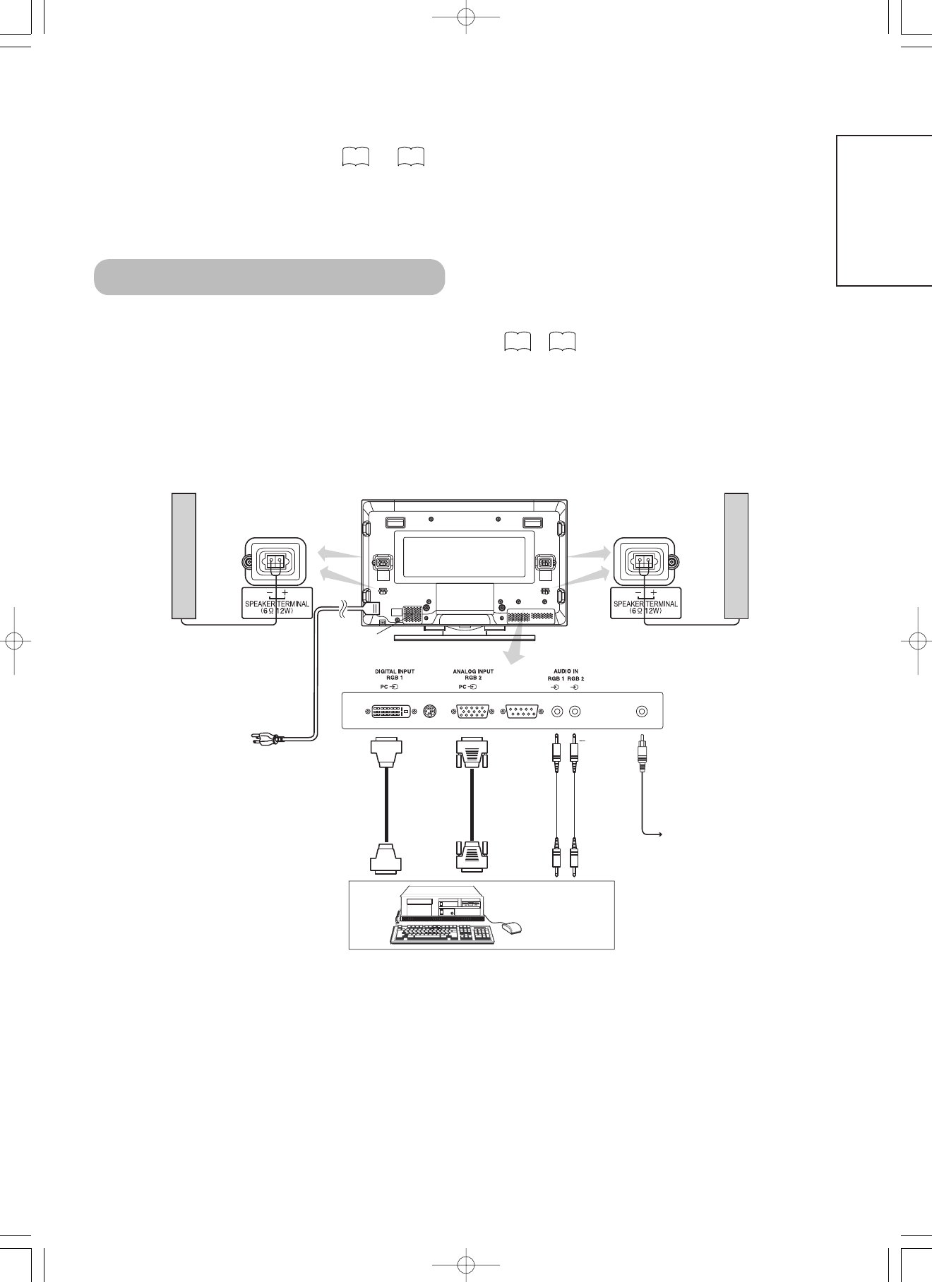
RGB1 audio input terminal (3.5mm Stereo Mini Jack)
RGB2 analog RGB input terminal (D-sub 15-pin)
RGB2 audio input terminal (3.5mm Stereo Mini Jack)
Video signals
0.7 V/1.0 Vp-p, analog RGB (Recommended Signal)
Sync signals
H/V separate, TTL level [2KΩ]
H/V composite, TTL level [2KΩ]
Sync on green, 0.3 Vp-p [75Ω]
Recommended signal
44 modes
Signal Input (continued)
12345678
910111213141516
17181920212223
24
PRODUCT SPECIFICATIONS (continued)
DVI terminal (DVI-D)
PinInput signalPinInput signal
1
T.M.D.S. Data2-
14
+5V Power
2
T.M.D.S. Data2+
15
Ground (for+5V)
3
T.M.D.S. Data2/4 Shield
16
Hot Plug Detect
4
T.M.D.S. Data4-
17
T.M.D.S. Data0-
5
T.M.D.S. Data4+
18
T.M.D.S. Data0+
6
DDC Clock
19
T.M.D.S. Data0/5 Shield
7
DDC Data
20
T.M.D.S. Data5-
8
No Connect
21
T.M.D.S. Data5+
9
T.M.D.S. Data1-
22
T.M.D.S. Clock Shield
10
T.M.D.S. Data1+
23
T.M.D.S. Clock+
11
T.M.D.S. Data1/3 Shield
24
T.M.D.S. Clock-
12
T.M.D.S. Data3-
FrameGND
13
T.M.D.S. Data3+
With Digital RGB signal input (RGB1 input)
Recommended Signal List
No.
Signal mode
Horizontal frequency
(kHz)
Dot clock frequency
(MHz)
Remarks
Signal NameResolution
Vertical frequency
(Hz)
WVGA type : On
(55" only)
• Make sure that the signal of the equipment to be connected is compatible with the specifications of this list.
ENGLISH
• The type of video board or connecting cable used may not allow for correct displays adjustment of Horizontal Position, Vertical Position, Horizontal
Clock and Clock Phase.
• The monitor may fail to display an animation image correctly when a signal having a vertical frequency of 85Hz or higher is input to it.
• The monitor differentiates the signal modes according to the horizontal and vertical frequencies and the horizontal and vertical sync signal
polarities. Note that different signals having all these elements alike may be handled as the same signal.
• Displaying images with more than 512 lines of vertical resolution at Full diplay (compressed display) can result in the interpolation of stripes.(37")
• Displaying images with more than 768 lines of vertical resolution at Full diplay (compressed display) can result in the interpolation of stripes.(55")
With Analog RGB signal input (RGB2 input)
Signal mode
Horizontal frequency
(kHz)
Dot clock frequency
(MHz)
Remarks
Signal NameResolution
Vertical frequency
(Hz)
WVGA type : On
WXGA Mode: 1280x768
(55" only) 1366 x 768
SUPPLEMENT
ENGLISH
Optional Video Unit Function
Additional functions when the optional video unit is installed are as follows: ( )
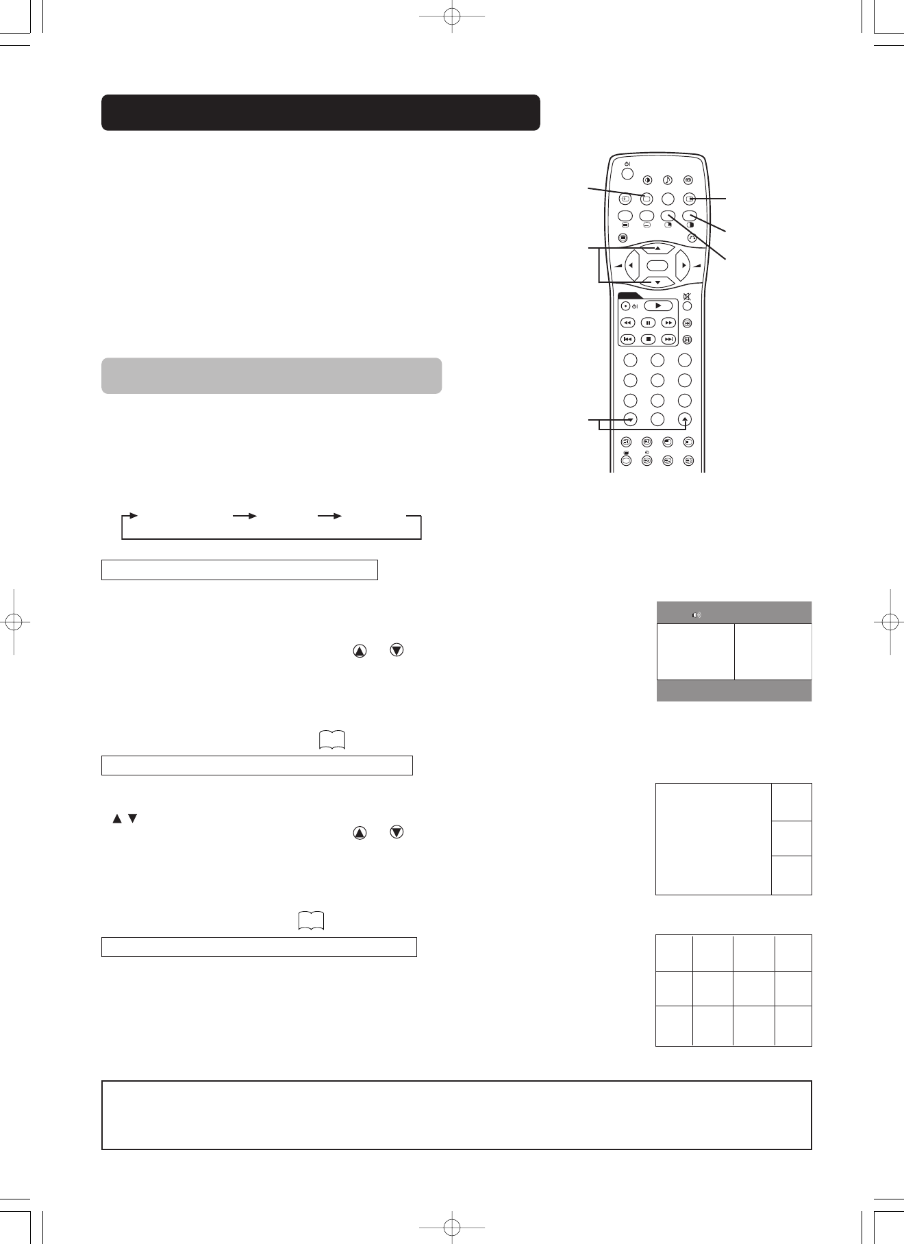
COMPONENT NAMES
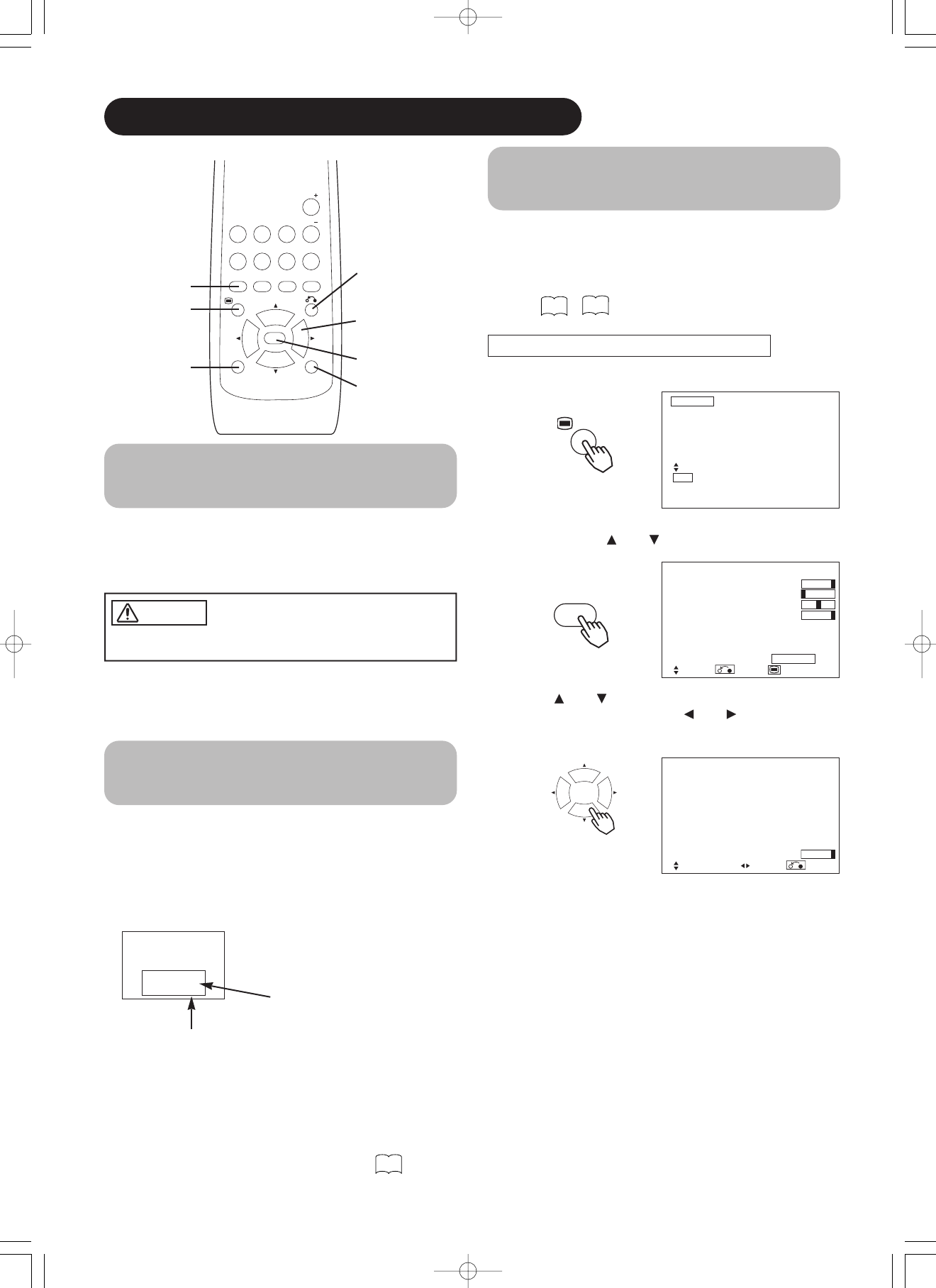
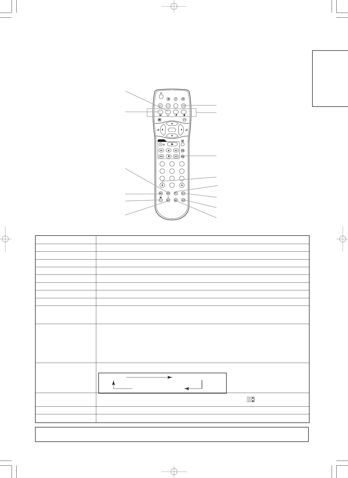
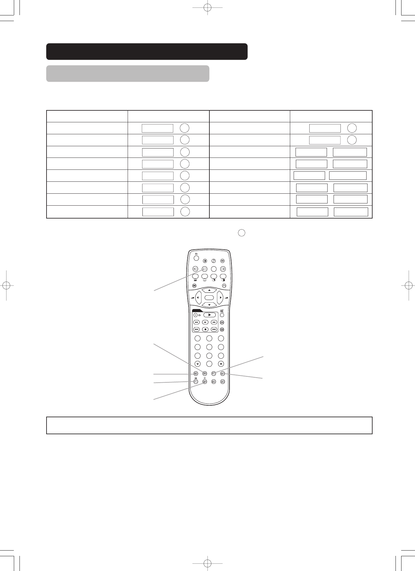
Remote control (provided for the optional video unit)
POWER ON / OFF button
PICTURE MODE button
Loading Batteries
1. Open the battery cover.
• Slide back and remove the battery
cover in the direction of the arrow.
2. Load batteries.
• Load two Size AA batteries included
observing the correct polarities.
3. Close the battery cover.
• Replace the battery cover in the
direction of the arrow and snap it back
into place.
Use the remote control within about 5 m from front of the unit’s
remote-control sensor and within 30 degrees on both sides.
With in 30
degrees
About 5m
About 3m
With in 30
degrees
About 3m
D / N
A / B
i
+
MENU
OK
FREEZE
ZOOM
AV1
RGB1RGB2
AV2AV3AV4
2-4-12
I / II
P+
P-
+-
DVD
123
456
78
0
9
• Do not use new and old batteries together. The batteries could
explode or leak, resulting in fires, physical injury, or stains.
• When loading batteries, observe their correct polarities as marked
on the product. If loaded in the wrong direction, the batteries
could explode or leak, resulting in fires, physical injury, or stains.
CAUTION
ATTENTION
• Do not drop or impact the remote control.
• Do not splash the remote control with water or put it on a wet
object to avoid possible failures.
• Before leaving the remote control out of use for an extended
period of time, remove the batteries from it.
• If the remote control begins to lack responsiveness, replace the
batteries.
• Strong light such as direct sunlight impinging on the
photoreceptor of the remote control can cause operational
failure. Position this unit to avoid direct contact with such light.
Handling the Remote Control
AUDIO MODE button
RECALL button
INPUT SELECT button
MULTI PICTURE (PinP) button
RETURN button
MENU button
SELECT / ADJUST buttons ( )
VOLUME UP / DOWN buttons
OK button
DVD CONTROL buttons
MUTE button
ZOOM button
RGB / VIDEO buttons
This type of remote control would be provided for the optional video unit as the substitute for the one shown in page .
D / N
A / B
i
+
MENU
OK
FREEZE
ZOOM
AV 1
RGB1RGB2
AV 2AV3AV 4
2-4-12
I / II
P+
P-
+-
DVD
123
456
78
0
9
Buttons for MULTI PICTURE mode
FREEZE button
COMPONENT NAMES (continued)
Remote control (provided for the optional video unit) (continued)
DynamicNatural
MovieMusic
FavoriteSpeech
D / N
A / B
i
+
MENU
OK
FREEZE
ZOOM
AV1
RGB1RGB2
AV2AV3AV4
2-4-12
I / II
P+
P-
+-
DVD
123
456
78
0
9
PICTURE MODE
You may recall the picture mode by
pressing this button. Each time pressed,
picture mode is changed in following
sequence.
INPUT SELECT
Press this button to change input
mode.
DVD CONTROL
You can use these buttons to operate
the selected brand of DVD player.
AUDIO MODE
You may recall the sound mode by pressing
this button. Each time pressed, sound mode
is changed in following sequence.
MATRIX SURROUND
Press this button to set Matrix
Surround On or Off.
MULTI PICTURE
Press this button to change the
screen to multi-pictures. Press it
again to return to normal picture.
MUTE
Press this button to turn off the set
sound. When press again or the _
volume up button will restore the sound.
ZOOM
Press this button can change Picture size.
DISPLAYING MULTI PICTURE
Refer to
FREEZE
Press this button to change the
picture to freeze mode. Press it again
to return to normal picture.
RECALL
Refer to
ENGLISH
Use if the
video
equipment
has an
S video
input terminal
To S video output
terminal
To audio output
terminals
To audio output
terminals
To component
output terminals
To component
output terminals
To component
input terminals
To component
input terminals
To composite
input terminal
To audio output
terminals
To audio input
terminals
2018161412108642
21
1917
1513119
7
5
31
VTR
VTR
DVD playerSet-Top Box
Video disc player
Adaptor
To composite
output terminal
S-video/Composite video
Do not connect both
plugs at the same time.
Use either of them.
S-video can not
be used.
Adaptor
with Cable
(37")(55")
(1) Make sure that the power switch of the monitor is turned off.
(2) Make sure that the power switch of the imaging device is turned off.
(3) Use a commercially available cable and connector to connect the signal input terminal on the rear panel of this
device and the signal output terminal of the imaging device.
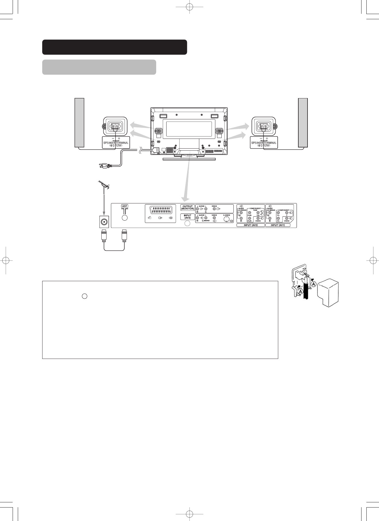
INSTALLATION INSTRUCTIONS
Connecting to a Video Imaging Device
• If video equipment with an S video output terminal is used, cabling
by the S video cable is recommended to provide finer video
quality. (If an S video input terminal and a video input terminal of
AV3 connect to the monitor at the same time, S video input would
govern.)
• If the OUTPUT (MONITOR) terminal is connected to an external
monitor with a 75 Ohm terminal, it is possible to view the same
image as on the main unit. But it is possible to monitor only the
composite video signal from AV1, AV2, AV3 or AV4 input that is
displayed on the screen at the time.
• If the adaptor is applied to AV4 input as shown in the drawing, it is
not possible to receive RGB signal.
With RGB component setup
SUB WOOFER
(55")
To audio sub woofer
To component video
equipments.
Please use the connection
cable suitable for the terminal
form of video equipment.
[An example of connecting video imaging devices]
Applicable video signals for each input terminal (See PRODUCT SPECIFICATIONS for details. )
TerminalRCA/SCARTDVID-subRemarks
SignalCVBSS-videoComponentRGBPCSTBRGBComponent
AV1
AV2Refer to Setup Menu.
AV3
AV4Refer to Setup Menu.
RGB1Refer to Setup Menu.
RGB2Refer to Setup Menu.
(
Monitor rear panel
Speaker (R)
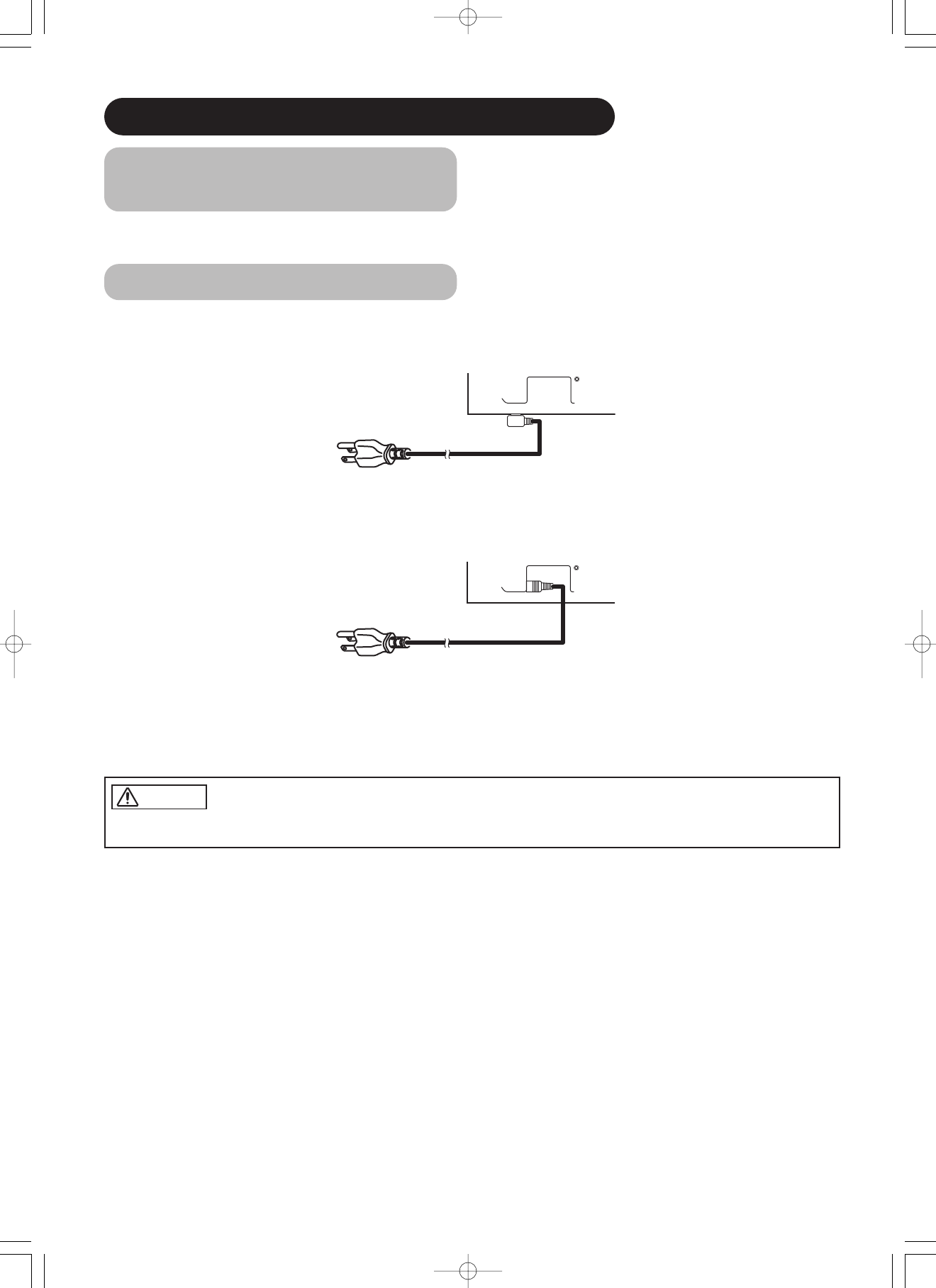
Speaker (L)
Power
cord
(37")
(55")
(37")
(55")
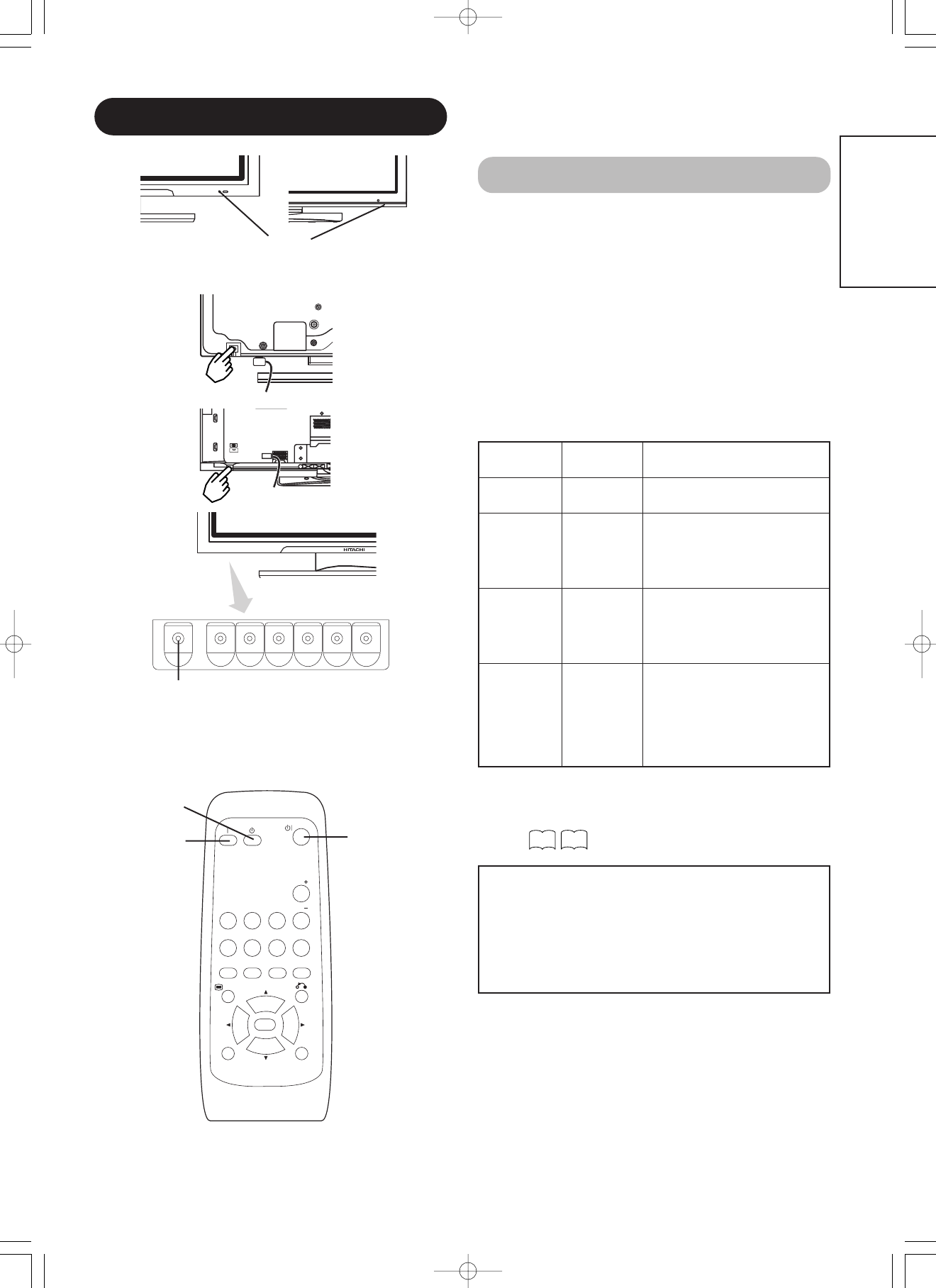
OPERATING INSTRUCTIONS
Input Switching
Input can be switched by pressing the AV1, AV2, AV3,
AV4, RGB1 or RGB2 buttons of the remote control.
Input can be switched in the sequence of AV1 AV2
AV3 AV4 RGB1 RGB2 by pressing the INPUT
SELECT button of the monitor.
AV1 AV2 AV3
RGB2 RGB1 AV4
INPUT SELECT button
RGB/VIDEO
buttons
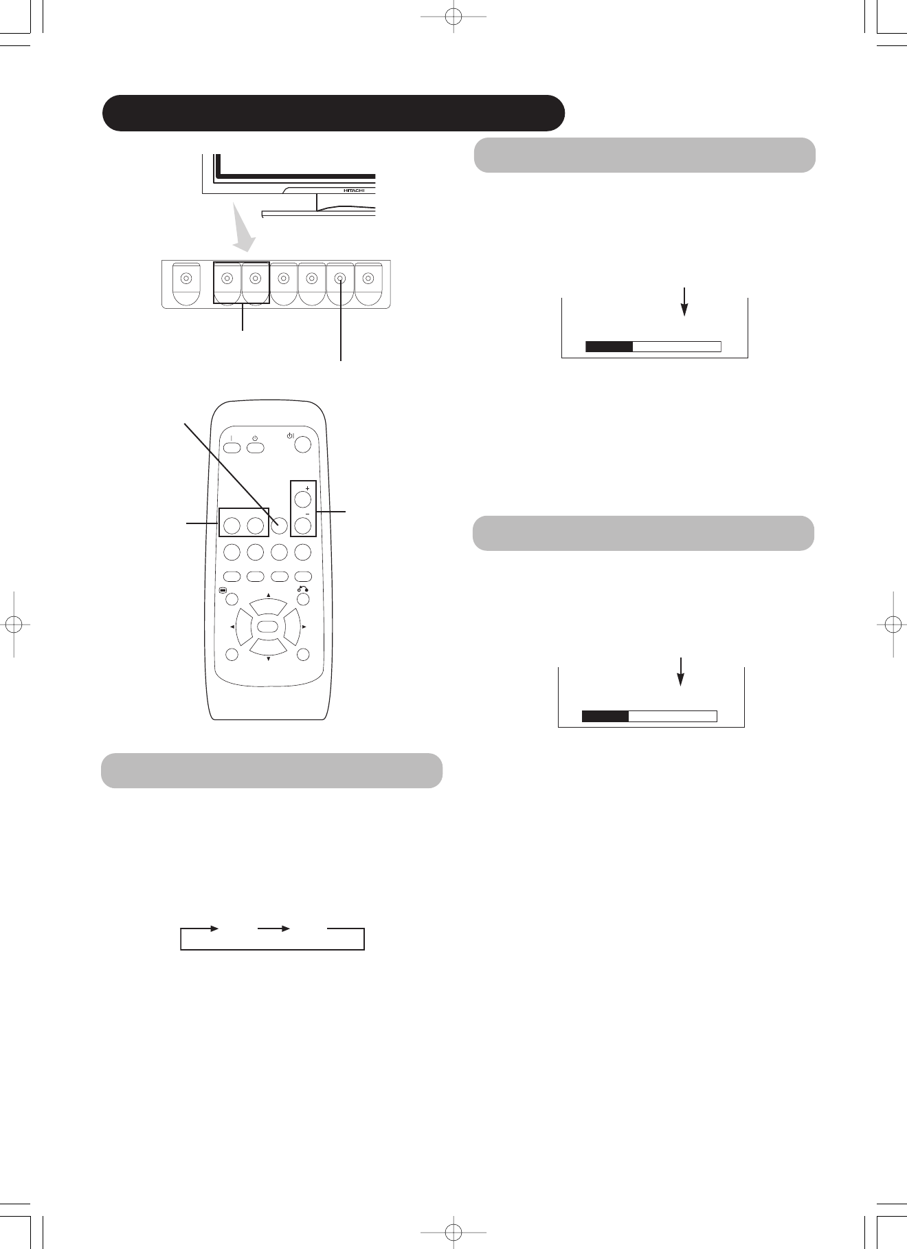
SIZE button
Each time the ZOOM button of the remote control or the
monitor is pressed, the screen display size will change in
sequence and the status will be displayed at the bottom
of the screen.
Full
Size Switching
• During VIDEO signal input (AV1, AV2, AV3, AV4, RGB1
(set to [DVI-STB]) and RGB2 (set to [Component]))
• The size will fix as Full mode and not change when receiving the
component signal of 1080i/50, 1080i/60 or 720p/60.
4:3 Panoramic Zoom
Full Cinema
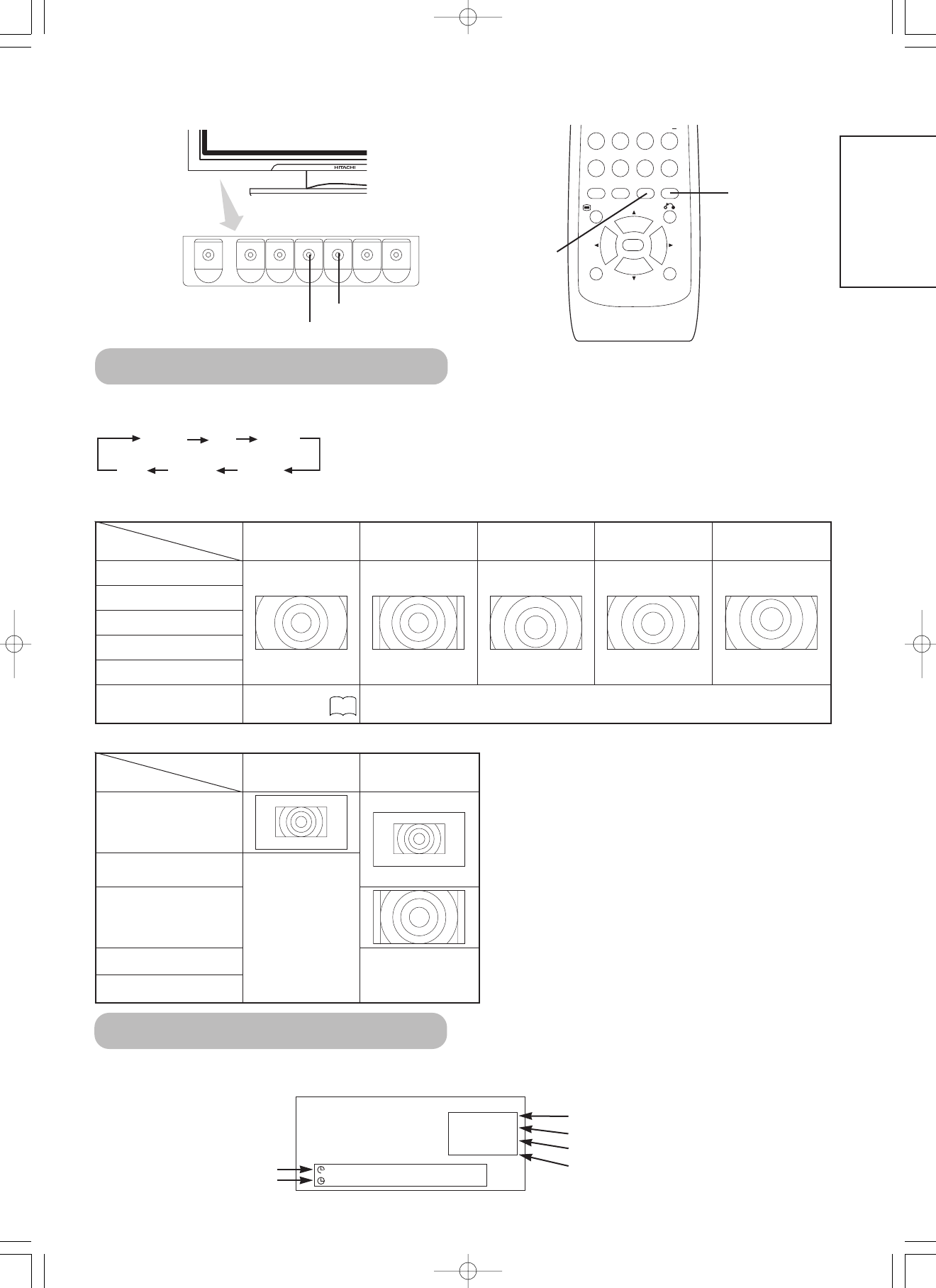
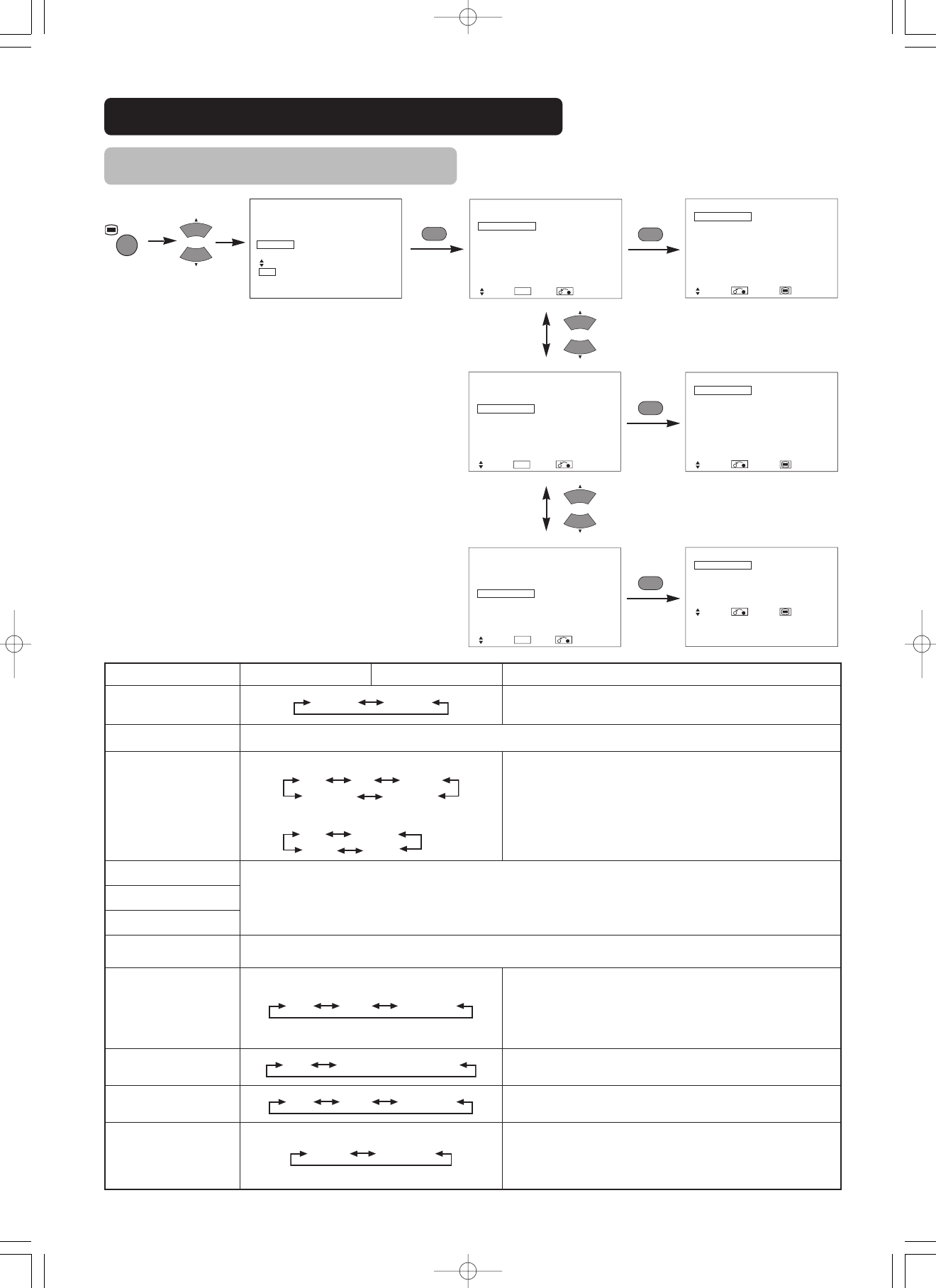
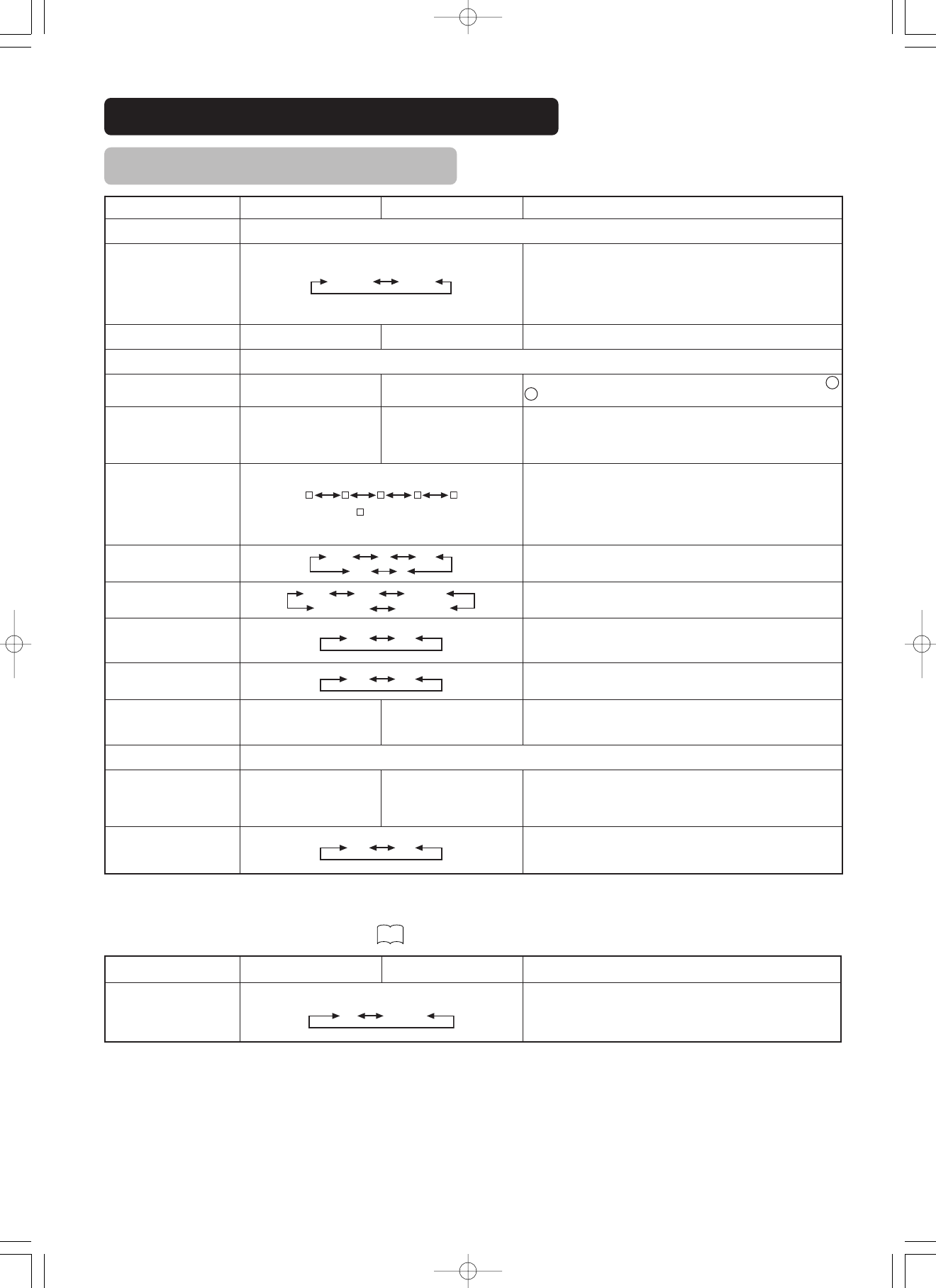
Display size selection diagram
When you want to
Set the display size to
Input signalDisplay screenRemarks
Play a 4:3 image in a 16:9 screen faithfully.
43
Blanking occurs on both sides.
Play a 4:3 image in a 16:9 screen with the
height and width of the middle of the
screen enlarged on equal scales and with
both sides appearing somewhat enlarged.
Panoramic
Play a 16:9 VISTA size image in the 4:3
image faithfully reproduced on the 16:9
screen.
Zoom
• The 4:3 image is called a letterbox image.
• In some cases, some slight blanking may
remain at the top and bottom.
Play a 21:9 Cinema size image in the 4:3
image expanded vertically on the 16:9
screen.
Cinema
In some cases, some slight blanking may
remain at the top and bottom.
Play a 4:3 image faithfully in a 16:9 screen
in the standard vertical size and
horizontally squeezed.*
Full
* An image with an aspect ratio of 16:9
shrunk horizontally to 4:3 to display in a 4:3
screen
(4:3 signal)
(Squeeze)
(Vista)
(Cinema)
ZOOM button
FREEZE
ZOOM
AV 1
RGB1RGB2
AV 2AV3AV 4
DVD
123
456
78
0
9
ENGLISH
ATTENTION
Using a wide-screen monitor
• This monitor has a screen mode selection feature. If an incompatible screen mode is selected to play certain software, such as a TV program,
the image would appear different from the original. Take this into consideration when making screen mode choices.
• Use of this monitor in its enlarged display mode with the wide feature enabled in coffee shops, hotels and other establishments for
commercial or pubic viewing purposes could infringe on the copyright holder’s right protected by Copyright Law.
• When a normal 4:3 image is displayed over the entire screen in the Panoramic mode, parts of the periphery of the image may disappear
and/or appear distorted in some cases. Use the 4:3 mode to view images, which were created in 4:3 mode.
This mode allows 4:3 content to be viewed without picture distortion.
Press
Vertical picture position can be adjusted for [Panoramic], [Zoom] and [Cinema] mode as follows.
1. Press SIZE button and SELECT buttons during picture size display.
2. Position display will appear.
3. Adjustment range of each picture size are as shown below.
[Panoramic]- 12 to + 12
[Zoom] and [Cinema] - 31 to + 31
4. When 1080i/50 or 1080i/60 component signal is received, vertical position can be adjusted only one step up. (The range: 0 to +1)
Position + 31Position - 31
Press
Automatic Adjustment of
Screen Position and the Clock
Refer to
Independent Operation of
Multiple Monitors (ID No)
This function is not available.
OPERATING INSTRUCTIONS (continued)
Displaying MULTI PICTURE
If the PinP button on the remote control is pressed MULTI
PICTURE will display.
Activating the P-in-P mode from the RGB input screen
Pressing the PinP button one time will display 2 pictures.
• This mode can be available from RGB1(DVI-PC) and RGB2(RGB)
input.
• The speaker icon can be shifted Up and Down by pressing the
SELECT buttons; the audio of the video will be output from the side
on which the speaker icon is located.
• The sub-screen position can be
selected up and down by pressing
SELECT buttons.
• The sub-screen can be selected with
the AV1, AV2, AV3, and AV4 buttons
from the status that the speaker icon
appears on the left side of AV✱as
shown in the diagram to the right.
• Pressing the PinP button again or
the RETURN button will cancel the 2 pictures display.
• "Frequency Mode" in the Setup Menu should be set to Movie when
sub-screen is the component signal of 1080i/50 or 1080i/60.
AV1: Displays the VIDEO input signal of the sub-screen.
Activating the Split mode from the video input screen
Pressing the PinP button one
time will display 2 pictures.
• The speaker icon can be shifted
left and right by pressing the
SELECT buttons; the audio of the
video will be output from the side on
which the speaker icon is located.
• The same video input mode cannot
be selected for both screens at the
same time.
• Pressing the PinP button again or the RETURN button will cancel
the 2 pictures display.
•
When the Video input is set to RGB Video, this Split mode is not possible.
•
Refer to the table for 2 pictures (Split) mode.
RECALL button
RETURN button
RECALL button
RGB2
AV1
(Sub-
screen)
AV1AV2
2 Pictures (Split)
MainSub
The input signal status can be displayed on the screen
by pressing the RECALL button of the remote control or
the monitor.
The display will go out in approximately 6 seconds.
AV1
Composite
-- -- Min.
-- -- : -- --
OFF
Input Signal Screen Display
Input mode
Signal mode
Off-timer
On-timer
VIDEO
NOTE
• Even if the input of the horizontal / vertical synchronizing signal (or video signal) stops in the MULTI PICTURE display, the mode will not
change to power save mode.
• Please be careful since image retention will occur if display is left in a MULTI PICTURE display state for a long period of time.
Input terminal
AV1AV4
AV1, AV2RGB1RGB2
PAL
SECAM
NTSC3.58
NTSC4.43
576i
576p
480i
480p
1080i/501080i/60720p/60STBComponent
AV1
AV4
PAL, SECAM
NTSC3.58/4.43
AV1
AV2
576i, 576p
480i, 480p
1080i/50
1080i/60
720p/60
RGB1STB
RGB2Component
(
Main
Sub
MULTI PICTURE
(PinP) button
D / N
A / B
i
+
MENU
OK
FREEZE
ZOOM
2-4-12
I / II
P+
P-
+-
DVD
123
456
78
0
9
FREEZE button
A / B
A / B
ENGLISH
Picture
Audio
Timer
Function
Setup
Language
Select
OK Set
Picture
Picture Mode Dynamic
Contrast +31
Brightness -31
Color 0
Sharpness +15
Tint 0
Color Temperature Normal
Contrast Mode Normal
Reset Reset
Select Set Return
OK
Auto Color Off
Next/Prev On/Off Return
MENU
Picture Dynamic
YNR Off
CNR Off
Film Mode On
PAL Comb Filter On
LTI Off
CTI Off
Black Enhancement Off
Auto Color Off
Reset Reset
Select Set Return
OK
Contrast Mode Normal
Next/Prev Select Return
OK
Picture
Picture Mode Dynamic
Contrast +31
Brightness -31
Color 0
Sharpness +15
Tint 0
Color Temperature Normal
Contrast Mode Normal
Reset Reset
Select Set Return
OK
Picture Dynamic
Color Temp. Adjust
Color Management
Color Decoding
Select Set Return
OK
Picture Dynamic
Color Temp. Adjust
Color Management
Color Decoding
Select Set Return
OK
Picture
Color Management On
Magenta + 60
Red + 30
Yellow 0
Green + 60
Cyan + 30
Blue 0
Reset Reset
Select On/Off Return
OK
OK
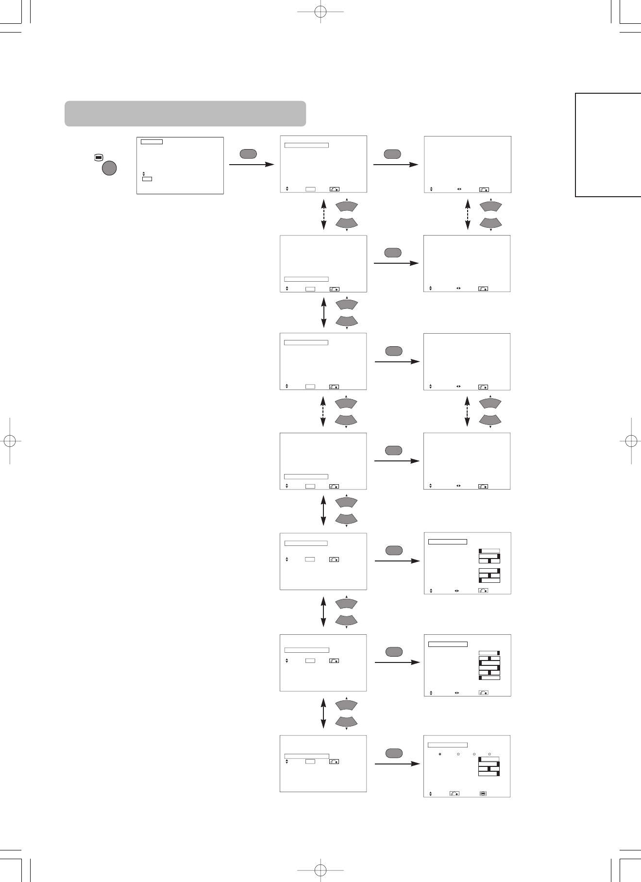
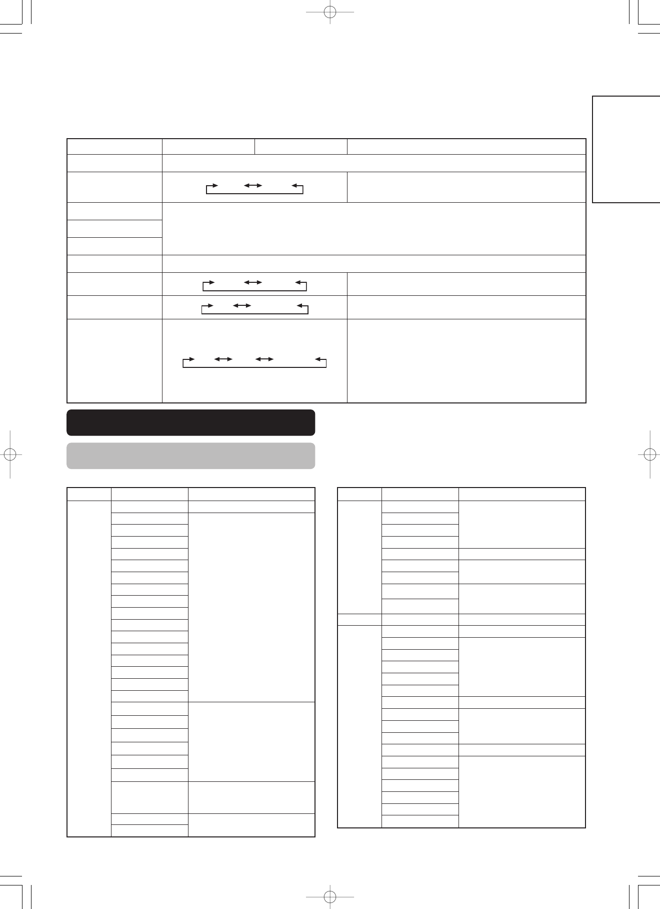
PICTURE MENU
OK
OK
Picture Mode Dynamic
Next/Prev Select Return
YNR Off
Next/Prev Select Return
Picture Dynamic
YNR Off
CNR Off
Film Mode On
PAL Comb Filter On
LTI Off
CTI Off
Black Enhancement Off
Auto Color Off
Reset Reset
Select Set Return
OK
Picture
Color Temp. Adjust On
Amplitude
Red – 63
Green 0
Blue – 31
Cut Off
Red + 31
Green 0
Blue + 31
Reset Reset
Select On/Off Return
Picture Dynamic
Color Temp. Adjust
Color Management
Color Decoding
Select Set Return
OK
OK
OK
Picture
Color Decoding
RGB R G B
Red 0
Green + 60
Color 0
Tint + 31
Reset Reset
Select Return Exit
OK
OPERATING INSTRUCTIONS (continued)
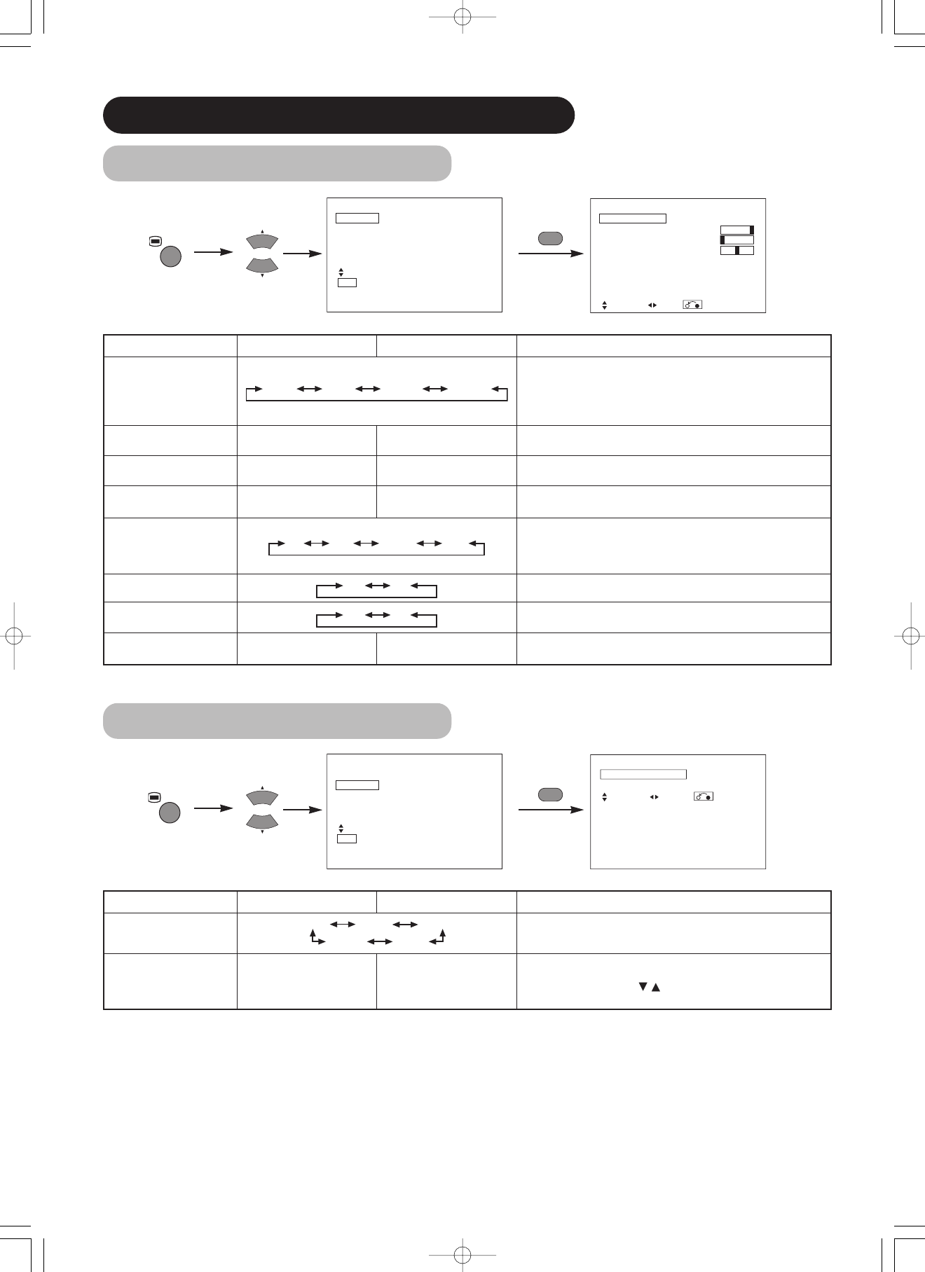
PICTURE MENU (continued)
Selected charactersSetup hint
Picture Mode
Dynamic Natural
Dynamic: This setting is best for very bright ambient lighting.
Natural: This setting is for normal lighting conditions.
Contrast
Narrows the gap between
brightness and darkness.
Broadens the gap between
brightness and darkness.
Adjust for maximum visibility to suit the ambient brightness.
This can adjust further till [+40] by pressing and holding cursor
button at [+31]. The color for [+32] to [+40] numbers will change from
white to magenta. This special mode is better for dark scenes.
For normal viewing we recommend that the Contrast is set to [+31].
"Panel Life" in the Function Menu should be set to Normal when this
Contrast setting is adjusted.
Brightness
Black is subdued for
increased overall darkness.
Black is set off for increased
overall brightness.
Adjust to taste.
Color
Darkens colors.Lightens colors.Adjust to taste.
Sharpness
SoftSharp
Normally set to Centre position Shift to the minus (-) side for a softer
effect and plus (+) for sharper picture.
Tint
Enhances red and weakens
green.
Enhances green and weakens
red.
This is not available to adjust when receiving PAL/SECAM signal.
Then the character will be grayed out.
Adjust for most realistic skin color.
Color Temperature
Cool Normal Warm Black / White
Adjust to taste.
Contrast Mode
Normal Auto Dynamic
Dynamic:Emphasizes the differences between video shadings to
improve the feeling of contrast.
Normal : The gradation of an image is reproduced as faithfully as
possible.
Auto:Detects image brightness and automatically adjusts for natural
brightness.
Reset
(off the function)(waiting to reset)
The original factory settings for the items of this Menu page can be
restored by pressing the OK button.
YNR
Off Low High
Performs picture signal noise reduction. Turn up to reduce noise.
CNR
Performs color signal noise reduction. Turn up to reduce noise.
And it will be fixed as Off only when selecting DVI-STB mode.
Film Mode
Off On
On:Automatically detects the movie film material and faithfully
reproduces the original film image.
Off:Set to OFF when switching between images does not appear
natural.
PAL Comb Filter
Off On
This is available only when receiving a PAL composite signal. Turn On
to reduce the discolorations in fine picture detail and provides purer
color.
LTI
Off Low Middle High
Adjusts the sharpness of the picture signal.
CTI
Adjusts the sharpness of the color signal.
Black Enhancement
Adjusts the black level compensation.
Auto Color
Off On
This is available only when receiving an NTSC composite/S.Video
signal. This monitors and adjusts the color to maintain constant color
levels. It also maintains natural flesh tones while preserving fidelity of
background colors.
Color Temp. Adjustment
Off On
Turn On when you wish to change color temperature depending on
the user's preference.
Amplitude
Red
Brighter scene is decreased in
reddish color.
Brighter scene is increased in
reddish color.
Adjust color temperature depending on the user’s preference. These
settings are independently stored in each of the 4 Color Temperature
modes.
Green
Brighter scene is decreased in
greenish color.
Brighter scene is increased in
greenish color.
Blue
Brighter scene is decreased in
bluish color.
Brighter scene is increased in
bluish color.
Cut Off
Red
Dark scene is decreased in
reddish color.
Dark scene is increased in
reddish color.
Green
Dark scene is decreased in
greenish color.
Dark scene is increased in
greenish color.
Blue
Dark scene is decreased in
bluish color.
Dark scene is increased in
bluish color.
ENGLISH
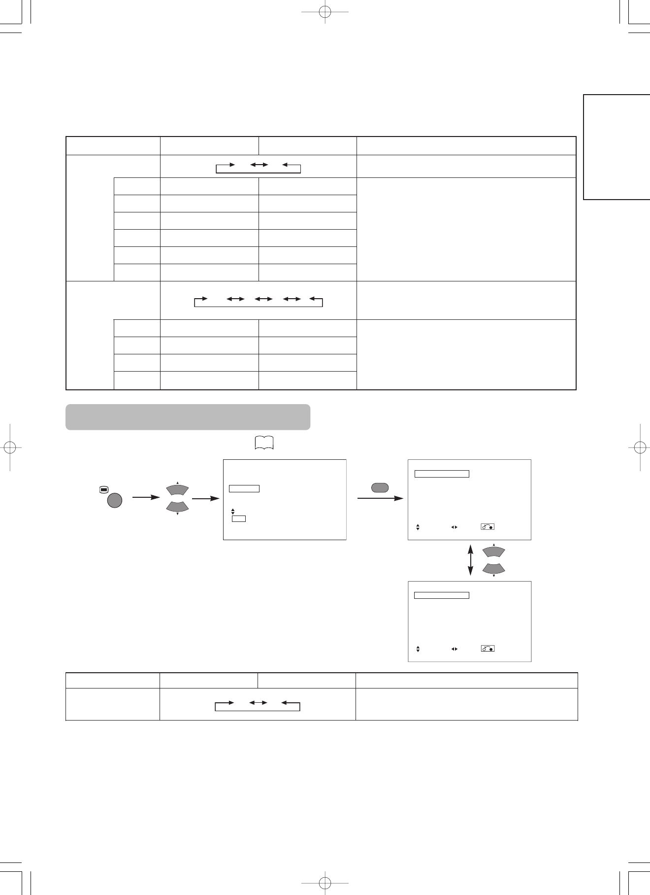
Selected charactersSetup hint
Color Management
Off On
Turn On when the original balance of each color is required to adjust
depending on the user’s preference.
Magenta
Magenta is weakened.Magenta is strengthened.
This adjusts listed colors individually to make them either deeper or
more pure. These settings are independently stored in each of the 4
Color Temperature modes.
Red
Red is weakened.Red is strengthened.
Yellow
Yellow is weakened.Yellow is strengthened.
Green
Green is weakened.Green is strengthened.
Cyan
Cyan is weakened.Cyan is strengthened.
Blue
Blue is weakened.Blue is strengthened.
Color Decoding
RGB R G B
Select the single color screen when that is required to adjust R/G/B
level individually depending on the user’s preference. And set it back
to RGB mode that indicates all color after adjusting.
Press the OK button every time the setting is changed.
Red
Darkens red only.Lightens red only.
This adjusts R/G/B level or tint to make the color appear natural for
the user’s preference. These settings are independently stored in
each of the 4 Color Temperature modes.
Green
Darkens green only.Lightens green only.
Color
Darkens colors.Lightens colors.
Tint
Enhances red and weakens
green.
Enhances green and weakens
red.
FUNCTION MENU
1 item is added to the Menu shown in the page .
Picture
Audio
Timer
Function
Setup
Language
Select
OK Set
Function
Screen Saver Off
Screen Wipe On 60Min.
Black Side Panel Off
Video Power Save Off
Freeze Mode Split
Default Zoom Panoramic
Reset Reset
Select Set Return
OK
MENU
Function
Panel Life Normal
Mode Display Off
ID Number 1
Inverse On 60Min.
Standby White Off
Gamma 2.2
Reset Reset
Select Set Return
Selected charactersSetup hint
Video Power Save
Off On
This is used to reduce power consumption for video input when there
is no video signal. Setting it On will leads the monitor to the standby
mode when the AV input with no signal is selected.
OPERATING INSTRUCTIONS (continued)
SETUP MENU
Picture
Audio
Timer
Function
Setup
Language
Select
OK Set
Setup
System System 1
Color System
Video Input
Audio Input
Scart Output Monitor
RGB1 DVI-STB
RGB2 Component
HDTV
Select Set Return
OK
Setup
System System 1
Color System
Video Input
Audio Input
Scart Output Monitor
RGB1 DVI-STB
RGB2 Component
HDTV
Select Set Return
OK
OK
MENU
OK
Setup
Color System
AV1 Auto
AV2 PAL
AV3 SECAM
AV4 PAL
Select Return Exit
Setup
System System 1
Color System
Video Input
Audio Input
Scart Output Monitor
RGB1 DVI-STB
RGB2 Component
HDTV
Select Set Return
OK
OK
Setup
Video Input
AV1 Auto
AV2 Composite/Component
AV3 Auto
AV4 S.Video
Select Return Exit
OK
Setup
Audio Input
AV1 Stereo
AV2 L/Mono
AV3 Stereo
AV4 L/Mono
Select Return Exit
Selected charactersSetup hint
System
System1 System2
System1 : Europe/Asia, System2 : North America
Color System
AV1
Auto PAL SECAM
System1
System2
NTSC3.58 NTSC4.43
Auto NTSC-M
PAL-N PAL-M
This should correspond to the color system of the signal from the
equipment that is connected to AV1 video input terminal.
• Normally, set this to Auto. The system of the input signal will be
automatically recognized.
• If the input signal contains much noise or has a low level at Auto and the
operation is found erratic, set this to match the input signal.
• When the component signal is received, this would be not available
(grayed out).
AV2
(Same to AV1)
AV3
AV4
Video Input
AV1
Auto HDTV SDTV/DVD
This should correspond to the signal mode of the signal from the
equipment that is connected to AV1 video input terminal.
• Normally, set this to Auto. The signal mode of the input signal will be
automatically recognized.
• If the input signal contains much noise or has a low level at Auto and the
operation is found erratic, set this to match the input signal.
AV2 (1st step)
RGB Composite/Component
This should correspond to the signal mode of the signal from the
equipment that is connected to AV2 video input terminal.
AV2 (2nd step)
Auto HDTV SDTV/DVD
This step should be set only when [Composite/Component] is selected on
the 1st step. And the procedure is same to AV1.
AV4
S.Video Composite
• If the signal from the equipment that is connected to AV4 Scart input
terminal is S.Video or Composite, set this to correspond to that signal.
• If the signal is RGB, it will be automatically recognized and this setting
will have no effect.
ENGLISH
Approximately 1 sec. after adjustment is completed, the adjustments will be recorded as shown in the table below.
OTHER FEATURES
Automatic Store
MenuDisplayRegistration condition
Picture
Picture Mode1 setting is registered.
Contrast
For every input function and every
Picture Mode, 1 setting is
registered.
Brightness
Color
Sharpness
Tint
Color Temperature
Contrast Mode
YNR
CNR
Film Mode
PAL Comb Filter
LTI
CTI
Black Enhancement
Auto Color
Color Temp. Adjust
R Amplitude
For every Color Temperature, 1
setting is registered.
G Amplitude
B Amplitude
R Cut Off
G Cut Off
B Cut Off
Color Management
For every input function and every
Picture Mode, 1 setting is
registered.
Magenta
1 setting is registered.
Red
MenuDisplayRegistration condition
Picture
Yellow
1 setting is registered.
Green
Cyan
Blue
Color Decoding
-
Red
For every Color Temperature, 1
setting is registered.
Green
Color
For every input function and every
Picture Mode, 1 setting is
registered.
Tint
FunctionVideo Power Save1 setting is registered.
Setup
System1 setting is registered.
Color System
1 setting is registered.
AV1
AV2
AV3
AV4
Video Input-
AV1
1 setting is registered.
AV2
AV4
Audio Input-
AV1
1 setting is registered.
AV2
AV3
AV4
RGB1
RGB2
• The previously recorded items will be lost.
Selected charactersSetup hint
Audio Input
AV1
Stereo L/Mono
This should correspond to the audio signal from the equipment that is
connected to AV1 audio input terminal. If it is monaural audio, set this to
L/Mono.
AV2
(Same to AV1)
AV3
AV4
Scart Output
Not Available (grayed out)
RGB1
DVI-PC DVI-STB
This should correspond to the signal mode of the signal from the
equipment that is connected to RGB1 DVI terminal.
RGB2 (1st step)
RGB Component
This should correspond to the signal mode of the signal from the
equipment that is connected to RGB2 D-sub terminal.
RGB2 (2nd step)
Auto HDTV SDTV/DVD
This step should be set only when [Component] is selected on the 1st
step.
This should correspond to the signal mode of the signal from the
equipment that is connected to RGB2 D-sub terminal.
• Normally, set this to Auto. The signal mode of the input signal will be
automatically recognized.
• If the input signal contains much noise or has a low level at Auto and the
operation is found erratic, set this to match the input signal.
Make the checks suggested below depending on the symptoms observed. If the symptoms remain uncorrected, contact your dealer.
Customer servicing can be hazardous.
WARNING
SymptomPoint to checkSee page
• The screen becomes dark and the images cannot be seen
during VTR special playback (fast forward, rewind).
• This sometimes occurs when a component output VTR such as the
480i is connected.
This is not a malfunction; therefore, please take note that this may
occur. When it does occur, change to composite output, or S.video
output.
–
TROUBLESHOOTING
Symptoms That Seemingly Appear to be Failures
This table shows the specifications when the optional video unit has been inserted.
PRODUCT SPECIFICATIONS
• The monitor takes at least 30 minutes to attain the status of optimal picture quality.
Panel
Display
dimensions
Approx. 37 inches (814 (H) x 445 (V) mm, diagonal 930mm)Approx. 55 inches (1229 (H) x 691 (V) mm, diagonal 1410mm)
Resolution
1024 (H) x 1024 (V) pixels1366 (H) x 768 (V) pixels
Net dimensions
(excluding Speakers/Stand)
940 (W) x 573 (H) x 99 (D) mm1394 (W) x 857 (H) x 105 (D) mm
Net weight
(excluding Speakers/Stand)
29.0kg63.5kg
Ambient
conditions
Temperature
Operating : 5˚C to 35˚C, Storage : 0˚C to 40˚C
Relative humidity
Operating : 20% to 80%, Storage : 20% to 90% (non-condensing)
AV4: composite video / L/R audio monitor-output terminal (SCART)
Recommended signal
15 modes
ENGLISH
Signal Input
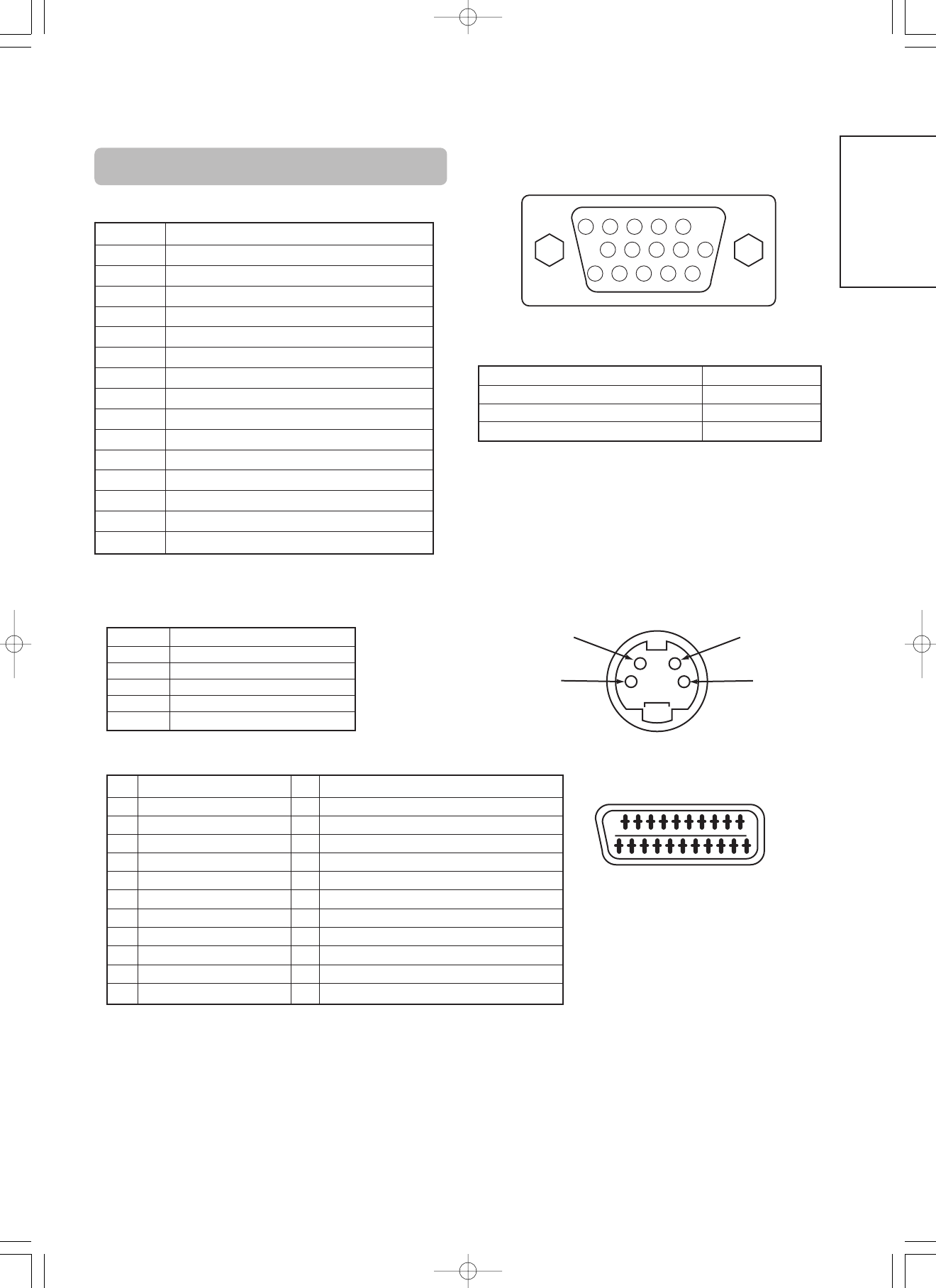
S-input connector pin specifications
PinInput signal
1Y
2Y-GND
3C
4C-GND
FrameGND
2018161412108642
21
1917
1513119
7
5
31
Scart connector pin specifications
PinSignalPinSignal
1
AUDIO OUT (RIGHT)
12
Not Used
2
AUDIO IN (RIGHT)
13
RGB-R GND
3
AUDIO OUT (LEFT/MONO)
14
GND
4
AUDIO GND
15
RGB-R / S.VHS CHROMINANCE IN
5
RGB-B GND
16
BLANKING SIGNAL
6
AUDIO IN (LEFT/MONO)
17
COMPOSITE VIDEO GND
7
RGB-B IN
18
BLANKING SIGNAL GND
8
AUDIO/RGB SWITCH / 16:9
19
COMPOSITE VIDEO OUT
9
RGB-G GND
20
COMPOSITE VIDEO / S.VHS LUMINANCE IN
10
Not Used
21
GND / SHIELD (CHASSIS)
11
RGB-G IN
RGB terminal (D-sub 15-pin connector)
• When different kinds of input signals are simultaneously input to
the monitor via a graphics board or the like, the monitor will
automatically select the signals in the following priority order:
*Even in the case of the recommended signals shown on the
following page, there may be instances when correct display is
not possible. In this case, use H/V separate sync, H/V composite
sync.
Sync signal typePriority
H/V separate sync.1
H/V composite sync.2
sync.on Green *3
PinInput signal
1R (PR/CR)
2G or sync on green (Y)
3B (PB/CB)
4No connection
5No connection
6R.GND (PR/CR, GND)
7G.GND (Y, GND)
8B.GND (PB/CB, GND)
9No connection
10GND
11No connection
12[SDA]
13H. sync or H/V composite sync
14V.sync. [V.CLK]
15[SCL]
( ) : With component input
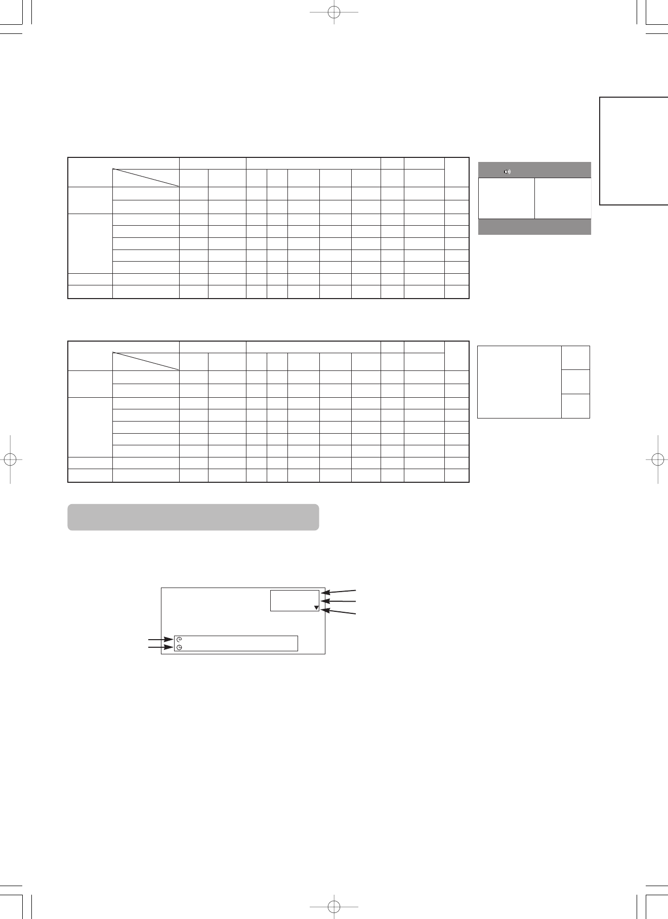
Recommended Signal List
PRODUCT SPECIFICATIONS (continued)
With Digital RGB signal input (RGB1 input)
(
No.
Signal mode
Horizontal
frequency
(kHz)
Dot clock
frequency
(MHz)
Setup Menu Condition
Remarks
Signal NameResolution
Vertical frequency
(Hz)
DVI-PCDVI-STB
WVGA type : On
EIA-861
EIA-861
EIA-861
No.
Signal mode
Horizontal
frequency (kHz)
Dot clock
frequency (MHz)
Remarks
Signal NameResolution
Vertical frequency
(Hz)
1
NTSC4.43
NTSC3.58
52559.9415.73
2
PAL
SECAM
62550.0015.63
With Composite Input(AV1~AV4 input) and S-video Input (AV3 input).
No.
Signal mode
Horizontal
frequency (kHz)
Dot clock
frequency (MHz)
Remarks
Signal NameResolution
Vertical frequency
(Hz)
1
NTSC4.43/3.58
PAL, SECAM
525
625
59.94
50.00
15.73
15.63
With R, G, B Video input (AV2 and AV4 input).
No.
Signal mode
Horizontal
frequency (kHz)
Dot clock
frequency (MHz)
Remarks
Signal NameResolution
Vertical frequency
(Hz)
1576i57650.0015.63
2480i48059.9415.73
3576p57650.0031.26
4480p48059.9431.47
51080i/50108050.0028.13
61080i/60108060.0033.75
7720p/6072060.0045.00
With component input (AV1, AV2 and RGB2-component input).
• The monitor differentiates the signal modes according to the horizontal and vertical frequencies and the horizontal and vertical sync signal
polarities. Note that different signals having all these elements alike may be handled as the same signal.
•
Displaying images with more than 512 lines of vertical resolution at Full diplay (compressed display) can result in the interpolation of stripes.(37")
• Displaying images with more than 768 lines of vertical resolution at Full diplay (compressed display) can result in the interpolation of stripes.(55")
ENGLISH
Optional Tuner Unit Function
The optional tuner unit can operate when installed with the optional video unit.
Additional functions when the optional tuner unit is installed are as follows: ( )
COMPONENT NAMES
Remote control
POWER ON / OFF button
PICTURE MODE button
SURROUND button
Loading Batteries
1. Open the battery cover.
• Slide back and remove the battery
cover in the direction of the arrow.
2. Load batteries.
• Load two Size AA batteries included
observing the correct polarities.
3. Close the battery cover.
• Replace the battery cover in the
direction of the arrow and snap it back
into place.
Use the remote control within about 5 m from front of the unit’s
remote-control sensor and within 30 degrees on both sides.
With in 30
degrees
About 5m
About 3m
With in 30
degrees
About 3m
D / N
A / B
i
+
MENU
OK
FREEZE
ZOOM
AV1
RGB1RGB2
AV2AV3AV4
2-4-12
I / II
P+
P-
+-
DVD
123
456
78
0
9
• Do not use new and old batteries together. The batteries could
explode or leak, resulting in fires, physical injury, or stains.
• When loading batteries, observe their correct polarities as marked
on the product. If loaded in the wrong direction, the batteries
could explode or leak, resulting in fires, physical injury, or stains.
CAUTION
ATTENTION
• Do not drop or impact the remote control.
• Do not splash the remote control with water or put it on a wet
object to avoid possible failures.
• Before leaving the remote control out of use for an extended
period of time, remove the batteries from it.
• If the remote control begins to lack responsiveness, replace the
batteries.
• Strong light such as direct sunlight impinging on the
photoreceptor of the remote control can cause operational
failure. Position this unit to avoid direct contact with such light.
Handling the Remote Control
AUDIO MODE button
RECALL button
INPUT SELECT button
CH I / II button
MULTI PICTURE (PinP) button
Buttons for MULTI PICTURE mode
RETURN button
MENU button
PROGRAM UP / DOWN buttons
SELECT / ADJUST buttons ( )
VOLUME UP / DOWN buttons
OK button
DVD CONTROL buttons
MUTE button
FREEZE button
ZOOM button
PROGRAM SELECT buttons
PROGRAM UP / DOWN buttons
RGB / VIDEO buttons
TIME button
D / N
A / B
i
+
MENU
OK
FREEZE
ZOOM
AV 1
RGB1RGB2
AV 2AV3AV 4
2-4-12
I / II
P+
P-
+-
DVD
123
456
78
0
9
COMPONENT NAMES (continued)
Remote control (continued)
DynamicNatural
MovieMusic
FavoriteSpeech
D / N
A / B
i
+
MENU
OK
FREEZE
ZOOM
AV1
RGB1RGB2
AV2AV3AV4
2-4-12
I / II
P+
P-
+-
DVD
123
456
78
0
9
PICTURE MODE
You may recall the picture mode by
pressing this button. Each time pressed,
picture mode is changed in following
sequence.
INPUT SELECT
Press this button to change input
mode.
RECALL
With this button, the display change
between “--”,“---”,“-” and AV00 on the
top right hand corner of the screen.
“--” is for 2 digit channel selection, “---”
is for 3 digit channel selection and “-” is
for 1 digit channel selection.
DVD CONTROL
You can use these buttons to operate
the selected brand of DVD player.
PROGRAM SELECT
Press these buttons to select a TV
program directly.
TIME
Pressing this button can indicate the
time by On-Screen display when
receiving a TV program on the screen
including TELETEXT service with the
time information.
AUDIO MODE
You may recall the sound mode by pressing
this button. Each time pressed, sound mode
is changed in following sequence.
MATRIX SURROUND
Press this button to set Matrix
Surround On or Off.
MULTI PICTURE
Press this button to change the
screen to multi-pictures. Press it
again to return to normal picture.
CH I/II
This button is for A2 / NICAM
models only.
MULTI MODE
In multi-picture mode, pressing this
button will change the multi-picture
mode.
MUTE
Press this button to turn off the set
sound. When press again or the _
volume up button will restore the sound.
FREEZE
Press this button to change the
picture to freeze mode. Press it again
to return to normal picture.
ZOOM
Press this button can change Picture size.
ENGLISH
D / N
A / B
i
+
MENU
OK
FREEZE
ZOOM
AV1
RGB1RGB2
AV2AV 3AV 4
2-4-12
I / II
P+
P-
+-
DVD
123
456
78
0
9
SUBTITLE button
TV button
TEXT button
COLOR buttons
(RED, GREEN, YELLOW, BLUE)
TEXT / TV
+
TEXT button
TV / TEXT button
MODE button
[Buttons for TELETEXT Mode]
PAGE UP / DOWN button
REVEAL button
HOLD button
INDEX button
SUB PAGE buttons
CANCEL button
U. N. L. button
Buttons on Remote ControlFunction
TEXT
Press this to use the TELETEXT services.
TV
Press this to return to the TV mode when in the TELETEXT mode.
TV / TEXT
This switches the receiver between the TV mode and the TELETEXT mode.
TEXT / TV + TEXT
In TELETEXT mode, this button switches between TV+TEXT screen (split) and TELETEXT only.
MODE
This selects the FASTEXT and FAVORITE modes.
INDEX
This selects the P100 page.
SUB PAGE
This allows receiving of a sub page. When the button is pressed, “S✱✱✱✱” will be displayed at the top left of the screen.
SUB TITLE
Use this to access a subtitle service directly rather than through a TELETEXT service (subject to subtitle service broadcasting).
CANCEL
This allows the screen to return to the TV mode temporarily while searching for a required text page. When the required text
page has been received, the page number will be displayed at the top left of the screen. Press the CANCEL button again to
display the TELETEXT screen.
RED
GREEN
YELLOW
BLUE
Each of these buttons selects a link page displayed at the lower part of the screen.
A FAVORITE page can also be stored in the memory using one of the colors. It can then retrieve the page stored by pressing
the appropriate color button.
To store a FAVORITE page :
• press the MODE button ;
• press a color button for the FAVORITE page ;
• enter the FAVORITE page number to be stored and press the same color button again to confirm.
U. N. L
Each time this button is pressed, the screen display mode changes through the following.
HOLD
This holds the page currently being displayed on the screen. Instead of the page number, a " " indicator appears at the top of
the screen. Press this button again to release the hold state.
REVEAL
This allows hidden information (found on some teletext pages) to be displayed on the screen.
PAGE UP / DOWN
These buttons increase / decrease the TELETEXT page number.
upper half screen enlarged
normal state
lower half screen enlarged
NOTE
Certain pages do not show linked pages at the bottom of the screen. To display linked pages, press the INDEX button.
TELETEXT FUNCTION
Monitor rear panel
Speaker (R)
(exp)(exp)
Speaker (L)
2018161412108642
21
1917
1513119
7
5
31
antenna
(37")(37")
(55")(55")
When the "ANT" terminal is connected to outdoor antenna instead of CATV system, please note that a good
antenna adaptor is necessary. See the diagram on the right.
Make sure that the power switch of the monitor is turned off.
INSTALLATION INSTRUCTIONS
Connecting Antenna
Precautions when connecting the antenna
• Clamp section A using pliers when installing the coaxial cable. If other types of adaptors are used, be sure
that the core and shielding are good.
• Please use a coaxial cable which is free from interference to connect the antenna. Avoid using a parallel flat
feeder wire as interference may occur, causing reception to be unstable and stripe noise to appear on the
screen.
• Avoid using indoor antenna as this may be affected by interference. Please use CATV net or outdoor
antenna.
• Keep the power cord as far away from the antenna wire as possible.
• For safety, install an external antenna conforming to AS1417.1 (applicable for Australia only)
If there are noise appearance in the picture of VHF-Low band channel, please use the double-shielded cable (not
provided) for RF LEADS to reduce the noise.
ENGLISH
OPERATING INSTRUCTIONS
D / N
A / B
i
+
MENU
OK
FREEZE
ZOOM
AV 1
RGB1RGB2
AV 2AV3AV 4
2-4-12
I / II
P+
P-
+-
DVD
123
456
78
0
9
POWER ON/OFF
button
Input can be switched by pressing the AV1, AV2, AV3,
AV4, RGB1 or RGB2 buttons of the remote control. And
the way to return to a TV channel is as follows:
• Pressing INPUT SELECT button at RGB2 input screen.
• Pressing some PROGRAM SELECT buttons and select a TV
channel.
• Pressing PROGRAM UP/DOWN buttons at the screen without
OSD(On-screen display).
Input can be switched in the sequence of TV AV1
AV2 AV3 AV4 RGB1 RGB2 by pressing the
INPUT SELECT button of the monitor or the remote
control.
VOLUME
UP/DOWN buttons
INPUT SELECT button
(OK button)
PROGRAM UP/DOWN
buttons
TV AV1 AV2 AV3
RGB2 RGB1 AV4
Each time the ZOOM button of the remote control is
pressed, the screen display size will change in sequence
and the status will be displayed at the bottom of the
screen.
• During TV mode
Input SwitchingSize Switching
INPUT SELECT
button
MUTE button
PROGRAM SELECT
buttons
RGB/VIDEO
buttons
The functions of the buttons located on the bottom
of the monitor change as shown below:
ZOOM button
4:3 Panoramic
Full Cinema Zoom
PROGRAM UP/DOWN button
(SELECT button)
SUB-POWER button
VOLUME UP/DOWN
buttons
(ADJUST buttons)
MENU button
• ( ) indicates the function while the MENU is displayed on the screen.
OPERATING INSTRUCTIONS (continued)
RECALL button
MULTI PICTURE
button
SELECT buttons
Activating the Split mode from the TV screen
Pressing the MULTI PICTURE button one time will display 2 pictures.
• The speaker icon can be shifted left and right by pressing the A/B button; the audio will be output from the
side on which the speaker icon is located.
• The same signal input cannot be selected for both screens at the same time.
• The TV channel can be changed by pressing the andPROGRAM UP/DOWN buttons on the remote
control.
• The signal input mode of picture-A or picture-B (the one that the speaker icon is located on) can be selected
by pressing INPUT SELECT button on the remote control.
• Pressing the MULTI PICTURE button once again will cancel the multi picture mode.
•
When the Video input is set to RGB Video, multi picture mode is not possible.
•
Refer to the table for 2 pictures (Split) mode.
Activating the 4 pictures mode from the TV screen
Pressing the MULTI MODE button one time at the 2 pictures mode will display 4 pictures.
• Press [A/B] button to select picture A or picture B indicated by a red triangle. For pictures on right, press
SELECT buttons to select picture. The selected channel number would change green.
• The TV channel can be changed by pressing the andPROGRAM UP/DOWN buttons on the remote
control.
•
The audio can only be output from picture A in 4 pictures mode.
•
The same signal input mode cannot be selected for each screens at the same time.
• Pressing the MULTI PICTURE button at the 4 picture mode will cancel the multi picture mode.
And then,
pressing the MULTI PICTURE button again will display the 4 pictures.
• Refer to the table for 4 pictures mode.
Activating the 12 pictures mode from the TV screen
Pressing the MULTI MODE button one time at the 4 pictures mode will display 12 pictures.
• Starting from channel 1, preset channels will automatically display in sequence on the 12 windows.
• This function activates only in TV mode.
• After several seconds, it refreshes the picture one by one.
• Pressing the MULTI PICTURE button at the 12 picture mode will cancel the multi picture mode. And then,
pressing the MULTI PICTURE button again will display the 12 pictures again.
• Pressing the MULTI MODE button at the 12 picture mode will display the 2 pictures (Split) mode.
AB
5AV1
2 pictures (Split) 4 pictures 12 pictures
AV1
8
6
11
B1
B2
B3
A
1234
5678
9101112
Displaying MULTI PICTURE
MULTI MODE
button
A/B button
PROGRAM UP/DOWN
buttons
D / N
A / B
i
+
MENU
OK
FREEZE
ZOOM
AV 1
RGB1RGB2
AV 2AV 3AV 4
2-4-12
I / II
P+
P-
+-
DVD
123
456
78
0
9
If the MULTI PICTURE button on the remote control is
pressed, multi pictures will display. And then three types
of the screen can be selected by pressing the MULTI
MODE button on the remote control.
The multi picture mode will change in the following
sequence each time the MULTI MODE button is pressed.
NOTE
• Even if the input of the horizontal / vertical synchronizing signal (or video signal) stops in the multi picture display, the mode will not change to
power save mode.
• Please be careful since image retention will occur if display is left in a multi picture display state for a long period of time.
ENGLISH
Input Signal Screen Display
The TV channel status can be displayed on the screen by
pressing the RECALL button of the remote control.
The display will go out in approximately 6 seconds.
1
ABCDE
-- -- Min.
-- -- : -- --
OFF
TV position
Name
Sound mode
Off-timer
On-timer
TV
4 Pictures
2 Pictures (Split)
MainSub
Sub 1
Sub 2
Sub 3
Main
Input terminal
AV1AV4 , ANT
AV1 , AV2RGB1RGB2
TELE
TEXT
PAL
SECAM
NTSC3.58
NTSC4.43
576i
576p
480i
480p
1080i/501080i/60720p/60STBComponent
AV1
AV4
ANT
PAL, SECAM
NTSC3.58/4.43
AV1
AV2
576i, 576p
480i, 480p
1080i/50
1080i/60
720p/60
RGB1STB
RGB2Component
(
Main
Sub
Input terminal
AV1AV4 , ANT
AV1, AV2RGB1RGB2
TELE
TEXT
PAL
SECAM
NTSC3.58
NTSC4.43
576i
576p
480i
480p
1080i/501080i/60720p/60STBComponent
AV1
AV4
ANT
PAL, SECAM
NTSC3.58/4.43
AV1
AV2
576i, 576p
480i, 480p
1080i/50
1080i/60
720p/60
RGB1STB
RGB2Component
(
Main
Sub
OPERATING INSTRUCTIONS (continued)
D / N
A / B
i
+
MENU
OK
FREEZE
ZOOM
AV 1
RGB1RGB2
AV 2AV3AV 4
2-4-12
I / II
P+
P-
+-
DVD
123
456
78
0
9
When the FREEZE button on the remote control is pressed, the screen transfers into the
freeze mode.
• There are two types of freezing screen mode, Split and Strobe. These are possible to select at the “Freeze
Mode” setting of the Function Menu.
• The Split mode will display 2 pictures from the same source on the screen with one active picture and the
other still.
• The Strobe mode will display 12 pictures with the last picture active, while other 11 windows are still.
• Pressing the FREEZE button again changes the screen back to the normal picture.
• This function is also available from video input mode besides TV mode. Refer to the table for Freeze function
as below:
FREEZE button
Picture Freezing
AB
5
1234
5678
9101112
Active
[Split]
[Strobe]
SplitStrobe
(
FUNCTION MENU
Refer to the page . (It is same to the Picture Menu of Optional Video Unit Function)
But 2 item is added and 5 items are deleted.
Selected charactersSetup hint
Freeze Mode
Split Strobe
This selects the display condition of the FREEZE mode between Split
(2 pictures) and Strobe (12 pictures).
Default Zoom
Panoramic 4:3
This selects the screen display size that appears first when the power
turned on.
Mode Display
Not Available (grayed out)
ID Number
Not Available (grayed out)
Inverse
Not Available (grayed out)
Standby White
Not Available (grayed out)
Gamma
Not Available (grayed out)
ENGLISH
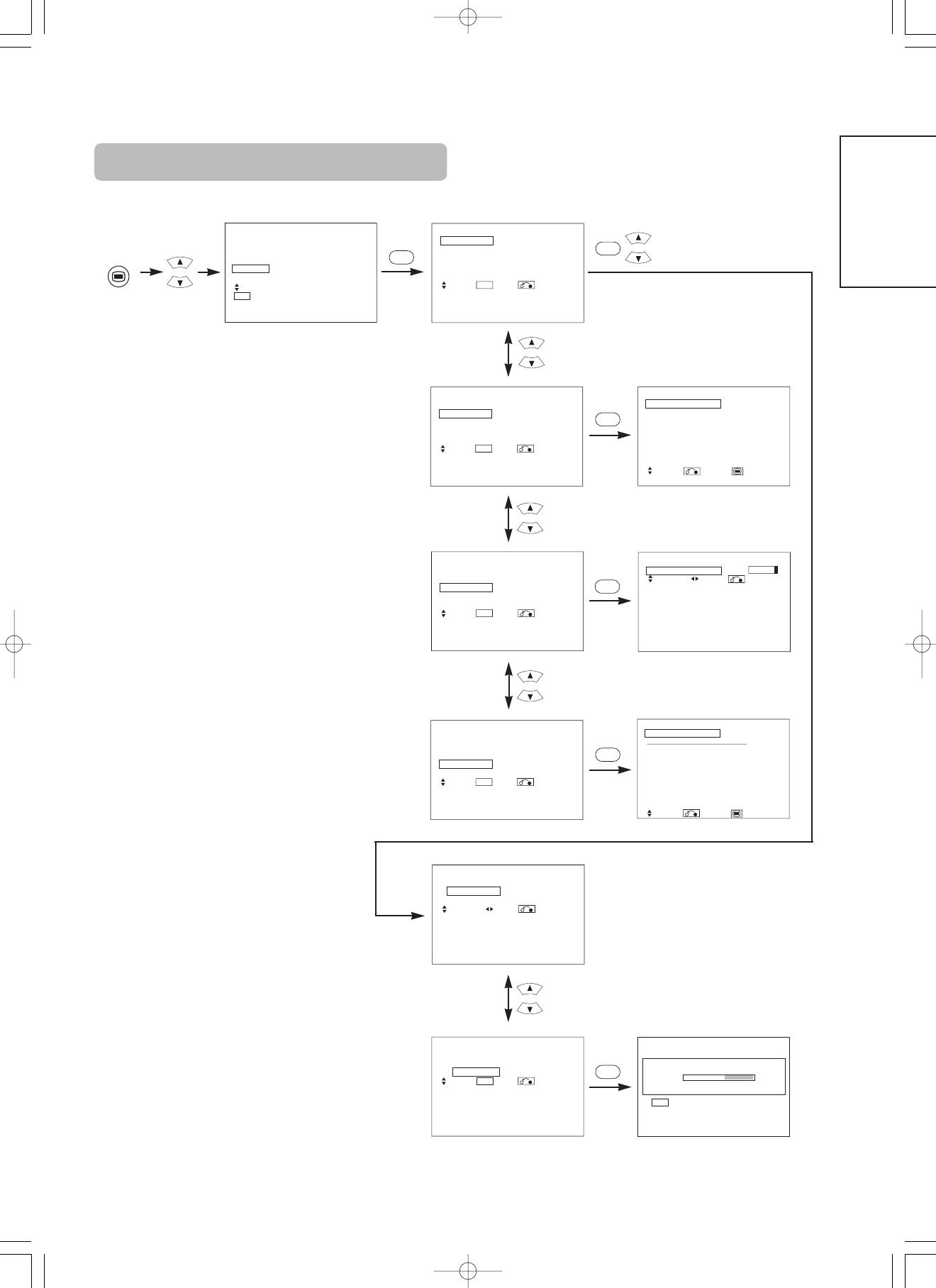
SETUP MENU
Picture
Audio
Timer
Function
Setup
Language
Select
OK Set
Setup
Auto Tuning
Manual Tuning
Fine Tuning
Sort
Auto Off Off
Select Set Return
OK
OK
MENU
Setup
Auto Tuning
Mode Position
Search
Select Set Return
OK
Setup
Auto Tuning
Mode Position
Search
Select Set Return
Setup
Auto Tuning
Scanning Channel Number: 33
Cancel
OK
Cancel
Setup
Auto Tuning
Manual Tuning
Fine Tuning
Sort
Auto Off Off
Select Set Return
OK
Setup
Auto Tuning
Manual Tuning
Fine Tuning
Sort
Auto Off Off
Select Set Return
OK
Setup
Auto Tuning
Manual Tuning
Fine Tuning
Sort
Auto Off Off
Select Set Return
OK
Setup
Manual Tuning
Position 99
Frequency 250MHz
Name ABCDE
Sound System BG
Color System Auto
Skip Off
NR Off
Select Return Exit
Setup Prog.No.199
Fine Tuning +56
Select Adjust Return
Setup
Sort
Position Name MHz
100 ABCDE 62MHz
101 BBC1 83MHz
102 ----- 97MHz
103 BBC 106MHz
104 FGHIJ 175MHz
105 XYZAB 189MHz
106 ----- 199MHz
107 ----- 225MHz
Select Return Exit
OK
OK
OK
OK
OK
[During TV mode]
Selected charactersSetup hint
Scart Output
TV Monitor
TV:AV4 (Scart) output will be fixed as TV signal output.
Monitor:AV4 (Scart) output can view the image as on the main unit.
But it is possible to monitor only the composite video signal from
AV1, AV2, or AV3 input that is displayed on the screen at the time.
OPERATING INSTRUCTIONS (continued)
SETUP MENU (continued)
Selected charactersSetup hint
Auto Tuning
Mode
Position Direct
Select the channel entry method between position setting or direct
setting. And press the OK button to fix it.
• If [Position] is selected, the screen display will be numbers (1~199
and AV00).
• If [Direct] is selected, the screen display will be C
✱✱
at the channel
0~99 and S
✱✱
at the channel 100~199.
Search
––
Press the OK button and it starts the auto tuning.
Manual Tuning
Position
––
Set the position number(0~199) or channel number(C
✱✱
, S
✱✱
) by
▼
▲
PROGRAM UP/DOWN buttons.
Frequency
––
• If [Position] has been selected, search the frequency here by
pressing buttons.
• If [Direct] has been selected, this function will be not available
(grayed out).
Name
( :a letter)
This is used to input the name of the TV station within 5 letters. After
fixing the cursor on the first digit, select a letter by
▼
▲
SELECT
buttons and move to next digit by ADJUST button. Press the OK
button again after finished.
• Selectable letters are “0”~`”9”, ”A”~`”Z”, “+”, “–”, ” ”(blank),
”,”(comma) and ”.”(period) .
Sound System
Auto M BG
DK I
Select the sound system through the 5 different settings.
Color System
Auto PAL SECAM
NTSC3.58 NTSC4.43
Select the color system through the 5 different settings.
Skip
Off On
If this is set to On, that position will be skipped while selecting
positions by PROGRAM UP/DOWN buttons.
This is automatically set to On for those non-broadcasting channels.
NR
Off On
If this is set to On, it helps to reduce the noise interference visible on
the screen, especially in the weaker signal reception areas.
Fine Tuning
Decreasing the frequency
data for the main tuner
Increasing the frequency
data for the main tuner.
After completing the fine-tuning, press the RETURN button to exit this
mode.
• The variable range is -56 ~ +56.
Sort
(When the Mode in Auto Tuning menu is set to [Direct], this function will be not available (grayed out).)
(A Line of position List)
––
Press OK button at the a line that is required to change order, then
the characters will change to green. And move it up or down in the list
by pressing
▼
▲
SELECT buttons. And press OK button to complete
it. Press the RETURN button to exit.
Auto Off
Off On
If this is set to On, the power will be turned off when there is no
transmission signal and no operation for about 10 minutes in the TV
mode.
[During VIDEO signal input]
1 item is added to the Menu shown in the page .
▼
▼
ENGLISH
OTHER FUNCTIONS
A2 / NICAM / Sound Multiplex
• The CH I / II button is only useful for NICAM and sound multiplex signals.
Otherwise pressing this button will have no effect.
BILINGUAL / DUAL sound broadcast
When bilingual program is received, sound mode display appears in yellow as shown on
right.
Press the CH I / II button to select the sound to be heard.
Each time the button is pressed, I, II or
▼
(force mono) appear cyclically on the screen.
When receiving NICAM signals, NICAM display will appear as below.
8
NICAM [II]
[I]
[II]
NICAM [I]
NICAM [II]
Sound multiplex signal received
Select I, II or (force mono) to hear the CH I, CH II or MONO broadcast respectively.
NICAM signal received
Yellow
YellowYellow
Yellow
Green
Green
NICAM
Sound multiplex signal received
Select or (force mono) to hear the STEREO or MONO broadcast respectively.
NICAM signal received
RedGreen
Red
Green
8
STEREO sound broadcast
When a stereo program is received, sound mode display will appear in red, and you can
press the CH I / II button to select between stereo and mono sound.
Each time the button is pressed,or
▼
(force mono)appear cyclically on the screen.
When receiving NICAM signals, NICAM display will appear as below.
Monaural sound broadcast
When a monaural program is received, sound mode display will appear in green.
You can press the CH I / II button to select the sound mode between monaural and forced
mono (sound is same).
Each time the button is pressed, or
▼
(force mono) appear cyclically on the screen.
NOTE
If sound signal is not strong enough for quality reception, press the CH I / II button until
▼
appears on the screen to receive a clear mono sound.
If sound has hiss noise or keep switching between stereo and mono mode due to signal condition, press the CH I / II button until
▼
appears
on the screen to receive a clear mono sound.
8
OPERATING INSTRUCTIONS (continued)
DVD Player Selection
• You can use this remote control to operate the selected brand of DVD player by pressing the following buttons on the remote control
simultaneously.
Example
To operate HITACHI DVD player, press and hold the RECALL button, followed by thebutton.
1
NOTE
Not all models of the listed brands can be operated using this remote control.
Brands of DVD PlayerPressBrands of DVD PlayerPress
HitachiRCA
PioneerMitsubishi
PanasonicOnkyo
ToshibaZenith
PhilipsOrion
JVCShinco
SamsungSkyworth
SonyBubuko
RECALL
1
RECALL
2
RECALL
3
RECALL
4
RECALL
5
RECALL
6
RECALL
7
RECALL
8
RECALL
9
RECALL
0
RECALLINDEX
RECALLMODE
RECALLSUB PAGE
RECALLCANCEL
RECALLREVEAL
RECALLTV/TEXT
D / N
A / B
i
+
MENU
OK
FREEZE
ZOOM
AV1
RGB1RGB2
AV2AV 3AV 4
2-4-12
I / II
P+
P-
+-
DVD
123
456
78
0
9
RECALL button
TV / TEXT button
MODE button
REVEAL button
INDEX button
SUB PAGE buttons
CANCEL button
OTHER FUNCTIONS (continued)
ENGLISH
Make the checks suggested below depending on the symptoms observed. If the symptoms remain uncorrected, contact your dealer.
Customer servicing can be hazardous.
WARNING
TROUBLESHOOTING
Symptoms That Seemingly Appear to be Failures
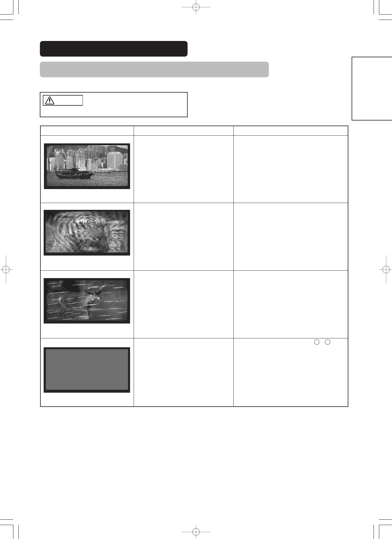
SymptomPossible reasonRemedy
(1) Connection of antenna cable to the TV is
poor.
(2) Corroded or poor antenna connections.
(3) Antenna has moved position.
(4) Adverse weather conditions.
(5) Transmitter problems.
(1) Make new connection and/or change antenna
plug.
(2) Make new connections or renew cable.
(3) Re-align antenna.
(4) None.
(5) Check with local Operator.
(1) Antenna has moved position.
(2) TV not tuned correctly.
(3) Adverse weather conditions.
(4) Transmitter problems.
(5) AV Input not set correctly.
(1) Re-align antenna.
(2) Re-tune or fine tune TV.
(3) None.
(4) Check with local Operator.
(5) Check the external equipment connected.
(1) Interference from electrical or mechanical
motors, fluorescent lights, portable
radios etc.
(1) Check devices for shielding and renew if
necessary or move further from TV.
(1) TV may be in AV mode.
(2) Picture/sound setting set to minimum.
(3) TV in standby or power save mode.
(1) Press the INPUT SELECT button or to buttons
on your remote control to return to normal TV
mode.
(2) Check picture / sound controls (go to MAIN
MENU).
(3) Press POWER ON / OFF button.
0
9
snowy picture - poor sound
multiple images - sound O.K
intermittent interference
no picture or sound
This table shows the specifications when the optional video unit and tuner unit have been inserted.
PRODUCT SPECIFICATIONS
• The monitor takes at least 30 minutes to attain the status of optimal picture quality.
Panel
Display
dimensions
Approx. 37 inches (814 (H) x 445 (V) mm, diagonal 930mm)Approx. 55 inches (1229 (H) x 691 (V) mm, diagonal 1410mm)
Resolution
1024 (H) x 1024 (V) pixels1366 (H) x 768 (V) pixels
Net dimensions
(excluding Speakers/Stand)
940 (W) x 573 (H) x 99 (D) mm1394 (W) x 857 (H) x 105 (D) mm
Net weight
(excluding Speakers/Stand)
29.0kg63.5kg
Ambient
conditions
Temperature
Operating : 5˚C to 35˚C, Storage : 0˚C to 40˚C
Relative humidity
Operating : 20% to 80%, Storage : 20% to 90% (non-condensing)
Libble takes abuse of its services very seriously. We're committed to dealing with such abuse according to the laws in your country of residence. When you submit a report, we'll investigate it and take the appropriate action. We'll get back to you only if we require additional details or have more information to share.
Product:
Forumrules
To achieve meaningful questions, we apply the following rules:
First, read the manual;
Check if your question has been asked previously;
Try to ask your question as clearly as possible;
Did you already try to solve the problem? Please mention this;
Is your problem solved by a visitor then let him/her know in this forum;
To give a response to a question or answer, do not use this form but click on the button 'reply to this question';
Your question will be posted here and emailed to our subscribers. Therefore, avoid filling in personal details.
Register
Register getting emails for Hitachi CMP5500 at:
new questions and answers
new manuals
You will receive an email to register for one or both of the options.
Get your user manual by e-mail
Enter your email address to receive the manual of Hitachi CMP5500 in the language / languages: English as an attachment in your email.
The manual is 1,36 mb in size.
You will receive the manual in your email within minutes. If you have not received an email, then probably have entered the wrong email address or your mailbox is too full. In addition, it may be that your ISP may have a maximum size for emails to receive.
The manual is sent by email. Check your email
If you have not received an email with the manual within fifteen minutes, it may be that you have a entered a wrong email address or that your ISP has set a maximum size to receive email that is smaller than the size of the manual.
The email address you have provided is not correct.
Please check the email address and correct it.
Your question is posted on this page
Would you like to receive an email when new answers and questions are posted? Please enter your email address.