629326
70
Zoom out
Zoom in
Previous page
1/88
Next page
1
DS-7204HVI-S Series Net DVR
User Manual
(V2.0)
Thank you for purchasing Hikvision Net DVR. This manual applies to DS-7204HVI-S Series
Net DVR. Please read it carefully for the better use of the product.
The contents in this manual are subject to change without notice. Hikvision assumes no
responsibility for inaccuracies or omissions and specifically disclaims any losses, or risks incurred
as a consequence, directly or indirectly, of the use of any of the contents of this manual.
Further information can be found on the following website: www.hikvision.com.
2
Index
Chapter1 Product Introduction...................................................................................................... 4
1.1 Overview ....................................................................................................................... 4
1.2 Model Description ......................................................................................................... 4
1.3 Features ......................................................................................................................... 4
Chapter2 Installation ..................................................................................................................... 6
2.1 Checking the DVR and Its Accessories ......................................................................... 6
2.2 HDD Installation ........................................................................................................... 6
2.3 Rear Panel Description .................................................................................................. 7
Chapter3 Operating Instructions ................................................................................................... 8
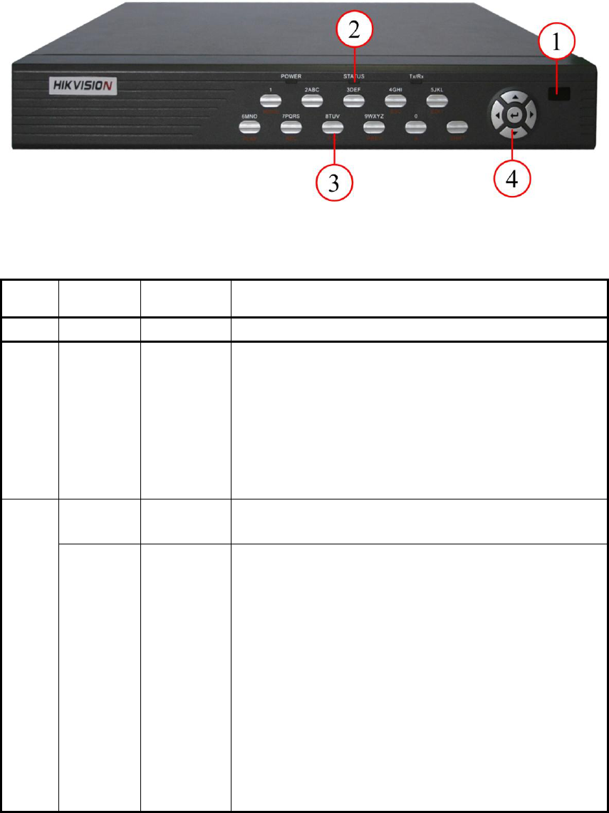
3.1 Front Panel Introduction ............................................................................................... 8
3.2 IR remote control .......................................................................................................... 9
3.3 Menu Description ........................................................................................................ 11
3.3.1 Menu Items ..................................................................................................... 11
3.3.2 Menu Operation .............................................................................................. 12
3.4 Input Text .................................................................................................................... 15
Chapter4 Basic Operation Guide ................................................................................................ 16
4.1 Power on ................................................................................................................... 16
4.2 Preview...................................................................................................................... 16
4.3 Video Spot Output ..................................................................................................... 19
4.4 User name and Password .......................................................................................... 19
4.5 PTZ Control .............................................................................................................. 21
4.6 Manual Record .......................................................................................................... 24
4.7 Playback .................................................................................................................... 25
4.8 Backup Recorded Files ............................................................................................. 28
4.9 Shut down DVR ........................................................................................................ 29
Chapter5 Parameters Setup Guide .............................................................................................. 30
5.1 Administrator and Password ....................................................................................... 30
5.2 Add and Delete User ................................................................................................... 32
5.3 Unit Name and Device ID ........................................................................................... 35
5.4 Video Output Standard ................................................................................................ 37
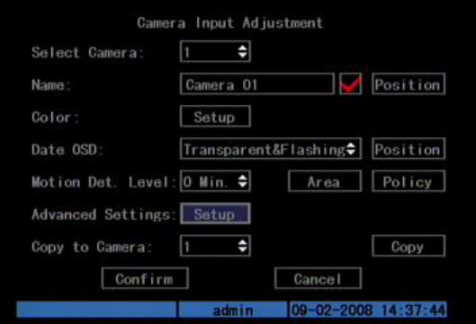
5.5 Camera name and OSD Setup ..................................................................................... 38
5.6 Video Parameters Setup .............................................................................................. 41
5.7 Mask Area Setup ......................................................................................................... 42
5.8 View Tampering Alarm ............................................................................................... 44
5.9 Video Loss Alarm ........................................................................................................ 46
5.10 Motion Detection ........................................................................................................ 48
5.11 Preview........................................................................................................................ 50
5.12 Recording Setup .......................................................................................................... 51
5.13 External Alarm Input and Relay Output ...................................................................... 55
5.14 Network Parameters .................................................................................................... 60
5.15 PTZ ............................................................................................................................. 62
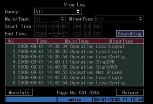
Chapter6 Utilities ........................................................................................................................ 67
3
6.1 Restore Parameters .................................................................................................... 67
6.2 Upgrade ..................................................................................................................... 68
6.3 Hard Disk Management ............................................................................................ 69
6.4 Stop Alarm Out ......................................................................................................... 69
6.5 Reboot ....................................................................................................................... 69
6.6 Power off ................................................................................................................... 69
6.7 View Log ................................................................................................................... 69
6.8 System Information ................................................................................................... 73
Chapter7 Firmware Upgrade ...................................................................................................... 74
7.1 Upgrade Mode ........................................................................................................... 74
7.2 FTP Server Setup ...................................................................................................... 74
Appendix A Mouse Control Function ............................................................................................. 79
Appendix B HDD Capacity Calculation ......................................................................................... 81
Appendix C DVR Connect Cable Definition .................................................................................. 82
Appendix D Specifications .............................................................................................................. 84
Appendix E Troubleshooting .......................................................................................................... 85
Appendix F Product Service ........................................................................................................... 87
Appendix G Customer Information Card ........................................................................................ 88
4
Chapter1 Product Introduction
1.1 Overview
DS-7204HVI-S series network digital video recorder is an excellent digital
surveillance product. It uses the embedded MCU and Linux, combining the most
advanced technology in the information industry, such as video and audio
encoding/decoding, hard disk recording and TCP/IP. The firmware is burned into the
flash, making it more stable and reliable.
DS-7204HVI-S series device has the features of both digital video recorder
(DVR) and digital video server (DVS). It can be used as a standalone device but also
to build a powerful surveillance network which is widely used in the fields of banking,
telecommunications, transportation sectors, manufacturing, warehouse, irrigation, etc.
1.2 Model Description
1.3 Features
Compression
H.264 video compression algorithm and each channel can be CIF real-time
(PAL: 25FPS, NTSC: 30FPS), and 4CIF, DCIF, 2CIF and QCIF can be selected
as well.
Support multi-area motion detection
Support Privacy Mask
Support view tampering alarm
DS 72 04 H V I -S
Support SATA HD
Oversea products
High Definition Version
Model name
Camera Number
Embedded Net DVR series
Digital Surveillance
5
Support video signal loss alarm
Support changeable OSD position, support LOGO.
Support both variable bit rate and frame rate.
Support dual-stream, and the sub stream can support CIF/QCIF resolution.
Storage:
One SATA interface and the HDD can support up to 2000GB memory.
HDD S.M.A.R.T. technology
Support FAT32 file system
Support multiple record modes: schedule record, motion detection record,
external alarm record, motion & alarm record, motion or alarm record, manual
record.
Support cycle and none cycle record mode.
Support USB flash disk, USB hard disk and USB CD/DVD-R/W to backup.
Preview & Playback:
Support one main video output and one spot video output.
DS-7204HVI-S can support one VGA output with 1024*768 resolution.
Support VGA and VOUT output, VGA has precedence over VOUT, and can
not output at the same time.
Support play forward, backward, pause, frame-by-frame, etc.
User-defined preview layout.
Support one playback channel.
Network:
Support TCP, UTP, RTP, Multicast, DHCP, etc.
DS-7204HVI-S supports RTP.
Support ADSL (PPPoE) dialup function.
Remote parameters setup
Remote download and playback the recorded files.
Remote upgrade the DVR firmware
Remote PTZ control
Support IE for network control
Remote alarm DVR information acquisition
Others:
Support network voice talk.
Support WATER MARK
Support local and remote PTZ control.
Support multi-level user management.
Support local and remote log searching function.
Automatically recovery from exceptions enables high reliable.
Provide SDK and demo source code for application development.
6
Chapter2 Installation
Warning: Before you install the DVR, please make sure that the power of DVR is
switched off.
2.1 Checking the DVR and Its Accessories
When you get the product, check that all the goods are included in your product
package. There is a list in the package. If any of the goods is missing, please contact
your dealer.
2.2 HDD Installation
Installation notice
Note: A factory recommended HDD should be used for this device.
There is no HDD in the DVR when leaving factory. According to the record
schedule, you can calculate the total capacity you need (refer to Appendix A). Please
ask the specialist to disassemble the DVR and install HDD.
Installation instrument
One cross screw driver
HDD installation
1. Open the DVR box.
2. Place the HDD on the mounting plate.
3. Connect the ATA data cable correctly. First put the power plug of the HDD in
the motherboard. Plug the data line of the HDD into the SATA interface.
4. Fix the HDD into the Chassis.
5. Cover and fix the DVR box.
Note: After the HDD installation, you must format them. Please refer to section
6.3.
7
2.3 Rear Panel Description
Fig. 2.1 DS-7204HVI-S Rear panel
Note: Please refer to real product for different models.
DS-7204HVI-S
Video in Video out VGA interface
Alarm out RS-485 T+ T- R+ R- Power switch
USB interface Audio in Audio out
UTP interface
12 Alarm in
13 +12V DC power supply
input
8
Chapter3 Operating Instructions
3.1 Front Panel Introduction
Fig. 3.1 Front panel introduction
Table 3.1 Items on front panel
Index
Type
Name
1
Lamp
2
State
Lamps
Power
STATUS
Tx/Rx
3
Numeric
Keys
Function
Keys
MENU
2
3
ESC
EDIT
PLAY
REC
9
PTZ
PREV
A
SHIFT
4
Control
Keys
Direction
Keys
ENTER
3.2 IR remote control
Fig. 3.2 Elevation of IR remote control
10
Table 3.2 Instruction of IR remote control
Index
Name
Description
1
POWER
Turnoff device.
2
DEV
Enable IR remote control.
3
Numeric Keys
Same as numeric keys of front panel.
4
EDIT
Same as EDIT key of front panel.
5
A
Same as A key of front panel.
6
REC
Same as REC key of front panel.
7
PLAY
Same as PLAY key of front panel.
8
Reserved
-
9
Reserved
-
10
MENU
Same as MENU key of front panel.
11
PREV
Same as PREV key of front panel.
12
Direction Keys
ENTER
Same as direction keys and enter key
of front panel.
13
PTZ
Same PTZ key of front panel.
14
ESC
Same as ESC key of front panel.
15
Reserved
-
16
F1
Key for Extension.
17
Lens control
IRIS, FOCUS ZOOM for lens
control.
18
F2
Key for spot video output.
Placing the batteries into the IR remote control
1. Remove the battery cover.
2. Insert the battery. Please make sure that the poles (+ and -) are correctly placed.
3. Fold the battery cover.
Start to use IR remote control
Switch the device power on, wait without any operations until preview screen
appears, and then you can use IR remote control to manage DVR on condition that the
device ID is default “255”, which can be changed in “Display” menu.
If the default device ID has been changed, please press [Power] & [DEV] key of
IR remote control, input the present device ID and then press [ENTER] key. Then you
can use IR remote control to operate this DVR.
11
Stop using IR remote control
When DVR controlled by IR remote control, press [DEV] key again, then the IR
remote control can not control this DVR.
Switch the DVR off
When IR remote control is working, press [POWER] key for several seconds,
then the power off prompt will pop up, press [Confirm] and switch off the power on
the rear panel manually.
When IR remote control can not work normally
Check batteries poles.
Check the remaining charge in the batteries.
Check IR remote control sensor is masked.
Please change another IR remote control and try again. If the problem still exists,
please contact administrator.
3.3 Menu Description
3.3.1 Menu Items
Table 3.3 First Glance at menu
Menu Name
Function
Menu
Name
Function
Display
Device ID
Require password
Screen saver
Video standard
Enable scaler
Menu transparency
Date/Time
Preview
Camera
Select camera
Name
Color
Date OSD
Motion Det. Level
Advanced Settings
Recording
If HD Full
Select camera
Stream type
Resolution
Frame rate
Bit rate
Enable Rec
PreRec time
PostRec time
Network
IP
Port
Mask
Gateway
Http Port
Advanced Settings
PPPoE
12
Alarms
Select Alarm In & Alarm Type
Alarm Handling & policy & PTZ
linkage
Alarm out & time
Exceptions
PTZ
Select Camera
Baud Rate & Data Bits
Stop Bits & Protocol
PTZ Add. & Preset
Sequence No. &
Cruise
User
Add/Delete
Password/Verify
Default Privileges
Set Privileges
Utilities
Default parameters
Firmware
Hard Disk
Alarm output
Reboot
Power off
View log
System information
3.3.2 Menu Operation
How to enter the menu mode
Press [MENU] key to enter the DVR main menu.
Press [PLAY] short key to enter the playback menu.
Press [REC] short key to enter the manual record menu.
Press [PTZ] short key to enter the PTZ control interface.
Note: You must input user name and password. The default user name is
“admin” and password is “12345”.
Main Menu Description
The main menu interface is shown as Fig.3.3 below:
Fig. 3.3 Main menu
13
There is one small frame named “Active Frame”. It can be moved from one item to
another by using direction keys ([][]). When the “Active Frame” is located on one
icon, you can press [ENTER] key to enter the sub menu. For example, move the
“Active Frame” to Cameraicon, press [ENTER] to enter the sub menu as follows
Fig.3.4 below:
Fig. 3.4 Camera input adjustment
Each menu contains different kinds of items. There is a small rectangular frame
named “Active Frame” which is pointing to the selected item. This “Active Frame”
can be moved by direction keys ([][][][]). There are several kinds of menu items
as follows:
1. Check Box: Provides two options, “means enable and “×” means disable.
You can use [ENTER] or [EDIT] key to switch over.
2. List Box: Provide more than 2 options. Only one of them can be selected.
After pressing [EDIT] you can use [] and [] to select one option. For
example, on the right side of “Select Camera”, there is a list box for you to
select one camera.
3. Edit Box: This is for you to input characters. Press[EDIT]key to enter the
edit status, you can input text there:
a) Press[A]key to select number, upper case, lower case or symbols;
b) Use[]and[]keys to move cursor;
c) Use[EDIT]key to delete the character in front of cursor;
d) Press [ENTER] to save & [ESC] to exit without saving.
4. Button: Trigger a special function or enter the next sub-menu. For example,
press “Policy” button to enter the sub-menu. Press [Confirm] to save
parameters and return to main menu. Press [Cancel] button to cancel and
return to main menu. The button in grey means it can be operated only after
being enabled.
14
How to exit menu
Press [ESC] key to exit menu and return to preview mode.
15
3.4 Input Text
In the menu interface, if in edit status (for example, in the “camera name” edit
box), at the bottom of screen, the input status is appeared as follow:
Here it means you can press numeric keys to input digital number.
Press [A] key to change input ways. You can select “Number”, “Uppercase”,
“Lowercase” or “Symbol”.
Uppercase
Lowercase
Symbol
There are 24 symbols in all. They are divided into 4 pages, and you can press [0] key
to turn over pages.
16
Chapter4 Basic Operation Guide
4.1 Power on
Note: Please make sure that the power supply matches DVR and AC adapter
is connected correctly. Before switching DVR on, please connect one monitor
through VOUT or VGA interface. Otherwise, you can not see graphic user
interface and operate the device.
If [POWER] lamp is off, please follow the steps below:
Step1: Connect power supply correctly;
Step2: Switch on the power button on the rear panel.
When DVR is started,[POWER]lamp is green. If the HDD is not installed or
detected, the information “No Disk A ×will be seen in the lower right corner of the
preview screen.
4.2 Preview
DVR will enter the preview mode after started.
On preview screen, you can see date, time, and camera icon.
Set system date and time in “Camera” “Date OSD” menu, please refer to 5.5;
Change camera name in “Camera” menu, please refer to 5.5
On the screen, you will see record and alarm status of each camera. Shown as
Fig.4.1 below, these two kinds of status will alternate automatically.
Press [A] key to display or hide the camera status bar.
Fig. 4.1 Recording Status
17
Table 4.1 Camera record Status
Icon
Icon Color
Status Description
White
No video signal
Yellow
Video input
Pink
Manual recording
Green
Real time recording
Blue
Motion detect recording
Red
External alarm recording
Fig. 4.2 Alarm status
Table 4.2 Camera alarm status
Icon
Icon Color
Status Description
White
Video signal loss
Yellow
View tampering alarm
Pink
Motion & External alarm
18
Green
No alarm
Blue
Motion alarm
Red
External alarm
Press numeric keys to switch individual camera preview in SHIFT mode. For
example, you can press [2] key to preview 2
nd
camera.
Press [EDIT] key to manual cycle preview. You can set the auto preview mode in
“Preview” menu, referring to 5.11.
Press [PREV] key to switch multi-screens preview.
19
4.3 Video Spot Output
Make sure that the numeric button is in “function” mode (the status lamp is off)
Press [shift] button to switch numeric button between “numeric” mode and “function”
mode.
Step1: Connect Video out 2 with monitor by a cable.
Step2: Press [3] to enter the spot out mode.
Step3: Press [shift] to enter the numeric mode.
Step4: Press [1] to [4] button to switch video spot output from channel 1 to
channel 4.
Note: make sure that there is video signal input; otherwise spot out will be only
shown as blue screen.
4.4 User name and Password
Note: When DVR is delivered from factory, there is only one default
administrator named “admin”, and password is “12345”. The administrator’s
name can not be modified, while the password can be modified. The
administrator can create 15 users and define their rights.
Login
Login dialog as shown Fig.4.3 below
Fig. 4.3 Login dialog
Use []/ [] keys to select one user, press [] key to enter “Password” edit box,
input corresponding password, press [ENTER] key to exit edit box. The “Active
Frame” will move to “Confirm” button. You can press [ENTER] key to enter main
menu. If there is no response, it means the user name and password are not matched.
After three error times, DVR will enter the preview mode.
20
Modify password
For those users created by admin, they can modify their passwords as follows:
Step1: Enter main menu
Press [MENU] key, in the login dialog, select your user name, input the correct
password, you can enter the main menu. As shown Fig.4.4 below.
Fig. 4.4 Input passwords
The main menu shown as Fig.4.5
Fig. 4.5 Main menu
Step 2: Select the target user name by using [],[] then move the “Active
Frame” to “Password” icon by using[]/[]keys. As shown in Fig.4.6 below.
21
Fig. 4.6 Modify users password
Step 3: Input new password
Use numeric keys to input new password. The password can be null. It also can
be 16 numerals. Press [ENTER] to exit edit box, and move to “Verify” item to verify
password.
Note: In edit box, use []/ [] to move cursor and [EDIT] key to delete the
numeral in front of the cursor.
Step 4: Modify password successfully
Move the “Active Frame” to “Confirm” button, press [ENTER] key. If the
password is modified successfully, you will turn to the main menu. Or an error dialog
will pop up. You can repeat step 3 to modify again.
4.5 PTZ Control
Note: The user must have the “PTZ control” right.
PTZ control interface
In menu mode, press [PTZ] key, you can enter the PTZ control interface directly.
In preview mode, press [PTZ] key, in the login dialog, select one user name and
input the correct password, you can enter PTZ control interface. As shown in Fig.4.7
below.
22
Fig. 4.7 PTZ Control interface
The position where current camera name displays can be user-defined.
Select channel
In PTZ control mode, you can press numeric keys under SHIFT mode to select
channel. For example, you can press [2] key to select the 2
nd
camera PTZ.
After you select the camera PTZ, you can use the control keys to control PTZ.
PTZ control keys description
Direction control keys: [], [], [], [].
ZOOM control keys: [2] for ZOOM-, [3] for ZOOM+.
FOCUS control keys: [A] for FOCUS+, [PRE] for FOCUS-.
IRIS control keys: [EDIT] for IRIS+, [PTZ] for IRIS-.
Adjust preset keys: [REC/SHOT].
Auto control key: [PLAY/AUTO].
Wiper control key: [MENU/WIPER].
Adjust preset description
In PTZ control mode, press [REC/SHOT] key, and press the preset number (three
numeric keys); DVR will adjust the corresponding preset number. Repeat pressing
[REC/SHOT] key, and press the preset number, DVR will adjust that preset number.
When you exit PTZ control mode, the camera will stay at the current position.
Note: The PTZ preset number has been set already. Please refer to PTZ
menu for preset setup. V2.0 firmware can support 128 preset at most.
Start/Stop auto function in PTZ control mode
23
In PTZ control mode, press [PLAY/AUTO] key to start PTZ auto function. Press
[PLAY/AUTO] key again to stop.
When PTZ is in auto mode, if you exit PTZ control mode, PTZ will continue
auto function unless you enter the PTZ control mode again, and press [PLAY/AUTO]
key to stop.
Exit PTZ control mode
Press [ESC] or [ENTER] to exit and return to the preview mode.
24
4.6 Manual Record
Note: The user must have the corresponding right, DVR has HDD and HDD has
been formatted already.
Manual record
In preview mode, press [REC] key, in the pop-up login dialog, select the name
and input the correct password, you can enter the “Manual Record” interface.
In menu mode, press [REC] key to enter the “Manual Record” interface directly.
Fig. 4.8 Manual record interface
Description
Manual record interface has follows parts: channel number, channel status,
start/stop record, start all and stop all buttons.
Channel: List the channel number DVR has.
Status: Channel work status has 4 cases: means idle. Green means the
channel is recording (including real time recording, alarm recording, motion detection
recording). Red means network transmission. Orange means both recording and
network transmission.
Start/Stop: means you can start corresponding channel recording. “×”
means you can stop recording.
Start All: Press this button to start all channels recording.
Stop All: Press this button to stop all channel recording.
Press [ESC] key to enter the preview mode. Press [MENU] key to enter main
menu. Press [PLAY] key to enter the playback menu. Press [PTZ] key to enter the
25
PTZ control mode.
4.7 Playback
Note: The user must have “Playback” right.
Playback interface
In preview mode, press [PLAY] key, in the pop-up login dialog, select user name
and input correct password, you can enter the “Playback” interface.
In menu mode, press [PLAY] key, you can enter the “Playback” interface directly.
Shown as Fig.4.9 below.
Fig. 4.9 Playback interface
Description
Select a Channel: Move the “Active Frame” to “chan”, press “edit” button, then
use [] or [] key to select a channel.
Rec Type: Use [] or [] to select recorded files type. The file type options have
“All”, “All Time”, “Motion Detect”, “Alarm” and “Manual”.
Time Section: You can define the search time section. Move “Active Frame” to
the time edit box, use numeric keys to input the detail time.
Search: Search the matched recorded files and display them in the list box. If
there is not matched file, a corresponding dialog box will be pop-up.
Play by Time: Playback the recorded stream directly based on the time section.
Select Page: In the file list box, each page will only display 8 files. If the
matched files are more than 8, you can select page to list other files. 500 pages (4000
files) can be searched in one time. You can use numeric keys or [] [] keys to select
page.
File List Box: List the matched files. File started time, file size are displayed in
the list box. You can use [] [] keys to move the scroll bar to select file.
26
Backup Devices: You can select USB flash, USB HDD, USB CD/DVD-R/W to
backup the files or clips.
Copy: Start to backup.
Backup Today: Backup all recorded files of today.
Operation when playback
Fig. 4.10 Playback interface
At the bottom of image, there is an information bar and the following
information is included: Volume, Play Progress, Play Speed, Played Time and File
Total Time.
Display/Hide information bar: [MENU]
Open/Close sound: [PLAY]
Adjust play progress: [] (Backward), [] (Forward). The unit is “%”.
Adjust play speed: Normal speed is “1x”. Use [] to increase play speed (2X,
4X). Use [] to decrease play speed (1/2X, 1/4X, 1/8X and single)
Pause/Continue: Press [ENTER] to pause/continue playback. If played frame by
frame, Press [ENTER] to play one frame.
Copy segment: [EDIT]; Stop copy: [EDIT] (Need a back up device to store the
segment)
Exit: [ESC]
Note: When DVR is busy, if you select high play speed, maybe there is
difference from actual play speed.
Exit playback
In playback interface, press [ESC] key to enter the preview mode.
Playback with mouse plugged
If you playback with a mouse plugged, they interface will be a little different.
And you can acquire more functions to operate in the playback course which is shown
27
as Fig.4.11 below.
Fig. 4.11 Play back control bar
There is an additional bar appears. We call it control bar.
Control bar descriptions:
: You can click these buttons to skip backward or
forward 30s each time.
: You can click these buttons to select the play speed.
: Click this button to pause.
: Click this button to be mute, click it again to recover
the sound.
: Click this button to start copy the segment, click it
again to stop.
: Click this button to hide the control bar, right click
your mouse and select display, then the control bar
will turn up again.
: Click this button will trigger a rectangle area on the
screen ,draw the rectangle with left key of your mouse
pressed and move to the area you want to zoom in
then double click left key to zoom in that place. Click
left key again to return to the playback interface.
: Click these buttons to switch to next or previous
playback channels. It is useless if you only record one channel at that time.
28
4.8 Backup Recorded Files
Note: The user must have “Playback” right. Please connect the backup
devices before you start to backup.
In the playback interface, you can backup the recorded files.
In the preview mode, press [PLAY] key, in the login dialog, select username and
input the correct password, you can enter the playback interface.
In the menu mode, just press [PLAY] key, you can enter the playback interface
directly.
Backup intraday recorded files
In the playback interface, move “Active Frame” to “Backup Today” button,
press[ENTER]key, all intraday recorded files of all channels will be backup to the
storage device. A pop-up dialog will display the backup status.
If backup device is not connected correctly or DVR do not detect the backup
device, an exception dialog will pop up. Please ask administrator for more
information.
Backup the files that matched your requirement
Step 1: Search the matched files
In the playback interface, select one channel and record type, input the time
section, move “Active Frame” to “Search” button, press[ENTER]key, DVR will start
to find and list the matched files.
Step 2: Select the files that you want to backup
In the file list box, use [] or [] keys to move the scroll bar. When the scroll bar
stays at the file you want to backup, press [EDIT] key to select it. The symbol is
the selection tag. You can use the same method to select other files you want to
backup. After finish, you can follow the next step. Shown as Fig.4.12 below
29
Fig. 4.12 Playback list
Step 3: Select backup device
Please confirm the backup device: USB flash memory, USB HDD, USB R/W
and select the corresponding backup device.
Step 4: Start and finish backup
Move “Active Frame” to “Save” button and press [ENTER] key to start backup.
When backup is started, corresponding message box will pop-up to indicate the
process.
Backup video segment
You can also backup the image segments when playback. The steps are:
1) Enter the interface of playback the files or playback by time;
2) Press [EDIT] key to start selecting the current playback image, and press
[EDIT] again to stop selecting. This segment is selected;
3) You can repeat step 2 to select many segments. 30 segments can be selected
in all;
4) After you select all segments, press [ESC] key, a message window will
pop-up. If you press “Confirm” button, DVR will start to backup the selected
segments. If you press “Cancel” button, DVR will abort backup.
Playback the video segment
You can use our file player software to playback the video segment in PC. You
can find the player software in attached CD.
Exit playback interface
Please refer to chapter 4.6.
4.9 Shut down DVR
Note: You can press [Power] button on the rear panel to turn off the power
directly; it won’t damage the DVR or HDD.
30
Chapter5 Parameters Setup Guide
Only the users who have “Parameters Setup” right need to read this chapter.
When the following parameters are modified and saved, you must reboot the DVR to
make the new parameters become effective. Others do not need to reboot the device.
Any network parameters
resolution and record schedule
External alarm sensor type
View tampering alarm schedule
Video loss alarm schedule
Motion detection alarm schedule
External alarm schedule
Alarm output schedule
5.1 Administrator and Password
When DVR is left from factory, there is one default administrator. The name is
“admin” and password is “12345”. The name can not be changed, while the password
can be modified.
Password modification
Press[MENU]key, in the login dialog, select the username as “admin”,
use[]key, move cursor to password edit box, input “12345”, press “Confirm” to
enter the administrator menu shown as Fig.5.1.
Fig. 5.1 Enter user menu
Move “Active Frame” to “User” icon, press [ENTER] key to enter “User
Management” menu. Shown as Fig.5.2 below
31
Fig. 5.2 User management
In the user name list box, only “admin” is existed. You can use [] key,
move “Active Frame” to password edit box, and press [EDIT] key to enter edit status.
Press numeric keys to input the new password. The password is only combined by 16
numerals at most. After finishing inputting password, you can press [ENTER] key to
exit. Move “Active Frame” to “Verify password” edit box, input the verify password.
Move “Active Frame” to “Confirm” button, and press [ENTER], if password and
verify password are the same, the password will be saved and taken into effective.
If password and verify password are not same, a warning message box will be
appeared. Shown as Fig.5.3 below
Fig. 5.3 Error
In this case, press [ENTER] to return password edit box, and input new password
again.
32
5.2 Add and Delete User
Enter “User Management” interface.
Add user
The steps are following:
Step 1: Enter “User Management” menu as Fig.5.4 below
Please refer to chapter 5.1
Fig. 5.4 user management
Step 2: Add new user name
In the “User Management” menu, move “Active Frame” to “Add” button and
press [ENTER], in the pop-up dialog, input the new user name (refer to chapter 3.4),
press [ENTER]and return “User Management” menu. Totally 15 users can be added.
Shown as Fig.5.5 below
Fig. 5.5 Input user name
33
Step 3: Setup the password for new user
After you add one new user, the password is null. You can skip this step if you do
not want to change the password.
In the users list box of “User Management” menu, use [] [] keys to select the
new user name, then use [] key to the password edit box. Press [EDIT] key to enter
edit box, use numeric keys to input the new password.
Step 4: Setup the rights for new user
The new added user has not any operational rights. You must setup rights for him.
In the users list box of “User Management” menu, use [] [] keys to select the
new user name, then use [] key to “Default Privilegesbutton, press [ENTER], the
user will have the default rights. The default rights include local playback, remote
playback and view log.
If you want to define the detail rights, move “Active Frame” to “Setup
Privilegesbutton and press [ENTER] to enter rights setup menu as follows: Shown
as Fig. 5.6
Fig. 5.6 Set user right
Operational rights are divided into “Local” and “Remote”. You can assign the
necessary rights to the user. Use [] [] key to move “Active Frame” to the
corresponding right items, press [ENTER] or [EDIT] key to enable or disable the item.
means assign the right to that user.
Step 5: Save the new users password and rights
In the “User Management” menu, press “Confirm” button, the users password
and rights will be saved and return main menu. If you press “Cancel” button, the
configuration will be abandoned.
User rights description
“Local”:
34
Local rights are for local operation, such as the operation using front panel, IR
remote control and RS-485 interface.
PTZ control: Locally control PTZ;
Record: Manual start/stop recording;
Set parameters Setup: Locally setup the DVR parameters;
Log: Locally view the log on DVR;
Utilities: Locally upgrade firmware, format HDD, reboot DVR and shut down
DVR, etc.
“Remote”:
PTZ Control: Remote control PTZ;
Record: Remote manual start/stop recording;
Set parameters Setup: Remote setup the DVR parameters;
Log: Remote view the log on DVR;
Utilities: Remote upgrade firmware, format HDD, reboot DVR and shut down
DVR, etc;
Talk: Client talks with DVR;
Alarm: Remote control DVR alarm output;
Local Video Out: Remote control DVR video output;
Com Control: DVR RS-485.
MAC address
This MAC address is not the address of DVR but the address of the PC that
accesses DVR. If you setup this function, only the PC with this MAC address can
access this DVR.
At PC end, in DOS prompt, you can use “ipconfig” command to get the PC MAC
address (6 bytes).
Delete user
In “User Management” interface, you can use [] [] keys to select one user,
then use [] to move “Active Frame” to “Del” button, press [ENTER], in the pop-up
confirmation dialog, press “Confirm” button to delete the selected user and return.
Press “Cancel” or [ESC] to abort deleting. Shown as Fig.5.7 below
35
Fig. 5.7 Delete user
5.3 Unit Name and Device ID
Unit name
Enter “Utilities” “System Info” and “Unit Name” will be seen as Fig.5.8
below:
Fig. 5.8 System Info
There is an item named “Unit Name”. The default unit name is “Embedded Net
DVR”. Move “Active Frame” to unit name edit box, press [EDIT] key to enter edit
status, you can modify the unit name. Please refer to chapter 3.4 about how to input
characters. You can press [ENTER] key to finish modification. Select “Confirm”
button and press [ENTER]; you can save the new unit name and make it into effect.
Press “Cancel” button or [ESC] key to abort modification.
36
Device ID:
Fig. 5.9 Display menu
When using IR remote control to operate DVR, you must use device ID to select
DVR. The default device ID of DVR is 255”. If there are more than one DVR in one
place, please define different device ID for each DVR. Otherwise, the IR remote
control will control all DVR with the same device ID at the same time.
In “Display” menu, move “Active Frame” to the device ID edit box, in the edit
status, you can use numeric keys to input new device ID. The device ID value is
ranged between 1-255.
After you finish the modification, press “Confirm” button to save and take effect
or press “Cancel” to abort modification.
37
5.4 Video Output Standard
Video output standard
There is one VOUT BNC connector at the rear panel of DVR. It is used to
connect with analog monitor and can support PAL or NTSC video output. You can
modify video output standard to match video input.
In “Display” menu: There is a list box named “Video Standard”, you can use []
[] key to select PAL or NTSC video output.
Press “Confirm” button to save or “Cancel” to abort.
38
5.5 Camera name and OSD Setup
Camera Name
In “Camera” menu, you can define name for each camera. Please notice that
camera’s name can not be copied. Shown as Fig.5.10 below.
Fig. 5.10 Input camera number
The steps of camera name setup:
Step 1: Select one camera.
Step 2: Move “Active Frame” to camera name edit box, press[EDIT]key to enter
edit status, you can input digital number, uppercase and lowercase characters (refer to
Chapter 3.4). The camera name can support 32 characters.
Step 3: Press [ENTER] key to exit edit status.
Move “Active Frame” to “Confirm” button, press [ENTER] to save the
modification and you can see the new camera name. Press “Cancel” button or [ESC]
key to abort.
Camera Name Position
If you do not want to display camera name, just disable the check box beside
camera name edit box. The disable flag is “×”. If you enable the check box, you can
setup the camera name position. You can copy the position to any other camera. The
setup steps are:
Step 1: Enter “Camera” menu.
Step 2: Select one camera.
Step 3: Enable the check box on the right side of camera name, then you move
“Active Frame” to “Position” button, press[ENTER]to enter camera name position
setup interface, as picture below in that interface, you can use[][][][]keys to
move camera name position. When the position is fixed, press [ENTER] and return
“Camera” menu, and press “Confirm” button to save it. In the “Image Setup” menu,
press “Cancel” button or [ESC] key, you can abort the modification.
OSD is abbreviation of “On Screen Display”. For our embedded DVRDVS, it
39
includes displaying system time and camera name.
OSD settings include: System time, time format, time display position, camera
name, camera name display position, etc.
System Time
In “Display” menu, you can setup DVR system date and time.
Move your active frame to “Date/Time setup” item, and press enter.
Date Display Mode: Move the active frame to Date Display Mode then press
[EDIT] then use [] [] key to select OSD format. There are following OSD formats:
MM DD YY
DD MM YY
YY MM DD
YY MM DD Here YY means year, MM means month, DD means day.
You can also enable DST (Daylight-saving Time) function here. Shown as
Fig.5.11 below.
Fig. 5.11 Date/time setup
Date OSD Position
In “Camera” menu you can adjust the position where you want Date to display,
move active frame to Position item on the right side of “Date OSD” item and press
enter button. Then you will see the picture below. Use [] [] [] [] to adjust the
position of date. As Shown:
70
In “Utilities” menu, press “View Log” to enter “Log” menu: Shown as Fig.6.6
below.
Fig. 6.6 View log
If you want to view the log based on default option, just press [ENTER] key. DVR
will list all matched information. Also you can select options to search (By Type, By
Date, and By Type & Date).
By Type
View log information by the assigned type.
Type is divided into “Major type” and “Minor type”. Major type includes
operation, alarm, exception and all.
For operation major type, there are many minor types, including Power On, Shut
Down, Abnormal Shut, Panel Login, Panel Logout, Panel Config, Panel File Play,
Panel Time Play, Local Start Record, Local Stop Record, Panel PTZ, Panel Preview,
Panel Set Time, Local Upgrade, Net Login, Net Logout, Net Start Record, Net Stop
Record, Net Start Transparent Channel, Net Stop Transparent Channel, Net Get
Parameter, Net Config, Net get Status, Net Alert On, Net Alert Off, Net Reboot,
BiComStart (Start Voice Talk), BiComStop (Stop Voice Talk), Net Upgrade, Net File
Play, Net Time Play, Net PTZ.
For alarm major type, the minor type includes: External Alarm In, External
Alarm Out, Motion Detect Start, Motion Detect Stop, View Tamper Start and View
Tamper Stop.
For exception major type, the minor type includes: Video Signal Loss, Illegal
Access, Hard Disk Error, Hard Disk Full, IP Conflict and DCD Lost.
For example: The steps of viewing alarm log.
Step 1: For “Query” item, select “By Type” to active “Major Type” and “Minor
Type” items.
70


Need help? Post your question in this forum.

Forumrules


Report abuse

Libble takes abuse of its services very seriously. We're committed to dealing with such abuse according to the laws in your country of residence. When you submit a report, we'll investigate it and take the appropriate action. We'll get back to you only if we require additional details or have more information to share.

Product:

For example, Anti-Semitic content, racist content, or material that could result in a violent physical act.

For example, a credit card number, a personal identification number, or an unlisted home address. Note that email addresses and full names are not considered private information.

Forumrules

To achieve meaningful questions, we apply the following rules:

Register

Register getting emails for Hikvision DS-7204HVI-S series Net DVR at:


You will receive an email to register for one or both of the options.


Get your user manual by e-mail

Enter your email address to receive the manual of Hikvision DS-7204HVI-S series Net DVR in the language / languages: English as an attachment in your email.

The manual is 1,54 mb in size.


You will receive the manual in your email within minutes. If you have not received an email, then probably have entered the wrong email address or your mailbox is too full. In addition, it may be that your ISP may have a maximum size for emails to receive.

Others manual(s) of Hikvision DS-7204HVI-S series Net DVR

Hikvision DS-7204HVI-S series Net DVR User Manual - Dutch - 56 pages

Hikvision DS-7204HVI-S series Net DVR User Manual - French - 79 pages


The manual is sent by email. Check your email

If you have not received an email with the manual within fifteen minutes, it may be that you have a entered a wrong email address or that your ISP has set a maximum size to receive email that is smaller than the size of the manual.

The email address you have provided is not correct.

Please check the email address and correct it.

Your question is posted on this page

Would you like to receive an email when new answers and questions are posted? Please enter your email address.


Info