ers,particularly those with full-range front speakers
that are used for both movies and music may prefer
that different crossover points be used when listening
to music through a CD player as opposed to a movie
from a DVD player,VCR or cable/satellite set top.
If you wish to customize the crossovers to each input,
make certain that the cursor is on the
BASSMGR
line and press the
‹
/
›
Navigation Button nso
that INDIVIDUALappears in highlighted
video.When this setting is entered by exiting the
menu,the configuration settings just entered will apply
to the current input ONLY,and you will need to go
back to the
IN/OUTmenu to select another
input,and then return to this menu page again to
change the settings for the next input.Repeat the
procedure for any input where you wish to have a
different set of speaker configuration and crossover
settings.
When all speaker selections have been made,press
the
¤
Navigation Button nand then the Set
Button pto return to the MASTERMENU.
Delay Settings
Due to the different distances between the listening
position for the front channel speakers and the sur-
round speakers,the amount of time it takes for sound
to reach your ears from the front versus surround
speakers differs.You may compensate for this differ-
ence through the use of the delay settings to adjust
the timing for the speaker placement and acoustic
* SPEAKER SETUP *
MODE :SIZE X-OVER
LEFT/RIGHT:100HZ
CENTER :100HZ
SURROUND :100HZ
SURR BACK :-----
SUBWOOFER :SUB (LFE+L/R)E)
BASS MGR :GLOBAL
BACK TO MASTER MENU
AVR 7200 OM 1/27/03 4:46 PM Page 23
SYSTEM CONFIGURATIONSYSTEM CONFIGURATION
24SYSTEM CONFIGURATION24SYSTEM CONFIGURATION
conditions in your listening room or home theater.
The AVR 7200’s advanced software enables you to
quickly and easily set delay times without the need to
calculate them using a complex formula. Instead,all
you need to do is measure the approximate distance
between your listening position and each of the
speakers in your system.When you enter those dis-
tances into the AVR’s memory as shown below,the
AVR’s microprocessor does the rest of the work,cal-
culating the proper delay time.The measurements
need not be accurate to the inch,as the system is
designed to accommodate a typical listening area
rather than require the precise measurement to one
“sweet spot”position.
Due to the differences between the way each sur-
round mode operates,some modes allow for a greater
range of delay times than others.To avoid problems,
we recommend that delay times be adjusted using the
Dolby Digital mode.If a different mode is selected at a
later time,the AVR 7200 will automatically restrict the
delay settings to those required by the surround mode
in use.
Delay times are only adjustable for the Dolby modes,
so you will notice that the
DELAYmenu may not
be accessed when any other mode,such as a DTS or
Logic 7 option,has been selected.In addition,when a
non-Dolby Digital mode such as Dolby 3 Stereo or
Pro Logic II is selected,adjustments may be made to
the Surround speakers only.
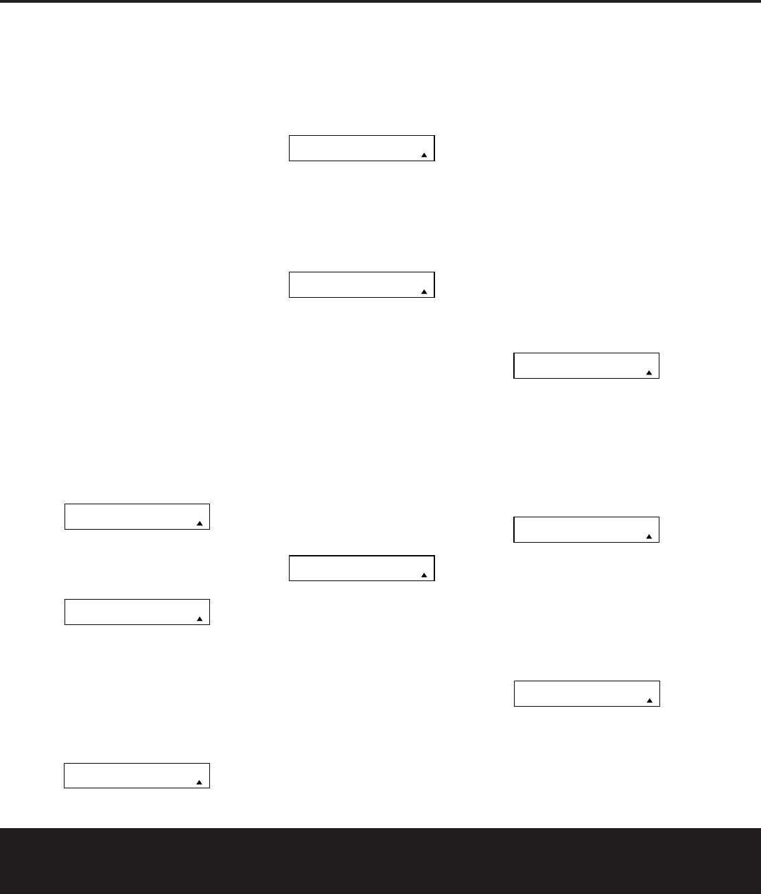
Toset the delay time for a specific input,the
DELAYADJUSTmenu (Figure 7) should be
visible on your on-screen display. If the system is not
already at that point,press the
OSD ButtonUto
bring up the MASTERMENU, press the
¤
Navigation Button nuntil the on-screen
›
cursor
is pointing at the DELAYADJUSTline. Press
the Set Button pto call up the menu.
Figure 7
Once the DELAYADJUSTmenu is on your
screen,note that the default setting to enter the dis-
tances from the speakers to the listening position is in
feet.If your measurements are in feet,proceed to the
next step;if your measurements are made in meters,
press the
¤
Navigation Button nuntil the on-
screen
›
cursor is at the UNITline on the menu.
Then,press the
‹
/
›
Navigation Button nso
that METERis highlighted.When the change
in measurement units is made,press the
⁄
/
¤
Navigation Button nto return the
›
cursor to
the CENTERposition.
With the on-screen
›
cursor pointing to CENTER,
press the
‹
/
›
Navigation Button nuntil the dis-
tance from the center speaker to the preferred listen-
ing position is entered.Next,press the
¤
Navigation
Button nto move the cursor to the SUR-
ROUNDline and use the
‹
/
›
Navigation Button
nagain to enter the distance from the video display
at the front of the room to the surround speakers.
Finally, if the system is configured for 7.1 operation by
entering LARGEorSMALLon the SURR
BACKline of the SPEAKERSETUPmenu,
press the
¤
Navigation Button nagain and use
the
‹
/
›
Navigation Button nto enter the dis-
tance from the video display at the front of the room
to the surround speakers.Remember that this last
adjustment will only be needed when you have
surround back speakers installed and Dolby Digital
chosen as the surround mode.
When the speaker-to-listening-position distance has
been entered for all active speaker positions,press the
⁄
/
¤
Navigation Button nuntil the on-screen
cursor is next to BACKTOMASTERMENU
and press the Set Button p.
The delay settings may be changed at any time
directly from the remote control by pressing the
Delay Select Button. CENTERDELAY
will appear in the Lower Display Line B, but you
may press the
⁄
/
¤
Navigation Button nto
select any of the speaker groups.
Press the Set Button pwhen the desired speaker
group appears,and then press the
⁄
/
¤
Navigation
Button nagain to enter the distance from the
speaker to the listening position.Press the Set Button
pagain to enter the data.You may then press the
⁄
/
¤
Navigation Button nto select another
speaker group to repeat the procedure as needed,or
wait five seconds for the system to return to normal
operation.
Output Level Adjustment
Output level adjustment is a key part of the configura-
tion of any surround sound product.It is particularly
important for a digital receiver such as the AVR 7200,
as correct outputs ensure that you hear soundtracks
with the proper directionality and intensity.
IMPORTANT NOTE: Listeners are often confused
about the operation of the surround channels.While
some assume that sound should always be coming
from each speaker,most of the time there will be little
or no sound in the surround channels.This is because
they are only used when a movie director or sound
mixer specifically places sound there to create ambi-
ence,a special effect or to continue action from the
front of the room to the rear.When the output levels
are properly set,it is normal for surround speakers to
operate only occasionally.Artificially increasing the
volume to the surround or surround back speakers
may destroy the illusion of an enveloping sound field
that duplicates the way
you hear sound in a movie
theater or concert hall.
Before beginning the output level adjustment process,
make certain that all speaker connections have been
properly made.The system volume should be set to
the level that you will use during a typical listening
session.While the AVR 7200 allows you to set output
levels manually, we recommend that the EzSet system
be used when the AVR is first installed to establish the
initial level settings.
Using EzSet
Harman Kardon’s exclusive EzSet remote makes it possi-
ble to quickly and accurately set the AVR7200’s output
levels without the use of a sound-pressure meter,
although manual adjustment is also available.However,
for the easiest setup,follow these steps while seated in
the listening position that will be used most often:
1. Make certain that all speaker positions have been
properly configured for their “large” or “small”set-
tings (see pages 21 – 23) and turn off the OSD
system if it is in use.
2.Adjust the volume so that it is at
15dB,as
shown in the on-screen display or Lower Display
Line B.
3.Press and hold the SPL Select Buttonon
the remote until the red LED under the Set Button
plights and the LCD screen in the remote
changes to the display shown in Figure 8.
Figure 8
4.Press the Set Button pwithin five seconds to
move to the next step.
5. Press the
⁄
Navigation Button nuntil the lower
line of the remote’s LCD display shows the number of
speakers in your system.(Don’t count the subwoofer
or speakers that are part of a multizone system.) For
example,if you have left, center,right,surround left and
right,and surround back left and right speakers for a
SET SPKR LEVELS
EZSET
43
35
* DELAY ADJUST *
CENTER:10FT
SURROUND:10FT
SURR BACK:10FT
UNIT:FEET METER
BACK TO MASTER MENU
AVR 7200 OM 1/27/03 4:46 PM Page 24
SYSTEM CONFIGURATIONSYSTEM CONFIGURATION
SYSTEM CONFIGURATION 25SYSTEM CONFIGURATION 25
full 7.1 system,press the button twice so that the bot-
tom line reads 7 CHANNELS,as shown in Figure 9.
Figure 9
6.Hold the remote in front of you at arm’s length, being
sure not to cover the EzSet Microphone Sensor
at the top of the remote,and press the Set
Button pwithin five seconds to begin the EzSet
calibration process.At this point,EzSet will take con-
trol of your AVR,starting the test tone at the front left
speaker,and automatically adjusting the output level
so that this is correct.During the adjustment the on-
screen display and the
Lower Display Line Bwill
display the speaker position on the left side of the dis-
play and the offset from reference level on the right
side of the display.As the levels are adjusted,the
speaker position and a level indication will appear in
the bottom line of the remote’s LCD display.
Figure 10
• The channel position being adjusted will flash in the
Speaker/Channel Input Indicators E.If the
test noise is heard from a channel other than the
one shown in the Indicator,there is an error in the
speaker connections.If this is the case, press the
Test Button fTWICE to stop the adjustment.
Then,turn the unit off and verify that all speakers
are connected to the proper
Speaker Outputs
¡£bcand that any connections made to
speakers powered by optional amplifiers through
the
Preamp Outputs ‹are correct.
• During the adjustment process for each channel,
you will see indications of
LOW,HIGHand a level
readout in dB.This is normal,and it confirms that
EzSet is doing its job of changing the levels to
match the desired reference.
• If a channel cannot be adjusted to the proper
reference level,you will see
FAIL displayed in
the remote’s bottom LCD line before the test tone
moves to the next channel.This is usually an indi-
cation that the volume control was set too low.
When EzSet stops circulating the tone through all
channels and returns to normal, adjust the volume
level and repeat the procedure from Step 3.
7.After the test noise has circulated once through each
channel,it will send the tone to each channel once
again,to verify the settings.
8.After two complete circulations of the tone,the levels
are set.Upon completion of the second circulation,
the
LCD Information Display cwill flash
COMPLETE three times and then go out.The
tone will stop and the AVR7200 will return to
normal operation.
If you find that the output levels chosen by EzSet are
either uncomfortably low or high,you may repeat the
procedure.Return to Step 2 and adjust the master vol-
ume either slightly higher or lower to accommodate your
particular room layout and your tastes.You may repeat
this procedure as many times as necessary to achieve a
desired result.In order to prevent possible damage to
your hearing or your equipment,we emphasize that you
should avoid setting the master volume above 0dB.
NOTE: The subwoofer output is not adjusted when the
test tone is in use.To adjust the subwoofer output you
must use an external source, following the instructions
on page 33.
Manual Output Level Adjustment
Output levels may also be adjusted manually, either to
set them to a specific level with an SPL meter, or to
make fine tuning adjustments to the levels obtained
using the EzSet remote.
Figure 11
Manual output level adjustment is most easily done
through the CHANNELADJUSTmenu
(Figure 11).If you are already at the MASTER
MENU, press the
¤
Navigation Button nuntil
the on-screen
›
cursor is next to the CHANNEL
ADJUSTline.If you are not at the MASTER
MENU, press the OSD ButtonUto bring up the
MASTERMENU(Figure 1),and then press the
¤
Navigation Button nuntil the on-screen
›
cursor is next to the CHANNELADJUSTline.
Press the Set Buttonpto bring the CHAN-
NELADJUSTmenu (Figure 11) to the screen.
When the CHANNELADJUSTmenu
appears,press the
¤
Navigation Button nuntil
the on-screen
›
cursor is next to the TEST
TONEline.Press the
‹
/
›
Navigation Button n
so that ONis highlighted and the AVR’s internal test
tone will begin to circulate from speaker to speaker in
a clockwise direction into all speakers.The test noise
will play for two seconds in each speaker before circu-
lating, and a blinking on-screen cursor will appear next
to the name of each speaker location when the sound
is at that speaker.
NOTE: Remember to verify that the speakers have
been properly connected.As the test noise circulates,
listen to make certain that the sound comes from the
speaker position shown in the Main Information
Display ˜. If the sound from a speaker location
does NOT match the position indicated in the display,
turn the AVR 7200 off using the
Main Power Switch
1and check the speaker wiring or connections to
external power amplifiers to make certain that each
speaker is connected to the correct output terminal.
After checking for speaker placement,let the test
noise circulate again,and listen to see which channels
sound louder than the others.Using the front left
speaker as a reference,press the
‹
/
›
Navigation
Button non the remote to bring all speakers to the
same volume level.When the
‹
/
›
Navigation Button
nis pushed,the test noise circulation will pause on
the channel being adjusted to give you time to make
the adjustment.When you release the button,the cir-
culation will resume after five seconds.
Continue to adjust the individual channels until the
volume level sounds the same from each speaker.
Adjustments should be made with the
‹/›Navigation
Button non the remote only,NOT the main volume
controls.If you are using a sound-pressure level (SPL)
meter for precise level adjustment,set the volume so
that the meter reads 75dB, C-Weighting Slow.
The AVR’s EzSet feature may also be used as an SPL
meter to assist in accurate setting of the output levels,
when either the internal test tone or an external source
such as a test disc is used.To use the remote as an
SPL meter,follow these steps:
1.Press and hold the
SPL Select Buttonon
the remote until the red LED under the Set Button
plights and the LCD screen in the remote
changes to the display shown in Figure 8.
2.Press the
⁄
Navigation Button nonce to
change the bottom line of the remote’s LCD display
to read
MANUAL SPLas shown in Figure 12.
Figure 12
3.Press the Set Buttonpwithin five seconds to
activate the remote’s manual mode, so that it func-
tions as an SPL meter.The right corner of the bot-
tom line of the remote’s display will show the output
level of the speakers as the test tone circulates.The
SET SPKR LEVELS
MANUAL SPL
43
* CHANNEL ADJUST *
FL:0 dBSBR:0 dB
CEN:0 dBSBL:0 dB
FR:0 dBSL:0 dB
SR:0 dBSUB:0 dB
CHANNEL RESET:OFF ON
TEST TONE:OFF ON
BACK TO MASTER MENU
EZSET CHANNELS: 5
SPEAKER:1 68dB
44
SELECT # SPEAKERS
7 CHANNELS
AVR 7200 OM 1/27/03 4:46 PM Page 25
SYSTEM CONFIGURATIONSYSTEM CONFIGURATION
26SYSTEM CONFIGURATION26SYSTEM CONFIGURATION
level will show as a direct SPL indication between
66dB and 79dB. Below 66dB the remote will
read LOW and above 79dB it will read HIGH.
4.When you are finished with all adjustments,press
the Clear Button
9
to return the remote to nor-
mal operation.
NOTE: The subwoofer level is not adjustable when the
normal test tone is in use.The subwoofer output level
may also be adjusted when the channel levels are
being trimmed to a program source rather than the
test tone,as shown on page 33.
When all channels have an equal volume level,the
adjustment is complete.To exit this menu, press the
⁄
/
¤
Navigation Button nuntil the on-screen
›
cursor is next to the BACKTOMASTER
MENUline,and then press the Set Buttonpto
return to the MASTERMENU.
The output levels may also be adjusted at any time
using the remote control and semi-OSD system.To
adjust the output levels in this fashion,press the
Test
Button f. As soon as the button is pressed,the
test tone will begin to circulate as indicated earlier.The
correct channel from which the test noise should be
heard will be shown in the lower third of the video
screen and in the
Lower Display Line B.While the
test noise is circulating, the proper channel position will
also be indicated in the
Speaker/Channel Input
IndicatorsEby a blinking letter within the correct
channel.
Toadjust the output level,press the
⁄
/
¤
Navigation Button nuntil the desired level is
shown in the display or on screen.Once the buttons
are released,the test noise will begin to circulate again
in five seconds.
When all channels have the same output level,press
the
Test Button fagain to complete the process.
NOTE: Output level adjustment is not available for the
VMAx or Surround Off modes.
Additional Input Adjustments
After one input has been adjusted for Surround mode,
digital input (if any),speaker type,and output levels,
go back to the
IN/OUTSETUPline on the
MASTERMENU(Figure 1) and enter the set-
tings for each input that you will use.In most cases,
only the digital input and surround mode will be differ-
ent from one input to the next,while the speaker type,
crossover frequency, Night mode and output level
settings will usually be the same and may be quickly
entered by entering the same data used for the
original input.
When all settings and adjustments have been made,
press the
OSD Button Uto return to normal oper-
ation of the AVR.
Once the settings outlined on the previous pages have
been made,the AVR 7200 is ready for operation.
While there are some additional settings to be made,
these are best done after you have had an opportunity
to listen to a variety of sources and different kinds of
program material.These advanced settings are
described on pages 34 to 35 of this manual.In addi-
tion,any of the settings made in the initial configura-
tion of the unit may be changed at any time.As you
add new or different sources or speakers,or if you
wish to change a setting to better reflect your listening
taste,simply follow the instructions for changing the
settings for that parameter as shown in this section.
Having completed the setup and configuration process
for your AVR 7200,you are about to experience the
finest in music and home theater listening. Enjoy!
AVR 7200 OM 1/27/03 4:46 PM Page 26
OPERATION
Basic Operation
Once you have completed the initial setup and configu-
ration of the AVR 7200,it is simple to operate and
enjoy.The following instructions will help you maximize
the enjoyment of your new receiver:
Turning the AVR 7200On or Off
• When using the AVR 7200 for the first time,you must
press the
Main Power Switch
1
on the front panel
to turn the unit on.This places the unit in a Standby
mode,as indicated by the amber color of the
Power
Indicator
3
.Once the unit is in Standby, you may
begin a listening session by pressing the
System
Power Control
2
on the front panel,or the Power
On Button
bor AVRSelectoreon the
remote.The
PowerIndicator
3
will turn green.
This will turn the unit on and return it to the input
source that was last used.The unit may also be turned
on from Standby by pressing any of the
Input
Selector Buttons
deWf
∫ç∂
on the remote or the Input Source Selector Button
%
on the front panel.
NOTE: After pressing one of the Input Selector
Buttons dfto turn the unit on, press the AVR
Selector eto set the remote control to the
AVR7200 functions.
Toturn the unit off at the end of a listening session,
simply press the
System Power Control 2on the
front panel or the
Power Off Button a
å
on the
remote.Power will be shut off to any equipment
plugged into the rear-panel
Switched AC Accessory
Outlet
aand the Power Indicator 3will turn
amber.
When the remote is used to turn the unit “off”it is
actually placing the system in a Standby mode,as indi-
cated by the amber color of the Power Indicator 3.
• To program the AVR 7200 for automatic turn-off,
press the
Sleep ButtonSon the remote.Each
press of the button will decrease the time before
shutdown in the following sequence:
•The sleep time will be displayed in the
Lower
Display Line
Band it will count down until the
time has elapsed.
•
When the programmed sleep time has elapsed,the
unit will automatically turn off.The front-panel display
will dim to one half brightness when the Sleep func-
tion is programmed.To cancel the Sleep function,
press and hold the
Sleep ButtonSuntil the
information display returns to normal brightness; the
Sleep indicator numbers will disappear and the
words SLEEPOFFwill appear in the Lower
Display Line B
.
•
W
hen you will be away from home for an extended
period of time it is always a good idea to completely
turn the unit off with the front-panel Main Power
Switch
1
.
NOTE: All preset memories are lost if the unit is left
turned off by using the Main Power Switch
1
for
more than two weeks.
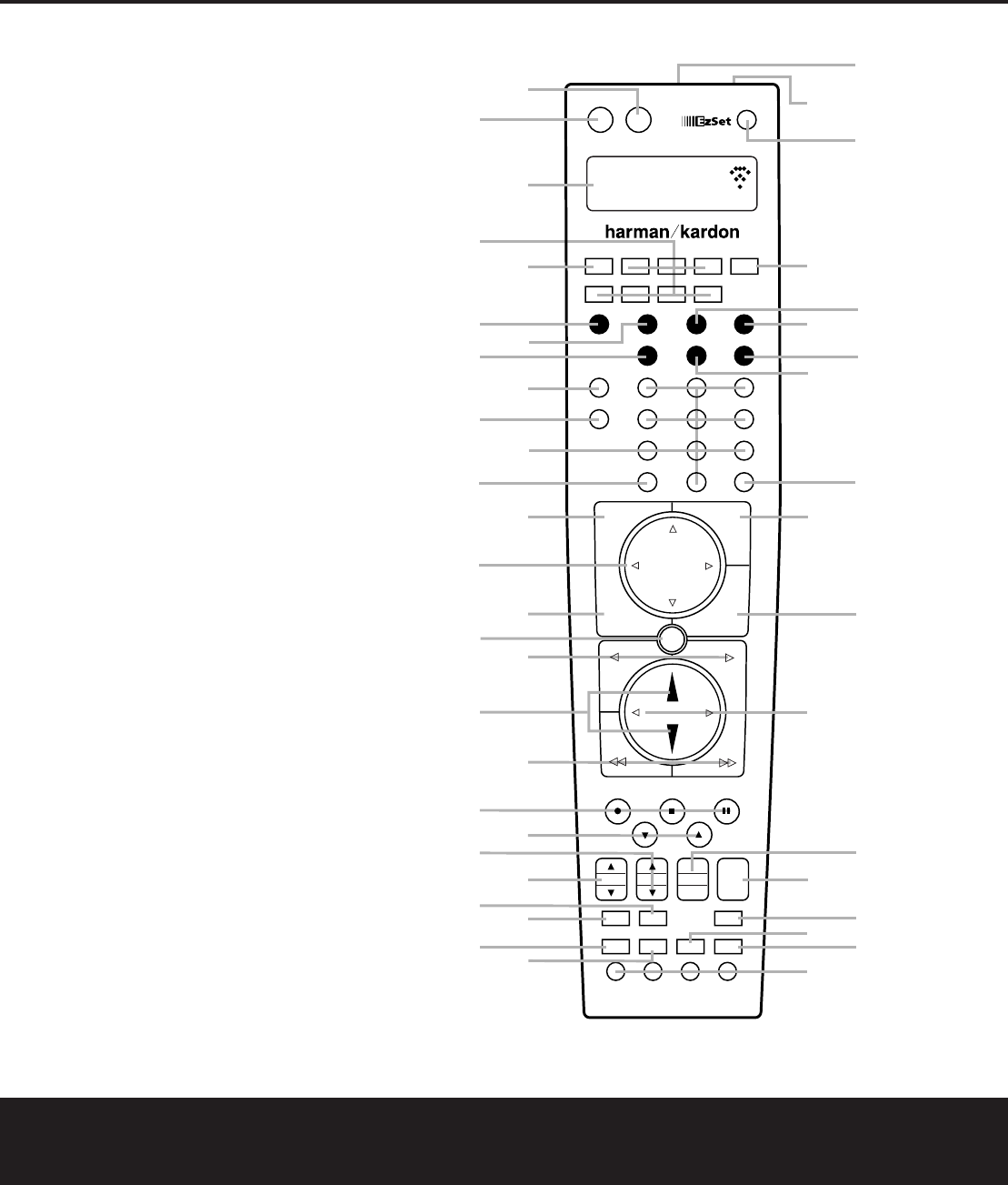
Remote Control Operation
The AVR7200’s advanced remote includes a two-line
LCD display that makes it easy to operate both the
AVR and any other product that the remote has been
programmed for.Complete information on program-
ming the remote for operation with other devices and
configuring its options are found on pages 38 – 47.
The following items provide some additional details on
using the remote with the AVR 7200:
•The name of the command code transmitted when
a button is pressed printed on the button key or just
to the top of the button on the remote itself.In addi-
tion,when a button is pressed,the function being
transmitted will also appear in the bottom line of the
remote’s LCD display.
• In order to send a command to the AVR 7200,the
AVR Selector emust be pressed.To send a
command to another device,first press the Input
Selector dfor that device.
•The remote will automatically return to the controls
for the AVR 7200 within five seconds after the but-
ton for another device is pressed.
•The factory default setting for the remote is to have
the Volume Up/Down randMutebuttons
operate the AVR 7200,regardless of which device
(such as a DVD or another video source) is in use.
•The factory setting for the remote is to have the
Transport Forward/Reverse Play Buttons
G
,
Transport Fast Play/Scan Forward/Reverse
Buttons
I
, Main Transport Controls
J
and
Track Skip Up/Down Buttons
K
operate the
DVD player,regardless of which device (including
the AVR) is in use.This simplifies operation, as in
normal use you will use the AVR controls,and this
means that you do not have to press the DVD
button to control a player.
You may change the “punch-through”setting which
allows the buttons for Volume,Transport Control or
Channel Up/Down to be assigned into another device
by following the instructions on pages 42 – 43.
•The remote has a built-in backlight that may be
activated by pressing the Light Button
P
.This
button is made from a special “glow” material so
that it is easier to find in dark rooms.This glow
feature does not use any electricity, but the glow will
fade when the remote is kept in a dark location for an
extended period of time.Restore the “glow” feature by
placing the remote in normal room light for a few hours.
•The remote’s backlight will remain lit for approxi-
mately five seconds after the Light Button
P
is
pressed,and it will stay lit for another five seconds
if any key is pressed while the backlight is on.You
may keep the backlight lit by holding the Light but-
ton,but note that extensive use of the backlight will
reduce battery life.
•The LCD display will remain on for 10 seconds
after a key is pressed and then turn off to conserve
battery life.
•When any button is held for more than 30 seconds
the LCD will turn off and the remote will stop trans-
mitting the codes to conserve battery life.
• Some of the buttons on the remote do not have a
function on certain devices.For example, the Channel
Up/Down buttons do not operate in the normal AVR
mode unless they have been assigned for this
purpose using the “punch-through” process as
explained on pages 42 – 43.This is normal and does
not indicate any problem with the remote.When it is
normal for a button not to have a function, you will see
the device name in the top left side of the remote’s
LCD display, but you will not see the transmit icon on
the upper right side of the display or any button
function name on the bottom line of the display.
Source Selection
•Toselect a source, press any of the remote Input
Selector Buttonsdf
ç∂
.
•The input source may also be changed by pressing
the front panel
Input Source Selector Button %.
Each press of the button will move the input selec-
tion through the list of available inputs.
•As the input is changed, the AVR 7200 will auto-
matically switch to the digital input (if selected),sur-
round mode,speaker configuration,output levels,
crossover frequency and night mode status that
were entered during the configuration process for
that source.
• The front-panel
Video 4 Inputs
Ó
,Optical Digital
3 Input
&
or the Coaxial Digital 3 Input
(
may
be used to connect a device such as a video game
or camcorder to your home entertainment system on
a temporary basis.
•As the input source is changed, the new input name
will appear momentarily as an on-screen display in
the lower third of the video display.The input name
will also appear in the
Main Information Display
˜and a green LED will light next to the selected
input’s name in the front-panel Input Indicators
ˆ.
32
90
min
80
min
70
min
60
min
50
min
40
min
30
min
20
min
10
min
OFF
OPERATION 27
AVR 7200 OM 1/27/03 4:46 PM Page 27
OPERATION
28 OPERATION
• When an audio source is selected, the last video input
used remains routed to the Video 1/Video 2
Outputs ¢⁄and Video Monitor Outputs d.
This permits simultaneous viewing and listening to
different sources.
•
When a composite or S-Video source is selected,the
video signal for that input will be routed to the
Video
Monitor Output
d
and will be viewable on a TV
monitor connected to the AVR 7200.
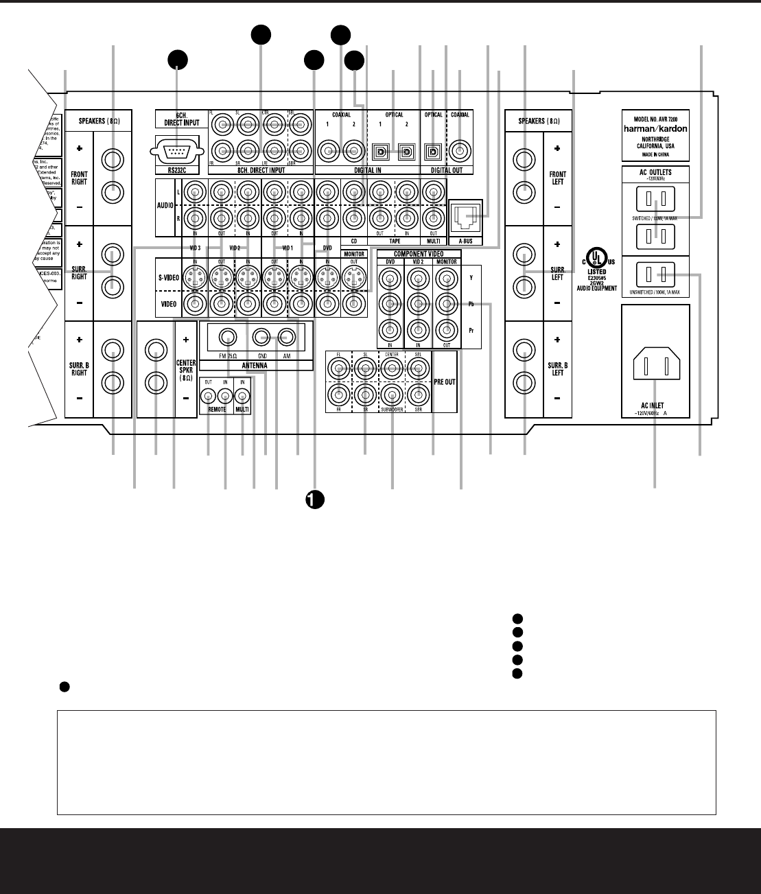
6-Channel/8-Channel Direct Input
• There are four input choices available for use with
sources such as a DVD-Audio or SACD player that are
connected to the
8-Channel Direct Inputs.
Select the appropriate input according to the way your
system and source equipment is configured:
■The 6CHDIRECTinput should be used
when the SBR and SBL inputs are NOT in use
and the input source device has its own internal
bass management system.This input passes the
input from the source directly through to the vol-
ume control without any analog to digital conver-
sion and it mutes the unused input jacks to pre-
vent unwanted noise from interfering with system
performance.
■The 6CHDVDAUDIOinput should be
used when the SBR and SBL inputs are NOT in
use and the input source device does NOT have
its own internal bass management system.When
this input is in use the analog source is converted
to digital so that you may use the same Triple
Crossover bass management options for the
direct input as you do with all other outputs.This
input also mutes the unused input jacks to pre-
vent unwanted noise from interfering with system
performance.
■The 8CHDIRECTINPUTshould
be used when an input is connected to all eight
8-Channel Direct Inputsand when the
input source device has its own internal bass
management system.This input passes the input
from the source directly through to the volume
control without any analog to digital conversion
and it mutes the unused input jacks to prevent
unwanted noise from interfering with system
performance.
■The 8CHDVDAUDIOinput should
be used when an input is connected to all eight
8-Channel Direct Inputsand the input
source device does NOT have its own internal
bass management system.When this input is in
use the analog source is converted to digital so
that you may use the same Triple Crossover bass
management options for the direct input as you
do with all other outputs.This input also mutes
the unused input jacks to prevent unwanted noise
from interfering with system performance.
Volume Control
•Adjust the volume to a comfortable level using the
front panel Volume Control ıor remote Volume
Up/Down Buttons r.
•Totemporarily silence all speaker outputs, press the
Mute ButtonK.This will interrupt the output
to all speakers and the headphone jack,but it will
not affect any recording or dubbing that may be in
progress.When the system is muted,the word
MUTEwill flash in the Main Information Display
˜. Press the Mute ButtonKagain to
return to normal operation.
•You may adjust the bass and treble tone controls at
any point during a listening session by simply turning
the
Bass Control Ôor Treble Control Òuntil
the desired setting is achieved.You may also totally
remove the tone controls (including the
Balance
Control ) from the circuit so that the output is
“flat”at any time by pressing the Tone Mode
Button 5and then pressing the
‹/›Buttons
)#so that TONEOFFappears in the on-
screen display and the Lower Display Line B.
•For private listening,plug the 1/4" stereo phone
plug from a pair of stereo headphones into the
front-panel
Headphone Jack
4
.When the
headphone’s plug is connected,the word
HEADPHONEwill scroll once across the
Lower Display Line Band all speakers will be
silenced.When the headphone plug is removed,the
audio feed to the speakers will be restored.
Surround Mode Selection
Selection of a surround mode is based on personal
taste,as well as the type of program source material
being used.For example, motion pictures or TV pro-
grams bearing the logo of one of the major surround-
encoding processes,such as Dolby Surround, DTS
Stereo or UltraStereo
®may be played in either the
Dolby Digital,Dolby Pro Logic II Cinema, DTS Neo:6
Cinema,or Logic 7 Cinema surround modes depending
on the source material.
NOTE: Once a program has been encoded with matrix
surround information, it retains the surround information
as long as the program is broadcast in stereo.Thus,
movies with surround sound may be decoded via any
of the analog surround modes such as Pro Logic II
Cinema,Logic 7 Cinema or DTS Neo:6 Cinema, when
they are broadcast via conventional TV stations, cable,
pay-TV and satellite transmission.In addition, a growing
number of made-for-television programs,sports broad-
casts,radio dramas and music CDs are also recorded in
surround sound.You may view a list of these programs
at the Dolby Laboratories Web site at www.dolby.com.
Even when a program is not listed as carrying intentional
surround information, you may find that the Pro Logic II,
Logic 7 Enhanced or DTS Neo:6,VMAx and the Hall or
Theater modes often deliver enveloping surround pre-
sentations through the use of the natural information
present in all stereo recordings.
Surround modes may be changed at any time by
using either the front panel or remote control.To
select a new surround mode from the front panel,first
press the
Surround Mode Group Selector Button
7until the desired major surround mode group such
as Dolby, DTS or Logic 7 is selected.Next, press the
Surround Mode Selector Button 8to choose the
specific individual surround mode.
Toselect a surround mode using the remote,press
the button for the major surround mode group that
you wish to choose from:
Dolby e,DTS Surround
d, DTS Neo:6 , Logic 7 h,Stereo
or DSP Surround g. The first press of the button
will show the current mode from that group if it is
already in use,or the first available mode if you are
currently using another mode.To cycle through the
modes in that group,press the button again until the
desired mode appears in the
Lower Display Line B
and the on-screen display.
As the surround modes change,a green LED will light
next to the current mode in the
Surround Mode
Indicators
˘list on the front panel.
The Dolby Digital,Dolby Digital EX and DTS 5.1,
DTS-ES Matrix and DTS-ES Discrete modes may only
be selected when a digital input is in use.In addition,
when a digital source is present,the AVR 7200 will
automatically select and switch to the correct mode,
regardless of the mode that has been previously
selected. For more information on selecting digital
sources, see the Digital Audio Playback section below.
NOTE: When a single speaker is used for the rear
surround channels as a 6.1 configuration,the Logic 7/
7.1 and 7-Channel Stereo modes should not be
used.However,Dolby Digital EX and DTS will function
normally.
When the 6-channel/8-channel direct inputs are in
use there is no surround processing, as these inputs
take the analog output signals from an optional,exter-
nal DVD-Audio or SACD player,or another source
device and carry them straight through to the volume
control without any further digital processing.
38
39
32
32
34
34
34
AVR 7200 OM 1/27/03 4:46 PM Page 28
OPERATION
OPERATION 29
Surround Mode Chart
MODEFEATURES
Dolby DigitalAvailable only with digital input sources encoded with Dolby Digital data.It provides up to five separate main audio channels and
a special dedicated Low-Frequency Effects channel.When the Dolby Digital data stream contains a two-channel (2.0) signal,the
Dolby Pro Logic II-Movie processing circuits will automatically be activated to produce a multichannel surround presentation.
Dolby Digital EXAvailable when the receiver is configured for 6.1/7.1 channel operation, Dolby Digital EX is the latest version of Dolby Digital.When used with
movies or other programs that have special encoding, Dolby Digital EX reproduces specially encoded soundtracks so that a full 6.1/7.1 soundfield is
available.When the receiver is set for 6.1/7.1 operation and a Dolby Digital signal is present,the EX mode is automatically selected.Even if specific
EX encoding is not available to provide the additional channel,the special algorithms will derive a 6.1/7.1 output.
DTS 5.1When the speaker configuration is set for 5.1-channel operation,the DTS 5.1 mode is available when DVD, audio-only music or laser discs encoded
with DTS data are played.DTS 5.1 provides up to five separate main audio channels and a special dedicated low-frequency channel.
DTS-ES 6.1 MatrixWhen the speaker configuration is set for 6.1/7.1 operation,playback of a DTS-encoded program source will automatically trigger the selection
DTS-ES 6.1 Discreteof one of the two DTS-ES modes.Newer discs with special DTS-ES discrete encoding will be decoded to provide six discrete, full-bandwidth
channels plus a separate low-frequency channel.All other DTS discs will be decoded using the DTS-ES Matrix mode,which creates a 6.1-channel
sound field from the original 5.1-channel soundtrack.
Dolby Pro Logic IIDolby Pro Logic II is the latest version of Dolby Laboratory’s benchmark surround technology that decodes full-range, discrete left,center right,
Movieright surround and left surround channels from either matrix surround encoded programs and conventional stereo sources when an analog input
Musicis in use.The Dolby Pro Logic II Movie mode is optimized for movie soundtracks,while the Pro Logic II Music mode should be used with
Emulationmusical selections.The Pro Logic II Emulation mode re-creates original Pro Logic processing for those who prefer that presentation.
Logic 7 CinemaExclusive to Harman Kardon for A/Vreceivers, Logic 7 is an advanced mode that extracts the maximum surround information from either
Logic 7 Musicsurround-encoded programs or conventional stereo material.Depending on the number of speakers in use and the selection made in the
Logic 7 Enhance
SURROUNDSELECTmenu,the “5.1” versions of Logic 7 modes are available when the 5.1 option is chosen,while the “7.1”versions of
Logic 7 produce a full sound field presentation,including back surround speakers when the “6.1/7.1” option is chosen.The Logic 7 C (or Cinema)
mode should be used with any source that contains Dolby Surround or similar matrix encoding. Logic 7 C delivers increased center-channel
intelligibility, and more accurate placement of sounds with fades and pans that are much smoother and more realistic than with other decoding
techniques.Logic 7 M (Music) enhances the listening experience by presenting a wider front soundstage and greater rear ambience.When a PCM
digital audio signal is detected,the Logic 7 Music mode will automatically be selected.Both Logic 7 modes also direct low-frequency information to
the subwoofer (if installed and configured) to deliver maximum bass impact.The Logic 7 E (or Enhance) mode,available only when the 5.1 option is
chosen,is an extension of the Logic 7 modes that is primarily used with musical programs.Logic 7 E adds additional bass enhancement that
circulates low frequencies in the 40Hz to 120Hz range to the front and surround speakers to deliver a less localized soundstage that appears
broader and wider than when the subwoofer is the sole source of bass energy.
DTS Neo:6 CinemaThese two modes are available when any analog source is playing to create a six-channel surround presentation from conventional Matrix-encoded
DTS Neo:6 Musicand traditional Stereo sources.Select the Cinema version of Neo:6 when a program with any type of analog Matrix surround encoding is present.
Select the Music version of Neo:6 for optimal processing when a nonencoded,two-channel stereo program is being played.
Dolby 3 StereoUses the information contained in a surround-encoded or two-channel stereo program to create center-channel information. In addition,the
information that is normally sent to the rear-channel surround speakers is carefully mixed in with the front-left and front-right channels for increased
realism.Use this mode when you have a center channel speaker but no surround speakers.
TheaterThe Theater mode creates a sound field that resembles the acoustic feeling of a standard live performance theater.
Hall 1,Hall 2The two Hall modes create sound fields that resemble a small (Hall 1) or medium-sized (Hall 2) concert hall.
VMAx NearWhen only the two front-channel loudspeakers are used,Harman’s patented VMAx mode delivers a three-dimensional sound space with the illusion
VMAx Farof “phantom speakers” at the center and surround positions.The VMAx N, or “Near Field,” mode should be selected when your listening position is
less than five feet from the speakers.The VMAx F,or “Far Field,” mode should be selected when your listening position is greaterthan five feet from
the speakers.The VMAx modes are also available using the
Headphones Output 4.When headphones are being used,the Far Field mode will
appear to push the sound field away from your ears,reducing the “inside the head” sensation often experienced when using headphones.
5-Channel StereoThis mode takes advantage of multiple speakers to place a stereo signal at both the front and back of a room.Depending on whether the AVR
7-Channel Stereohas been configured for either 5.1 or 6.1/7.1 operation,one of these modes, but not both,is available at any time.Ideal for playing music in
situations such as a party, it places the same signal this mode at the front-left and surround-left,and front-right and surround-right speakers.
The center channel is fed a summed mono mix of the in-phase material of the left and right channels.
SurroundThis mode turns off all surround processing and presents the pure left- and right-channel presentation of two-channel stereo programs.
Off (Stereo)
OPERATION 29
AVR 7200 OM 1/27/03 4:46 PM Page 29
OPERATION
30OPERATION
Tolisten to a program in traditional two-channel stereo,
using only the front left and front right speakers (plus a
subwoofer,if installed and configured), press the
Stereo Buttonon the remote once or twice until
SURROFFappears in the Main Information
Display ˜.From the front panel, press the Surround
Mode Group Selector 7untilSTEREO
MODESappears in the on-screen display and
Lower Display Line B. Next,press the Surround
Mode Select Button 8until the display message
reads SURROUNDOFF.
Digital Audio Playback
Digital audio is a major advancement over older analog
surround processing systems such as Dolby Pro Logic.
It delivers five discrete channels:left front, center,right
front,left surround and right surround. Each channel
reproduces full frequency range (20Hz to 20kHz) and
offers dramatically improved dynamic range and signifi-
cant improvements to signal-to-noise ratios.In addition,
digital systems have the capability to deliver an additional
channel that is specifically devoted to low-frequency
information.This is the “.1” channel referred to when you
see these systems described as “5.1,”“6.1” or “7.1”.
The bass channel is separate from the other channels,
but since it is intentionally bandwidth-limited,sound
designers have given it that unique designation.
Dolby Digital
Dolby Digital is a standard on DVDs,and is available on
specially encoded LD discs and satellite broadcasts and
high-definition television (HDTV) broadcasts.
An optional,external RF demodulator is required to
use the AVR 7200 to listen to the Dolby Digital sound-
tracks available on laser discs.Connect the RF output
of the LD player to the demodulator and then connect
the digital output of the demodulator to the
Optical or
Coaxial Inputs&(jof the AVR 7200.No
demodulator is required for use with DVD players or
DTS-encoded laser discs.
DTS
DTS is another digital audio system that is capable of
delivering 5.1 or 6.1 discrete or matrix sound field
reproduction.Although both DTS and Dolby Digital are
digital,they use different methods of encoding the sig-
nals,and thus they require different decoding circuits
to convert the digital signals back to analog.
DTS-encoded soundtracks are available on select DVD
and LD discs,as well as on special audio-only DTS
discs.You may use any LD or CD player equipped
with a digital output to play DTS-encoded discs with
the AVR 7200.All that is required is to connect the
player’s output to either an
Optical orCoaxial Input
on the rear panel jor front panel &(.
In order to listen to DVDs encoded with DTS sound-
tracks,the DVD player must be compatible with the
DTS signal as indicated by a DTS logo on the player’s
front panel.Early DVD players may not be able to play
DTS-encoded DVDs.This does not indicate a problem
with the AVR 7200,as some players cannot pass the
DTS signal through to the digital outputs.If you are in
doubt as to the capability of your DVD player to handle
DTS discs,consult the player’s owner’s manual.
NOTE: Some DVD players have a default setting that
does not pass through the DTS signal.Before playing
DVDs with a DTS soundtrack,make certain that the
settings in your DVD player have been properly adjusted
so that DTS audio is passed through.Consult the
Owner’s Manual for your DVD player for more infor-
mation on making these settings.
Selecting a Digital Source
Toutilize either digital mode,you must have properly
connected a digital source to the AVR7200. Connect
the digital outputs from DVD players,HDTV receivers,
satellite systems or CD players to the
Optical or
Coaxial Inputs&(j. In order to provide a
backup signal and a source for analog stereo recording,
the analog outputs provided on digital source equipment
should also be connected to their appropriate inputs on
the AVR 7200 rear panel (e.g.,connect the analog
stereo audio output from a DVD to the
DVD Inputs
on the rear panel when you connect the source’s digi-
tal outputs).
If you have not already configured an input for a digital
source using the on-screen menus as shown on
pages 19 – 20,first select the input using the remote
or front panel controls as outlined in this manual.Next,
select the digital source by pressing the
Digital
Select Button oPand then using the
⁄
/
¤
Navigation Button non the remote or the
‹
/
›
Selector Buttons )#on the front panel to
choose any of the OPTICALor COAXIAL
inputs,as they appear in the Upper Display Line A
or on-screen display.When the digital source is play-
ing, the AVR 7200 will automatically detect which type
of digital data stream is being decoded and display
that information in the
Upper Display Line A.
Digital Bitstream Indicators
When a digital source is playing, the AVR 7200 senses
the type of bitstream data that is present.Using this
information, the correct surround mode will automati-
cally be selected.For example, DTS bitstreams will
cause the unit to switch to DTS decoding, and Dolby
Digital bitstreams will enable Dolby Digital decoding.
When the unit senses PCM data from CDs and LDs,
it will allow the appropriate surround sources to be
selected manually. Since the range of available sur-
round modes is dependent on the type of digital data
that is present,the AVR 7200 uses display indicators
to let you know what type of signal is present.This will
help you to understand the choice of modes.
Tohelp you see which type of digital source is playing,
the
Surround Mode Indicators
˘in combination
with the Information Display
˜also serve as
bitstream indications to show which type of bitstream
is present,as well as the surround mode in use,if
applicable.
Dolby Digital:When the green LED next to the Dolby
Digital or Dolby Digital EX modes is lit,a Dolby Digital
bitstream is being received.Depending on the settings
on the source player and specific surround information
and number of channels on the disc,a number of
surround modes are possible.For discs with full 5.1
audio,only the Dolby Digital and VMAx modes are
available.
DTS: When the green LED next to the DTS logo
lights,a DTS bitstream is being received.When the
unit senses this type of data,only the applicable DTS
mode may be used.
PCM: When the green LED next to the word DIGITAL
lights,a standard Pulse Code Modulation,or PCM,sig-
nal is being received.This is the type of digital audio
used by conventional compact disc and laser disc
recordings.When a PCM bitstream is present,all
modes except Dolby Digital and DTS are available.
HDCD: When the letters HDCDappear on the
Lower Display Line Bin conjunction with the PCM
indicator,the CD that is playing is encoded through the
special High Definition Compatible Digital
®
process.
HDCD
®
discs use 20-bit encoding and other propri-
etary processing to provide the ultimate in CD listen-
ing. HDCD processing is only available in the Stereo
(Surround Off) mode.
MP3: When MP3appears on the Lower Display
Line Ba compatible MPEG 1/Layer 3 digital signal
is being received.This is the popular audio format
used by many computer programs for recording com-
pressed audio files.When an MP3 bitstream is pres-
ent,the sound will automatically be played in the
Stereo (Surround Off) mode.The surround modes are
not available during MP3 playback.There are many
different forms of MP3 encoding available and the
format is used at a number of different bit rates.The
AVR 7200 may not be compatible with all forms of
MP3,particularly when the data file is encoded at
128kb/s or above.
12
32
32
32
38
AVR 7200 OM 1/27/03 4:46 PM Page 30
OPERATION
Speaker/Channel Indicators
In addition to the bitstream indicators,the AVR 7200
features a set of unique channel-input indicators
(shown below) that tell you how many channels of dig-
ital information are being received and/or whether the
digital signal is interrupted.
These indicators are the L/C/R/LFE/SL/SR/SBL/SBR
letters that are inside the center boxes of the
Speaker/
Channel Input Indicators Ein the front-panel
Main Information Display ˜.When a standard
analog signal is in use,only the “L” and “R”indicators
will light,as
analog signals have only left and right
channels.
Digital signals,however,may have two,five,six or
seven channels,depending on the program material,
the method of transmission and the way in which it
was encoded.When a digital signal is playing, the let-
ters in these indicators will light in response to the
specific signal being received.It is important to note
that although Dolby Digital,for example,is referred to
as a “5.1” system,not all Dolby Digital DVDs or pro-
grams are encoded for 5.1.Thus,it is sometimes nor-
mal for a DVD with a Dolby Digital soundtrack to trig-
ger only the “L” and “R”indicators.
NOTE: Many DVD discs are recorded with both “5.1”
and “2.0” versions of the same sound-track.When
playing a DVD, always be certain to check the type of
material on the disc.Most discs show this information
in the form of a listing or icon on the back of the disc
jacket.When a disc does offer multiple soundtrack
choices,you may have to make some adjustments to
your DVD player (usually with the “Audio Select” button
or in a menu screen on the disc) to send a full 5.1
feed to the AVR 7200.It is also possible for the type
of signal feed to change during the course of a DVD
playback.In some cases,the previews of special
material will only be recorded in 2.0 audio,while the
main feature is available in 5.1 audio.The AVR 7200
will automatically sense changes to the bitstream and
channel count and reflect them in these indicators.
The letters used by the
Speaker/Channel Input
IndicatorsEalso flash to indicate when a bitstream
has been interrupted.This will happen when a digital
input source is selected before the playback starts,or
when a digital source such as a DVD is paused.The
flashing indicators remind you that the playback has
stopped due to the absence of a digital signal and not
through any fault of the AVR7200.This is normal,and
the digital playback will resume once the playback is
started again.
Night Mode
A special feature of Dolby Digital is the Night mode,
which enables specially encoded Dolby Digital input
sources to be played back with full digital intelligibility
while reducing the minimum peak level by 1/4 to 1/3.
This prevents abruptly loud transitions from disturbing
others,without reducing the impact of the digital
source.The Night mode is available only when Dolby
Digital signals with special data are being played.
The Night mode may be engaged when a Dolby
Digital DVD is playing by pressing the
Night Mode
Button Ton the remote. Next,press the
⁄
/
¤
Navigation Button nto select either the middle
range or full compression versions of the Night mode.
Toturn the Night mode off, press the
⁄
/
¤
Navigation Button nuntil the message in the
lower third of the video display and in the Lower
Display Line Breads D-RANGEOFF.
The Night mode may also be selected to always be on
at either level of compression using the options in the
DOLBYmenu.See page 21 for information on
using the menus to set this option.
IMPORTANT NOTES ON DIGITAL PLAYBACK:
• When the digital playback source is stopped, or in a
pause,fast forward or chapter search mode,the
digital audio data will momentarily stop,and the
channel position letters inside the
Speaker/Channel Input Indicators Ewill flash.
This is normal and does not indicate a problem with
either the AVR 7200 or the source machine.The
AVR 7200 will return to digital playback as soon as
the data is available and when the machine is in a
standard play mode.
• Although the AVR 7200 will decode virtually all current
DVD movies,CDs and HDTV sources, it is possible
that some future digital sources may not be compati-
ble with the AVR 7200.
•Not all digitally encoded programs contain full 5.1
or 6.1 channel audio.Consult the program guide
that accompanies the DVD or laser disc to deter-
mine which type of audio has been recorded on the
disc.The AVR 7200 will automatically sense the
type of digital surround encoding used and adjust to
accommodate it.
• When a digital source is playing,you may not be
able to select some of the analog surround modes
such as Dolby Pro Logic II,Dolby 3,Stereo,Hall,
Theater or Logic 7.
• When a Dolby Digital or DTS source is playing,
it is not possible to make an analog recording using
the
Tape Outputskand Video 1 or Video 2
Outputs ¢⁄. However, the digital signals will be
passed through to the Digital Audio Outputs
fh(.
PCM Audio Playback
PCM (Pulse Code Modulation) is the noncompressed
digital audio system used for compact discs and laser
discs.It is also the format used as an output by audio
transcoders such as the Harman Kardon DAL 150.
The digital circuits in the AVR 7200 are capable of
high-quality digital-to-analog decoding, and they may
be connected directly to the digital audio output of your
CD or LD player.
Connections may be made to either the rear-panel
Optical orCoaxialInputsjor the front-panel
Digital Inputs &(.
Tolisten to a PCM digital source, first select the input for
the desired source (e.g., CD).Next press the
Digital
Select Button Poand then use the
⁄
/
¤
Navigation Button non the remote,or the
‹
/
›
Selector Buttons)#on the front panel, until the
desired choice appears in the Main Information
Display ˜.
During PCM playback,you may select any Surround
mode except Dolby Digital or DTS.When an HDCD-
encoded disc is being played and the DVD or CD
player is connected to the AVR 7200 via a digital con-
nection,select Surround Off as the Surround mode to
enjoy the benefits of the HDCD process.
MP3 Audio Playback
The AVR 7200 is one of the few receivers equipped
for onboard decoding for the MP3 audio format used
by computers and portable audio devices.By offering
MP3 decoding, the AVR 7200 is able to deliver pre-
cise conversion of the digital signals to an analog out-
put,along with the benefits of listening to the MP3
audio through the AVR7200’s high-current amplifier
and the speakers from your surround system,rather
than the smaller speakers and low-powered amplifiers
typically used with computers.
Totake advantage of the AVR7200’s MP3 capabili-
ties,simply connect the PCM output of a computer’s
sound card or the PCM output of a portable digital
audio device to either the rear panel
Digital Inputs
jor the front panel Digital Inputs &(.
When the digital signal is available,the Lower Display
Line Bwill indicate that an MP3 bitstream is pres-
ent,and the audio will begin playing.
32
32
OPERATION
OPERATION 31OPERATION 31
AVR 7200 OM 1/27/03 4:46 PM Page 31
OPERATION
32 OPERATION
NOTES:
• The AVR 7200 is only capable of playing signals in
the MP3 (MPEG 1/Layer 3) format. It is not com-
patible with other computer audio codecs.
• The digital audio input signal may be either optical
or coaxial,but the signal must be in the S/P-DIF
format. Direct connection of USB or serial data out-
puts is not possible,even though the signals are in
the MP3 format. If you have any questions about
the data output format from your computer or a
sound card,check with the device’s owner’s manual
or contact the manufacturer’s technical support
area.
• If your computer or sound card’s digital output is not
capable of direct connection to the AVR 7200,you
may use an optional,external transcoder, available
from Harman Kardon, to convert the USB output of
a computer to a format compatible with the AVR.
Contact your Harman Kardon dealer for additional
details.
• Due to the wide variation in MP3 formats and
encoding speeds,it is possible that the AVR 7200
may not be compatible with all MP3 input signals.
Some may produce unacceptable results and some
may not be decoded.This is not a fault of either the
computer or the AVR 7200,but rather a by-product
of the unpredictable nature of MP3 playback.
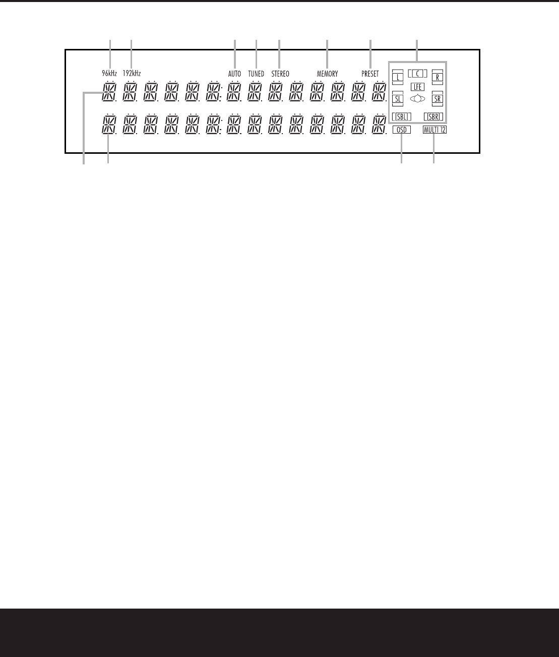
Tuner Operation
The AVR 7200’s tuner is capable of tuning AM,FM
and FM Stereo broadcast stations.Stations may be
tuned manually, or they may be stored as favorite sta-
tion presets and recalled from a 30-position memory.
Station Selection
1.Press the AM/FM Tuner SelectButton
W
ç
on the remote to select the tuner as an
input.The tuner may be selected from the front
panel by pressing
either the Input Source Selector
%until the tuner is active or the Tuner Band
Selector !at any time.
2. Press the AM/FM Tuner SelectButtonW
ç
or Tuner Band Selector !again to switch
between AM and FM so that the desired frequency
band is selected.
3. Press the
Tuner Mode Selector
^
or Tuning
Mode Buttonlto select manual or automatic tun-
ing.
When the
AUTO IndicatorJis illuminated in the
Main Information Display ˜the tuner will only
stop at those stations that have a strong-enough sig-
nal to be received with acceptable quality.
When the AUTO IndicatorJis not lit, the tuner is in
a manual mode and will stop at each frequency
increment in the selected band.
4.To select stations, press the Tuning Selector
Button
9
w
é
.When the AUTO Indicator
Jis lit,press the button to cause the tuner to
search for the next highest- or lowest-frequency
station that has an acceptable signal.Hold the
Tuning Selector Button
9
w
é
to scan
through the stations with acceptable signals.Press
the Tuner Mode Button
^
lto switch to the
manual tuning mode,in which each press of the
Tuning Selector Button
9
w
é
advances
one frequency increment,or pressing and holding
scans through all frequency increments.
When tuning FM stations in the Auto mode, the
tuner will only select stereo stations.To tune to the
next station,press the button again.If the
STEREO
IndicatorHis not lit, tap the Tuning Selector
Button
9
w
é
to advance one frequency
increment at a time,or press and hold it to locate a
specific station.When the TUNED IndicatorI
lights,the station is properly tuned and should be
heard with clarity.
5.Stations may also be tuned directly by pressing the
Direct Button i, and then pressing the
Numeric Keys
k
that correspond to the sta-
tion’s frequency.The desired station will automati-
cally be tuned.If you press an incorrect button while
entering a direct frequency, press the Clear Button
jto start over.
NOTE: When the FM reception of a station is weak,
audio quality will be increased by switching to Mono
mode by pressing the Tuner Mode Button
^
l
until the STEREO IndicatorHgoes out.
Preset Tuning
Using the remote,up to 30 stations may be stored
in the AVR 7200’s memory for easy recall using the
front-panel controls or the remote.
Toenter a station into the memory,first tune the sta-
tion using the steps outlined above.Then:
1.Press the
MemoryButtonon the remote.
The MEMORY Indicator Gwill light and flash in
the Main Information Display ˜.
2.Within five seconds,press the Numeric Keys k
corresponding to the location where you wish to
store this station’s frequency.Once entered,the
preset number will appear in the Main Information
DIsplay ˜.
3. Repeat the process after tuning any additional sta-
tions to be preset.
Recalling Preset Stations
• To manually select a station previously entered in
the preset memory,press the Numeric Keys k
that correspond to the desired station’s memory
location.
• To manually tune through the list of stored preset
Libble takes abuse of its services very seriously. We're committed to dealing with such abuse according to the laws in your country of residence. When you submit a report, we'll investigate it and take the appropriate action. We'll get back to you only if we require additional details or have more information to share.
Product:
Forumrules
To achieve meaningful questions, we apply the following rules:
First, read the manual;
Check if your question has been asked previously;
Try to ask your question as clearly as possible;
Did you already try to solve the problem? Please mention this;
Is your problem solved by a visitor then let him/her know in this forum;
To give a response to a question or answer, do not use this form but click on the button 'reply to this question';
Your question will be posted here and emailed to our subscribers. Therefore, avoid filling in personal details.
Register
Register getting emails for Harman Kardon AVR7200 at:
new questions and answers
new manuals
You will receive an email to register for one or both of the options.
Get your user manual by e-mail
Enter your email address to receive the manual of Harman Kardon AVR7200 in the language / languages: English as an attachment in your email.
The manual is 0,85 mb in size.
You will receive the manual in your email within minutes. If you have not received an email, then probably have entered the wrong email address or your mailbox is too full. In addition, it may be that your ISP may have a maximum size for emails to receive.
The manual is sent by email. Check your email
If you have not received an email with the manual within fifteen minutes, it may be that you have a entered a wrong email address or that your ISP has set a maximum size to receive email that is smaller than the size of the manual.
The email address you have provided is not correct.
Please check the email address and correct it.
Your question is posted on this page
Would you like to receive an email when new answers and questions are posted? Please enter your email address.