The color transition, seen as sharp separation of the bars. •
The performance of the color circuits in your TV (with video signals); bar edges should •
show no vertical crawling dots.
Use the gray scale and the black/white fields in the test pattern to adjust the brightness
and contrast.
Brightness Adjustment
Turn down the color control on your TV until the color bars appear in black and white.1.
Adjust the Contrast to the lowest level where you still can see all gray-scale bars 2.
separately and clearly.
Adjust the Brightness so that the bars in the gray scale are all visible. The bar farthest 3.
to the left has to be as black as possible rather than gray, but the next gradation must
clearly be distinct from it. The bars in the gray scale should gradually and evenly
change from black to white.
0295CSK - HK (x65Series) AVR3650_365_2650_265 CORE OM, WORK18 danny.indd 3501/07/11 11:34:06
AVR
36
Advanced Functions, Manual Speaker Setup
Contrast Adjustment
Adjust the contrast on your TV until you see a bright white bar in the lower right corner 1.
of the screen and a deep, dark, black bar to the left.
If the brightness of the white bar no longer increases when the Contrast is turned 2.
up or the borders of white letters bloom (overlight) into the black areas (drastically
decreasing the sharpness of the letters), the contrast has been turned up too much.
Reduce the Contrast until these effects disappear and the video still looks realistic.
If you are watching TV with ambient daylight, adjust the contrast so that a normal 3.
video picture looks the same as the surroundings in your room; that way the eye is
relaxed when watching the TV picture. Reduce the setting when the surrounding light
is dimmed to improve the sharpness of the picture.
The gray scale in the middle line should retain the same distinction between each 4.
bar as before the contrast adjustment. If not, repeat both Step 3 of the Brightness
Adjustment and the Contrast Adjustment.
Color Adjustment
When the brightness and contrast are set optimally, adjust the Color control. Set the 1.
level so that the colors look strong but still natural, not overdone. If the color level is
too high, depending on the TV, some of the bars will seem wider or the color intensity
will not increase when the control is turned up. Test the color intensity with a video of
pictures of faces, flowers, fruit and vegetables.
Refer to a large white bar in your test pattern to tweak the warmth of the picture using 2.
the Tint control on your TV.
Sharpness Adjustment
Contrary to intuition, the picture will appear sharper and clearer with the sharpness
backed off from the maximum setting. Reduce the Sharpness setting on your television,
and the setting on the AVR, if necessary, to minimize the appearance of any white lines
between the bars in the gray-scale portion of the test screen.
Manual Speaker Setup
Your AVR is flexible and may be configured to work with most speakers and to compensate
for the acoustic characteristics of your room.
The EzSet/EQ process automatically detects the capabilities of each connected speaker
and optimizes the AVR’s performance with your speakers. If you are unable to run EzSet/
EQ calibration, or if you wish to set up your AVR for your speakers manually, use the
Manual Speaker Setup on-screen menus.
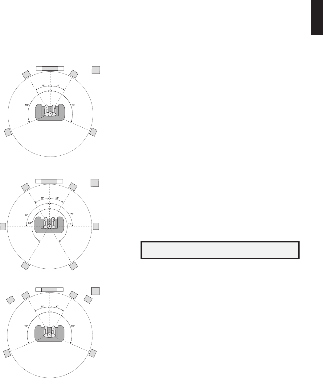
Before beginning, place your loudspeakers as explained in the
Place Your Speakers
section, on page 13, and connect them to the AVR. Consult the owner’s guide for the
speakers or the manufacturer’s Web site for their frequency-range specification. Although
you may set the AVR’s individual channel levels “by ear,” an SPL (sound-pressure level)
meter purchased at a local electronics store will provide greater accuracy.
Record your configuration settings in Tables A3 through A12 in the Appendix for easy
re-entry after a system reset or after the AVR’s Master Power switch has been turned off
or the unit has been unplugged for more than four weeks.
NOTE:When using the AVR’s Manual Speaker Setup menus, select a video output
resolution of 720p or higher to view graphics that simplify configuration.
Step One – Determine Your Speakers’ Crossover Frequencies
Without using the EzSet/EQ process, the AVR can’t detect how many speakers you’ve
connected to it; nor can it determine their capabilities. Consult the technical specifications
for all of your speakers and locate the frequency response, usually given as a range, e.g.,
100Hz – 20kHz (±3dB). Write down the lowest frequency that each of your speakers
is capable of playing (100Hz in the above example) as the crossover in Table A3 in the
Appendix. NOTE: This is not the same as the crossover frequency listed in the speaker’s
specifications.
For the subwoofer, write down the transducer size. The AVR’s bass management
determines which speakers will be used to play back the low-frequency (bass) portion
of the source program. Sending the lowest notes to small satellite speakers will result in
bad sound and may even damage the speakers. The highest notes may not be heard at
all through the subwoofer.
With proper bass management, the AVR divides the source signal at a crossover point.
All information above that crossover point is played through your system’s speakers,
and all information below the crossover point is played through the subwoofer. This way,
each loudspeaker in your system will perform at its best, delivering a more powerful and
enjoyable sound experience.
Step Two – Measure the Speaker Distances
Ideally, all of your speakers would be placed in a circle, with the listening position at the
center. However, you may have had to place some speakers a little farther away from the
listening position than others. Sounds that are supposed to arrive simultaneously from
different speakers may blur, due to different arrival times.
Your AVR provides a Distance adjustment that compensates for these real-world speaker
placement differences.
Measure the distance from each speaker to the listening position, and write it down
in Table A4 in the Appendix. Even if all of your speakers are the same distance from
the listening position, enter your speaker distances as described in
Set the Speaker
Distances
, on page 38.
Step Three – Manual Speaker Setup Menu
Now you are ready to program the receiver. Sit in your usual listening position, and make
the room as quiet as possible.
With the receiver and video display turned on, press the Setup button to display the menu
system. Select the Speaker Setup menu, and then select Manual Setup.
Automatic Setup – EzSet/EQ
Automated Speaker Setup and EQ
Manual Setup
Manually Adjust Speaker Settings
Speaker Setup
0295CSK - HK (x65Series) AVR3650_365_2650_265 CORE OM, WORK18 danny.indd 3601/07/11 11:34:07
AVR
37
ENGLISH
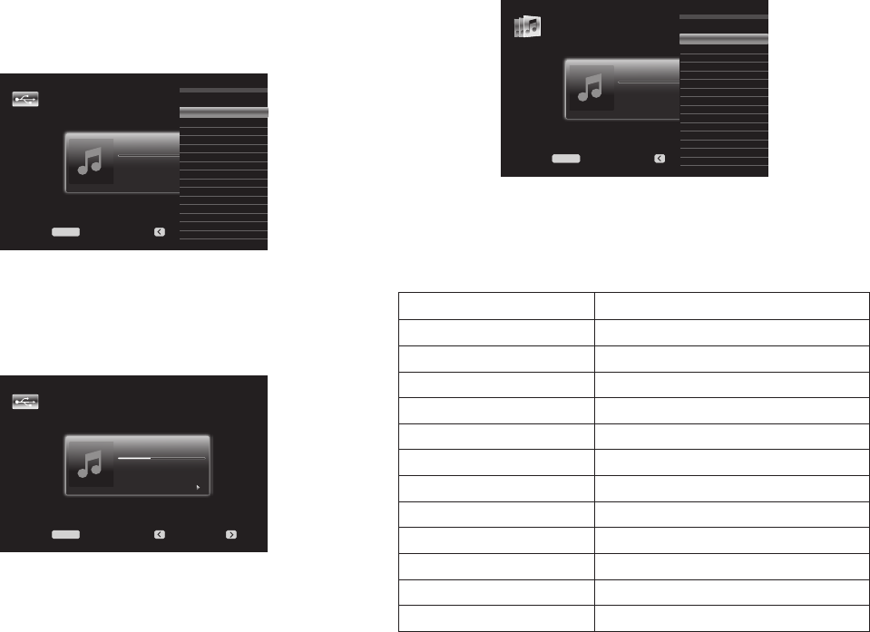
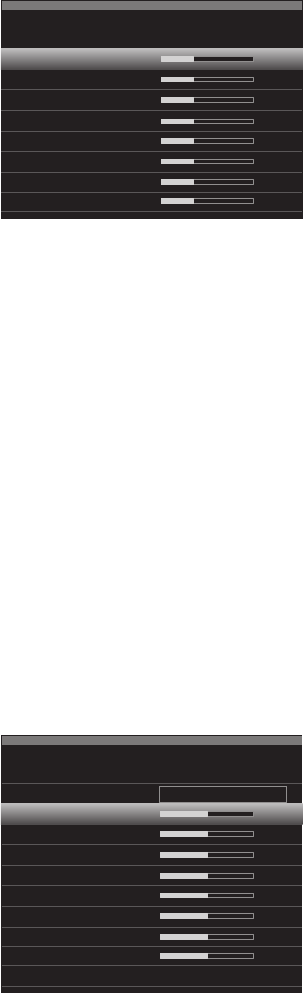
Manual Speaker Setup
If you have already run the EzSet/EQ process as explained in
Configure the AVR for Your
Speakers
, on page 25, the AVR saved the results. To fine-tune the EzSet/EQ results, or to
configure the AVR from scratch, select Manual Setup. A screen similar to the one shown
below will appear.
Sub
Number of Speakers
Level Adjust
Crossover (Size)
Distance
Sub Mode:
Reset
Manual Speaker Setup
NOTE: All of the speaker setup submenus include the Back option. To save the current
settings, select the Back option.
To reconfigure the speakers from scratch, select the Reset option.
For best results, adjust the submenus in this order: Number of Speakers, Crossover (Size),
Sub Mode, Distance and Level Adjust.
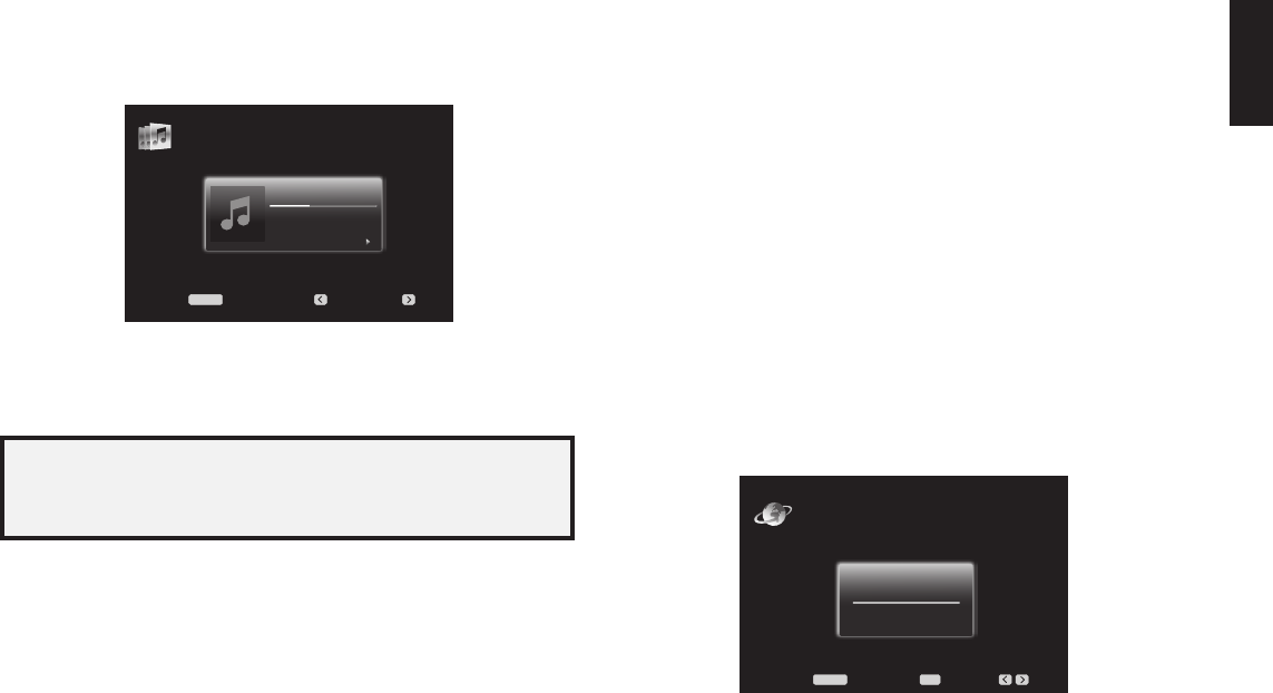
Number of Speakers
This selection lets you program the correct setting for each speaker group. The settings
in this menu affect the remainder of the speaker setup process and the availability of
various surround modes at any time.
Select ON when the speakers are present in the system; select OFF for positions where
no speakers are installed. The Front Left & Right setting is always ON and may not be
disabled.
Front Left & Right
Center
Surr. Left & Right
Assigned AMP
Sub
Manual Speaker Setup
Number Of Speakers: 7.1
On
On
On
Surr. Back
Any changes will be reflected in the total Number Of Speakers displayed at the top of
the screen.
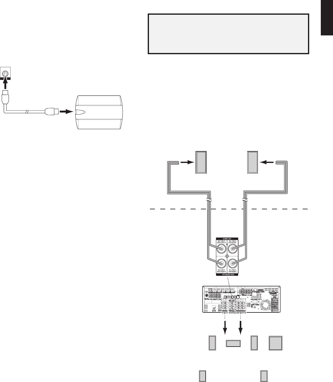
The Assigned AMP setting includes four options:
Surround Back:• Select the Surr. Back option if your main system is a 7.1-channel
system and you are using surround back left and surround back right speakers.
Zone 2:• Select the Zone 2 option if your main system is a 5.1-channel system and
you want to use the Assigned Amp speaker outputs to power speakers in Zone 2. See
Install a Multizone System
, on page 21, for more information.
Front Height:• Select the Front Height option if your main system is a 7.1-channel
system and you are using Front Height speakers with Dolby Pro Logic IIz.
Off:•Select Off if you have not connected speakers to the Assigned Amp speaker
outputs.
NOTE: When you set Assigned AMP to “Zone 2,” the speakers connected to the Assigned
Amp outputs will not be configured during the EzSet/EQ process. Configure the speakers
manually, as explained below.
When you have finished, select the Back option or use the Back/Exit button.
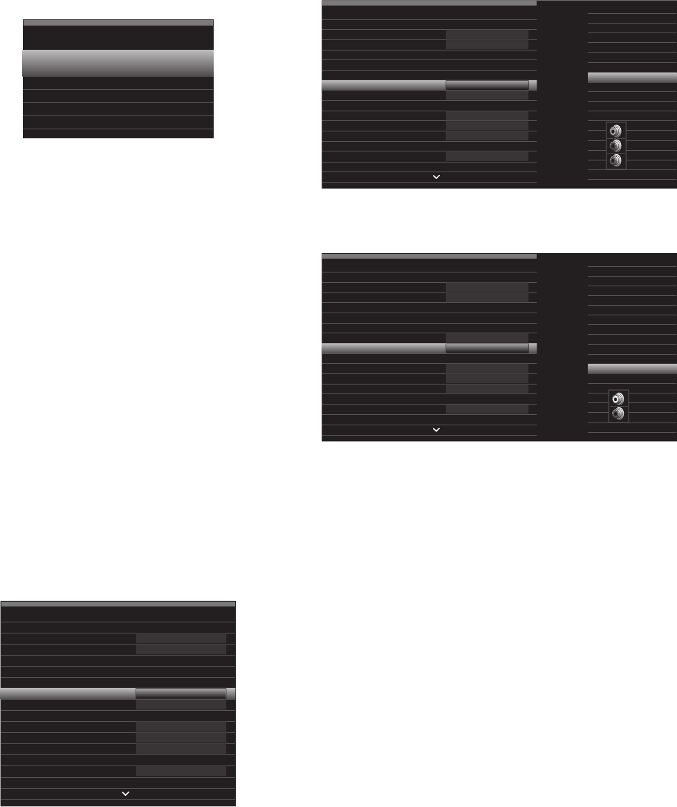
Crossover (Size)
After you return to the Manual Speaker Setup menu, navigate to the Crossover (Size) line
and press the OK button to display the Adjust Crossover Frequencies menu.
Front Left & Right
Center
Surr. Left & Right
Surr. Back L & R
Sub Size
Reset Crossover
Manual Speaker Setup
Adjust Crossover Frequencies
12 inch
80 Hz
80 Hz
100 Hz
100 Hz
The AVR will display only those speaker groups you set to On in the Number of Speakers
menu.
Refer to Table A3 for each speaker’s crossover frequency.
For each speaker group, select one of these eight crossover frequencies: Large, 40Hz,
60Hz, 80Hz, 100Hz, 120Hz, 150Hz or 200Hz. If the speaker’s crossover frequency is
below 40Hz, select the first option, “Large.” This setting doesn’t refer to the speaker’s
physical size but to its frequency response, which is also called “full range.”
Specify the size of the subwoofer’s transducer as 8, 10, 12 or 15 inches. The AVR always
sets the subwoofer crossover to 100Hz but uses the transducer size for equalization.
Write down the settings in Table A6 in the Appendix.
When you have finished entering the settings, select Back or press the Back/Exit
button.
Sub Mode
Move the cursor to the Sub Mode line. This setting depends upon the Crossover setting
you selected for the front left and right speakers.
If you set the front speakers to a numeric crossover frequency, the subwoofer setting •
will always be SUB. All low-frequency information will always be sent to the subwoofer.
If you don’t have a subwoofer, either upgrade to full-range front left and right speakers
or add a subwoofer at the earliest opportunity.
If you set the front speakers to LARGE, select one of the three following settings for •
the subwoofer:
L/R+LFE: This setting sends all low-frequency information to the subwoofer,
including a) information that would normally be played through the front left and
right speakers and b) the special low-frequency effects (LFE) channel information.
OFF: Select this setting when no subwoofer is in use. All low-frequency information
will be sent to the front left and right speakers.
LFE: This setting plays low-frequency information contained in the left and right
program channels through the front left and right speakers, and directs only the
LFE-channel information to the subwoofer.
0295CSK - HK (x65Series) AVR3650_365_2650_265 CORE OM, WORK18 danny.indd 3701/07/11 11:34:08
AVR
38
Manual Speaker Setup
Set the Speaker Distances
As described above in Step Two, when you measured the distances from each of your
speakers to the listening position, your AVR provides an adjustment that compensates
for the different distances so that the sound from each speaker will reach the listening
position at the proper time. This process will improve the clarity and detail of the sound.
On the Manual Speaker Setup menu, move the cursor to the Distance line and press the
OK button to display the Adjust Speaker Distance menu.
Front Left
Center
Front Right
Surround Right
Surround Back Right
Surround Back Left
Surround Left
Sub
Manual Speaker Setup
Adjust Speaker Distance
10.0 ft
Enter the distance from each speaker to the listening position that you measured in Step
Two and recorded in Table A4 in the Appendix (see page 46). Select a speaker, then use
the Left/Right buttons to change the measurement. You can enter distances between 0
and 30 feet (9.1m). The default distance for all speakers is 10 feet (3m).
The default unit of measurement is feet. To change the unit to meters, return to the main
AVR menu. Select the System Settings menu, then scroll down to the General Setup
section and select the Unit of Measure line. Press the OK button to change the setting.
NOTE: If you set the Assigned AMP channels to Zone 2, you will not be able to adjust
their delay settings.
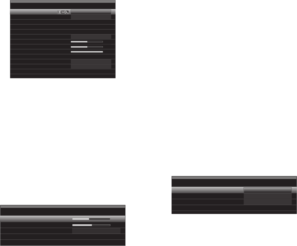
Step Four – Setting Channel Output Levels Manually
For a conventional stereo receiver, a simple balance control adjusts the stereo imaging
by varying the relative loudness of the left and right channels. In a home theater system
with up to seven main channels plus a subwoofer, achieving proper imaging becomes
both more critical and more complex. The goal is to ensure that each channel is heard
at the listening position with equal loudness (when signals of equal loudness are played
through them).
Your AVR’s EzSet/EQ calibration can handle this critical task for you simply and
automatically. However, the AVR’s Adjust Speaker Levels menu allows you to calibrate
the levels manually, either using the system’s built-in test tone or while playing source
material.
Press the Setup button to display the menu system, and then navigate to the Speaker
Setup line. Press the OK button to display the Speaker Setup menu. Select Manual Setup,
press the OK button, and then navigate to the Level Adjust line. Press the OK button to
display the Adjust Speaker Levels menu.
Front Left
Center
Front Right
Surround Right
Surround Back Right
Surround Back Left
Surround Left
Sub
Reset Levels
Manual Speaker Setup
Adjust Speaker Levels
0 dB
Test ToneOff
All of the system’s speakers will appear with their current level settings. You can adjust
each speaker’s level between –10dB and +10dB in 1dB increments.
While making adjustments, you can measure the channel levels in one of these ways:
Preferably, use a handheld SPL meter set to the C-weighting, slow scale. Adjust each •
speaker so that the meter reads 75dB when the AVR’s built-in test noise is playing.
By ear. Adjust the levels so that the test tone sounds equally loud to you when it plays •
through each speaker.
To set your levels using the AVR’s internal test tone, select the menu’s Test Tone line and
use the OK button to select between Auto and Manual:
Auto:The test tone will automatically circulate to all speakers, as indicated by the
highlight bar. Use the Left/Right buttons to adjust the level for any speaker when the
test tone is paused there. Use the Up/Down buttons to move the cursor to another line,
and the test tone will follow the cursor. To stop the test tone, use the Up/Down buttons to
move the cursor out of the screen’s speaker listings area.
Manual: The test tone will stay on the current speaker until you use the Up/Down buttons
to move it to another speaker. Use the Left/Right buttons to adjust the level for the speaker
through which the test tone is playing.
If you are using an external source to set your output levels, set Test Tone to Off, use
the Up/Down buttons to navigate to each speaker, and use the Left/Right buttons to
adjust the speaker’s level while the source plays. NOTE: If you are using a handheld SPL
meter with external source material, such as a test disc or an audio selection, play it and
adjust the AVR’s master volume control until the meter measures 75dB. Then adjust the
individual speaker levels.
Reset Levels: To reset all levels to their factory defaults of 0dB, scroll down to this line
at the bottom of the menu and press the OK button.
When you have finished adjusting the speaker levels, record the settings in Table A3 in
the Appendix. Then select the Back option or press the Back/Exit Button.
Notes on Setting Speaker Volumes in Home Theater Systems:
While setting your system’s individual speaker volume levels is ultimately up to your
personal taste, here are some ideas you may find helpful:
For films and video-music programs, your overall goal should be to create an •
enveloping, realistic sound field that draws you into the film or music program without
drawing your attention away from the action on the screen.
For multichannel music recordings, some music producers will create a sound field •
that places the musicians all around you; others will create a sound field that places
the musicians in front of you, with more subtle ambience in the surround speakers (as
you would experience in a concert hall).
In most 5.1-channel and 7.1-channel film soundtracks, the surround speakers are •
not intended to be as loud or as active as the front speakers. Adjusting the surround
speakers so they are always as loud as the front speakers could make dialogue difficult
to understand and will make some sound effects sound unrealistically loud.
Notes on Setting Subwoofer Volume:
Sometimes the ideal subwoofer volume setting for music is too loud for films, while the •
ideal setting for films is too quiet for music. When setting the subwoofer volume, listen
to both music and films with strong bass content and find a “middle ground” volume
level that works for both.
If your subwoofer always seems too loud or too quiet, you may want to place it in a •
different location. Placing the subwoofer in a corner will always tend to increase its
bass output, while placing it away from any walls or corners will always tend to lessen
its bass output.
0295CSK - HK (x65Series) AVR3650_365_2650_265 CORE OM, WORK18 danny.indd 3801/07/11 11:34:08
AVR
39
ENGLISH
Manual Speaker Setup, System Settings
Listening in Zone 2
With the multizone system in use, you may enjoy an exciting 5.1-channel home theater
presentation in the main listening area, while others listen to the same program or an
entirely different source in another room. See
Install a Multizone System
, on page 21, for
installation information.
You control the AVR’s multizone system from the on-screen Zone 2 menu. Press the
Setup button, and use the Up/Down buttons to navigate to the Zone 2 line. Press the OK
button to display the Zone 2 menu.
Zone 2
Status:
Source:
Volume:
Assigned AMP:
Off
FM Radio
Zone 2
Status: This line lets you turn Zone 2 on or off.
Source: This line lets you select the source input for Zone 2. You may select a different
source from the one currently operating in the main listening area. However, if the same
source has been selected for both the main listening area and Zone 2, listeners in both
areas will hear the same content.
NOTE: Only analog audio sources, including The Bridge IIIP and USB devices, are
available to the multizone system. To hear digital devices such as a CD player in
Zone 2, follow these steps:
In addition to making a digital audio connection, connect the source device’s analog 1.
audio outputs to the AVR. Make a note in Table A5 on page 47 to record which set of
analog inputs you used.
In the Info menu, scroll down to the Zone 2 Audio setting and select the analog audio 2.
input. (Leave the Audio Input From Source set to the digital input.)
Volume:Highlight this line, and use the Left/Right buttons to control the volume in
Zone 2.
Assigned AMP:This line lets you assign the Assigned AMP channels to “Zone 2”
for multizone operation (see
Number of Speakers
, on page 37). When this line is set
to Zone 2, you may configure the main listening room for only up to 5.1 channels.
To operate the multizone system using the main remote, slide the Zone Select Switch at
the bottom of the remote to the “2” position.
AVR 3650/AVR 365 only: To select a zone using the Zone 2 remote, press the Zone
Selector, and the Zone Indicator light will turn green when the remote is set to operate
Zone 1 or red to operate Zone 2.
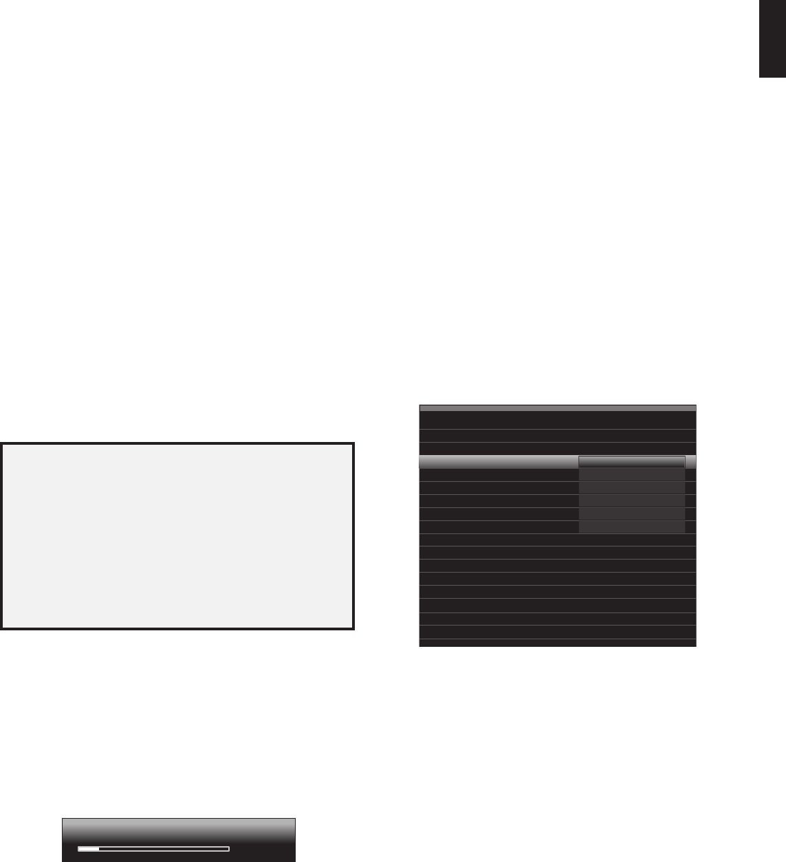
System Settings
The AVR’s System Settings menu lets you customize in what way many of the AVR’s
features operate. Press the Setup button and navigate to the System line. Press the OK
button to display the System Settings menu.
System Settings
Front Panel Settings
Front Panel Dimmer:
On 100%
dB
On
On
On
Auto
On
Off
HDMI Settings
HDMI Audio to TV:
HDMI Control:
Audio Return Channel:
Power Control:
TV Control:
General A VR Settings
Network Settings
Volume Units:
Volume Default:
Volume Default Level
System Settings
Unit of Measure:
Language:
Dolby Vol. Calibration:
RS232 Control:
Feet (ft)
English
Off
24-02-2011 03
Medium
3 seconds
30 seconds
5 minutes
10 minutes
Menu Appearance
Menu Transparency:
Volume/Status Messages:
Menus:
Setup and Slide-In Menus:
Screen Saver:
System Info
Software Version:
Upgrade Software:
Front-Panel Dimmer: This control sets the brightness of the AVR’s front-panel message
display. Select from 100%, 50%, 25% or Off. The light inside the Volume Control will go
out when the display is partly or fully dimmed, but the Power Indicator will always remain
lit to remind you that the AVR is powered on.
HDMI Settings
HDMI Audio to TV: This setting determines whether HDMI audio signals are passed
through the HDMI Monitor Out connector to the video display. In normal operation, leave
this setting at Off, as audio will be played through the AVR. To use the TV by itself, without
the home theater system, turn this setting to On. In this case you will need to mute the
TV’s speakers (or switch the setting to Off) when using the AVR for audio.
HDMI Control: This setting allows the communication of control information among the
HDMI devices in your system. Turn this setting to On to allow control communication
between the HDMI devices; turn the setting to Off to forbid control communication.
Audio Return Channel: Selecting “Auto” will send audio from the TV to the AVR via the
HDMI Audio Return Channel (ARC) connection (which is in the HDMI cable connecting
the AVR to the TV). The TV source’s “Audio Input from Source” will be automatically
reassigned to the HDMI ARC connector. This way, whenever you’re watching a source
that is connected directly to your TV (such as an Internet connection), you can listen to
the sound through the AVR.
Power Control: This setting links the power on/off functions of the AVR to those of a TV
connected to its HDMI Monitor Out connector. When Power Control is set to On, turning
the TV’s power off will automatically put the AVR into the Standby mode; turning the TV’s
power on will automatically turn the AVR on. NOTE: The connected TV must support the
HDMI System Standby CEC (Consumer Electronics Control).
TV Control: This setting extends some audio-control functions between the AVR and a TV
connected to its HDMI Monitor Out connector. When TV Control is set to On, if the TV is set
to use external speakers, the TV’s internal speakers will mute, and you can use the TV’s
remote to control the AVR’s volume up/down and mute functions. If the TV is set to use
its internal speakers, the AVR’s output will automatically mute. NOTE: The connected TV
must support the HDMI Remote Control/System Audio Control CEC (Consumer Electronics
Control).
0295CSK - HK (x65Series) AVR3650_365_2650_265 CORE OM, WORK18 danny.indd 3901/07/11 11:34:09
AVR
40
System Settings
General AVR Settings
Network Settings: Select this to set up your AVR for connection to your home network.
Network Settings
ID#:
Network Settings:
IP Address:
Subnet Mask:
00 00 00 00 A0 A0
Manual
000 . 000 . 000 . 000
000 . 000 . 000 . 000
000 . 000 . 000 . 000
000 . 000 . 000 . 000
000 . 000 . 000 . 000
Not Connected
Gateway:
Primary DNS:
Secondary DNS:
Network Status:
Apply & Save – A VR will Enter Standby
ID #: This line is informational only and identifies the AVR to other devices on your •
home network and the Internet for www.radioharmankardon.com.
Network Settings: Since most networks use automatic IP address settings, in most •
cases you can set Network Settings to Automatic. If you are required to use a static IP
address and network settings, you must obtain these settings from your ISP or network
administrator. Use the OK button to set this line to “Manual.” The following settings
will become active: IP Address, Subnet Mask, Gateway, Primary DNS, Secondary DNS.
Use the Number buttons to make the entries for all of these settings. When you have
finished, select Apply & Save, and press the OK button. The AVR will enter the Standby
mode. When you turn the AVR back on, it will attempt to connect to the network using the
settings you entered. If the AVR cannot connect to the network using the manual settings,
contact your ISP or network administrator for assistance.
Network Status: This line indicates the AVR’s current network-connection status •
(Connected/Not Connected).
Apply & Save: Any time you make a change in any of the Network settings, the Apply & •
Save line will become available. Select this line and press the OK button. The AVR will
go into the Standby mode. After you turn the AVR back on, the new network settings
will be in effect. IMPORTANT: You must select Apply & Save for your network
settings to take effect.
NOTE: If you have trouble connecting to the network at any time, cycle the AVR into
the Standby mode, and then turn it back on.
Volume Units: This setting lets you select whether the AVR displays the volume level in
the conventional decibel scale or on a numeric scale from 0 to 100. When the decibel
scale is used, 0dB is the maximum recommended volume, with lower volumes displayed
as negative values. (-90dB – +10dB). The decibel scale is the default setting.
Volume Default and Volume Default Level: These two settings are used together to
program the volume level when you turn on the AVR. Set Volume Default to On, and then
set the Volume Default Level to the desired turn-on volume. When Volume Default is set
to Off, the AVR will turn on at the last-used volume setting from the previous listening
session.
Unit of Measure:Adjusts the speaker-distance settings for Manual Speaker Setup.
Select between meters and feet.
Language: Select the preferred language for the AVR’s on-screen menus and displays:
English, French, Spanish, German, Italian or Russian.
Dolby Volume Calibration: This setting determines the Dolby Volume calibration, as
described in
Dolby Volume Calibration
, on page 28. Refer to that section for details about
setting the calibration.
RS232 Control:If you have connected the AVR to an external control system via its
RS-232 port, set this line to On to enable the AVR to be controlled by the external control
system. Refer to the control system’s documentation for details.
Menu Appearance
Menu Transparency: This selection lets you determine whether video programs will be
visible when the menu system is in use. Select Normal for a fully transparent background,
Medium for partial transparency or Opaque to completely block video programs while
menus are on screen.
Volume/Status Messages: When the AVR is turned on, the volume is adjusted, the source
is changed or a change in the input signal is detected, a status message will be displayed
on the TV screen. Select how long the message remains visible, from 2 to 10 seconds,
with a default of 3 seconds. Select “Off” if you do not wish to see the status messages on
the TV screen (they will still appear on the AVR’s front-panel message display).
Menus: This setting governs how long the Surround Modes, Video Modes and Audio
Effects menus remain visible after the last adjustment: 5 seconds, 10 seconds, 30
seconds, 1 minute or 5 minutes. Select “No Time-Out” to view the menus indefinitely,
but this setting is not recommended, due to the danger of “burn-in” on some video
displays.
Setup and Slide-In Menus: This setting determines how long the setup menus (Main
Menu, Speaker Setup Menu, Zone 2 Menu, all slide-in menus) remain visible after the last
adjustment. Select a time-out period of 5, 10 or 15 (the default) minutes, or no time-out,
which leaves the menus on screen until manually cleared. A time-out period avoids the
possibility of burn-in damage to plasma or CRT displays.
Screen Saver:Program a time-out period for no activity (with no menus displayed)
before the AVR’s built-in screen saver begins. Select a period of 5 minutes, 10 minutes,
20 minutes, 30 minutes or 1 hour, or turn off the screen saver. A time-out period avoids
the possibility of burn-in damage to plasma or CRT displays.
System Info
Software Version: This line is informational only. From time to time, Harman Kardon
engineers may release software upgrades that improve your AVR’s performance
or add features. If you are experiencing difficulties with the AVR, a customer-service
representative may ask for the software version of your product to determine whether a
later upgrade is available.
Upgrade Software: If a software upgrade is released for your AVR, installation instructions
will be available in the Product Support section of the Web site or from Harman Kardon
customer service. At that time, you may access this submenu to install the upgrade
software.
IMPORTANT:During a system upgrade, do not power off the AVR or use any of its
controls. Doing so could permanently damage the AVR.
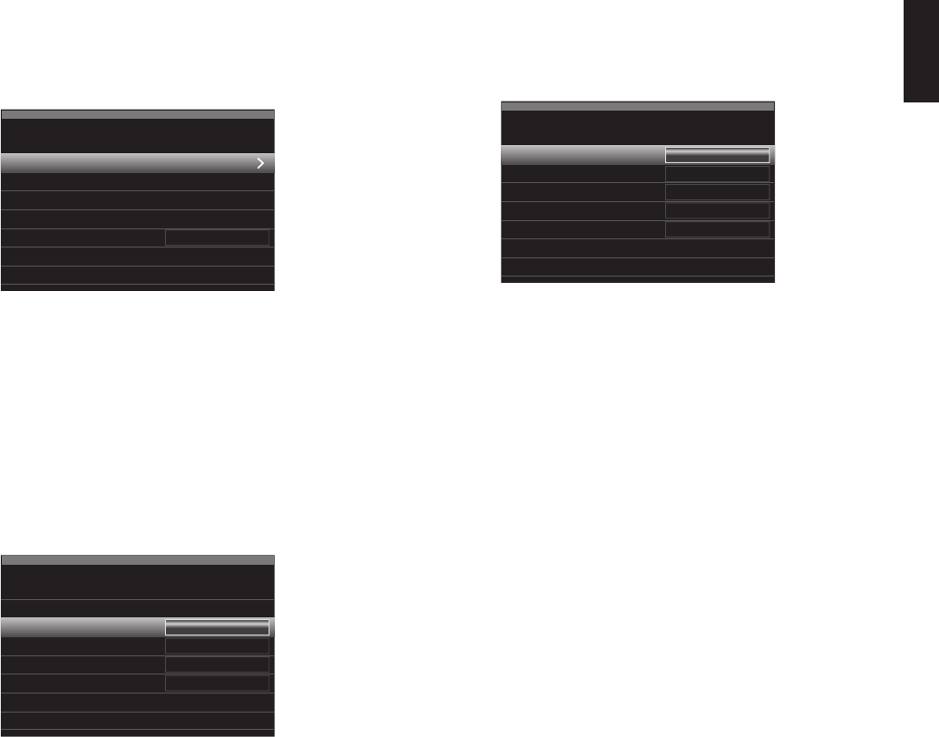
Settings Lock
Settings Lock prevents the Setup Source, Speaker Setup and System settings menus
from being inadvertently changed. With Settings Lock set to On, the screen shown below
will appear whenever someone attempts to access a setting in one of those menus.
The settings lock is currently On.
In order to access the settings,
please select ‘Settings lock Off’.
Settings Lock
Cancel
Settings Lock Off
Select “Settings Lock Off” to access the settings or “Cancel” if the setting was accessed
inadvertently. NOTE: If you select “Settings Lock Off,” you will need to turn the Settings
Lock back on via the Settings Lock menu.
0295CSK - HK (x65Series) AVR3650_365_2650_265 CORE OM, WORK18 danny.indd 4001/07/11 11:34:10
AVR
41
ENGLISH
Advanced Remote Control Programming
Advanced Remote Control Programming
Remote Channel-Control Punch-Through
The punch-through feature allows you to operate one component while setting certain
groups of controls to operate another component. For example, while using the AVR
controls for surround modes and other audio functions, you may also use the remote to
operate the transport controls of your Blu-ray Disc player. Or while using the remote to
control video functions on your TV, you may also use the remote to change channels on
your cable box.
To program punch-through control while operating any device:
For three seconds press and hold the Source Selector button for the main device the 1.
remote will be operating. The Source Selector will light up, go dark and then light up
again, indicating the remote is in Program mode and that you may release the button.
Select the type of punch-through programming.2.
For channel-control punch-through, press the Channel Up button.a)
To program transport-control punch-through, press the Play transport-control b)
button.
Press the Source Selector button for the device whose channel or transport controls 3.
you will use while operating the device selected in the first step. The Source Selector
button will flash to confirm.
For example, to watch the TV while changing channels using the cable box, press and
hold the TV button until it lights. Then press the Channel Up button, followed by the Cable/
SAT button.
To undo punch-through programming, follow the same steps as above, but press the
same Source Selector button in Steps 1 and 3.
NOTE: The Volume and Mute controls are always dedicated to the AVR.
Programming Macro (Activity) Commands
In addition to their normal functions, you can also use the 0 – 9 Number buttons and AVR
Power On button to store Macro (Activity) commands – up to 11 of them. Each Macro
can send out up to 19 commands at one time from a single button push. Any AVR remote
control button’s function from any mode (except the Back/Exit button, the Light button,
and the Activity button) can be programmed into a Macro.
NOTE: Use caution when programming complicated Macros. It isn’t possible to program
a pause or delay before sending additional commands after a “Power On” command, and
the component may not be ready to respond to commands immediately after powering
on.
To program a Macro:
To enter the Programming mode, simultaneously press and hold the Activity button and 1.
the Number button or AVR Power On button to which you want to assign the Macro.
Press in up to 19 commands that you want stored in that Macro button. During each 2.
successive button selection, the Source Selector button LED will blink once. Press the
Source Selector button for each device (or Setup button for the AVR itself) before you
enter individual commands. This step counts as one of the 19 commands allowed for
each Macro.
You can select functions from another mode by first pressing the corresponding Source •
Selector button and then the buttons where those functions are located within that
mode. Pressing a Source Selector button also counts as one command.
For power on, press the AVR or Device Power On button. •
For power off, press the AVR or Device Power Off button. •
Press the Activity button to end the programming process. The last Source Selector 3.
button (or the Setup button) will flash three times.
It isn’t possible to “edit” a command within a Macro. To erase the Macro:
Press and hold the Activity Button and the button into which you programmed the 1.
Macro until the Source Selector or Setup button lights up.
Press the Activity button to erase the Macro.2.
To execute a Macro:
Press the Activity button, then press the button into which you programmed the Macro.
IMPORTANT:Keep the remote aimed at the components until all of the Macro
commands have been executed. The remote can take up to 10 seconds to send out 19
Macro commands.
Recording
Two-channel analog and digital audio signals, as well as composite video signals, are
normally available at the appropriate recording outputs. To make a recording, connect
your audio or video recorder to the appropriate AVR output connectors as described in
the Making Connections section, insert blank media in the recorder and make sure the
recorder is turned on and recording while the source is playing. Refer to the recording
device’s instructions for complete information about making recordings.
NOTES:
The AVR does not convert analog signals to digital or vice versa.1.
HDMI and component video sources are not available for recording.2.
Please make certain that you are aware of any copyright restrictions on any material 3.
you record. Unauthorized duplication of copyrighted materials is prohibited by law.
Sleep Timer
The sleep timer sets the AVR to play for up to 90 minutes and then turn off
automatically.
Press the Sleep button on the remote, and the time until turn-off will be displayed.
Each additional press of the Sleep button increases the play time by 10 minutes, with a
maximum of 90 minutes. The SLEEP OFF setting disables the sleep timer.
When the sleep timer has been set, the front-panel display will automatically dim to half
brightness.
If you press the Sleep button after the timer has been set, the remaining play time will be
displayed. Press the Sleep button again to change the play time.
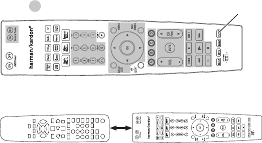
Updating Your Network Software
From time to time, updates to your network sofwtare may become available. To check for
and download these updates:
After the AVR has connected to your network, press the remote’s Internet Radio source 1.
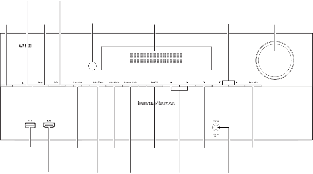
button.
On the AVR front panel, simultaneously press and hold the Surround Modes and Back/2.
Exit buttons.
Message
Display
Surround
Modes
Button
OK
Button
Back/Exit
Button
Watch the front-panel Message Display for a message that the unit is checking for 3.
software updates. When the message appears, release the buttons.
0295CSK - HK (x65Series) AVR3650_365_2650_265 CORE OM, WORK18 danny.indd 4101/07/11 11:34:11
AVR
42
Advanced Remote Control Programming
If the message indicates that an update is available, press the front-panel OK button 4.
to begin the update.
During the update a progress bar and status messages will appear on the Message 5.
Display. Do not touch any controls on the AVR and do not interrupt the network
connection during the update.
When the update is completed the AVR will automatically power off, and after five 6.
seconds will automatically power back on. Once the AVR turns back on it’s ready to
use.
Resetting the Remote
To reset the remote to its factory default condition, simultaneously press and hold the TV
Source Selector button and the “0” Number button. When the TV Source button relights,
enter the code “333.” When the TV button goes out, and all of the Source Selector buttons
flash, the remote control will be reset.
Processor Reset
If the AVR behaves erratically after a power surge, first turn off the rear-panel Main
Power switch and unplug the AC power cord for at least 3 minutes. Plug the cord back
in and turn the receiver on. If this procedure doesn’t help, reset the AVR’s processor as
described below.
NOTE:A processor reset erases all user configurations, including video resolution,
speaker and level settings, and tuner presets. After a reset, reenter all of these settings
from your notes in the Appendix worksheets.
To reset the AVR’s processor:
Press the front-panel Standby/On switch to place the unit in the Standby mode (the 1.
Power Indicator will turn amber).
Press and hold the front-panel OK button for at least 5 seconds until the RESET 2.
message appears on the front-panel Message Display.
NOTE: After performing a processor reset, wait at least 1 minute before pressing any
Source Selector buttons.
If the receiver does not function correctly after a processor reset, contact an authorized
Harman Kardon service center for assistance. Authorized service centers may be located
by visiting our Web site at www.harmankardon.com.
0295CSK - HK (x65Series) AVR3650_365_2650_265 CORE OM, WORK18 danny.indd 4201/07/11 11:34:11
AVR
43
ENGLISH
Troubleshooting
SymptomCauseSolution
Unit does not function when Main Power switch is turned
on
No AC power •Ensure that the power cord is plugged into a live AC •
power outlet
Check if the AC outlet is switch-controlled •
Front-panel Message display lights, but there’s no sound
or picture
Intermittent input connection •Dolby Digital EX •
Dolby Digital 2/2/.0 or .1, 3/2/.0 or .1 •
No sound from any speaker; PROTECT message appears
on Message display
Amplifier is in protection mode due to possible short •
circuit
Dolby Digital Plus via HDMI connection (source device •
decodes to Dolby Digital when a coaxial or optical
connection is used)
No sound from center or surround speakersIncorrect surround mode •
Program material is monophonic •
Incorrect speaker configuration •
Program material is stereo •
Select a surround mode other than stereo •
Mono programs contain no surround information •
Check the speaker configuration in the setup menu •
The surround decoder may not create center- or •
surround-channel information from nonencoded
programs
Unit does not respond to remote control commandsWeak batteries in remote •
AVR not selected •
Remote sensor is obscured •
Change batteries in remote •
Press the Setup/AVR button •
Ensure that the AVR’s front-panel remote sensor is in •
the line of sight of the remote
Intermittent buzzing in tunerLocal interference •Move the AVR or antenna away from computers, •
fluorescent lights, motors or other electrical appliances
(AVR 3650/AVR 365 only): Surround-back speaker
settings cannot be accessed, and the test tone does not
play through the surround back speakers
Multi-zone operation has been selected/Assigned AMP •
channels have been assigned to Zone 2
Use the Speaker Setup menu to reassign the Assigned •
AMP to the surround back left and right channels
(AVR 3650/AVR 2650 only): The SIRIUS Preview
Channel (001) is silent
SIRIUS tuner is not connected •
SIRIUS antenna is in an improper location •
SIRIUS signal requires a refresh •
Ensure that SIRIUS tuner is properly connected •
Re-locate the SIRIUS antenna according to the •
recommendations in the SIRIUS tuner’s instruction
manual. For further help, visit
www.siriusradio.com
Visit www.siriusradio.com •
Unable to activate remote control Programming modeSource Selector button is not held for at least 3 •
seconds
Be sure to hold the Source Selector button for at least •
3 seconds
Remote buttons light, but AVR does not respondRemote is in Zone 2 mode •Slide Zone Selector switch to the Zone 1 position. •
Unable to establish network connectionAVR network programming requires rebooting •Cycle the AVR into the Standby mode, and then turn it •
on again
Additional information on troubleshooting possible problems with your AVR and installation-related issues may be found in the list of “Frequently Asked Questions,” which is
located in the Product Support section of our Web site: www.harmankardon.com
0295CSK - HK (x65Series) AVR3650_365_2650_265 CORE OM, WORK18 danny.indd 4301/07/11 11:34:11
AVR
44
Specifications
Audio Section
Stereo power:AVR 3650/AVR 365: 110W per channel, two
channels driven @ 8 ohms, 20Hz – 20kHz,
<0.09% THD
AVR 2650/AVR 265: 95W per channel, two
channels driven @ 8 ohms, 20Hz – 20kHz,
<0.09% THD
Multichannel power:AVR 3650/AVR 365: 110W per channel, two
channels driven @ 8 ohms, 20Hz – 20kHz,
<0.09% THD
AVR 2650/AVR 265: 95W per channel, two
channels driven @ 8 ohms, 20Hz – 20kHz,
<0.09% THD
Input sensitivity/impedance:200mV/47k ohms
Signal-to-noise ratio (IHF-A):100dB
Surround system adjacent channel
separation:
Dolby Pro Logic/DPLII: 40dB
Dolby Digital: 55dB
DTS: 55dB
Frequency response (@ 1W):10Hz – 130kHz (+0dB/–3dB)
High instantaneous current capability
(HCC):
±35 amps
Transient intermodulation distortion
(TIM):
Unmeasurable
Slew rate:40V/µsec
FM Tuner Section
Frequency range:87.5 – 108.0MHz
Usable sensitivity IHF:1.3µV/13.2dBf
Signal-to-noise ratio (mono/stereo):70dB/68dB
Distortion (mono/stereo):0.2%/0.3%
Stereo separation:40dB @ 1kHz
Selectivity (±400kHz):70dB
Image rejection:80dB
IF rejection:90dB
AM Tuner Section
Frequency range:520 – 1710kHz (AVR 3650/AVR 2650)
522 – 1620kHz (AVR 365/AVR 265)
Signal-to-noise ratio:45dB
Usable sensitivity (loop):500µV
Distortion (1kHz, 50% mod):0.8%
Selectivity (±10kHz):30dB
Video Section
Television format:NTSC (AVR 3650/AVR 2650);
PAL (AVR 365/AVR 265)
Input level/impedance:1Vp-p/75 ohms
Output level/impedance:1Vp-p/75 ohms
Video frequency response (composite
video):
10Hz – 8MHz (–3dB)
HDMI:Version 1.4a with 12-bit Deep Color
General Specifications
Power requirement:120V AC/60Hz (AVR 3650/AVR 2650);
220V – 240V AC/50Hz – 60Hz (AVR 365/
AVR 265)
Power consumption:<0.5W (standby);
480W maximum (AVR 3650/AVR 365);
420W maximum (AVR 2650/AVR 265)
Dimensions (W x H x D): 17-5/16" x 6-1/2" x 17-1/8"
(440mm x 165mm x 435mm)
Weight(AVR 3650/AVR 365): 27.25 lb (12.4kg)
(AVR 2650/AVR 265): 24.4 lb (11.1kg)
Depth measurement includes knobs, buttons and terminal connections.
Height measurement includes feet and chassis.
Specifications
0295CSK - HK (x65Series) AVR3650_365_2650_265 CORE OM, WORK18 danny.indd 4401/07/11 11:34:12
Left/Right Surround Back or Left/Right Front Height
Speakers Crossover Frequency
100Hz
Subwoofer ModeLFE
Subwoofer Size10 inch
Front Left Level0dB
Center Level0dB
Front Right Level0dB
Surround Right Level0dB
Surround Back Right/Front Height Right Level0dB
Surround Back Left/Front Height Left Level0dB
Surround Left Level0dB
Sub Level0dB
Table A3 – Speaker/Channel Setting Defaults
Table A4 – Delay Setting Defaults
Speaker Position
Distance From Speaker to
Listening Position
Your Delay Settings
Position 1
Your Delay Settings
Position 2
Front Left10 feet (3 meters)
Center10 feet (3 meters)
Front Right 10 feet (3 meters)
Surround Right10 feet (3 meters)
Surround Left10 feet (3 meters)
Surround Back Right/Front Height Right 10 feet (3 meters)
Surround Back Left/Front Height Left10 feet (3 meters)
Subwoofer10 feet (3 meters)
A/V Lip Sync Delay (See Info Settings Menu)0mS
0295CSK - HK (x65Series) AVR3650_365_2650_265 CORE OM, WORK18 danny.indd 4601/07/11 11:34:12
AVR
47
ENGLISH
Appendix
Cable/Sat
Blu-ray
Disc
Media
Server
RadioTV
USB
(AVR 3650/
AVR 365)
NetworkGameAUXThe Bridge
DVR
(AVR 2650/
AVR 265)
Device TypeUSB
Surround Modes
Video InputN/AThe Bridge III
Audio InputUSBThe Bridge III
Resolution to Display
Adjust Lip Sync
Change NameN/AN/A
Audio Auto PollingN/AN/A
Zone 2 AudioUSBThe Bridge III
Dolby Volume
Table A5 – Source Settings
DefaultCable/Sat
Blu-ray
Disc
Media
Server
RadioTV
USB
(AVR 3650/
AVR 365)
NetworkGameAUXThe Bridge
DVR
(AVR 2650/
AVR 265)
Dolby VolumeSee Source
Tone ControlOn
Treble0dB
Bass0dB
LFE Trim0dB
MP3
Enhancer
Off
Table A6 – Audio Effects Settings
0295CSK - HK (x65Series) AVR3650_365_2650_265 CORE OM, WORK18 danny.indd 4701/07/11 11:34:12
AVR
48
Appendix
DefaultCable/Sat
Blu-ray
Disc
Media
Server
RadioTV
USB
(AVR
3650/
AVR 365)
NetworkGameAUX
The
Bridge
DVR
(AVR
2650/
AVR 265)
Video ModeOff
Brightness*50
Contrast*50
Color*50
Sharpness*50
Picture AdjustAuto Adjust
OverscanOff
Noise Reduction**Off
MPEG Noise Reduction**Off
Cross Color Suppressor**Off
Flesh Tone
Enhancement**
Off
Black Level**Off
Deinterlacing**Off
Film Mode Detect**Off
* Note: These settings are available only when the Video Mode is set to Custom.
** Note: These settings are displayed only when Advanced Video Settings is selected.
Table A7 – Video Modes Settings
DefaultCable/Sat
Blu-ray
Disc
Media
Server
RadioTV
USB
(AVR 3650/
AVR 365)
NetworkGameAUXThe Bridge
DVR
(AVR 2650/
AVR 265)
Auto Select
Logic 7 Movie or
native digital format
Virtual Surround
Harman virtual
speaker
Stereo7 CH Stereo
MovieLogic 7 Movie
MusicLogic 7 Music
GameLogic 7 Game
Center Width*3
Dimension*0
Panorama*Off
* Note: These settings are available only when Dolby Pro Logic II or IIx Music mode has been selected. Access these settings by selecting the Edit option.
Table A8 – Surround Modes
0295CSK - HK (x65Series) AVR3650_365_2650_265 CORE OM, WORK18 danny.indd 4801/07/11 11:34:12
AVR
49
ENGLISH
Appendix
Source InputDevice Type (if changed)Product Brand and Code Number
Cable/Sat
Blu-ray Disc
DVR (AVR 2650/AVR 265)
Media Server
TV
Game
AUX
Table A9 – Remote Control Codes
FeatureDefaultYour Settings
Front Panel DimmerOn 100%
HDMI Audio to TVOff
HDMI ControlOff
Audio Return ChannelOff
Power ControlOff
TV ControlOff
Network SettingsAutomatic
Volume UnitsdB
Volume DefaultOff
Volume Default Level–25dB
Unit of MeasureFeet (AVR 3650/AVR 2650): Meters (AVR 365/AVR 265)
LanguageEnglish
Dolby Volume Calibration0dB
RS232 ControlOff
Menu TransparencyMedium
Volume/Status Messages3 Seconds
Menus1 minute
Setup and Slide-In Menus5 minutes
Screen Saver10 minutes
Software VersionCheck your unit
Table A10 – System Settings
Source InputDefaultYour Settings
StatusOff
SourceCable/Sat
Volume–25dB
Assigned AMPSurround Back
Table A11 – Zone 2 Settings
0295CSK - HK (x65Series) AVR3650_365_2650_265 CORE OM, WORK18 danny.indd 4901/07/11 11:34:13
AVR
50
Appendix
Surround ModeDescriptionIncoming Bitstream or Signal
Dolby DigitalProvides up to five separate main audio channels and a dedicated low-frequency
effects (LFE) channel.
Dolby Digital 1/0/.0 or .1, 2/0/.0 or .1, 3/0/.0 or .1, •
2/1/.0 or .1, 2/2/.0 or .1, 3/2/.0 or .1
Dolby Digital EX (played as 5.1) •
Dolby Digital Plus decoded and delivered via coaxial or optical •
connection
Dolby Digital EXAn expansion of Dolby Digital 5.1 that adds a surround back channel that may be
played through one or two surround back speakers. May be manually selected
when a non-EX Dolby Digital stream is detected.
Dolby Digital EX •
Dolby Digital 2/2/.0 or .1, 3/2/.0 or .1 •
Dolby Digital PlusAn enhanced version of Dolby Digital encoded more efficiently, Dolby Digital Plus
has the capacity for additional discrete channels and for streaming audio from the
Internet, all with enhanced audio quality. Source material may be delivered via an
HDMI connection or decoded to Dolby Digital or PCM and transmitted via coaxial
or optical digital audio.
Dolby Digital Plus via HDMI connection (source device decodes to •
Dolby Digital when a coaxial or optical connection is used)
Dolby TrueHDDolby TrueHD is an expansion of MLP Lossless
™
audio, the same format used
on DVD-Audio discs. Dolby TrueHD adds the features found in Dolby Digital,
such as night mode settings, while delivering fully lossless audio that is a true
reproduction of studio master recordings.
Blu-ray Disc or HD-DVD encoded with Dolby TrueHD, delivered •
via HDMI
Dolby Digital StereoDelivers a two-channel downmix of Dolby Digital materials.Dolby Digital 1/0/.0 or .1, 2/0/.0 or .1, 3/0/.0 or .1, •
2/1/.0 or .1, 2/2/.0 or .1, 3/2/.0 or .1
Dolby Digital EX •
Dolby Pro Logic II
Mode Group
Analog decoder that derives five full-range, discrete main audio channels from
matrix surround-encoded or two-channel analog sources. Four variants are
available.
See below
Dolby Pro Logic II
Movie
Variant of Dolby Pro Logic II that is optimized for movie and television programs.Dolby Digital 2.0 or 2.1 •
Analog (two-channel) •
Tuner •
PCM (32kHz, 44.1kHz, 48kHz, 96kHz) •
Dolby Pro Logic II
Music
Variant of Dolby Pro Logic II that is optimized for music selections. Allows
adjustment of sound-field presentation in three dimensions:
Center Width (adjusts width of vocal soundstage) •
Dimension (adjusts depth of soundstage) •
Panorama (adjusts wraparound surround effect) •
Dolby Digital 2.0 or 2.1 •
Analog (two-channel) •
Tuner •
PCM (32kHz, 44.1kHz, 48kHz, 96kHz) •
Dolby Pro Logic II
Game
Variant of Dolby Pro Logic II that emphasizes use of the surround channels and
subwoofer for total immersion in the video gaming experience.
Dolby Digital 2.0 or 2.1 •
Analog (two-channel) •
Tuner •
PCM (32kHz, 44.1kHz, 48kHz, 96kHz) •
Dolby Pro Logic IIOriginal version of Dolby Pro Logic that steered a mono signal containing
information below 7kHz to the surround channels.
Dolby Digital 2.0 or 2.1 •
Analog (two-channel) •
Tuner •
PCM (32kHz, 44.1kHz, 48kHz, 96kHz) •
Dolby Pro Logic IIx
Mode Group
An expansion of Dolby Pro Logic II that adds a surround back channel which may
be played through one or two surround back speakers. The Dolby Pro Logic IIx
modes may be selected not only with Dolby Digital bitstreams, but thanks to the
AVR’s post-processor, they may also be used with some DTS bitstreams to add a
surround back channel to 5.1 modes.
See below
Table A12 – Surround Modes
0295CSK - HK (x65Series) AVR3650_365_2650_265 CORE OM, WORK18 danny.indd 5001/07/11 11:34:13
AVR
51
ENGLISH
Appendix
Table A12 – Surround Modes – continued
Surround ModeDescriptionIncoming Bitstream or Signal
Dolby Pro Logic IIx
Music
This mode is similar to Dolby Pro Logic II Movie, with an added surround back
channel.
Dolby Digital 2/0/.0 or .1, 2/2/.0 or .1, 3/2/.0 or .1, EX •
Analog (two-channel) •
Tuner •
PCM (32kHz, 44.1kHz, 48kHz, 96kHz) •
Dolby Pro Logic IIx
Music
This mode is similar to Dolby Pro Logic II Music, including the availability of center
width, dimension and panorama adjustments. Dolby Pro Logic IIx Music adds a
surround back channel.
Dolby Digital 2/0/.0 or .1, 2/2/.0 or .1, 3/2/.0 or .1, EX •
Analog (two-channel) •
Tuner •
PCM (32kHz, 44.1kHz, 48kHz, 96kHz) •
Dolby Pro Logic IIx
Game
This mode is similar to Dolby Pro Logic II Game, with the added benefit of a
surround back channel.
Dolby Digital 2/0/.0 or .1 •
Analog (two-channel) •
Tuner •
PCM (32kHz, 44.1kHz or 48kHz) •
Dolby Pro Logic IIzAn expansion of Dolby Pro Logic II that adds left and right front height channels
that are played through two front height speakers mounted above and outside of
the front left and right speakers.
Dolby Digital 2/0/.0 or .1, 2/2/.0 or .1, 3/2/.0 or .1, EX •
Analog (two-channel) •
Tuner •
PCM (32kHz, 44.1kHz, 48kHz, 96kHz) •
HARMAN virtual
speaker
Simulates 5.1 channels when only two speakers are present or a more enveloping
sound field is desired.
Dolby Digital •
Analog (two-channel) •
Tuner •
PCM (32kHz, 44.1kHz or 48kHz) •
DTS DigitalUsing a different encoding/decoding method than Dolby Digital,
DTS Digital also provides up to five discrete main channels, plus an
LFE channel.
DTS 1/0/.0 or .1, 2/0/.0 or .1, 3/0/.0 or .1, 3/1/.0 or .1, 2/2/.0 or •
.1, 3/2/.0 or .1
DTS-ES Matrix (played as 5.1) •
DTS-ES Discrete (played as 5.1) •
DTS-HDDTS-HD is a new high-definition audio format that complements the high-
definition video found on Blu-ray Disc and HD-DVD discs. It is transmitted using
a DTS core with high-resolution extensions. Even when only DTS 5.1 surround
sound is desired (or available, if the multizone system is in use), the higher
capacity of high-resolution discs serves up DTS at twice the bit rate used on
DVD-Video discs.
Blu-ray Disc or HD-DVD discs encoded with DTS-HD modes, •
delivered via HDMI connection
DTS-HD Master AudioDTS-HD Master Audio technology delivers bit-for-bit reproductions of the studio
master recording in up to 7.1 channels for an incredibly accurate performance.
Blu-ray Disc or HD-DVD discs encoded with DTS-HD Master •
Audio technology, delivered via HDMI connection
DTS-ES MatrixDTS Extended Surround adds a single surround back channel to DTS 5.1
digital surround sound. The Matrix version includes the surround back channel
information “matrixed” into the left and right (side) surround channels for
compatibility with 5.1-channel systems.
DTS-ES Matrix •
DTS-ES DiscreteDTS-ES Discrete is another Extended Surround mode that adds a surround back
channel, but this information is encoded discretely on the disc and is not derived
from information contained in the surround channels.
DTS-ES Discrete •
DTS StereoDelivers a two-channel downmix of DTS Digital materials or presents a matrix-
encoded surround presentation.
DTS 1/0/.0 or .1, 2/0/.0 or .1, 3/0/.0 or .1, 3/1/.0 or .1, 2/2/.0 or •
.1, 3/2/.0 or .1
DTS 96/24 •
DTS-ES Matrix •
DTS-ES Discrete •
0295CSK - HK (x65Series) AVR3650_365_2650_265 CORE OM, WORK18 danny.indd 5101/07/11 11:34:13
AVR
52
Appendix
Table A12 – Surround Modes – continued
Surround ModeDescriptionIncoming Bitstream or Signal
DTS Neo:6
Mode Group
DTS Neo:6 analog processing is available with DTS and DTS 96/24 signals and
two-channel analog or PCM signals to create a 3-, 5- or 6-channel presentation.
See below
DTS Neo:6
Cinema
Depending on the number of speakers in your system, select 3-, 5- or 6-channel
modes, enhanced for movie or video presentations.
DTS 2/2/.0 or .1, 3/2/.0 or .1 •
DTS 96/24 •
Analog (two-channel) •
PCM (32kHz, 44.1kHz or 48kHz) •
DTS Neo:6
Music
Available only in 5- and 6-channel modes, creates a surround presentation
suitable for music recordings.
DTS 2/2/.0 or .1, 3/2/.0 or .1 •
DTS 96/24 •
Analog (two-channel) •
PCM (32kHz, 44.1kHz or 48kHz) •
Logic 7
Mode Group
A HARMAN proprietary technology, Logic 7 technology enhances two-channel
and matrix-encoded recordings by deriving separate information for the surround
back channels. It provides more accurate placement of sound, improves panning
and expands the sound field, even when used with 5.1-channel systems.
Logic 7 technology uses 96kHz processing and is available in 5.1-or 7.1-channel
modes. Three variants are available.
See below
Logic 7
Movie
Especially suited to two-channel sources containing Dolby Surround or matrix
encoding, Logic 7 Movie mode increases center-channel intelligibility. The AVR is
programmed at the factory to default to this mode for two-channel signals.
Analog (two-channel) •
Tuner •
PCM (32kHz, 44.1kHz, 48kHz, 96kHz) •
Logic 7
Music
Logic 7 Music mode is well suited to conventional two-channel music recordings.Analog (two-channel) •
Tuner •
PCM (32kHz, 44.1kHz, 48kHz, 96kHz) •
Logic 7
Game
Use Logic 7 Game mode to enhance enjoyment of video-game consoles.Analog (two-channel) •
Tuner •
PCM (32kHz, 44.1kHz, 48kHz, 96kHz) •
5-Channel StereoUseful for parties, the left- and right-channel information is played through both
the front and surround speakers on each side, while the center speaker plays a
summed mono mix.
Analog (two-channel) •
Tuner •
PCM (32kHz, 44.1kHz, 48kHz, 96kHz) •
7-Channel StereoExpands the 5-Channel Stereo presentation to include the surround back
channels.
Analog (two-channel) •
Tuner •
PCM (32kHz, 44.1kHz, 48kHz, 96kHz) •
2-Channel StereoTurns off all surround processing and plays a pure two-channel signal or a
downmix of a multichannel signal. The signal is digitized and bass management
settings are applied, making it appropriate when a subwoofer is used.
Analog (two-channel; DSP downmix available for multichannel) •
Tuner •
PCM (32kHz, 44.1kHz, 48kHz, 96kHz) •
0295CSK - HK (x65Series) AVR3650_365_2650_265 CORE OM, WORK18 danny.indd 5201/07/11 11:34:13
AVR
53
ENGLISH
Appendix
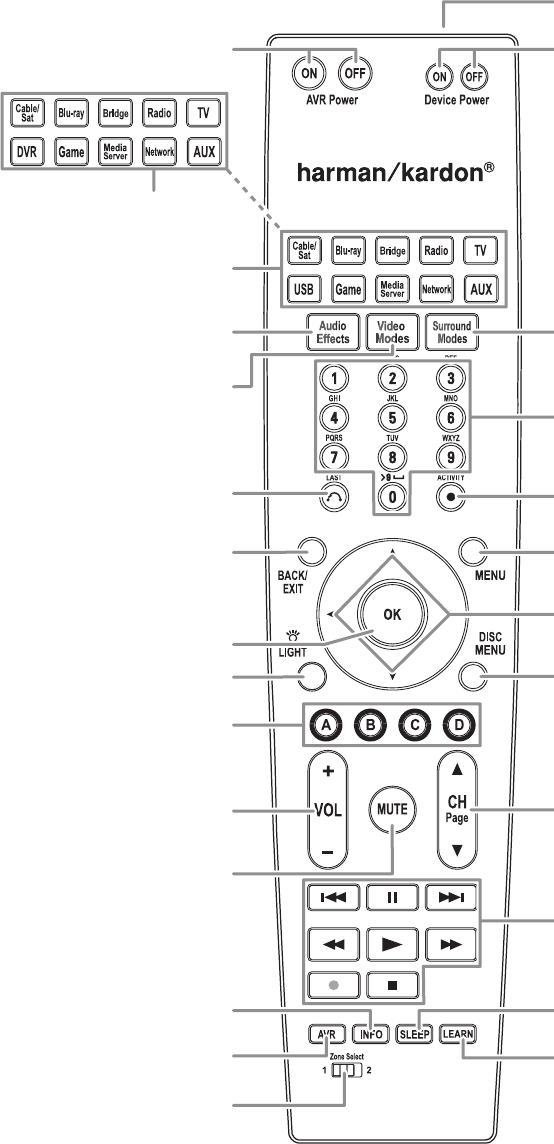
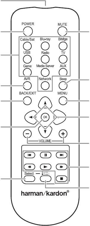
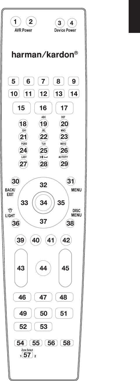
Refer to the numbered buttons when using the Function List in Table A13.
Remote Control Function List Reference
0295CSK - HK (x65Series) AVR3650_365_2650_265 CORE OM, WORK18 danny.indd 5301/07/11 11:34:14
AVR
5454
Appendix
Table A13 – Remote Control Function List
No.Button NameAVR
Radio
DVD
Media Server
TVThe BridgeFMAMXMDMC1000
01AVR Power OnAVR Power OnAVR Power OnAVR Power OnAVR Power OnAVR Power OnAVR Power OnAVR Power OnAVR Power On
02AVR Power OffAVR Power OffAVR Power OffAVR Power OffAVR Power OffAVR Power OffAVR Power OffAVR Power OffAVR Power Off
03Device Power OnPower OnOnPower OnPower On
04Device Power OffPower OffOffPower OffPower Off
05Cable/SatInput SelInput SelInput SelInput SelInput SelInput SelInput SelInput Sel
06Blu-rayInput SelInput SelInput SelInput SelInput SelInput SelInput SelInput Sel
07The BridgeInput SelInput SelInput SelInput SelInput SelInput SelInput SelInput Sel
08RadioRadioRadioRadioRadioRadioRadioRadioRadio
09TVInput SelInput SelInput SelInput SelInput SelInput SelInput SelInput Sel
10
USB (AVR 3650/AVR 365)
DVR (AVR 2650/AVR 265)
Input SelInput SelInput SelInput SelInput SelInput SelInput SelInput Sel
11GameInput SelInput SelInput SelInput SelInput SelInput SelInput SelInput Sel
12Media ServerInput SelInput SelInput SelInput SelInput SelInput SelInput SelInput Sel
13NetworkInput SelInput SelInput SelInput SelInput SelInput SelInput SelInput Sel
14AUXInput SelInput SelInput SelInput SelInput SelInput SelInput SelInput Sel
Libble takes abuse of its services very seriously. We're committed to dealing with such abuse according to the laws in your country of residence. When you submit a report, we'll investigate it and take the appropriate action. We'll get back to you only if we require additional details or have more information to share.
Product:
Forumrules
To achieve meaningful questions, we apply the following rules:
First, read the manual;
Check if your question has been asked previously;
Try to ask your question as clearly as possible;
Did you already try to solve the problem? Please mention this;
Is your problem solved by a visitor then let him/her know in this forum;
To give a response to a question or answer, do not use this form but click on the button 'reply to this question';
Your question will be posted here and emailed to our subscribers. Therefore, avoid filling in personal details.
Register
Register getting emails for Harman Kardon AVR 3650 at:
new questions and answers
new manuals
You will receive an email to register for one or both of the options.
Get your user manual by e-mail
Enter your email address to receive the manual of Harman Kardon AVR 3650 in the language / languages: English as an attachment in your email.
The manual is 4,43 mb in size.
You will receive the manual in your email within minutes. If you have not received an email, then probably have entered the wrong email address or your mailbox is too full. In addition, it may be that your ISP may have a maximum size for emails to receive.
If you have not received an email with the manual within fifteen minutes, it may be that you have a entered a wrong email address or that your ISP has set a maximum size to receive email that is smaller than the size of the manual.
The email address you have provided is not correct.
Please check the email address and correct it.
Your question is posted on this page
Would you like to receive an email when new answers and questions are posted? Please enter your email address.