modes in 32kHz, 44.1kHz, 48kHz or 96kHz, and 5.1 or 7.1 multichannel PCM. (Your
AVR will downmix the discrete surround back-channel information in 6.1-channel and
7.1-channel recordings into your system’s surround left and surround right channels.)
When the AVR receives a digital bitstream, it detects the encoding method and the
number of channels, which is displayed briefly as three numbers, separated by slashes
(e.g., “3/2/.1”).
The first number indicates the number of front channels in the signal: “1” represents
a monophonic recording (usually an older program that has been digitally remastered
or, more rarely, a modern program for which the director has chosen mono as a special
effect). “2” indicates the presence of the left and right channels but no center channel.
“3” indicates that all three front channels (left, right and center) are present.
The second number indicates whether any surround channels are present: “0” indicates
that no surround information is present. “1” indicates that a matrixed surround signal
is present. “2” indicates discrete surround left and right channels. (Bitstreams with
discrete surround back left and right channel signals will be indicated by a “4,” although
the AVR downmixes the surround back-channel information into the surround left and
right channels.)
The third number is used for the LFE channel: “0” indicates no LFE channel. “.1”
indicates that an LFE channel is present.
Dolby Digital 2.0 signals may include a Dolby Surround flag indicating DS-ON or DS-OFF,
depending on whether the 2-channel bitstream contains only stereo information or a
downmix of a multichannel program that can be decoded by the AVR’s Dolby Pro Logic
decoder. By default, these signals are played in Dolby Pro Logic II Movie mode.
When a PCM signal is received, the PCM message and the sampling rate (32kHz,
44.1kHz, 48kHz or 96kHz) will appear.
When only two channels – left and right – are present, the analog surround modes
may be used to decode the signal into multiple channels. If you would prefer a different
surround format than the native signal’s digital encoding, press the Surround Modes
button to display the Surround Modes menu (see
Selecting a Surround Mode,
on page
20).
The Auto Select option sets the surround mode to the native signal’s digital encoding,
e.g., Dolby Digital, DTS, Dolby TrueHD or DTS-HD Master Audio. For analog 2-channel
materials, the AVR defaults to the Logic 7 Movie mode. For Dolby Digital 2.0 programs,
the AVR defaults to the Dolby Pro Logic II Movie mode, which creates a 5.1-channel
surround-sound presentation from the 2-channel program. If you prefer a different
surround mode, select the surround-mode category: Virtual Surround, Stereo, Movie,
Music or Video Game. Press the OK button to change the mode.
Each surround-mode category is set to a default surround mode:
Virtual Surround: HARMAN virtual speaker. s
Stereo: 5-CH Stereo. s
Movie: Logic 7 Movie. s
Music: Logic 7 Music. s
Video Game: Logic 7 Game. s
You may select a different mode for each category. Below is a complete list of available
surround modes. (The actual surround modes available will depend on the number of
speakers in your system.)
Virtual Surround: HARMAN virtual speaker. s
Stereo: 2-CH Stereo or 5-CH Stereo. s
Movie: Logic 7 Movie, Dolby Pro Logic II Movie. s
Music: Logic 7 Music, Dolby Pro Logic II Music. s
Video Game: Logic 7 Game, Dolby Pro Logic II Game. s
Once you have programmed the surround mode for each type of audio, select the
line from the Surround Modes menu to override the AVR’s automatic surround-mode
selection.
The AVR will use the same surround mode the next time the source is selected
.
Please refer to
Table A9 in the Appendix for more information on which surround modes
are available with different bitstreams.
Dolby Pro Logic II Music Mode Adjustments
When you select Dolby Pro Logic II as the music surround mode, additional adjustments
become available:
* MODE : MUSIC *
DOLBY PLII MUSIC
CENTER WIDTH :3
DIMENSION :0
PANORAMA :Off
BACK TO MASTER MENU
Center Width: This setting affects how vocals sound through the three front speakers.
A lower number focuses the vocal information tightly on the center channel. Higher
numbers (up to 7) broaden the vocal soundstage. Use the Left/Right buttons to adjust
this setting.
Dimension: This setting affects the depth of the surround presentation, allowing you to
“move” the sound toward the front or rear of the room. The setting of “0” is a neutral
default. Setting “F-3” moves the sound toward the front of the room, while setting “R-3”
moves the sound toward the rear. Use the Left/Right buttons to adjust it.
Panorama: With the Panorama mode turned on, some of the sound from the front
speakers is moved to the surround speakers, creating an enveloping “wraparound”
effect. Each press of the OK button toggles the setting On or Off.
Manual Speaker Setup
Your AVR is flexible and may be configured to work with most speakers and to
compensate for the acoustic characteristics of your room.
The EzSet/EQ process automatically detects the capabilities of each connected speaker
and optimizes the AVR’s performance with your speakers. If you are unable to run EzSet/
EQ calibration, or if you wish to set up your AVR for your speakers manually, use the
Manual Speaker Setup on-screen menus.
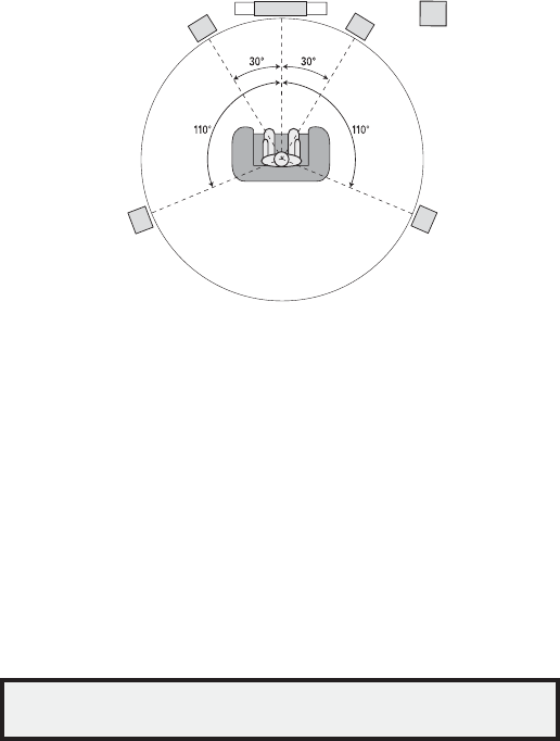
Before beginning, place your loudspeakers as explained in the
Place Your Speakers
section, on page 10, and connect them to the AVR. Consult the owner’s guide for the
speakers or the manufacturer’s Web site for their frequency-range specification. Although
you may set the AVR’s individual channel levels “by ear,” an SPL (sound-pressure level)
meter purchased at a local electronics store will provide greater accuracy.
Record your configuration settings in Tables A4 and A6 in the Appendix for easy re-entry
after a system reset or after the AVR’s Master Power switch has been turned off or the
unit has been unplugged for more than four weeks.
Step One – Determine Your Speakers’ Crossover Frequencies
Without using the EzSet/EQ process, the AVR can’t detect how many speakers
you’ve connected to it; nor can it determine their capabilities. Consult the technical
specifications for all of your speakers and locate the frequency response, usually given
as a range, e.g., 100Hz – 20kHz (±3dB). Write down the lowest frequency that each
of your speakers is capable of playing (100Hz in the above example) as the crossover
in Table A6 in the Appendix. NOTE: This frequency is
not
the same as the crossover
frequency listed in the speaker’s specifications.
For the subwoofer, write down the transducer size. The AVR’s bass management
determines which speakers will be used to play back the low-frequency (bass) portion
of the source program. Sending the lowest notes to small satellite speakers will result
in bad sound and may even damage the speakers. The highest notes may not be heard
at all through the subwoofer.
With proper bass management, the AVR divides the source signal at a crossover point.
All information above that crossover point is played through your system’s speakers,
and all information below the crossover point is played through the subwoofer. This way,
each loudspeaker in your system will perform at its best, delivering a more powerful and
enjoyable sound experience.
22
AVR 1650/AVR 165Advanced Functions, continued
Step Two – Measure the Speaker Distances
Ideally, all of your speakers would be placed in a circle, with the listening position at the
center. However, you may have had to place some speakers a little farther away from the
listening position than others. Sounds that are supposed to arrive simultaneously from
different speakers may blur, due to different arrival times.
Your AVR provides a Distance adjustment that compensates for these real-world
speaker-placement differences.
Measure the distance from each speaker to the listening position, and write it down
in Table A4 in the Appendix. Even if all of your speakers are the same distance from
the listening position, enter your speaker distances as described in
Set the Speaker
Distances,
on this page.
Step Three – Manual Setup Menu
Now you are ready to program the AVR. Sit in your usual listening position, and make the
room as quiet as possible.
With the AVR and video display turned on, press the OSD button to display the menu
system and select Manual Setup. The Manual Setup menu will appear:
* MANUAL SETUP *
NUMBER OF SPEAKERS
SUB MODE : SUB
CROSSOVER
DISTANCE
LEVEL ADJUST
BACK TO MASTER MENU
NOTE: All of the speaker setup submenus include a “Back to…” option. To save the
current settings, select the Back to… option.
For best results, adjust the submenus in this order: Number of Speakers, Crossover, Sub
Mode, Distance and Level Adjust.
Number of Speakers
This selection lets you program the correct setting for each speaker group. The settings
in this menu affect the remainder of the speaker-setup process and the availability of
various surround modes at any time.
Select ON when the speakers are present in the system; select OFF for positions where
no speakers are installed. The Front Left & Right setting is always ON and may not be
disabled.
* NUMBER OF SPEAKERS *
LEFT/RIGHT : ON
CENTER : ON
SURROUND : ON
SUBWOOFER : ON
BACK TO MANUAL SETUP
When you have finished, select Back to Manual Setup.
Crossover (Size)
After you return to the Manual Setup menu, navigate to the Crossover line and press the
OK button to display the Crossover menu.
* CROSSOVER *
LEFT/RIGHT : 100Hz
CENTER : 100Hz
SURROUND : 100Hz
SUBWOOFER : 10inch
BACK TO MANUAL SETUP
Refer to Table A6 for each speaker’s crossover frequency.
NOTE: The AVR will let you adjust settings only for those speaker groups you set to On in
the Number of Speakers menu.
For each speaker group, select one of these eight crossover frequencies: LARGE, 40Hz,
60Hz, 80Hz, 100Hz, 120Hz, 150Hz or 200Hz. If the speaker’s crossover frequency is
below 40Hz, select the first option, LARGE. This setting doesn’t refer to the speaker’s
physical size but to its frequency response, which is also called “full range.”
Specify the size of the subwoofer’s transducer as 8, 10, 12 or 15 inches. The AVR always
sets the subwoofer crossover to 100Hz but uses the transducer size for equalization.
Write down the settings in Table A6 in the Appendix.
When you have finished entering the settings, select Back To Manual Setup.
Sub Mode
After you return to the Manual Setup menu, navigate to the Sub Mode line and press
the OK button to display the Sub Mode menu. This setting depends upon the Crossover
setting you selected for the front left and right speakers.
If you set the front speakers to a numeric crossover frequency, the subwoofer setting s
will always be SUB. All low-frequency information will always be sent to the subwoofer.
If you don’t have a subwoofer, either upgrade to full-range front left and right speakers
or add a subwoofer at the earliest opportunity.
If you set the front speakers to LARGE, select one of the three following settings for s
the subwoofer:
L/R+LFE: This setting sends all low-frequency information to the subwoofer, including
a) information that would normally be played through the front left and right speakers
and b) the special low-frequency effects (LFE) channel information.
OFF: Select this setting when no subwoofer is in use. All low-frequency information
will be sent to the front left and right speakers.
LFE: This setting plays low-frequency information contained in the left and right
program channels through the front left and right speakers, and directs only the LFE-
channel information to the subwoofer.
When you have finished entering the settings, select Back To Manual Setup.
Set the Speaker Distances
As described above in Step Two, when you measured the distances from each of your
speakers to the listening position, your AVR provides an adjustment that compensates
for the different distances so that the sound from each speaker will reach the listening
position at the proper time. This process will improve the clarity and detail of the
sound.
After you return to the Manual Setup menu, navigate to the Distance line and press the
OK button to display the Distance menu.
* DISTANCE *
FL : 10FT
CEN : 10FT
FR : 10FT
SR : 10FT
SL : 10FT
SUB : 10FT
DELAY RESET : OFF
UNIT : FEET
A/V SYNC DELAY : 0mS
BACK TO MANUAL SETUP
Enter the distance from each speaker to the listening position that you measured in Step
Two and recorded in Table A4 in the Appendix (see page 28). Select a speaker, then use
the Left/Right buttons to change the measurement. You can enter distances between 0
and 30 feet (9.1m). The default distance for all speakers is 10 feet (3m).
The default unit of measurement is feet. To change the unit to meters, scroll down to the
Unit line and press the Left/Right buttons.
When you have finished entering the settings, select Back To Manual Setup.
23
AVR 1650/AVR 165
ENGLISH
Advanced Functions, continued
Step Four – Setting Channel Output Levels Manually
For a conventional stereo AVR, a simple balance control adjusts the stereo imaging by
varying the relative loudness of the left and right channels. In a home theater system
with up to seven main channels plus a subwoofer, achieving proper imaging becomes
both more critical and more complex. The goal is to ensure that each channel is heard
at the listening position with equal loudness (when signals of equal loudness are played
through them).
Your AVR’s EzSet/EQ calibration can handle this critical task for you simply and
automatically. However, the AVR’s Adjust Speaker Levels menu allows you to calibrate
the levels manually, either using the system’s built-in test tone or while playing source
material.
After you return to the Manual Setup menu, navigate to the Level Adjust line and press
the OK button to display the Level Adjust menu.
* LEVEL ADJUST*
FL : 0dB
CEN: 0dB
FR : 0dB
SR : 0dB
SL : 0dB
SUB: 0dB
CHANNEL RESET: OFF
TEST TONE SEQ: MANUAL
TEST TONE : OFF
BACK TO MANUAL SETUP
All of the system’s speakers will appear with their current level settings. You can adjust
each speaker’s level between –10dB and +10dB in 1dB increments.
While making adjustments, you can measure the channel levels in one of these ways:
Preferably, use a handheld SPL meter set to the C-weighting, slow scale. Adjust each s
speaker so that the meter reads 75dB when the AVR’s built-in test noise is playing.
By ear. Adjust the levels so that the test tone sounds equally loud to you when it plays s
through each speaker.
To set your levels using the AVR’s internal test tone, select the menu’s Test Tone Seq
line and use the Left/Right buttons to select between Auto and Manual. After selecting
Auto or Manual, move the cursor to the Test Tone line and use the Left/Right buttons to
change the setting to On.
Auto: The test tone will automatically circulate to all speakers, as indicated by the
highlight bar. Use the Left/Right buttons to adjust the level for any speaker when the
test tone is paused there. Use the Up/Down buttons to move the cursor to another line,
and the test tone will follow the cursor. To stop the test tone, use the Up/Down buttons
to move the cursor out of the screen’s speaker-listings area.
Manual: The test tone will stay on the current speaker until you use the Up/Down
buttons to move it to another speaker. Use the Left/Right buttons to adjust the level for
the speaker through which the test tone is playing.
If you are using an external source to set your output levels, set Test Tone to Off, use the
Up/Down buttons to navigate to each speaker, and use the Left/Right buttons to adjust
the speaker’s level while the source plays. NOTE: If you are using a handheld SPL meter
with external source material, such as a test disc or an audio selection, play it and
adjust the AVR’s master volume control until the meter measures 75dB. Then adjust the
individual speaker levels.
Channel Reset: To reset all channel levels to their factory defaults of 0dB, select this line
and press the Left/Right buttons.
When you have finished adjusting the speaker levels, record the settings in Table A6 in
the Appendix. Then select the Back to Manual Setup option in the OSD.
Notes on Setting Speaker Volumes in Home Theater Systems:
While setting your system’s individual speaker volume levels is ultimately up to your
personal taste, here are some ideas you may find helpful:
For films and video-music programs, your overall goal should be to create an s
enveloping, realistic sound field that draws you into the film or music program without
drawing your attention away from the action on the screen.
For multichannel music recordings, some music producers will create a sound field s
that places the musicians all around you; others will create a sound field that places
the musicians in front of you, with more subtle ambience in the surround speakers (as
you would experience in a concert hall).
In most 5.1-channel film soundtracks, the surround speakers are not intended to be s
as loud or as active as the front speakers. Adjusting the surround speakers so they are
always as loud as the front speakers could make dialogue difficult to understand and
will make some sound effects sound unrealistically loud.
Notes on Setting Subwoofer Volume:
Sometimes the ideal subwoofer volume setting for music is too loud for films, while s
the ideal setting for films is too quiet for music. When setting the subwoofer volume,
listen to both music and films with strong bass content and find a “middle ground”
volume level that works for both.
If your subwoofer always seems too loud or too quiet, you may want to place it in a s
different location. Placing the subwoofer in a corner will always tend to increase its
bass output, while placing it away from any walls or corners will always tend to lessen
its bass output.
System Setup
The AVR’s System Setup menu lets you customize in what way many of the AVR’s
features operate. Press the OSD button and navigate to the System Setup line. Press the
OK button to display the System Setup menu.
VFD Fade Time Out: Some people find the brightness of the AVR’s front-panel display
distracting during movies or listening sessions. It’s possible to dim the front-panel
display completely using the remote’s Display Dimmer button (see
System Remote
Control Functions,
on pages 8 and 9). The VFD Fade Time Out sets the display to remain
dark most of the time, lighting up only when a button is pressed or a remote command
is received, and going dark again five seconds after the last command. The feature also
causes the display to light up only when a button is pressed but the display immediately
begins to fade to dark. This setting allows you to program the length of the fade time.
Select a time-out period of between three and ten seconds, or select Off if you prefer to
leave the displays on at all times or to use the Display Dimmer button.
Volume Default and Default Volume Set: These two settings are used together to
program the volume level when you turn on the AVR. Set Volume Default to On, and then
set the Default Volume Set to the desired turn-on volume. When Volume Default is set
to Off, the AVR will turn on at the last-used volume setting from the previous listening
session.
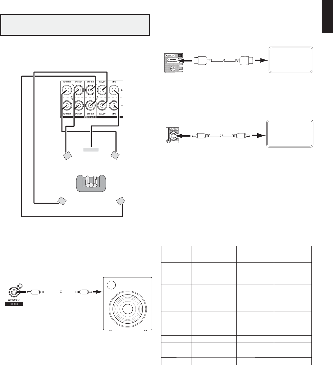
HDMI Audio To TV: This setting determines whether HDMI audio signals are passed
through the HDMI Monitor Out connector to the video display. In normal operation, leave
this setting at Off, as audio will be played through the AVR. To use the TV by itself, without
the home theater system, turn this setting to On. In this case, you will need to mute the
TV’s speakers (or switch the setting to Off) when using the AVR for audio.
Semi OSD Time Out: Program the amount of time (2 to 5 seconds) the two-line semi-
OSD status messages remain on screen, or deactivate the semi-OSD display altogether
if you find it distracting. These messages will continue to appear on the front panel of
the AVR.
Full OSD Time Out: Program the amount of time (20, 30, 40 or 50 seconds) the full OSD
menus remain visible on screen. The full OSD system may not be deactivated. NOTE: It
isn’t possible to view video sources while the full OSD menus are displayed.
HDMI Link: This setting allows the communication of control information among the
HDMI devices in your system. Turn this setting to On to allow control communication
among the HDMI devices; turn the setting to Off to forbid control communication.
HDMI ARC: Selecting On will send audio from the TV to the AVR via the HDMI Audio
Return Channel (ARC) connection (which is in the HDMI cable connecting the AVR to the
TV). This way, whenever you’re watching a source that is connected directly to your TV
(such as an Internet connection), you can listen to the sound through the AVR. NOTE: This
setting is available only when HDMI Link is set to On.
24
AVR 1650/AVR 165Advanced Functions, continued
Advanced Remote Control Programming
Remote Channel-Control Punch-Through
The punch-through feature allows you to operate one component while setting certain
groups of controls to operate another component. For example, while using the AVR
controls for surround modes and other audio functions, you may also use the remote
to operate the transport controls of your Blu-ray Disc player. Or while using the remote
to control video functions on your TV, you may also use the remote to change channels
on your cable box.
To program punch-through control while operating any device:
For three seconds, press and hold the Source Selector button (or the AVR button) for 1.
the main device the remote will be operating. The Program Indicator LED will flash,
indicating that the remote is in Program mode and that you may release the button.
Select the type of punch-through programming.2.
To program volume-control punch-through, press the Volume Up button.a)
To program channel-control punch-through, press the Volume Down button.b)
To program transport-control punch-through, press the Play transport-control button.c)
Press the Source Selector button for the device whose volume, channel or transport-3.
controls you will use while operating the device selected in the first step. The Program
Indicator LED will flash to confirm.
To undo punch-through programming, follow the same steps as above, but press the
same Source Selector button in Steps 1 and 3.
You may reassign the transport-control punch-through programming for the AVR, VID2
and VID3 devices to another device, such as a CD player. If you wish to remove transport-
control punch-through altogether for the AVR, VID2 or VID3 device, follow the same
procedure as for programming punch-through, but in Step 3 press either of the other
two of these three special selector buttons. For example, to remove transport-control
punch-through from the VID3 device so that pressing any of the transport controls will
have no effect, press and hold the VID3 Button until the Program Indicator LED flashes,
then press the Play Button, followed by either the AVR or VID2 Button.
Programming Macro Commands
Each of the AVR remote’s four Macro buttons and the Power On button (see
System
Remote Control Functions,
on pages 8 and 9) can be programmed to send out up to
19 commands at one time from a single button push. Any AVR remote control button’s
function from any mode (except the Mute button, the Dim button and the Channel Up/
Down buttons) can be programmed into a macro.
NOTE: Use caution when programming complicated macros. It isn’t possible to program
a pause or delay before sending additional commands after a “Power On” command,
and the component may not be ready to respond to commands immediately after
powering on.
To program a macro:
Simultaneously press one of the four Macro buttons, or the Power On button, and the 1.
Mute button to enter the Programming mode.
Press in up to 19 commands that you want stored in that Macro button. Press the Source 2.
Selector button for each device (or AVR button for the AVR itself) before you enter
individual commands. This step counts as one of the 19 commands allowed for each
Macro.
For the Power On command, DO NOT press the Power On button. Press the Mute button 3.
instead.
Press the Power Off button to program the Power Off command.4.
Press the Sleep button to end the programming process. 5.
It isn’t possible to “edit” a command within a macro. However, you may erase the macro
as follows:
Simultaneously press and hold the Mute button and the Macro button containing the 1.
macro until the Program Indicator LED flashes.
Press the Channel Down button to erase the macro.2.
To execute a macro, press the Macro button (or the Power On button) into which you
programmed the macro.
Recording
Two-channel analog and digital audio signals, as well as composite video signals, are
normally available at the appropriate recording output connectors. To make a recording,
connect your audio or video recorder to the appropriate AVR output connectors as
described in the
Making Connections
section, insert blank media in the recorder and
make sure the recorder is turned on and recording while the source is playing. Refer to
the recording device’s instructions for complete information about making recordings.
NOTES:
The AVR does not convert analog signals to digital or vice versa.1.
Only PCM digital audio signals are available for recording. Proprietary formats such as 2.
the Dolby Digital and DTS bitstreams may not be recorded using the digital audio
connections. Use the analog audio connections to make an analog recording.
HDMI and component video sources are not available for recording.3.
Please make certain that you are aware of any copyright restrictions on any material you 4.
record. Unauthorized duplication of copyrighted materials is prohibited by law.
Sleep Timer
The sleep timer sets the AVR to play for up to 90 minutes and then turn off automatically.
Press the Sleep button on the remote, and the time until turn-off will be displayed on the
front-panel Message display and on a connected TV. Each additional press of the Sleep
button decreases the play time by 10 minutes, with a maximum of 90 minutes. The
SLEEP OFF setting disables the sleep timer.
When the sleep timer has been set, the front-panel display will automatically dim to
half brightness.
If you press the Sleep button after the timer has been set, the remaining play time will
be displayed. Press the Sleep button again to change the play time.
Resetting the Remote
To reset the remote to its factory-default condition, simultaneously press and hold any
Source Selector button and the “0” Number button. When the Program Indicator LED
flashes amber, enter the code “333.” When the green LED goes out, the remote control
will be reset.
Processor Reset
If the AVR behaves erratically after a power surge, first turn off the rear-panel Main
Power switch and unplug the AC power cord for at least 3 minutes. Plug the cord back
in and turn the AVR on. If this procedure doesn’t help, reset the AVR’s processor as
described below.
NOTE: A processor reset erases all user configurations, including video resolution,
speaker and level settings, and tuner presets. After a reset, reenter all of these settings
from your notes in the Appendix worksheets.
To reset the AVR’s processor:
Press the front-panel Standby/On switch to place the unit in the Standby mode (the 1.
Power Indicator LED will turn amber).
Press and hold the front-panel Surround Mode button for at least 5 seconds until the 2.
RESET message appears on the front-panel Message display.
If the AVR does not function correctly after a processor reset, contact an authorized
Harman Kardon service center for assistance. Authorized service centers may be located
by visiting our Web site at www.harmankardon.com.
Memory
If the AVR is unplugged or experiences a power outage, it will retain your user settings
for up to four weeks.
25
AVR 1650/AVR 165
ENGLISH
Troubleshooting
Symptom
CauseSolution
Unit does not function when Main Power switch is
turned on
No AC powersEnsure that the power cord is plugged into a live AC s
power outlet
Check if the AC outlet is switch-controlled s
Front-panel Message display lights, but there's no
sound or picture
Intermittent input connection s
Mute is on s
Volume control is turned down s
Secure all input and speaker connections s
Press Mute button s
Turn up Volume control s
No sound from any speaker; PROTECT message
appears on Message display
Amplifier is in protection mode due to possible short s
circuit
Amplifier is in protection mode due to internal problems s
Check all speaker wires at speaker and AVR s
connections for crossed wires
Contact your local Harman Kardon service center s
No sound from center or surround speakersIncorrect surround mode s
Program material is monophonic s
Incorrect speaker configuration s
Program material is stereo s
Select a surround mode other than stereo s
Mono programs contain no surround information s
Check the speaker configuration in the setup menu s
The surround decoder may not create center- or s
surround-channel information from nonencoded stereo
programs
Unit does not respond to remote control commandsWeak batteries in remote s
AVR not selected s
Remote sensor is obscured s
Change batteries in remote s
Press the Setup/AVR button s
Ensure that the AVR’s front-panel remote sensor is in s
the line of sight of the remote
Intermittent buzzing in tunerLocal interference sMove the AVR or antenna away from computers, s
fluorescent lights, motors or other electrical appliances
Unable to activate remote control Programming modeSource Selector button is not held for at least 3 seconds sBe sure to hold the Source Selector button for at least s
3 seconds
Additional information on troubleshooting possible problems with your AVR and installation-related issues may be found in the list of “Frequently Asked Questions,” which is located in the Product
Support section of our Web site: www.harmankardon.com
Troubleshooting
26
AVR 1650/AVR 165Specifications
Specifications
Audio Section
Stereo power:95W per channel, two
channels driven @ 8 ohms,
20Hz – 20kHz, <0,07%
THD
Multichannel power:95W per channel, two
channels driven @ 8 ohms,
20Hz – 20kHz, <0,07%
THD
Input sensitivity/impedance:200mV/47k ohms
Signal-to-noise ratio (IHF-A):100dB
Surround system adjacent-channel separation:Dolby Pro Logic/PLII: 40dB
Dolby Digital: 55dB
DTS: 55dB
Frequency response:10Hz – 130kHz
(+0dB/–3dB)
High instantaneous-current capability (HCC): ±25 amps
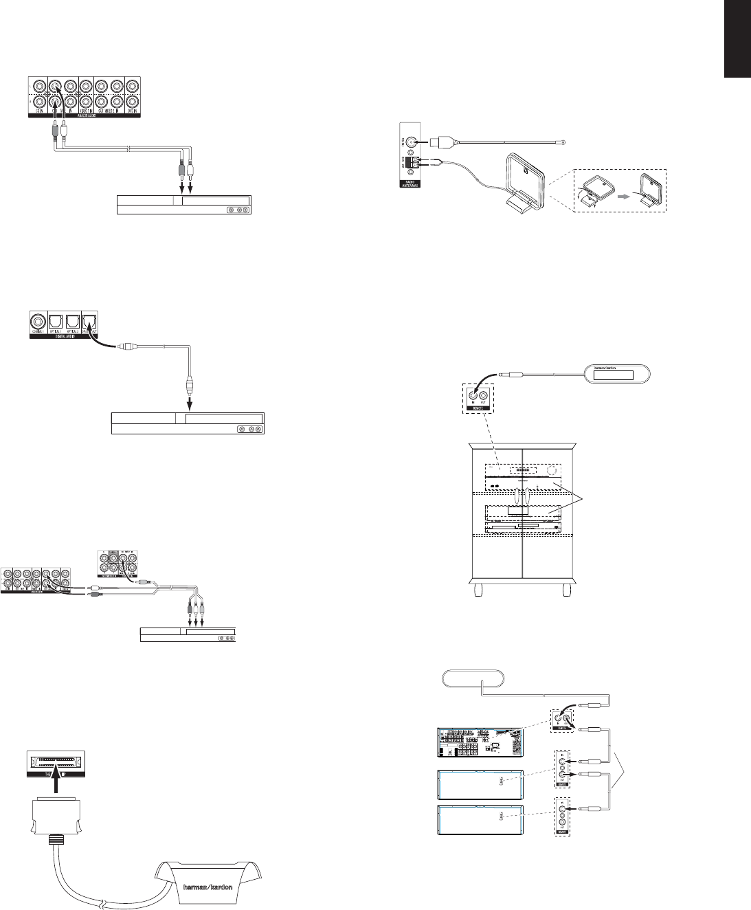
VCR, DVR, PVR, or other audio/video recorderVideo 2Video 2 Analog (inputs and outputs) s
Any one available coaxial or optical digital audio s
input with corresponding coax digital output
Composite Video 2 Input s
For recording, use Composite Video 2 Output s
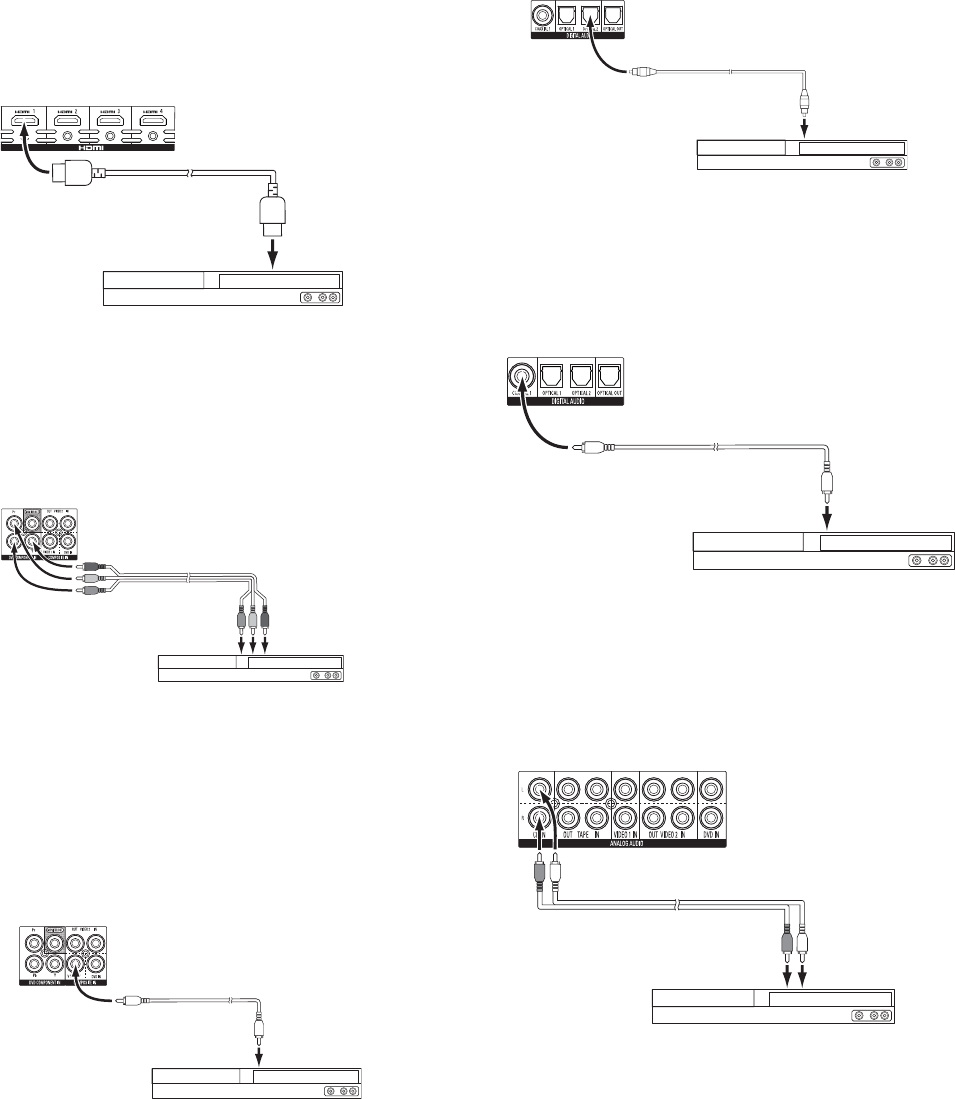
DVD player, Blu-ray Disc playerDVD or HDMI (for
Blu-ray Disc)
DVD Analog Inputss
Coax 1 Input s
DVD Component Video Input s
HDMI-capable disc player, game console or
other audio/video device
HDMI 1HDMI 1 Input sHDMI 1 Input s
HDMI-capable disc player, game console or
other audio/video device
HDMI 2HDMI 2 Input sHDMI 2 Input s
HDMI-capable disc player, game console or
other audio/video device
HDMI 3HDMI 3 Input sHDMI 3 Input s
HDMI-capable disc player, game console or
other audio/video device
HDMI 4HDMI 4 Input sHDMI 4 Input s
Portable audio deviceAUXAUX Input on front panel sNot required s
CD playerCDCD Analog Inputs s
Any one available coaxial or optical digital audio s
input
Not required s
CD-R, MiniDisc, cassetteTapeTape Analog (inputs and outputs) s
Any one available coaxial or optical digital audio s
input
Use corresponding optical digital output s
Not required s
iPod or iPhoneBridgeThe Bridge IIIP sNot required s
Note: The AVR is equipped with a total of three digital audio inputs. Certain digital audio connections are recommended simply because those digital audio inputs are assigned to those sources by
default at the factory. But any digital audio input may be reassigned to any source. Since you may not be using all of the AVR's sources, you may reassign a digital audio input that is recommended
for a source you aren’t using to another device. Table A1 is a guideline; you may need to make adjustments to fit your system.
Note: When any of the transport controls are pressed while the remote is in AVR or Video 2 mode, the remote will automatically switch to DVD mode, and the command will be applied
to the DVD player. If you then press a button native to the original mode, e.g., Volume Down for the AVR, the remote will revert to the original mode. See
Libble takes abuse of its services very seriously. We're committed to dealing with such abuse according to the laws in your country of residence. When you submit a report, we'll investigate it and take the appropriate action. We'll get back to you only if we require additional details or have more information to share.
Product:
Forumrules
To achieve meaningful questions, we apply the following rules:
First, read the manual;
Check if your question has been asked previously;
Try to ask your question as clearly as possible;
Did you already try to solve the problem? Please mention this;
Is your problem solved by a visitor then let him/her know in this forum;
To give a response to a question or answer, do not use this form but click on the button 'reply to this question';
Your question will be posted here and emailed to our subscribers. Therefore, avoid filling in personal details.
Register
Register getting emails for Harman Kardon AVR 1650 at:
new questions and answers
new manuals
You will receive an email to register for one or both of the options.
Get your user manual by e-mail
Enter your email address to receive the manual of Harman Kardon AVR 1650 in the language / languages: English as an attachment in your email.
The manual is 1,84 mb in size.
You will receive the manual in your email within minutes. If you have not received an email, then probably have entered the wrong email address or your mailbox is too full. In addition, it may be that your ISP may have a maximum size for emails to receive.
If you have not received an email with the manual within fifteen minutes, it may be that you have a entered a wrong email address or that your ISP has set a maximum size to receive email that is smaller than the size of the manual.
The email address you have provided is not correct.
Please check the email address and correct it.
Your question is posted on this page
Would you like to receive an email when new answers and questions are posted? Please enter your email address.