*#1 $OM%OM$2OM Owner’s Manual
T
IMPORT ............................................ 2
IMPORT 4
BA ......................................................................... 5
Index .............................................................................................. 8
MAIN FEA ............................................................................ 9
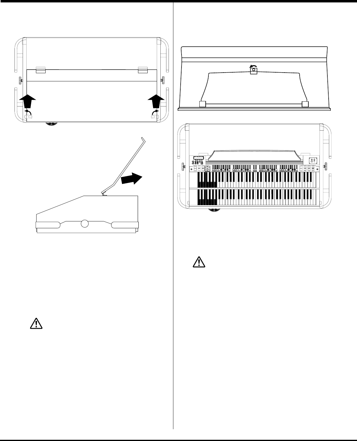
HOW TO ASSEMBLE (B-3 mk2) ................................................... 1
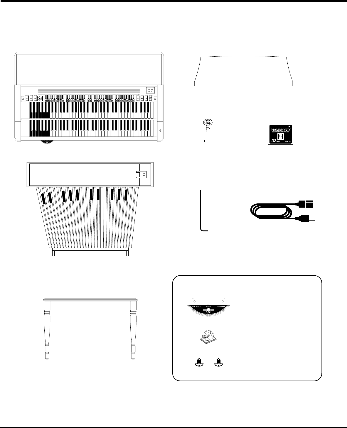
Components ....................................................................................... 10
Connect the P ...................................................................... 11
Attach the Leslie Speed Switch (USA only) ....................................... 11
Attach the MAIN/ECHO Switch (optional) ............................................ 12
Bench ................................................................................................. 12
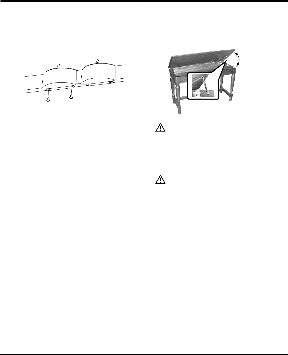
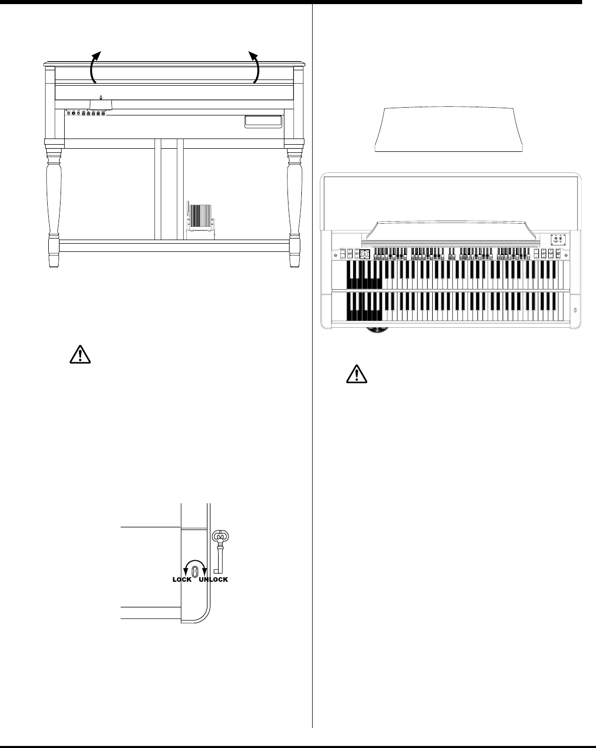
Manual Lid .......................................................................................... 13
Put on the Music Rack ........................................................................ 13
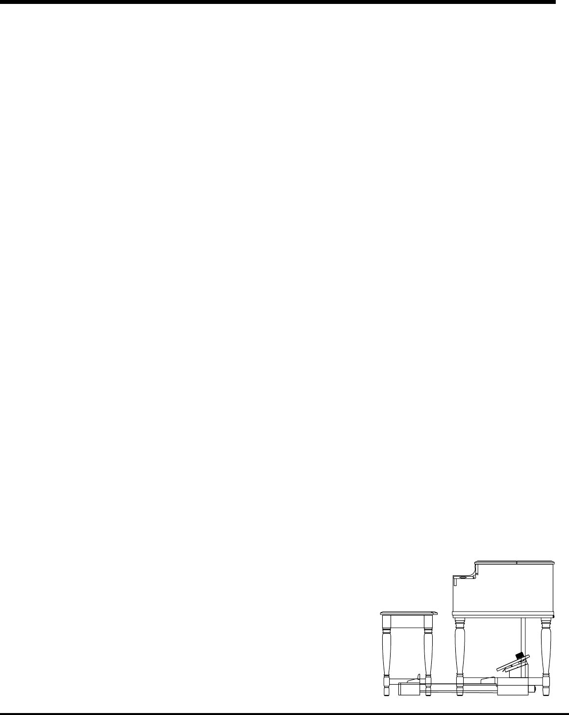
HOW TO ASSEMBLE (B-3P mk2) ................................................. 14
Components ....................................................................................... 14
Mount the Organ on the Stand ............................................................ 15
Connect the Expression Pedal............................................................. 16
Connect the P ...................................................... 16
Attach the Leslie Speed Switch ........................................................... 17
Attach the MAIN/ECHO Switch (optional) ............................................ 17
Open the Manual Lid ........................................................................... 18
Install the Music Rack......................................................................... 18
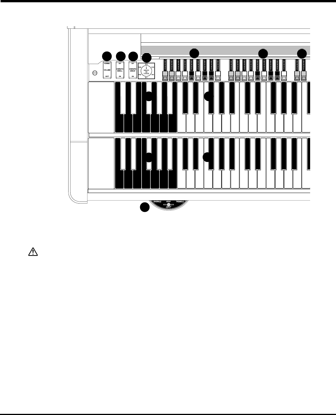
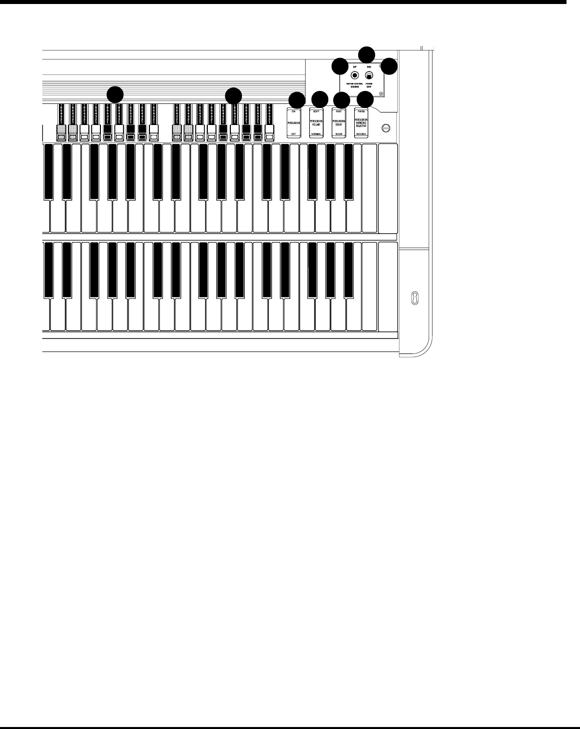
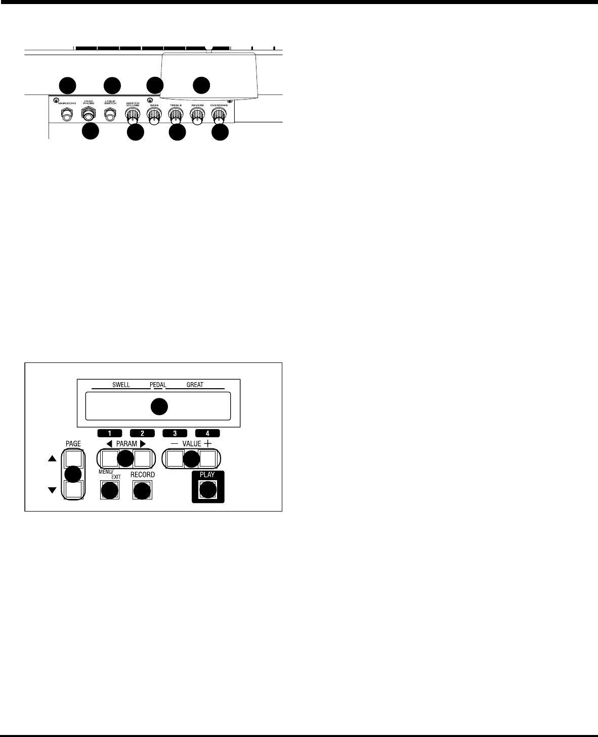
NAMES AND FUNCTIONS ............................................................. 2
T ........................................................................ 2
V ...................................................................................... 22
Control P ...................................................................................... 2
Power P ....................................................... 23
Accessor................................................ 23
Accessory Panel (B-3P mk2).............................................................. 24
Power P .................................................................... 24
PEDALS .............................................................................................. 25
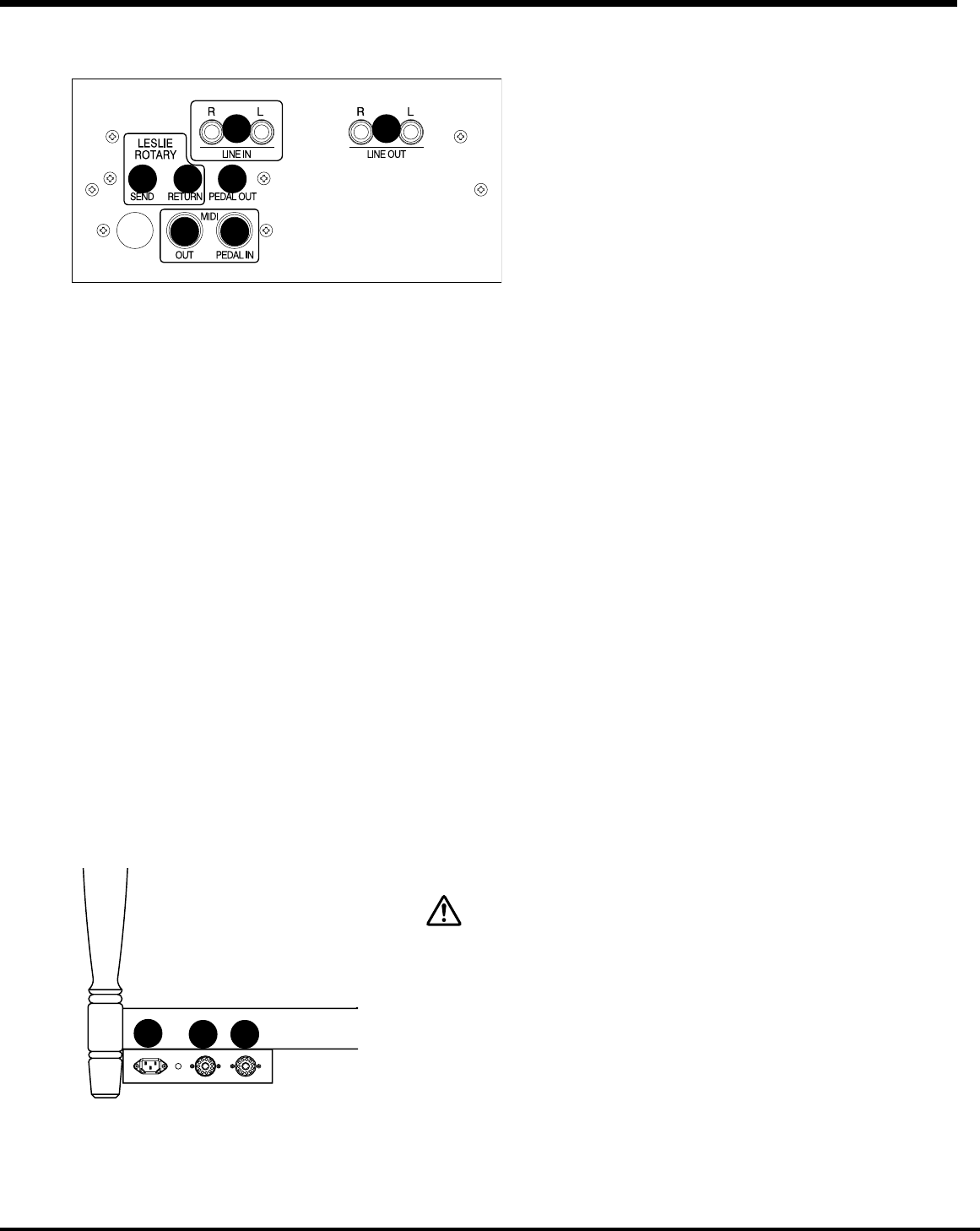
HOOK 27
BASIC HOOK-UP ........................................................................... 28
B-3 mk2, C ...................................................................................... 2
B-3P mk2 .................................................................................................... 2
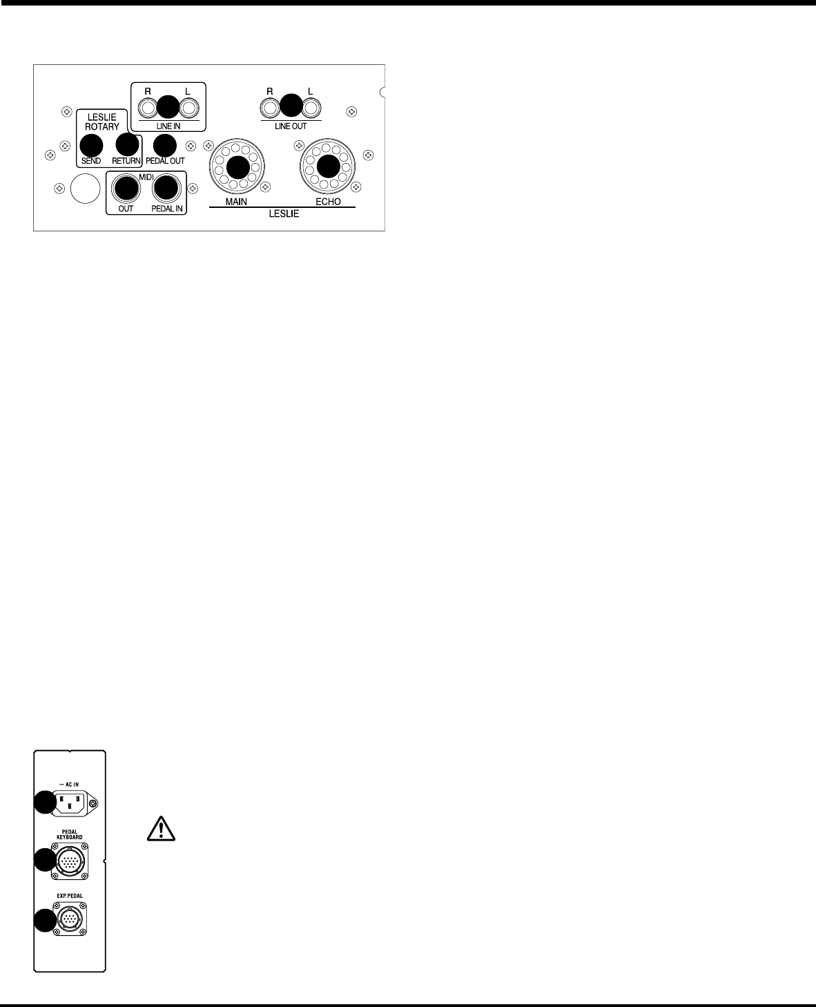
USING EFFECT L ................................................................... 30
USING A MIDI SOUND MODULE .................................................. 30
USING TWO LESLIE SPEAKERS ................................................... 31
REINFORCING THE BASS ............................................................. 31
USING NO LESLIE SPEAKER ........................................................ 32
USING HEADPHONES ................................................................... 32
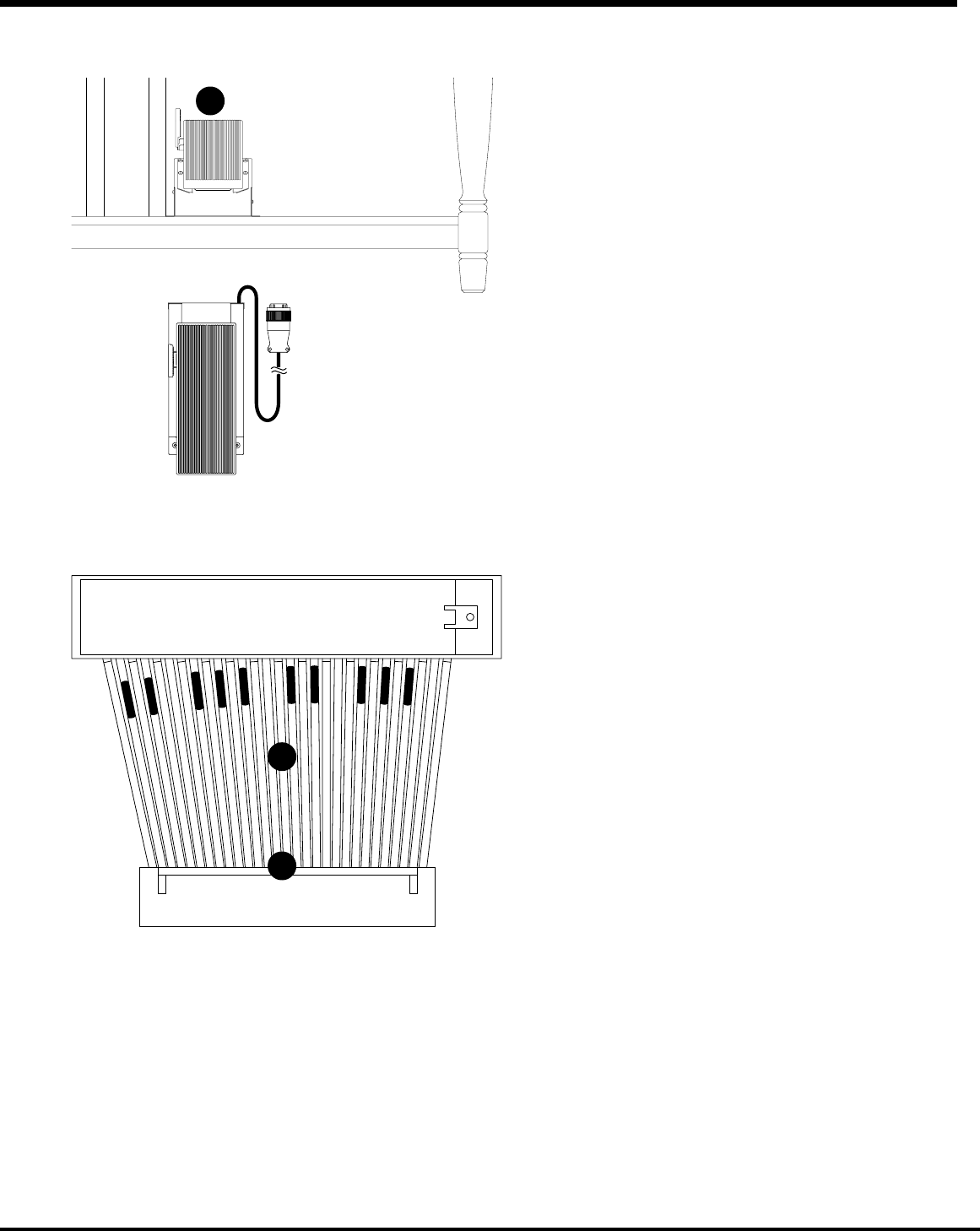
CONNECTING THE MIDI PEDALBOARD ........................................ 33
TURN ON AND PLA 35
POWER ON ................................................................................... 36
How to power on ................................................................................ 36
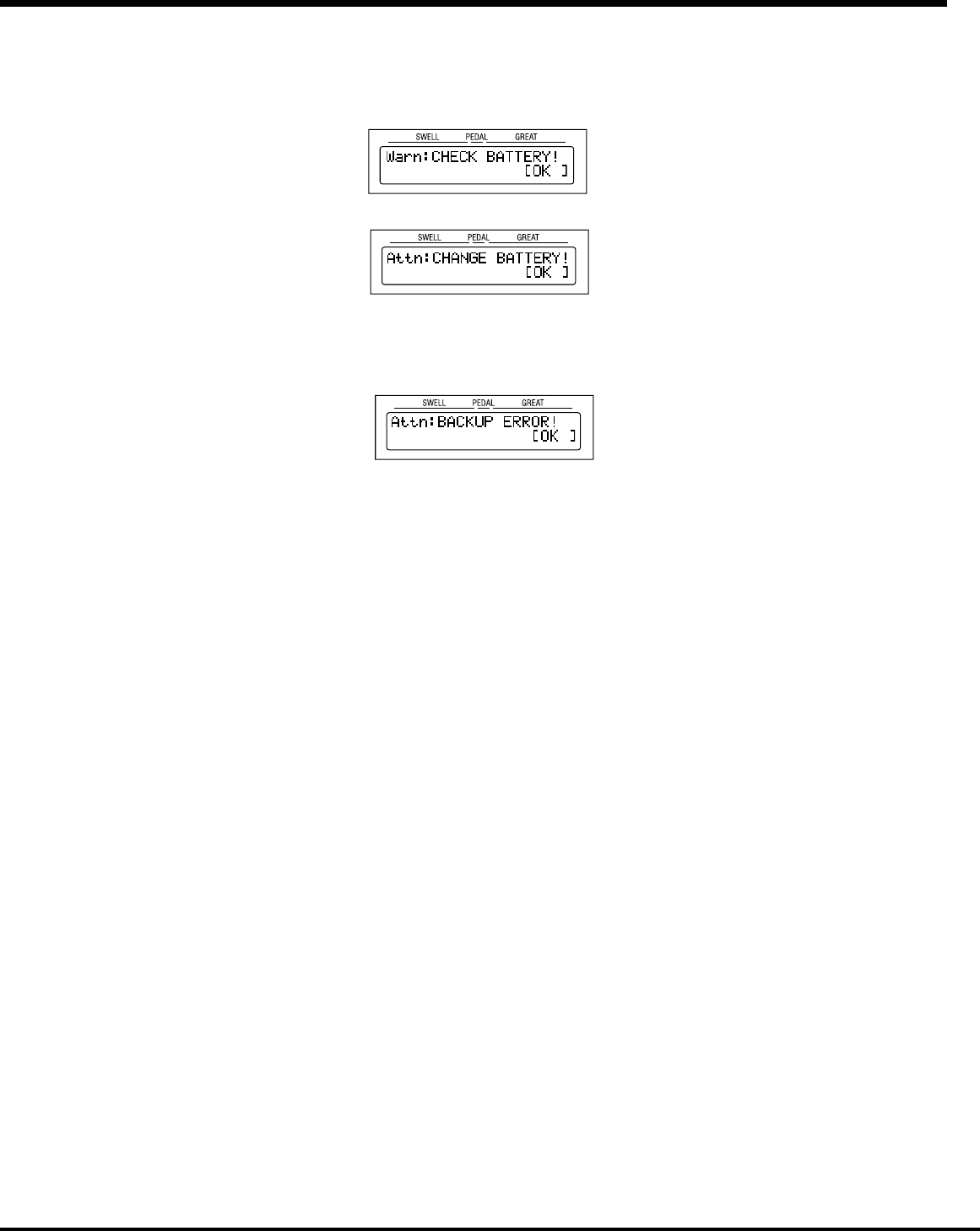
Back-Up .............................................................................................. 36
Reset to the initial status ..................................................................... 36
USE OF PRESET KEYS
How to call the Preset ......................................................................... 37
Ex. Select “2-G” .......................................................................................... 3
Play the P............................................................................ 38
ADDING EXPRESSION TO Y
Expression Pedal ................................................................................ 39
Foot Switch ......................................................................................... 39
Motor Control Switch .......................................................................... 39
TRY MAKING Y ................................................ 4
Select the Preset Key [B] .................................................................... 40
Pull out the B Drawbars ...................................................................... 40
Add Percussion .................................................................................. 4
Add Effects ......................................................................................... 41
VIBRA ...............................................................................
OVERDRIVE ................................................................................................. 4
LESLIE .........................................................................................................
REVERB .......................................................................................................
EQUALIZER ..................................................................................................
PEDAL SUST ................................................................................. 42
MANUAL BASS ................................................................................... 42
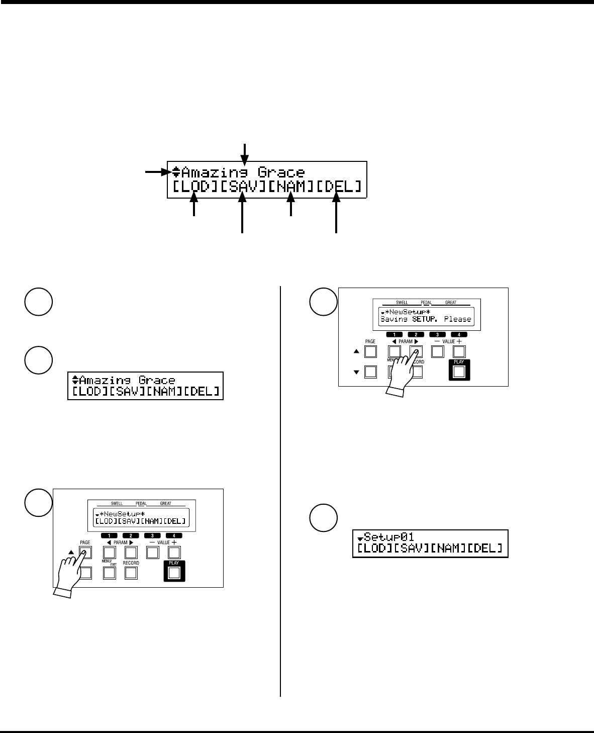
Recording P ........................................................................ 43
Ex. Memorize to “2-D” . 43
SET ............................................ 45
SOUND ENGINE STRUCTURE ....................................................... 46
System str........................................................... 4
HARMONIC DRAWBARS™ ........................................................... 48
Drawbars for the Swell/Great Manuals ................................................ 49
Relation between the Preset K ................................... 49
WHITE DRAWBARS ..................................................................................... 49
BLACK DRAWBARS .....................................................................................
BROWN DRAWBARS ................................................................................... 4
Drawbars for the P .............................................................. 4
Drawbar Registration P ............................................................ 5
Modern Drawbar Registrations ........................................................... 51
Controlling the Registration while playing a P .............................. 5
PERCUSSION
Notes .................................................................................................. 53
“Percussion does not sound!” ..................................................................... 53
DRAWBAR CANCEL ..................................................................................... 5
SINGLE TRIGGER ........................................................................................ 53
VIBRA ................................................................ 54
OVERDRIVE .................................................................................. 55
LESLIE .......................................................................................... 56
EQUALIZER ................................................................... 57
Equalizer ............................................................................................. 57
Reverb ................................................................................................ 57
PRESETS ...................................................................................... 5
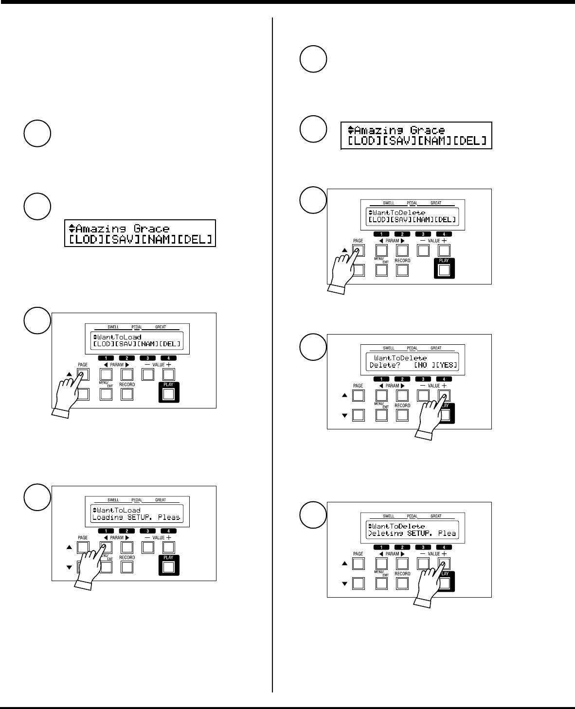
BANK and KEY .................................................................................... 58
Using Plural Presets at the Same Time ............................................... 59
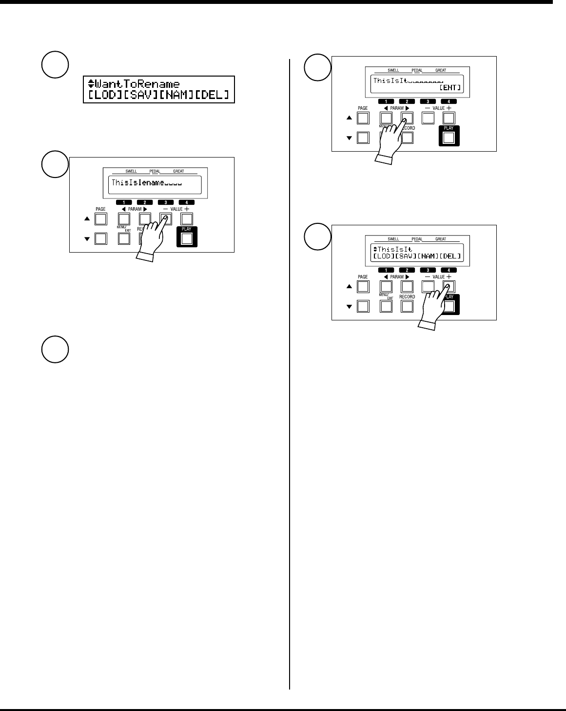
Naming the BANK ............................................................................... 60
VOLUME ....................................................................................... 61
[MASTER VOLUME] Knob .................................................................. 61
Expression Pedal ................................................................................ 61
[VOLUME] T ................................................................................ 6
T