Black Glass526-382526-717526-333526-610526-054526-505
10
Installation Instructions
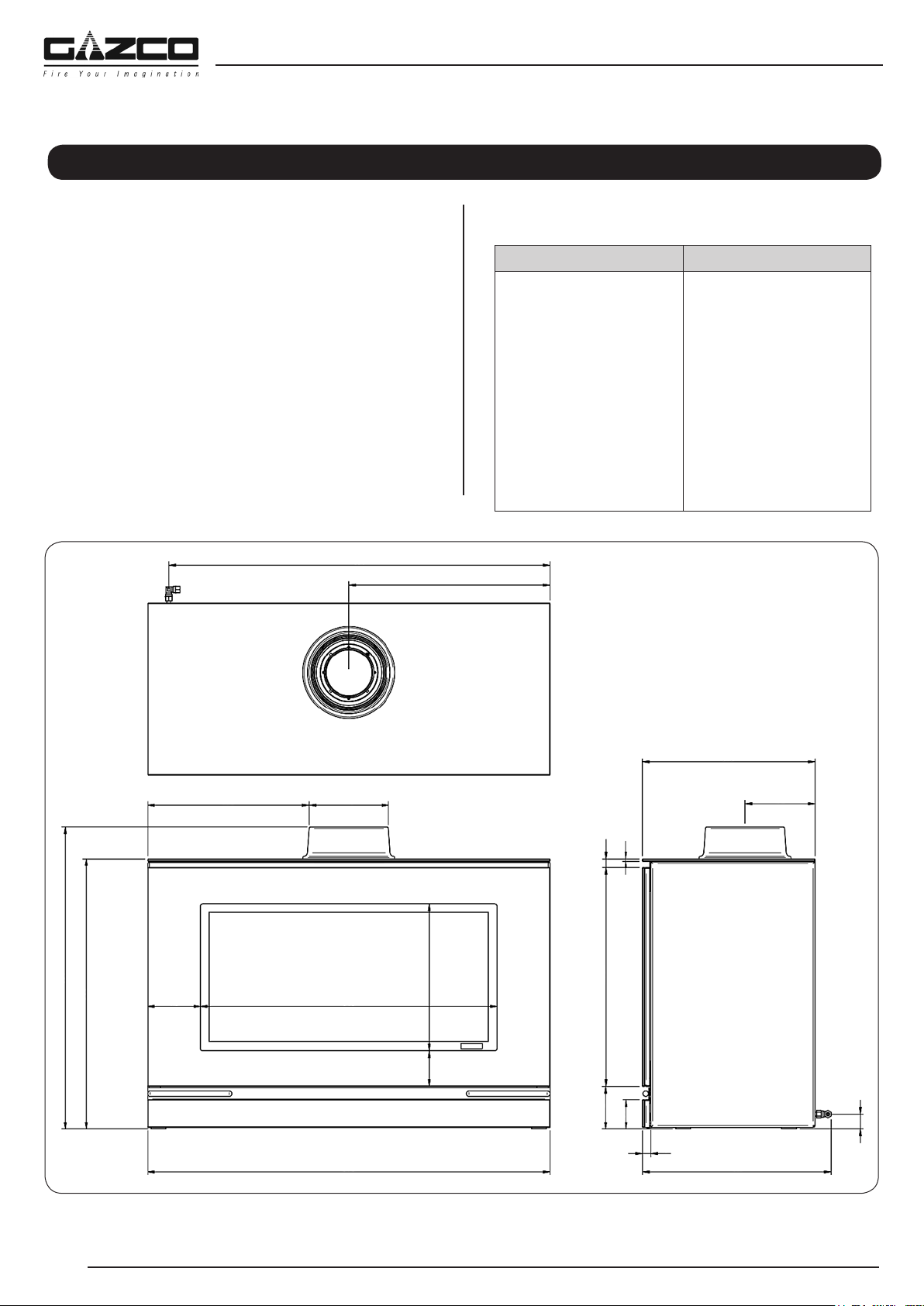
Technical Specification
657
830
438
352173
646115
876
588
32078
476
92
64
18
152
375
20
5
411
33
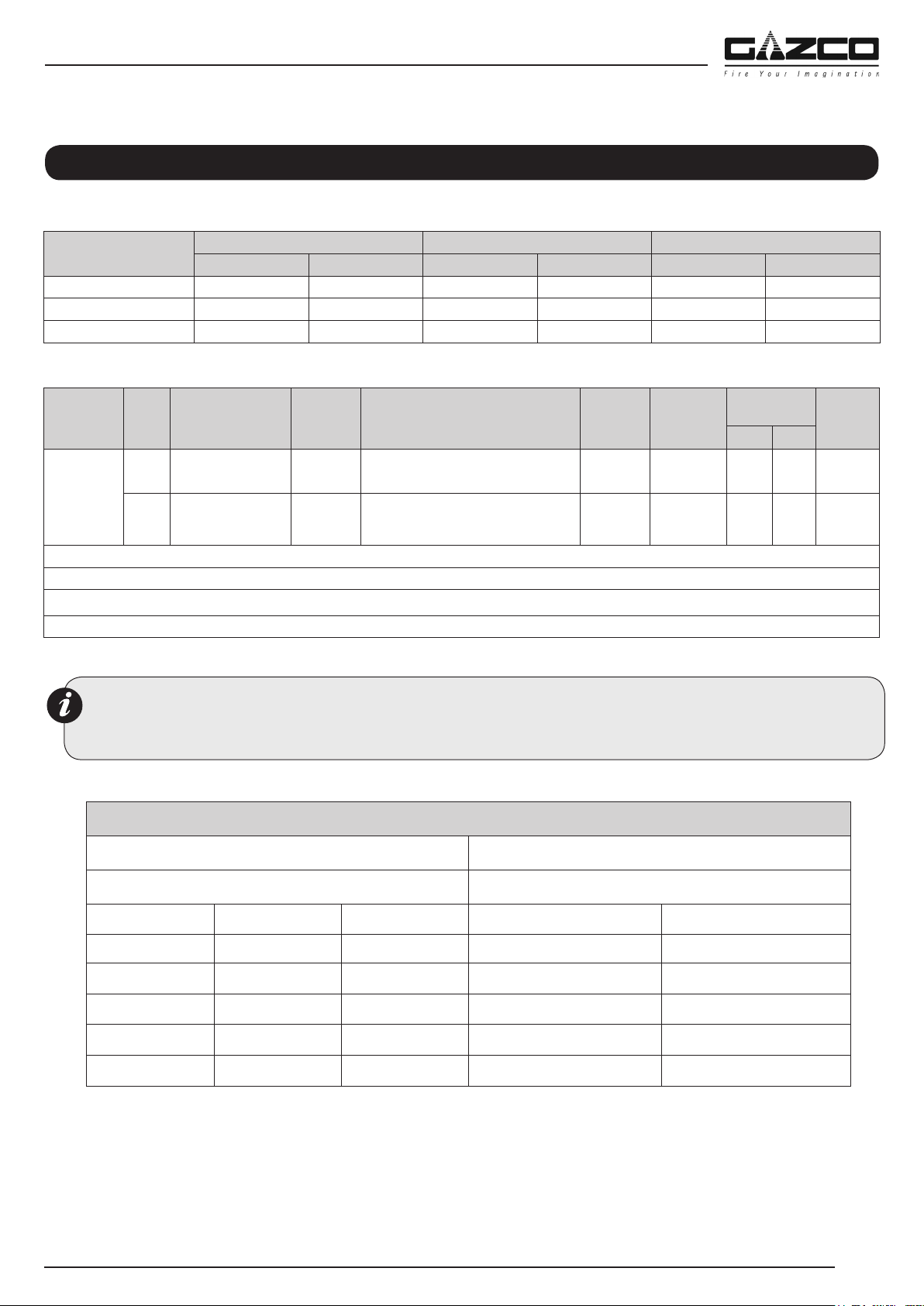
This appliance has been certified for use in countries other than
those stated. To install this appliance in these countries, it is
essential to obtain the translated instructions and in some cases
the appliance will require modification. Contact Gazco for further
information.
PACKING CHECKLIST
Qty DescriptionFixing Kit containing:
Stone & Pebble Effect
Version
1 x White Stone Chippings
1 x Pebble Set
Log Version
1 x Log Set
1 x Lava Rock
1 x Slate
Driftwood Log Version
1 x Driftwood Log Set
1 x Lava Rock
1 x Slate
1 x Instruction Manual
1 x Handset
1 x Quick Start Guide
1 x Door Tool
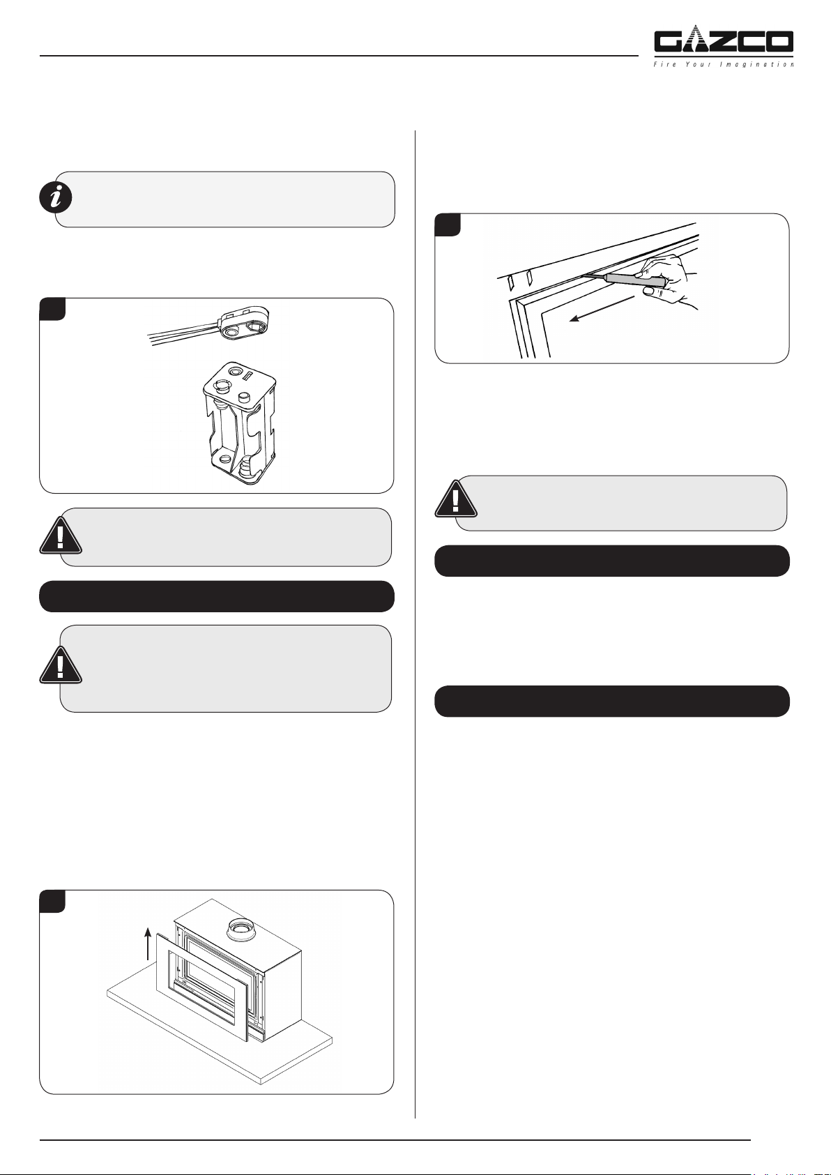
4 x AA cell batteries
1 x 9v cell battery
2 x Wood Screws
2 x Rawlplugs
2 x Base Installation Plate
2 x Wing Nuts
2 x Washers
2 x Pozi Screws
1 x Bag Embaglow material
11
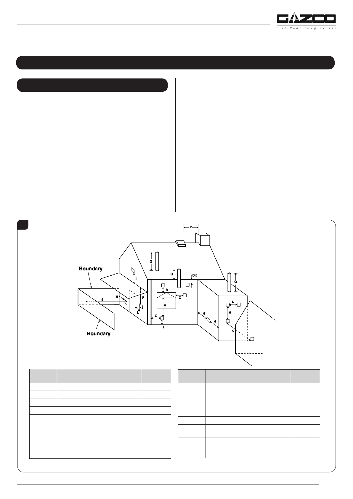
1. Flue and Chimney Requirements
Note: This appliance must only be installed with the flue
supplied.
You must adhere to the following:
1.1 The flue must be sited in accordance with BS5440: Part 1
(latest edition), see Diagram 1.
1.2 Fit a guard to protect people from any terminal less than 2
metres above any access such as level ground, a balcony
or above a flat roof.
1.3 All vertical and horizontal flues must be securely fixed and
fire precautions followed in accordance with local and
national codes of practice.
1.4 A restrictor may be required. Refer to Technical
Specifications on page 9.
1.5 Two types of flue terminals are available, horizontal and
vertical.
1.6 To measure for a horizontal terminal decide on the terminal
position.
1.7 Measure the height from the top of the appliance to the
centre of the required outlet.
1.8 For minimum and maximum flue dimensions see Diagrams 1A.
1.9 Allow enough room either above or to the side of the
appliance to assemble the flue on top.
1.10 Assemble a horizontal flue in the following order:
- Vertical section
- 90° elbow
- Horizontal plus terminal
1.11 Support the opening of a masonry installation with a lintel.
1.12 Only the horizontal terminal section can be reduced in size.
Installation Instructions
Site Requirements
UK Dimensions
1
DimensionTerminal PositionMinimum
Distance
ADirectly below an opening600mm
BAbove an opening300mm
CHorizontally next to an opening400mm
DBelow gutters, soil pipes or drain pipe300mm
EBelow eaves300mm
FBelow balcony or car port roof600mm
GFrom a vertical drain pipe or soil pipe300mm
HFrom an internal or external corner or to a
boundary alongside the terminal
600mm
IAbove ground, roof or balcony level300mm
DimensionTerminal PositionMinimum
Distance
JFrom a surface or boundary facing the
terminal
600mm
KFrom a terminal facing the terminal600mm
LFrom an opening in the car port (e.g. door,
window) into the dwelling
1200mm
MVertically from a terminal on the same wall1200mm
NHorizontally from a terminal on the same
wall
300mm
PFrom a structure on the roof600mm
QAbove the highest point of intersection with
the roof
300mm
* In addition, the terminal should not be nearer than 300mm to an opening in the building fabric formed for the purpose of accommodating a built-in element such as a window frame.
29
Servicing Instructions - Replacing Parts
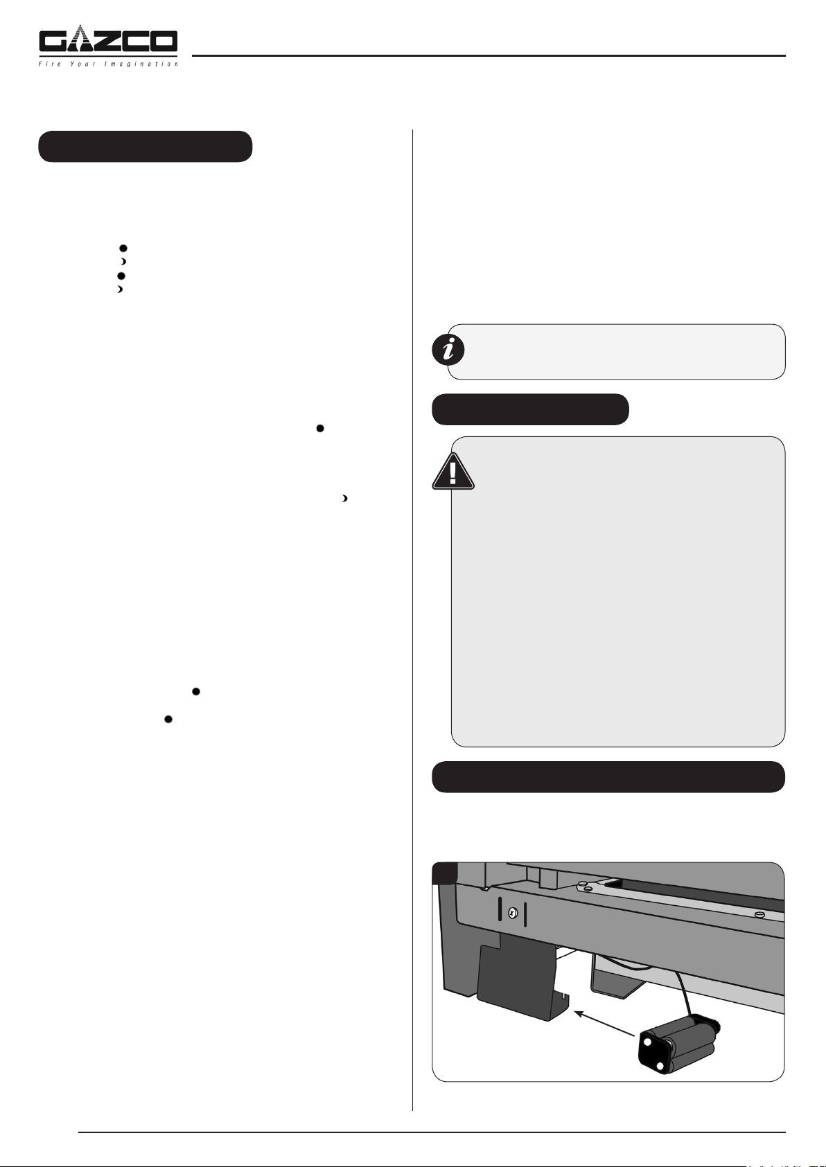
To completely remove the glass front:
3.3 Remove the securing spring clip from the bottom-right of the
window frame, see Diagram 3.
3
3.4 With the window frame in an upright position slide the frame
to the left so that it comes off the left hinge pin.
3.5 Still keeping the frame upright drop the left side down and
forward slightly, see Diagram 4.
4
3.6 Slide the frame to the right so it comes off the right hinge
pin. The window frame should now be free.
3.7 Refit in reverse order.
3.8 When closing the door ensure the door catches are fully
engaged.
UNDER NO CIRCUMSTANCES SHOULD THE
APPLIANCE BE USED WITHOUT THE CATCHES
HOLDING THE DOOR IN PLACE.
4. Glass Window
4.1 Remove the 2 clips and brackets from either side of the
frame, see Diagram 5.
5
4.2 Lift the glass clear from the lock bracket at the top of the
frame and slide out.
1. General
1.1 All main components can be replaced without removing the
appliance from its installation.
IT IS ESSENTIAL THAT THE GAS SUPPLY TO THE
APPLIANCE IS TURNED OFF AT THE ISOLATION
DEVICE BEFORE PROCEEDING FURTHER.
1.2 DISCONNECT BATTERIES BEFORE SERVICING THE
APPLIANCE.
1.3 Removal of Flue
If, for any reason, the flue has to be removed from the
appliance, the seal must be replaced in the inner spigot.
1.4 Access to the controls is restricted and the whole of the
control assembly is to be removed as one unit, see
Servicing Section 8.
2. Decorative Front
IMPORTANT: THE OUTER PANELLING OF THE
VISION IS MADE FROM GLASS. USE CAUTION
WHEN INSTALLING, REMOVING AND STORING AS
THE COMPONENTS ARE FRAGILE AND COULD
BREAK UNLESS HANDLED CAREFULLY.
1
2.1 Lift the front off the main body and pull forward.
3. Window Frame Assembly
3.1 To open the glass door use the hexagon key provided.
3.2 Release the window locks by moving them from shut to
Libble takes abuse of its services very seriously. We're committed to dealing with such abuse according to the laws in your country of residence. When you submit a report, we'll investigate it and take the appropriate action. We'll get back to you only if we require additional details or have more information to share.
Product:
Forumrules
To achieve meaningful questions, we apply the following rules:
First, read the manual;
Check if your question has been asked previously;
Try to ask your question as clearly as possible;
Did you already try to solve the problem? Please mention this;
Is your problem solved by a visitor then let him/her know in this forum;
To give a response to a question or answer, do not use this form but click on the button 'reply to this question';
Your question will be posted here and emailed to our subscribers. Therefore, avoid filling in personal details.
Register
Register getting emails for Gazco Vision Large Balanced Flue at:
new questions and answers
new manuals
You will receive an email to register for one or both of the options.
Get your user manual by e-mail
Enter your email address to receive the manual of Gazco Vision Large Balanced Flue in the language / languages: English as an attachment in your email.
The manual is 5.82 mb in size.
You will receive the manual in your email within minutes. If you have not received an email, then probably have entered the wrong email address or your mailbox is too full. In addition, it may be that your ISP may have a maximum size for emails to receive.
The manual is sent by email. Check your email
If you have not received an email with the manual within fifteen minutes, it may be that you have a entered a wrong email address or that your ISP has set a maximum size to receive email that is smaller than the size of the manual.
The email address you have provided is not correct.
Please check the email address and correct it.
Your question is posted on this page
Would you like to receive an email when new answers and questions are posted? Please enter your email address.