AB
The map configuration options page also features a map calibration function that
allows you to calibrate the map display your exact physical surroundings or to cor-
rect data from older charts. Before using the map calibration function, check to
make sure that your map datum selected on the GPS matches the datum on the
chart you are using (see page 61). To calibrate the map display, you must know
exactly where you are, and understand that the correction is generally valid only in
a limited range from the point of correction.
Map calibration should only be performed while the vessel is not moving, and
should never be used to attempt SA corrections, which can degrade accuracy up to
330 (100 meters). The maximum correction is 16,400 feet (5000m).
To calibrate the map:
1. Select the Calibrate the Map? option and press
T
.
2. Use the
R
keypad to move the arrow cursor from the satellite
position (indicated by the satellite icon) to your exact position. The
bearing, distance, and position will be indicated in the data window.
3. Press
T
to confirm the calibration offset.
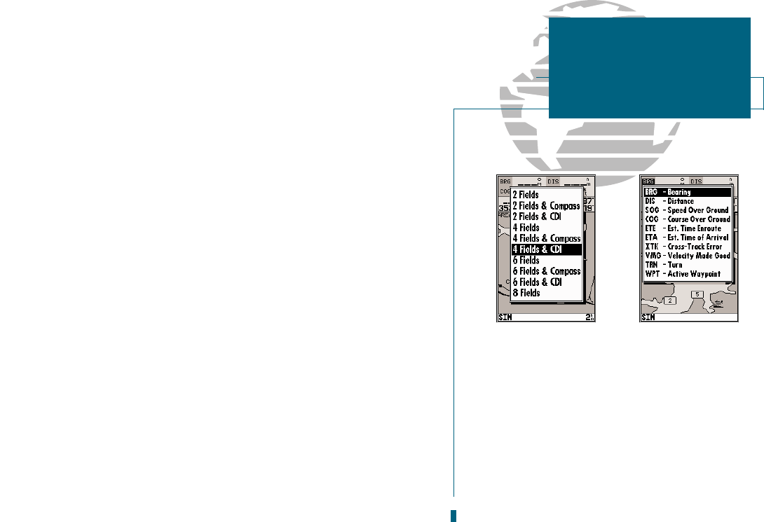
The next option available from the map configuration page is the set map colors
option, which allows you to define the fill color (grayscale) of the land and water
used on the map display. Three options are available: no color (no fills for land or
water), gray land/white water (the default setting), and white land/gray water.
To select a map colors option:
1. Select the Set Map Colors? option and press
T
.
2. Highlight the desired map color option and press
T
.
The map configuration options page also features a restore defaults function that
can be used to quickly restore all map configuration options to the factory settings.
To restore the map configuration options to the factory defaults:
1. Highlight the Restore Defaults? settings and press
T
.
28
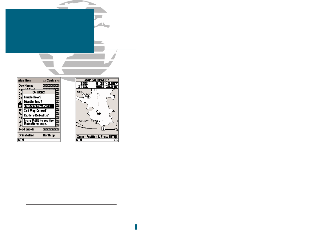
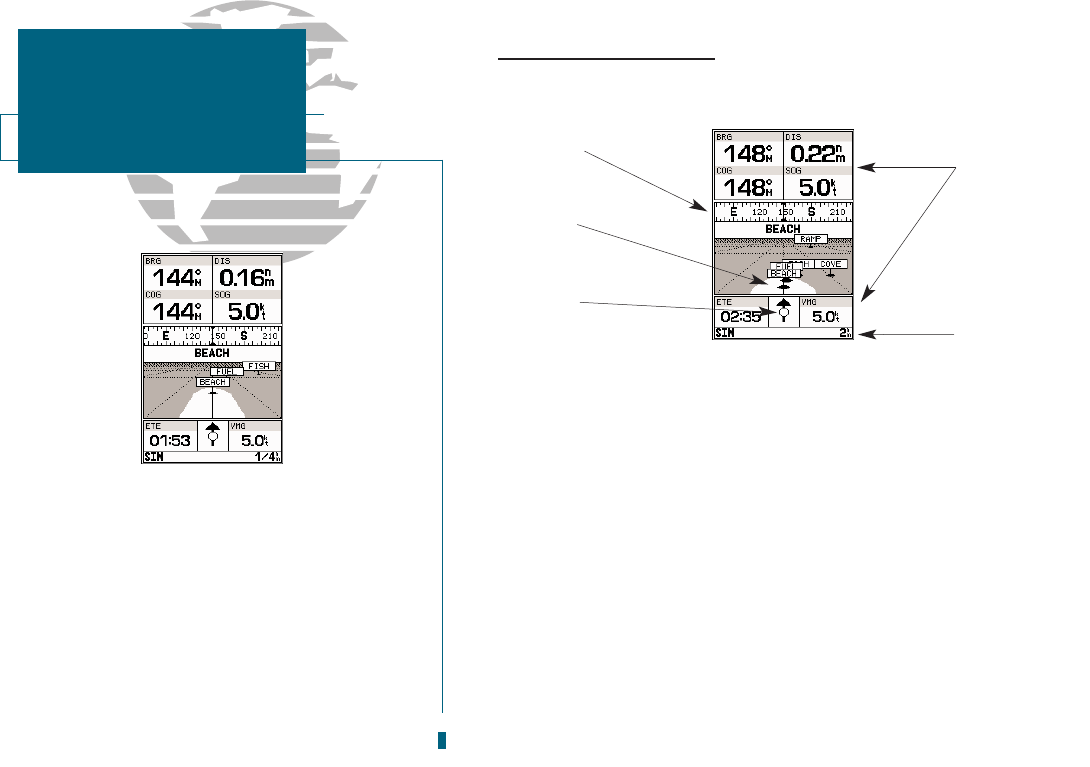
A. To calibrate the map, highlight the Calibrate
the Map? option and press EDIT/ENTER.
B. A satellite icon will remain on the map to
indicate the GPS position, while the boat
marker will move to reflect the calibration
changes.
CAUTION!
The map calibration function should never be
used to attempt correcting for Selective
Availability errors.
SECTION
3
MAP PAGE
Map Configuration
& Map Colors