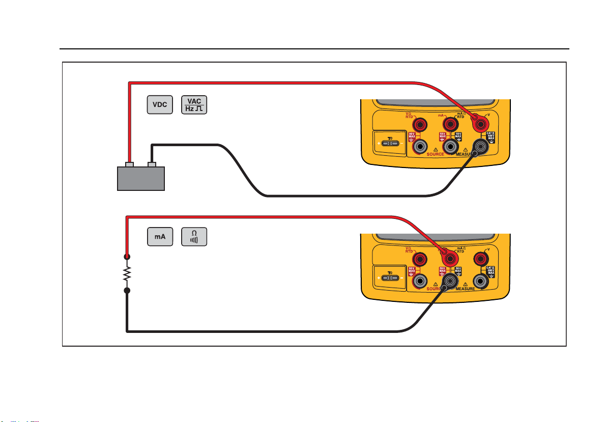
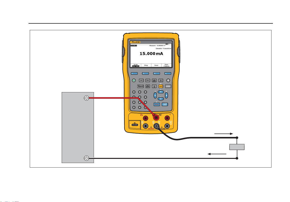
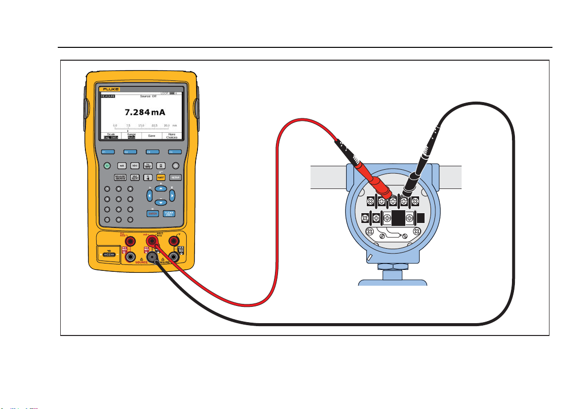
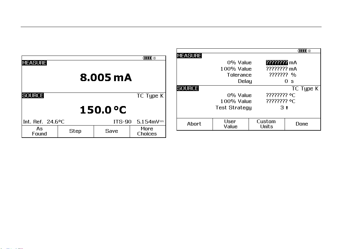
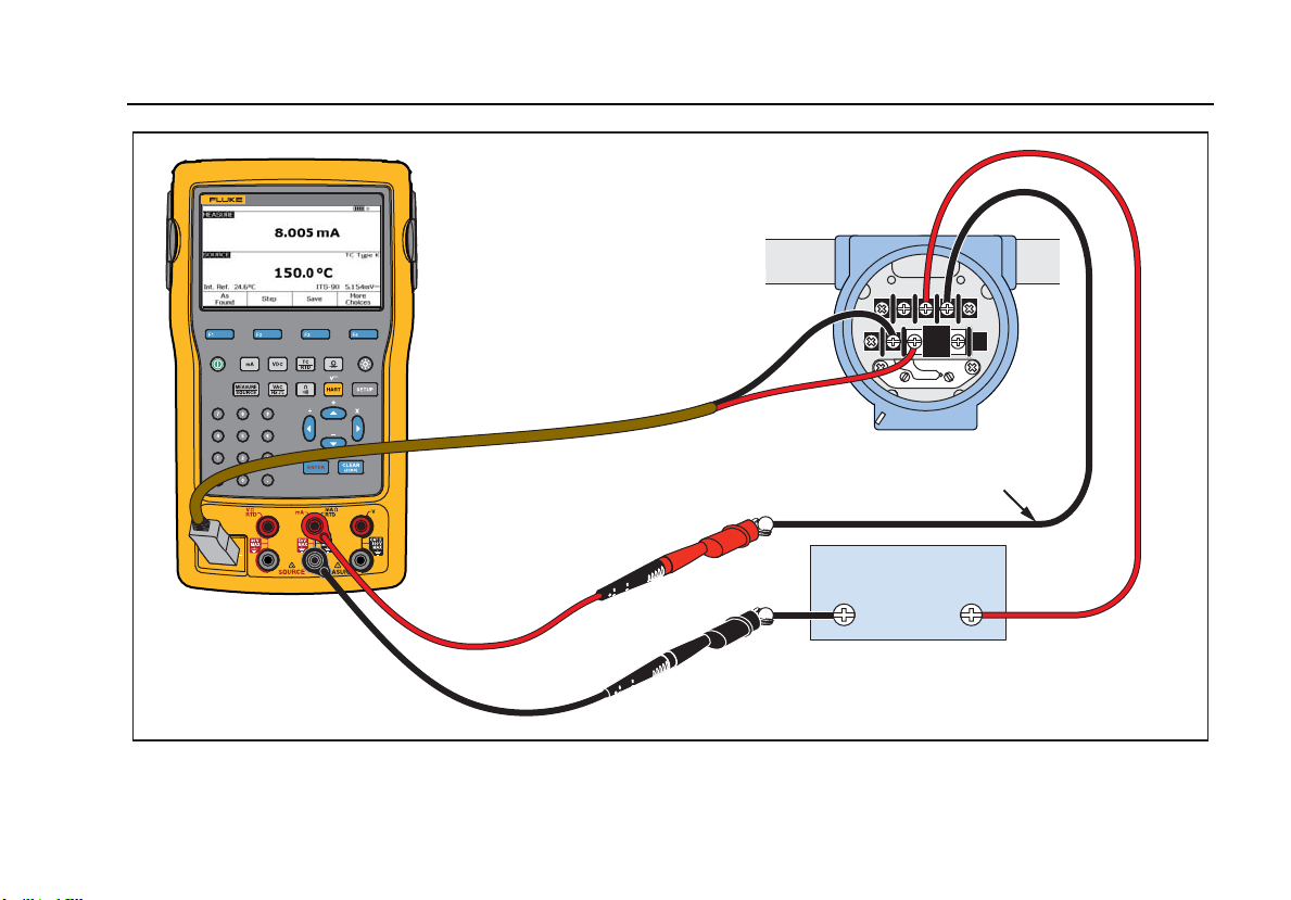
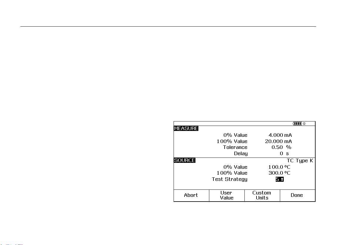
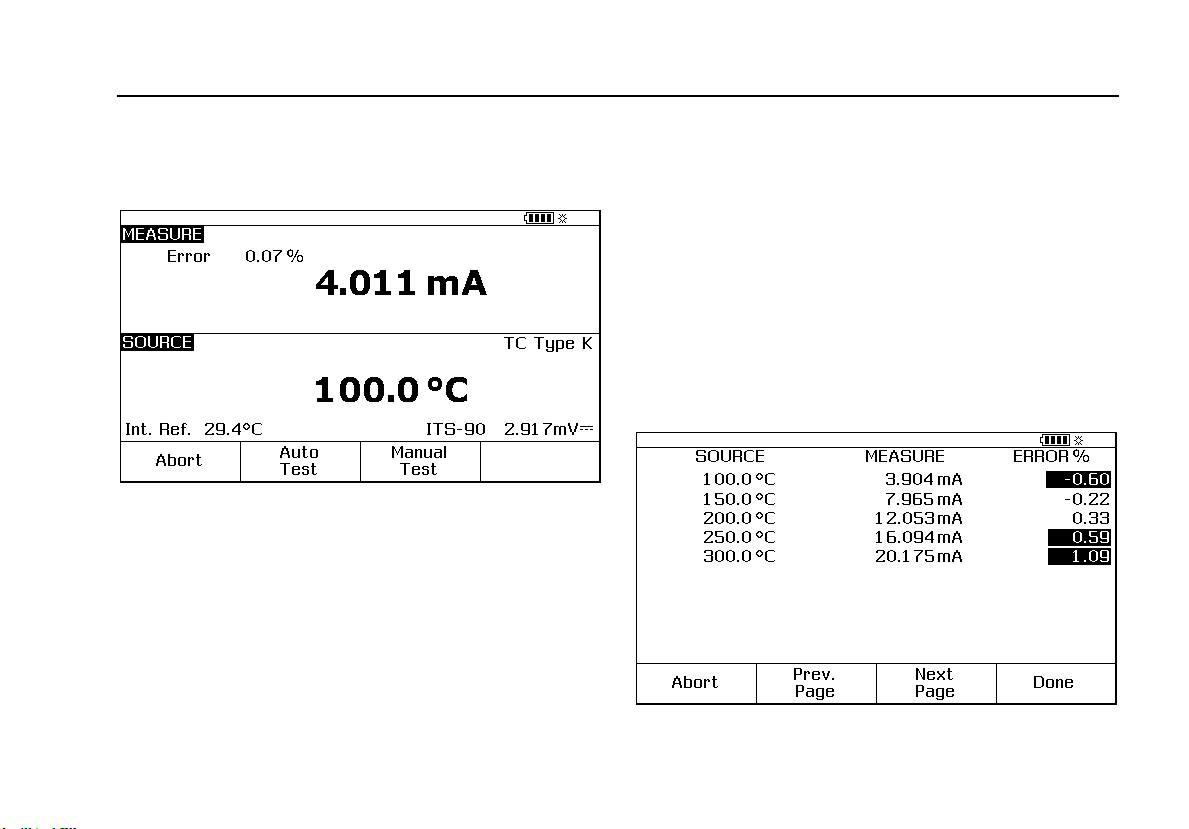
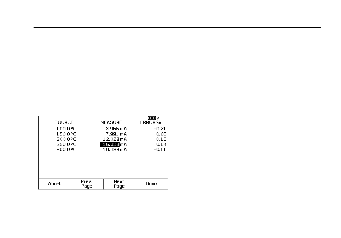
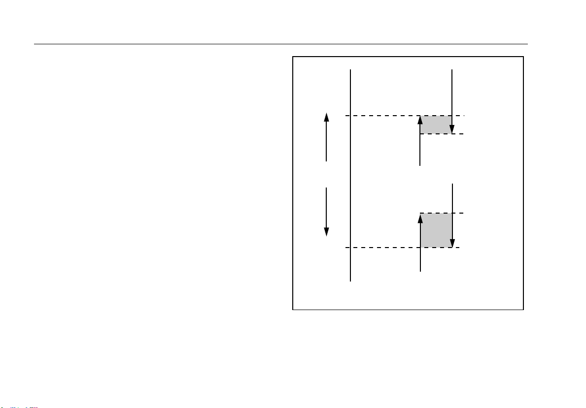
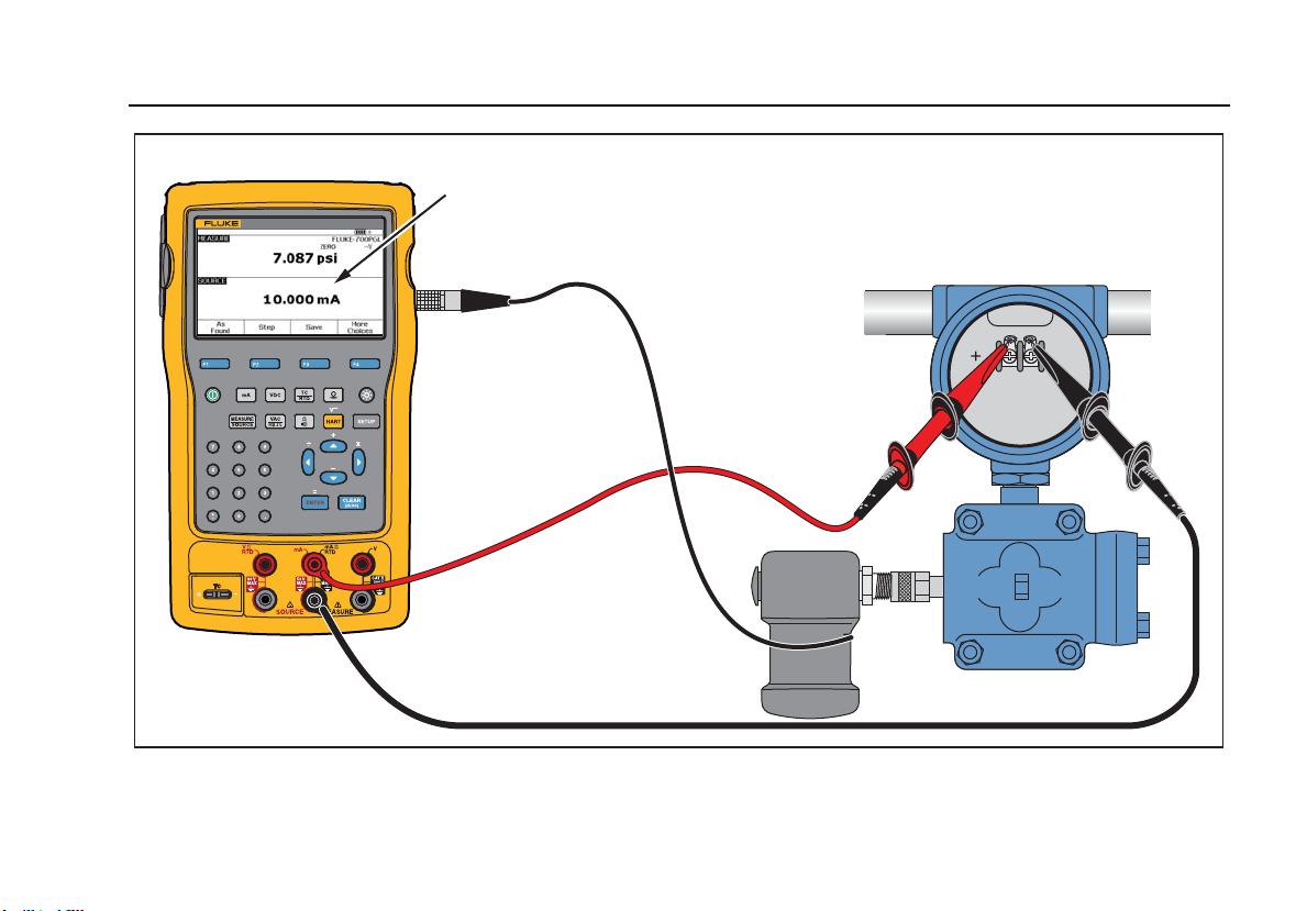
Figure 47. Output Current of a Transmitter Measurement
Documenting Process Calibrator
Quick Guide to Applications
93
754
DOCUMENTING PROCESS CALIBRATOR
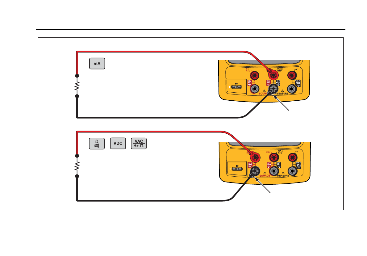
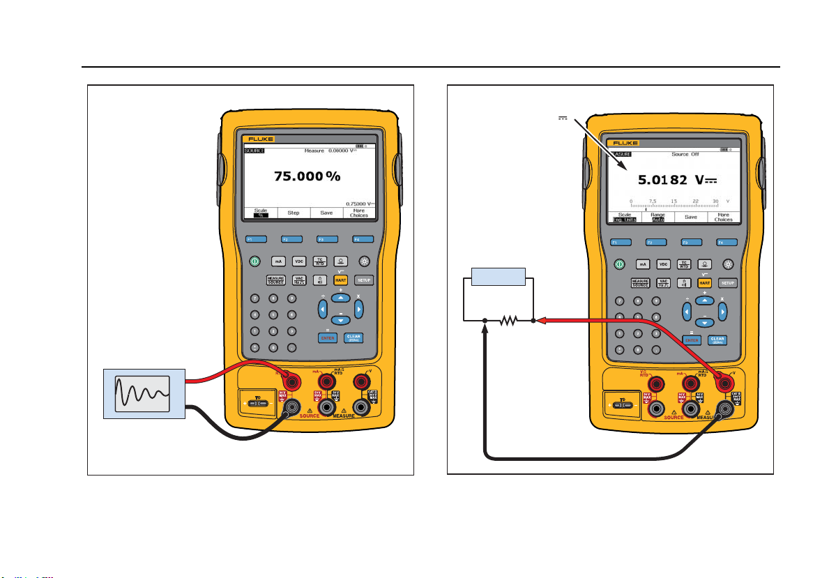
Measure
Resistance
gks30c.eps
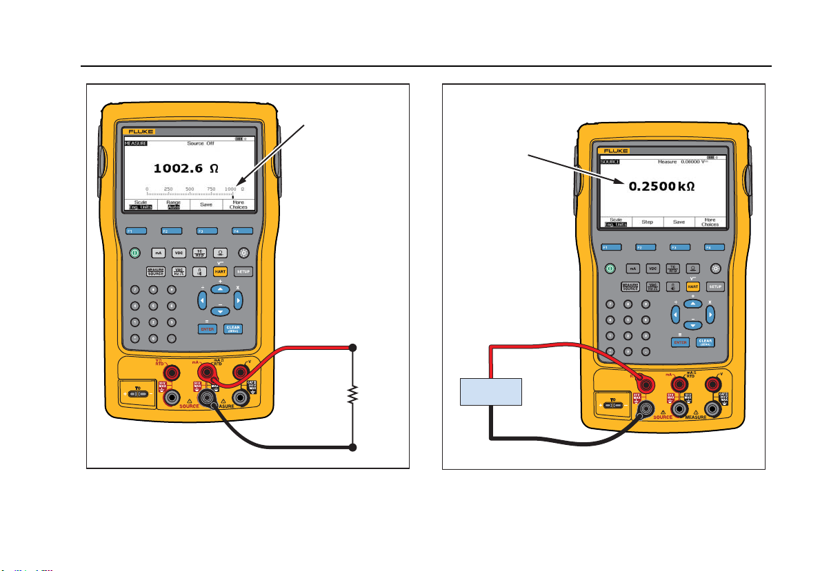
Figure 48. Precision Resistor Measurement
754
DOCUMENTING PROCESS CALIBRATOR
Source
Resistance
Circuit
gks31c.eps
Figure 49. Resistance Source
753/754
Users Manual
94
754
DOCUMENTING PROCESS CALIBRATOR
Measure
Continuity
gks32c.eps
Figure 50. Checking a Switch
754
DOCUMENTING PROCESS CALIBRATOR
Measure
Frequency
gks33c.eps
Figure 51. Tachometer Examination
Documenting Process Calibrator
Quick Guide to Applications
95
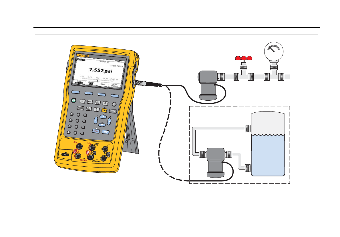
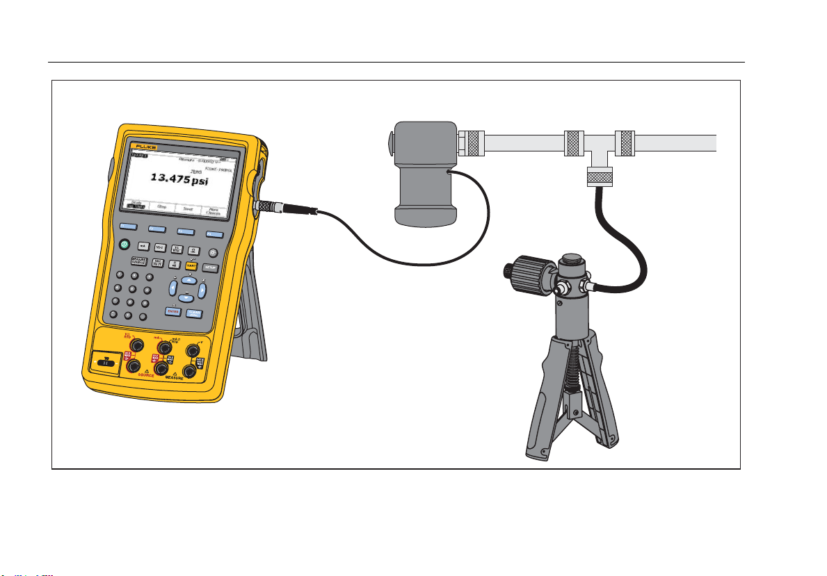
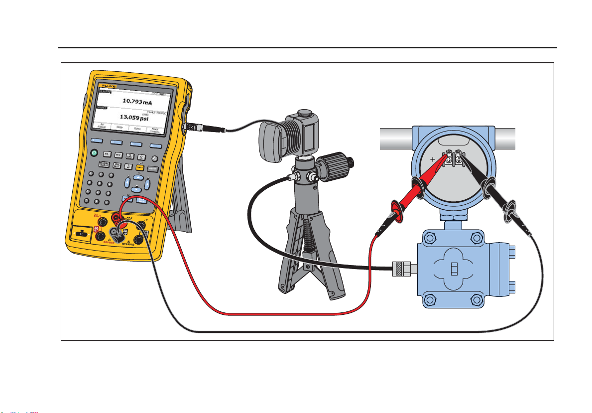
Hand Pump
Pressure
Module
754
DOCUMENTING PROCESS CALIBRATOR
Measure mA
Source Pressure
Loop Power Enabled
gks34c.eps
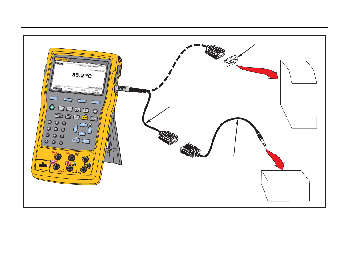
Figure 52. Analog and HARTPressure Transmitter Connection
753/754
Users Manual
96
754
DOCUMENTING PROCESS CALIBRATOR
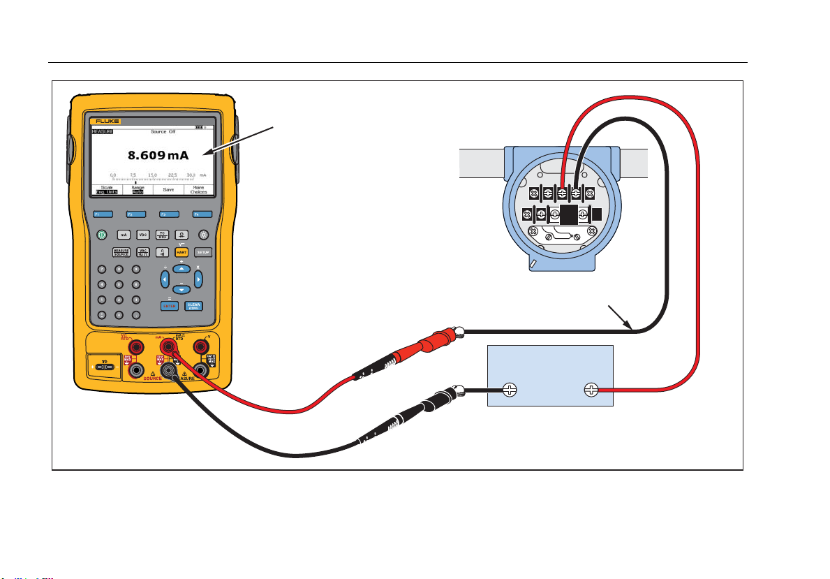
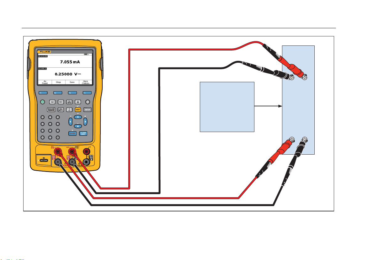
–+
+–
Output
Input
Input
0 – 1mV, 0 – 10mV,
0 – 100mV, 1 – 5V,
0 – 1V, 0 – 10V
Output
4 – 20 mA
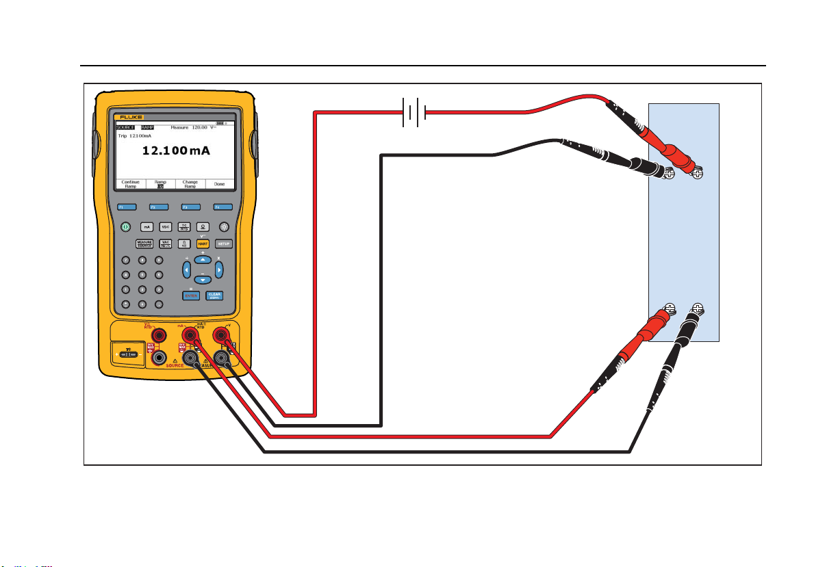
Source mV or V
Measure mA
gks35c.eps
Figure 53. mV to Current Transmitter Calibration
Documenting Process Calibrator
Quick Guide to Applications
97
754
DOCUMENTING PROCESS CALIBRATOR
Measure
Frequency
gks36c.eps
Figure 54. Vortex Shedding Flowmeter Check
753/754
Users Manual
98
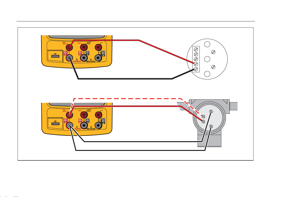
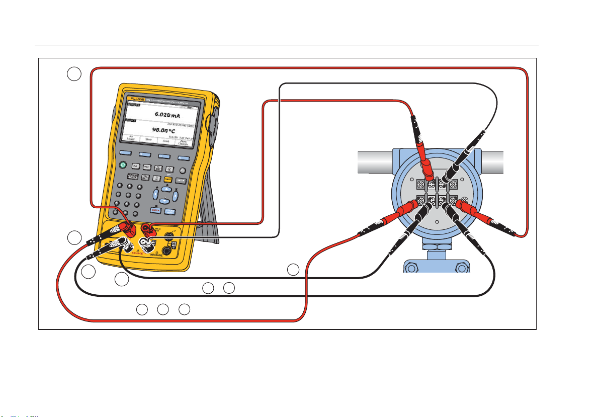
+–
A
A
B
C
A
2-Wire RTD=
A
3-Wire RTD= +B
A
4-Wire RTD= +B
C
+
gks60.eps
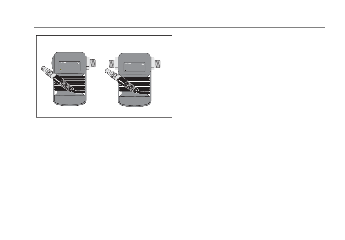
Figure 55. HART and Analog RTD Transmitter Connections
Documenting Process Calibrator
Quick Guide to Applications
99
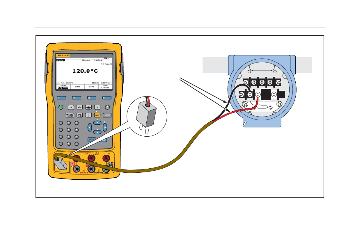
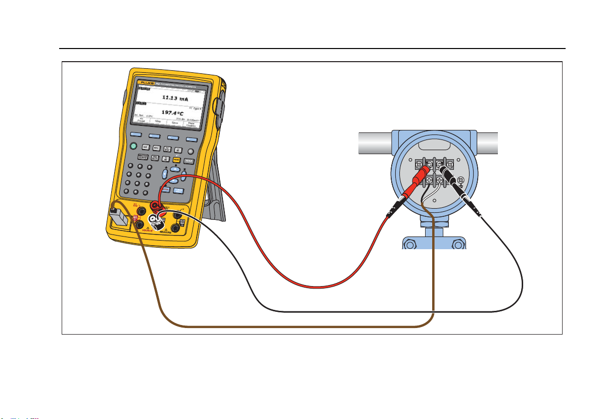
+–
gks61.eps
Figure 56. Analog and HART Thermocouple Transmitter Connections
753/754
Users Manual
100
gks43.eps
Figure 57. Transmitter HART- Comm Only
Documenting Process Calibrator
Communication with a PC
101
Communication with a PC
Procedures and results that you have kept can be
uploaded from and downloaded to a PC. A PC, Microsoft
Windows, USB cable (supplied), and Fluke DPCTrack2
application software, or a qualified Fluke partner’s
software are required. See the DPCTrack2 Users Manual
for further instructions.
Maintenance
Warning
To prevent possible electrical shock, fire, or
personal injury:
•Have an approved technician repair the
Product.
•Do not operate the Product with covers
removed or the case open. Hazardous
voltage exposure is possible.
•Remove the input signals before you
clean the Product.
•Use only specified replacement parts.
Note
Additional maintenance instructions, including a
calibration procedure and a list of replaceable
parts is available in the 75X Series Calibration
Manual available from the Fluke website.
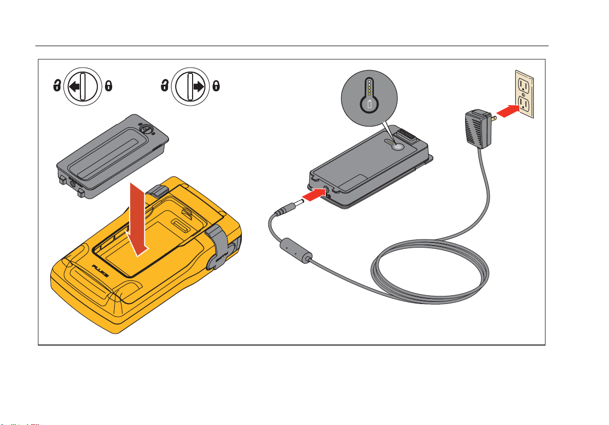
Battery Replacement
Replace the battery when it no longer holds a charge for
the rated interval. The battery normally lasts for up to 300
charge/discharge cycles. To order a replacement battery,
see “Contacting Fluke” and “User-Replaceable Parts”.
Note
Spent batteries should be disposed of by a
qualified recycler or hazardous materials
handler. Contact an authorized Fluke Service
Center for recycling information.
Clean the Product
Clean the Product and pressure modules with a soft cloth
dampened with water or water and mild soap.
Caution
To prevent possible damage to the Product,
do not use solvents or abrasive cleansers.
753/754
Users Manual
102
Calibration Data
The date of the last calibration and verification shows on
the calibration sticker and on the calibration screen in
Setup mode. The CAL. STATUS number on the sticker
should always match the Calibration Status number in the
calibration screen. Calibration of the Product is to be done
by qualified personnel. See the 75X Series Calibration
Manual available at the Fluke website.
In Case of Difficulty
Warning
To avoid possible electric shock or personal
injury, do not use the Product if it operates
abnormally. Protection may be impaired.
When in doubt, have the Product serviced.
If the display is blank or unreadable, but the beeper works
when the Product is turned on, make sure the brightness
is correctly adjusted. To adjust the Intensity, see “Display
Intensity”.
If the Product will not turn on, make sure the battery is not
dead or disconnected from the battery charger. If the
Product receives power, the power button should be lit. If
the button is lit, but the Product does not power up, have
the Product serviced. See “How to Contact Fluke”.
Service Center Calibration or Repair
Calibration, repairs, or servicing not included in this
manual must be done only by qualified service personnel.
If the Product fails, examine the battery pack first, and
replace it if necessary.
Make sure that you operate the Product in accordance
with the instructions in this manual. If the Product is faulty,
send a description of the failure with the Product.
Pressure modules do not need to accompany the Product
unless the module is faulty also. Be sure to pack the
Product securely, using the original shipping container if it
is available. See “How to Contact Fluke” and the Warranty
Statement.
User-Replaceable Parts
Table 12 lists the Fluke part number of each user-
replaceable part for the Product. See “Standard
Equipment” and “Accessories” for model or part numbers
of standard and optional equipment.
Documenting Process Calibrator
User-Replaceable Parts
103
Table 12. Replacement Parts
Item Fluke Part Number
Adjustable Quick-Release Strap 3889532
Input/Output Jack Decal 3405856
Tilt Stand 3404790
BP7240 Battery 4022220
USB Cable 1671807
BC7240 Power Supply/Battery Charger 4022655
Lens Cover 3609579
Alligator Clip Set-Extended Tooth 3765923
754HCC HART Communication Cable Assembly 3829410
AC280 Suregrip Hook Clip Set 1610115
TC Cap 4073631
Note: See “Standard Equipment” and “Accessories” for model or part numbers for most replaceable equipment.
753/754
Users Manual
104
Accessories
The Fluke accessories listed below are compatible with
the Product. For more information about these
accessories and their prices, contact a Fluke
representative.
•700-IV Current Shunt
•DPCTrack2 software
•C799 Soft Carry Case
•BC7240 Replacement Battery Charger/Universal
Power Supply
•HART Drywell Cable Accessory (PN 2111088)
•12-V Car Battery Charger
•Fluke-700PCK Pressure Module Calibration Kit
(requires pressure calibration equipment and a PC
compatible computer)
•700PTP-1 Pneumatic test pump
•700HTP-1 Hydraulic test pump
•Fluke-700TC1 TC miniplug kit
•Fluke-700TC2 TC miniplug kit
•C781 Soft Carrying Case
•C700 Hard Carrying Case
•BP7240 Li-Ion Battery
•TL series test leads
•AC series test lead clips
•TP series test lead probes
•80PK series thermocouples
•Pressure Modules Fluke model numbers listed
below. (Differential models also operate in gage
mode.) Contact a Fluke representative about
pressure modules not listed here.
•FLUKE-700P00 1 in. H2O/0.001
•FLUKE-700P01 10 in. H2O/0.01
•FLUKE-700P02 1 psi/0.0001
•FLUKE-700P22 1 psi/0.0001
•FLUKE-700P03 5 psi/0.0001
•FLUKE-700P23 5 psi/0.0001
•FLUKE-700P04 15 psi/0.001
•FLUKE-700P24 15 psi/0.001
•FLUKE-700P05 30 psi/0.001
•FLUKE-700P06 100 psi/0.01
Documenting Process Calibrator
Accessories
105
•FLUKE-700P27 300 psi / 0.01
• FLUKE-700P07 500 psi/0.01
•FLUKE-700P08 1000 psi/0.1
•FLUKE-700P09 1500 psi/0.1
•FLUKE-700PA3 5 psi/0.0001
•FLUKE-700PA4 15 psi/0.001
•FLUKE-700PA5 30 psi/0.001
•FLUKE-700PA6 100 psi/0.01
•FLUKE-700PV3 -5 psi/0.0001
•FLUKE-700PV4 -15 psi/0.001
• FLUKE-700PD2 ±1 psi/0.0001
• FLUKE-700PD3 ±5 psi/0.0001
• FLUKE-700PD4 ±15 psi/0.001
•FLUKE-700PD5 -15/30 psi/0.001
•FLUKE-700PD6 -15/100 psi/0.01
•FLUKE-700PD7 -15/200 psi/0.01
•FLUKE-700P29 3000 psi/0.1
•FLUKE-700P30 5000 psi/0.1
•FLUKE-700P31 10000 psi/1
753/754
Users Manual
106
Specifications
General Specifications
All specifications apply from +18 °C to +28 °C unless stated otherwise.
All specifications assume a 5-minute warmup period.
Measurement specifications are valid only when Damping is turned on. When damping is turned off, or when the annunciator is shown,
floor specifications are multiplied by 3. Floor specifications are the second part of the specifications. The measure pressure, temperature,
and frequency functions are specified only with damping on.
Specifications are valid to 110 % of range. The following exceptions are valid to 100 % of range: 300 V dc, 300 V ac, 22 mA source and
simulate, 15 V dc source, and temperature measure and source.
To achieve the best noise rejection, use battery power.
Size (H x W x L) ..................................................................... Height = 63.35 mm (2.49 inches) x Width = 136.37 mm (5.37 inches)
x Length = 244.96 mm (9.65 inches)
Weight .................................................................................... 1.23 kg (2.71 lb) (Batteries included)
Display ................................................................................... 480 by 272 pixel graphic LCD, 95 x 54 mm
Power ..................................................................................... Internal battery pack: Lithium Ion, 7.2 V dc, 30 Wh
Environmental Specifications
Operating Altitude ................................................................. 3000 m (9842 ft)
Storage Altitude .................................................................... 13000 m (42650 ft)
Operating Temperature ........................................................ -10 to 50 °C
Storage Temperature ........................................................... -20 to 60 °C
Relative Humidity (Maximum, non-condensing) ................ 90 % to 35 °C
75 % to 40 °C
45 % to 50 °C
Standards and Agency Approval Specifications
Protection Class .................................................................... Pollution Degree II IP 52
Documenting Process Calibrator
Detailed Specifications
107
Double Insulation Creepage and Clearance ....................... Per IEC 61010-1
Installation Category ............................................................. 300 V CAT II
EMI, RFI, EMC ........................................................................ EN 61326-1:2006
RF Fields ................................................................................ Accuracy for all functions is not specified in RF fields >3 V/m
Detailed Specifications
Specifications valid after a 5-minute warmup.
Specifications are valid to 110 % of Range with the following exceptions: 300 V dc measure, 300 V ac measure, 50 kHz measure and
source, 22 mA source and simulate, 15 V dc source, and temperature measure and source which are valid to 100 % of range.
Libble takes abuse of its services very seriously. We're committed to dealing with such abuse according to the laws in your country of residence. When you submit a report, we'll investigate it and take the appropriate action. We'll get back to you only if we require additional details or have more information to share.
Product:
Forumrules
To achieve meaningful questions, we apply the following rules:
First, read the manual;
Check if your question has been asked previously;
Try to ask your question as clearly as possible;
Did you already try to solve the problem? Please mention this;
Is your problem solved by a visitor then let him/her know in this forum;
To give a response to a question or answer, do not use this form but click on the button 'reply to this question';
Your question will be posted here and emailed to our subscribers. Therefore, avoid filling in personal details.
Register
Register getting emails for Fluke 753 at:
new questions and answers
new manuals
You will receive an email to register for one or both of the options.
Get your user manual by e-mail
Enter your email address to receive the manual of Fluke 753 in the language / languages: English as an attachment in your email.
The manual is 5,57 mb in size.
You will receive the manual in your email within minutes. If you have not received an email, then probably have entered the wrong email address or your mailbox is too full. In addition, it may be that your ISP may have a maximum size for emails to receive.
If you have not received an email with the manual within fifteen minutes, it may be that you have a entered a wrong email address or that your ISP has set a maximum size to receive email that is smaller than the size of the manual.
The email address you have provided is not correct.
Please check the email address and correct it.
Your question is posted on this page
Would you like to receive an email when new answers and questions are posted? Please enter your email address.