Corporation (NYSE: JAH). First Alert® is a registered trademark of the First Alert Trust. Due to continuing product development, the product inside
the packaging may look slightly different than the one on the package. To obtain warranty service, contact the Consumer Affairs Division at
1-800-323-9005, Monday through Friday, 7:30 a.m. - 5 p.m., Central Standard Time.
Made in China
Page 3
INTRODUCTION
KEY PRODUCT FEATURES
Main Description
Eight channel H.264 digital video recorder with Internet remote
surveillance, motion detection, PTZ and alarm control suitable for
applications such as high-end residential - new or remodel, light
commercial, small business/retail, small warehouse or small grocery.
Product features
•H.264 Compression & Virus free Linux O/S
•Record, playback, mobile phone live view, backup, control, & remote access
•500 GB or 1 TB SATA hard drive installed
•Supports smart phone live view & Email alarm
•Customizable Email alerts
•Supports 2-channel HD1 or 2-channel D1 and 6-channel
CIF Real-time simultaneous recording
•Supports 8-channel simultaneous playback
•User-friendly interface: DVR capable of providing 16 bit true color,
semi-transparent GUI with notes for selected menu items
•Advanced motion detection activated recording
•24/7 Scheduled Recording
•Supports D1, HD1, CIF and QCIF for recording quality
•Network monitoring through internet access
•Supports USB or external DVD backup
•Hi-speed backup/upgrade/record via USB2.0
•PTZ camera control
Connect wireless camera to wired DVR security system
Go to www.firstalert.com/howtoconnect
Page 4
SectionDeScriptionpage #
1Introduction2-3
2Safety6
3
Product Overview7
What is in the Box7
DVR Controls
Front Panel8
Back Panel9
Remote Control10
Mouse Controls11
Camera Power Connections12
Connecting Devices12
4
Initial Setup - System Operation13
System Start Up13
Power On/Off13
Main Menu Access (Quick Access Menu)14
Password Setup and User Permissions15
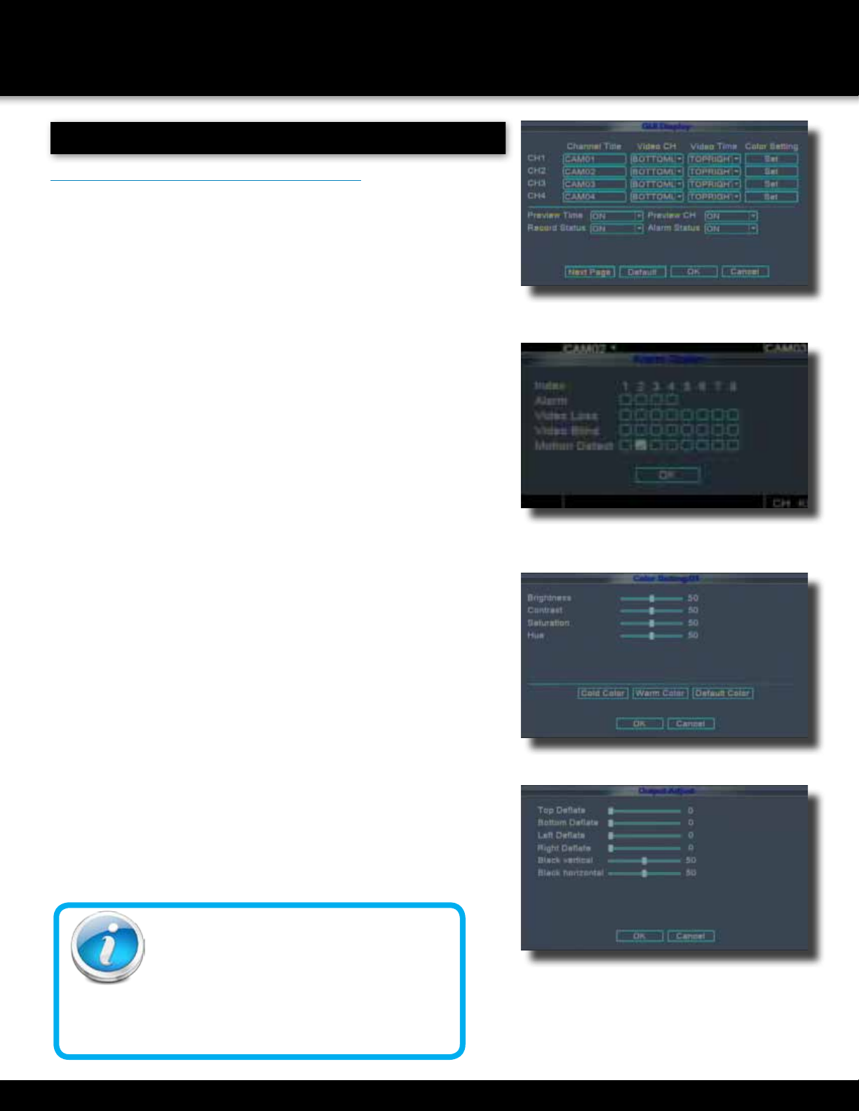
Camera Display Setup16
Language, Date and Time17
Display, Video/Audio17
Language, Date/Time and Daylight Savings Time (DST)17
5
Basic Operation18
Recording18
Configure Recording Options18
Recording Schedule (Timer Recording)18
Recording Schedule (TIMER RECORD) Example19
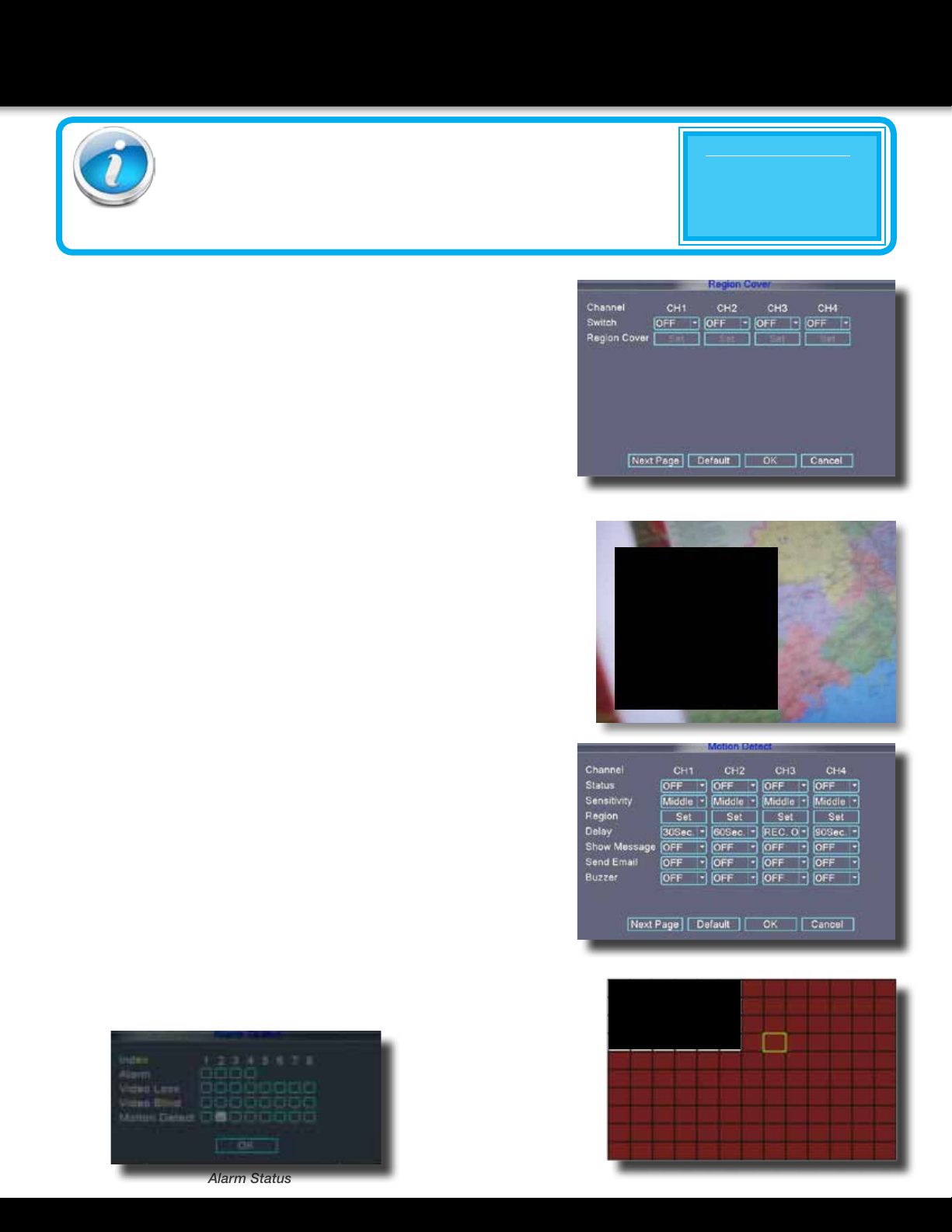
Privacy Mask Field19
Motion Detect Setup19
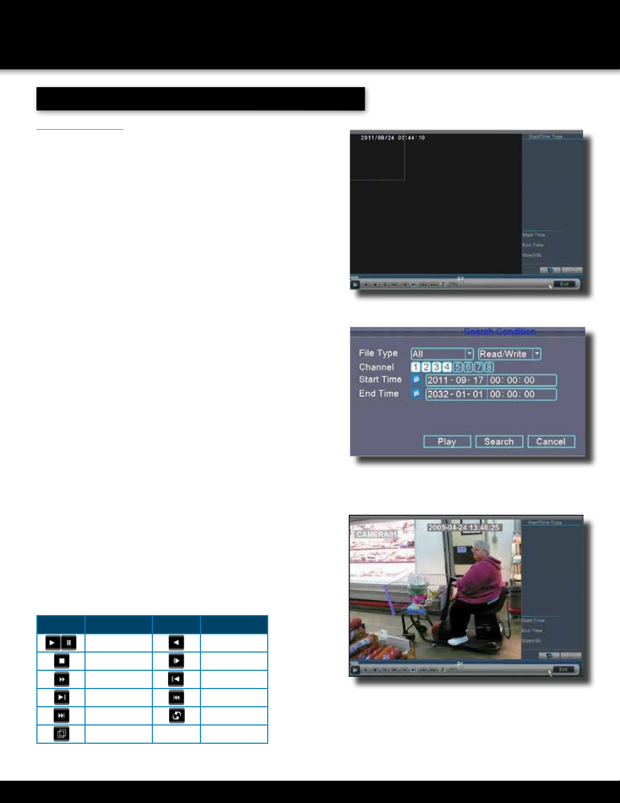
Playback20
Playback and Record Search20
On-Screen Playback Controls20
File List21
Backup21
HDD Management 21-22
INTRODUCTION
TABLE OF CONTENTS
Page 5
INTRODUCTION
TABLE OF CONTENTS
SectionDeScriptionpage #
6
Advanced Operation22
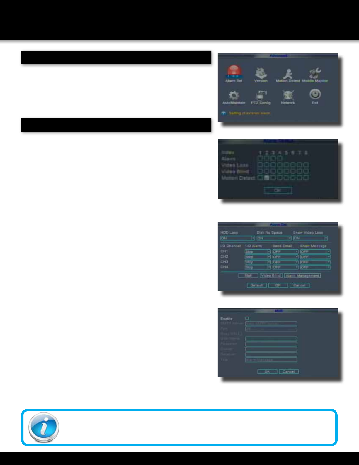
Alarm22-23
Alarm Setup22-23
Email Setup23
System Info and System Update24
System Maintain24
Upgrade Firmware24
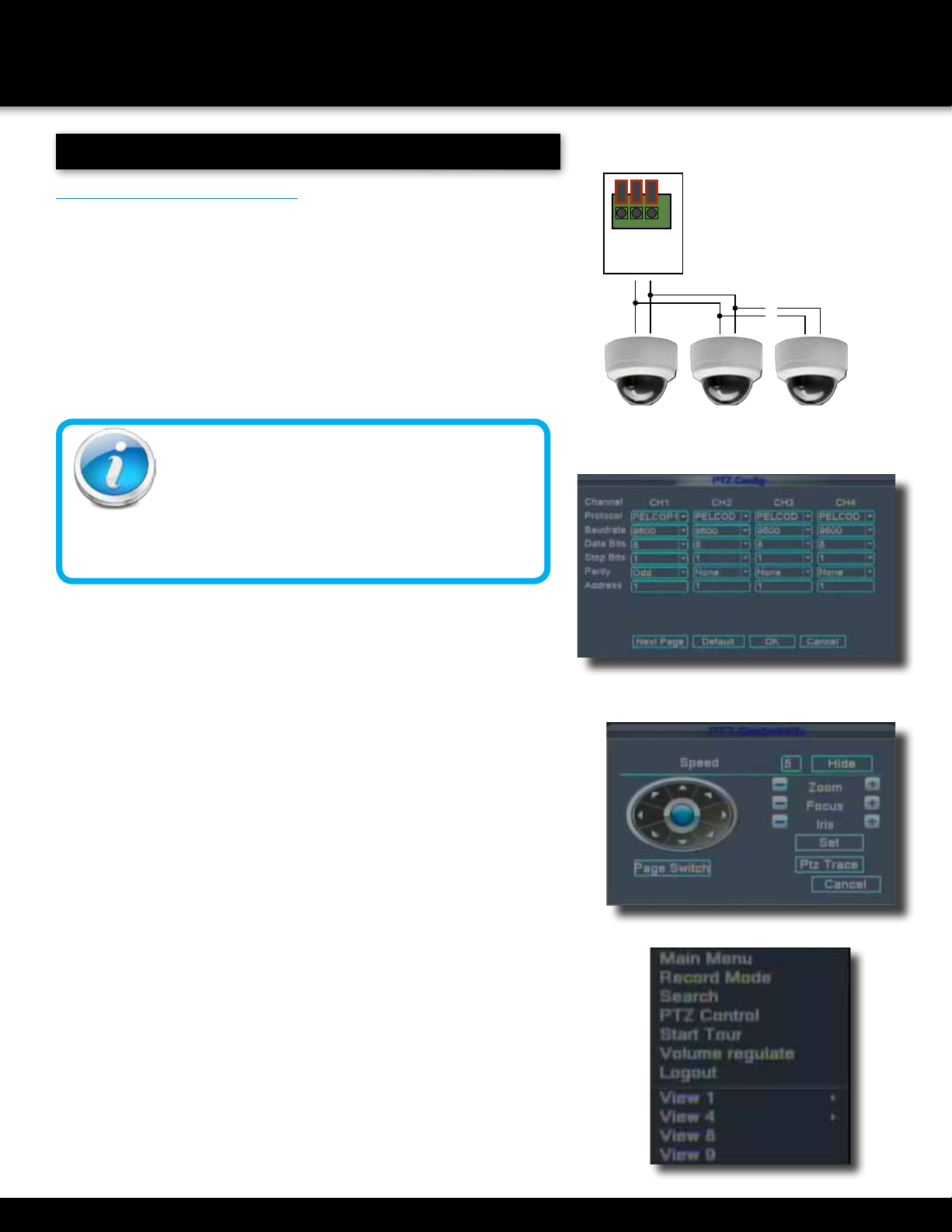
PTZ Setup and Control25-26
Step 1: Connect your PTZ Camera to this DVR25
Step 2: Configure PTZ Communication Settings25
Step 3: Configure the Operation and Control of your PTZ Camera(s)25
Step 4: Configure the CRUISE SETTING of your PTZ Camera26
7
Remote Access27
Network Setup for Remote Access27
DHCP (Dynamic Host Configuration Protocol)27
Static IP27
UPnP (Universal Plug and Play)28
PPPoE (Point-to-Point Protocol Over Ethernet)28
DDNS (Dynamic Domain Name Service29-30
Port Forwarding30
Remote Surveillance31
Remote Surveillance using Internet Explorer 8 or 931-33
Using Remote Surveillance33
Live Viewing Tab34
Playback Tab35-36
Setup Tab37
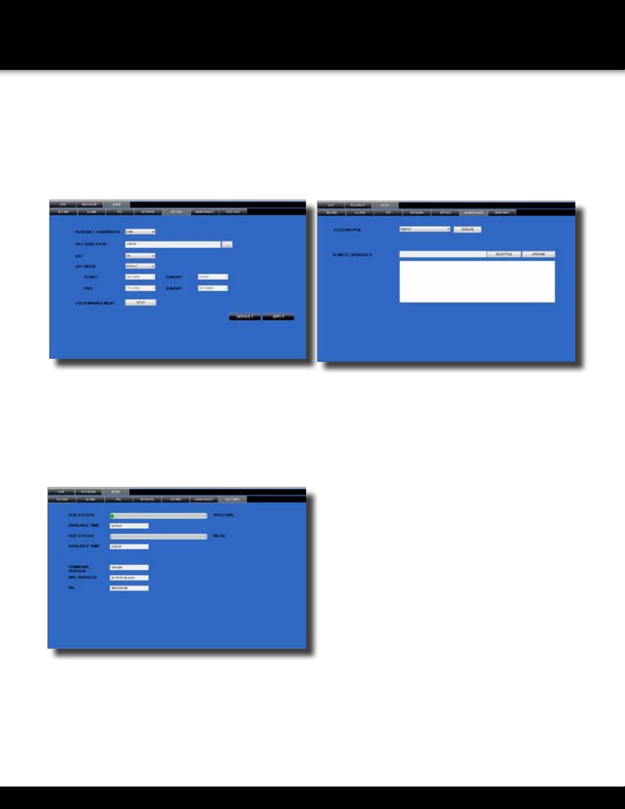
Setting, Maintenance and Host Info Tabs38
8Mobile Phone39
Mobile Setup39-40
9
Appendix41
Hard Drive Removal and Installation41
Specifications42
Notes43
FAQ’s (Frequently Asked Questions)44-45
Troubleshooting46
Warranty47
Page 6
SAFETY
CAUTION STATEMENTS
Safety Precautions
•Do not drop, puncture, or disassemble the cameras or DVR.
•Do not tug on the power adapter. Use the plug to remove it from the wall.
•Do not expose the cameras or DVR to high temperatures.
•For your own safety, avoid using the DVR when there is a storm or lightning in your area.
•Use the cameras and DVR with care. Avoid pressing hard on the cameras or DVR body.
•Do not use power cable if it is damaged or crushed.
FCC Compliance Class B Digital Device
This equipment has been tested and found to comply with the limits for a Class B digital device, pursuant to Part 15 of the FCC rules. These limits are
designed to provide reasonable protection against harmful interference in a residential installation. This equipment generates, uses and can radiate
radio frequency energy and, if not installed and used in accordance with the instructions, may cause harmful interference to radio communications.
However, there is no guarantee that the interference will not occur in a particular installation. If this equipment does
cause harmful interference to radio or television reception, which can be determined by turning the equipment off and
on, the user is encouraged to try to correct the interference by one or more of the following measures:
•Reorient or relocate the receiving antenna.
•Increase the separation between the equipment and receiver.
•Connect the equipment into an outlet on a circuit different from that of the receiver.
•Consult the dealer or an experienced radio or TV technician for help.
Notice: Only peripherals complying with FCC class B limits may be attached to this equipment. Operation with non-compliant peripherals
or peripherals not recommended by First Alert / BRK Brands, Inc. is likely to result in interference to radio and TV reception. Changes or
modications to the product, not expressly approved by First Alert / BRK Brands, Inc., could void the user’s authority to operate the equipment.
Important: The information shown in the FCC Declaration of Conformity paragraph below is a requirement of the FCC and
is intended to supply you with information regarding the FCC approval of this device. The phone number listed below is for
FCC related questions only and not intended for questions regarding the connection or operation for this device.
FCC Declaration of Conformity for devices with the FCC logo. Responsible Party: First Alert / BRK Brands, Inc., 3901
Liberty Street Rd., Aurora, IL. 60504-8122. Telephone: (630) 851 - 7330. Product / Model: DVR0805 and DVR0810.
We, First Alert / BRK Brands, Inc. declare under our sole responsibility that the device to which this declaration relates: Complies with
Part 15 of the FCC Rules. Operation is subject to the following two conditions: (1) this device may not cause harmful interference,
and (2) this device must accept any interference received, including interference that may cause undesired operation.
FCC Certification (if applicable)
This device contains a radio transmitter. Accordingly, it has been certied as compliant with 47 CFR Part 15 of the
FCC Rules for intentional radiators. Products that contain a radio transmitter are labeled with an FCC ID.
FCC Compliance
These symbols indicate that it is prohibited to
dispose of these batteries in the household
waste. Take spent batteries that can no longer
be charged to the designated collection points
in your community.
Disposal
fire and electric shock hazard statement
Caution!
When working with electrostatic sensitive de-
vices such as hard disk or DVR unit, make sure
you use a static-free workstation. Any electro-
static energy coming in contact with the hard
disk or DVR can damage it permanently.
CAUTION: TO REDUCE THE RISK OF ELECTRIC SHOCK.
UNPLUG ALL POWER SOURCES, INCLUDING CAMERAS FROM
THE DVR BEFORE REMOVING COVER. FAILURE TO DO SO CAN
RESULT IN DAMAGE TO THE DVR OR ITS COMPONENTS AS
WELL AS INJURY OR DEATH.
The lightning ash with arrowhead symbol, within an equilateral
triangle, is intended to alert the user to the presence of un-insulated
“dangerous voltage” within the product’s enclosure that may be of
sufcient magnitude to constitute a risk of electric shock.
The exclamation point within an equilateral triangle, is intended to
alert the user to the presence of important operating and maintenance
(servicing) instructions in the literature accompanying the appliance.
WARNING: TO PREVENT FIRE OR SHOCK HAZARD, DO NOT
EXPOSE THIS DVR UNIT TO RAIN OR MOISTURE
CAUTION: TO PREVENT ELECTRIC SHOCK, MATCH WIDE
BLADE OF THE PLUG TO THE WIDE SLOT AND FULLY INSERT
CAUTION
RISK OF ELECTRIC SHOCK
Page 7
PRODUCT OVERVIEW
PACKAGE CONTENTS
What,s in the Box*
H.264 8 channel Digital DVR
with 500 GB or 1 TB Hard Drive
DC8405: 500 GB
DC8810: 1 TB
USB 2.0 Mouse
WARNING
PROTECTED BY
THESE PREMISES ARE UNDER
24 HOUR VIDEO SURVEILLANCE
3 Window
Warning Decals
Installation
Software
Power Supply for
DVR and Cameras
RJ45 Ethernet Cable
9-way Power splitter -
8 cameras, 1 DVR
Quick Install Guide
Remote Control
BNC Video & DC Power Cable
DC8405: 4 cables
DC8810: 8 cables
*If purchased with cameras.
mobile phone/
web ready
night vision
advanced video
compression
USER’S MANUAL
Model
DC8405-420 8 Channels/4 Cameras
DC8810-420 8 Channels/8 CamerasDVR
500GB
indoor/outdoor
420 TVL cameras
digital dvr
recorder
DVR
Page 8
PRODUCT OVERVIEW
DVR CONTROLS
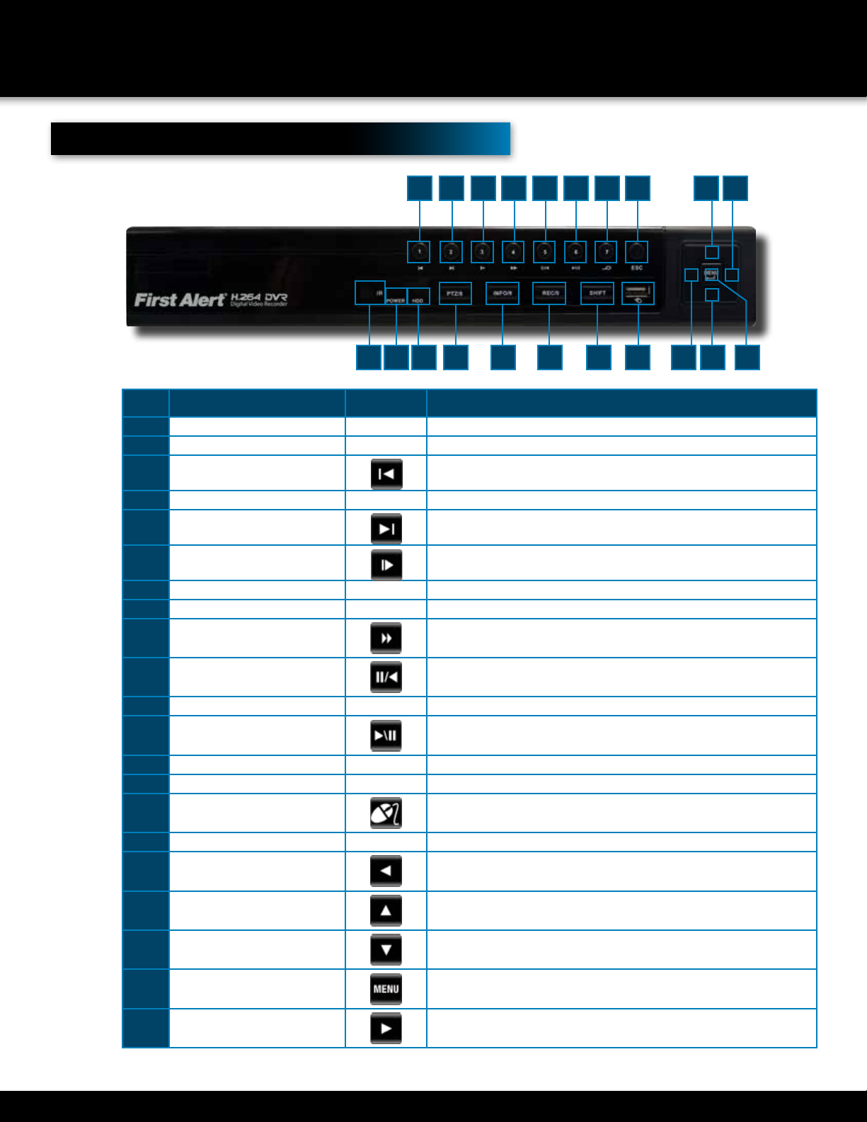
Front Panel
itemFunctioncontrolDeScription
1(1) IR remote receiver Direct remote towards this position when using DVR
2Power indicator light A red light indicates power is on
3Previous file/1 In Live Mode shows camera One; In search and Playback mode: selects
previous file in list;Use to select previous entry in a list
4HDD indicator lightGreen light indicates hard drive is available.
5Next file /2 In Live Mode shows camera One; In search and Playback mode: selects
next file in list;Use to select next entry in a list
6PTZ /8 In Live Mode shows camera Eight;Press shift the PTZ will bring PTZ
menu up
7Slow play /3 In Live Mode shows camera One; Plays video at slow speed
8HDD Info/9Brings up hard drive information screen
9Fast play/4 Plays video at fast speed
10Backward pause/5 Play or Pause video in backward mode
11Record /0 Brings the Record Mode menu up
12Play Pause /6Play or Pause video in forward mode
13ShiftPress Shift and Release to select alternate functions
14Search video/7 Brings up the Search/Playback screen
15USB Connection for mouse
16ESCBrings system previous selection
17Left In menu mode: moves to highlight next section
18Up In live mode: rotates between single , quad, eight or nine camera screen
19Down In live mode: rotates between single , quad, eight or nine camera screen
20Menu/Enter Press to make selection
21RightIn menu mode: moves to highlight previous section
12
3579101214161821
468111315171920
Page 9
PRODUCT OVERVIEW
DVR CONTROLS
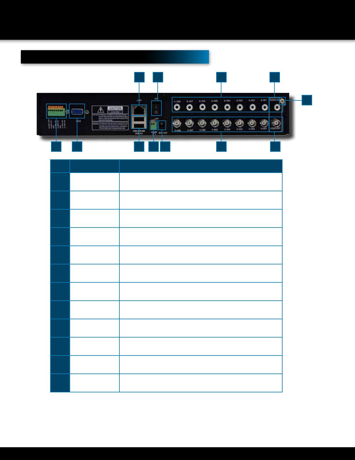
Back Panel
itemFunctionDeScription
1 Alarm 4 alarm inputs
2 VGA Output For connecting to VGA monitor
3 USB/Mouse Use Upper USB port for mouse connection; Use Lower USB port for USB
flashdrive or backup
4LanFor connecting RJ45 ethernet cable to PC or router
5 RS485 For connecting PTZ cameras
6 Power Switch Power On/Off
7 Power Supply For connection to power cord +12V DC
8 Audio Input For connecting audio signal from audio capable cameras or self powered
microphones (RCA jacks)
9 Video Input For connecting video signal from cameras (BNC)
10 Audio Output For connecting audio signal to amplified speakers (RCA jacks)
11 BNC Output For connecting to a BNC monitor
12GroundGround Connection
12357911
46810
12
Page 10
Remote Control
Remote Control Operation
The remote control is the secondary input device for navigating the system’s interface.
In device operation, the MENU key has the same function as “left click” of the mouse.
PRODUCT OVERVIEW
REMOTE CONTROL
7
2
1
6
5
4
3
8
9
Directions for Installing/
Changing Batteries
1. Open battery compartment on back of
Remote and insert (2) Alkaline
AAA batteries (provided.)
2. Ensure all batteries are installed correctly
with regard to polarity (+ and -.)
3. Remove batteries from Remote if it is not
to be used for an extended period of time.
4. Remove used batteries promptly and replace
all batteries of a set at the same time.
5. Always purchase the correct size and grade
of battery most suitable for intended use.
itemFunctionDeScription
1Multi Rotates between single, quad, eight or nine camera view
2Numeric
Buttons
Press to Select channel to view; use to input numerical information in
appropriate screens
3EscMove back to previous menu screen
4
NAvigAtioN BUttoNS
Menu
Brings up menu options: In menus, press to confirm selections; in
PTZ mode, press to change the navigation buttons to control the con-
nected PTZ camera (not included)
Press to move cursor up; in PTZ mode, press to pan camera up
Press to move cursor down; in PTZ mode, press to pan camera down
Press to move cursor left; in PTZ mode, press to pan camera left
Press to move cursor right; in PTZ mode, press to pan camera right
5
PLAYBACK CoNtRoLS
Move to previous record for viewing
Move to next record for viewing
Press to fast forward 2X,4X,8X, 16X,Normal
Press once to Pause, then reverse by frame, reverse normal speed,
reverse 2X,4X,8X, back to pause
Press once pause, twice to move forward
Playback frame by frame in forward and reverse
6Record ModePress to bring RECORD Menu on screen
7ADDUse when controlling multiple DVR systems
8FNUse when imputting information, Press FN to step through upper
case, lower case and numbers
9SEARChUse to Search recorded video files
Page 11
PRODUCT OVERVIEW
MOUSE AND VIRTUAL KEYPAD
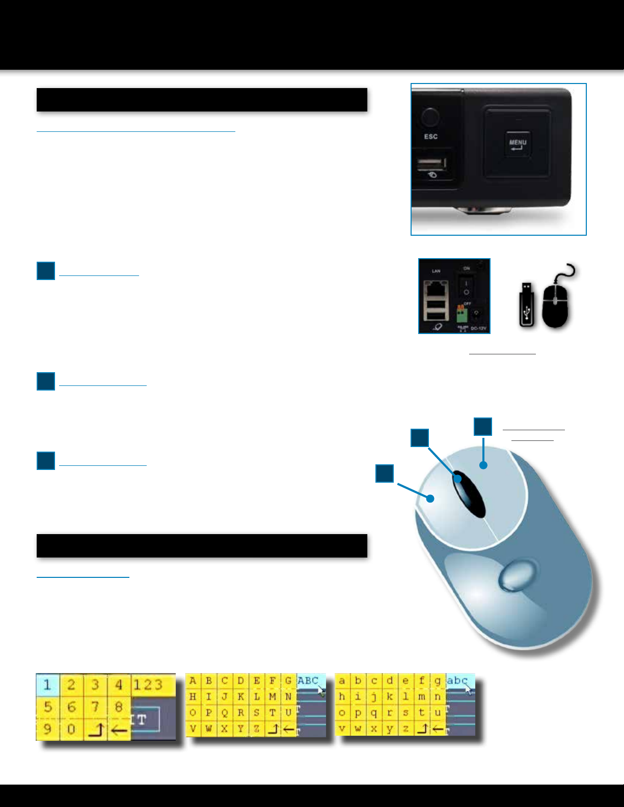
Mouse Operation with this DVR
The mouse is the primary input device for navigating system menus.
NOTE: Unless otherwise noted, all system functions described
in this manual are achieved through mouse input.
To use a mouse with the system:
Connect a USB mouse to the USB MOUSE port on front panel of the system.
NOTE: Only the USB 2.0 port on the back panel (bottom USB
port) is designed for data backup to a USB flash drive. Do not
connect a USB flash drive to the USB MOUSE port.
Use the mouse buttons to perform the following:
1Left-Button:
•Click to select a menu option
•During live viewing in split-screen double-click on a chan-
nel to view the selected channel in full-screen
•Double-click the channel again to return to split-screen view
•Selecting letter or number on the virtual keypad
2Right-Button:
•Click to open the Quick Access Menu
•Exits any window
•Exits any menu or re-opens previous menu
3Scroll-Wheel:
•Use scroll wheel to step through full screen views of the cameras
Mouse Controls
DVR Front Face
Connect Mouse &
USB Drive
2
1
Mouse Button
Operation
3
Virtual Keypad
Virtual Keypad
To enter text or numerical data, the system uses a virtual keypad. In fields
where letters or numbers can be entered, you can switch between various
formats – numbers, upper case (ABC) and lower case (abc). Note you can
access all numbers when in the “Letters” virtual keypads. See below.
NumbersLetters-UppercaseLetters-Lowercase
Page 12
Installing Cameras
Mounting Cameras and Running Cable
Select the position for the camera and secure the camera stand. Screw the camera onto the stand. Adjust camera to the proper
view angle. Make sure the lens is upright relative to the subject. Tighten the thumb bolt. First Alert cameras can be either ceiling
or wall mounted by simply reversing the camera stand mounting. See “Camera Orientation” Info box. Holes are provided on
both the top and bottom of the camera housing to accommodate most mounting requirements. Run cable from camera to DVR
location. See Information box below on “Longer Cable Runs”.
Camera Orientation
It’s important the camera is mounted correctly to
ensure the image is not upside down as the cam-
era lens can only be positioned one way.
Longer Cable Runs
Longer cable runs may require an upgrade to
RG59 Coax cable. First Alert kits ship with eco-
nomical AV cable that is designed to work well up
to the length of cable provided, usually around
60 feet. If longer distances between camera and
DVR are required, you will need to upgrade to RG59 Coax cable. We
provide several lengths up to 300 feet. In addition, if you need to run
cable for in-wall installations, then you may require fire rated cable,
FT-4/CMR UL approved for in-wall installations.
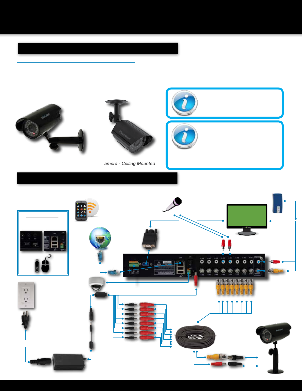
Camera - Wall MountedCamera - Ceiling Mounted
PRODUCT OVERVIEW
CAMERA AND POWER CONNECTIONS
Step 2... Connecting Devices
Splitter -
8 camera/
1 PowerVideo to DVR
Channels 1-8
Video to Camera
Power to Camera
Power to DVR
Power to Cameras
Power
from 120V
DC Converter - 12V
AV Cable: BNC/
DC Power
(1 per Camera)
VGA to PC Monitor or TV
BNC to Security Camera Monitor
(Not included)
RJ45 Ethernet
to Router and
Internet
PTZ & Alarm Connections
(Cameras not included)
Follow this diagram to make device connections. Note, some devices are not
included with this kit. See “What’s in the Box” for included devices.
Front & Back Panels
Connect Mouse &
USB Drive
RCA Audio In from Audio
Cameras or Powered
Microphone
(Not included)
RCA Audio Out to
Powered Speakers
(Not included)
Smartphone
through Mobile
Internet Setup
(Smartphone Not
included)
Page 13
System Start Up
Power On/Off
To power the system On/Off, connect the power
cable to the DC 12V port on the rear panel. Flip
the toggle switch on in the back of the DVR. At
startup, the system performs a basic system check
and runs an initial loading sequence. After a few
moments, the system loads a live display view.
INITIAL SETUP
SYSTEM OPERATION
Quick Access Menu
When using the mouse, use the Quick Access Menu
to access several system options, including the
Main Menu. Select one of the following options:
•MAIN MENU: Opens the main system menu
•Record Mode: Allows the user to select the
record setting for any or all channels.
•Search: Open the Search Menu
to view recorded video
•PTZ Control: Opens the PTZ control menu
•Start Tour: Allows user to start touring
the cameras in sequence.
•Volume Regulate: Allows volume adjust during
playback mode or when monitoring.
•Logout: Provides options to Logout,
Shutdown or to reboot system.
•View 1: Allows viewing of one camera in full screen.
•View 4: Allows viewing of 4 cameras on screen.
•View 8: Allows viewing of 8 cameras on
screen, with one screen in larger view.
•View 9: Allows viewing of 8 cameras on screen.
•To close the Sub-Menu, click anywhere on-screen.
User Login
Password
ATTENTION: By default, passwords are disabled on
the system. You do not need to enter a password
when accessing any system menus. However, for
security purposes, it is highly recommended to
enable passwords on the system using the Password
Menu. See “Password” section for details on setting
up passwords. Click OK to confirm password.
Main Viewing Screen
User Login Menu
Power Switch
ViDeo iconSFunction
Indicates the channel is recording.
Video is unavailable on the channel
Camera speaker icon stays visible on screen
Motion is detected on the channel
Indicates that the monitor is touring
camera channels
Indicates audio output is from this channel
Page 14
Password Setup
Setting Up Passwords & User Permissions
When you first startup your DVR, you are automatically logged
in as the ADMIN. By default, passwords are disabled
on the system. You will not need a password to log in
or access menus. You will not need a password to access
your system using the browser-based remote software.
Click ok to access this menu.
The system employs three levels of user
authorities. The levels are as follows:
•ADMIN (administrator): Has full control of the system, and can
change both administrator and user passwords and enable/disable
password checking and can add or delete user authorities.
•DEFAULT USER (normal user): Only has access to live
viewing, search, playback, and other limited authorities.
•GUEST: Only has access to live viewing, search,
playback, and other limited authorities.
For security reasons, it is highly recommended to enable passwords on
your system. If you enable passwords, select a 6-digit USER password.
The ADMIN and USER passwords must not be the same. If you forgot your
password, please contact First Alert Consumer Affairs @ 1-800-323-9005
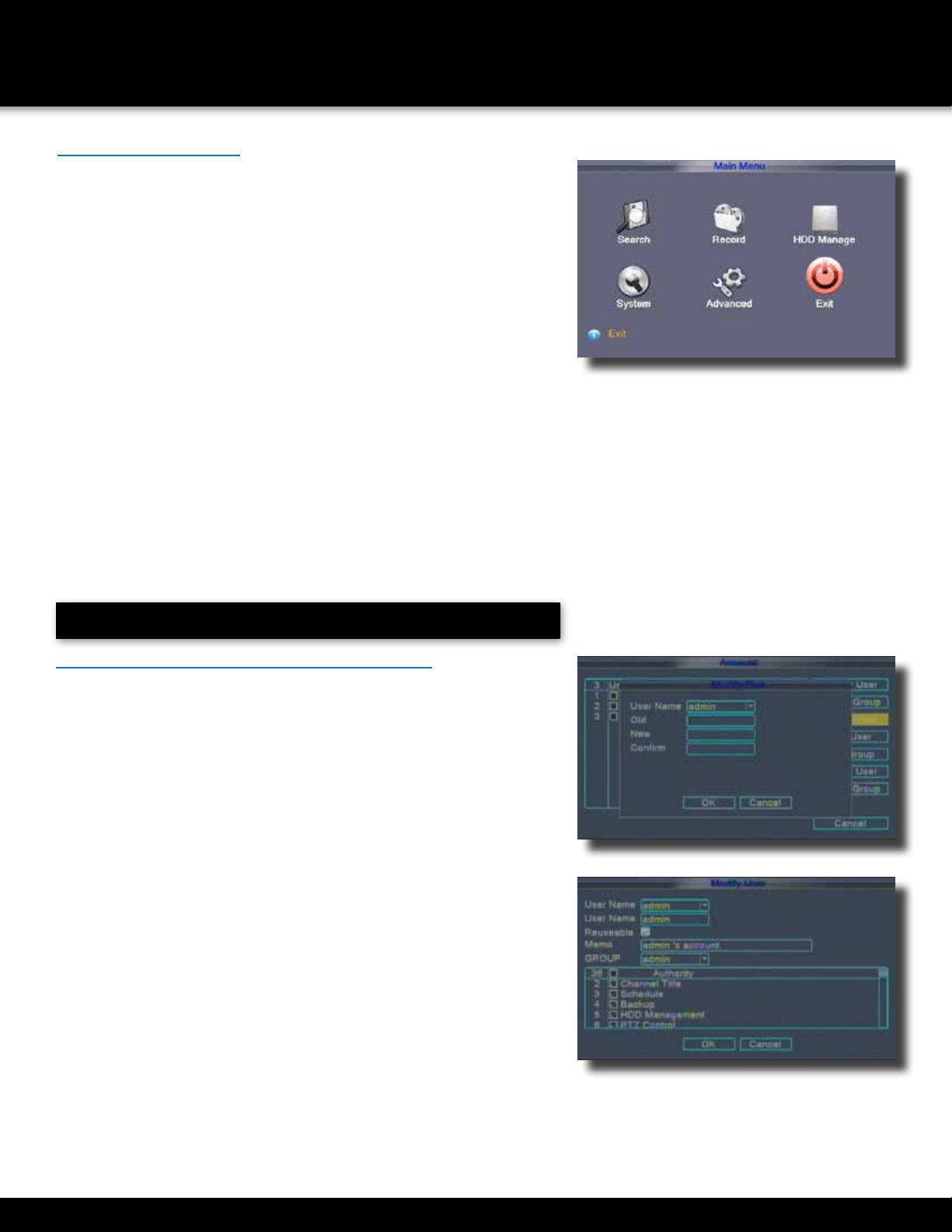
Main Menu Access
To open the Main Menu: Right-click anywhere on-screen to open the
Quick Access Menu and select MAIN MENU (mouse only), or press
the MENU button on the remote control or front panel of the system.
NOTE: If passwords are enabled on the system, enter the
6-digit numerical password to open the Main Menu.
Main Menu
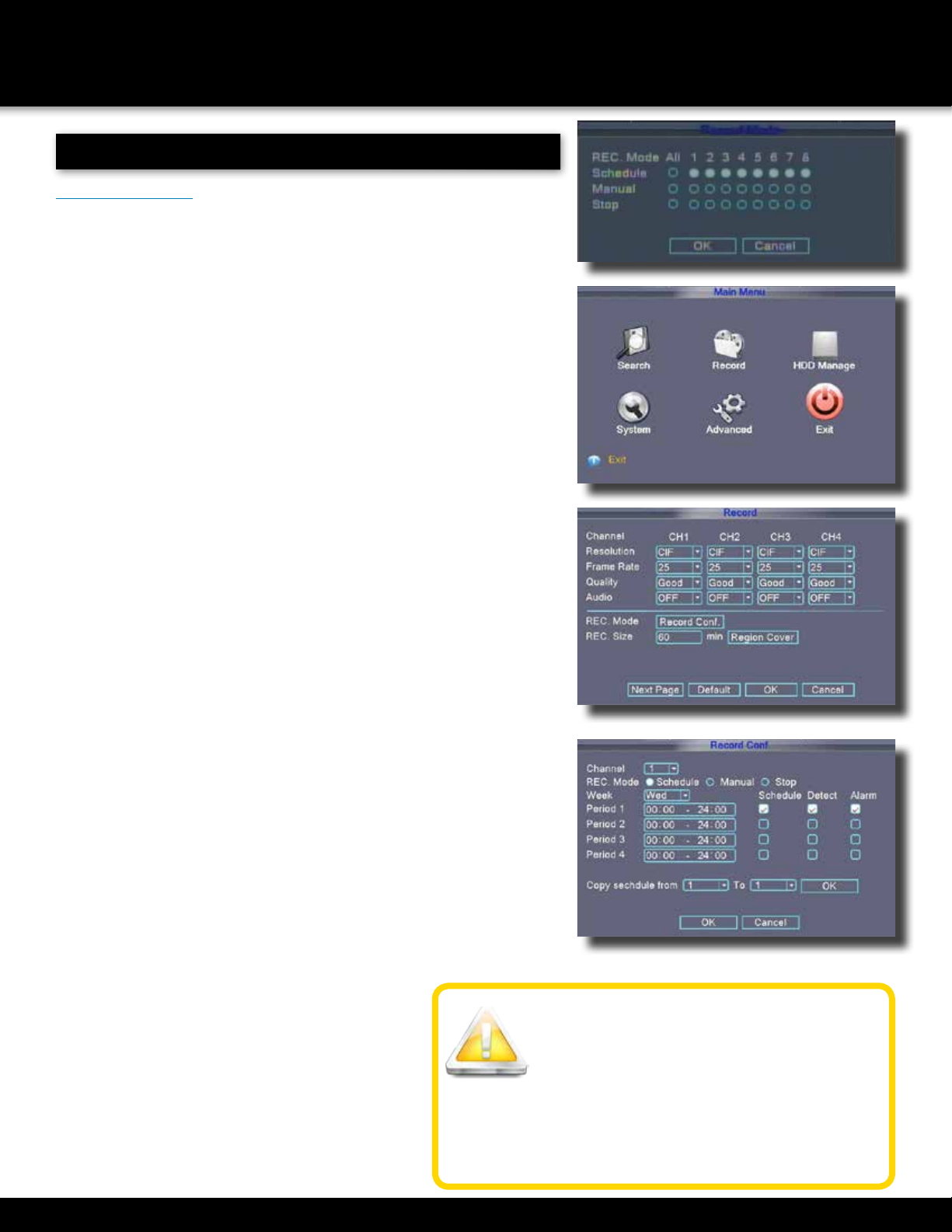
1. RECORD SEARCH: Search for recorded video on the system.
2. RECORD: Configure recording parameters (quality, resolution), set
record modes, and enable/disable audio recording. Note: Audio capable
cameras (not included) are required for audio recording on the system.
3. HDD MANAGE: Display hard drive status and format
the internal hard drive of the sys tem.
4. SYSTEM: Open the Basic Setup Menu, which lets you
set the system language, date and time, passwords,
and configure display, audio and video settings.
5. ADVANCED: Opens the Advanced Setup Menu, which
lets you set mail options, Alarm settings, look up system
version information, motion detect, enable mobile monitor,
AutoMaintain, configure PTZ, set network settings.
6. EXIT: Closes the Main Menu.
INITIAL SETUP
SYSTEM OPERATION
Modify Password
Modify Account
Main Menu
Page 15
INITIAL SETUP
SYSTEM OPERATION
Add Group
Add User
Account Modify
To Set Password
Click on Main Menu, System, and Account to
reach the Account Configuration Screen.
Click on MODIFY PASSWORD
Select the user name
Using the virtual mouse, input the Old (existing)
PASSWORD, NEW password.
Click OK to confirm. The system will confirm the change.
Click OK to exit.
Only the ADMIN can ADD or MODIFY a GROUP or USER.
USER can modify their password only.
To ADD a Group or USER
Click on Main Menu, System, and Account to
reach the Account Configuration Screen.
Click on ADD GROUP or ADD USER
Select the GROUP or USER name
Using the virtual mouse, to input the name of the group or user.
In the Authority section, choose the specific allowable
actions that you want this group or user to have access
to by clicking the appropriate check box.
Click OK to confirm.
The system will confirm the change.
Click OK to exit.
To Modify the Group or User
Click on Main Menu, System, and Account to
reach the Account Configuration Screen.
Click on MODIFY GROUP or MODIFY USER
Select the GROUP or USER using the drop down menu.
In the Authority section, choose the specific allowable
actions that you want this group or user to have access
to by clicking the appropriate check box.
Click OK to confirm.
The system will confirm the change.
Click OK to exit.
There is no limit in the user and user group. You can add or delete the user
Libble takes abuse of its services very seriously. We're committed to dealing with such abuse according to the laws in your country of residence. When you submit a report, we'll investigate it and take the appropriate action. We'll get back to you only if we require additional details or have more information to share.
Product:
Forumrules
To achieve meaningful questions, we apply the following rules:
First, read the manual;
Check if your question has been asked previously;
Try to ask your question as clearly as possible;
Did you already try to solve the problem? Please mention this;
Is your problem solved by a visitor then let him/her know in this forum;
To give a response to a question or answer, do not use this form but click on the button 'reply to this question';
Your question will be posted here and emailed to our subscribers. Therefore, avoid filling in personal details.
Register
Register getting emails for First Alert DVR0805 at:
new questions and answers
new manuals
You will receive an email to register for one or both of the options.
Get your user manual by e-mail
Enter your email address to receive the manual of First Alert DVR0805 in the language / languages: English as an attachment in your email.
The manual is 3.38 mb in size.
You will receive the manual in your email within minutes. If you have not received an email, then probably have entered the wrong email address or your mailbox is too full. In addition, it may be that your ISP may have a maximum size for emails to receive.
The manual is sent by email. Check your email
If you have not received an email with the manual within fifteen minutes, it may be that you have a entered a wrong email address or that your ISP has set a maximum size to receive email that is smaller than the size of the manual.
The email address you have provided is not correct.
Please check the email address and correct it.
Your question is posted on this page
Would you like to receive an email when new answers and questions are posted? Please enter your email address.