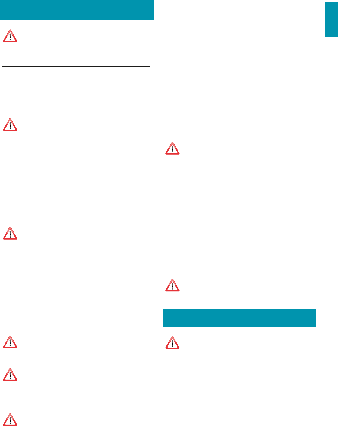
PL - FILTRY Z WĘGLEM AKTYWNYM/HP (opcjonalne) : Montaż
NL - ACTIVE KOOLSTOFFILTERS/HP (optie) : Montage
PT - FILTROS DE CARVÃO ATIVADO/HP (opcionais) : Montagem
DK - AKTIVE KULFILTRE/HP (Tilvalg) : Montage
SE - AKTIVA KOLFILTER/HP (tillval) : Montage
FI - AKTIIVIHIILISUODATTIMET/HP (lisävarusteita) : asennus
NO - FILTER MED AKTIVT KULL/HP (tilvalg) : Montering
PLANE
22
2324
22
IT - FILTRI AL CARBONE ATTIVO/HP (opzionali) :
montaggio
EN - HP/ACTIVE CARBON FILTERS (optional):
assembling
DE - AKTIVKOHLEFILTER/HP (optional): Montage
FR - FILTRES AU CHARBON ACTIF/HP (en option) :
Montage
ES - FILTROS DE CARBÓN ACTIVO/HP (opcionales) :
Montaje
RU - / (-
) :
PL - FILTRY Z WĘGLEM AKTYWNYM/HP (opcjonalne) :
Montaż
NL - ACTIVE KOOLSTOFFILTERS/HP (optie) : Montage
PT - FILTROS DE CARVÃO ATIVADO/HP (opcionais) :
Montagem
DK - AKTIVE KULFILTRE/HP (Tilvalg) : Montage
SE - AKTIVA KOLFILTER/HP (tillval) : Montage
FI - AKTIIVIHIILISUODATTIMET/HP (lisävarusteita) :
asennus
NO - FILTER MED AKTIVT KULL/HP (tilvalg) : Montering
1
2
1
2
25
26
23
ITALIANO
ISTRUZIONI DI SICUREZZA
E AVVERTENZE
Il lavoro d’installazione deve essere eseguito da installatori competenti e
qualicati, secondo quanto indicato nel presente libretto e rispettando le
norme in vigore.
Se il cavo di alimentazione o altri componenti sono danneggiati, la cappa NON deve
essere utilizzata: staccare la cappa dall'alimentazione elettrica e contattare il Rivenditore o
un Centro Assistenza Tecnica autorizzato per la riparazione.
Non modicare la struttura elettrica, meccanica e funzionale dell'apparecchiatura.
Non tentare di eettuare da soli riparazioni o sostituzioni: gli interventi eettuati da
persone non competenti e qualicate possono provocare danni, anche molto gravi, a
cose e/o persone non coperti da garanzia del Costruttore.
AVVERTENZE PER L'INSTALLATORE
SICUREZZA TECNICA
Prima di installare la cappa controllare l'integrità e funzionalità di ogni sua
parte: se si notano anomalie non procedere nell'installazione e contattare
il Rivenditore.
Nel caso sia stato riscontrato un difetto estetico la cappa NON deve essere installata;
riporla nel suo imballo originale e contattare il Rivenditore.
Una volta installata non sarà accettato alcun reclamo per difetti estetici.
Durante l'installazione utilizzare sempre mezzi di protezione personale (es.: scarpe antiinfor-
tunistiche) ed adottare comportamenti prudenti e corretti.
Il kit di fissaggio (viti e tasselli) fornito con la cappa è utilizzabile unicamente su pareti in mu-
ratura: in caso di installazione su pareti di materiale diverso, valutare altri sistemi di fissaggio
tenendo conto della resistenza del muro e del peso della cappa (indicato a pag. 2).
Tenere presente che l’installazione con sistemi di fissaggio diversi da quelli forniti o non
conformi può comportare rischi di natura elettrica e di tenuta meccanica.
Non installare la cappa in ambienti esterni e non esporla ad agenti atmosferici (pioggia,
vento, ecc...).
SICUREZZA ELETTRICA
L’impianto elettrico al quale viene collegata la cappa deve essere a norma
e munito di collegamento a terra secondo le norme di sicurezza del Paese
di utilizzo; deve essere inoltre conforme alle normative Europee sull’anti-
disturbo radio.
Prima di installare la cappa verificare che la tensione di rete corrisponda a quella riportata
dalla targhetta posta all’interno della cappa.
La presa usata per il collegamento elettrico deve essere facilmente raggiungibile con l’ap-
parecchiatura installata: in caso contrario, prevedere un interruttore generale per disconnet-
tere la cappa al bisogno.
Ogni eventuale modifica all’impianto elettrico dovrà essere eseguita solo da un elettricista
qualificato.
La lunghezza massima della vite di fissaggio del camino (fornita dal fabbricante) è di 13
mm. L'utilizzo di viti non conformi con le presenti istruzioni può comportare rischi di natura
elettrica.
In caso di malfunzionamenti dell’apparecchio, non tentare di risolvere da soli il problema,
ma contattare il Rivenditore o un Centro di Assistenza autorizzato per la riparazione.
Durante l'installazione della cappa, disinserire l’apparecchio togliendo la
spina o agendo sull’interruttore generale.
SICUREZZA SCARICO FUMI
Non collegare l’apparecchio a condotti di scarico dei fumi prodotti dalla
combustione (ad es. caldaie, caminetti, ecc...)
Prima dell'installazione della cappa assicurarsi che siano rispettate tutte le normative vigenti
sullo scarico dell’aria all’esterno del locale.
AVVERTENZE PER L'UTILIZZATORE
Queste avvertenze sono state redatte per la vostra sicurezza e per quella
degli altri, Vi preghiamo, dunque, di leggere attentamente questo libretto
in tutte le sue parti prima di utilizzare l’apparecchio o di eettuare opera-
zioni di pulizia sullo stesso.
Il Costruttore declina ogni responsabilità per eventuali danni che possano, diretta-
mente o indirettamente, essere causati a persone, cose ed animali domestici con-
seguenti alla mancata osservanza delle avvertenze di sicurezza indicate in questo
libretto.
È molto importante che questo libretto istruzioni sia conservato insieme all’apparec-
chiatura per qualsiasi futura consultazione.
Se l’apparecchio dovesse essere venduto o trasferito ad un’altra persona, assicurarsi che an-
che il libretto venga fornito, in modo che il nuovo utente possa essere messo al corrente del
funzionamento della cappa e delle avvertenze relative.
Dopo l’installazione delle cappe in acciaio inox è necessario eseguire la pulizia della stessa
per rimuovere i residui di collante del protettivo e le eventuali macchie di grasso e oli, che,
se non rimosse, possono causare il deterioramento irreversibile della superficie della cappa.
Per questa operazione il costruttore raccomanda l’utilizzo delle salviette in dotazione, dispo-
nibili anche in acquisto
Esigere parti di ricambio originali.
DESTINAZIONE D'USO
L’apparecchio è destinato solo ed esclusivamente per l'aspirazione di fumi generati
dalla cottura di alimenti in ambito domestico, non professionale: qualsiasi utilizzo
diverso da questo è improprio, può provocare danni a persone, cose ed animali do-
mestici e solleva il Costruttore da qualsiasi responsabilità.
L’apparecchio può essere utilizzato da bambini di età non inferiore a 8 anni e da persone
con ridotte capacità fisiche, sensoriali o mentali, o prive di esperienza o della necessaria
conoscenza, purché sotto sorveglianza oppure dopo che le stesse abbiano ricevuto istru-
zioni relative all’uso sicuro dell’apparecchio e alla comprensione dei pericoli ad esso inerenti.
I bambini non devono giocare con l’apparecchio. La pulizia e la manutenzione a cura
dell’utilizzatore non deve essere effettuata da bambini senza sorveglianza.
AVVERTENZE PER L'UTILIZZO E LA PULIZIA
Prima di procedere a qualsiasi operazione di pulizia o di manutenzione,
disinserire l’apparecchio togliendo la spina o agendo sull’interruttore ge-
nerale.
Non utilizzare la cappa con le mani bagnate o piedi scalzi.
Quando l’apparecchio non viene usato, controllare sempre che tutte le parti elettriche, (luci,
aspiratore), siano spente.
Il peso massimo complessivo di eventuali oggetti posizionati o appesi (ove previsto) sulla
cappa non deve superare 1,5 Kg.
Controllare le friggitrici durante l’uso: I’olio surriscaldato potrebbe infiammarsi.
Non accendere fiamme libere sotto la cappa.
Non preparare cibi alla fiamma sotto la cappa.
Non utilizzare mai la cappa senza i filtri metallici antigrasso; grasso e sporco in questo caso si
depositerebbero nell'apparecchio compromettendone il funzionamento.
Parti accessibili della cappa possono essere calde se utilizzate insieme con apparecchi di
cottura.
Non effettuare operazioni di pulizia quando parti della cappa sono ancora calde.
Se la pulizia non è condotta secondo le modalità e i prodotti indicati nel presente libretto è
possibile un rischio di incendio.
Disinserire l’interruttore generale quando l’apparecchio non viene utilizzato per periodi pro-
lungati di tempo.
In caso di utilizzo contemporaneo di altre utenze (caldaie, stufe, caminetti,
ecc.) alimentate a gas o con altri combustibili, provvedere ad una adegua-
ta ventilazione del locale in cui avviene l’aspirazione dei fumi, secondo le
norme vigenti.
INSTALLAZIONE
parte riservata solo a personale qualicato
Prima di eettuare l'installazione della cappa, leggere attentamente il
cap. "ISTRUZIONI DI SICUREZZA E AVVERTENZE".
CARATTERISTICHE TECNICHE
I dati tecnici dell'apparecchio sono riportati su etichette posizionate all’interno della cappa.
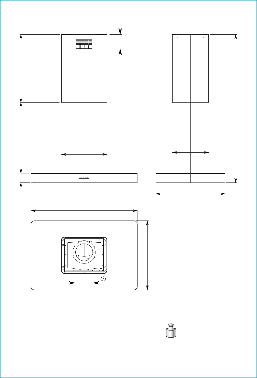
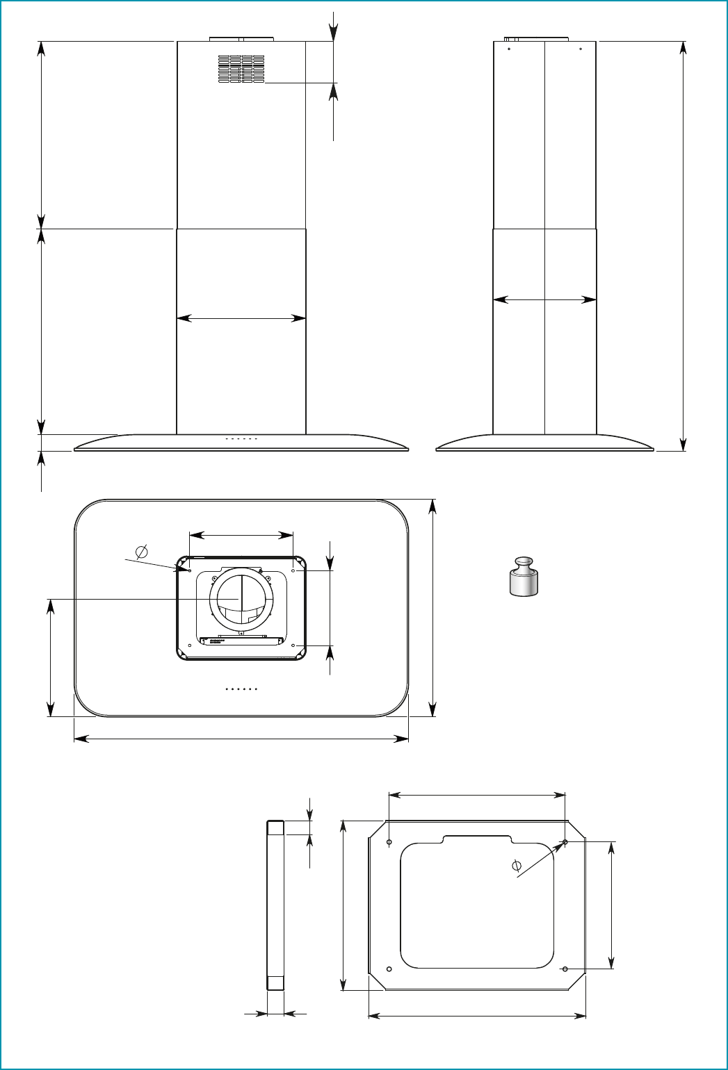
POSIZIONAMENTO
La distanza minima fra la parte più alta dell'apparecchiatura per la cottura e la parte
più bassa della cappa da cucina viene indicata nelle istruzioni di montaggio.
In generale, quando la cappa da cucina è posta su un piano cottura a gas, questa distan-
za deve essere almeno 65 cm (25,6"). Tuttavia sulla base di un’interpretazione della norma
EN60335-2-31 del 11-07-2002 da parte del TC61 (subclause 7.12.1 meeting 15 agenda item
10.11), la distanza minima tra piano cottura e parte inferiore della cappa può essere ridotta
alla quota riportata nelle istruzioni di montaggio.
Se le istruzioni del piano di cottura a gas specificano una distanza maggiore, bisogna te-
nerne conto.
Non installare la cappa in ambienti esterni e non esporla ad agenti atmosferici (pioggia,
vento, ecc...).
24
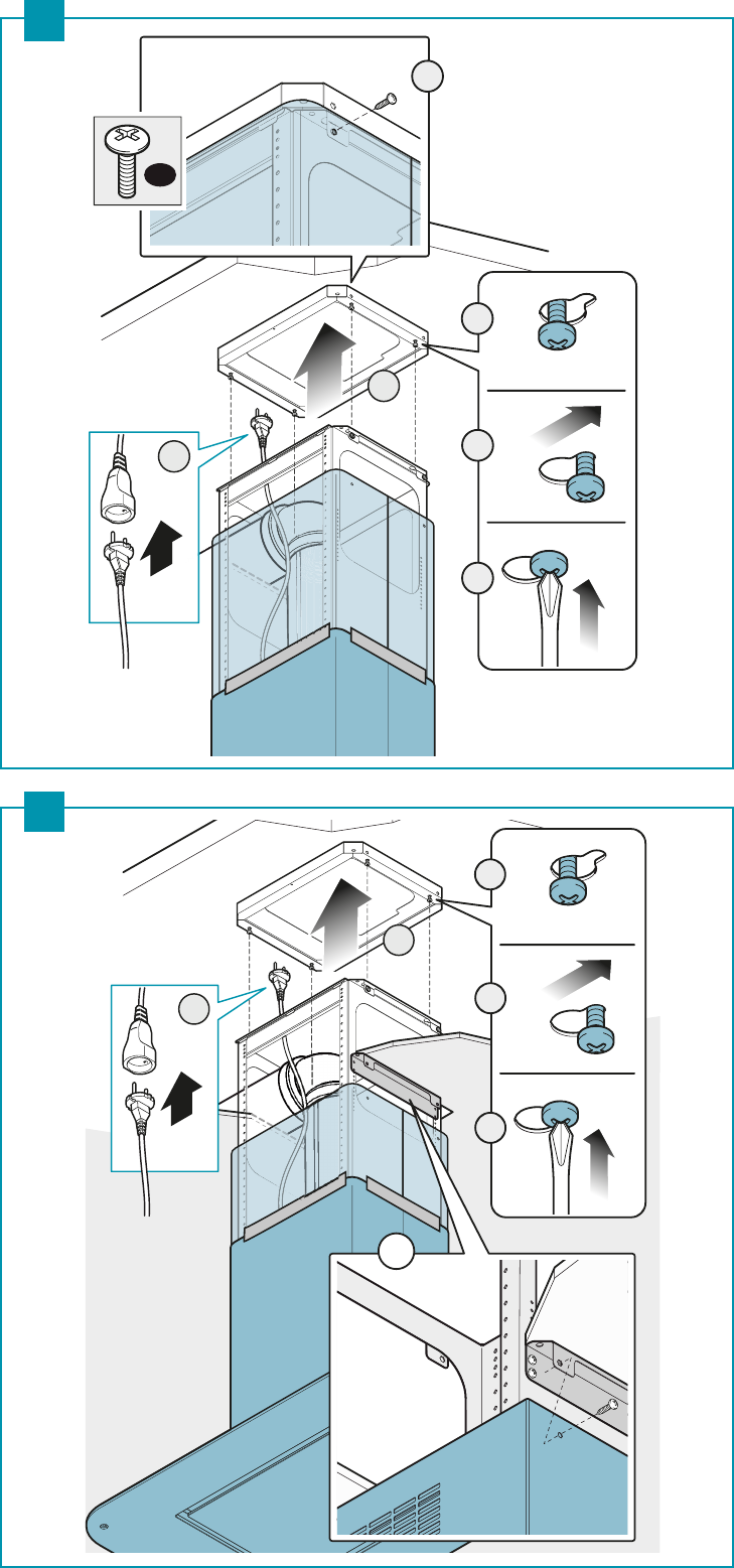
COLLEGAMENTO ELETTRICO
(parte riservata solo a personale qualicato)
Prima di eettuare qualsiasi operazione sulla cappa scollegare l’apparec-
chio dalla rete elettrica.
Assicurarsi che non vengano scollegati o tagliati li elettrici all’interno della
cappa:
in caso contrario contattare il Centro Assistenza più vicino.
Per l’allacciamento elettrico rivolgersi a personale qualicato.
Il collegamento deve essere eseguito in conformità con le disposizioni di legge in
vigore.
Prima di collegare la cappa alla rete elettrica, controllare che:
• la tensione di rete corrisponda a quella riportata sui dati di targa posti all’interno della
cappa;
• l’impianto elettrico sia a norma e possa sopportare il carico (vedi caratteristiche tecniche
posizionate all’interno della cappa);
• la spina e il cavo, di alimentazione, non devono entrare in contatto con temperature
superiori a 70 °C;
• l’impianto di alimentazione sia munito di efficace e corretto collegamento di terra se-
condo le norme vigenti;
•
la presa usata per il collegamento sia facilmente raggiungibile una volta installata la cappa.
In caso di :
• apparecchi dotati di cavo senza spina: la spina da utilizzare deve essere di tipo “normaliz-
zato”. Il fili devono essere collegati come segue: giallo-verde per la messa a terra, blu per
il neutro e il filo marrone per la fase. La spina deve essere collegata ad un'adeguata presa
di sicurezza.
•
apparecchio fisso non provvisto di cavo di alimentazione e di spina, o di altro dispositivo
che assicuri la disconnessione dalla rete, con una distanza di apertura dei contatti che
consenta la disconnessione completa nelle condizioni della categoria di sovratensione III.
Tali dispositivi di disconnessione devono essere previsti nella rete di alimentazione con-
formemente alle regole di installazione.
Il cavo di terra giallo/verde non deve essere interrotto dall’interruttore.
Il Costruttore declina ogni responsabilità nel caso le norme di sicurezza non vengano ri-
spettate.
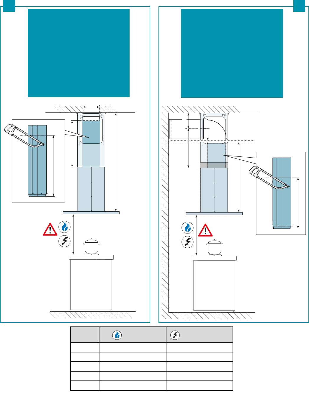
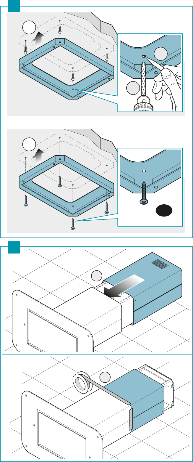
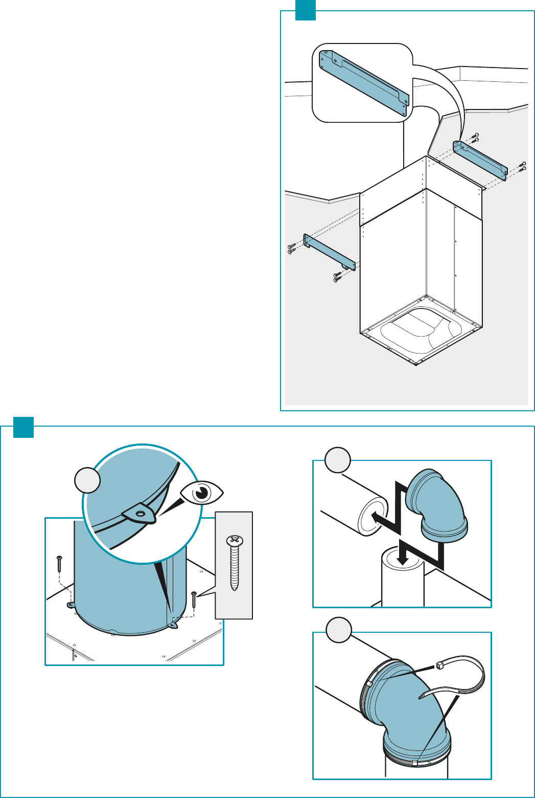
SCARICO FUMI
CAPPA AD EVACUAZIONE ESTERNA ASPIRANTE
In questa versione, fumi e vapori vengono convogliati verso l'esterno
attraverso il tubo di scarico.
A tal fine, il raccordo d'uscita della cappa, deve essere collegato tramite
un tubo, ad un'uscita esterna.
Il tubo d'uscita deve avere:
• un diametro non inferiore a quello di raccordo della cappa.
• una leggera inclinazione verso il basso (caduta) nei tratti orizzontali per evitare che la
condensa refluisca nel motore.
• il numero minimo indispensabile di curve.
• la lunghezza minima indispensabile per evitare vibrazioni e di ridurre la capacità aspiran-
te della cappa.
E' necessario isolare la tubazione se passa attraverso ambienti freddi.
Per impedire ritorni d'aria dall'esterno, una valvola di non ritorno è presente in presenza
di motori con 800m
3
/h o superiori.
Deviazione per la Germania:
quando la cappa da cucina e apparecchi alimentati con energia diversa da quella elettrica sono
in funzione simultaneamente, la pressione negativa nel locale non deve superare i 4 Pa (4 x 10⁻⁵
bar).
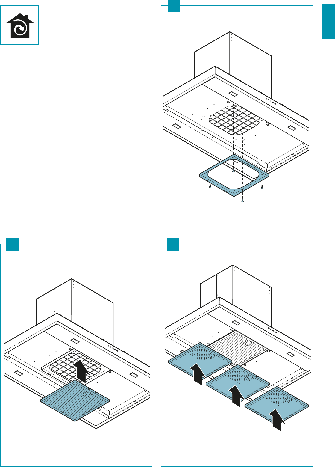
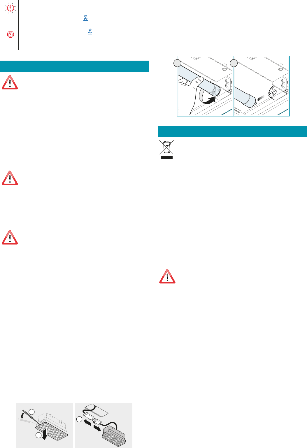
CAPPA A RICICLO INTERNO FILTRANTE
In questa versione l’aria passa attraverso i filtri al carbone attivo HP (op-
zionali) per essere purificata e riciclata nell’ambiente.
Controllare che i filtri al carbone attivo HP siano montati sulla cappa, in
caso negativo applicarli come indicato nelle istruzioni di montaggio.
In questa versione valvola di non ritorno non deve essere montata: rimuoverla se
presente sul raccordo di uscita aria del motore.
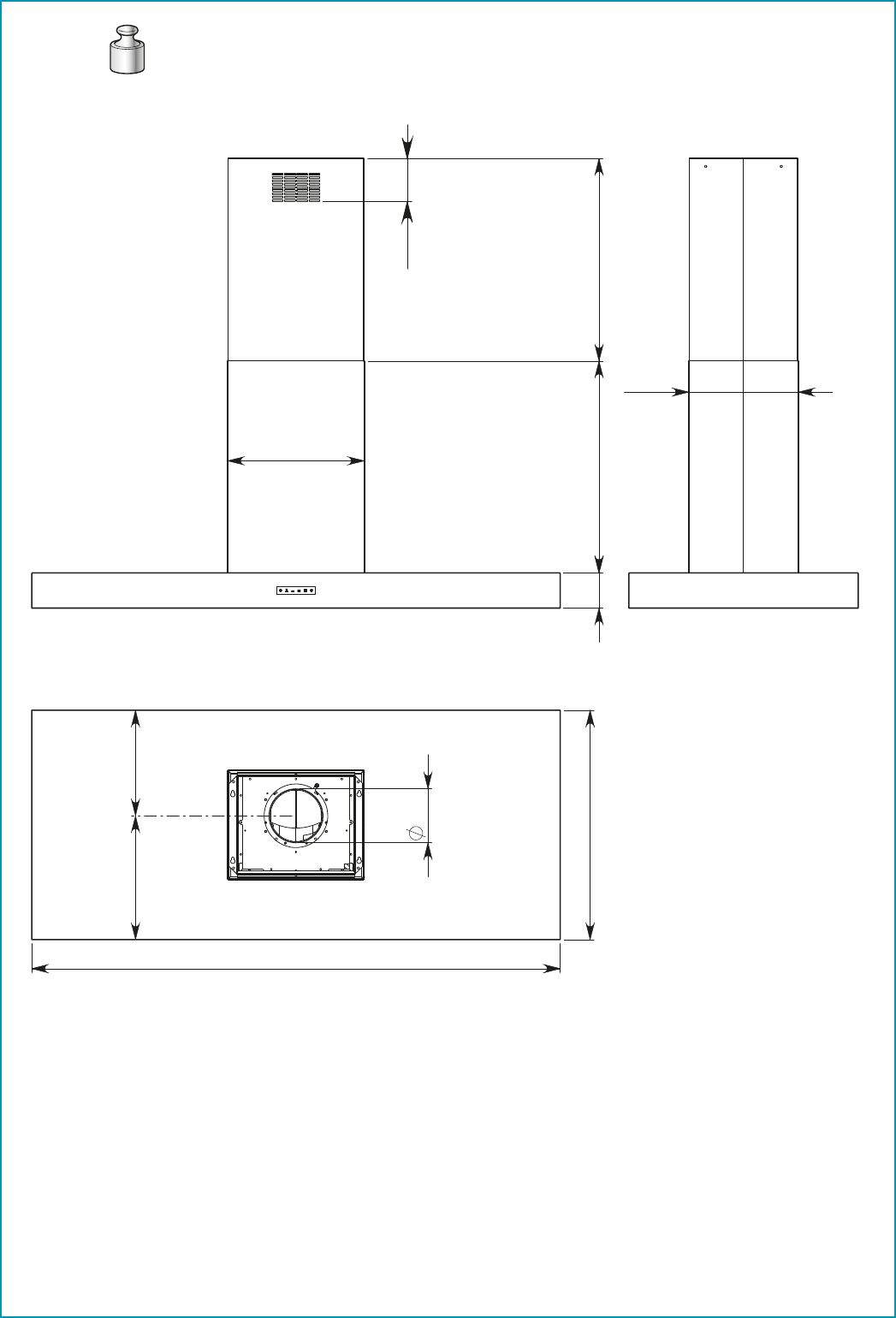
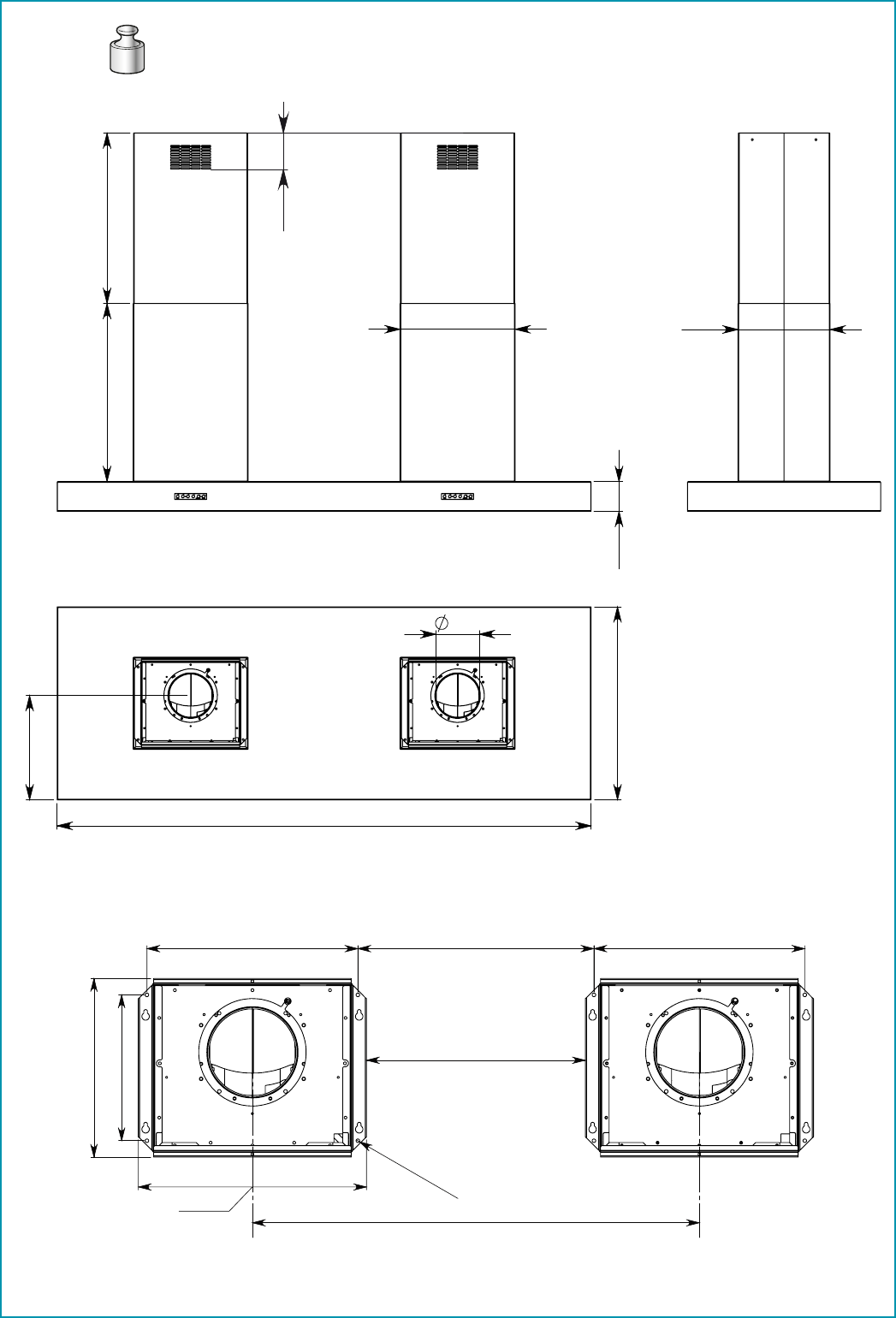
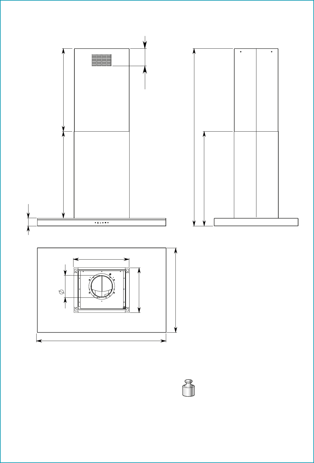
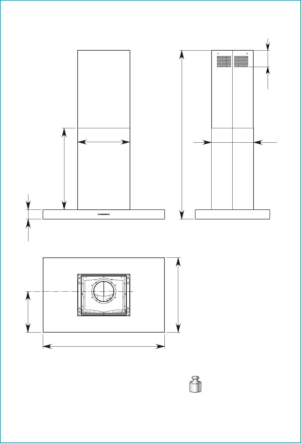
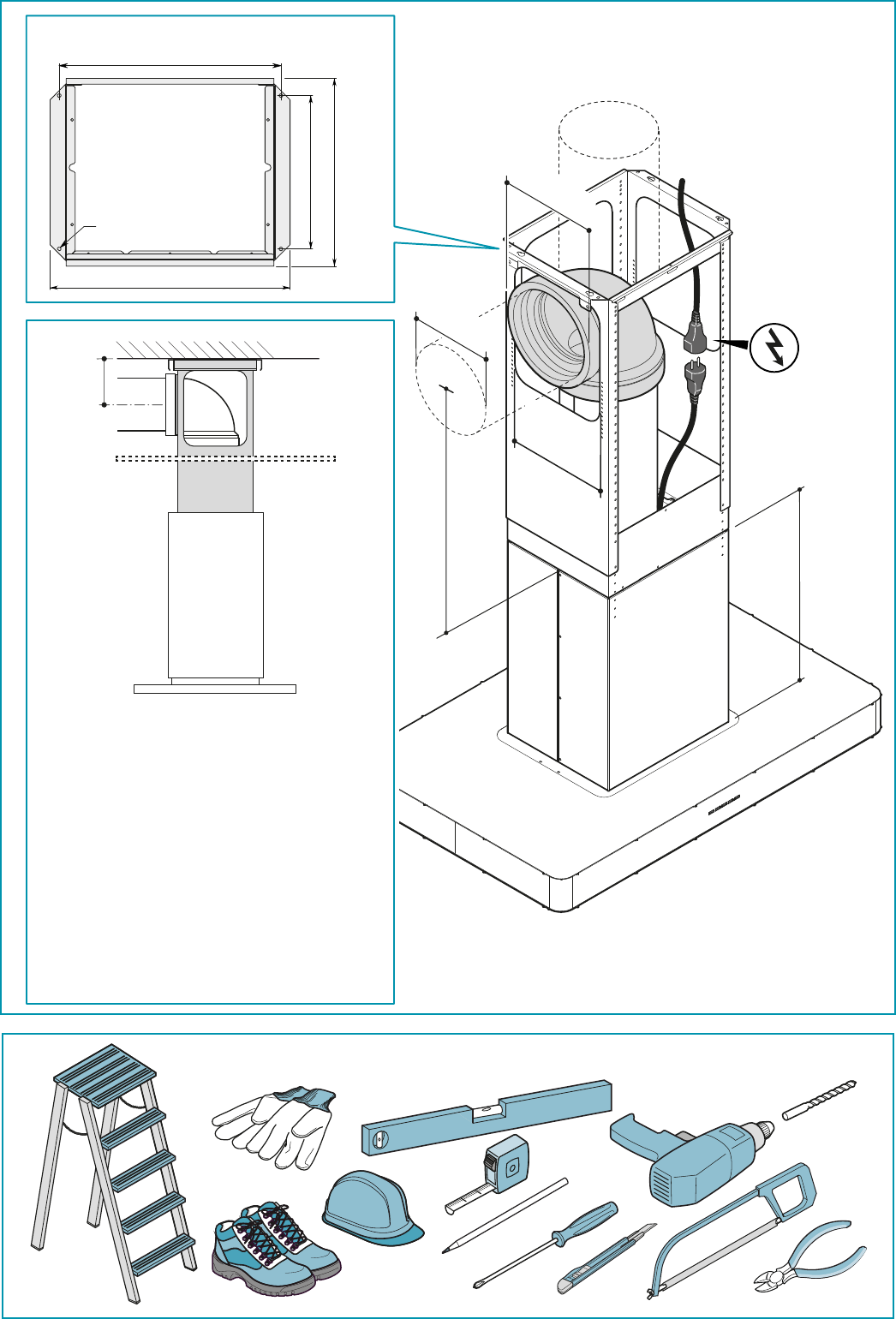
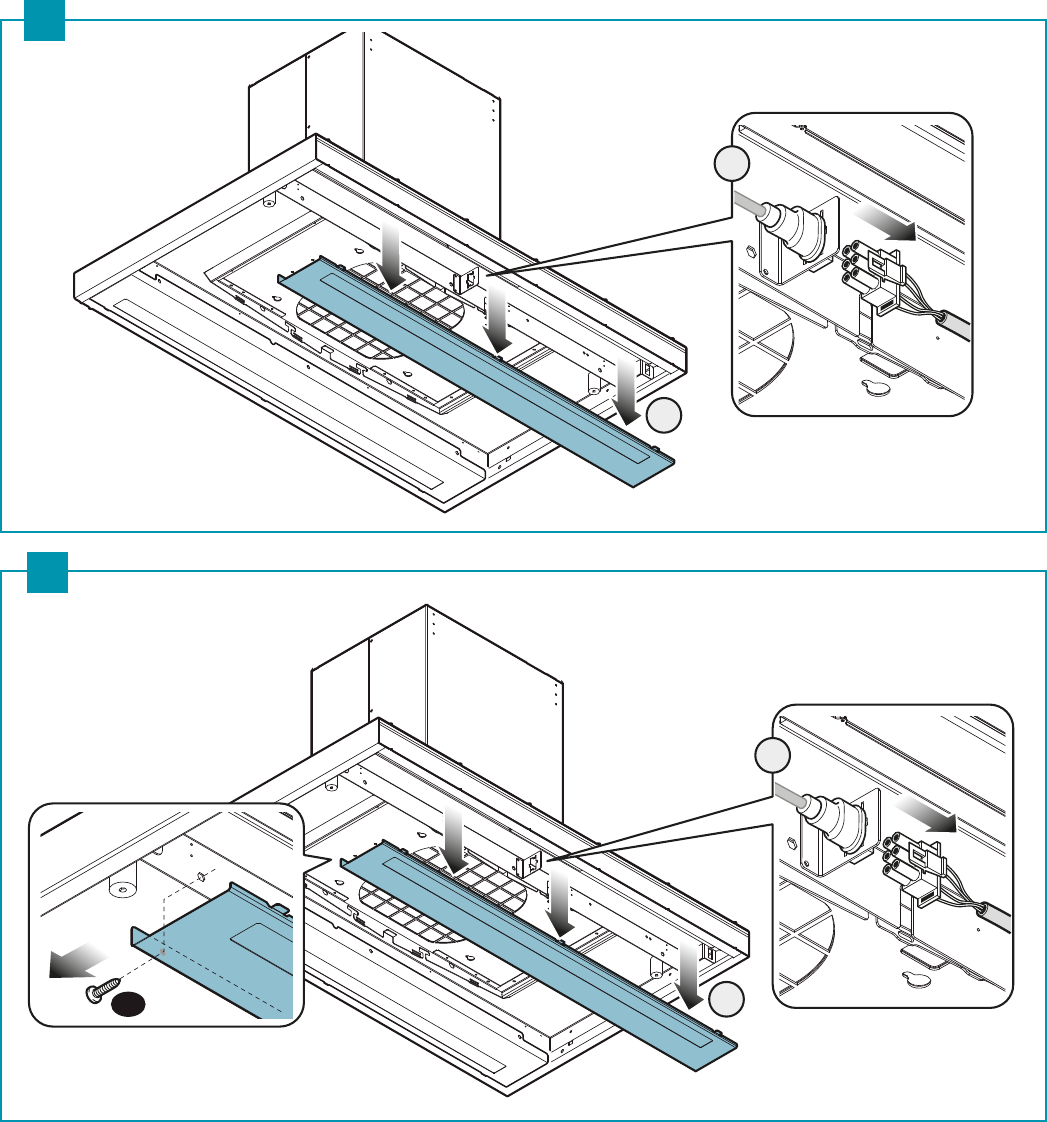
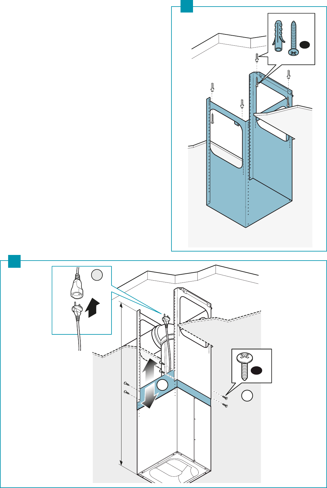
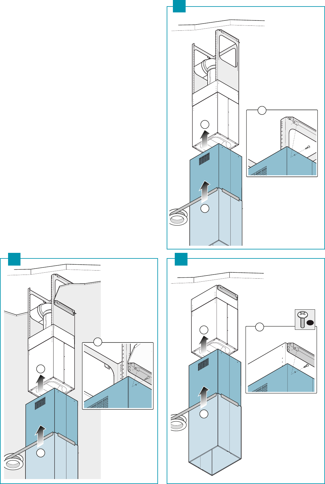
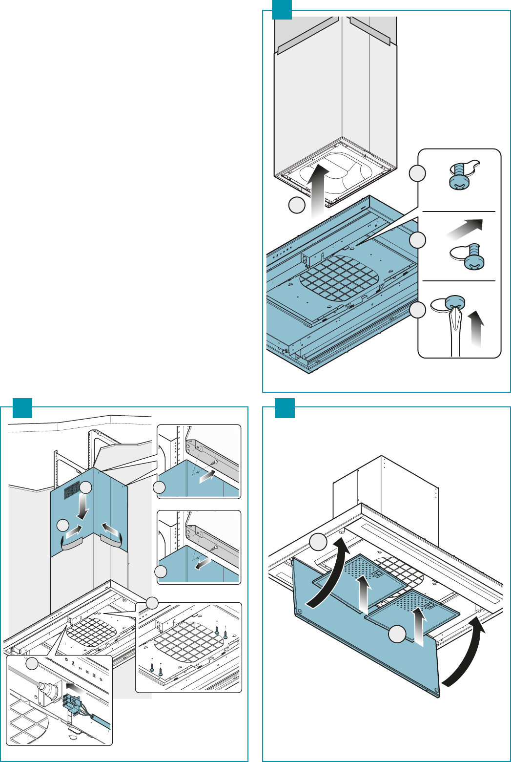
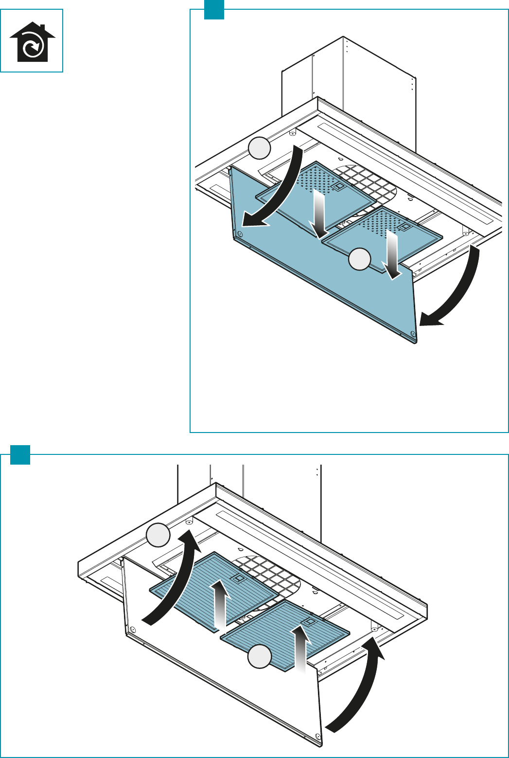
ISTRUZIONI DI MONTAGGIO
parte riservata solo a personale qualicato
La cappa ha la possibilità di essere installata in varie congurazioni.
Le fasi di montaggio generiche valgono per tutte le installazioni; seguire
invece dove specicato le fasi corrispondenti all’installazione desiderata.
FUNZIONAMENTO
QUANDO ACCENDERE LA CAPPA?
Accendere la cappa almeno un minuto prima di iniziare a cucinare per convogliare fumi e
vapori verso la superficie di aspirazione.
Al termine della cottura lasciare in funzione la cappa fino a completa aspirazione di tutti i
vapori e odori: con la funzione Timer, è possibile impostare l'autospegnimento della cappa
dopo 15 minuti di funzionamento.
QUALE VELOCITÀ SCEGLIERE?
I velocità: mantiene l’aria pulita con bassi consumi di energia elettrica.
II velocità: condizioni normali di utilizzo.
III velocità: presenza di forti odori e vapori.
IV velocità: rapidi smaltimenti di odori e vapori.
QUANDO LAVARE O CAMBIARE I FILTRI?
I filtri metallici devono essere lavati ogni 30 ore di utilizzo.
I filtri carbone attivo HP (opzionali), devono essere riattivati ogni 3-4 mesi a seconda dell’utilizzo della
cappa.
Per ulteriori dettagli vedere cap “MANUTENZIONE”.
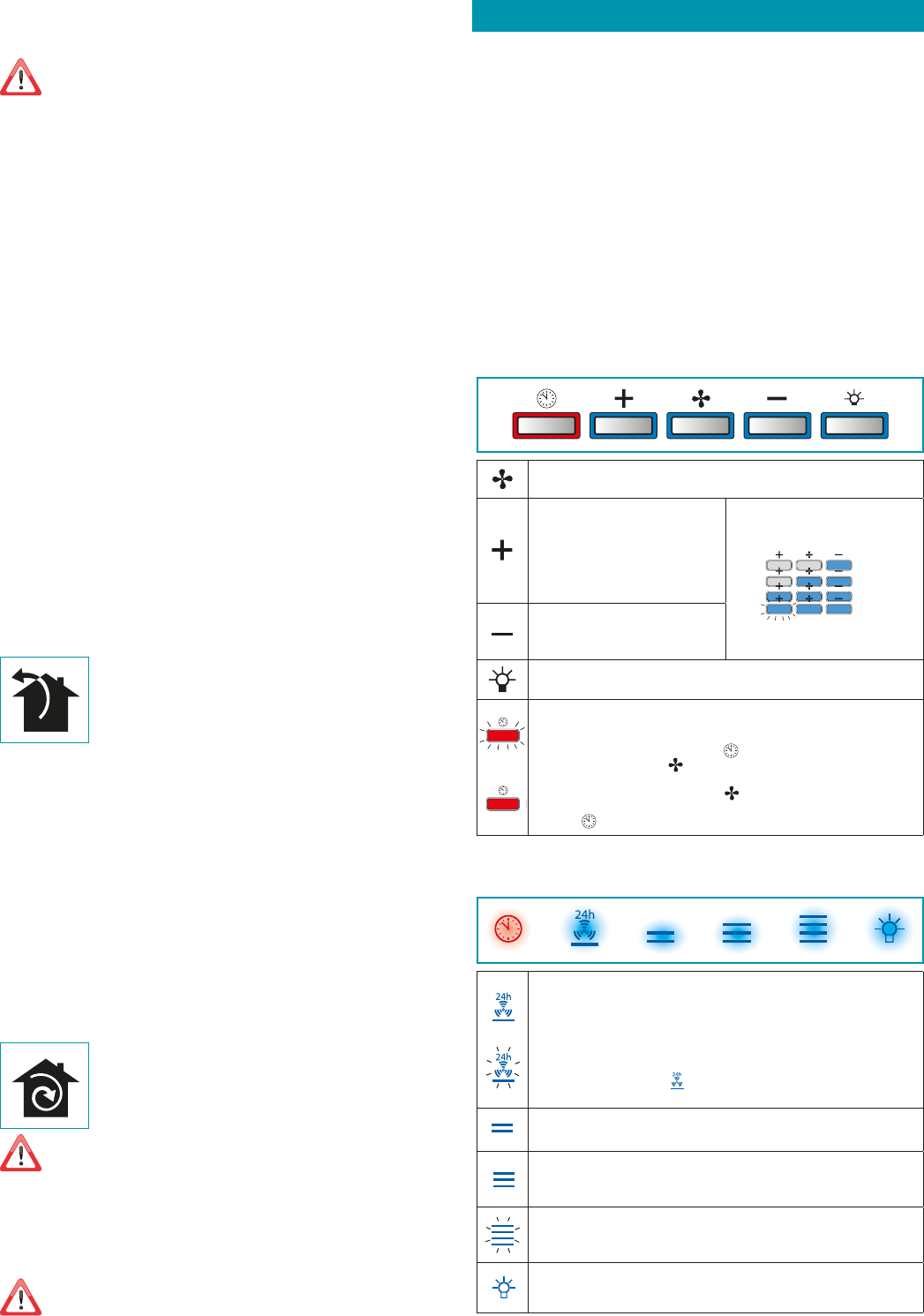
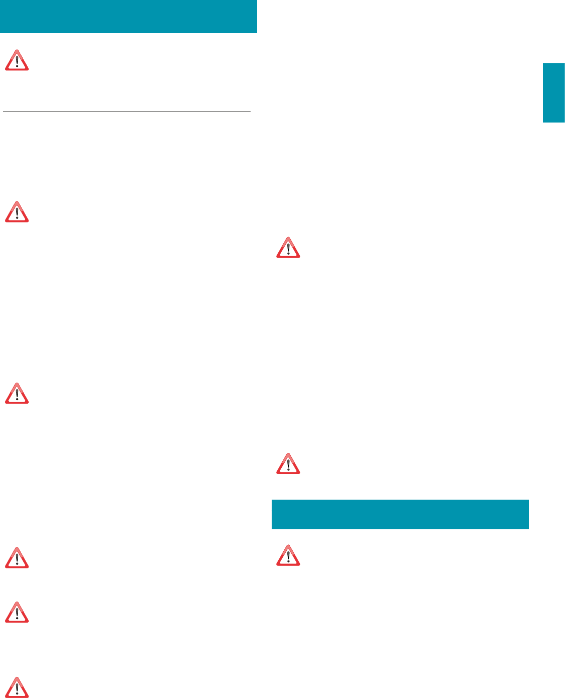
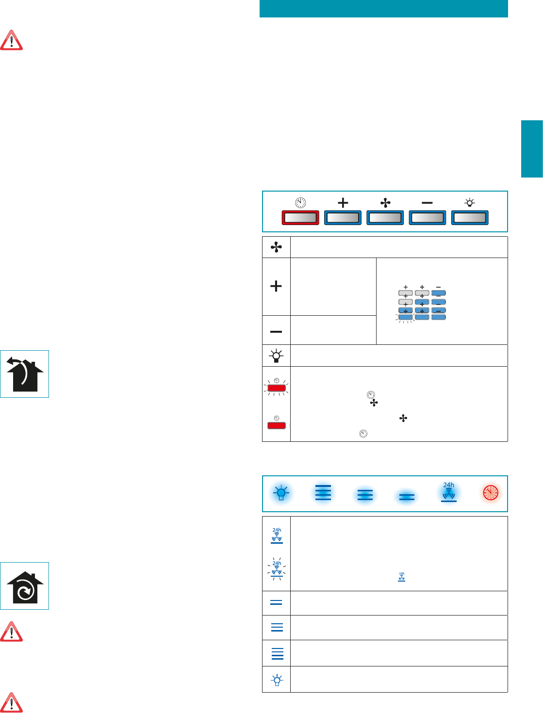
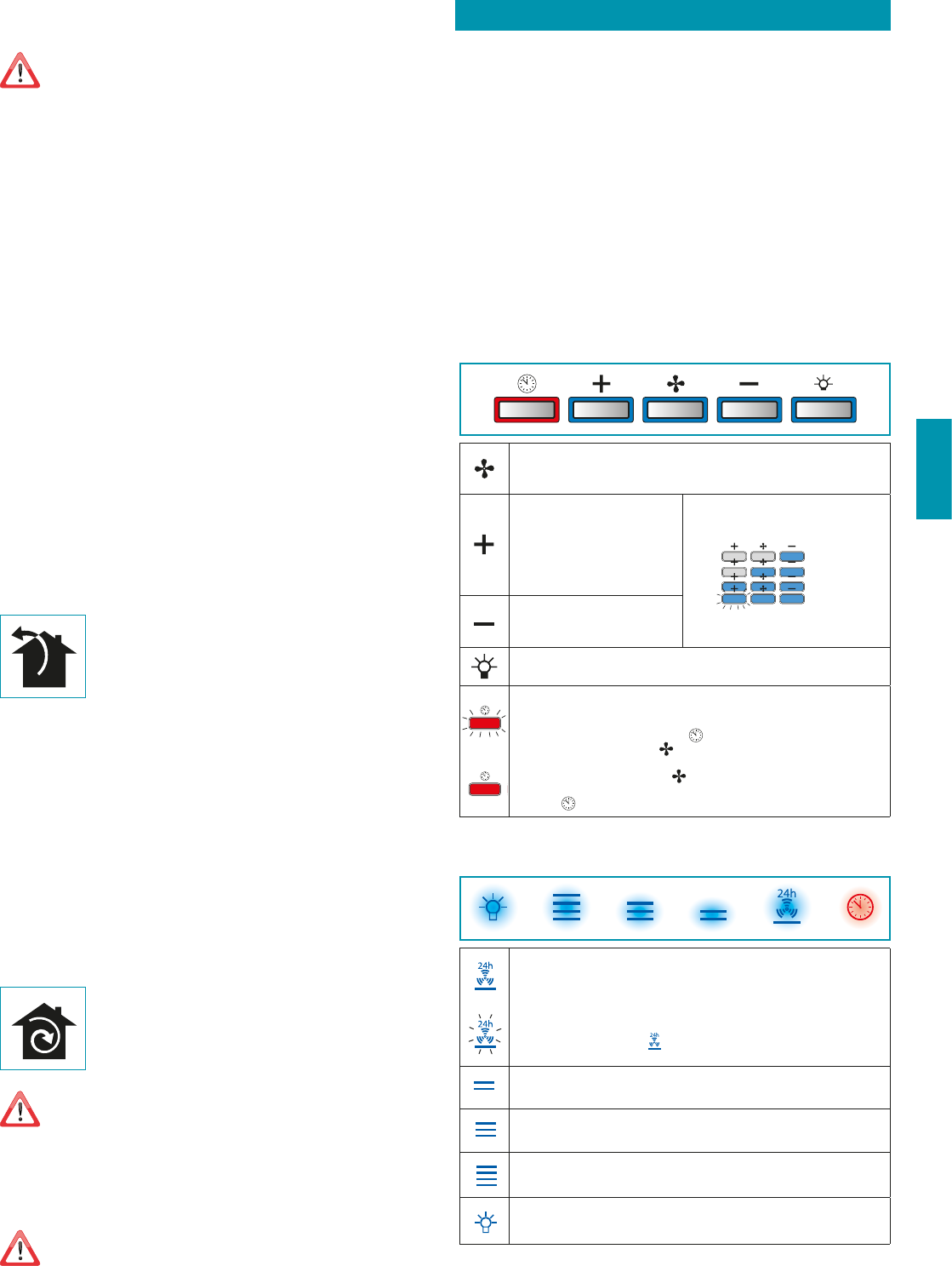
PULSANTIERA ELETTRONICA (STILO e PLANE)
Motore ON/OFF
All’avvio, la velocità è quella memorizzata al precedente spegnimento.
Incremento velocità da 1 a 4
Velocità 4 è attiva solo per alcuni mi-
nuti, poi si attiva velocità 3.
Le velocità sono segnalate dai led
presenti nei tasti:
Velocità 1
Velocità 2
Velocità 3
Velocità 4
(led "+" lampeggiante)
Riduzione velocità da 4 a 1
Accensione / spegnimento luce
TIMER (Led rosso lampeggiante)
Autospegnimento dopo 15min.
La funzione si disattiva (Led rosso spento) se:
- Si preme un'altra volta il tasto TIMER (
).
- Si preme il tasto ON/OFF (
).
ALLARME FILTRI (Led rosso fisso con (
) off)
Manutenzione filtri antigrasso dopo circa 30 ore di utilizzo.
Premere (
) per 3 secondi per azzerare il contatore.
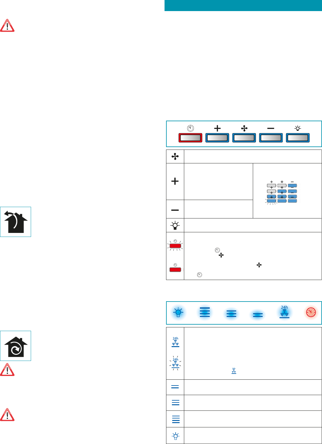
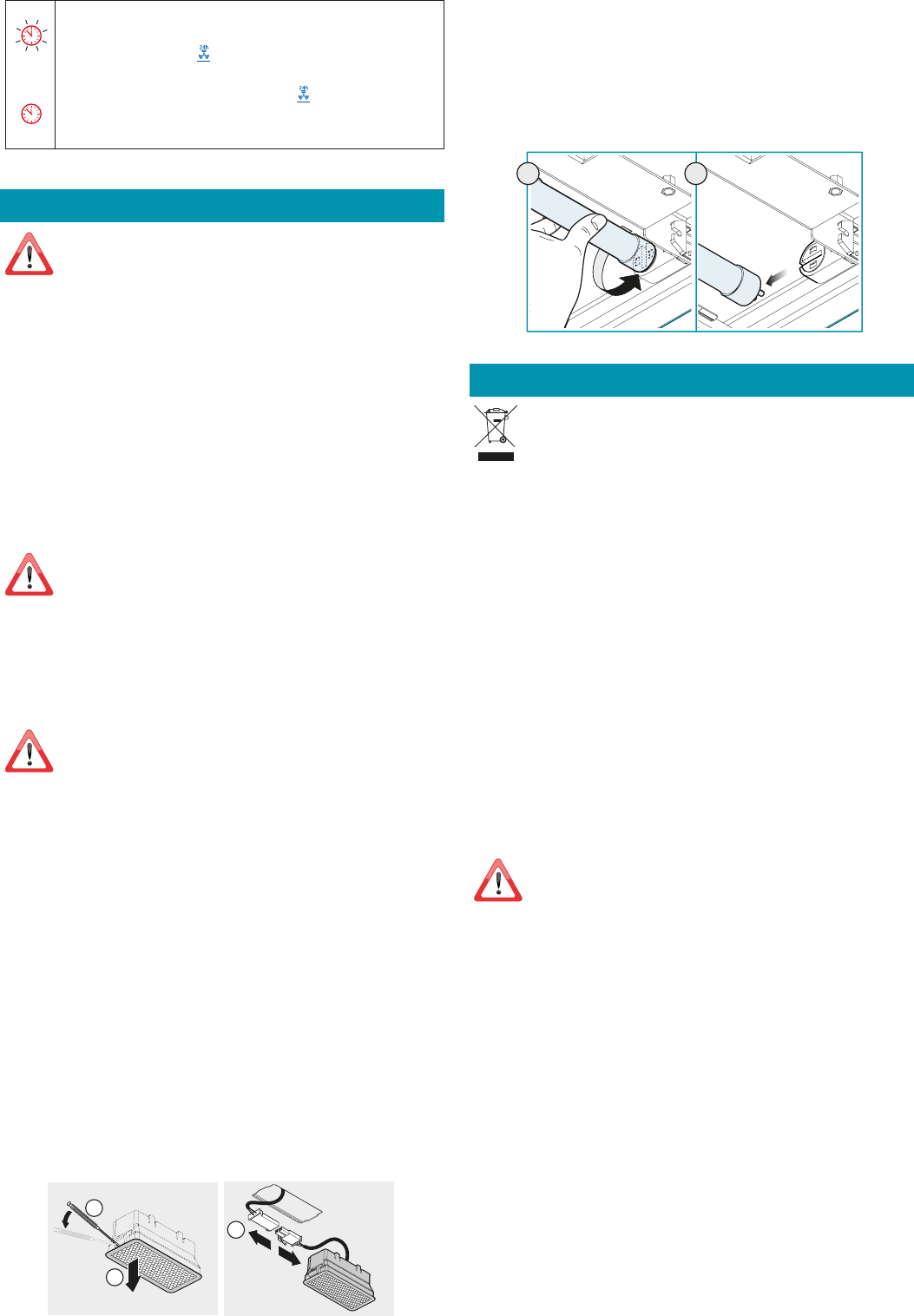
PULSANTIERA TOUCH
ON/OFF (led blu sso)
Accensione/spegnimento motore e Vel1
ON/OFF (led blu lampeggiante)
Premuto per più di 3 secondi attiva il ciclo 24h (1h ON -> 3h OFF -> 1h ON)
La funzione si disattiva se:
- si spegne il motore (tasto
)
- Dopo 24h
Attivazione Velocità 2
Attivazione Velocità 3
Attivazione Velocità 4 solo per alcuni minuti, poi velocità 3
Accensione / spegnimento luce
25
ITALIANO
MANUTENZIONE
Prima di procedere a qualsiasi operazione di pulizia o di manutenzione,
disinserire l’apparecchio togliendo la spina o agendo sull’interruttore ge-
nerale.
Non si devono utilizzare detergenti contenenti sostanze abrasive, acide o
corrosive e panni con superci ruvide.
Una costante manutenzione garantisce un buon funzionamento e rendimento nel tempo.
Particolari attenzioni vanno rivolte ai filtri metallici antigrasso: la pulizia frequente dei filtri
e dei loro supporti garantisce che non si accumulino grassi infiammabili.
PULIZIA SUPERFICI ESTERNE
Si raccomanda di pulire le superfici esterne della cappa almeno ogni 15 giorni per evitare
che le sostanze oleose o grasse possano intaccarle. Per la pulizia della cappa, realizzata in
acciaio inox spazzolato, il Costruttore consiglia l'utilizzo delle salviette "Magic Steel" che si
possono anche ordinare on-line sul sito www.e-falmec.com.
In alternativa e per tutti gli altri tipi di superci, la pulizia va eseguita usando un panno
umido leggermente imbevuto di detersivo neutro liquido o con alcool denaturato.
Terminare la pulizia con un accurato risciacquo e asciugatura con panni morbidi.
Non utilizzare troppa acqua in prossimità della pulsantiera e dei dispositi-
vi di illuminazione per evitare che l'umidità raggiunga parti elettroniche.
La pulizia dei pannelli in vetro va eseguita solo con detergenti specifici non corrosivi o abra-
sivi utilizzando un panno morbido.
Il Costruttore declina ogni responsabilità qualora non vengano rispettate tali istruzioni.
PULIZIA SUPERFICI INTERNE
E’ vietata la pulizia di parti elettriche o parti relative al motore all’interno
della cappa, con liquidi o solventi.
Per le parti metalliche interne vedi paragrafo precedente.
FILTRI METALLICI ANTIGRASSO
Si consiglia di lavare frequentemente i filtri metallici (almeno ogni mese) lasciandoli in
ammollo per circa 1 ora in acqua bollente con detersivo per piatti, evitando di piegarli.
Non usare detergenti corrosivi, acidi o alcalini.
Risciacquarli con cura ed attendere che siano ben asciutti prima di rimontarli.
Il lavaggio in lavastoviglie è permesso, ma potrebbe creare imbrunimenti al materiale dei
filtri: per ridurre questo inconveniente utilizzare lavaggi a basse temperature (55°C max.).
Per l’estrazione e l'inserimento dei filtri metallici antigrasso vedi istruzioni di montaggio.
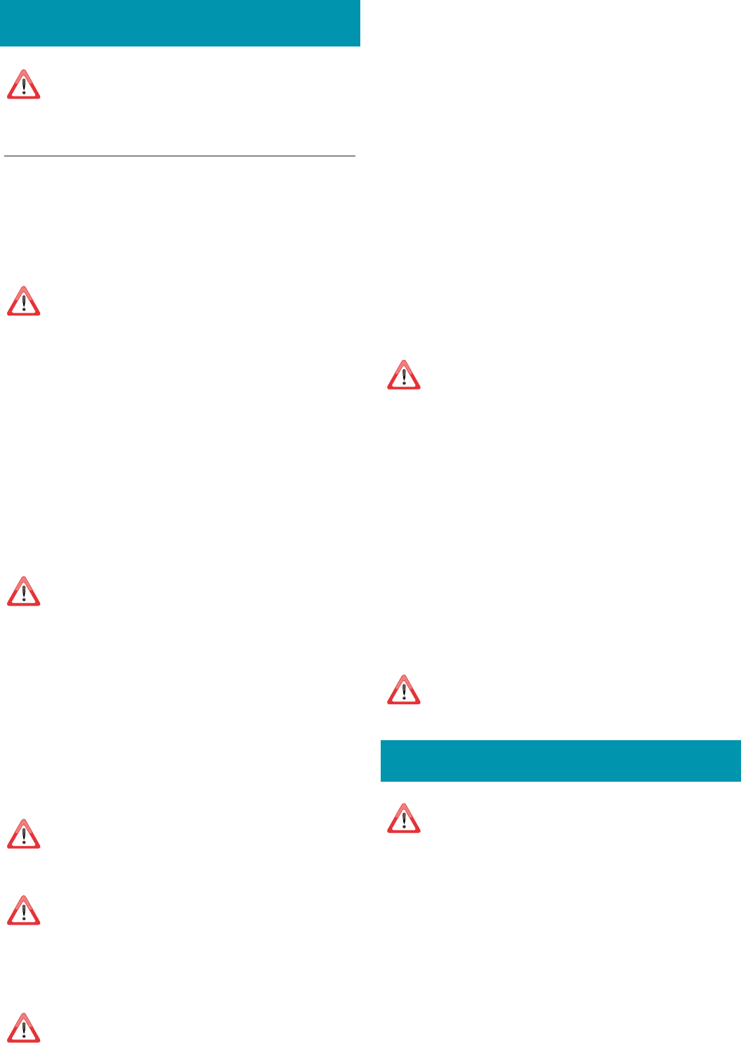
FILTRI AL CARBONE ATTIVO/HP (opzionali)
Questi filtri trattengono gli odori presenti nell’aria che li attraversa. L’aria depurata viene
così rimessa nell’ambiente.
I filtri al carbone attivo HP
si riattivano
lavandoli da soli in lavastoviglie con un normale
detergente ad una temperatura di max 65°C. e passandoli in forno a 80°C per 20 minuti.
La massima durata del filtro è di 2/3 anni con massimo 10 lavaggi per anno.
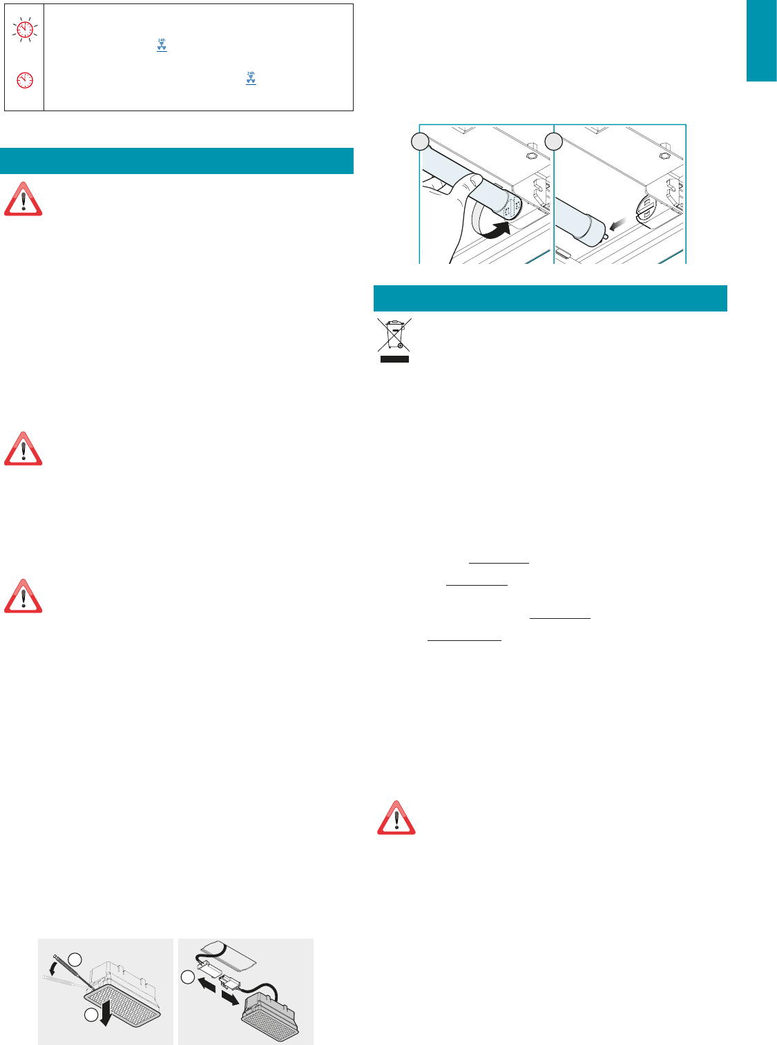
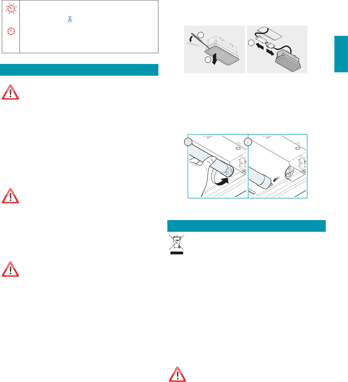
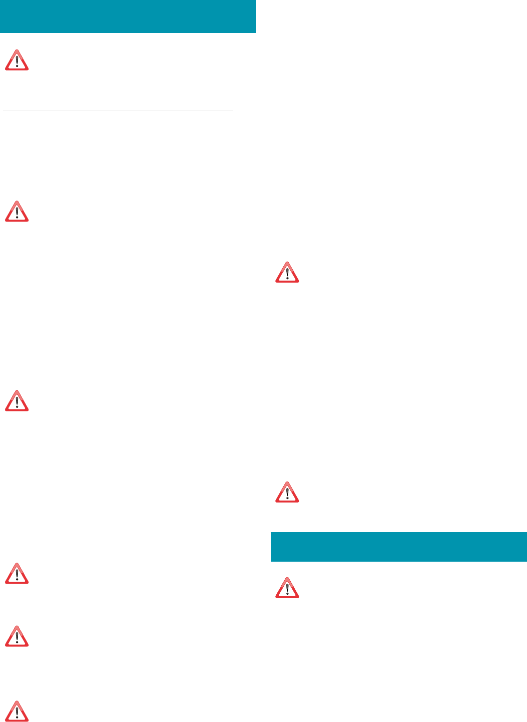
ILLUMINAZIONE (STILO e PLANE)
La cappa è dotata di illuminazione tramite faretti led ad alta efficienza, basso consumo e
durata molto elevata in condizioni di normale utilizzo.
Nel caso si rendesse necessaria la sostituzione del faretto procedere come in figura.
12V
3
1
2
ILLUMINAZIONE (VELA)
La cappa è dotata di illuminazione tramite led ad alta efficienza, basso consumo e durata
molto elevata in condizioni di normale utilizzo.
Nel caso si rendesse necessaria la loro sostituzione rivolgersi ad un centro assistenza.
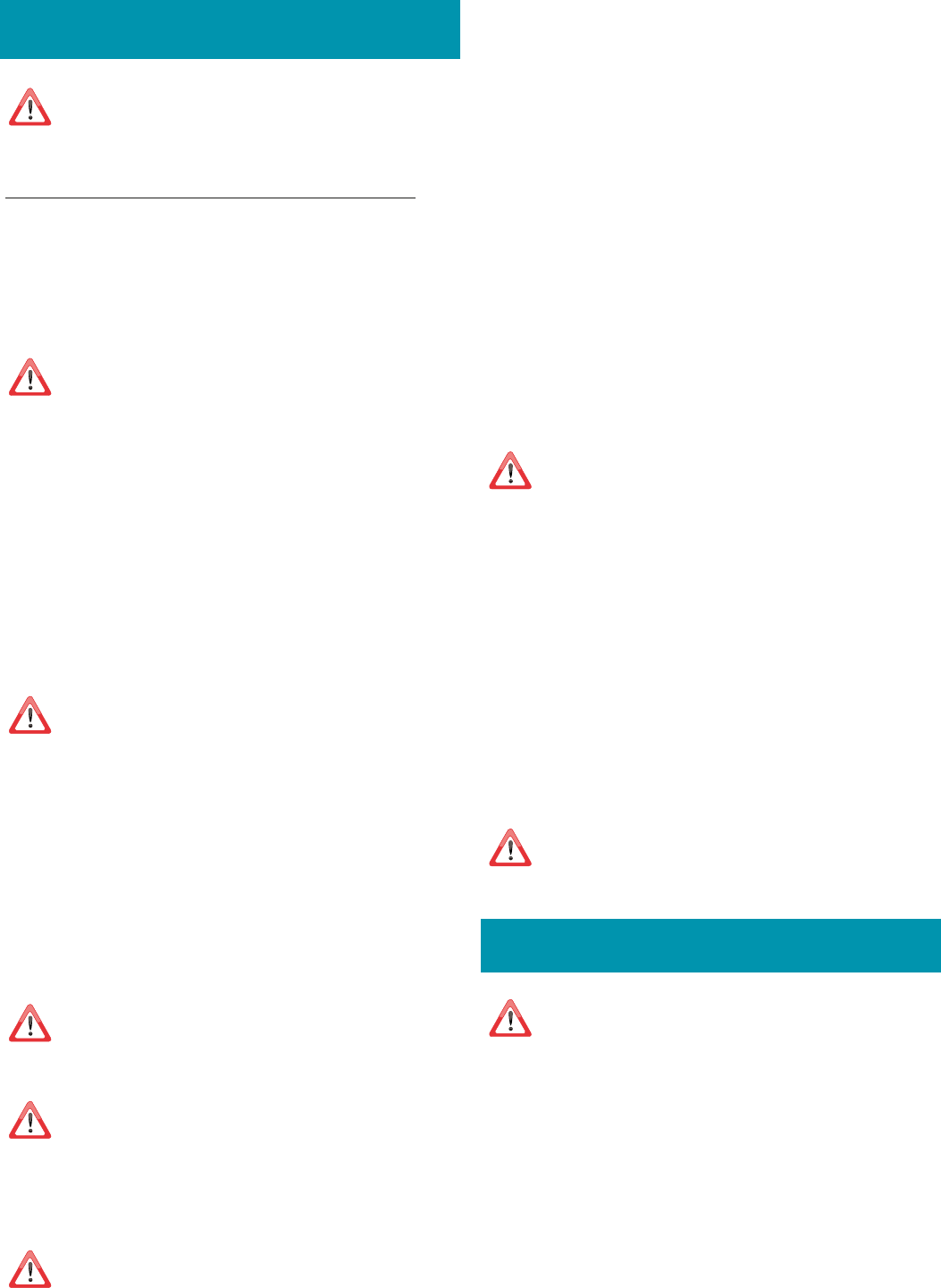
ILLUMINAZIONE (HORIZON e LUMINA)
La cappa e dotata di illuminazione tramite lampada fluorescente.
Qualora si rendesse necessaria la sostituzione di quest'ultima, procedere come in figura.
12
SMALTIMENTO A FINE VITA
Il simbolo del cestino barrato riportato sull’apparecchiatura in suo possesso indi-
ca che il prodotto è un RAEE, cioè un “Rifiuto derivante dalle Apparecchiature
Elettriche ed Elettroniche” e pertanto non deve essere gettato nella spazzatu-
ra indierenziata (cioè insieme ai “rifiuti urbani misti”), ma deve essere gestito
separatamente così da essere sottoposto ad apposite operazioni per il suo riutilizzo, oppure
a uno specifico trattamento, per rimuovere e smaltire in modo sicuro le eventuali sostanze
dannose per l’ambiente ed estrarre le materie prime che possono essere riciclate. Lo smalti-
mento corretto di questo prodotto contribuirà a salvare preziose risorse ed evitare potenzia-
li effetti negativi per la salute umana e per l’ambiente, che potrebbero essere causati da uno
smaltimento inappropriato dei rifiuti.
Vi preghiamo di contattare le autorità locali per ulteriori dettagli sul punto di smaltimento
designato più vicino. Potrebbero venire applicate delle penali per lo smaltimento scorretto
di questi rifiuti in conformità alla legislazione nazionale.
INFORMAZIONI SULLO SMALTIMENTO IN ITALIA
In Italia le apparecchiature RAEE devono perciò essere consegnate:
- ai Centri di Raccolta (chiamati anche isole ecologiche o piattaforme ecologiche) allestiti
dai Comuni o dalle Società di igiene urbana (in molte località viene anche effettuato il
servizio di ritiro a domicilio delle apparecchiature RAEE ingombranti);
- al negozio presso il quale si acquista una nuova apparecchiatura, che è tenuto a ritirarle
gratuitamente (ritiro “uno contro uno”);
- ad un negozio qualunque*, che è tenuto a ritirarle gratuitamente e senza obbligo di
acquisto (ritiro “uno contro zero”).
In questo caso:
1) l’apparecchiatura RAEE, per poter essere riconsegnata, deve avere “piccolissime dimen-
sioni” (altezza, profondità e larghezza minori di 25 cm);
* 2) il negozio al quale viene riconsegnata l’apparecchiatura RAEE deve avere una superficie
di vendita superiore a 400 mq.
INFORMAZIONI SULLO SMALTIMENTO IN NAZIONI DELL'UNIONE EUROPEA
La Direttiva comunitaria sulle apparecchiature RAEE è stata recepita in modo diverso da
ciascuna nazione, pertanto se si desidera smaltire questa apparecchiatura suggeriamo di
contattare le autorità locali o il Rivenditore per chiedere il metodo corretto di smaltimento.
INFORMAZIONI SULLO SMALTIMENTO IN NAZIONI NON APPARTENENTI ALL'UNIO
NE EUROPEA
Il simbolo del cestino barrato è valido solamente nell’Unione Europea: se si desidera smaltire
questa apparecchiatura in altri Paesi suggeriamo di contattare le autorità locali o il Rivendi-
tore per chiedere il metodo corretto di smaltimento.
ATTENZIONE!
Il Costruttore si riserva il diritto di apportare modifiche alle apparecchiature in qualsiasi
momento e senza preavviso. La stampa, la traduzione e la riproduzione anche parziale del
presente manuale s’intendono vincolate dall’autorizzazione del Costruttore.
Le informazioni tecniche, le rappresentazioni grafiche e le specifiche presenti in questo ma-
nuale sono indicative e non divulgabili.
La lingua di stesura del manuale è l’italiano, il Costruttore non si rende responsabile per
eventuali errori di trascrizione o traduzione.
TIMER (Led rosso lampeggiante)
Autospegnimento dopo 15min.
La funzione si disattiva (Led rosso spento) se:
- Si spegne il motore (tasto
).
- Si varia la velocità.
ALLARME FILTRI (Led rosso fisso con motore OFF
)
Manutenzione filtri antigrasso dopo circa 30 ore di utilizzo.
Premere per 3 secondi per azzerare il contatore.
26
GARANZIA (solo per l'Italia)
La sua nuova apparecchiatura è coperta da garanzia. Le condizioni di garanzia sono riporta-
te per esteso nel paragrafo successivo.
La casa costruttrice non risponde delle possibili inesattezze, imputabili ad
errori di stampa o di trascrizione, contenute nel presente libretto.
Si riserva di apportare ai propri prodotti quelle modiche che ritenesse
necessarie o utili, anche nell’interesse dell’utenza, senza pregiudicare le
caratteristiche essenziali di funzionalità e di sicurezza.
CONDIZIONI DI GARANZIA (solo per l'Italia)
IMPORTANTE!
La presente garanzia è valida solo per l’Italia (Guarantee conditions are
valid only for Italy).
DECRETO LEGISLATIVO DEL 30/06/2003 N. 196 - ART. 7
Codice in materia di protezione dei dati personali.
1. L’interessato ha diritto di ottenere la conferma dell’esistenza o meno di dati personali
che lo riguardano, anche se non ancora registrati, e la loro comunicazione in forma
intelleggibile.
2. L’interessato ha diritto di ottenere l’indicazione:
a) dell’origine dei dati personali;
b) delle finalità e modalità del trattamento;
c) della logica applicata in caso di trattamento effettuato con l’ausilio di strumenti elet-
tronici;
d) degli estremi identificativi del titolare, dei responsabili e del rappresentante designa-
to ai sensi dell’articolo 5, comma 2;
e) dei soggetti o delle categorie di soggetti ai quali i dati personali possono essere co-
municati o che possono venirne a conoscenza in qualità di rappresentante designato
nel territorio dello Stato, di responsabili o incaricati.
3. L’interessato ha diritto di ottenere:
a) l’aggiornamento, la rettificazione ovvero, quando vi ha interesse, l’integrazione dei
dati;
b) la cancellazione, la trasformazione in forma anonima o il blocco dei dati trattati in
violazione di legge, compresi quelli di cui non è necessaria la conservazione in relazione
agli scopi per i quali i dati sono stati raccolti o successivamente trattati;
c) l’attestazione che le operazioni di cui alle lettere a) e b) sono state portate a cono-
scenza, anche per quanto riguarda il loro contenuto , di coloro ai quali i dati sono stati
comunicati o diffusi, eccettuato il caso in cui tale adempimento si rileva impossibile o
comporta un impiego di mezzi manifestamente sproporzionato rispetto al diritto tute-
lato.
4. L’interessato ha diritto di opporsi, in tutto o in parte:
a) per motivi legittimi al trattamento dei dati personali che lo riguardano, ancorché
pertinenti allo scopo della, raccolta;
b) al trattamento di dati personali che lo riguardano a fini di invio di materiale pubblici-
tario o di vendita diretta o per il compimento di ricerche di mercato o di comunicazione
commerciale.
Titolare del trattamento dei dati è Falmec S.P.A.
Via dell’Artigianato, 42 - Vittorio Veneto (TV).
CONDIZIONI DI GARANZIA
•L’apparecchio è garantito dalla Casa costruttrice Falmec S.p.A (www.falmec.com) per un
periodo di 24 mesi dalla data del suo acquisto comprovata da ricevuta fiscale o altro
documento reso fiscalmente obbligatorio.
• La garanzia sarà prestata con la sostituzione o riparazione gratuita delle parti che risultino
difettose per vizi delle stesse imputabili a Falmec S.p.A..
• Non sono coperte dalla presente garanzia tutte le parti che dovessero risultare difetto-
se, danneggiate e/o viziate a causa di uso improprio dell’apparecchio, di negligenza o
trascuratezza nell’uso (mancata osservanza delle istruzioni per il funzionamento dell’ap-
parecchio), di inesatta installazione, di mancata ovvero errata manutenzione, di manu-
tenzioni operate da personale non autorizzato, di danni da trasporto, ovvero per circo-
stanze non riferibili a difetti di funzionamento imputabili a Falmec S.p.A. e/o comunque
direttamente imputabili alla Casa costruttrice. Si precisa inoltre che non rientrano nelle
prestazioni in garanzia gli interventi inerenti l’installazione e l’allacciamento agli impianti
elettrici e/o di alimentazione.
• Vengono peraltro esclusi dalla presente garanzia i componenti dell’apparecchio soggetti
ad usura, quali specificatamente ma non esaustivamente: lampadine di varie tipologie,
filtri metallici, filtri carbone, ecc.
• La Casa costruttrice declina ogni responsabilità per eventuali danni che possono, diret-
tamente o indirettamente, essere causati a persone, cose ed animali domestici in con-
seguenza alla mancanza di tutte le prescrizioni indicate nell’apposito libretto istruzioni
e concernenti, specialmente, le avvertenze in tema di installazione, uso e manutenzione
dell’apparecchio.
• Trascorsi i 24 mesi, l’apparecchio non sarà più coperto da garanzia e l’assistenza verrà pre-
stata addebitando le parti sostituite, le spese di manodopera e di trasporto dei personale
e dei materiali, secondo le tariffe vigenti in possesso dei personale dei Servizio Assistenza
Tecnica autorizzato dalla Casa costruttrice. In presenza di un intervento effettuato pres-
so un Centro Assistenza Tecnica autorizzato, l’apparecchio vi sarà recapitato a spese e
rischio dell’utente.
• La presente garanzia è valida per la fornitura ed installazione dell’apparecchio avvenuta
nel solo territorio italiano.
Titolare del trattamento dei dati è Falmec S.P.A.
Via dell’Artigianato, 42 - Vittorio Veneto (TV).
CERTIFICATO DI GARANZIA SOLO PER ITALIA DA CONSERVARE
Questo certicato di garanzia non deve essere spedito, ma conservato con la ricevuta scale, o altro documento reso scalmente obbligatorio, che comprovi la data
d’acquisto della cappa. In caso necessiti intervenire per anomalie di funzionamento, si prega di contattare un Centro di Assistenza Tecnica autorizzato, tenendo a
portata di mano i dati sotto indicati:
Matricola/Serial Number (vedere ultima pagina libretto o targhetta dei dati tecnici posta all'interno della cappa):
È ASSOLUTAMENTE NECESSARIO INDICARE IL NUMERO MATRICOLA DELLA CAPPA.
Questo apparecchio viene garantito per 2 anni dalla data di acquisto contro difetti di materiale e/o di fabbricazione.
Questo certicato è valido e operante solo se conservato assieme alla ricevuta scale o altro documento reso scalmente obbligatorio.
Rivenditore:
Città:
Data d’acquisto:
27
ENGLISH
SAFETY INSTRUCTIONS
AND WARNINGS
Installation operations are to be carried out by skilled and qualied in-
stallers in accordance with the instructions in this booklet and in compli-
ance with the regulations in force.
DO NOT use the hood if the power supply cable or other components are damaged:
disconnect the hood from the electrical power supply and contact the Dealer or an author-
ised Servicing Dealer for repairs.
Do not modify the electrical, mechanical or functional structure of the equipment.
Do not personally try to carry out repairs or replacements. Interventions carried out
by incompetent and unauthorised persons can cause serious damage to the unit or
physical and personal harm, not covered by the Manufacturer's warranty.
WARNINGS FOR THE INSTALLER
TECHNICAL SAFETY
Before installing the hood, check the integrity and function of each part.
Should anomalies be noted, do not proceed with installation and contact
the Dealer.
Do NOT install the hood if an aesthetic (or cosmetic) defect has been detected. Put it
back into its original package and contact the dealer.
No claim can be made for aesthetic (or cosmetic) defects once it has been installed.
During installation, always use personal protective equipment (e.g.: Safety shoes) and adopt
prudent and proper conduct.
The installation kit (screws and plugs) supplied with the hood is only to be used on masonry
walls: in case of installation on walls of a different material, assess other installation options
keeping in mind the type of wall surface and the weight of the hood (indicated on page 2).
Keep in mind that installations with different types of fastening systems from those sup-
plied, or which are not compliant, can cause electrical and mechanical seal danger.
Do not install the hood outdoors and do not expose it to atmospheric elements (rain, wind,
etc.).
ELECTRICAL SAFETY
The electrical system to which the hood is to be connected must be in ac-
cordance with local standards and supplied with earthed connection in
compliance with safety regulations in the country of use. It must also com-
ply with European standards regarding radio antistatic properties.
Before installing the hood, check that the electrical mains power supply corresponds with
what is reported on the identification plate located inside the hood.
The socket used to connect the installed equipment to the electrical power supply must
be within reach: otherwise, install a mains switch to disconnect the hood when required.
Any changes to the electrical system must be carried out by a qualified electrician.
The maximum length of the flue fastening screws (supplied by the manufacturer) must be
13 mm. Use of non-compliant screws with these instructions can lead to danger of an elec-
trical nature.
Do not try to solve the problem yourself in the event of equipment malfunction, but contact
the Dealer or an authorised Servicing Department for repairs.
When installing the hood, disconnect the equipment by removing the
plug or switching o the main switch.
FUMES DISCHARGE SAFETY
Do no connect the equipment to discharge pipes of fumes produced from
combustion (for example boilers, replaces, etc.).
Before installing the hood, ensure that all standards in force regarding discharge of air out of
the room have been complied with.
USER WARNINGS
These warnings have been drawn up for your personal safety and those of
others. You are therefore kindly asked to read the booklet carefully in its
entirety before using the or cleaning the equipment.
The Manufacturer declines all responsibility for any damage caused directly, or in-
directly, to persons, things and pets as a consequence of failing to comply with the
safety warnings indicated in this booklet.
It is imperative that this instructions booklet is kept together with the equipment for
any future consultation.
If the equipment is sold or transferred to another person, make sure that the booklet is
also supplied so that the new user can be made aware of the hood's operation and relative
warnings.
After the stainless steel hood has been installed, it will need to be cleaned to remove any
residues remaining from the protection adhesive as well as any grease and oil stains which, if
not removed, can cause irreversible damage to the hood surface. To properly clean the unit,
the manufacturer recommends using the supplied moist wipes, which are also available
sold separately.
Insist on original spare parts.
INTENDED USE
The equipment is solely intended to be used to extract fumes generated from cook-
ing food in non-professional domestic kitchens: any other use is improper. Improper
use can cause damage to persons, things, pets and exempts the Manufacturer from
any liability.
The equipment can be used by children over the age of 8 and by persons with reduced
physical, sensory and mental abilities, or with no experience or knowledge, as long as they
do so under supervision or after having received relative instructions regarding safe use of
the equipment and understanding of the dangers connected to it.
Children are not to play with the equipment. Cleaning and maintenance by the user must
not be carried out by children without supervision.
USE AND CLEANING WARNINGS
Before cleaning or carrying out maintenance operations, disconnect the
equipment by removing the plug or switching o the main switch.
Do not use the hood with wet hands or bare feet.
Always check that all electrical parts (lights, extractor fan) are off when the equipment is
not being used.
The maximum overall weight of any objects placed or hung (if applicable) on the hood must
not exceed 1.5 Kg.
Always supervise the cooking process during the use of deep-fryers: Overheated oil can
catch fire.
Do not leave open, unattended flames under the hood.
Do not prepare food over an open flame under the hood.
Never use the hood without the metal anti-grease filters: in this case, grease and dirt will
deposit in the equipment and compromise its operation.
Accessible parts of the hood can be hot when used at the same time as the cooking ap-
pliances.
Do not carry out any cleaning operations when parts of the hood are still hot.
There can be a risk of fire if cleaning is not carried out according to the instructions and
products indicated in this booklet.
Disconnect the main switch when the equipment is not used for long periods of time.
If other appliances that use gas or other fuels are being used at the same
time (boiler, stove, replaces, etc.), make sure the room where the fumes
are discharged is well-ventilated, in compliance with the local regulations.
INSTALLATION
only intended for qualied personnel
Before installing the hood, carefully read the chapter 'SAFETY INSTRUC-
TIONS AND WARNINGS'.
TECHNICAL FEATURES
The technical specifications are exhibited on the labels located inside the hood.
POSITIONING
The minimum distance between the highest part of the cooking equipment and the
lowest part of the hood is indicated in the installation instructions.
Generally, when the hood is placed over gas cookers, the distance must be at least 65 cm
(25.6''). However, according to an interpretation of standard EN60335-2-31 dated 11-07-
2002 of TC61 (sub-clause 7.12.1 meeting 15 agenda item 10.11), the minimum distance
between the cooker and lower part of the hood can be reduced to the quota reported in
the installation instructions.
Should the instructions for the gas cooker specify a greater distance, this must be taken
into consideration.
Do not install the hood outdoors and do not expose it to outdoor environment (rain, wind,
etc.).
28
ELECTRICAL CONNECTION
(only intended for qualied personnel)
Disconnect the equipment from electrical mains power supply before carry-
ing out any operations on the hood.
Ensure that the wires inside the hood are not disconnected or cut:
in the event of damage, contact your nearest Servicing Department.
Refer to qualied personnel for electrical connections.
Connection must be carried out in compliance with the provisions of law in force.
Before connecting the hood to the electrical mains power supply, check that:
• voltage supply corresponds with what is reported on the data plate located inside the
hood;
• the electrical system is compliant and can withstand the load (see the technical specific-
ations located inside the hood);
• the power supply plug and cable do not come into contact with temperatures exceed-
ing 70 °C;
• the power supply system is effectively and properly connected to earth in compliance
with regulations in force;
•
the socket used to connect the hood is within reach.
In case of:
• devices fitted with cables without a plug: the type of plug to use is a ''standardised'' one.
The wires must be connected as follows: yellow-green for earthing, blue for neutral and
brown for the phase. The plug must be connected to an adequate safety socket.
•
fixed equipment not provided with a power supply cable and plug, or any other device
that ensures disconnection from the electrical mains, with an opening gap of the con-
tacts that enables total disconnection in overvoltage category III conditions.
Said disconnection devices must be provided in the mains power supply in compliance
with installation regulations.
The yellow/green earth cable must not be cut off by the switch.
The Manufacturer declines all responsibility for failure to comply with the safety regulations.
FUMES DISCHARGE
EXTERNAL EXHAUST HOOD SUCTION
In this version the fumes and vapours are discharged outside through
the exhaust pipe.
To this end, the hood outlet fitting must be connected via a pipe, to an
external output.
The outlet pipe must have:
• a diameter not less than that of the hood fitting.
• a slight slope downwards (drop) in the horizontal sections to prevent condensation from
flowing back into the motor.
• the minimum required number of bends.
• the minimum required length to avoid vibrations and reduce the suction performance of
the hood.
You are required to insulate the pipes if it passes through cold environments.
In the presence of motors with 800m
3
/h or higher, a check valve is present to prevent
external air flowing back.
Deviation for Germany:
when the kitchen hood is used at the same time as appliances that are powered by energy other
than electricity, the negative pressure in the room must not exceed 4 Pa (4 x 10⁻⁵ bar).
HOOD WITH INTERNAL RECIRCULATION FILTERING
In this model, air passes through the active carbon filters HP (optio-
nal) to be purified and is then recycled into the environment.
Ensure that the active carbon filters HP are assembled into the hood, if
not, install them as indicated in the assembly instructions.
In this version the check valve must not be assembled: remove it if it is on the air
outlet fitting of the motor.
ASSEMBLY INSTRUCTIONS
only intended for personnel qualied
The hood can be installed in various congurations.
The generic assembly steps apply to all installations; for each case, follow
the specic steps provided for the required installation.
OPERATION
WHEN TO TURN ON THE HOOD?
Switch on the hood at least one minute before starting to cook to direct fumes and vapours
towards the suction surface.
After cooking, leave the hood operating until complete extraction of all vapours and odours.
By means of the Timer function, it is possible to set auto switch-off function which will allow
the hood to turn off automatically after 15 minutes of operation.
WHICH SPEED IS TO BE SELECTED?
1st speed: maintains the circulation of clean air with low electricity consumption.
2nd speed: normal conditions of use.
3rd speed: presence of strong odours and vapours.
4th speed: rapid disposal of odours and vapours.
WHEN SHOULD THE FILTERS BE WASHED OR REPLACED?
The metal filters must be cleaned every 30 hours of operation.
The HP active carbon filters (optional), must be reactivated every 3-4 months, depending
on the use of the hood.
For further details see the “MAINTENANCE” chap.
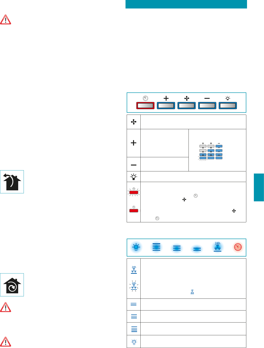
ELECTRONIC PUSHBUTTON PANEL (STILO e PLANE)
Motor ON/OFF
Upon start-up, the speed is that stored at the previous operation.
Increase speed from 1 to 4
Speed 4 is only active for a few
minutes, then speed 3 activates.
The speeds are indicated by the LEDs
on the keys:
Speed 1
Speed 2
Speed 3
Speed 4
("+" LED flashing)
Reduce speed from 4 to 1
Light on/o
TIMER (red LED flashing)
Auto switch-off after 15 min.
The function deactivates (red LED off) if:
- The TIMER key (
) is pressed again.
- The ON/OFF key (
) is pressed.
FILTER ALARM (red LED steady on with (
) off)
Anti-grease filter maintenance after approximately 30 hours of operation.
Press (
) the meter for 3 seconds to reset.
TOUCH PUSHBUTTON PANEL
ON/OFF (Blue led steady on)
Motor on/off and Speed 1
ON/OFF (blue led ashing)
If pressed for more than 3 seconds, it activates the 24h cycle (1h ON -> 3h
OFF -> 1h ON)
the function deactivates if:
- The motor turns off (key
)
- After 24h
Speed 2 activation
Speed 3 activation
Speed 4 activation for a few minutes only
Light on/o
29
ENGLISH
MAINTENANCE
Before cleaning or carrying out maintenance operations, disconnect the
equipment by removing the plug or switching o the main switch.
Do not use detergents containing abrasive, acidic or corrosive substances
or abrasive cloths.
Regular maintenance guarantees proper operation and performance over time.
Special attention is to be paid to the metal anti-grease lters : frequent cleaning of the
filters and their supports ensures that no flammable grease is accumulated.
CLEANING OF EXTERNAL SURFACES
You are advised to clean the external surfaces of the hood at least once every 15 days
to
prevent oily substances and grease from sticking to them. To clean the brushed stainless
steel hood, the Manufacturer recommends using "Magic Steel" wipes.
Alternatively and for all the other types of surfaces, it can be cleaned using a damp cloth,
slightly moistened with mild, liquid detergent or denatured alcohol.
Complete cleaning by rinsing well and drying with soft cloths.
Do not use too much moisture or water around the push button control
panel and lighting devices in order to prevent humidity from reaching
electronic parts.
The glass panels can only be cleaned with specific, non-corrosive or non-abrasive deter-
gents using a soft cloth.
The Manufacturer declines all responsibility for failure to comply with these instructions.
CLEANING OF INTERNAL SURFACES
Do not clean electrical parts, or parts related to the motor inside the hood,
with liquids or solvents.
For the internal metal parts, see the previous paragraph.
METAL ANTI-GREASE FILTERS
It is advised to frequently wash the metal filters (at least once a month) leaving them to
soak in boiling water and cleaning solution for 1 hour, taking care not to bend them.
Do not use corrosive, acid or alkaline detergents.
Rinse them well and wait for them to be completely dry before reassembling them.
Washing in a dishwasher is permitted, however, it may cause the filter material to darken: to
reduce the possibility of this problem from happening, use low-temperature washes (55°C
max.).
To extract and insert the metal anti-grease filters see the assembly instructions.
HP/ACTIVE CARBON FILTERS (optional)
These filters retain the odours in the air that passes through them. The purified air is recir-
culated into the environment.
The HP active carbon filters
reactivate
by washing them in the dishwasher with a normal
detergent at a maximum temperature of 65°C and passing them in the oven at 80°C for
20 minutes.
The maximum duration of the filter is 2/3 years with a maximum of 10 washings per year.
LIGHTING (STILO e PLANE)
The range hood is equipped with high efficiency, low consumption LED spotlights with an
extremely long life-span under normal use conditions.
Should the LED spotlight need to be replaced, proceed as shown in the figure.
12V
3
1
2
LIGHTING (VELA)
The range hood is equipped with high efficiency, low consumption LED with an extremely
long life-span under normal use conditions.
Should the LED spotlight need to be replaced, contact the service centre.
LIGHTING (HORIZON e LUMINA)
The hood has fluorescent lamp lighting.
If the lamp ever needs to be replaced, proceed as shown in the figure.
12
DISPOSAL AFTER END OF USEFUL LIFE
The crossed-out trash or refuse bin symbol on the appliance means that the
product is WEEE, i.e. “Waste electrical and electronic equipment'', accordingly it
must not be disposed of with regular unsorted waste (i.e. with ''mixed house-
hold waste''), but it must be disposed of separately so that it can undergo specific
processing for its re-use, or a specific treatment, to remove and safely dispose of any sub-
stances that may be harmful to the environment and remove the raw materials that can be
recycled. Proper disposal of these products contributes to saving valuable resources and
avoid potential negative effects on personal health and the environment, which may be
caused by inappropriate disposal of waste.
You are kindly asked to contact your local authorities for further information regarding the
designated waste collection points nearest to you. Penalties for improper disposal of such
waste can be applied in compliance with national regulations.
INFORMATION ON DISPOSAL IN EUROPEAN UNION COUNTRIES
The EU WEEE Directive was implemented differently in each country, accordingly, if you wish
to dispose of this appliance we suggest contacting your local authorities or dealer to find
out what the correct method of disposal is.
INFORMATION ON DISPOSAL IN NONEUROPEAN UNION COUNTRIES
The crossed-out trash or refuse bin symbol is only valid in the European Union: if you wish
to dispose of this appliance in other countries, we suggest contacting your local authorities
or dealer to find out what the correct method of disposal is.
WARNING!
The Manufacturer reserves the right to make changes to the equipment at any time and
without prior notice. Printing, translation and reproduction, even partial, of this manual are
bound by the Manufacturer's authorisation.
Technical information, graphic representations and specifications in this manual are for in-
formation purposes and cannot be divulged.
This manual is written in Italian. The Manufacturer is not responsible for any transcription
or translation errors.
TIMER (Red LED flashing)
Auto switch-off after 15 min.
The function deactivates (red LED off) if:
- The motor turns off (key
).
- The speed is changed.
FILTER ALARM (red LED steady on)
Anti-grease filter maintenance after approximately 30 hours of operation.
Press the meter for 3 seconds to reset.
30
ANWEISUNGEN FÜR DIE SICHERHEIT
UND WARNHINWEISE
Die Installation muss von kompetenten und qualizierten Installateuren unter Be-
folgung der Angaben der vorliegenden Gebrauchsanweisung sowie unter Einhal-
tung der gültigen Sicherheitsvorschriften vorgenommen werden.
Wenn das Versorgungskabel oder andere Komponenten beschädigt sind, darf die Abzugshau
-
be NICHT verwendet werden: Die Abzugshaube von der Stromversorgung trennen und den Händ-
ler oder den autorisierten Kundendienst für die Reparatur kontaktieren.
Die elektrische, mechanische und funktionelle Struktur des Geräts darf nicht verändert werden.
Niemals versuchen, Reparaturen oder Austauschtätigkeiten selbst durchzuführen. Werden diese
Arbeiten von Personen durchgeführt, die nicht dazu befähigt und qualiziert sind, so kann dies zu
schweren Personen- und Sachschäden führen, die von der Herstellergarantie nicht gedeckt sind.
HINWEISE FÜR DEN INSTALLATEUR
TECHNISCHE SICHERHEIT
Vor der Installation der Abzugshaube muss sichergestellt werden, dass sämtliche
Komponenten unbeschädigt und funktionstüchtig sind. Sollten Schäden festgestellt
werden, nicht mit der Installation fortfahren und umgehend den Händler kontaktieren.
Sollte ein ästhetischer Mangel festgestellt werden, so darf die Abzugshaube NICHT installiert
werden. Die Abzugshaube wieder verpacken und umgehend den Händler kontaktieren.
Sobald die Abzugshaube installiert ist, werden keine Beanstandungen aufgrund ästhetischer
Mängel mehr akzeptiert.
Während der Installation ist immer eine geeignete persönliche Schutzausrüstung zu tragen (z.B. Si
-
cherheitsschuhwerk) und aufmerksam und korrekt vorzugehen.
Das mit der Abzugshaube gelieferte Befestigungsset (Schrauben und Dübel) darf ausschließlich für
gemauerte Wände verwendet werden. Sollte es notwendig sein, die Abzugshaube an einer Wand
aus anderem Material zu installieren, müssen alternative Befestigungssysteme in Betracht gezogen
werden, wobei die Festigkeit der Wand und das Gewicht der Abzugshaube (siehe S. 2) zu berück
-
sichtigen sind.
Dabei ist zu beachten, dass die Installation mit Befestigungssystemen, die von den mitgelieferten abwei-
chen, elektrische Gefahren und Risiken in Bezug auf die mechanische Abdichtung mit sich bringen kann.
Die Abzugshaube darf nicht in Außenbereichen installiert und keinen Witterungseinflüssen (Regen,
Wind, etc.) ausgesetzt werden.
ELEKTRISCHE SICHERHEIT
Die elektrische Anlage für den Anschluss der Abzugshaube muss den geltenden
Normen entsprechen und mit einem Erdungssystem ausgestattet sein, das den
Sicherheitsvorschriften des Installationslandes entspricht. Sie muss außerdem der
EU-Gesetzgebung bezüglich der Funkentstörung entsprechen.
Vor der Installation der Abzugshaube muss überprüft werden, dass die Netzspannung derjenigen auf
dem Typenschild im Inneren der Abzugshaube entspricht.
Die für den elektrischen Anschluss verwendete Steckdose muss gut erreichbar sein, wenn das Gerät installiert ist.
Andernfalls muss ein Hauptschalter vorgesehen werden, um die Abzugshaube bei Bedarf zu trennen.
Sämtliche eventuellen Änderungen an der Elektroanlage müssen von einem qualifizierten Elektriker
vorgenommen werden.
Die Mindestlänge der Befestigungsschraube des Kamins (vom Hersteller mitgeliefert) beträgt 13 mm.
Die Verwendung von Schrauben, die der vorliegenden Gebrauchsanweisung nicht entsprechen, kann
elektrische Gefahren mit sich bringen.
Im Fall einer Störung des Geräts nicht versuchen, das Problem eigenständig zu lösen, sondern den
Händler oder den autorisierten Kundendienst für die Reparatur kontaktieren.
Während der Installation der Abzugshaube muss das Gerät durch Ziehen des Netz-
steckers oder Betätigung des Hauptschalters abgeschaltet werden.
SICHERHEIT RAUCHABZUG
Das Gerät nicht an Rohre für den Abzug von Rauch anschließen, der durch Ver-
Libble takes abuse of its services very seriously. We're committed to dealing with such abuse according to the laws in your country of residence. When you submit a report, we'll investigate it and take the appropriate action. We'll get back to you only if we require additional details or have more information to share.
Product:
Forumrules
To achieve meaningful questions, we apply the following rules:
First, read the manual;
Check if your question has been asked previously;
Try to ask your question as clearly as possible;
Did you already try to solve the problem? Please mention this;
Is your problem solved by a visitor then let him/her know in this forum;
To give a response to a question or answer, do not use this form but click on the button 'reply to this question';
Your question will be posted here and emailed to our subscribers. Therefore, avoid filling in personal details.
Register
Register getting emails for Falmec Plane at:
new questions and answers
new manuals
You will receive an email to register for one or both of the options.
Get your user manual by e-mail
Enter your email address to receive the manual of Falmec Plane in the language / languages: All languages as an attachment in your email.
The manual is 24,36 mb in size.
You will receive the manual in your email within minutes. If you have not received an email, then probably have entered the wrong email address or your mailbox is too full. In addition, it may be that your ISP may have a maximum size for emails to receive.
The manual is sent by email. Check your email
If you have not received an email with the manual within fifteen minutes, it may be that you have a entered a wrong email address or that your ISP has set a maximum size to receive email that is smaller than the size of the manual.
The email address you have provided is not correct.
Please check the email address and correct it.
Your question is posted on this page
Would you like to receive an email when new answers and questions are posted? Please enter your email address.