668823
13
Zoom out
Zoom in
Previous page
1/55
Next page
USE AND MAINTENANCE INSTRUCTIONS
PELLET STOVE
Air
Channelled Air
Hydro
Boilers
Read instructions carefully before installation, use and maintenance. The instructions
manual is an integral part of the product.
DECLARATION OF CONFORMITY
In compliance with the following guidelines:
89/366 CEE
2004/108 CE
2006/95 CE
89/106 CEE
Dear Customer, Thank you for choosing one of our products, which is a result of technological expertise and
our continuous quest for superior products in terms of safety, reliability and performance. This manual
contains all the information and helpful tips for using your product with maximum safety and efficiency.
IMPORTANT INFORMATION
This manual has been prepared by the manufacturer and is an integral and essential part of the
product. In the event of sale or transfer of the product, always ensure the presence of the manual as
the information it contains is addressed to the purchaser and to all those various people involved in
the installation, use and maintenance of the product. Carefully read the instructions and information
contained in this manual before installation, operation and maintenance of the product. The
instructions contained in this instruction manual guarantee the safety of persons and property and
ensure efficient operation and a longer service life. The manufacturer declines all responsibility for
damage caused by failure to observe instructions regarding installation, use and maintenance listed
in the instruction manual, for unauthorised modifications or non-original replacement parts. Product
installation and use must be carried out in accordance with the manufacturer's instructions and in
compliance with European, national and local regulations. Installation, electrical connection,
functional testing, maintenance and repairs are operations that must be performed by qualified and
licensed personnel who must have appropriate knowledge of the product. Product installation must
not be carried out close to walls made of wood or combustible material. For proper installation, you
must observe the following "Safety distances" section. Verify the exact flatness of the floor where
you will install the product. When handling the steel parts of the cladding, use clean cotton gloves to
avoid leaving difficult to remove fingerprints for the first cleaning. Stove installation must be
performed by at least two people. Connect the stove to the mains only after proper professional
connection to the chimney flue. The power cable plug must remain accessible after installation of
the stove. Only operate the stove with regulation wood pellets (refer to the "FUEL" chapter). Never
use liquid fuels to operate the pellet stove or to stoke the embers present. Provide adequate
ventilation in the installation area throughout the year. In the presence of operation failures, fuel
supply will be interrupted. Re-start the unit after removing the cause of the failure. Discontinue use
of the product in the event of failure or malfunction. Do not remove the safety guard located in the
pellet tank. Any accumulated unburned pellets in the burner as a result of repeated "failed ignitions
must be removed prior to ignition." Pellet stove operation can cause very hot heating of the handles,
the chimney flue and glass surfaces. Only touch these parts during operation when wearing
protective clothing or with adequate aids. Because of the creation of heat on the glass, make sure
that no persons unfamiliar with stove operation stand in the installation area. Inform children of the
precautions to be observed during product operation and of possible dangers. In the event of
problems or misunderstanding of the instructions manual, contact your dealer. Placing objects which
cannot withstand heat on the stove or within the minimum required safety range is prohibited. Do not
open the door during operation or operate the stove with its glass broken. For product terms,
limitations and exclusions, please refer to the warranty included with the product. In order to pursue
a policy of constant product development and renewal, the manufacturer may make changes to it as
deems appropriate without notice. This document is the property of the manufacturer and cannot be
disclosed in whole or in part to any third party without the written consent of the company, which
reserves all rights to the rigor of the law.
GUIDELINES AND STANDARDS
All our products are manufactured according to
the following guidelines:
in compliance with the following standards:
89/366 CEE
2004/108 CE
2006/95 CE
89/106 CEE
EN 60335-1; EN 60335-2-102
EN 61000-3-2; EN 61000-3-3
EN 50366; EN 55014-1 ; 55014-2
EN 14785 *; EN 303-5 *
* depending on model
1
GENERAL STANDARDS ........................................................................................... 4
1.1 Fireplace or Chimney flue .................................................................................................. 5
1.2 Chimney pot ...................................................................................................................... 5
1.3 External air intake vent ...................................................................................................... 7
1.4 Connection to the chimney flue ......................................................................................... 7
1.5 Preventing house fires ....................................................................................................... 7
2
SPECIFICATIONS AND TECHNICAL DATA............................................................. 7
2.1 Specifications .................................................................................................................... 7
2.2 Technical data (see attached sheet) .................................................................................. 8
2.3 Rear connection dimensions (see attached sheet) ............................................................ 8
2.4 Product identification data (see attached sheet) ................................................................ 8
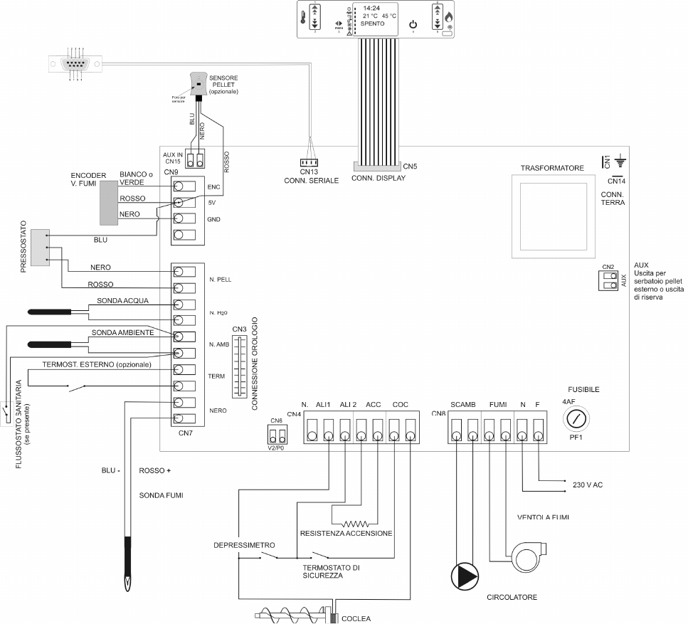
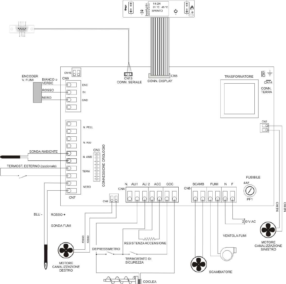
2.5 Electrical diagrams ............................................................................................................ 8
2.5.1 Hydro stoves and boilers ................................................................................................... 8
2.5.2 Air /Channelled Air........................................................................................................... 10
3
FUEL ........................................................................................................................ 11
3.1 General notes .................................................................................................................. 11
4
INSTALLATION ........................................................................................................ 12
4.1 General notes .................................................................................................................. 12
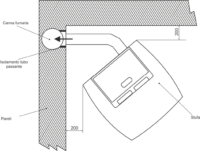
4.2 Minimum safety distances ............................................................................................... 12
4.2.1 Corner installation (mm) .................................................................................................. 12
4.2.2 Wall installation (mm) ...................................................................................................... 13
4.2.3 Distance from flammable ceilings and false ceilings (mm) ............................................... 14
4.2.4 Distance of fume exhaust system from flammable walls (mm) ......................................... 14
4.3 Flooring protection ........................................................................................................... 15
4.4 Minimum distances for positioning air intake vents .......................................................... 15
4.5 Fume exhaust duct .......................................................................................................... 16
4.5.1 General notes .................................................................................................................. 16
4.5.2 Tubes and maximum usable lengths ............................................................................... 16
4.5.3 Holes for exhaust tube passage on walls or roof: recommended insulation and diameter 17
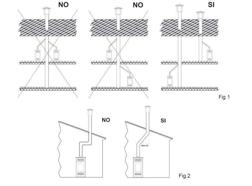
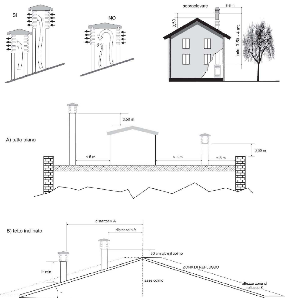
4.5.4 Using a traditional type chimney flue ............................................................................... 17
4.6 Using an external fume duct ............................................................................................ 18
5
ASSEMBLY .............................................................................................................. 19
5.1 General notes .................................................................................................................. 19
5.2 Unpacking ....................................................................................................................... 19
5.3 Electrical connection ........................................................................................................ 19
5.4 Water connection (only for hydro and boiler models) ....................................................... 20
5.5 Heating stove hydraulic diagram (only for hydro and boiler models) ................................ 20
5.5.1 Indicative hydraulic diagram heating only (only for hydro and boiler models) ................... 21
5.6 External thermostat installation ........................................................................................ 21
5.7 Remote control ................................................................................................................ 21
6
USE .......................................................................................................................... 22
6.1 Console description ......................................................................................................... 23
6.2 First ignition ..................................................................................................................... 25
6.3 Ignition and normal operation .......................................................................................... 25
6.3.1 Stove start-up .................................................................................................................. 25
6.3.2 No start-up ...................................................................................................................... 26
6.3.3 Normal Operation ............................................................................................................ 27
6.3.4 Modulation based on room temperature (all models) ....................................................... 28
6.3.5 Modulation based on boiler water temperature (Hydro stoves and boilers only) .............. 28
6.3.6 Ventilation (air and channelled air models) ...................................................................... 28
6.3.7 Circulator (hydro and boiler models) ................................................................................ 29
6.3.8 External thermostat ......................................................................................................... 29
6.3.9 Brazier cleaning ............................................................................................................... 29
6.3.10 Shutdown .................................................................................................................. 29
6.3.11 Interruption of power supply ....................................................................................... 30
6.3.12 Remote control. ......................................................................................................... 30
7
MENU ....................................................................................................................... 31
7.1 Menu 01 "WATER PRESSURE" ...................................................................................... 31
Menu 01 "FANS ADJUSTMENT" .............................................................................................. 31
7.2 Menu 02 "CLOCK SET" ................................................................................................... 32
7.3 Menu 03 "CHRONO SET" ............................................................................................... 32
7.3.1 Menu 3-1 “ENABLE CHRONO” ....................................................................................... 32
7.3.2 Menu 3-2 “DAILY PROGRAMME................................................................................... 33
7.3.3 Menu 3-3 “WEEKLY PROG-“ .......................................................................................... 33
7.3.4 Menu 3-4 “WEEKEND PROG-“ ....................................................................................... 35
7.4 Menu 04 "CHOOSE LANGUAGE" ................................................................................... 35
7.5 Menu 05 "STAND-BY MODE" ......................................................................................... 36
7.6 Menu 06 "BUZZER MODE" ............................................................................................. 36
7.7 Menu 07 "INITIAL LOAD" ................................................................................................ 36
7.8 Menu 08 “STOVE STATUS” ............................................................................................ 36
7.9 Menu 09 “TECHNICAL CALIBRATIONS” ........................................................................ 37
7.10 Menu 10 “PELLET TYPE” (only specially designed models) ............................................ 37
7.11 Menu 11 “FIREPLACE TYPE” (only specially designed models) ..................................... 37
7.12 Menu 12 “FAN” (only specially designed models) ............................................................ 37
8
SAFETY and ALARMS ............................................................................................ 38
8.1 Safety devices ................................................................................................................. 38
8.1.1 Fume exhaust pressure sensor ....................................................................................... 38
8.1.2 Boiler /structure temperature sensor ................................................................................ 38
8.1.3 Smoke temperature sensor ............................................................................................. 39
8.1.4 Water temperature sensor ............................................................................................... 39
8.1.5 Water pressure switch ..................................................................................................... 40
8.2 Alarms ............................................................................................................................. 41
9
WARNINGS AND MAINTENANCE .......................................................................... 43
9.1 Opening the door ............................................................................................................. 43
9.2 Disposal of ashes ............................................................................................................ 43
9.3 Brazier cleaning ............................................................................................................... 43
9.4 Ash drawer cleaning ........................................................................................................ 43
9.5 Combustion chamber cleaning ........................................................................................ 43
9.6 Smoke chamber cleaning ................................................................................................ 43
9.7 Exhaust system cleaning ................................................................................................. 43
9.8 Cleaning metal and ceramic parts ................................................................................... 44
9.9 Cleaning glass ................................................................................................................. 44
9.10 Broken glass.................................................................................................................... 44
9.11 Replacing the remote control battery ............................................................................... 44
9.12 Cleaning fans .................................................................................................................. 44
9.13 Stove inactivity ................................................................................................................ 44
9.14 Routine and special maintenance .................................................................................... 44
1 GENERAL STANDARDS
In general, refers to regulations concerning "heat generators fed with wood and other solid fuels",
UNI 10683:2005.
1.1 Fireplace or Chimney flue
Each device must have a vertical duct, called a chimney flue, for outside release of combustion
fumes produced by a natural draft.
The chimney flue must meet the following requirements:
-It should not be connected to any other fireplace, stove, boiler, or hood of any kind (Fig. 1).
-It must be properly spaced from combustible or flammable materials through an air gap or suitable
insulating material.
-The internal section must be uniform, preferably circular: the square or rectangular sections must
have rounded corners with a radius of no less than 20 mm, maximum ratio between the sides of 1.5,
walls as smooth as possible and without restrictions, curves must be regular and seamless,
deviations from the axis no greater than 45° (Fig-2).
-Each device must have its own chimney flue with a section equal to or greater than the diameter of
the fume exhaust pipe of the stove and a height no less than the one stated (see table 2).
-Never use two stoves, a fireplace and a stove, a stove and a wood stove, etc. in the same room
since the draft of one could damage the draft of the other. In addition, collective ventilation ducts that
can cause a vacuum in the installation environment are not permitted, even if installed in adjacent
rooms and communicating with the installation room.
-Creating fixed or mobile apertures on the chimney flue to connect equipment other than auxiliary
devices is prohibited.
-Passing other air supply channels and piping for utilities through the chimney flue, however large,
is prohibited.
-The chimney flue should be equipped with a collection chamber for solid materials and any
condensate, located below the mouth of the flue, so as to be easily opened and inspected from an
airtight door.
-Whenever using parallel output chimneys, it is advisable to raise a bracing element. (Fig.3)
1.2 Chimney pot
The top of the chimney flue must be equipped with a device, called a chimney pot, which facilitates
dispersion into the atmosphere of combustion products.
The chimney pot must meet the following requirements:
- Its internal section and shape must be equivalent to that of the chimney flue.
- Have a useful outlet section no less than double that of the chimney flue.
- Chimney pots that emerges from the roof or which remain in contact with the outside (for example
in the case of an open loft), must be covered with brick elements and well isolated. It must be
constructed so as to prevent penetration into the flue of rain, snow, or foreign bodies and so that, in
the event of winds in any direction and at any angle, it assures the discharge of combustion products
(windproof chimney pot).
-The chimney pot must be positioned so as to guarantee an adequate dispersion and dilution of
combustion products and, in any case, outside the zone of reflux. This zone can be different sizes
and shapes depending on the angle of slope of the roof, so it is necessary to adopt the minimum
heights shown in Fig.4 and Fig.5.
- The chimney pot must be of windproof and exceed the height of the ridge, Fig.4 and Fig.5.
-Any buildings or other obstacles that exceed the height of the chimney pot must not be close to the
chimney pot itself (Fig.4).
Fig.3 Fig.4
Fig. 5
Table 2
Roof pitch ? [°]
Horizontal width of
the zone of reflux
from the axis of the
ridge A[m]
Minimum height of
the outlet from the
roof Hmin
=Z+0.50m
Height of the reflux
zone Z [m]
15 1.85 1.00 0.50
30 1.50 1.30 0.80
45 1.30 2.00 1.50
60 1.20 2.60 2.10
1.3 External air intake vent
-The stove must have the air necessary to ensure smooth combustion operation and good
environmental well-being.
-Make sure that the room where the stove is installed offers sufficient ventilation and install an air
supply duct from the outside with the recommended minimum section of 100 cm².
-The air intake vent must communicate directly with the installation room of the stove, positioned so
as to prevent it from being blocked and protected with a permanent non-lockable grid or other
suitable protection provided that it does not reduce the minimum section.
-Air flow can also be obtained from a room adjacent to the installation room, provided that this flow
can be carried out freely through permanent, non-closable openings communicating with the outside.
-With respect to the installation room, the adjacent room should not be put under vacuum with
respect to the external environment as a result of a reverse draft caused by the presence in this
space of another utility device or suction device. The room adjacent to the permanent openings must
meet the requirements set out in the paragraphs above. The adjacent room cannot be used as a
garage, for storage of combustible material or for activities involving a risk of fire.
1.4 Connection to the chimney flue
(see paragraph 4.5)
1.5 Preventing house fires
Installation and use of the stove must be in accordance with the manufacturer's instructions and with
local habitability regulations.
CAUTION: when a fume exhaust pipe passes through a wall or ceiling, particular installation methods
must be applied (protection, thermal insulation, distances from heat sensitive materials, etc.).
- The fireplace connecting tube must never pass through a combustible surface.
- Do not connect this unit to a chimney flue already being used by another device.
-It is also advisable to maintain all combustible elements or flammable material such as beams,
wooden furniture, curtains, flammable liquids, etc. outside the radiation area of the furnace and at
a distance of at least 1 m from the heating block. .
-In the event that the surrounding space has coverings in combustible or heat-sensitive material, a
protective membrane made of non-combustible insulating material must be interposed. If the flooring
is made of combustible material, a non-combustible protective material that protrudes laterally and
frontally from 15cm to 30 cm must be provided at the mouth of the furnace.
- For further information, refer to local requirements.
2 SPECIFICATIONS AND TECHNICAL DATA
2.1 Specifications
Stoves and pellet stoves are devices built to work with good quality wood pellets only (see par. 3
fuel). Hydro models must be connected to the plumbing system.
2.2 Technical data
(see attached sheet)
2.3 Rear connection dimensions
(see attached sheet)
2.4 Product identification data
(see attached sheet)
The technical label shows device data and performance. Tampering with, removing or lack of a
technical label makes installation and maintenance operations difficult, due to the lack of product
identification. In the event of damage, request a duplicate from our service centre. Given the
importance of the data label, we recommend installing the stove at a distance at which it is always
visible.
2.5 Electrical diagrams
2.5.1 Hydro stoves and boilers
2.5.2 Air /Channelled Air
3 FUEL
3.1 General notes
The pellet stove is designed to burn wood pellets only.
Wood pellets are a fuel obtained from the pressing of sawdust timber, extracted from the processing
and transformation residues of dried wood material. The compactness of the product over time is
guaranteed by a natural origin substance contained in the wood: lignin. The typical small cylinder
form is obtained by extrusion.
Various types of pellets with quality and characteristics that vary depending on the processing and
type of wood species used are available on the market.
CAUTION: Always use certified quality wood pellets: i.e. DIN, DIN PLUS, ÖM 7135, Pellet
Gold, Catas etc. The company does not guarantee proper stove functioning with the use of
low quality pellets.
Stoves and heating stoves are tested and programmed to ensure good performance and perfect
quality operation with specific characteristic pellets:
components:
wood
length:
< 30 mm
diameter:
6-6.5 mm
lower calorific value:
4.8 kWh/kg
humidity rate:
< 8 %
residual ash:
< 0.5 %
GOOD QUALITY pellets are smooth, shiny, slightly dusty and with regular length.
LOW QUALITY pellets are of varied lengths, dusty with vertical and horizontal splits.
Since pellet characteristics and quality greatly influence the autonomy, efficiency and
proper operation of the stove, we recommend:
AVOID using pellets with dimensions different from that described by the manufacturer.
AVOID using low quality pellets or pellets containing dispersed sawdust powder, resins or
chemicals, additives or adhesives.
AVOID using moist pellets.
The use of unsuitable pellets causes:
- clogging of the brazier and fume discharge ducts
- increased consumption of fuel
- decreased efficiency
- no guarantee of normal stove operation
- dirtying of glass
- production of unburned granules and heavy ash
The presence of moisture in pellets increases the volume of the capsules and crumbles, causing
- feeding system malfunctions
- poor combustion
Pellets should be stored in a dry and sheltered place. Particular attention should be given to the
handling of the bags to prevent their crushing, resulting in the formation of sawdust.
Stove operation parameters may have to be altered when using quality pellets with dimensional and
calorific characteristics different from those indicated. Contact an authorised service centre if
necessary.
THE USE OF POOR QUALITY PELLETS NOT IN ACCORDANCE WITH MANUFACTURER'S
INSTRUCTIONS NOT ONLY DAMAGE THE STOVE AND COMPROMISE PERFORMANCE BUT
MAY RESULT IN FORFEITURE OF THE WARRANTY AND COMPANY LIABILITY.
4 INSTALLATION
4.1 General notes
Installation of stoves in bedrooms, bathrooms, or
in places where there is another heating appliance that does not have its own appropriate
air flow (chimney, stove, etc.), outside exposed to the weather or in wet areas is prohibited.
Stove installation must be carried out in a location which allows safe and easy use and
simple maintenance. Said location must also be equipped with electrical grounding as required by
law.
The external air intake vent must meet the requirements of paragraphs 1.3 and 4.4.
CAUTION: ensure that the plug for electrical connection remains accessible after stove installation.
4.2 Minimum safety distances
The following figures show the minimum safety distances which must always be guaranteed.
4.2.1 Corner installation (mm)
13


Need help? Post your question in this forum.

Forumrules


Report abuse

Libble takes abuse of its services very seriously. We're committed to dealing with such abuse according to the laws in your country of residence. When you submit a report, we'll investigate it and take the appropriate action. We'll get back to you only if we require additional details or have more information to share.

Product:

For example, Anti-Semitic content, racist content, or material that could result in a violent physical act.

For example, a credit card number, a personal identification number, or an unlisted home address. Note that email addresses and full names are not considered private information.

Forumrules

To achieve meaningful questions, we apply the following rules:

Register

Register getting emails for Eva Calor Tosca 15 kW at:


You will receive an email to register for one or both of the options.


Get your user manual by e-mail

Enter your email address to receive the manual of Eva Calor Tosca 15 kW in the language / languages: English as an attachment in your email.

The manual is 5,06 mb in size.


You will receive the manual in your email within minutes. If you have not received an email, then probably have entered the wrong email address or your mailbox is too full. In addition, it may be that your ISP may have a maximum size for emails to receive.

Others manual(s) of Eva Calor Tosca 15 kW

Eva Calor Tosca 15 kW User Manual - German - 38 pages

Eva Calor Tosca 15 kW User Manual - Dutch - 90 pages


The manual is sent by email. Check your email

If you have not received an email with the manual within fifteen minutes, it may be that you have a entered a wrong email address or that your ISP has set a maximum size to receive email that is smaller than the size of the manual.

The email address you have provided is not correct.

Please check the email address and correct it.

Your question is posted on this page

Would you like to receive an email when new answers and questions are posted? Please enter your email address.


Info