15
14
General
The fitting of the appliance should only be
carried out by a registered Corgi gas fitter.
Please note:
This appliance is not connected to a flue duct.
Take care to ensure that there is sufficient
ventilation.
Electrical connection
230 V - 50 Hz.
This appliance complies the regulations
concerning electromagnetic compatibility in
directive 89/336/EEC.
■ The electrical connection must comply with
national and local regulations.
■ Wall socket and plug must be accessible at
all times.
■ If you want to make a fixed connection,
ensure that a multi-pole switch with a
distance between contacts of 3 mm is
installed in the supply cable.
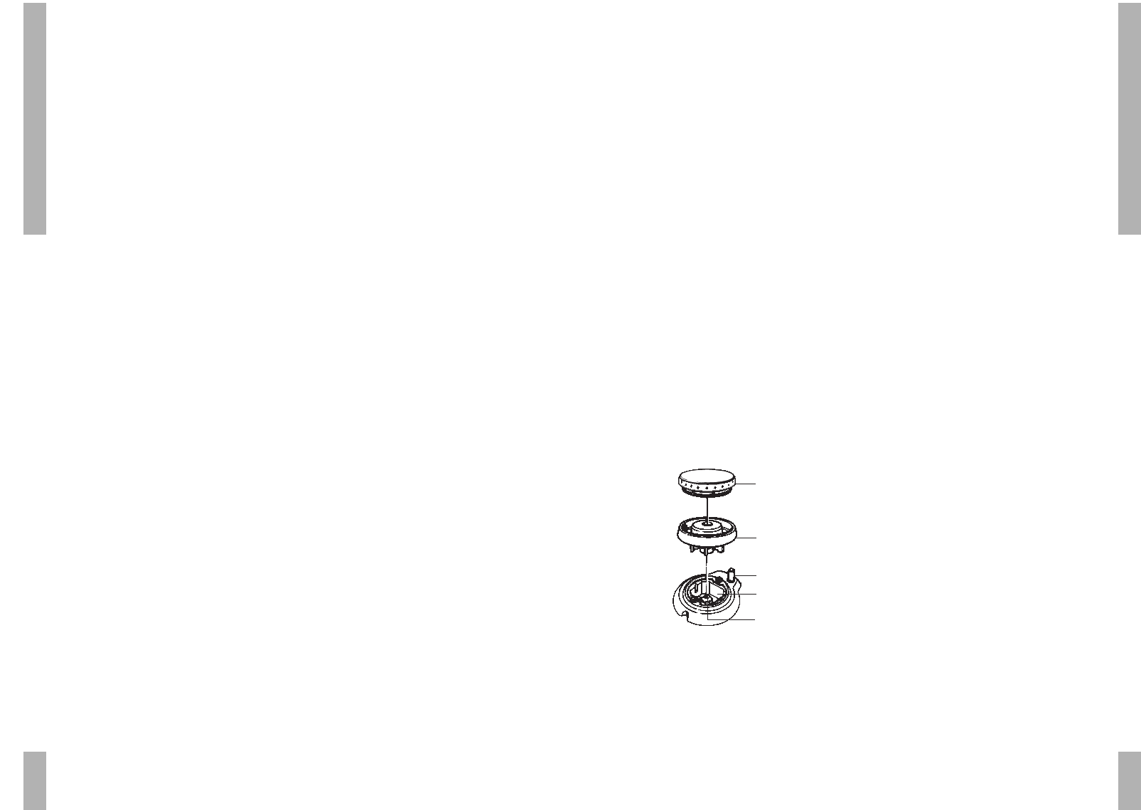
Gasconnection RC 1/2˝ (ISO 7/1-RC 1/2)
■ The gas connection must comply with
national and local regulations.
Amongst other things these regulations
instruct that:
– only approved materials are to be used;
– only a completely metal hose may be used
behind a built-in oven and beneath the hob.
Please note:
The type of gas and the country for which the
appliance has been designed are indicated on
the data badge.
■ We recommend that the hob be connected by
means of a fixed pipe. Connection using a
specially designed safety hose is also
permitted. In all cases the connection tap for
the appliance must be positioned such that it
is easily accessible, in an adjacent kitchen
cupboard, for example.
Please note:
A metal safety hose must not get kinks in it or get
trapped and must not come into contact with
moving parts of the kitchen furniture.
■ Before using the appliance for the first time
check the connections using water and
washing-up liquid to ensure that there are no
gas leaks.
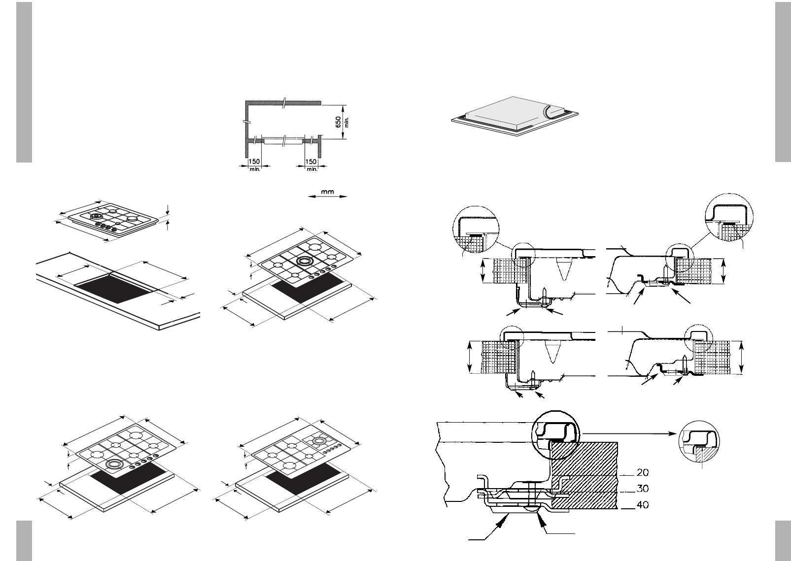
■ Do not install a hob next to a high cupboard
or wall made of flammable material. (If there
is no alternative, ensure that there is a
minimal distance of 150 mm between the
outer edge of the hob and the wall in
question. Also ensure that there is a minimum
distance of 650 mm between the hob and any
overhead extractor fan which may be
installed.)
INSTALLATION
USE/MAINTENANCE
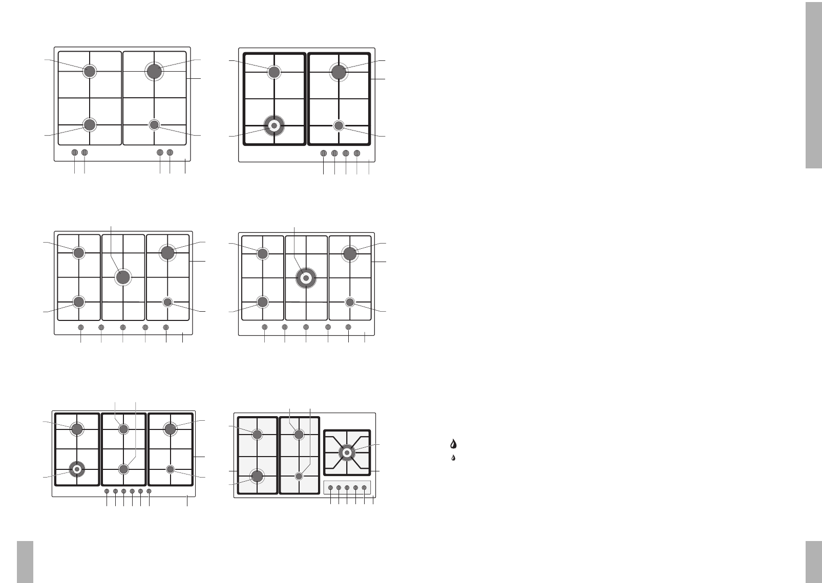
Saucepans
The recommended saucepan diameters are:
rapid burner . . . . . . . . . . . . . . . . minimum 24 cm.
semi-rapid burner . . . . . . . . . . . minimum 20 cm.
simmer burner . . . . . . . . . . . . . . minimum 12 cm.
wok burner . . . . . . . . . . . . minimum 24 - 26 cm.
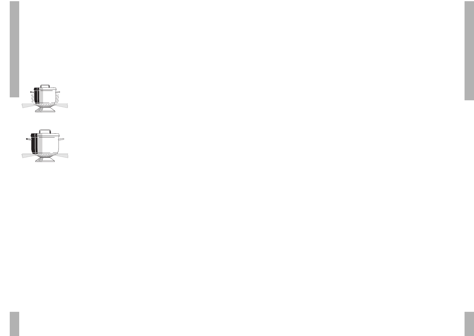
Wrong:
A great deal of heat is
lost along the sides of
the saucepan.
Right:
The heat is evenly
distributed over the
base of the saucepan.
Tip:
Cooking with a lid on the pan saves up to 50%
on energy.
Clean saucepans absorb heat more efficiently.
Cleaning the appliance
■ Clean the appliance daily with water and a
detergent or all purpose cleaner. Avoid
using too much water to prevent it entering
the burner or ventilation openings.
■ Remove stubborn stains on enamel with a
non-abrasive cream or a soft sponge.
Never use scouring powders, aggressive
cleaning agents, green scours.
■ Remove stubborn stains on stainless steel
with a special stainless-steel cleaning
agent. Always polish in the direction of the
surface structure of the stainless steel. In
this way, you will prevent shiny patches
occurring.
If stains cannot be removed, clean the hob
with the proprietary HG oven & grill cleaner.
Always treat the whole drip-tray, to prevent
"colour differences". Always treat with a
stainless-steel polish / care product
afterwards.
■ Scourers contain abrasives that cause
scratches on stainless steel. The stainless
steel has a surface structure. Scouring or
polishing will cause (shiny) patches on the
surface. This damage is excluded from the
guarantee.
Please note:
Do not drop hot burner caps in cold water.
Because of the strong cooling they might get
damaged.