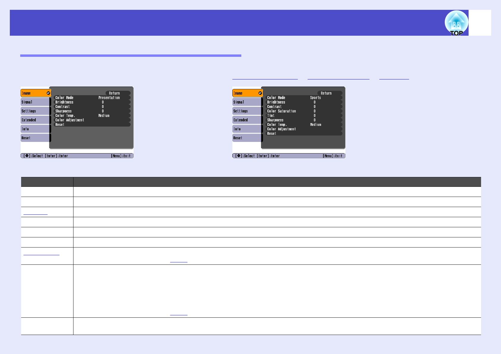
The items that can be set will vary depending on the input source that is currently being projected. Setting details are saved separately for each source.
Sub-menuFunction
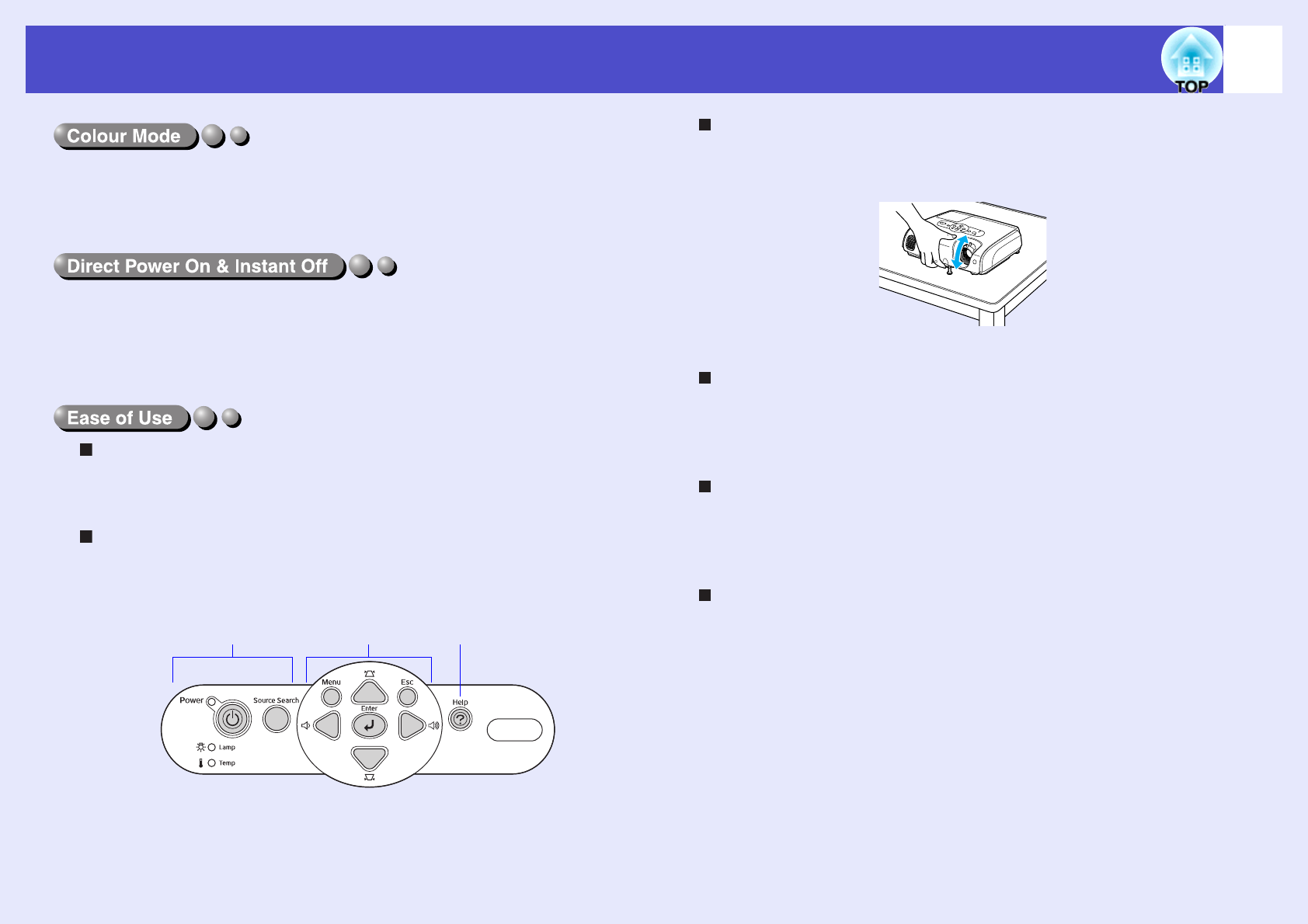
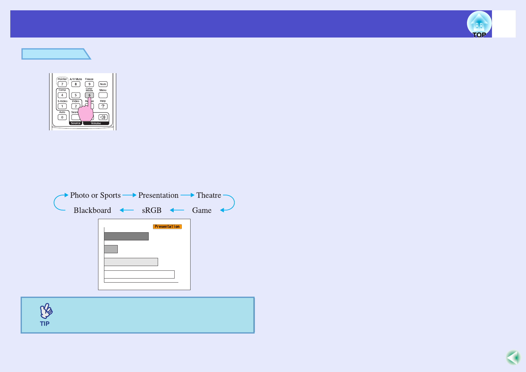
Color ModeSelect the quality of the image to suit your surroundings. sp.15
BrightnessAdjusts the image brightness.
ContrastgAdjusts the difference between light and shade in the images.
Color SaturationAdjusts the colour saturation for the images.
Tint(Adjustment is only possible when component video or NTSC signals are being input.) Adjust the image tint.
SharpnessAdjusts the image sharpness.
Color Temp.g
(EMP-X3 only)
You can adjust the overall tint of images. If you select "High", images appear bluish, and if you select "Low", images appear reddish.
(This item cannot be selected if "sRGBg" has been selected as the "Color Mode" setting in the "Image" menu.)
Color
Adjustment
Adjusts the red, green, and blue colour strength of the image.
Abs. Color Temp.: You can adjust the overall tint of images. You can adjust tints in 10 stages from 5000 K to 10000 K. (EMP-82/62 only)
Red: Adjust the saturation of the red component.
Green: Adjusts the saturation of the green component.
Blue: Adjusts the saturation of the blue component.
(This item cannot be selected if "sRGBg" has been selected as the "Color Mode" setting in the "Image" menu.)
ResetResets all adjustment values for the "Image" menu functions to their default settings.
If you would like to return all menu items to their default, see "Reset All". sp.40
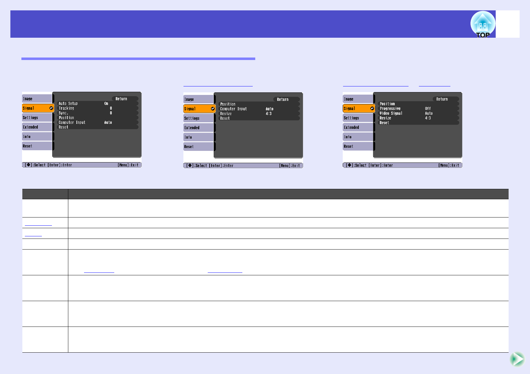
The items that can be set will vary depending on the input source that is currently being projected. Setting details are saved separately for each source.
Sub-menuFunction
Auto SetupSelects whether the automatic adjustment function for automatically optimising images when the input source is changed is turned "On" or
"Off". sp.13
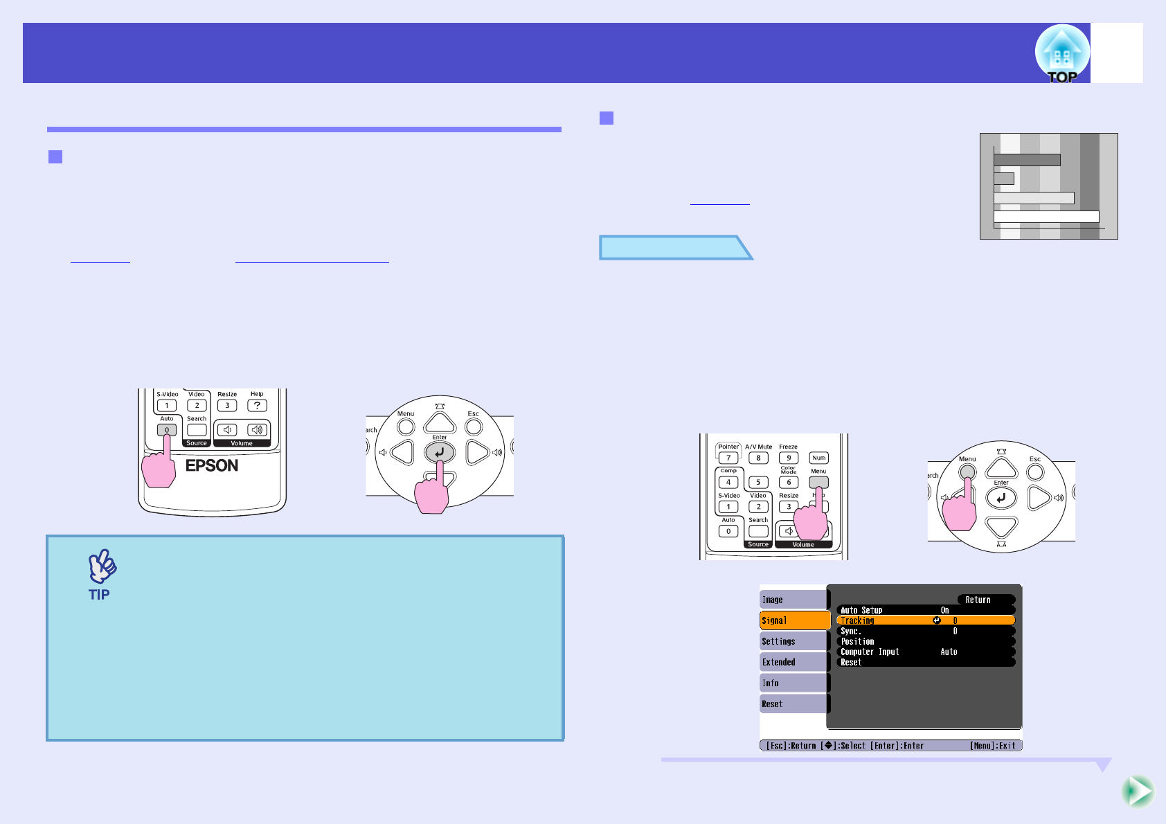
TrackinggAdjusts computer images when vertical stripes appear in the images. sp.13
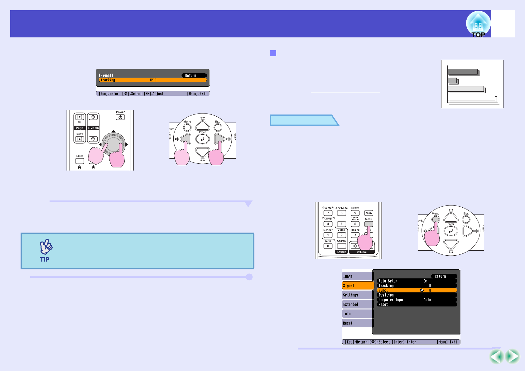
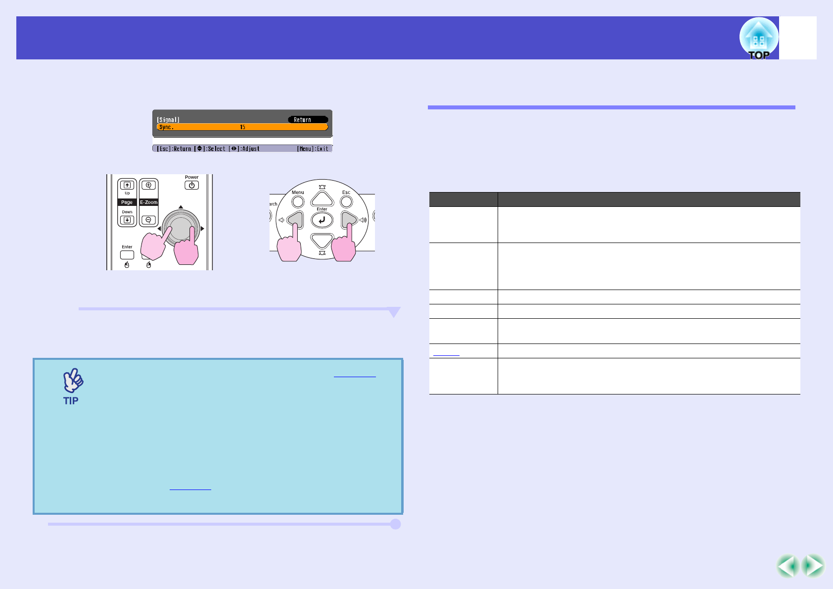
Sync.gAdjusts computer images when flickering, fuzziness or interference appear in the images. sp.14
PositionMoves the image display position vertically and horizontally.
Progressive(Adjustment is only possible when composite Video or S-Video signals are being input.)
Off: IP conversion is carried out for each field in the screen. This is ideal for using when viewing images with a large amount of movement.
On: Interlacedg (i) signals are converted into progressiveg (p) signals. This is ideal for using when viewing still images.
Computer
Input (EMP-
X3 only)
Selects the input signal in accordance with the equipment that is connected to the Computer port.
If set to "Auto" the input signal is set automatically in accordance with the connected equipment.
If the colours do not appear correctly when you select "Auto", select the appropriate signal for the connected equipment manually.
Computer1
Input (EMP-
82/62 only)
Selects the input signal in accordance with the equipment that is connected to the Computer1 port.
If set to "Auto" the input signal is set automatically in accordance with the connected equipment.
If the colours do not appear correctly when you select "Auto", select the appropriate signal for the connected equipment manually.
Computer2
Input (EMP-
82/62 only)
Selects the input signal in accordance with the equipment that is connected to the Computer2 port.
If set to "Auto" the input signal is set automatically in accordance with the connected equipment.
If the colours do not appear correctly when you select "Auto", select the appropriate signal for the connected equipment manually.
Video Signal(Adjustment is only possible when composite video/S-Video signals are being input.)
Sets the video signal format.
With the "Auto" function, image signals are recognized automatically. If interference appears in the projected images or no images appear when
you select "Auto", select the appropriate signal manually.
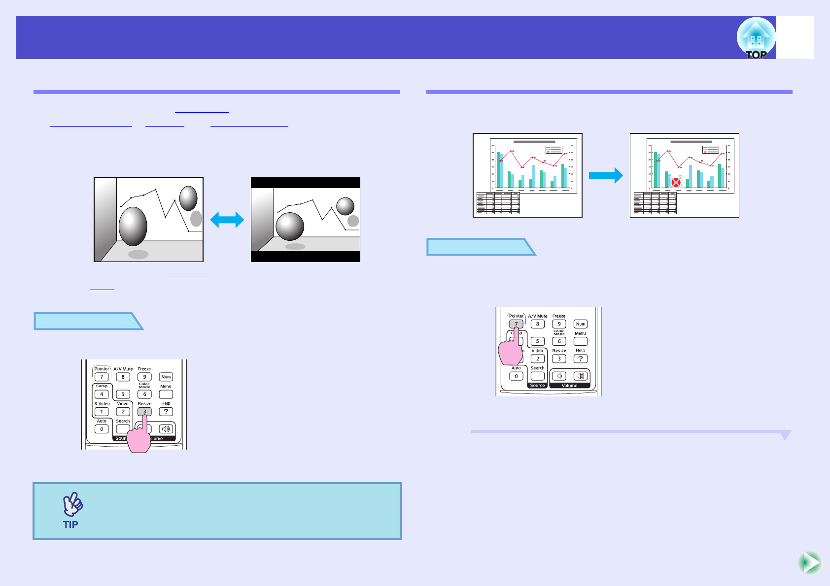
ResizeSets the aspect ratiog for projected images. sp.21
ResetResets all adjustment values on the "Signal" menu to their default settings, except "Computer Input", "Computer1 Input", and "Computer2
Input".
If you would like to return all menu items to their default, see "Reset All". sp.40
Sub-menuFunction
36
List of Functions
"Settings" Menu
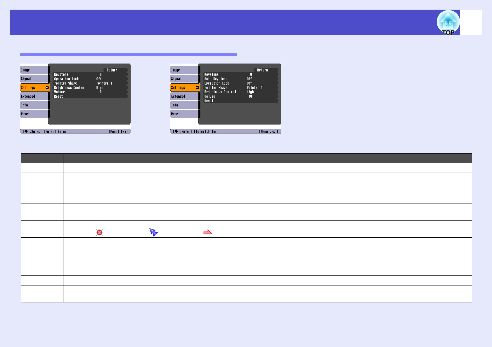
Sub-menuFunction
KeystoneCorrects vertical keystone distortion in images. sp.i
Auto
Keystone
(EMP-82/62
only)
Sets the function for automatically detecting the projector angle and correcting keystone "On" or "Off" when the projector is tilted vertically.
This function is only enabled when the "Projection" command in the "Extended" menu is set to "Front". If it is set to something other than
"Front", this menu cannot be selected.
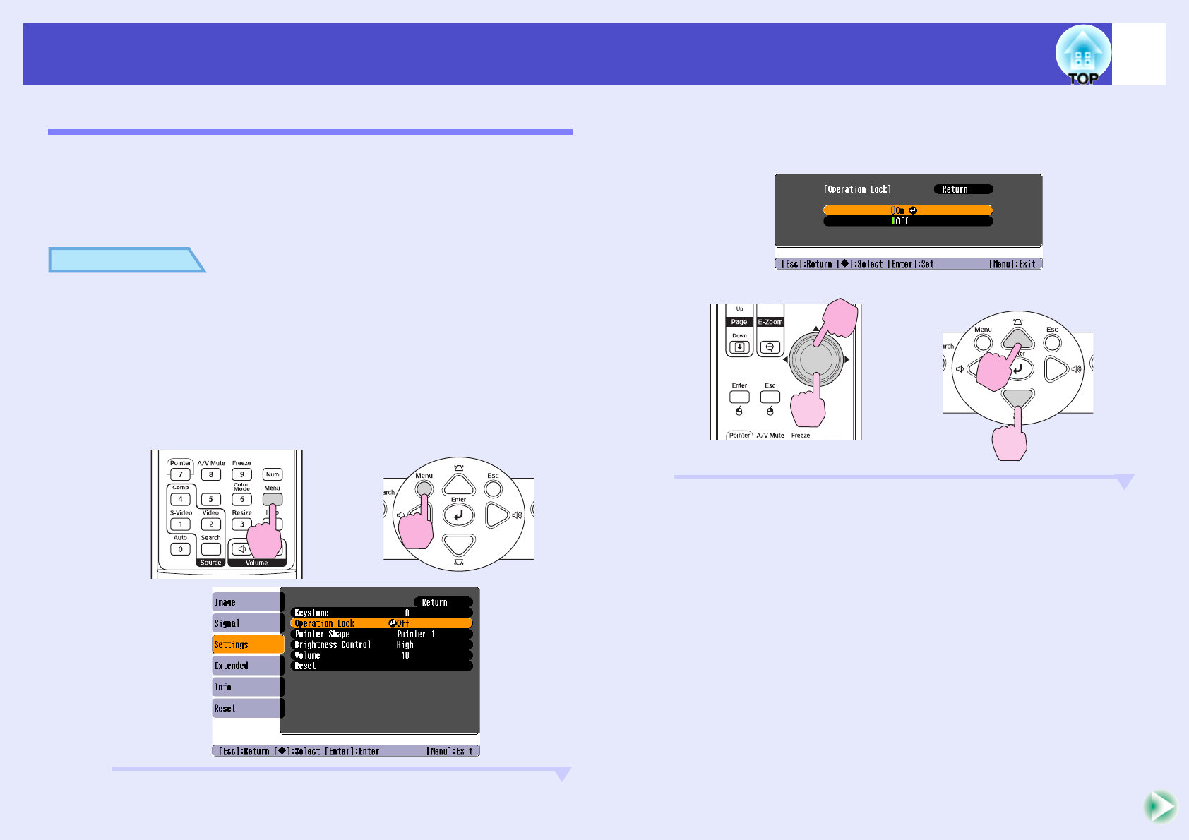
Operation
Lock
When set to "On", the operation of all buttons on the projector's control panel except for the [Power] button will be disabled. sp.29
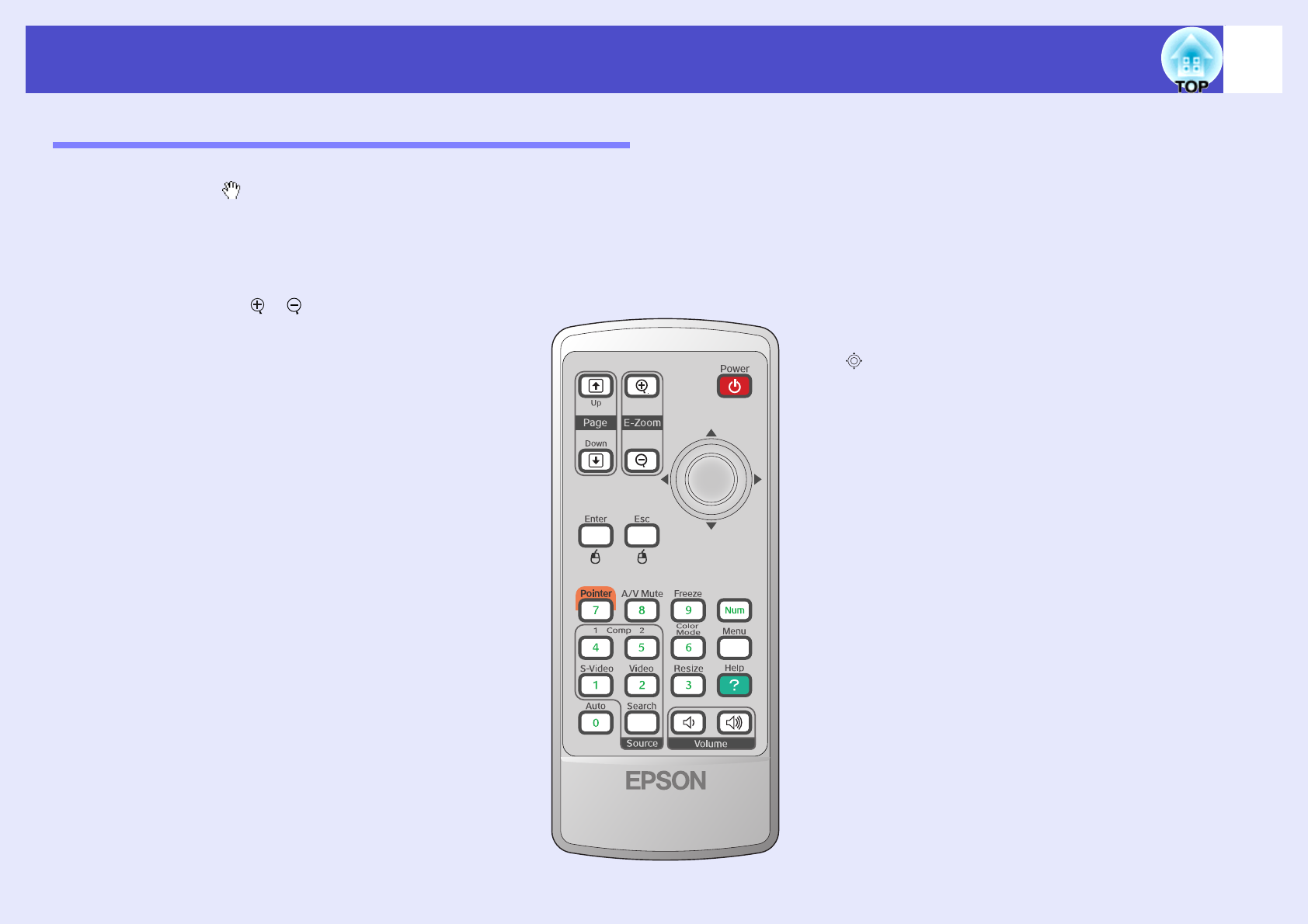
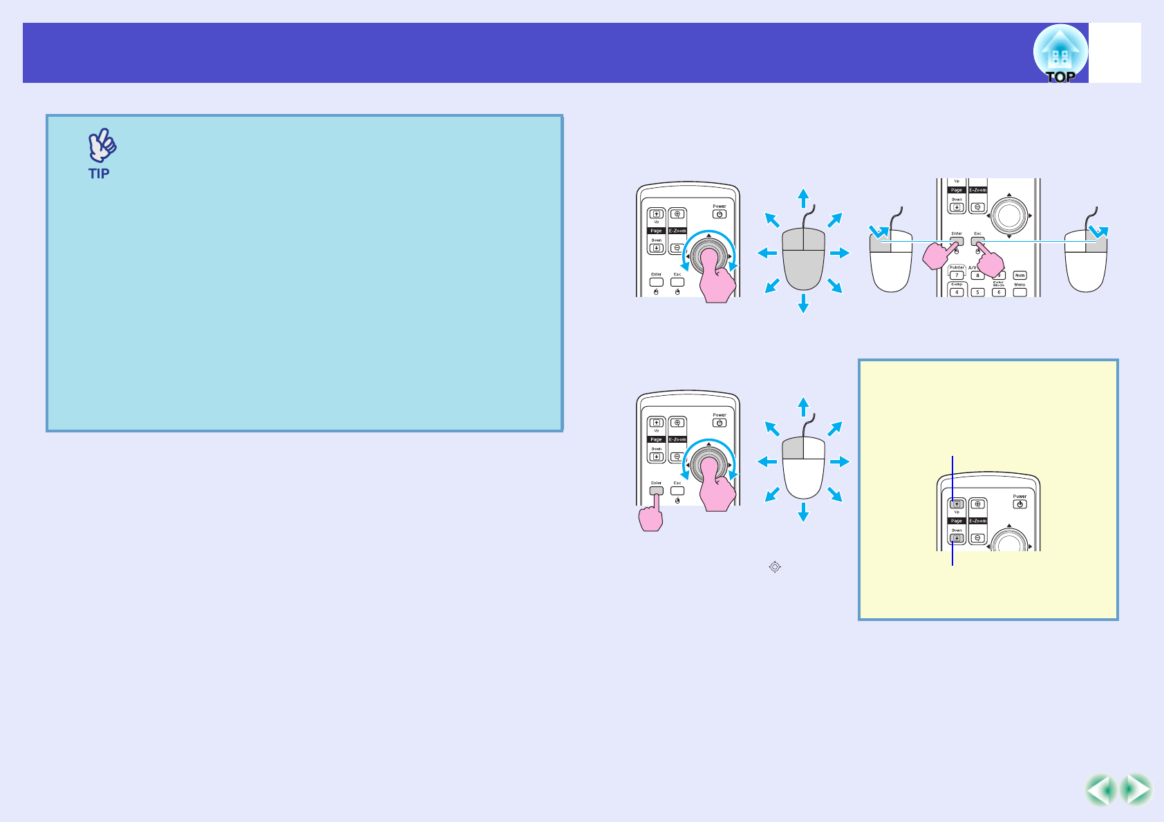
Pointer
Shape
The shape of the pointer can be selected. sp.21
Pointer 1: Pointer 2: Pointer 3:
Brightness
Control
This lets you set the lamp brightness to one of two settings.
Select "Low" if the images being projected are too bright such as when projecting images in a dark room or onto a small screen.
When "Low" is selected, the brightness of the images is reduced, the amount of electricity consumed and noise produced during projection are
reduced, and the lamp's operating life is extended. Also the fan noise is reduced. (Electrical consumption: about an 35 W decrease, lamp life:
about 1.5 times longer, Fan noise: about 20% reduction)
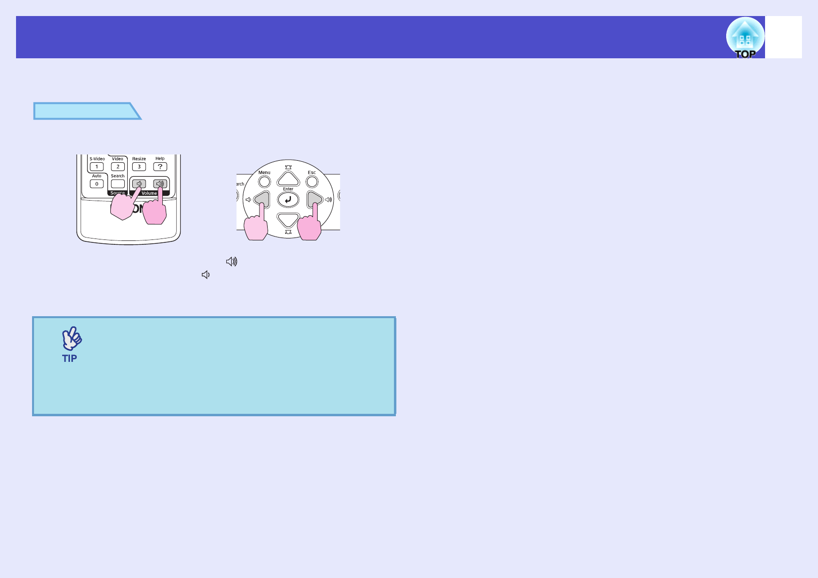
Vo l umeAdjusts the volume. sp.17
ResetResets all adjustment values on the "Settings" menu to their default settings.
If you would like to return all menu items to their default, see "Reset All". sp.40
Screen shot from EMP-X3Screen shot from EMP-82/62
37
List of Functions
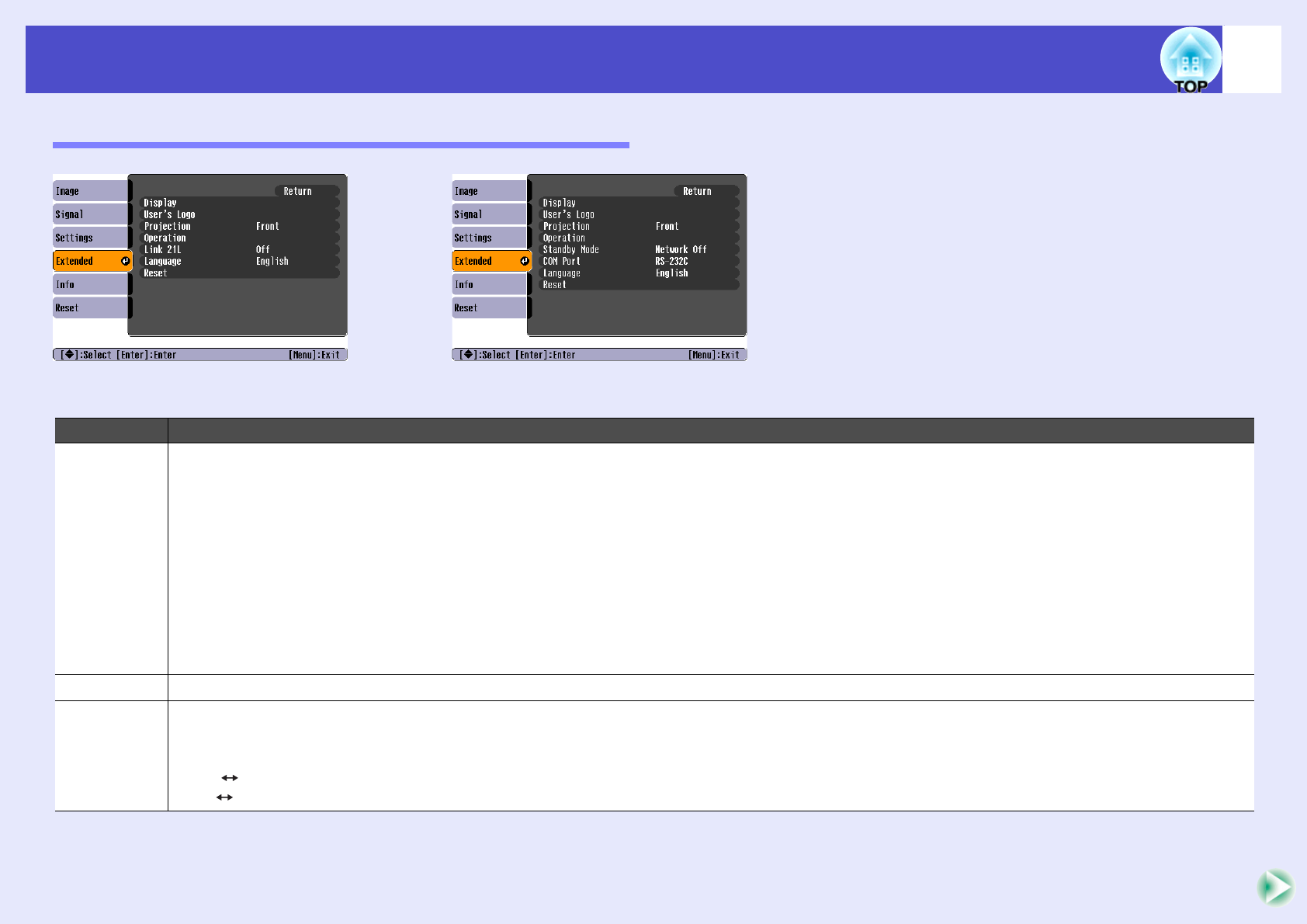
"Extended" Menu
Sub-menuFunction
DisplayThis lets you make settings related to the projector's display.
Message:
Sets whether the input source name or colour mode name or a message is displayed on the screen ("On") or not displayed ("Off") at times such
as when the input source or colour mode is changed or when no image signals are being input.
Display Background:
Sets the screen status to "Black", "Blue", or "Logo" when no image signals are being input.
Startup Screen:
The startup screen (the image projected when starting the projector) is displayed when starting (On)/ or not displayed when starting (Off). The
setting is enabled after turning the power supply off and then back on.
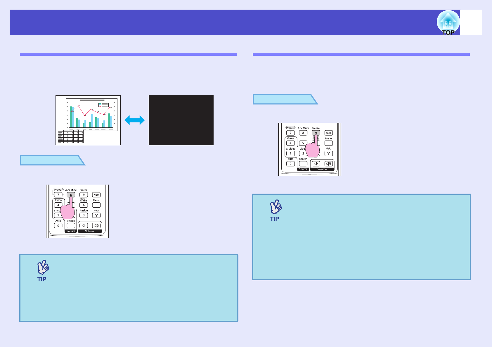
A/V Mute:
You can choose the Screen display in A/V mute from "Black", "Blue", and "Logo".
User’s LogoChange the user's logo that is displayed as a background and displayed during A/V Mute. sp.64
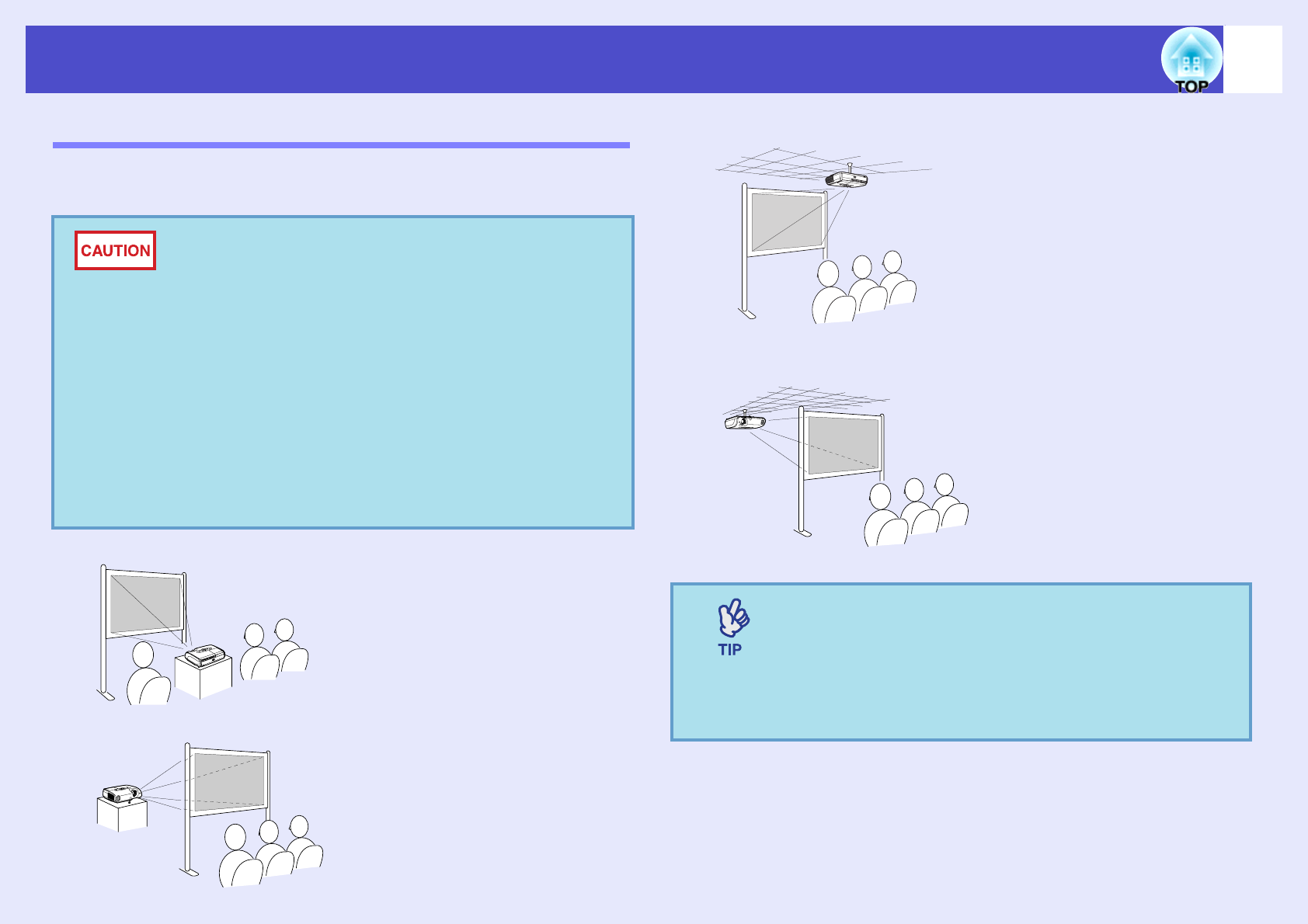
ProjectionSets the projection position for the projector. sp.56
"Front" "Front / Ceiling" "Rear" "Rear / Ceiling"
By holding down the [A/V Mute] button for about 5 seconds, you can change the projection setup in the following ways.
Front Front Ceiling
Rear Rear Ceiling
Screen shot from EMP-X3Screen shot from EMP-82/62
38
List of Functions
OperationDirect Power On:
Sets whether direct power on is enabled ("On") or disabled ("Off").
When you set to "On" and leave the power cable connected to a wall socket, be aware of that sudden surges of electricity that may occur when
power comes back on after a power outage may cause the projector to turn on automatically.
Sleep Mode:
Sets whether projection stops automatically ("On") or not ("Off") when no operations are carried out for approximately 30 minutes while no
image signals are being input.
High Altitude Mode:
When using above an altitude of about 1500m, set to "On".
Link 21L
(EMP-X3
only)
Sets whether the EMP Link 21L utility software is being used or not.
To enable the EMP Link 21L, turn the projector's power off and wait until the cool down period has finished.
Standby
Mode
(EMP-82/62
only)
Set to "Network On" to use network monitoring and control functions and the standby monitor out function while the projector is in standby
mode.
If you change the setting, the new setting will be enabled after the power is turned off.
•We provide softwares* for network monitoring and controlling projectors.
•When set to "Network On", the Power indicator will flash orange and then remain orange after disconnecting the power plug and reinserting it
into the electrical outlet.
COM Port
(EMP-82/62
only)
This can be set to either "RS-232C" or "USB", depending on the port that is being used for communication with a computer.
If you change the setting, the new setting will be enabled after the power is turned off.
LanguageSets the language for message displays.
ResetReturns "Display" and "Operation" settings in the "Extended" menu (except for "High Altitude Mode") to their default settings.
If you would like to return all menu items to their default, see "Reset All". sp.40
Sub-menuFunction
*EMP Monitor : Allows you to monitor multiple projectors on the network and control them all at once using functions such as turning the power on and off and
switching input sources.
For the detailed and current information about the software, please visit the following website.
http://esupport.epson-europe.com/downloads/en/
39
List of Functions
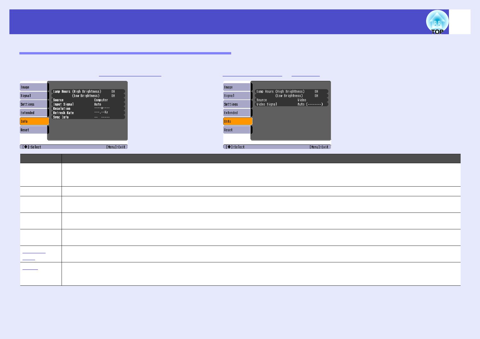
"Info" Menu
Lets you check the status of the image signals being projected and the status of the projector. (Display only)
Sub-menuFunction
Lamp HoursShows the cumulative lamp operating time.
If it reaches the lamp warning time, the characters are displayed in yellow. The cumulative operating time from 0 to 10 hours will be displayed as
"0H". From "10H" onwards, the display will be in units of 1 hour.
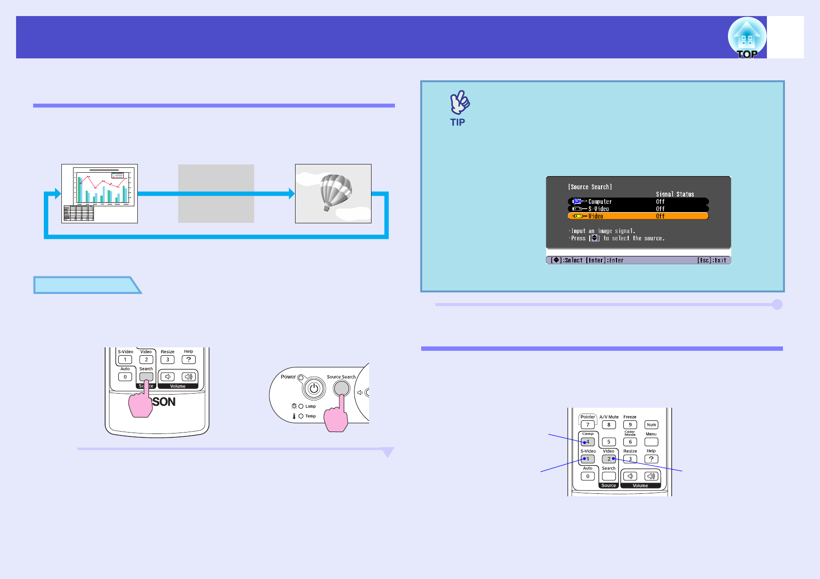
SourceDisplays the input source which is currently being projected.
Input SignalDisplays the input signal settings.
(Does not appear when the input source is composite video or S-video.)
ResolutionDisplays the input resolution.
(Does not appear when the input source is composite video or S-video.)
Video SignalShows the video signal format.
(Not displayed for computer, RGB video, or component video images.)
Refresh
Rateg
Displays the refresh rate.
(Does not appear when the input source is composite video or S-video.)
Sync.g InfoInformation from this menu may be required when you ask for service from your dealer or from the nearest address provided in the
"International Warranty Conditions" section of the Safety Instructions/World Wide Warranty Terms booklet.
(Does not appear when the input source is composite video or S-video.)
•Rear/ceiling projection using a translucent screen
(Rear/Ceiling projection)
57
Maintenance
This section describes maintenance tasks such as cleaning the projector and
replacing consumable parts.
Cleaning
You should clean the projector if it becomes dirty or if the quality of
projected images starts to deteriorate.
Clean the projector's surface by wiping it gently with a soft cloth.
If the projector is particularly dirty, moisten the cloth with water
containing a small amount of neutral detergent, and then firmly wring the
cloth dry before using it to wipe the projector's surface. Then wipe it again
with a soft, dry cloth.
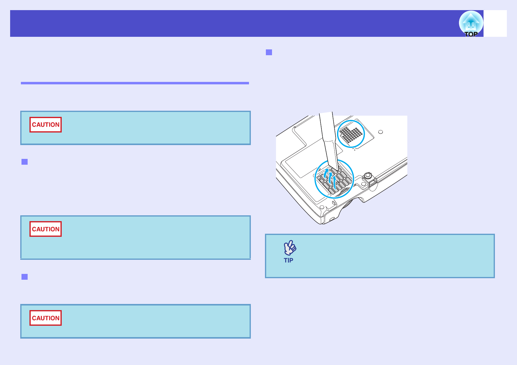
Use a commercially-available air blower, or use a lens cleaning paper to
gently wipe the lens.
If dust collects on the air filter or the air outlet, it can cause the internal
temperature of the projector to rise, and this can lead to problems with
operation and shortening of the optical engine's service life.
It is recommended that you clean these parts at least once every three
months. Clean them more often than this if using the projector in
particularly dusty environments.
Make sure you read the separate Safety Instructions/
World-Wide Warranty Terms before cleaning.
Cleaning the Projector's Surface
Do not use volatile substances such as wax, alcohol or
thinner to clean the projector's surface. These can
cause the projector to warp and make the coating finish
peel off.
Cleaning the Lens
Do not rub the lens with harsh materials or subject the
lens to shocks, as it can easily become damaged.
Cleaning the Air Filters and Air Intake Vent
If the air filters are broken or if the warning message
reappears after they have been cleaned, they should be
replaced. Replace with a new air filter. See "Replacing
the Air Filter". sp.63
58
Maintenance
Replacing Consumables
This section explains how to replace the remote control batteries, the lamp,
and the air filters.
If delays in the responsiveness of the remote control occur or if it does not
operate after it has been used for some time, it probably means that the
batteries are becoming flat. Replace the batteries. Have two spare AAA-
size alkali batteries ready to use when required.
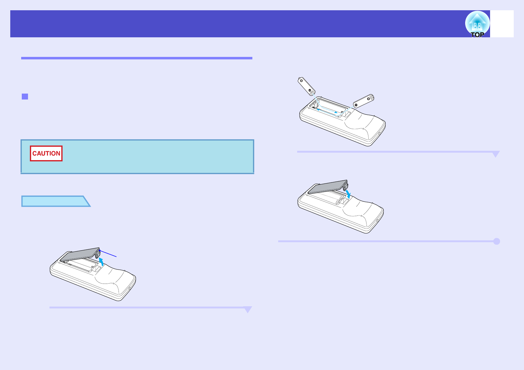
PROCEDURE
A
Remove the battery cover.
While pushing the catch of the battery compartment cover, lift
the cover up.
B
Insert the batteries.
Check the positions of the (+) and (–) marks inside the battery
holder to ensure that the batteries are inserted the correct way.
C
Replace the battery cover.
Press the battery compartment cover until it clicks into place.
Replacing the batteries
Make sure you read the Safety Instructions/World-Wide
Warranty Terms before handling the batteries.
Catch
59
Maintenance
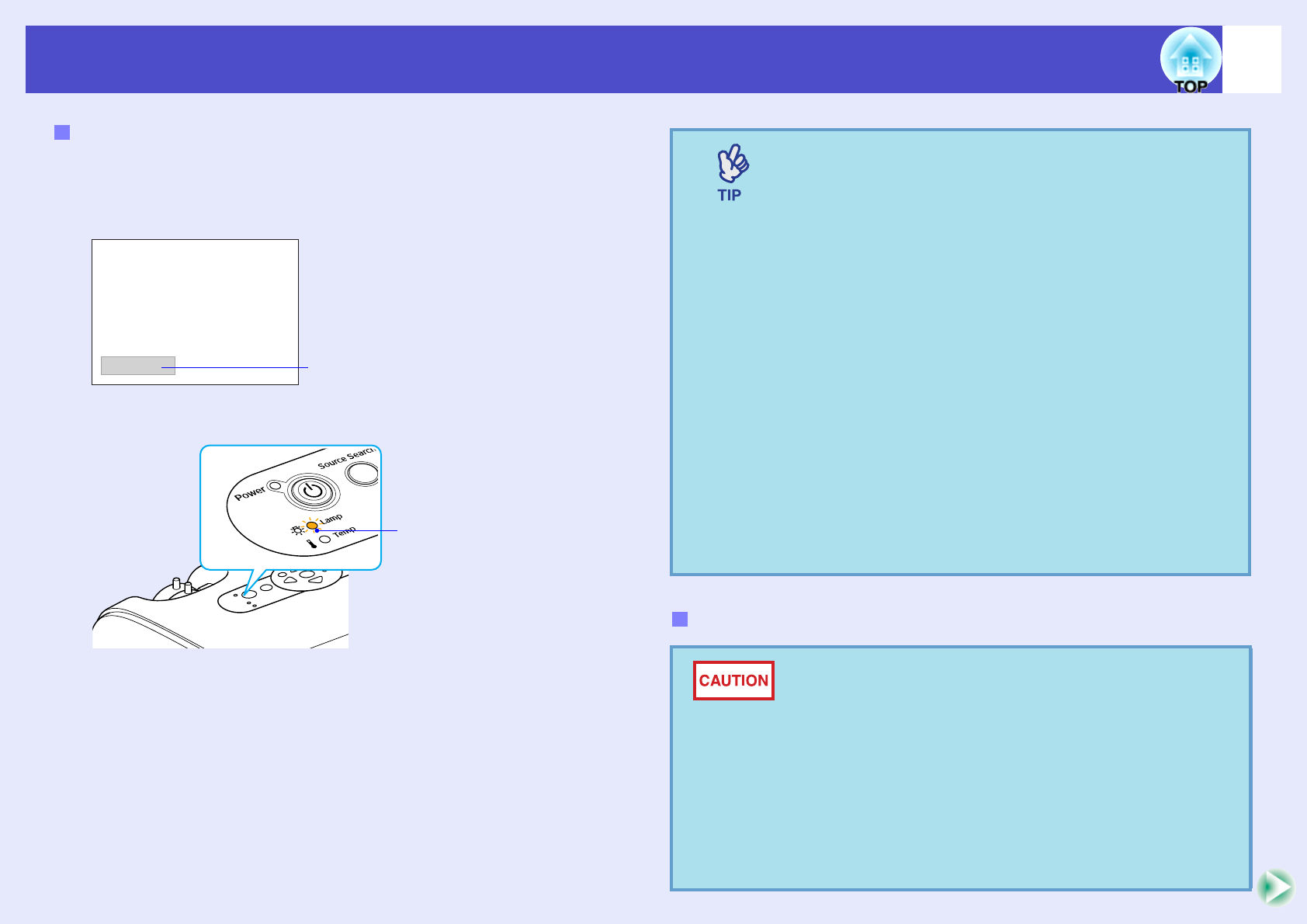
It is time to replace the lamp when:
•The message "Replace the Lamp." appears on the screen when
projection starts
.
•When the Lamp indicator is flashing orange
•The projected image gets darker or starts to deteriorate
Lamp Replacement Period
A message will be displayed.
Flashing orange
•The lamp replacement message is set to appear after the
following periods of time in order to maintain the initial
brightness and quality of the projected images.
"Brightness Control" sp.36
·When used continuously at high brightness: Approx.
1900 hours
·When used continuously at low brightness: Approx.
2900 hours
•If you continue to use the lamp after this period, the
possibility of the lamp breaking becomes greater. When
the lamp replacement message appears, replace the
lamp with a new one as soon as possible, even if it is still
working.
•Depending on the characteristics of the lamp and on
the way it has been used, the lamp may become darker
or stop working before the lamp warning message
appears. You should always have a spare lamp ready in
case it is needed.
•Contact your dealer for a spare lamp.
Replacing the Lamp
•If you are replacing the lamp because it has stopped
working, it is possible that the lamp is broken.
If replacing the lamp of a projector which has been
installed on a ceiling, you should always assume that
the lamp is broken and be extremely careful when
removing the lamp cover.
•Wait until the lamp has cooled down sufficiently before
removing the lamp cover. To give the lamp enough time
to cool down after turning off the power, wait for about
one hour.
60
Maintenance
PROCEDURE
A
After you turn off the projector’s power, and the
confirmation buzzer beeps twice, disconnect the
power cable.
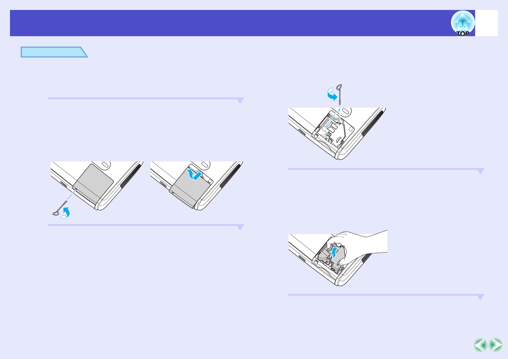
B
Wait until the lamp has cooled down, then remove the
lamp cover from the base of the projector.
Loosen the lamp cover fixing screw with the screwdriver that is
supplied with the spare lamp (or your own cross head
screwdriver).
Then slide the lamp cover straight forward and lift it to remove.
C
Loosen the two lamp fixing screws.
Loosen the two lamp fixing screws with the screwdriver that is
supplied with the spare lamp (or your own cross head
screwdriver).
D
Take out the lamp.
Hold the lamp as shown in the illustration below and lift it up
and out of the projector.
If the lamp is broken replace it with a new lamp, or contact your
local dealer for further advice. If replacing the lamp yourself,
be careful to avoid pieces of broken glass.
61
Maintenance
E
Install the new lamp.
Insert the new lamp so that the lamp fits in place correctly and
once it is fully inserted, tighten the two screws.
F
Install the lamp cover.
Slide the lamp cover and tighten the cover fixing screws.
•Install the lamp securely. If the lamp cover is removed,
the lamp turns off automatically as a safety precaution.
Moreover, the lamp will not turn on if the lamp or the
lamp cover is not installed correctly.
•This product includes a lamp component that contains
mercury (Hg). Please consult your state and local
regurations regarding disposal or recycling. Do not put
in the trash.
62
Maintenance
The projector has a built-in counter which keeps track of the lamp
operating time. When the cumulative operating time reaches a certain
point, it causes the replacement warning message to be displayed.
Therefore, the counter needs to be reset after the lamp has been replaced
with a new one. You can do this using the configuration menu.
PROCEDURE
A
Connect the power cable and turn on the projector.
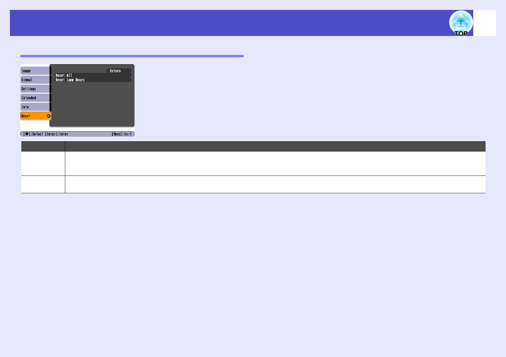
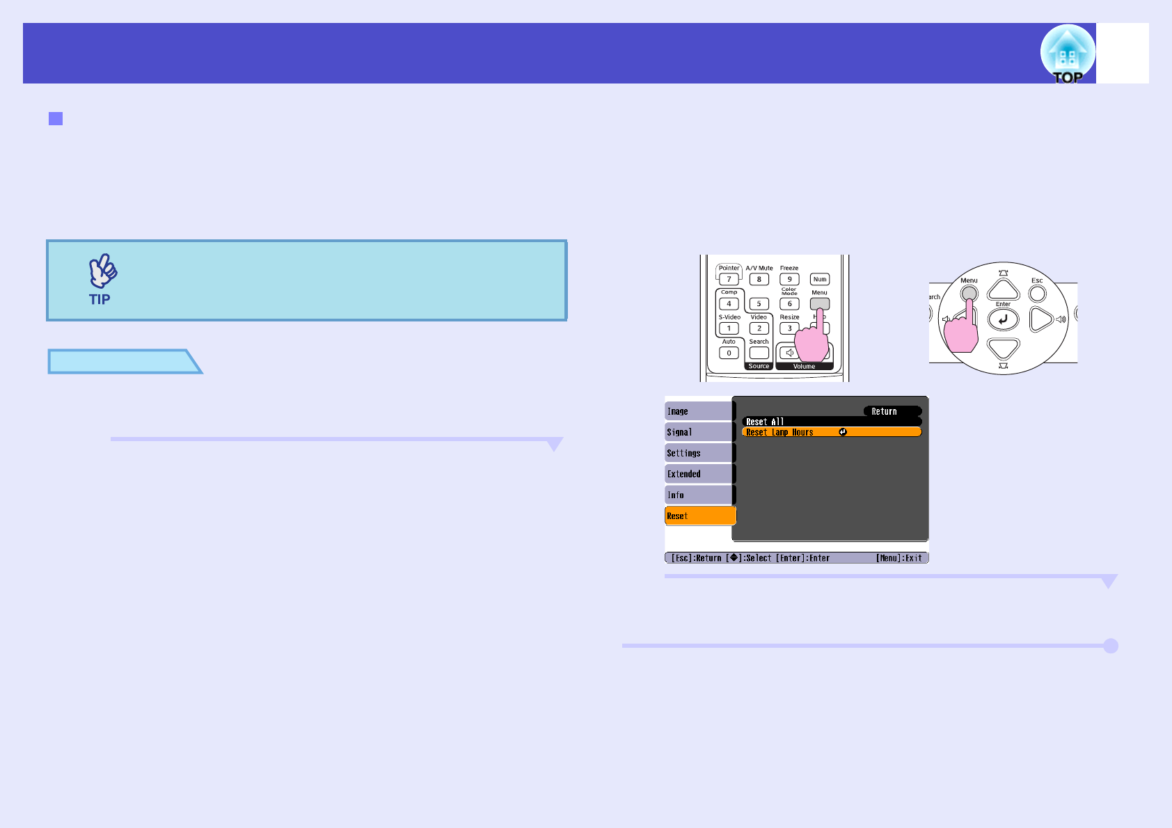
B
Select "Reset" from the configuration menu, and then
select "Reset Lamp Hours".
For details on this operation, refer to
"Using the Configuration
Menu
". sp.32
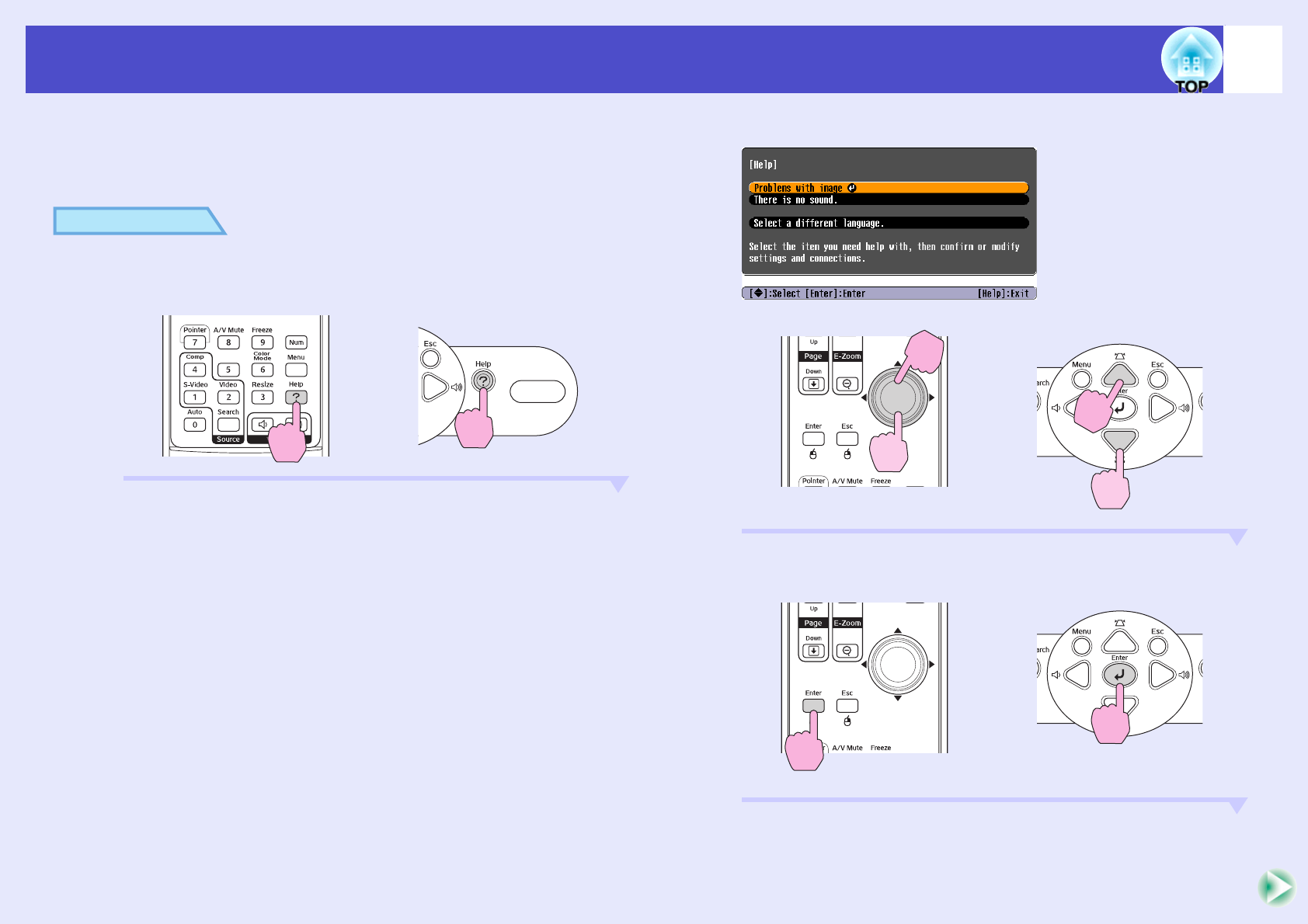
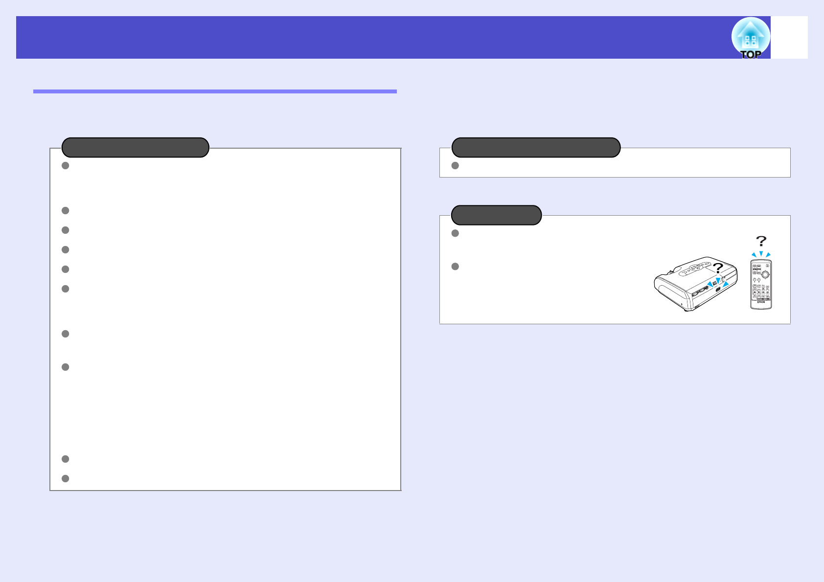
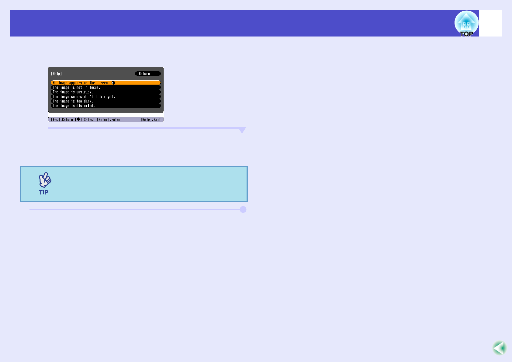
Check the buttons you can use, and the operations they
perform, in the guide at the bottom of the screen.
C
When "Execute?" appears, select "Yes".
The lamp operating time will then be reset.
Resetting the Lamp Operating Time
Do not reset the lamp operating time except after the
lamp has been replaced, otherwise the lamp replacement
period will not be indicated correctly.
Using the remote control
Using the control panel
63
Maintenance
If the air filters are broken or if the warning message reappears after they
have been cleaned, they should be replaced.
The air filter can be replaced even if the projector is installed on a ceiling.
PROCEDURE
A
After you turn off the projector’s power, and the
confirmation buzzer beeps twice, disconnect the
power cable.
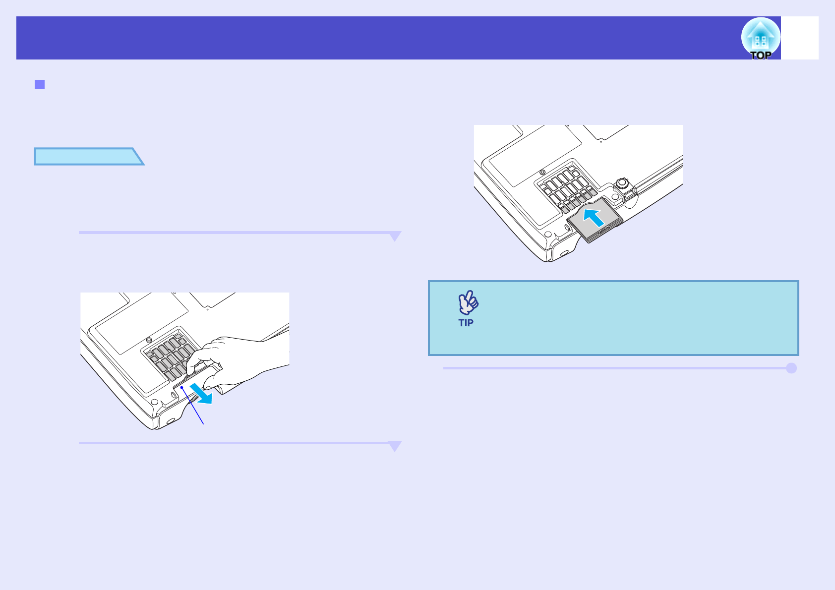
B
Remove the air filter.
Put your finger into the recess of the air filter and slide it
forward to remove it.
C
Install the new air filter.
Slide the air filter covers in from the outside and push them in
until they click into place.
Replacing the Air Filter
Recess
Dispose of used air filters properly in accordance with
your local regulations.
Air filter frame: Polycarbonate, ABS plastic
Filter: Polyurethane foam
64
Saving a User's Logo
You can record the image that is currently being projected as a user's logo.
PROCEDURE
A
Project the image you would like to use as the user’s
logo, and then display the configuration menu.
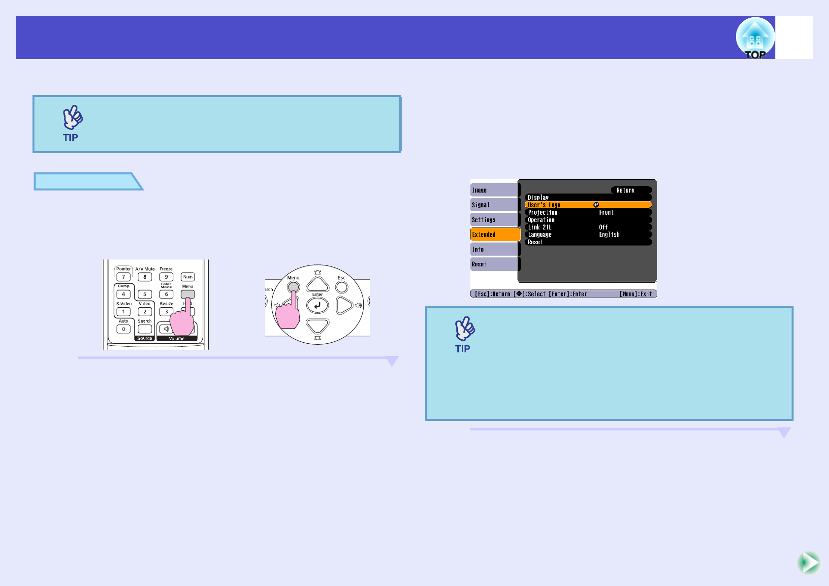
B
Select "Extended" from the configuration menu, and
then select "User’s Logo".
For details on this operation, refer to
"Using the Configuration
Menu
". sp.32
Check which buttons on the remote control or the control panel
you can use, and the operations they perform, in the guide at the
bottom of the screen.
When a user's logo is recorded, the previous user's logo
will be erased.
Using the remote control
Using the control panel
•If the "User’s Logo Protect" function of "Password
Protect" is set to "On", a message is displayed and the
user's logo can not be recorded. To record a user's logo,
set "User’s Logo Protect" to "Off" first. sp.28
•If keystone correction, E-Zoom and so on, have been
carried out, the function currently being performed is
cancelled when the "User’s Logo" menu is selected.
65
Saving a User's Logo
C
When "Choose this image as the User's Logo?"
appears, select "Yes".
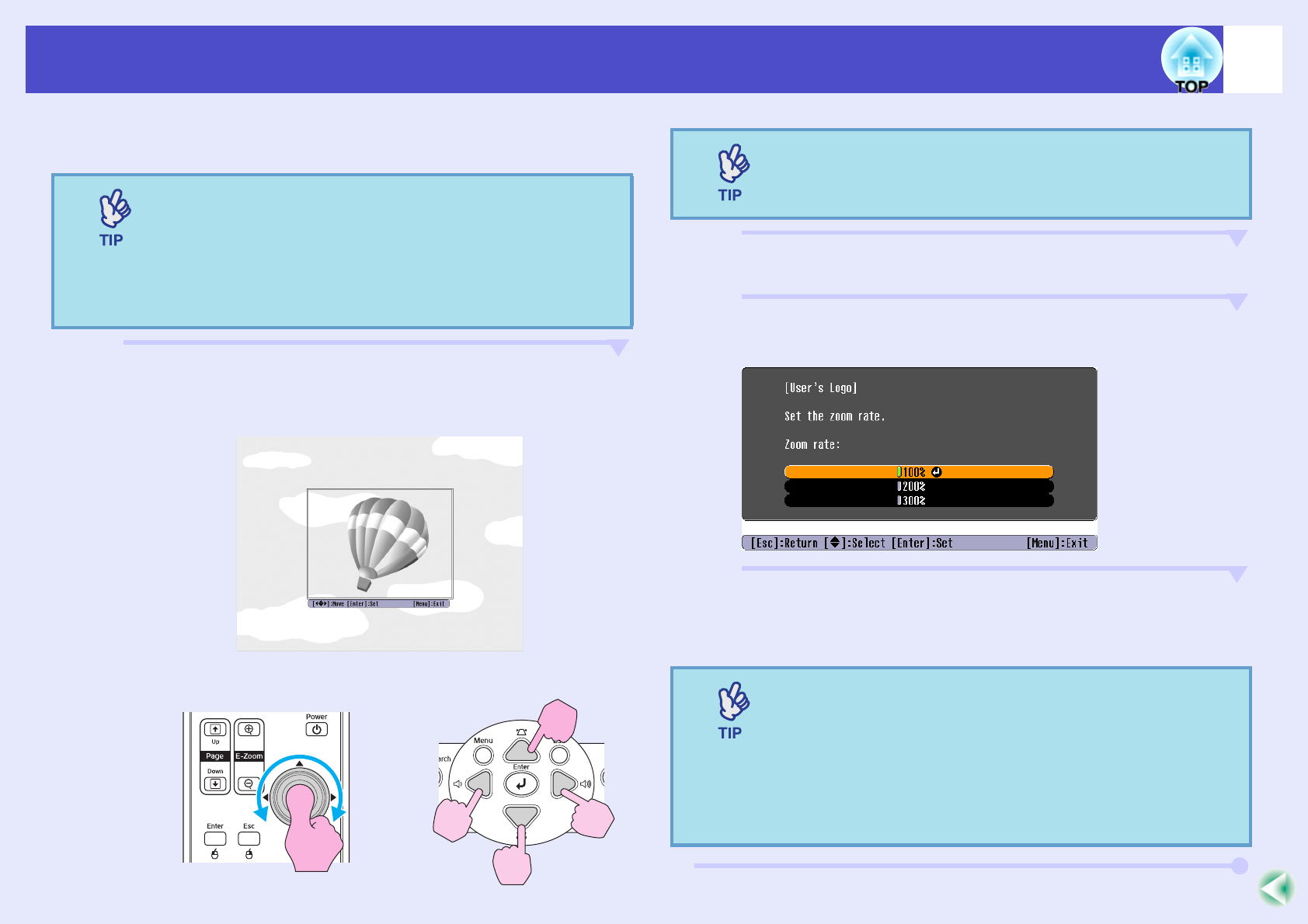
D
The image to be recorded and a selection marquee
box will be displayed. Move the marquee box to select
the part of the image to use.
E
When "Select this image?" appears, select "Yes".
F
Select the zoom rate from the Zoom rate setting
screen.
G
When "Save this image?" is displayed, select "Yes".
The image will then be saved. Once the image has been saved,
the message "Completed." will be displayed.
When you press the [Enter] button on either the remote
control or the projector's control panel, the image signal
will be displayed at their original resolution, so if a
signal with a resolution that is different from the panel
resolution of the projector is projected, or if a video
image is being projected, the display size will change.
Using the remote control
Using the control panel
User's logos can be saved at up to 400 × 300 dots in size.
•Saving the user's logo may take a few moments (about
15 seconds). Do not use the projector or any other
sources which are connected to the projector while the
user's logo is being saved, otherwise it may result in
errors in projector operation.
•Once a user's logo has been saved, the logo setting
cannot be returned to the factory default.
66
Connecting to External Output Equipment
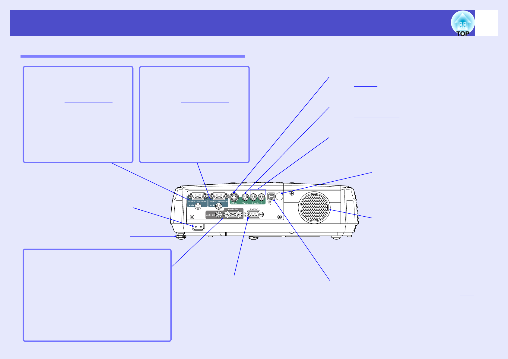
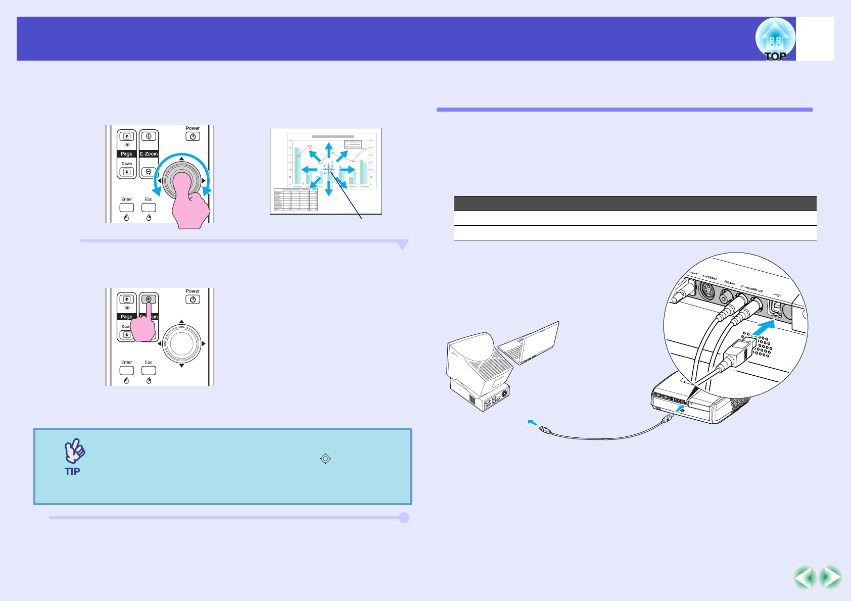
Connecting to an External Monitor
Analogue RGB images and RGB video images from a computer that are
being input to the Computer/Computer1 port can be viewed on an external
computer monitor at the same time they are being projected by the
projector, so that the images can be checked at times such as when giving
presentations.
If the images being projected are from a source that is connected to the
Computer2 port, these images cannot be output to an external monitor.
Connect the external monitor using the cable that is provided with the
monitor.
Connecting to an external speaker (when using the
EMP-82/62)
You can connect speakers with built-in amplifiers to the projector's Audio
Out port in order to enjoy a fuller quality of sound.
Use a commercially-available audio cable with pin jack ⇔ stereo mini jack
(3.5 mm) plugs or similar.
Use an audio cable with plugs that match the ports for the external audio
equipment.
•Component video, S-Video, and composite video images
cannot be output to an external monitor.
•The setting gauge for keystone correction and the
configuration menus and help menus are not output to
the external monitor.
Cable provided with monitorTo Monitor Out port (black)
Monitor port
When a stereo mini-jack audio cable is inserted into the
Audio Out port, the sound will be output to external
speakers. No sound will be output from the projector's
built-in speaker at this time.
Audio cable
(commercially available)
To Audio Out port
To external audio equipment
67
Optional Accessories and Consumables
The following optional accessories are available for purchase if required. This list of optional accessories is current as of March, 2006. Details of accessories are
subject to change without notice. Varies depending on country of purchase.
* A special method of installation is required in order to suspend the
projector from a ceiling. Please contact your dealer if you would like to
use this installation method.
Optional Accessories
Soft carrying case ELPKS16B
Use this case if you need to carry the projector by hand.
60" screen ELPSC07
80" screen ELPSC08
100" screen ELPSC10
Portable roll-type screens. (Aspect ratiog 4:3)
50" portable screen ELPSC06
A compact screen which can be carried easily. (Aspect ratio 4:3)
VGA-HD15 PC cable ELPKC02
(1.8 m (6 ft.) - for mini D-Sub 15-pin/mini D-Sub 15-pin)
This is the same as the computer cable supplied with the projector.
VGA-HD15 PC cable ELPKC09
(3 m (9.8 ft.) - for mini D-Sub 15-pin/mini D-Sub 15-pin)
VGA-HD15 PC cable ELPKC10
(20 m (65.6 ft.) - for mini D-Sub 15-pin/mini D-Sub 15-pin)
Use one of these longer cables if the computer cable supplied with the
projector is too short.
Component video cable ELPKC19
(3 m (9.8 ft.) - for mini D-Sub 15-pin/RCA male × 3)
Use to connect a component videog source.
Ceiling mount * ELPMB18
Use when installing the projector on a ceiling.
Ceiling plate* ELPFC03
Pipe 370 (370 mm (14.57 in.)/silver)* ELPFP04
Pipe 570 (570 mm (22.44 in.)/silver)* ELPFP05
Pipe 770 (770 mm (30.31 in.)/silver)* ELPFP06
Use when installing the projector on a high ceiling or a ceiling with
veneer panels.
Consumables
Spare lamp ELPLP34
Use as a replacement for used lamps.
Filter kit ELPAF08
(2 air filters)
Use as a replacement for used air filters.
68
Glossary
The following is an explanation of some of the terms used in this guide which may be unfamiliar or which are not explained in the text of this guide itself. Further
information can be obtained by referring to other commercially-available publications.
Aspect ratioThe ratio between an image's length and its height. HDTV images have an aspect ratio of 16:9 and appear elongated. The
aspect ratio for standard images is 4:3.
Color Temp.The temperature of an object that is emitting light. If the colour temperature is high, the colours take on a bluish tinge. If the
colour temperature is lower, the colours take on a reddish tinge.
Component videoVideo signals which have the video brightness signals and colour signals separated, in order to provide better image quality.
In high-definition TV (HDTV), it refers to images which consist of three independent signals: Y (luminance signal), and Pb
and Pr (colour difference signals).
Composite videoVideo signals which have the video brightness signals and colour signals mixed together. The type of signals commonly used
by household video equipment (NTSC, PAL and SECAM formats).
The carrier signal Y (luminance signal) and chroma (colour) signal which are contained in the colour bar are overlapped to
form a single signal.
ContrastThe relative brightness of the light and dark areas of an image can be increased or decreased in order to make text and
graphics stand out more clearly, or to make them appear softer. Adjusting this particular property of an image is called
"contrast adjustment".
Dolby DigitalA sound format developed by Dolby Laboratories. Normal stereo is a 2-channel format which uses two speakers. Dolby
Digital is a 6-channel (5.1-channel) system which adds to this a centre speaker two rear speakers and a sub-woofer.
HDTVAn abbreviation for High-Definition Television. It refers to high-definition systems which satisfy the following conditions.
•Vertical resolution of 750p or 1125i or greater (p = progressiveg, i = interlacedg)
•Screen aspect ratiog of 16:9
•Dolby Digitalg audio reception and playback (or output)
InterlacedA method of image scanning whereby the image data is divided into fine horizontal lines which are displayed in sequence
starting from left to right and then from the top to the bottom of the screen. The even-numbered lines and odd-numbered lines
are displayed alternately.
ProgressiveA method of image scanning whereby the image data from a single image is scanned sequentially from top to bottom to create
a single image.
Refresh rateThe light-emitting element of a display maintains the same luminosity and colour for an extremely short time. Because of this,
the image must be scanned many times per second in order to refresh the light-emitting element. The number of refresh
operations per second is called the "refresh rate", and is expressed in hertz (Hz).
SDTVAn abbreviation for Standard Definition Television. It refers to standard television systems which do not satisfy the conditions
for High-Definition Television.
69
Glossary
Security lockA device consisting of a projector case with a hole in it that a commercially-available theft-prevention cable can be passed
through in order to secure the device to a table or pillar. This projector is compatible with the Microsaver Security System
manufactured by Kensington.
Squeeze modeIn this mode, wide-screen images in 16:9 mode are compressed in the horizontal direction so that they are stored on the
recording medium as 4:3 images.
When these images are played back by the projector in squeeze mode, they are restored to their original 16:9 format.
sRGBAn international standard for colour intervals that was formulated so that colours which are reproduced by video equipment
can be handled easily by computer operating systems (OS) and the Internet. If the connected source has a sRGB mode, set
both the projector and the connected signal source to sRGB.
SVGAA type of video signal with a resolution of 800 (horizontal) × 600 (vertical) dots which is used by IBM PC/AT-compatible
computers.
S-VideoA video signal which has the luminance component and colour component separated in order to provide better image quality.
It refers to images which consist of two independent signals: Y (luminance signal), and C (colour signal).
SXGAA type of video signal with a resolution of 1280 (horizontal) × 1024 (vertical) dots which is used by IBM PC/AT-compatible
computers.
Sync (synchronisation)The signals output from computers and RGB video equipment have a specific frequency. If the projector frequency does not
match this frequency, the resulting images will not be of a good quality. The process of matching the phases of these signals
(the relative position of the crests and troughs in the signal) is called "synchronisation". If the signals are not synchronized,
problems such as flickering, blurriness and horizontal interference can occur.
TrackingThe signals output from computers and RGB video equipment have a specific frequency. If the projector frequency does not
match this frequency, the resulting images will not be of a good quality. The process of matching the frequency of these
signals (the number of crests in the signal) is called "tracking". If tracking is not carried out correctly, wide vertical stripes will
appear in the projected images.
USBAn abbreviation for Universal Serial Bus. USB is an interface for connecting personal computers to peripheral devices which
only support relatively low data transmission speeds.
VGAA type of video signal with a resolution of 640 (horizontal) × 480 (vertical) dots which is used by IBM PC/AT-compatible
computers.
XGAA type of video signal with a resolution of 1024 (horizontal) × 768 (vertical) dots which is used by IBM PC/AT-compatible
computers.
70
List of ESC/VP21 Commands
Command List
When a power on command is sent to the projector, the power will turn on
and the projector will change to warm-up mode. When the power has
turned on, a colon ":" (3Ah) will be returned.
When the projector executes a command, it returns a ":" and waits for the
next command to be sent.
If command processing terminates with an error, the projector outputs an
error message and then returns the ":" code.
*When issuing any of the above commands, tack a Carriage Return (CR)
code (0Dh) on to the end.
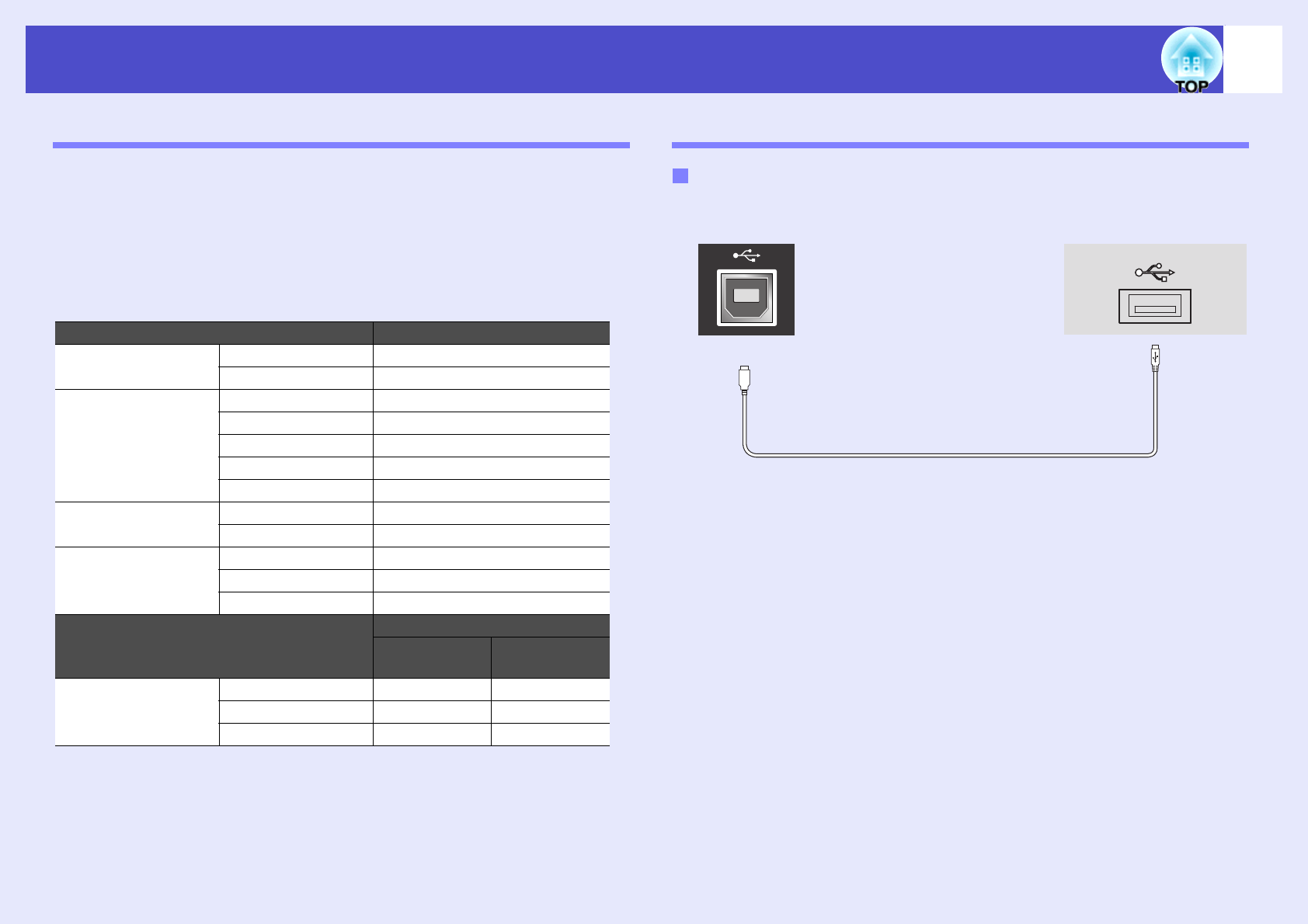
Cable Layouts
Connector shape: USB (type B)
ItemCommand
Power ON/OFF
ONPWR ON
OFFPWR OFF
Signal selection
Computer (Auto)SOURCE 1F
ComputerSOURCE 11
Component VideoSOURCE 14
VideoSOURCE 41
S-VideoSOURCE 42
A/V Mute ON/OFF
ONMUTE ON
OFFMUTE OFF
A/V Mute Selection
BlackMSEL 00
BlueMSEL 01
User’s LogoMSEL 02
Item
Command
Computer1
port
Computer2
port
Signal selection
Computer (Auto)SOURCE 1FSOURCE 2F
ComputerSOURCE 11SOURCE 21
Component VideoSOURCE 14SOURCE 24
USB connection
<At the projector><At the computer>
(type B)
71
List of ESC/VP21 Commands
USB Connection Setup
In order to control the projector using ESC/VP21 commands via a USB
connection, the following preparations must be carried out.
PROCEDURE
A
Download the USB driver (USB-COM Driver) from the
EPSON website to your computer.
The URL is as follows.
http://esupport.epson-europe.com/downloads/en/
B
Install the downloaded USB driver onto your
computer.
Read the instructions displayed on the download screen.
C
<Using EMP-X3>
Set "Link21L" to "On" in the "Extended" menu.
<Using EMP-82/62>
Select "USB" for "COM port" in the "Extended" menu.
D
Turn the projector's power off.
E
Turn off this projector after the confirmation buzzer
beeps twice.
Once the projector's power has turned back on, communication
via a USB Connection will then be possible.
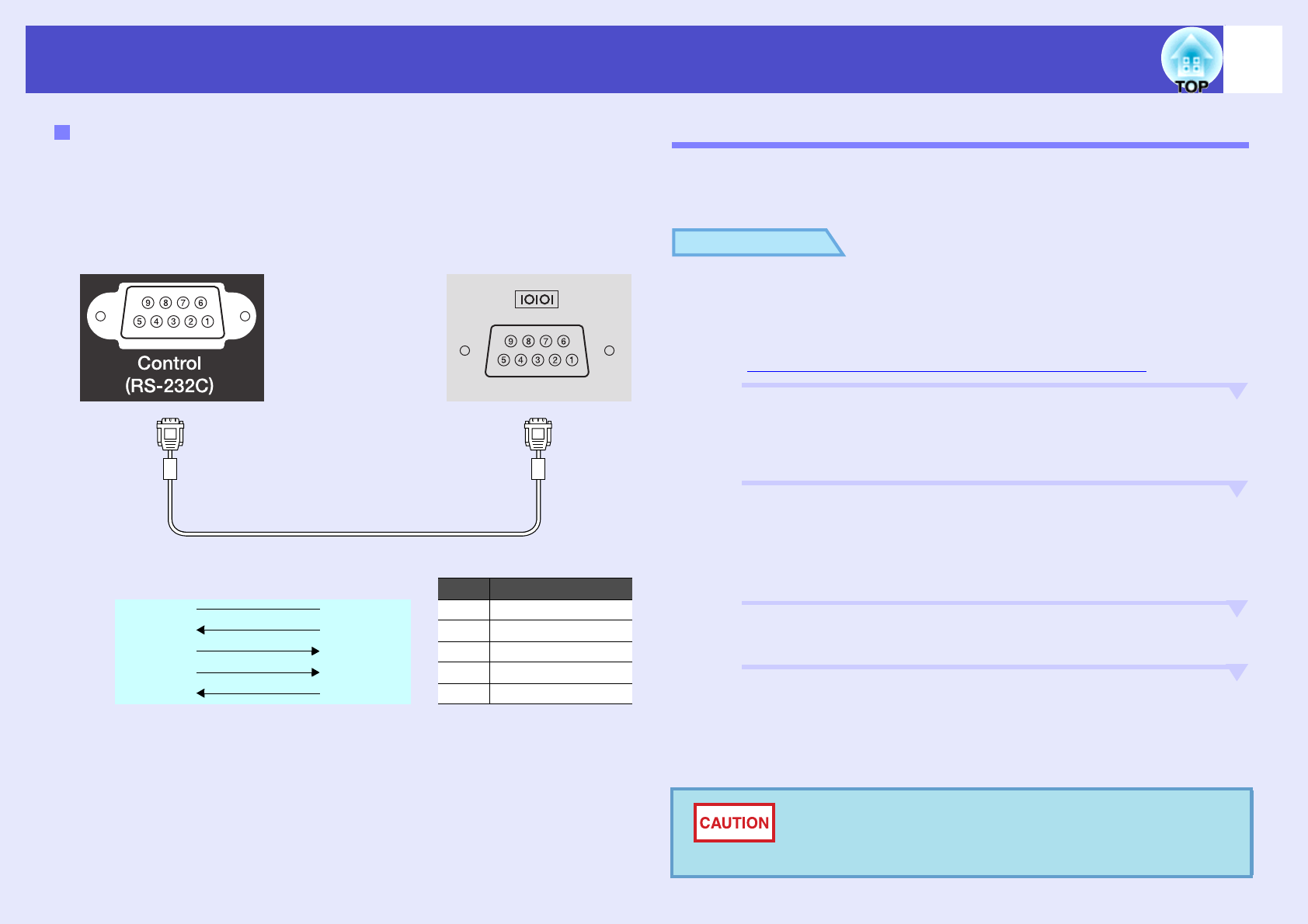
Serial connection (EMP-82/62 only)
•Connector shape: D-Sub 9 pin (male)
•Projector input connector: Control (RS-232C)
<At computer>
<At projector>(PC serial cable)<At computer>
SignalFunction
GND55GND
GNDSignal wire ground
RD23TD
TDTransmit data
TD32RD
RDReceive data
DTR46DSR
DSRData set ready
DSR64DTR
DTRData terminal ready
<At projector>
If you disconnect the power cable before the
confirmation buzzer beeps twice, the communication
port is not changed.
72
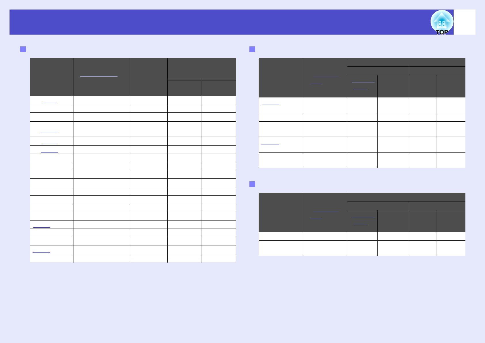
List of Supported Monitor Displays
*Connection is not possible if the equipment does not have a VGA output
port.
The projection of some signals not listed in the table may still be possible.
However, not all functions may be supported.
Computer/RGB Video
Signal
Refresh rateg
(Hz)
Resolution
(dots)
Resolutions for
resize display
(dots)
EMP-
X3/82
EMP-62
VGAg60640×4801024×768800×600
VGAEGA640×3501024×560800×438
VESA60/72/75/85,iMac*640×4801024×768800×600
SVGAg
56/60/72/75/
85,iMac*
800×6001024×768800×600
XGAg60/70/75/85,iMac*1024×7681024×768800×600
SXGAg70/75/851152×8641024×768800×600
SXGA60/75/851280×9601024×768800×600
SXGA60/75/851280×1024960×768750×600
UXGA601600×12001024×768-
MAC13"640×4801024×768800×600
MAC16"832×6241024×768800×600
MAC19"1024×7681024×768800×600
MAC19"601024×7681024×768800×600
MAC21"1152×8701016×768794×600
SDTVg(625i)50720×5761024×768800×600
SDTV(525i)60720×4801024×768800×600
SDTV(525p)60640×4801024×768800×600
HDTV
g
(750p)
601280×7201024×576800×450
HDTV(1125i)601920×10801024×576800×450
Component Video
Signal
Refresh
rateg (Hz)
Resolutions (dots)
EMP-X3/82EMP-62
Aspect
ratiog
4:3
Aspect
ratio
16:9
Aspect
ratio
4:3
Aspect
ratio
16:9
SDTV
g(525i)
(D1)
601024×7681024×576800×600800×450
SDTV (625i)501024×7681024×576800×600800×450
SDTV (525p)
(D2)
601024×7681024×576800×600800×450
HDTV
g(750p)
16:9 (D4)
601024×7681024×576800×600800×450
HDTV (1125i)
16:9 (D3)
601024×7681024×576800×600800×450
Composite Video/S-Video
Signal
Refresh
rateg (Hz)
Resolutions (dots)
EMP-X3/82EMP-62
Aspect
ratiog
4:3
Aspect
ratio
16:9
Aspect
ratio
4:3
Aspect
ratio
16:9
TV (NTSC)601024×7681024×576800×600800×450
TV (PAL,
SECAM)
501024×7681024×576800×600800×450
73
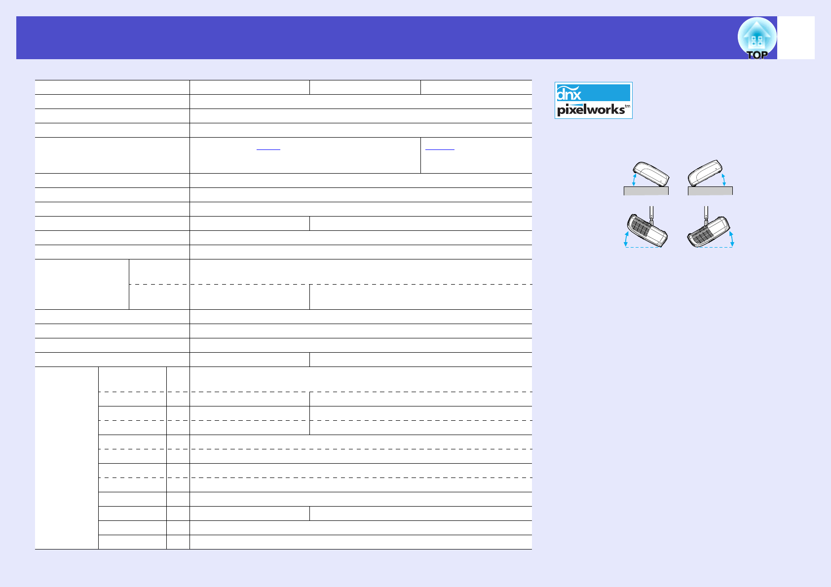
Specifications
Product nameEMP-X3EMP-82EMP-62
Dimensions327 (W) × 86 (H) × 246 (D) mm (not including feet and speaker)
Panel size0.6 inches
Display methodPolysilicon TFT active matrix
ResolutionXGAg 786,432 pixels
(1024 (W) × 768 (H) dots) × 3
SVGAg 480,000 pixels
(800 (W) × 600 (H)
dots) × 3
Focus adjustmentManual
Zoom adjustmentManual (approx. 1:1.2)
Lamp (light source)UHE lamp, 170 W, Model No.: ELPLP34
Max. audio output1W monaural5W monaural
Speaker1
Power supply100 to 240VAC 50/60Hz 2.9 to 1.2A
Power
Consumption
Operating250W (100 to 120V area)
240W (220 to 240V area)
Standby5W (100 to 120V area)
6W (220 to 240V area)
4W (100 to 120V area)
5W (220 to 240V area)
Operating altitude0 to 2286 m (0 to 7500 ft)
Operating temperature+5 to +35ºC (No condensation)
Storage temperature-10 to +60ºC (No condensation)
WeightApprox. 2.6 kgApprox. 2.7 kg
ConnectorsComputer/
Computer 1
1Mini D-Sub 15-pin
(female) Blue
Audio Input1RCA pin jackStereo mini jack
Computer 21-Mini D-Sub 15-pin (female) Blue
Audio Input1-Stereo mini jack
S-Video1Mini DIN 4-pin
Audio Input1RCA pin jack
Video1RCA pin jack
Audio Input1RCA pin jack
USB*1USB connector (B series)
RS-232C1-D-Sub 9-pin (male)
Monitor Out1Mini D-Sub 15-pin (female) Black
Audio Out1Stereo mini jack
Angle of tilt
If you use it when it is tilted more than 30°, it
could be damaged and cause an accident.
*The USB interface complies with the USB 1.1
standard.
The USB connector is not guaranteed to operate
correctly with all USB-compatible devices.
Pixelworks DNX
TM
ICs are used
in this Projector.
0 to 30°0 to 30°
0 to 30°0 to 30°
74
Specifications
Safety
USA
UL60950 3rd Edition
Canada
CSA C22.2 No.60950
European Community
The Low Voltage Directive
(73/23/EEC)
IEC60950 3rd Edition
EMC
USA
FCC Part 15B Class B (DoC)
Canada
ICES-003 Class B
European Community
The EMC Directive
(89/336/EEC)
EN55022 Class B
EN55024
IEC/EN61000-3-2
IEC/EN61000-3-3
Australia/New Zealand
AS/NZS CISPR 22:2002 Class B
75
We:EPSON AMERICA, INC.
Located at :3840 Kilroy Airport Way
MS: 3-13
Long Beach, CA 90806
Tel:562-290-5254
Declare under sole responsibility that the product identified herein,
complies with 47CFR Part 2 and 15 of the FCC rules as a Class B digital
device. Each product marketed, is identical to the representative unit
tested and found to be compliant with the standards. Records maintained
continue to reflect the equipment being produced can be expected to be
within the variation accepted, due to quantity production and testing on a
statistical basis as required by 47CFR 2.909. Operation is subject to the
following two conditions : (1) this device may not cause harmful
interference, and (2) this device must accept any interference received,
including interference that may cause undesired operation.
Trade Name:EPSON
Type of Product:Projector
Model:EMP-82/62/X3
FCC Compliance Statement
For United States Users
This equipment has been tested and found to comply with the limits for a
Class B digital device, pursuant to Part 15 of the FCC Rules. These limits
are designed to provide reasonable protection against harmful
interference in a residential installation. This equipment generates, uses,
and can radiate radio frequency energy and, if not installed and used in
accordance with the instructions, may cause harmful interference to radio
or television reception. However, there is no guarantee that interference
will not occur in a particular installation. If this equipment does cause
interference to radio and television reception, which can be determined by
turning the equipment off and on, the user is encouraged to try to correct
the interference by one or more of the following measures.
•Reorient or relocate the receiving antenna.
•Increase the separation between the equipment and receiver.
•Connect the equipment into an outlet on a circuit different from that to which
the receiver is connected.
•Consult the dealer or an experienced radio/TV technician for help.
WARNING
The connection of a non-shielded equipment interface cable to this
equipment will invalidate the FCC Certification or Declaration of this device
and may cause interference levels which exceed the limits established by
the FCC for this equipment. It is the responsibility of the user to obtain and
use a shielded equipment interface cable with this device. If this
equipment has more than one interface connector, do not leave cables
connected to unused interfaces. Changes or modifications not expressly
approved by the manufacturer could void the user’s authority to operate
the equipment.
DECLARATION of CONFORMITY
According to 47CFR, Part 2 and 15
Class B Personal Computers and Peripherals; and/or
CPU Boards and Power Supplies used with Class B
Personal Computers
76
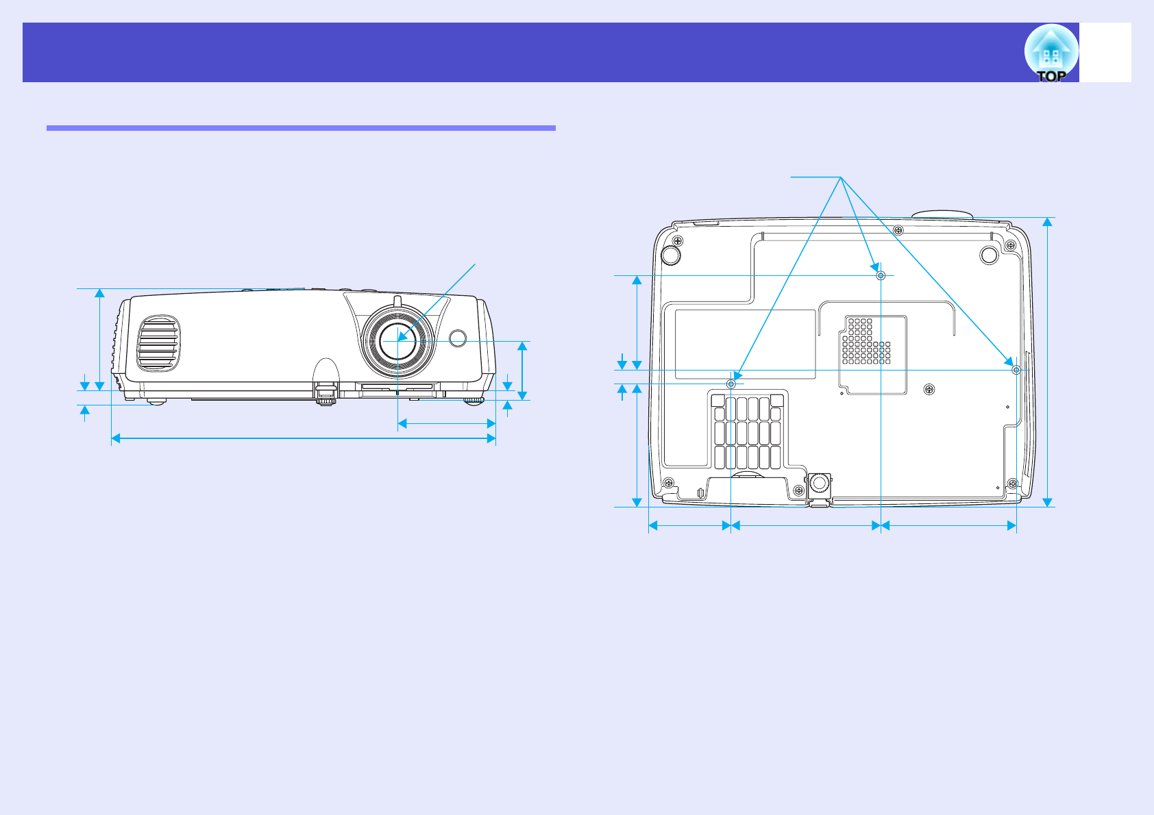
Appearance
EMP-X3
Units: mm
3-M4×9
115127
80
12
104.7
327
83.7
50.1*
7.7
86
Centre of lens
69.7
12
*Distance from center of lens to suspension bracket fixing point
246
77
Appearance
EMP-82/62
Units: mm
3-M4×9
115127
80
12
104.7
327
83.7
50.1*
7.7
86
Centre of lens
69.7
12
*Distance from center of lens to suspension bracket fixing point
246
78
Index
A
Air exhaust vent.............................6
Air filter....................................... 10
Air intake vent.............................10
Angle of tilt.................................. 73
Libble takes abuse of its services very seriously. We're committed to dealing with such abuse according to the laws in your country of residence. When you submit a report, we'll investigate it and take the appropriate action. We'll get back to you only if we require additional details or have more information to share.
Product:
Forumrules
To achieve meaningful questions, we apply the following rules:
First, read the manual;
Check if your question has been asked previously;
Try to ask your question as clearly as possible;
Did you already try to solve the problem? Please mention this;
Is your problem solved by a visitor then let him/her know in this forum;
To give a response to a question or answer, do not use this form but click on the button 'reply to this question';
Your question will be posted here and emailed to our subscribers. Therefore, avoid filling in personal details.
Register
Register getting emails for Epson EMP-62 at:
new questions and answers
new manuals
You will receive an email to register for one or both of the options.
Get your user manual by e-mail
Enter your email address to receive the manual of Epson EMP-62 in the language / languages: English as an attachment in your email.
The manual is 4,59 mb in size.
You will receive the manual in your email within minutes. If you have not received an email, then probably have entered the wrong email address or your mailbox is too full. In addition, it may be that your ISP may have a maximum size for emails to receive.
If you have not received an email with the manual within fifteen minutes, it may be that you have a entered a wrong email address or that your ISP has set a maximum size to receive email that is smaller than the size of the manual.
The email address you have provided is not correct.
Please check the email address and correct it.
Your question is posted on this page
Would you like to receive an email when new answers and questions are posted? Please enter your email address.