499652
66
Zoom out
Zoom in
Previous page
1/73
Next page
Evolution Line
SOLEIL - TANIA- POLARIS
I SOLEIL-TANIA-POLARIS, Installazione, uso e manutenzione p. 2
UK SOLEIL-TANIA-POLARIS, Installation, use and maintenance p. 26
F SOLEIL-TANIA-POLARIS, Installation, usage et maintenance p. 50
ES SOLEIL-TANIA-POLARIS, Instalación, uso y mantenimiento p. 74
DE SOLEIL-TANIA-POLARIS, Installations-, Betriebs- und Wartungsanleitung p. 98
NL SOLEIL-TANIA-POLARIS, Installatie, gebruik en onderhoud p. 122
sk tecnica soleil-polaris-tania multilingua_fra ristampa febbraio 2010.qxp 24/02/2010 9.08 Pagina 2
Gentile Sig.ra/Egregio Signore
La ringraziamo per avere scelto la nostra stufa.
Prima di utilizzare la stufa, Le chiediamo di leggere attentamente questa scheda, al fine di poterne sfruttare al meglio e in tota-
le sicurezza tutte le caratteristiche.
Per ulteriori chiarimenti o necessità contatti il suo Rivenditore di zona o visiti il nostro sito internet alla voce CENTRI ASSI-
STENZA TECNICA
Le ricordiamo che, per la funzionalità e taratura della stufa, la 1° accensione DEVE essere effettuata da CAT (centro di
assistenza tecnica abilitato) che verifichi l'installazione, tari la stufa, e compili la garanzia.
Dal rivenditore, al numero verde o sul sito www
.edilkamin.com può trovare il nominativo del Centro Assistenza più vicino.
NOTA
• Dopo aver disimballato la stufa, assicurarsi dell'integrità e della completezza del contenuto. In caso risultasse
qualcosa fuori posto, rivolgersi al rivenditore da cui è stata acquistata.
• 1° Messa in servizio/Collaudo
Deve essere assolutamente eseguita dal - Centro Assistenza Tecnica - autorizzato (CAT)
La messa in servizio, così come descritto dalla norma UNI 10683 rev. 2005, (capitolo "3.21") consiste in una serie di ope-
razioni di controllo eseguite a stufa installata e finalizzate ad accettare il corretto funzionamento del sistema e la rispon-
denza dello stesso alla normativa.
• Installazioni scorrette, manutenzioni non correttamente effettuate, uso improprio del prodotto sollevano l'azienda produt-
trice da ogni eventuale danno derivante dall'uso.
In caso di fallita accensione, NON ripetere l’accensione prima di avere svuotato il crogiolo
DICHIARAZIONE DI CONFORMITA
La scrivente EDILKAMIN S.p.a. con sede legale in C.so di Porta Romana 116/a –20122 Milano –Cod. Fiscale P.IVA 00192220192
Dichiara sotto la propria responsabilità che:
Le stufe a pellet di legno sotto riportate sono conformi alla Direttiva 89/106/CEE (Prodotti da Costruzione)
STUFE A PELLET, a marchio commerciale EDILKAMIN, denominate SOLEIL-TANIA-POLARIS
MODELLO: SOLEIL-TANIA-POLARIS N° di SERIE: Rif. Targhetta dati
ANNO DI FABBRICAZIONE: Rif. Targhetta dati
La conformità ai requisiti della Direttiva 89/106/CEE è inoltre determinata dalla conformità alla norma europea:
EN 14785:2004 come da test report 400305 emesso da:
KIWA GASTEC ITALIA S.P.A. Organismo notificato NB 0694
e da documentazione consegnata a KIWA GASTEC ITALIA S.p.a.
Altresì dichiara che:
le stufe a pellet di legno SOLEIL-TANIA-POLARIS rispettano i requisiti delle direttive europee:
2006/95/CEE – Direttiva Bassa Tensione
89/336/CEE – Direttiva Compatibilità Elettromagnetica
EDILKAMIN S.p.a. declina ogni responsabilità di malfunzionamento dell’apparecchiatura in caso di sostituzione,
montaggio e/o modifiche effettuate non da personale EDILKAMIN senza autorizzazione della scrivente.
ITALIANO
2
sk tecnica soleil-polaris-tania multilingua_fra ristampa febbraio 2010.qxp 24/02/2010 9.08 Pagina 3
PRINCIPIO DI FUNZIONAMENTO
Le stufe SOLEIL - TANIA- POLARIS (versione base o cana-
lizzabile) utilizzano come combustibile il pellet di legno, la
cui combustione è gestita elettronicamente. Le stufe sono rea-
lizzate con una struttura interna completamente in ghisa.
Di seguito ne è illustrato il funzionamento (Le lettere fanno
riferimento alla figura 1). Il combustibile (pellet) viene prele-
vato dal serbatoio di stoccaggio (A) e, tramite una coclea (B)
attivata da motoriduttore (C), viene trasportato nel crogiolo di
combustione (D). L'accensione del pellet avviene tramite aria
calda prodotta da una resistenza elettrica (E) e aspirata nel cro-
giolo tramite un ventilatore centrifugo (F). I fumi prodotti
dalla combustione, vengono estratti dal focolare tramite lo
stesso ventilatore centrifugo (F), ed espulsi dal bocchettone
(G) ubicato nella zona bassa del retro delle stufe. L'aria per il
riscaldamento segue due distinti percorsi nelle due parti destra
e sinistra della stufa (fig. 2 pag. 4). Nella metà destra della
stufa l'aria entra nella parte superiore per transitare nell'inter-
capedine sul retro del focolare, dove si riscalda per poi uscire
in ambiente dalla griglia frontale superiore (H), rif. circuito A
(fig. 2 pag. 4). Nella metà sinistra della stufa l'aria entra nella
parte inferiore per transitare (prima in senso ascendente e poi
discendente) nell'intercapedine sul retro del focolare, dove si
riscalda per poi uscire in ambiente dalla griglia frontale infe-
riore (I) o (versione canalizzata) dall'apposito bocchettone
posteriore di canalizzazione. Dal bocchettone con apposite
tubazioni, l'aria può essere convogliata in un locale adiacente
(L), rif. circuito A (fig. 2 pag. 4). Nella metà di destra della
stufa l'aria entra nella parte superiore per transitare (prima in
senso discendente e poi in senso ascendente) nell'intercapedi-
ne sul retro del focolare, dove si riscalda per poi uscire in
ambiente dalla griglia frontale superiore. La quantità di com-
bustibile e l'estrazione fumi/alimentazione aria comburente,
sono regolate tramite scheda elettronica dotata di software con
sistema Fire Control al fine di ottenere una combustione ad
alto rendimento e basse emissioni. Sulla parte frontale superio-
re è installato il pannello sinottico (M) che consente la gestio-
ne e la visualizzazione di tutte le fasi di funzionamento. Le
principali fasi possono essere gestite anche attraverso il tele-
comando. La stufa è dotata sul retro di una presa seriale per
collegamento (con cavetto optional cod. 621240) a dispositivi
di accensione remota (quali combinatori telefonici, cronoter-
mostati ect.). Le due versioni disponibili sono:
• base,
• canalizzabile.
INFORMAZIONI PER LA
SICUREZZA
Le stufe SOLEIL - TANIA - POLARIS sono progettate
per scaldare, attraverso una combustione automatica di
pellet nel focolare, il locale nel quale si trovano per irrag-
giamento e per movimento di aria che esce dalle griglie
frontali, con la possibilità di riscaldare il locale attiguo tra-
mite il movimento dell'aria canalizzabile dalla bocchetta
sul retro.
Gli unici rischi derivabili dall'impiego delle stufe sono
legati a un non rispetto dell'installazione o a un diretto
contatto con parti elettriche in tensione (interne) o a un
contatto con fuoco e parti calde (vetro, tubi, uscita aria
calda) o all'introduzione di sostanze estranee.
Usare come combustibile solo pellet di legno.
Nel caso di mancato funzionamento di componenti, le
stufe sono dotate di dispositivi di sicurezza che ne garan-
tiscono lo spegnimento, da lasciar avvenire senza intervenire.
Per un regolare funzionamento la stufa deve essere instal-
lata rispettando quanto su questa scheda e durante il fun-
zionamento non deve essere aperta la porta:
la combustione è infatti gestita automaticamente e non
necessita di alcun intervento.
In nessun caso devono essere introdotte nel focolare o nel
serbatoio sostanze estranee.
Per la pulizia del canale da fumo (tratto di canna che col-
lega il bocchettone di uscita fumi della stufa con la canna
fumaria) non devono essere utilizzati prodotti infiammabili.
Le parti del focolare e del serbatoio devono essere solo
aspirate con aspirapolvere.
Il vetro può essere pulito a FREDDO con apposito prodot-
to (es. GlassKamin) e un panno.
Non pulire a caldo.
Assicurarsi che le stufe vengano posate e accese da (cen-
tro assistenza tecnica) CAT abilitato secondo le indicazio-
ni della presente scheda.
Durante il funzionamento della stufa, i tubi di scarico e la
porta raggiungono alte temperature.
Non depositare oggetti non resistenti al calore nelle imme-
diate vicinanze della stufa.
Non usare MAI combustibili liquidi per accendere la stufa
o ravvivare la brace.
Non occludere le aperture di aerazione nel locale di instal-
lazione, né gli ingressi di aria della stufa stessa.
Non bagnare la stufa, non avvicinarsi alle parti elettriche
con le mani bagnate.
Non inserire riduzioni sui tubi di scarico fumi.
La stufa deve essere installata in locali adeguati alla pre-
venzione antincendio e serviti da tutti i servizi (alimenta-
zione e scarichi) che l'apparecchio richiede per un corretto
e sicuro funzionamento.
ITALIANO
3
Fig. 1
sk tecnica soleil-polaris-tania multilingua_fra ristampa febbraio 2010.qxp 24/02/2010 9.08 Pagina 4
ITALIANO
4
CIRCOLAZIONE ARIA CALDA
A
B
A
B
Fig. 2
sk tecnica soleil-polaris-tania multilingua_fra ristampa febbraio 2010.qxp 24/02/2010 9.08 Pagina 5
ITALIANO
5
CANALIZZAZIONE
(SOLO per VERSIONE CANALIZZABILE)
La stufa è dotata di bocchetta sul retro (vedere posiziona-
mento pag. 6 INGOMBRI) per la canalizzazione dell'aria
nel locale attiguo attraverso apposito Kit 8 optional (cod.
297360) formato da:
• fascetta stringitubo
• tubo flessibile Ø 10 lunghezza 1,5 m
• bocchetta
Oppure il Kit 9 optional (cod. 299440) per la canalizza-
zione in due locali adiacenti, composto da:
• n° 2 Tubo flessibile Ø 10 da 1,5 m
• n° 4 Fascette stringitubo Ø 14 cm.
• n° 2 Kit Bocchetta aria canalizzata Ø 10 cm
• n° 1 Raccordo a V Ø 10 cm
È importante ricordare l'importanza di opportuna coiben-
tazione del tubo in cui passa l'aria calda per evitare
dispersioni.
Sono da evitare il più possibile curve del tubo stesso.
La distribuzione dell'aria canalizzata è regolabile nel
tempo e nella intensità da pannello sinottico (vedere
pagina 13). Ciò significa che l'aria può essere indirizzata
o nella parte bassa frontale o nella parte posteriore (rife-
rimento figura 2 pagina 4)
NOTA
Nel caso si desideri trasformare la versione base in ver-
sione canalizzabile è necessario contattare il rivenditore e
il Centro Assistenza Tecnica (CAT) per poter acquistare
l'apposito kit (cod. 297350) che dovrà essere installato e
collegato all'interno della stufa.
Nella versione base NON canalizzata, l'aria calda esce
dalla griglia frontale superiore semiparte DX e dalla
griglia frontale inferiore semiparte SX.
CARICAMENTO DEL PELLET NEL
SERBATOIO
Il coperchio del serbatoio si apre e si chiude attraverso il
pratico sistema a clik-clak esercitando una leggera pressione
sul coperchio in ghisa. (fig. 3)
ATTENZIONE : utilizzare apposito guanto in dotazione
se si carica la stufa mentre è in funzione e quindi calda.
Fig. 3
Fig. 4
NOTA sul combustibile.
Queste stufe sono progettate e programmate per bruciare pellet di legno di diametro di 6 mm circa. Il pellet è un combustibile
che si presenta in forma di piccoli cilindri del diametro di 6 mm circa, ottenuti pressando segatura, ad alti valori, senza uso di
collanti o altri materiali estranei. E' commercializzato in sacchetti da 15 Kg.
Per NON compromettere il funzionamento delle stufe è indispensabile NON bruciarvi altro. L'impiego di altri materiali (legna
compresa), rilevabile da analisi di laboratorio, implica la decadenza della garanzia.
Edilkamin ha progettato, testato e programmato i propri prodotti perché garantiscano le migliori prestazioni con pellet delle
seguenti caratteristiche:
diametro : 6 millimetri
lunghezza massima : 40 mm
umidità massima : 8 %
resa calorica : 4300 kcal/kg almeno
L'uso di pellet con diverse caratteristiche implica la necessità di una nuova taratura delle stufe, analoga a quella che fa il CAT
(centro assistenza tecnica) in 1° accensione.
L'uso di pellet non idonei può provocare: diminuzione del rendimento; anomalie di funzionamento; blocchi per intasamento,
sporcizia del vetro, incombusti, …
Una semplice analisi del pellet può essere condotta visivamente.
Buono: liscio, lunghezza regolare, poco polveroso.
Scadente: con spaccature orizzontali e verticali, molto polveroso, lunghezza molto variabile e con presenza di corpi estranei.
sk tecnica soleil-polaris-tania multilingua_fra ristampa febbraio 2010.qxp 24/02/2010 9.08 Pagina 6
ITALIANO
6
29
6
13.7
7 12.7
10
28.5
13
6.7
Ventilazione
Forzata
Ø 100 mm
Uscita fumi
Ø80mm
Aria
Combustione
Ø 40mm
Attacco
per presa
seriale Rs232
MODELLI E DIMENSIONI
Il prodotto è costruito secondo le direttive:
89/106 CEE (CPD) materiali da costruzione
73/23 CEE (LVD) sicurezza elettrica
37/98 CEE macchine
2004/108 CEE (EMC) compatibilità elettromagnetica
e secondo le norme:
EN14785
EN60335.1 EN50165 EN50366
EN55014.1 EN55014.2 EN61000-3-2 EN61000-3-3
SOLEIL
ceramica rossa, ambra o bianco speziato
TANIA
acciaio grigio
POLARIS
pietra ollare
sk tecnica soleil-polaris-tania multilingua_fra ristampa febbraio 2010.qxp 24/02/2010 9.08 Pagina 7
CARATTERISTICHE TERMOTECNICHE
CARATTERISTICHE ELETTRICHE
SCHEDA ELETTRONICA
Capacità serbatoio 29 kg
Rendimento 89,1 %
Potenza utile max 12 kW
Autonomia min/max 11/23 ore
Consumo combustibile (min/max) 1,25/2,7 kg/h
Volume riscaldabile * 300
m
³
Peso SOLEIL con imballo** 282/288 kg
Peso TANIA con imballo** 267/273 kg
Peso POLARIS con imballo** 296/302 kg
Diametro condotto fumi (maschio) 80 mm
Diametro condotto presa aria (maschio) 40 mm
Alimentazione 230Vac +/- 10% 50 Hz
Interruttore on/off
Potenza assorbita media 100 W
Potenza assorbita in accensione 400 W
Frequenza telecomando (di serie) infrarossi
Protezione su alimentazione
generale*
Fusibile 2A, 250 Vac 5x20
Protezione su scheda elettronica Fusibile 2A, 250 Vac 5x20
TERMOCOPPIA: posta sullo scarico fumi ne rivela la
temperatura. In funzione dei parametri impostati controlla
le fasi di accensione, lavoro e spegnimento.
SENSORE FLUSSO ARIA: posto nel canale
d'aspirazione, interviene quando il flusso dell'aria
comburente non è corretto, provocando quindi problemi di
depressione nel circuito fumi.
TERMOSTATO DI SICUREZZA: interviene nel caso
in cui la temperatura all'interno della stufa è troppo elevata.
Blocca il caricamento del pellet provocando lo spegnimento
della stufa.
I dati sopra riportati sono indicativi.
EDILKAMIN s.p.a. si riserva di modificare
senza preavviso i prodotti per migliorarne le prestazioni.
DISPOSITIVI DI SICUREZZA
FUSIBILE
* sulla presa con interruttore posta sul retro della
stufa, sono inseriti due fusibili, di cui uno
funzionale e l'altro di scorta.
ITALIANO
7
* Il volume riscaldabile è calcolato considerando l’utilizzo di
pellet con p.c.i. di almeno 4300 Kcal/Kg e un isolamento della
casa come da L 10/91 e successive modifiche e una richiesta di
calore di 35 Kcal/m³ ora.
* E’ importante tenere in considerazione anche la collocazione
della stufa nell’ambiente da scaldare.
** base/canalizzabile
PORTA SERIALE
Sull’uscita seriale RS232
(contatto pulito sui pin)
con apposito cavetto cod.
621240 è possibile far
installare dal CAT un optional per il controllo delle
accensioni e spegnimenti, es. combinatore telefonico,
termostato ambiente.
BATTERIA TAMPONE
Sulla scheda elettronica è presente una batteria tampo-
ne (tipo CR 2032 da 3 Volt).
Il suo malfunzionamento (non considerabile difetto di
prodotto, ma normale usura) viene indicato con scritte
ERROR RTC RD.
Per maggiori riferimenti all’occorenza, conttatare il
CAT che ha effettuato la 1° accensione.
pin 2
pin 6
AUX
RPM ventilazione
ambiente
RPM ventilazione
canalizzata
Sensore flusso
Termocoppia T° fumi
RPM fumi
Pannello comandi
Service
Res accensione
Sonda aria ambiente
Ventilazione
canalizzata
Presa retro stufa
Fuse 2°
Coclea
Mot. esp. fumi
Serranda
Rete 230 Vac
batteria tampone
Fuse 2°
Ventilazione
ambiente
sk tecnica soleil-polaris-tania multilingua_fra ristampa febbraio 2010.qxp 24/02/2010 9.08 Pagina 8
ITALIANO
8
Montaggio Rivestimenti SOLEIL
Svitare il retro (80) e i due profili (6) inserire le piastrelle (81) sul lato destro.
Le caratteristiche piastrelle, realizzate a colaggio, potrebbero risultare leggermente
differenti in altezza l'una dall'altra.
Per ovviare all'eventuale variazione di altezza, è possibile interporre i gommini in
dotazione che non pregiudicano in alcun modo l'estetica della stufa. Interporre tra una
piastrella e l'altra i 3 gommini (99) partendo dal basamento, quindi rimontare il profilo
(6), ripetere la stessa operazione sul lato sinistro.
Inserire negli appositi incastri, nella griglia frontale, il frontalino posteriore (24) quindi
posizionare il frontalino anteriore (19) incastrandolo nella vaschetta umidificatrice e
siliconandolo. Posizionare il top (32)
Posizionare il secondo frontalino anteriore (19) e quindi fissarlo con due viti come
indicato nel particolare "X"
NOTA: lo smalto rosso con cristallina, applicato sulla maiolica, cavilla uniformemente
(screpolature) su tutta la superficie.
Questa cavillatura non è un difetto ma una caratteristica dello smalto applicato su
maiolica denominata "craclè". I particolari di ceramica, (maiolica) sono colati e smal-
tati manualmente e possono presentare piccole imperfezioni che non ne pregiudicano
la loro qualità (piccoli avvallamenti o porosità dello smalto).
ISTRUZIONE USO KIT
MATERIALE
Il kit materiale in dotazione al set
documentazione è composta da:
nr. 2 viti M6x25
nr. 2 viti M6x12
nr. 4 distanziali in silicone per ceramica
top
nr. 8 rondelle piane diam. 6
Istruzione d'uso:
1. le nr. 2 viti M6x25 e nr. 2 rondelle
piane M6 sono da utilizzarsi per fissare il
frontalino superiore in ceramica.
2. le nr. 2 viti M6x12 e nr. 2 rondelle
piane M6 sono da utilizzarsi per fissare il
frontalino inferiore in ceramica.
3. per i nr. 4 distanziali e nr. 4 rondelle
seguire sequenza:
o inserire i 4 distanziali per ceramica nei
rispettivi 4 fori liberi del top in ghisa
o appoggiare il top in ceramica per veri-
ficare la corretta planarità
o ove necessario apporre una rondella tra
distanziale in silicone e top in ghisa una
rondella piana, al fine di portare il top in
ceramica in piano con la stufa.
sk tecnica soleil-polaris-tania multilingua_fra ristampa febbraio 2010.qxp 24/02/2010 9.08 Pagina 9
ITALIANO
9
Montaggio Rivestimenti TANIA
ISTRUZIONE USO KIT MATERIALE
Il kit materiale in dotazione al set documentazione è composta
da:
nr. 2 viti M6x25
nr. 2 viti M6x12
nr. 4 distanziali in silicone per ceramica top
nr. 8 rondelle piane diam. 6
Istruzione d'uso:
1. le nr. 2 viti M6x25 e nr. 2 rondelle piane M6 sono da utiliz-
zarsi per fissare il frontalino superiore in ceramica.
2. le nr. 2 viti M6x12 e nr. 2 rondelle piane M6 sono da utilizzarsi
per fissare il frontalino inferiore in ceramica.
3. per i nr. 4 distanziali e nr. 4 rondelle seguire sequenza:
• inserire i 4 distanziali per ceramica nei rispettivi 4 fori liberi
del top in ghisa
• appoggiare il top in ceramica per verificare la corretta planarità
• ove necessario apporre una rondella tra distanziale in silicone
e top in ghisa una rondella piana, al fine di portare il top in
ceramica in piano con la stufa.
La stufa viene consegnata gia montata, se peraltro dovesse servire smontare il rivesti-
mento proseguire come segue:
Svitare il retro (80) e i due profili (6) smontare il coperchio (33) ed il top in ghisa (30) e
quello in ceramica (32).
Sfilare quindi i fianchi in metallo (99) e se è necessario sfilare anche i due profili in
alluminio (98) incastrati dentro ai perni del basamento.
Sfilare il profilo anteriore (19) quindi togliere il frontalino posteriore superiore (24)
dagli incastri nella struttura della griglia.
Per togliere il frontalino anteriore inferiore (19) svitare le due viti
vedi particolare"X"
Per rimontare procedere in modo inverso.
sk tecnica soleil-polaris-tania multilingua_fra ristampa febbraio 2010.qxp 24/02/2010 9.08 Pagina 10
ITALIANO
10
Montaggio Rivestimenti POLARIS
ISTRUZIONE USO KIT MATERIALE
Il kit materiale in dotazione al set documentazione è composta
da:
nr. 4 viti M6x12
nr. 4 distanziali in silicone per top
nr. 8 rondelle piane diam. 6
Istruzione d'uso:
1. le nr. 2 viti M6x12 e nr. 2 rondelle piane M6 sono da
utilizzarsi per fissare il frontalino superiore in pietra.
2. le nr. 2 viti M6x12 e nr. 2 rondelle piane M6 sono da
utilizzarsi per fissare il frontalino inferiore in pietra.
3. per i nr. 4 distanziali e nr. 4 rondelle seguire sequenza:
• inserire i 4 distanziali per pietra nei rispettivi 4 fori liberi
del top in ghisa
• appoggiare il top in pietra per verificare la corretta planarità
• ove necessario apporre una rondella tra distanziale in silicone
e top in ghisa una rondella piana, al fine di portare il top in
pietra in piano con la stufa.
La stufa viene consegnata gia montata, se peraltro dovesse servire smontare il rivesti-
mento proseguire come segue:
Svitare il retro (80) e i due profili (6) smontare il coperchio (33) ed il top in ghisa (30) e
quello in ceramica (32).
Sfilare quindi i fianchi in pietra del rivestimento (102-103-104) e se è necessario sfilare
anche i due profili in alluminio (98) incastrati dentro ai perni del basamento.
Sfilare il profilo anteriore (19) quindi togliere il frontalino posteriore superiore (24)
dagli incastri nella struttura della griglia.
Per togliere il frontalino anteriore inferiore (105) svitare le due viti
vedi particolare"X"
Per rimontare procedere in modo inverso.
sk tecnica soleil-polaris-tania multilingua_fra ristampa febbraio 2010.qxp 24/02/2010 9.08 Pagina 11
MONTAGGIO E INSTALLAZIONE (CAT - centro assistenza tecnica)
Per quanto non espressamente riportato, in ogni nazione fare riferimento alle norme locali. In Italia fare riferimento
alla norma UNI 10683/2005, nonché ad eventuali indicazioni regionali o delle ASL locali. In caso di installazione in
condominio, chiedere parere preventivo all'amministratore.
VERIFICA DI COMPATIBILITA' CON ALTRI DISPOSITIVI
La stufa NON deve essere nello stesso ambiente in cui si trovano estrattori, apparecchi da riscaldamento di tipo B.
VERIFICAALLACCIAMENTO ELETTRICO (POSIZIONARE LA SPINA IN UN PUNTO ACCESSIBILE)
La stufa è fornita di un cavo di alimentazione elettrica da collegarsi ad una presa di 230V 50 Hz, preferibilmente con
interruttore magnetotermico. Variazioni di tensione superiori al 10% possono compromettere la stufa (se non già esi-
stente si preveda un interruttore differenziale adeguato). L'impianto elettrico deve essere a norma; verificare in partico-
lare l'efficienza del circuito di terra. La linea di alimentazione deve essere di sezione adeguata alla potenza dell'appa-
recchiatura. La non efficienza del circuito di terra provoca mal funzionamento di cui Edilkamin non si può far carico.
DISTANZE DI SICUREZZA PER ANTINCENDIO E POSIZIONAMENTO
Per il corretto funzionamento la stufa deve essere posizionata in bolla. Verificare la capacità portante del pavimento.
La stufa deve essere installata nel rispetto delle seguenti condizioni di sicurezza:
- distanza minima sui lati e sul retro di 40 cm dai materiali mediamente infiammabili
- davanti alla stufa non possono essere collocati materiali facilmente infiammabili a meno di 80 cm
Se non risultasse possibile prevedere le distanze sopra indicate, è necessario mettere in atto provvedimenti tecnici ed
edili per evitare ogni rischio di incendio. In caso di collegamento con parete in legno o altro materiale infiammabile, è
necessario coibentare adeguatamente il tubo di scarico fumi.
PRESA D'ARIA
É necessario che venga predisposta dietro alla stufa una presa d'aria collegata all'esterno del diametro minimo di 80
cm² che garantisca alla stufa sufficiente alimentazione di aria per la combustione.
SCARICO FUMI
Il sistema di scarico deve essere unico per la stufa (non si ammettono scarichi in canna fumaria comune ad altri
dispositivi).
Lo scarico dei fumi avviene dal bocchettone di diametro 8 cm posto sul retro della stufa.
Lo scarico fumi della stufa deve essere collegato con l'esterno utilizzando tubi in acciaio idonei, senza ostruzioni.
Il tubo deve essere sigillato ermeticamente. Per la tenuta dei tubi e il loro eventuale isolamento è necessario utilizzare
materiali resistenti almeno a 300°C (silicone o mastici per alte temperature).
L’unico tratto orizzontale ammesso può avere lunghezza fino a 2 m. E' possibile un numero di curve con ampiezza
max. 90° fino a due.
E' necessario (se lo scarico non si inserisce in una canna fumaria) un tratto verticale e un terminale antivento (riferi-
mento UNI 10683/2005). Il condotto verticale può essere interno o esterno. Se il canale da fumo è all'esterno deve
essere coibentato adeguatamente.
Se il canale da fumo si inserisce in una canna fumaria, questa deve essere autorizzata per combustibili solidi e se più
grande di 150 mm di diametro, è necessario risanarla intubando e sigillando lo scarico rispetto alla parte in muratura.
Tutti i tratti del condotto fumi devono essere ispezionabili. Nel caso sia fisso deve presentare aperture di ispezione per
la pulizia.
Edilkamin fornisce per l'installazione tubi idonei (optional) reperibili c/o rivenditore.
Le possibili installazioni risultano quelle delle figure a pagina seguente.
ITALIANO
11
sk tecnica soleil-polaris-tania multilingua_fra ristampa febbraio 2010.qxp 24/02/2010 9.08 Pagina 12
ITALIANO
12
I comignoli e condotti di fumo ai quali sono collegati gli
apparecchi utilizzatori di combustibili solidi devono veni-
re spazzati una volta all'anno (verificare se nella propria
nazione esiste una normativa al riguardo). Omessi il con-
trollo e la pulizia regolari si aumenta la probabilità di un
incendio del comignolo. In quel caso procedere come
segue:
non spegnere con acqua;
svuotare il serbatoio del pellet;
rivolgersi a personale specializzato dopo l'incidente
prima di riavviare la macchina.
A: canna fumaria in acciaio coibentata
B: altezza minima 1,5m
C-E: presa d'aria dall'ambiente (sezione passante minimo
80 cm2)
D: canna fumaria in acciaio, interna alla canna fumaria
esistente in muratura.
POSSIBILI INSTALLAZIONI
Fig. 2
Fig. 1
sk tecnica soleil-polaris-tania multilingua_fra ristampa febbraio 2010.qxp 24/02/2010 9.08 Pagina 13
ITALIANO
13
L'INTERFACCIA
POSSIBILI VISUALIZZAZIONI
PANNELLO SINOTTICO
premuto per 2” accende e spegne
per accedere al menù
per incrementare /decrementare le diverse regolazioni
(tasto carico pellet/riserva) premuto una volta "informa" la memoria della stufa che è stato caricato un
sacchetto da 15 kg di pellet, permettendo quindi di tenere il conto per la riserva (vedere pagina seguente)
(tasto regolazione canalizzazione) permette la gestione del flusso aria calda nella canalizzazione, in
abbinamento coi tasti +/-
Manopola DX: per variare la ventilazione (da 1 a 10)
Manopola SX: per variare la potenza (da 1 a 5)
Sul DISPLAY DX è visualizzato il livello di ventilazione e di canalizzazione.
Sul DISPLAY SX è visualizzato il livello di potenza o la temperatura e la riserva o la data e ora.
Manopola per potenza
in STAND-BY in AUTOMATICO
in MANUALE
Manopola ventilazioneCarico pellet / riserva
Ricettore TelecomandoDisplay SX Display DX
Canalizzazione
sk tecnica soleil-polaris-tania multilingua_fra ristampa febbraio 2010.qxp 24/02/2010 9.08 Pagina 14
ITALIANO
FUNZIONAMENTO
Prima di accendere.
1°Accensione: rivolgersi al centro assistenza tecnica, di zona (CAT), (per informazioni consultare il sito
www.edilkamin.com ) che tarerà la stufa in base al tipo di pellet e alle condizioni di installazione.
Durante le prime accensioni si possono sviluppare leggeri odori di vernice che scompariranno in breve tempo.
Prima di accendere è necessario verificare:
==> La corretta installazione.
==> L'alimentazione elettrica.
==> La chiusura della porta, che deve essere a tenuta.
==> La pulizia del crogiolo.
==> La presenza sul display dell'indicazione di stand-by (data, potenza o temperatura lampeggiante).
Riempimento coclea.
Nel caso si svuoti completamente il serbatoio del pellet, per riempire la coclea premere contemporaneamente i tasti + e
- (dal telecomando o dal pannello sinottico) per qualche secondo dopo di che lasciati i tasti a display compare
RICARICA.
L'operazione è da eseguirsi prima dell'accensione se la stufa si è fermata per esaurimento del pellet.
E' normale che nel serbatoio resti una quantità residua di pellet che la coclea non riesce ad aspirare. Una volta al mese
aspirare completamente il serbatoio per evitare l'accumulo di residui polverosi.
ISTRUZIONI D'USO
Accensione automatica
A stufa in stand-by, premendo per 2" il tasto 0/1 (dal pannello sinottico o dal telecomando) si avvia la procedura di
accensione e viene visualizzata la scritta Start e un conto alla rovescia in secondi (1020). La fase di accensione non è
tuttavia a tempo predeterminato: la sua durata è automaticamente abbreviata se la scheda rileva il superamento di alcu-
ni test. Dopo circa 5 minuti compare la fiamma.
Accensione manuale
In casi di temperatura sotto i 3°C che non permetta alla resistenza elettrica di arroventarsi o di temporanea non funzio-
nalità della resistenza è possibile usare per l'accensione della diavolina.
Introdurre nel crogiolo un cubetto di diavolina ben accesa, chiudere la porta e premere 0/1 dal pannello sinottico o dal
telecomando.
MODALITA' DI FUNZIONAMENTO
La stufa può funzionare in due modi
Manuale: l'utente imposta la potenza di lavoro voluta (da 1 minima, a 5 massima)
Automatico: l'utente imposta la temperatura desiderata nella stanza e la stufa, leggendo la stessa, modula la potenza
per raggiungere la stessa temperatura, posizionandosi in potenza 1 a raggiungimento avvenuto.
Funzionamento manuale da pannello sinottico/telecomando
A stufa in funzione o in stand-by premendo una volta il tasto Menù da pannello sinottico/telecomando viene visualiz-
zato a display la scritta POTENZA (con la potenza in cui la stufa sta lavorando), ruotando la manopola SX o premendo
il tasto + da telecomando è possibile incrementare la potenza di funzionamento della stufa (da POTENZA 1 a POTEN-
ZA 5).
Regolazione ventilazione da pannello sinottico
Ruotando la manopola DX si passa a regolare, a stufa in funzione o in stand-by, la ventilazione (da 1 a 10 in tutte le
potenze).
Funzionamento automatico da pannello sinottico / telecomando
Premendo il tasto Menù 2 volte si commuta da funzionamento manuale a funzionamento automatico regolando la tem-
peratura che si vuole raggiungere nel locale (per regolare la temperatura da 10°C a 29°C utilizzare i tasti + e - col tele-
comando o con la manopola SX del pannello) e la stufa regola la potenza di lavoro per raggiungerla (POTENZA 5 o
mantenerla POTENZA 1).
Se si imposta una temperatura inferiore a quella del locale, la stufa lavora in P1.
14
sk tecnica soleil-polaris-tania multilingua_fra ristampa febbraio 2010.qxp 24/02/2010 9.08 Pagina 15
ITALIANO
Spegnimento
Per il maggior confort, la stufa si spegne con i ventilatori aria ambiente alla stessa potenza in cui stava lavorando.
A stufa funzionante premendo per 2" il tasto 0/1 (da pannello sinottico o dal telecomando) si avvia la procedura di spe-
gnimento e viene visualizzato il conto alla rovescia, variabile a seconda della potenza in cui si trovava quando è stata
avviata la fase di spegnimento.
La fase di spegnimento (che ha l'obiettivo di spegnere la fiamma, non lasciare incombusti nel crogiolo e raffreddare la
stufa) prevede :
• Interruzione caduta pellet.
• Ventilazione attiva al livello in cui la stufa stava funzionando.
• Motore espulsione fumi attivo.
Non staccar
e mai la spina durante le fasi di spegnimento.
REGOLAZIONI
Regolazione orologio
Premendo per 2" il tasto Menù e seguendo coi tasti + e - le indicazioni del display, si accede al Menù “orologio".
Permettendo di impostare l'orologio interno alla scheda elettronica.
Premendo successivamente il tasto Menù, appaiono in sequenza e possono essere regolati i seguenti dati:
Giorno, Mese, Anno, Ora, Minuti, Giorno della settimana.
La scritta Salvato? da confermare con Menù permette di verificare l'esattezza delle operazioni compiute prima di
confermarle (viene allora visualizzato sul display Salvato).
Programmatore di accensioni e spegnimenti orari durante la settimana
Premendo per 2 secondi il tasto Menù dal telecomando si accede alla regolazione dell'orologio e premendo il tasto + si
accede alla funzione di programmazione oraria settimanale, identificata sul display con la descrizione "Program.
on/off".
La programmazione permette di impostare un numero di accensioni e spegnimenti al giorno (fino a un massimo di tre)
in ognuno dei giorni della settimana.
Confermando a display col tasto "Menù" appare una delle seguenti possibilità:
NO PROG. ( nessun programma impostato)
PROGRAM./GIORNAL. ( unico programma per tutti i giorni)
PROGRAM./SETTIMA. ( impostazione per ogni singolo giorno)
Si passa dall'una all'altra coi tasti + e -.
Confermando col tasto Menù le opzione "PROGRAM./GIORNAL." si accede alla scelta del numero di programmi
(accensioni/spegnimenti) eseguibili in un giorno.
Utilizzando "PROGRAM./GIORNAL." il programma/i impostato/i sarà lo stesso per tutti i giorni della settimana.
Premendo successivamente + si possono visualizzare:
- No progr.
- 1° program/giornal (una accensione e uno spegnimento al giorno), 2° program (idem), 3° program (idem)
Usare il tasto per visualizzare in ordine inverso.
Se si seleziona 1° programma viene visualizzata l'ora della accensione.
A display compare: 1 Acceso ore 10,30; con il tasto +/ - si varia l'ora e si conferma con Menù.
A display compare: 1 Accesso minuti 10,30; con il tasto +/ - si variano i minuti e si conferma con Menù.
In maniera analoga si regola l'ora degli spegnimenti. La conferma del programma viene data con la pressione del tasto
Menù quando si legge "Salvato" sul display.
Confermando "PROGRAM./SETTIMA.” si dovrà scegliere il giorno nel quale eseguire la programmazione:
1 Lu; 2 Ma; 3 Me; 4 Gi; 5 Ve; 6 Sa; 7 Do
Una volta selezionato il giorno, scorrendoli coi tasti + e - e confermando col tasto Menù, si proseguirà con la program-
mazione con la stessa modalità con la quale si esegue un "PROGRAM./GIORNAL.", scegliendo per ogni giorno della
settimana se attivare una programmazione stabilendone numero di interventi ed a quali orari.
in caso di errore in qualunque momento della programmazione si può uscire dal programma senza salvare premendo
tasto 0/1 a display compare Salvato.
Nota sulla variabilità della fiamma
Eventuali variazioni dello stato della fiamma dipendono dal tipo di pellet impiegato, nonché da una normale variabili-
tà della fiamma di combustibile solido e dalle pulizie periodiche del crogiolo che la stufa automaticamente esegue.
N.B. le pulizie automatiche eseguite dalla stufa non sono sostitutive della necessaria aspirazione a freddo da parte
dell'utente prima dell'accensione).
15
sk tecnica soleil-polaris-tania multilingua_fra ristampa febbraio 2010.qxp 24/02/2010 9.08 Pagina 16
ITALIANO
SEGNALAZIONE RISERVA PELLET
Le stufe SOLEIL - TANIA - POLARIS sono dotate di funzione elettronica rilevamento di quantità pellet.
Il sistema di rilevamento pellet, integrato all'interno della scheda elettronica permette alla stufa di monitorare in qual-
siasi momento durante il funzionamento quanti kg mancano all'esaurimento carico di pellet effettuato.
È importante per il corretto funzionamento del sistema che alla 1° accessione (che deve essere eseguita dal CAT)
venga effettuato il seguente procedimento.
Prima di iniziare ad utilizzare il sistema di rilevamento pellet è necessario caricare e consumare completamente un
primo sacco di pellet, questo per ottenere un breve rodaggio del sistema di caricamento.
Dopo di che premere una volta il tasto riserva si inserisce in memoria che sono stati caricati 15 kg.
Da questo momento sul display è visualizzata la rimanenza di pellet con indicazione decrescente in kg (15…14…13)
Ad ogni ricarica va inserito in memoria il quantitativo di pellet caricato. Per l'inserimento in memoria se la ricarica
sarà di 15 kg è sufficiente premere il tasto "carico pellet"; per quantità diverse o in caso di errori si può indicare il
quantitativo attraverso il menù riserva pellet come segue.
Premendo per 2'' il tasto Menù si visualizza SETTAGGI. Premendo il tasto + o - consecutivamente si visualizza
T.max exit.
Confermando con il tasto Menù compare il quantitativo di pellet presente + quello che si carica (di default 15, variabi-
le coi tasti +/-)
Nel caso il pellet si esaurisca nel serbatoio, la stufa va in blocco con la scritta STOP/FIAMMA (vedi pag. 21).
N.B.: Ogni tanto ricordarsi di azzerare la “segnalazione riserva pellet”, in modo da permettere una migliore affidabilità
della funzione stessa.
Per qualsiasi chiarimento contattare il Centro Assistenza Tecnica autorizzato (CAT) che ha effettuato la 1° accensione.
16
sk tecnica soleil-polaris-tania multilingua_fra ristampa febbraio 2010.qxp 24/02/2010 9.08 Pagina 17
ITALIANO
17
TELECOMANDO cod. 633310
: tasto accensione/spegnimento
+ : tasto per incrementare la potenza/temperatura di lavoro (all'interno di un menù incrementa la variabile visualizzata)
- : tasto per decrementare la potenza/temperatura di lavoro (all'interno di un menù decrementa la variabile visualizzata)
A : tasto per passare alla programmazione “EASY TIMER
M : tasto per passare alternativamente dalla funzione automatica a quella manuale e viceversa
DESCRIZIONE DEI SIMBOLI DISPLAY DEL TELECOMANDO
Indica una trasmissione di dati dal
telecomando alla scheda.
batteria scarica, sostituirle avendo cura di
riporle negli appositi contenitori.
tastiera bloccata, evita attivazioni indesiderate
(premere “A”e“M” in contemporanea per qual-
che secondo per bloccare/sbloccare la tastiera)
Indica che si sta impostando un accensione/spe-
gnimento con il programma “EASY TIMER
indicatore livello di velocità dei ventilatori
Indica che è stato trasmesso un ordine di
accensione alla stufa.
funzione automatica
(appare sul display il valore della temperatura)
Indica la temperatura ambiente rilevata dal
telecomando (durante la configurazione tec-
nica del telecomando indica i valori dei para-
metri settati).
funzione di regolazione manuale
(appare sul display il valore della potenza di lavoro)
indicatore settaggio telecomando per una
stufa a pellet/aria
indicatore settaggio telecomando per termo
stufa a pellet/acqua
sk tecnica soleil-polaris-tania multilingua_fra ristampa febbraio 2010.qxp 24/02/2010 9.08 Pagina 18
ITALIANO
18
TEMPERATURA RILEVATA DAL TELECOMANDO
Il telecomando è dotato di sonda interna per il rilevamento della temperatura ambiente visualizzata in tempo
reale sul display dello stesso.
La temperatura rilevata viene trasmessa periodicamente alla scheda elettronica dell’inserto/stufa se il led
trasmettitore del telecomando ed il sensore ricevente del pannello sinottico dell’inserto/stufa si trovano reci-
procamente in campo visivo.
Se la temperatura del telecomando non giunge alla scheda dell’inserto/stufa, per un tempo superiore a 30
minuti, si utilizza il dato della temperatura proveniente dalla sonda collegata nel pannello sinottico.
SELEZIONE MODALITA FUNZIONAMENTO
Con la pressione breve del tasto “M” possiamo scorrere e regolare le seguenti funzioni:
regolazione temperatura in funzione automatica
regolazione manuale delle potenze
regolazione manuale della ventilazione
UTILIZZO DEL PROGRAMMA EASY TIMER
Il nuovo telecomando permette di gestire una nuova programmazione oraria molto intuitiva e veloce da uti-
lizzare:
- Se la stufa è accesa: è possibile impostare dal telecomando uno spegnimento con un posticipo regolabile
tra una e dodici ore, nel display del pannello sinottico verrà visualizzato il tempo mancante allo spegnimen-
to programmato.
- Se la stufa è spenta: è possibile impostare dal telecomando un’accensione con un posticipo regolabile tra
una e dodici ore, nel display del pannello sinottico verrà visualizzato il tempo mancante all’accessione pro-
grammata.
- Impostazione: per impostare il timer proseguire come segue:
a) Premere il tasto “A”, si accende sul display l’icona confermando l’accesso alla programmazione
Easy timer”.
b) Con i tasti +/- impostare il numero di ore desiderato, esempio:
c) Puntare il telecomando verso il ricevitore del pannello sinottico
d) Confermare la programmazione premendo il tasto “A” per un paio di secondi, si spegnerà l’icona e
si vedrà l’indicazione del tempo mancante per l’intervento della programmazione “Easy timer” sul pannello
sinottico.
e) Per annullare la programmazione ripeterei i punti a),b),c),d) impostando il numero di ore a “00H”
BLOCCO TASTIERA
E’ possibile bloccare la tastiera del telecomando per evitare attivazioni accidentali non controllate dall’utente.
Premendo contemporaneamente i tasti A e M, si accenderà il simbolo della chiave a conferma del bloc-
co tastiera avvenuto. Per sbloccare la tastiera premere nuovamente i tasti A e M simultaneamente.
sk tecnica soleil-polaris-tania multilingua_fra ristampa febbraio 2010.qxp 24/02/2010 9.08 Pagina 19
ITALIANO
19
INFORMAZIONI AGLI UTENTI
Ai sensi dell'art.13 del decreto legislativo 25 luglio 2005, n.151 "Attuazione delle Direttive
2002/95/CE,2002/96/CE e 2003/108/CE, relative alla riduzione dell'uso di sostanze pericolose nelle apparecchiatu-
re elettriche ed elettroniche, nonché allo smaltimento dei rifiuti".
Il simbolo del cassonetto barrato riportato sull'apparecchiatura o sulla confezione indica che il prodotto alla fine
della propria vita utile deve essere raccolto separatamente dagli altri rifiuti.
L'utente dovrà, pertanto, conferire l'apparecchiatura giunta a fine vita agli idonei centri di raccolta differenziata dei
rifiuti elettronici ed elettrotecnici, oppure riconsegnarla al rivenditore al momento dell'acquisto di una nuova appa-
recchiatura di tipo equivalente, in ragione di uno a uno.
NOTE E CARATTERISTICHE TECNICHE
PORTATA
- Il telecomando trasmette con segnale infrarosso, il led di trasmissione segnale deve essere in linea visiva
con il led di ricezione della stufa/inserto perché vi sia una corretta trasmissione, in campo libero quindi
privo di ostacoli, abbiamo una distanza coperta di 4-5mt.
DURATA BATTERIE
- Il telecomando funziona con 3 batterie alcaline da 1,5V size AAA, la durata delle batterie dipende dell’uso
ma copre comunque abbondantemente l’utilizzo dell’utente medio per un intera stagione.
PULIZIA
- Il telecomando và pulito con un panno umido senza spruzzare prodotti detergenti o liquidi direttamente su
di esso, usare in ogni caso detergenti neutri privi di sostanze aggressive.
CURA DEL DISPOSITIVO
- Non esporre il telecomando a fonti di calore, fonti di vapore, polvere, getti e spruzzi d’acqua o altri liquidi.
- Maneggiare con cura il telecomando, vista la sua mole una caduta accidentale potrebbe provocarne la rottura.
- La temperatura di lavoro è: 0-40°C
- La temperatura di stoccaggio è :-10/+50°C
- Umidità di lavoro: 20-90% U.R. senza condensa
- Grado di protezione: IP 40
- Peso del telecomando con pile inserite: 160gr
INDICAZIONE BATTERIE SCARICHE
L’accensione dell’icona della batteria indica che le pile interne al telecomando sono quasi esaurite, provve-
dere alla loro sostituzione con tre elementi dello stesso modello (size AAA 1,5V).
- Non mescolare nel telecomando batterie nuove con batterie parzialmente usate.
- Non mescolare marche e tipi diversi, poiché ogni tipo e marca ha differenti capacità.
- Non mescolare pile tradizionali e ricaricabili;
- Non cercare di ricaricare pile alcaline e zinco-carbone poiché si potrebbero provocare rotture o fuoriuscite
di liquido.
sk tecnica soleil-polaris-tania multilingua_fra ristampa febbraio 2010.qxp 24/02/2010 9.09 Pagina 20
ITALIANO
REGOLAZIONE CANALIZZAZIONE (SOLO PER VERSIONE CANALIZZABILE)
La stufa canalizza solo la metà di aria calda prodotta, mentre l’altra metà esce sempre dalla griglia superiore frontale
(vedi schema a pagina 4).
La regolazione della canalizzazione avviene attraverso una serranda regolabile elettronicamente che devia l'aria verso il
bocchettone posteriore per la canalizzazione o verso la griglia sul frontale in basso a SX
Il posizionamento della serranda si ottiene premendo il tasto "canalizzazione" e variando l'impostazione visualizzata
con i tasti "+ o -", ad un'impostazione dello 00% corrisponde la canalizzazione completamente chiusa, ad un'imposta-
zione del 100% corrisponde la canalizzazione completamente aperta.
Ad una impostazione del 50% l'aria viene suddivisa in parti uguali tra canalizzazione e griglia frontale; con lo stesso
procedimento possono essere ottenute suddivisioni diverse.
Programmazione oraria della canalizzazione
Premendo il tasto serranda per 2" si accede al menù d'impostazioni di 6 diverse fasce orarie.
Premendo per 2" il tasto serranda compare sul display dx la scritta: "Canalizz./Prog On"
Questa posizione serve per attivare/disattivare la funzione di timer serranda.
Premendo il tasto Menù scorrono di volta in volta le sei fasce di programmazione, esempio: "Pr1 50% 09.00"
Questa posizione indica che il programma n° 1 sposterà la serranda al 50% della sua regolazione alle ore 09.00.
Per variare la % premere +/- e confermare con il tasto Menù
Per variare l'ora premere +/- e confermare con il tasto Menù
Per passare alla fascia di programmazione successiva premere il tasto Menù
Procedere allo stesso modo per le altre programmazioni. Se si desidera non utilizzare alcune delle sei fasce orarie sarà
sufficiente impostare a display la sigla "no P" ( no program ), che si incontra appena prima della percentuale 00%.
In qualsiasi momento premendo il tasto 0/1 si esce dal menù serranda.
Una volta al giorno e ogni qual volta dovesse mancare l'energia elettrica la serranda compirà un ciclo automatico di
apertura e chiusura totale per recuperare la posizione programmata, al display dx si visualizza: "CNLZ Res".
Schema posizionamento serranda con percentuali d'aria calda inviate alla canalizzazione.
Aria alla
canalizzazione
Aria alla
griglia frontale
20
sk tecnica soleil-polaris-tania multilingua_fra ristampa febbraio 2010.qxp 24/02/2010 9.09 Pagina 21
ITALIANO
CONSIGLI IN CASO DI INCONVENIENTE
I comignoli e condotti di fumo ai quali sono collegati gli apparecchi utilizzatori di combustibili solidi devono venire spazzati
una volta all'anno (verificare se nella propria nazione esiste una normativa al riguardo). Omessi il controllo e la pulizia rego-
lari si aumenta la probabilità di un incendio del comignolo. In quel caso procedere come segue:
non spegnere con acqua;
svuotare il serbatoio del pellet;
rivolgersi a personale specializzato dopo l'incidente prima di riavviare la macchina.
SEGNALAZIONE EVENTUALI CAUSE DI BLOCCHI
Nel caso sia necessario, la stufa va in blocco (si attiva cioè la fase di spegnimento) e sul display viene visualizzata la
motivazione dello spegnimento.
1) Verifica/flu.aria: spegnimento per mancanza depressione in camera di combustione
2) Verifica estrattore: spegnimento per anomalia al sensore giri del motore espulsione fumi
3) Stop/fiamma: spegnimento per crollo temperatura fumi
4) BloccoAF/NO avvio: spegnimento per temperatura fumi non corretta in fase di accensione
5) Mancata/Energia: spegnimento per mancanza energia elettrica
6) Guasto/TC: spegnimento per termocoppia guasta o scollegata
7) °C fumi/alta: spegnimento per superamento temperatura massima fumi.
8) Ventola/FrontOFF: spegnimento per anomalia ventilatore frontale
9) Ventola/CNLZ OFF: spegnimento per anomalia ventilatore canalizzazione
La segnalazione resta visualizzata fino a che non si interviene sul pannello, premendo il tasto 0/1
Si raccomanda di non far ripartire la stufa prima di aver verificato la avvenuta eliminazione del problema.
Nel caso di avvenuto blocco
, per riavviare la stufa è necessario lasciar avvenire la procedura di spegnimento
(10 minuti con riscontro sonoro) e quindi premere il tasto 0/1.
Non staccare mai la spina durante lo spegnimento per blocco.
Importante riferire al CAT (centro assistenza tecnica) cosa segnala il pannello.
NOTA
È normale che l'aria dalla griglia frontale superiore esca dalla metà DX (guardando la stufa frontalmente).
Dalla griglia inferiore esce invece dalla metà SX (se la canalizzazione NON è attiva).
PROBLEMA CAUSA SOLUZIONI
pannello sinottico spento mancanza di tensione in rete
controllare che il cavo di
alimentazione sia collegato
controllare fusibile (sulla presa di
alimentazione, pagina 7)
telecomando inefficiente
distanza eccessiva dalla stufa avvicinarsi alla stufa
pila telecomando scarica controllare e nel caso cambiare la pila
aria in uscita non calda troppa fuliggine nello scambiatore
pulire lo scambiatore dall' interno del
focolare utilizzando le apposite aste
(vedi pagina 23)
non compare la fiamma (ricordarsi
compare dopo 5 minuti dalla
pressione del tasto 0/1)
non è stato effettuato riempimento
coclea
Effettuare riempimento coclea
(vedere paragrafo su accensione,
pagina 14)
mancata accensione accumulo di incombusti nel crogiolo pulire crogiolo
Non "parte" la fase
di accensione/spegnimento
all'ora voluta
Non corretta impostazione:
ora corrente
attivazione programmi
attivazione del programma nel giorno
Verificare secondo indicazioni
La canalizzazione varia da sola
Verificare programmazione
oraria della canalizzazione
Error rtc-dr visualizzato sul
pannello sinottico
batteria tampone scarica,
all’interno della scheda elettronica
sostituire batteria tampone
21
sk tecnica soleil-polaris-tania multilingua_fra ristampa febbraio 2010.qxp 24/02/2010 9.09 Pagina 22
ITALIANO
CONSIGLI IN CASO DI INCONVENIENTE (per il Centro Assistenza Tecnica CAT)
1) Verifica/flu.aria (interviene se il sensore di flusso rileva flusso aria comburente insufficiente).
Il flusso può essere insufficiente se c'è portello aperto, o con tenuta non perfetta (es. guarnizione); se c'è problema di
aspirazione aria o di espulsione fumi; se c'è il crogiolo intasato, oppure sensore di flusso sporco (pulire con aria secca)
Controllare soglia del sensore di flusso (nei parametri per il CAT).
L'allarme depressione può verificarsi anche durante la fase di accensione.
2) Verifica estrattore (interviene se il sensore giri estrattore fumi rileva un'anomalia)
- controllare funzionalità estrattore fumi (collegamento sensore di giri)
- controllare pulizia canale da fumo
- controllare impianto elettrico (messa a terra)
3) Stop/fiamma (interviene se la termocoppia rileva una temperatura fumi inferiore a un valore impostato interpretan-
do ciò come assenza di fiamma)
La fiamma può essere mancata perché
- manca pellet
- troppo pellet ha soffocato la fiamma
- è intervenuto il termostato di massima (caso raro perché corrisponderebbe ad Over temperatura fumi)
4) BloccoAF/NO avvio (interviene se in un tempo massimo di 15 minuti non compare fiamma o non è raggiunta la
temperatura di avvio). Distinguere i due casi seguenti:
5) Mancata/Energia
Verificare allacciamento elettrico e cali di tensione.
6) Guasto/TC (interviene se la termocoppia è guasta o scollegata)
Verificare collegamento della termocoppia alla scheda: verificare funzionalità nel collaudo a freddo.
7) °C fumi/alta (spegnimento per eccessiva temperatura dei fumi)
Una temperatura eccessiva dei fumi può dipendere da: tipo di pellet, anomalia estrazione fumi, canale ostruito, installa-
zione non corretta, "deriva" del motoriduttore, mancanza di presa aria nel locale.
8) Ventola/FrontOFF (spegnimento per anomalia ventilatore frontale)
- Verificare funzionalità del ventilatore frontale
- Verificare funzionalità scheda elettronica
- Verificare impianto elettrico (messa a terra)
9) Ventola/CNLZ OFF (spegnimento per anomalia ventilatore canalizzazione)
- Verificare funzionalità del ventilatore canalizzazione
- Verificare funzionalità scheda elettronica
- Verificare impianto elettrico (messa a terra)
PROBLEMI DIVERSI (per il Centro Assistenza Tecnica CAT)
• Durante la fase di accensione "salta il differenziale": verificare umidità della resistenza di accensione
“Error rtc-rd”: indica la batteria tampone da sostituire
NOTA per l'utente
In caso di inconvenienti non risolubili direttamente da voi e per qualsiasi forma di reclamo indirizzarsi al Centro
Assistenza Tecnica (CAT) che ha effettuato la messa in servizio e/o al rivenditore, indicando il numero del tagliando di
controllo e il riferimento del documento di acquisto.
NON è comparsa fiamma
E' comparsa fiamma ma dopo la scritta Avvio è
comparso BloccoAF/NO avvio
Verificare:
• posizionamento e pulizia del crogiolo
• funzionalità resistenza di accensione
• temperatura ambiente (se inferiore 3°C serve diavolina)
e umidità. Provare ad accendere con diavolina.
Verificare:
• funzionalità termocoppia
• temperatura di avvio impostata nei parametri
22
sk tecnica soleil-polaris-tania multilingua_fra ristampa febbraio 2010.qxp 24/02/2010 9.09 Pagina 23
ITALIANO
23
MANUTENZIONE
Una regolare manutenzione è alla base del buon funzionamento della stufa
LA MANCATA MANUTENZIONE ANNUALE NON permette alla stufa di funzionare regolarmente e eventuali
problemi da ciò derivanti non potranno essere considerati in garanzia. La mancata manutenzione è fra le cause
che implicano la decadenza della garanzia.
Prima di effettuare qualsiasi manutenzione, disinserire l'apparecchio dalla rete di alimentazione elettrica.
PULIZIA GIORNALIERA
La pulizia deve essere effettuata aiutandosi con un aspirapolvere. (vedi optional pag. 25)
L'intera procedura richiede pochi minuti al giorno.
Scuotere spesso (a freddo) le aste di pulizia poste nella parte superiore frontale (*)
Operazioni da eseguire, a stufa fredda
Aspirare lo sportello, il piano fuoco, il vano attorno al crogiolo dove cade la cenere.
• Togliere il crogiolo o scrostarlo con la spatolina, pulire eventuali occlusioni dei fori su tutti i lati
Aspirare il vano crogiolo, pulire i bordi di contatto.
• Se necessario pulire il vetro (a freddo)
Non aspirare mai la cenere calda, compromette l'aspiratore impiegato
PULIZIA SETTIMANALE
• Pulizia del focolare (con scovolo) dopo aver tolto i 2 deviatori fumi.
• svuotare il serbatoio e aspirarne il fondo dopo un periodo di inattività della stufa e comunque ogni 15 giorni.
NOTA:
Dopo 2500 kg di pellet consumati la stufa visualizza la scritta "Manutenzione?" che indica la necessità di manu-
tenzione annuale da parte di un centro assistenza tecnica (CAT).
sk tecnica soleil-polaris-tania multilingua_fra ristampa febbraio 2010.qxp 24/02/2010 9.09 Pagina 24
ITALIANO
OGNI STAGIONE (a cura del CAT - centro assistenza tecnica)
• Pulizia generale interna ed esterna
• Pulizia accurata dei tubi di scambio
• Pulizia accurata e disincrostazione del crogiolo e del relativo vano
• Pulizia ventilatori, verifica meccanica dei giochi e dei fissaggi
• Pulizia canale da fumo (sostituzione della guarnizione sul tubo scarico fumi)
• Pulizia del vano ventilatore estrazione fumi, pulizia sensore di flusso, controllo termocoppia.
• Pulizia, ispezione e disincrostazione del vano della resistenza di accensione, eventuale sostituzione della stessa
• Pulizia /controllo del Pannello Sinottico
• Ispezione visiva dei cavi elettrici, delle connessioni e del cavo di alimentazione
• Pulizia serbatoio pellet e verifica giochi assieme coclea-motoriduttore
• Sostituzione della guarnizione portello
• Collaudo funzionale, caricamento coclea, accensione, funzionamento per 10 minuti e spegnimento
• Posizionare in modo corretto il crogiolo, evitando dislivelli che possono ostacolare la caduta del pellet
In caso un uso molto frequente della stufa, si consiglia la pulizia del canale da fumo ogni 3 mesi.
CHECK LIST
Da integrare con la lettura completa della scheda tecnica
Posa e installazione
Messa in servizio effettuata da CAT abilitato che ha rilasciato la garanzia e il libretto di manutenzione
Aerazione nel locale
Il canale da fumo/ la canna fumaria riceve solo lo scarico della stufa
Il canale da fumo presenta: massimo 2 curve
massimo 2 metri in orizzontale
comignolo oltre la zona di reflusso
i tubi di scarico sono in materiale idoneo (consigliato acciaio inox)
nell'attraversamento di eventuali materiali infiammabili (es. legno) sono state prese tutte le
precauzioni per evitare incendi
Uso
Il pellet utilizzato è di buona qualità e non umido
Il crogiolo e il vano cenere sono puliti e ben posizionati
Il portello è ben chiuso
Il crogiolo è ben inserito nell'apposito vano
RICORDARSI di ASPIRARE il CROGIOLO PRIMA DI OGNI ACCENSIONE
In caso di fallita accensione, NON ripetere l'accensione prima di avere svuotato il crogiolo
24
Pulizia del condotto fumi
A stufa spenta e fredda muovere con energia le aste di pulizia (vedi pag. 16); togliere il frontalino inferiore in ghisa (fig D) ; il tappo
di silicone (fig E) ed aspirare il residuo (fig F).
La quantità di residuo dipende dal tipo di combustibile e dal tipo di impianto.
L’assenza di tale pulzia può provocare il blocco della termostufa.
Dopo l’operazione assicurarsi di chiudere bene l’ispezione.
fig. D fig. E fig. F
sk tecnica soleil-polaris-tania multilingua_fra ristampa febbraio 2010.qxp 24/02/2010 9.09 Pagina 25
ITALIANO
25
OPTIONAL
COMBINATORE TELEFONICO PER ACCENSIONE A DISTANZA (cod. 281900)
E' possibile ottenere l'accensione a distanza facendo collegare dal CAT (centro assistenza tecnica) il combinatore tele-
fonico sulla scheda elettronica (porta AUX)
KIT 8 per la canalizzazione in un locale adiacente (cod. 297360) formato da:
• fascetta stringitubo
• tubo flessibile Ø 10 lunghezza 1,5 m
• bocchetta
KIT 9 per la canalizzazione in due locali adiacenti (cod. 299440) formato da:
• n° 2 Tubo flessibile Ø 10 da 1,5 m
• n° 4 Fascette stringitubo Ø 14 cm.
• n° 2 Kit Bocchetta aria canalizzata Ø 10 cm
• n° 1 Raccordo a V Ø 10 cm
Meccanismo trasformazione modello BASE in modello CANALIZZABILE (cod. 297350)
Questo meccanismo deve essere installato e collaudato da un nostro centro assistenza autorizzato (CAT)
ACCESSORI IDONEI PER LA PULIZIA
GlassKamin
(cod. 155240)
Utile per la pulizia del
vetro ceramico
Bidone aspiracenere
(cod. 275400)
Utile per la pulizia del
focolare.
Assicurarsi che i perni di centraggio del crogiolo inferiore entrino negli appositi fori di centraggio del crogiolo
superiore (figura 2).
Fig. 2
Fig. 1
ATTENZIONE !!!
Dopo la normale pulizia, il NON CORRETTO accoppiamento del crogiolo superiore (part. n° 9 esplosi pagg. 146-
149-152) con il crogiolo inferiore (part. n° 10 esplosi pagg. 146-149-152) può compromettere il funzionamento
della stufa. Quindi prima dell'accensione della stufa, assicurarsi che i crogioli siano accoppiati correttamente
come indicato in (figura 1).
sk tecnica soleil-polaris-tania multilingua_fra ristampa febbraio 2010.qxp 24/02/2010 9.09 Pagina 26
Dear Sir or Madam,
Thank you for choosing one of our stoves.
Before using your stove, please read this manual carefully to allow you to make full use of all its features in complete safety.
For further information or any specific requirements please contact your local dealer.
Please remember that to guarantee correct stove setting and operation, first ignition must be carried out by a dealer,
responsible for checking the installation, setting the stove and filling in the guarantee.
NOTE
• Remove the stove from its packaging and check that it is complete and in good condition.
For anyqueries, please contact the dealer that you purchased the stove from.
• 1st Start-up/Test
This must be carried out by an authorised dealer.
Start-up, as described in UNI 10683 Rev. 2005, (Chapter “3.21”) consists of a series of tests carried out after stove
installation aimed at ensuring that the system works correctly and complies with regulations.
• The manufacturer cannot be held liable for any damage deriving from incorrect installation, incorrectly performed
maintenance or improper use of the product.
Should ignition fail, DO NOT re-ignite until you have emptied the combustion chamber.
DECLARATION OF CONFORMITY
The undersigned EDILKAMIN S.p.a. with head office headquarters at C.so di Porta Romana 116/a –20122 Milano –Italy- VAT
IT00192220192
Declares under its own responsability as follows:
the wood pellet stove specified below is in accordance with the 89/106/EEC (Construction Products)
WOOD PELLET STOVES, trademark EDILKAMIN, called SOLEIL-TANIA-POLARIS
MODEL: SOLEIL-TANIA-POLARIS SERIAL NUMBER: Ref. data tag plate
YEAR OF MANUFACTURE: Ref. data tag plate
The compliance with the 89/106/EEC directive is besides determined by the compliance with the European standard:
EN 14785:2004 as test report 400305 delivered by:
KIWA GASTEC ITALIA S.P.A. notified Body NB 0694
and by documentation delivered to KIWA GASTEC ITALIA S.p.a.
Also declares as follows:
the wood pellet stove SOLEIL-TANIA-POLARIS is in compliance with the requirements of the European directives:
2006/95/CEE – Low voltage directive
89/336/CEE – Electromagnetic compatibility directive
EDILKAMIN S.p.a. will decline all responsability of malfunctioning or damage to the equipment in case of unau-
thorized substitution, assembly or modifications of any sort on the said equipment on the part of non EDILKAMIN
personnel.
26
ENGLISH
sk tecnica soleil-polaris-tania multilingua_fra ristampa febbraio 2010.qxp 24/02/2010 9.09 Pagina 27
27
ENGLISH
OPERATING PRINCIPLES
SOLEIL - TANIA - POLARIS stoves (standard or ductable
versions) use wooden pellets as fuel, the combustion of which
is managed electronically. They operate as follows.
The letters refer to illustration 1. The fuel (pellets) is taken from
the storage hopper (A) and delivered to the combustion cham-
ber (D) by a screw feeder B) driven by a gearmotor (C).
The pellets are ignited by hot air produced by a heating element
(E), which is drawn into the combustion chamber by a centri-
fugal fan (F). The combustion smoke produced is drawn out of
the firebox by the same centrifugal fan (F), and expelled from
the vent (G) at the bottom rear of the stove.
Heating air follows two separate directions in the left and right
hand parts of the stove (Illustration 2, Page 28).
Air enters the upper part of the right hand side of the stove and
remains in the hollow space at the rear of the firebox where it
is heated before coming out into the room from the upper front
grille (H), ref. circuit A (Illustration 2, Page 28).
Air enters the lower part of the left hand side of the stove and
remains (travelling upwards, then downwards) in the hollow
space at the rear of the firebox where it is heated before coming
out into the room from the lower front grille (I) or (ducted ver-
sion) from the relevant rear ducting vent. The air can be con-
veyed from the vent to an adjacent room (L), ref. circuit A
(Illustration 2, Page 28), by connecting suitable piping. Air
enters the upper part of the right hand side of the stove and
remains (travelling upwards, then downwards) in the hollow
space at the rear of the firebox where it is heated before coming
out into the room from the upper front grille. The amount of
fuel and the smoke extraction/combustion air supply are con-
trolled by an electronic circuit board with Fire Control softwa-
re in order to achieve highly efficient fuel consumption and
low emissions. All operating stages are managed and displayed
on the mimic panel (M) located on the upper front of the stove.
The main stages can also be managed by remote control. A
serial port is found at the back of the stove (optional cable: code
621240) to be connected to devices that allow remote ignition
(e.g. remote telephone, local thermostat).
The internal structure of the stoves is made completely of cast
iron.
Two versions are available:
• standard;
• ductable.
SAFETY INFORMATION
SOLEIL - TANIA - POLARIS stoves are designed
to heat the room they are installed in by radiation and by
air movement from the front grilles, using heat generated
from automatic pellet combustion in the firebox; an adja-
cent room can also be heated by the movement of air that
can be ducted from the vent at the back.
The only risks that may derive from the use of the
stoves are linked with non-compliance with installation
instructions, direct contact with live electrical parts (insi-
de) or with the fire or hot parts (glass, pipes and hot-air
outlet) or the introduction of foreign substances.
Only use wooden pellets for fuel.
The stoves are fitted with safety devices to turn them
off in the event of malfunction. This must be allowed
to occur without interference.
To operate correctly, the stoves must be installed in
compliance with the instructions given on this sheet
and the door must not be opened during operation:
combustion is managed automatically and no manual
operations are necessary.
Never put foreign substances in the firebox or pellet
hopper.
Do not use flammable products to clean the smoke
duct (pipe connecting the smoke outlet vent to the flue).
Firebox and hopper components must only be cleaned
using a vacuum cleaner.
The glass must be cleaned when COLD using a suitable
product (e.g. GlassKamin) and a cloth.
Do not clean when hot.
Stoves must be installed and lit by an authorised dealer in
accordance with the instructions given on this sheet.
During stove operation, the outlet pipes and door reach
high temperatures.
Do not leave objects that cannot withstand heat close to
the stove.
NEVER use liquid fuels to light the stove or rekindle
the embers.
Do not block ventilation openings in the room where
the stove is installed, or the air inlets on the stove
itself.
Do not wet the stove or go near the electrical parts with
wet hands.
Do not fit reducers on the smoke outlet pipes.
Stoves must be installed in rooms equipped with
fire-prevention precautions and all of the services
(supply and discharges) required for the equipment to
operate correctly and safely.
Illustr. 1
sk tecnica soleil-polaris-tania multilingua_fra ristampa febbraio 2010.qxp 24/02/2010 9.09 Pagina 28
ENGLISH
HOT AIR CIRCULATION
A
B
A
B
Illustr. 2
28
sk tecnica soleil-polaris-tania multilingua_fra ristampa febbraio 2010.qxp 24/02/2010 9.09 Pagina 29
ENGLISH
29
DUCTING
(ONLY for DUCTABLE VERSION)
The stoves are equipped with a vent at the back (see
Page 30 DIMENSIONS for the position) for ducting air
to an adjacent room using Optional Kit 8 (Code 297360)
composed of:
• pipe clamp,
• Ø 10, 1.5 m. flexible hose,
• vent.
Or Optional Kit 9 for ducting to two adjacent rooms
(Code 299440) composed of:
• 2 Ø 10, 1.5 m. long flexible hoses
• 4 Ø 14 cm. pipe clamps
• 2 Ø 10 cm ducted air vent kits
• 1 Ø 10 cm V-Union
The pipe that hot air passes through must be insulated to
prevent heat loss.
Curves in the pipe should be avoided if at all possible.
Ducted air distribution timing and intensity can be
regulated on the mimic panel (see Page 37). This means
that the air can be directed towards the lower front or
towards the rear (ref. Illustration 2, Page 28).
NOTE
To transform the standard version to the ductable version,
purchase the appropriate kit (Code 297350)
from the dealer and install and connect it inside the stove.
In the standard NOT ducted version, hot air is
discharged from the right halfpart of the upper front
grille and the left halfpart of the lower front grille.
PELLET HOPPER LOADING
The pellet hopper cover can be opened and closed by
pressing lightly on the cast iron cover thanks to the
practical clik-clak system (Illustration 3).
WARNING: use the special glove provided when
loading the stove whilst operating and therefore hot.
NOTES on fuel.
These stoves are designed and programmed to burn pellets with 6 mm diameter.
Pellets are small cylinders about 6 mm in diameter made from sawdust pressed at high pressure without the addition of adhesives
or other foreign material.
They are sold in 15 kg. sacks.
To prevent damage to the stoves, do NOT burn any other substances. The use of other materials (including wood),
which can be detected by laboratory analysis, invalidates the guarantee.
Edilkamin has designed, tested and programmed its products to perform best with pellets with the following characteristics:
diameter: 6 millimetres
maximum length: 40 mm
maximum moisture content: 8 %
heat output: at least 4,300 kcal/kg
If different types of pellets are to be used the stove must be reset, following the same procedure carried out by the dealer the first
time it was lit.
The use of unsuitable pellets can lead to: decreased performance, operating anomalies, stoppages due to clogging, dirty glass,
unburnt fuel, etc.
The pellets can be analysed by visual examination.
Good quality: smooth, even lengths, not very dusty.
Poor quality: with horizontal and vertical splits, very dusty, variable lengths and mixed with foreign matter.
Illustr. 3
Illustr. 4
sk tecnica soleil-polaris-tania multilingua_fra ristampa febbraio 2010.qxp 24/02/2010 9.09 Pagina 30
ENGLISH
30
29
6
13.7
7 12.7
10
28.5
13
6.7
Ventilazione
Forzata
Ø 100 mm
Uscita fumi
Ø80mm
Aria
Combustione
Ø 40mm
Attacco
per presa
seriale Rs232
MODELS AND SIZES
The product is manufactured in compliance with the
following directives:
89/106 CEE (CPD) construction materials
73/23 CEE (LVD) electrical safety
37/98 CEE machines
2004/108 CEE (EMC) electromagnetic compatibility
and in compliance with the following standards:
EN14785
EN60335.1 EN50165 EN50366
EN55014.1 EN55014.2 EN61000-3-2 EN61000-3-3
SOLEIL
ceramic red, amber or spiced white
TANIA
grey steel
POLARIS
soapstone
smoke outlet
Ø 80mm
serial port
Rs232
combustion
air
Ø 40mm
forced
ventilation
Ø 100mm
sk tecnica soleil-polaris-tania multilingua_fra ristampa febbraio 2010.qxp 24/02/2010 9.09 Pagina 31
ENGLISH
31
ELECTRICAL CHARACTERISTICS
Hopper capacity 29 kg
Efficiency 89,1 %
Max. heat output 12 kW
Autonomy (min/max) 11/23 hours
Fuel consumption (min/max) 1,25/2,7 kg/h
Heatable volume* 300
m
³
Weight SOLEIL including packaging** 282/288 kg
Weight TANIA including packaging** 267/273 kg
Weight POLARIS including packaging** 296/302 kg
Smoke outlet pipe diameter (male) 80 mm
Air intake pipe diameter (male) 40 mm
Power supply 230Vac +/- 10% 50 Hz
On/off switch Yes
Average power consumption 100 W
Power consumption during ignition 400 W
Remote control frequency (standard) Infrared
Protection on mains power
supply*
2A, 250 Vac, 5x20 Fuse
Protection on electronic circuit board 2A, 250 Vac, 5x20 Fuse
THERMOCOUPLE: placed at the smoke outlet to
detect the temperature. Turns the stove on and off and
controls its operation based on defined parameters.
AIR FLOW SENSOR: installed at the intake duct, it
trips when the flow of combustion air is not correct,
which causes low pressure problems in the smoke circuit.
SAFETY THERMOSTAT: trips when the temperature
inside the stove is too high. It stops pellet loading, causing
the stove to go out.
The data shown above is purely indicative.
EDILKAMIN s.p.a. reserves the right to make changes
to these products to improve their performance with
no prior warning.
SAFETY DEVICES
FUSE
* two fuses are inserted in the socket with switch,
located on the back of the stove, one of which
operational and the other is held in reserve.
THERMOTECHNICAL CHARACTERISTICS ELECTRONIC CIRCUIT BOARD
** basis/channelled
* The heatable room dimensions are calculated on the basis of
pellets with a lhv of at least 4300 kcal/kg and home insulation
in compliance with Italian law 10/91, and subsequent changes
together with an expected heat output of 35 Kcal/m³ per hour.
It is also important to consider the location of the stove in the
room to be heated.
SERIAL PORT
The Dealer can install an optional
on the AUX outlet (clean contact
on the pins) for controlling the
process of switching on and off
(e.g. telephone remote, local thermostat), located at the
rear oh the stove. Can be connected via special optional
trestle (code 621240).
BACKUP BATTERY
A backup battery is found on the control board (3-Volt CR
2032 battery). Its malfunction is indicated with the follo-
wing messages: (not considered a defect but due to nor-
mal wear-and-tear): ERROR RTC CD. For more detailed
information, please contact the DEALER who has perfor-
med the first 1st ignition.
pin 2
pin 6
AUX
RPM VENTILA-
TION AMBIENT
RPM VENTILATION
CHANNELLED
FLOW SENSOR
THERMOCOUPLE
T° fumi
SMOKE RPM
PANEL CONTROL
Service
INGNITION ELEMENT
SENSOR AIR
AMBIENT
VENTILATION
CHANNELLED
PORT BACK STOVE
Fuse 2°
SCREW
SMOKE
EXPULSION
MOTOR
DAMPER
230 Vac POWER
SUPPLY
backup battery
2A FUSE
VENTILATION
AMBIENT
sk tecnica soleil-polaris-tania multilingua_fra ristampa febbraio 2010.qxp 24/02/2010 9.09 Pagina 32
ENGLISH
32
Covering assembly - SOLEIL
Unscrew the back (80) and the two profiles (6) and insert the tiles (81) on the right
hand side.
The characteristic tiles, made by casting, may differ slightly in height.
Use the small rubbers supplied to correct any variations in height without affecting
the appearance of the stove. Insert the 3 rubbers (99) between one tile and the next
starting from the bottom, then replace the profile (6) and repeat the same operation on
the left hand side.
Insert the rear panel (24) into the guides on the front grille, then position the front
panel (19) lodging it into the humidifying tank and sealing it with silicone. Put the top
into position (32).
Put the second front panel (19) into position, fixing it with two screws as shown in
detail ”X”.
NOTE: the red enamel with crystalline, applied to the majolica, crazes (cracks) evenly
over the whole surface.
Crazing is not a defect but is a characteristic of enamel applied to majolica known as
“craclè”. The ceramic parts (majolica) are cast and enamelled manually and may pre-
sent small defects that will not affect their quality (small dents or enamel porosity).
INSTRUCTIONS FOR USE
OF MATERIAL KIT
The material kit supplied with the
documentation is composed of:
2 M6x25 screws
2 M6x12 screws
4 silicone spacers for ceramic top
8 flat washers diam. 6
Instructions for use:
1. the 2 M6x25 screws and 2 M6 flat
washers are for fixing the ceramic upper
front panel.
2. the 2 M6x12 screws and 2 M6 flat
washers are for fixing the ceramic lower
front panel.
3. follow the sequence described
below to fit the 4 spacers and washers:
• insert the 4 ceramic spacers into
the 4 free holes on the cast iron top.
• rest the ceramic top on them to
check that it is level.
• if necessary insert a flat washer
between the silicone spacer and the cast
iron top so that the ceramic top is level
with the stove.
2 Screws
Detail “X”
sk tecnica soleil-polaris-tania multilingua_fra ristampa febbraio 2010.qxp 24/02/2010 9.09 Pagina 33
ENGLISH
33
Covering assembly - TANIA
INSTRUCTIONS FOR USE OF MATERIAL
KIT
The material kit supplied with the documentation is composed
of:
2 M6x25 screws
2 M6x12 screws
4 silicone spacers for ceramic top
8 flat washers diam. 6
Instructions for use:
1. the 2 M6x25 screws and 2 M6 flat washers are for fixing the cera-
mic upper front panel.
2. the 2 M6x12 screws and 2 M6 flat washers are for fixing the cera-
mic lower front panel.
3. follow the sequence described
below to fit the 4 spacers and washers:
• insert the 4 ceramic spacers into the 4 free holes on the cast iron top.
• rest the ceramic top on them to check that it is level.
• if necessary insert a flat washer between the silicone spacer and the
cast iron top so that the ceramic top is level with the stove.
The stove is delivered pre-assembled, however the covering can be removed if needed
by following the procedure described below:
Unscrew the back (80) and the two profiles (6), remove the cover (33), the cast iron top
(30) and the ceramic top (32).
Remove the stone side pieces (102-103-104) and if necessary remove the two alumi-
nium profiles (98) wedged into the base pins.
Remove the front profile (19) then remove the upper rear panel (24) from the fittings in
the grille structure.
To remove the lower front panel (105) unscrew the two screws see detail “X”.
Follow the same procedure in reverse order to reassemble the stove.
2 Screws
Detail “X”
sk tecnica soleil-polaris-tania multilingua_fra ristampa febbraio 2010.qxp 24/02/2010 9.09 Pagina 34
ENGLISH
34
Covering assembly - POLARIS
INSTRUCTIONS FOR USE OF MATERIAL
KIT
The material kit supplied with the documentation is composed
of:
4 M6x12 screws
4 silicone spacers for top
8 flat washers diam. 6
Instructions for use:
1. the 2 M6x12 screws and 2 M6 flat washers are for fixing the
upper front panel in stone.
2. the 2 M6x12 screws and 2 M6 flat washers are for fixing the
lower front panel in stone.
3. follow the sequence described below to fit the 4 spacers and
washers:
• insert the 4 stone spacers into the 4 free holes on the cast iron
top
• rest the stone top on them to check that it is level
• if necessary insert a flat washer between the silicone spacer and
the cast iron top so that the stone top is level with the stove.
The stove is delivered pre-assembled, however the covering can be removed if needed
by following the procedure described below:
Unscrew the back (80) and the two profiles (6), remove the cover (33), the cast iron top
(30) and the ceramic top (32).
Remove the stone side pieces (102-103-104) and if necessary remove the two alumi-
nium profiles (98) wedged into the base pins.
Remove the front profile (19) then remove the upper rear panel (24) from the fittings in
the grille structure.
To remove the lower front panel (105) unscrew the two screws see detail “X”.
Follow the same procedure in reverse order to reassemble the stove.
2 Screws
Detail “X”
sk tecnica soleil-polaris-tania multilingua_fra ristampa febbraio 2010.qxp 24/02/2010 9.09 Pagina 35
ENGLISH
35
ASSEMBLY AND INSTALLATION (DEALER)
For anything not expressly mentioned, refer to local regulations in force in each country. In Italy, refer to UNI
10683/2005, along with any regional or local health authority regulations. In the event of installation in a block of
flats, consult the property manager before installing.
CHECK FOR COMPATIBILITY WITH OTHER DEVICES
The stove must NOT be installed in the same room as extractor fans or Type B heating equipment.
ELECTRICAL CONNECTION CONTROL (THE PLUG MUST BE IN AN ACCESSIBLE PLACE)
The stove is fitted with an electrical power cable for connection to a 230V 50 Hz socket, preferably protected with a
thermal-magnetic circuit breaker. Variations in tension in excess of 10% may damage the stove (if not already present,
install a suitable differential circuit breaker). The electrical system must comply with the law; in particular, make sure
the earthing circuit works correctly. The diameter of the power supply line must be suitable for the equipment’s power
rating.
An inadequate earthing system can cause anomalies for which Edilkamin cannot be held liable.
FIRE SAFETY DISTANCES AND LOCATION
The stove must be level for it to work correctly.
Check the floors load-bearing capacity.
The stove must be installed in compliance with the following safety conditions:
- minimum distance at the sides and back from medium-hazard flammable materials: 40 cm
- easily flammable materials must not be placed less than 80 cm from the front of the stove
If it is impossible to comply with the distances specified above, technical/building measures must be taken to avoid all
fire risks.
If the smoke outlet pipe is connected to walls made of wood or other flammable materials it must be suitably insulated.
AIR INTAKE
An air intake with a diameter of at least 80 cm2 must be placed behind the stove to ensure that it receives enough air
for combustion.
SMOKE OUTLET
The stove must have its own smoke outlet (it must not discharge into flues shared with other devices).
Smoke leaves the stove through the 8 cm diameter pipe at the back.
The smoke outlet must be connected to the outside using suitable steel pipes, without obstructions.
The pipe must be air-tight sealed. To seal the pipes, and insulate them if necessary, materials capable of withstanding at
least 300°C must be used (high-temperature silicone or mastic).
The only horizontal section allowed may be up to 2 m long. Up to two 90° bends may be included.
If the smoke outlet does not end in a flue, a vertical section and a wind guard are essential (refer to UNI 10683/2005).
The vertical duct may be indoor or outdoor. If the smoke outlet is outdoors it must be properly insulated.
If the smoke duct ends in a flue, the latter must be approved for use with solid fuel and if it is more than 150 mm in
diameter it must be adapted by ducting and sealing the smoke outlet from the brickwork.
All sections of the smoke duct must be inspectable. If it is fixed, inspection openings must be provided for cleaning.
Edilkamin supplies pipes suitable for installation (optional) through its dealers.
Possible installations are shown on the following page.
sk tecnica soleil-polaris-tania multilingua_fra ristampa febbraio 2010.qxp 24/02/2010 9.09 Pagina 36
ENGLISH
36
Chimneys and smoke ducts connected to solid fuel burning
equipment must be swept once a year (check whether spe-
cific regulations apply in your country).
Lack of regular controls and cleaning increases the risk of
fire in the chimney. Should a fire occur proceed as follows:
• do not extinguish with water,
• empty the pellet hopper,
• consult specialised personnel before restarting the
machine after the incident.
A: insulated steel flue
B: minimum height 1.5m
C-E: air intake from outside to room (minimum internal
section 80 cm²)
D: steel flue, inside the existing brick-built flue.
POSSIBLE INSTALLATIONS
sk tecnica soleil-polaris-tania multilingua_fra ristampa febbraio 2010.qxp 24/02/2010 9.09 Pagina 37
ENGLISH
37
THE INTERFACE
POSSIBLE VIEWS
MIMIC PANEL
hold down for 2 seconds to turn stove on or off
opens the menu
increases/decreases the various settings
(pellet load/reserve key) pressed once it tells the stove that a 15 kg. sack of pellets has been loaded, enabling
the reserve to be monitored (see following page)
(ducting adjustment key) manages hot air flow to ducts, used together with the +/– keys
RH knob: to adjust ventilation (from 1 to 10)
LH knob: to adjust power (from 1 to 5)
Ventilation and ducting levels are displayed on the RH DISPLAY.
The power level or temperature and the reserve or date and time are displayed on the LH DISPLAY.
Power knob
in STAND-BY in AUTOMATIC
in MANUAL
Ventilation knobPellet load / reserve
Remote control receiverLH Display RH Display
Ducting
sk tecnica soleil-polaris-tania multilingua_fra ristampa febbraio 2010.qxp 24/02/2010 9.10 Pagina 38
ENGLISH
38
OPERATION
Before starting.
First ignition: consult your local dealer, which will adjust the stove to suit the type of pellets and the installation conditions.
A slight smell of paint may be detected the first few times the stove is started, but it quickly disappears.
Before starting check:
==> that the stove has been installed correctly.
==> the electric power supply.
==> that the door closes properly, it must be airtight.
==> that the combustion chamber is clean.
==> that stand-by is shown on the display (flashing date, power or temperature).
Screw feeder loading.
If the pellet hopper empties completely, to fill it simply press the + and keys together for a few seconds (on the
remote control or the mimic panel); RICARICA-LOAD appears on the display when the keys are released.
This must be done before starting the stove again if it went out because it ran out of pellets.
It is normal for a few pellets, which the screw feeder is not able to pick up, to remain in the hopper. Vacuum clean the
pellet hopper once a month to avoid the accumulation of powdery residues.
IGNITION
Automatic ignition
Hold the ON/OFF key down for two seconds (on the mimic panel or the remote control) with the stove on standby to
start the ignition procedure. Start appears on the display together with a timer that begins counting backwards in
seconds (1020). The ignition procedure does not have a set duration: it is automatically shortened if the electronics
detect that certain tests have been passed. The flame appears after about 5 minutes.
Manual ignition
At temperatures below 3°C (too low for the heating element to glow) or if the heating element is temporarily out of
order, a firelighter may be used for ignition.
Put a piece of well-lit firelighter in the combustion chamber, close the door and press ON/OFF on the mimic panel or
the remote control.
OPERATING MODES
The stove has two modes of operation
Manual: the user can set the desired working power (from minimum 1 to maximum 5)
Automatic: the user can set the desired room temperature; the stove automatically adjusts the working power to reach
the set value, setting itself to power 1 when reached.
Manual operation from mimic panel/remote control
By pressing the “Menù” key on the mimic panel/remote control whilst the stove is operating or on stand-by, the word
POWER appears on the display (together with the power level that the stove is working at); the stove’s operating
power can be increased (from POWER 1 to POWER 5) by rotating the LH knob or pressing the + key on the remote
control.
Ventilation control from the mimic panel
Ventilation can be controlled (from 1 to 10 at all power settings) by rotating the RH knob whilst the stove is operating
or is on stand-by.
Automatic operation from mimic panel/remote control
The operating mode can be switched from manual to automatic by pressing the “Menù” key twice, adjusting the
desired room temperature (to adjust the temperature from 10°C to 29°C use the + and – keys on the remote control or
the LH knob on the mimic panel) and the stove automatically adjusts the operating power to reach it (POWER 5) or to
maintain it (POWER 1).
When the temperature set is lower than the room temperature, the stove runs at P1.
sk tecnica soleil-polaris-tania multilingua_fra ristampa febbraio 2010.qxp 24/02/2010 9.10 Pagina 39
ENGLISH
39
Switching off
The stove switches off with the room air fans at the same power that they were working at for greater comfort.
Hold the ON/OFF key down for two seconds (on the mimic panel or the remote control) whilst the stove is operating.
The shutdown procedure starts and a timer appears on the display and begins counting backwards, varying according
to the power that the stove was operating at when the shutdown procedure was started.
During shutdown (the objective of which is to put the flame out, not leave unburnt material in the combustion chamber
and cool the stove):
• Pellet loading ceases.
• Ventilation remains active at the same level that the stove was operating at.
• The smoke expulsion motor is active.
Never
unplug the stove whilst it is shutting down.
SETTINGS
Clock settings
Hold the “Menù” key down for two seconds, then use the + and – keys and follow the instructions on the display to
open the “clock” Menu. This menu is used to set the clock on the electronic circuit board.
By pressing the “Menù” key afterwards, the following data appears sequentially and can be adjusted:
Day, Month, Year, Hour, Minute, Day of week.
The message Save?? appears, allowing you to check the operations carried out before confirming them with the
Menù” key (Saved is then displayed on the screen)
Programs controlling times at which the stove is turned on and off throughout the week.
To set the clock, hold the “Menù” key down for 2 seconds then press the + key to proceed to the weekly timer
programming function, marked as "Program on/off" on the display.
The programming function lets you set the times at which the stove is to be turned on and off every day (up to three
times) for every day of the week.
Confirm with the "Menù" key and one of the following messages will be displayed:
NO PROGR ( no program set)
DAILY/PROGRAM (single program for all days)
WEEKLY/PROGRAM (a setting for each day)
Use the + and keys to pass from one to another.
Using the “Menù” key, confirm the "DAILY/PROGRAM" option to choose the number of programs (turning
on/off)that can be carried out in one day.
"DAILY/PROGRAM" sets the same program(s) for every day of the week.
The following messages are displayed when + is then pressed:
- No progr
- 1st progr (on and off once a day), 2nd program (likewise), 3rd program (likewise)
Press the key to display them in reverse order.
Select the 1st program to display the on time.
The following appears on the display: 1 ON ore 10,30; use the +/ – key to set the time required and press “Menù” to
confirm.
Follow the same procedure to set the off times. When “Save” appears on the display, press the “Menù” key to confirm
the program.
"WEEKLY/PROGRAM” requires selection of the day on which to execute the programming:
1 Mo; 2 Tu; 3 We; 4 Th; 5 Fr; 6 Sa; 7 Su
Select the day by scrolling through them using the + and – keys, pressing the “Menù” key to confirm; proceed with
programming following the same procedure described for the “DAILY/PROGRAM", choosing whether to enable a
program for each day of the week and defining how many operations and at what times.
Press the 0/1 key to exit the program at any time in the event of an error; the message Saved will then appear on the
screen.
Notes on flame variability
Changes in the flame depend on the type of pellets used, flame variability commonly associated with solid fuel and
periodic cleaning of the combustion chamber carried out automatically by the stove.
N.B. automatic stove cleaning does not replace cold vacuum cleaning that must be carried out by the user before
ignition.
sk tecnica soleil-polaris-tania multilingua_fra ristampa febbraio 2010.qxp 24/02/2010 9.10 Pagina 40
40
PELLET RESERVE WARNING
SOLEIL - TANIA - POLARIS stoves are equipped with an electronic function to detect the quantity of pellets loaded.
Thanks to the pellet load detector, included on the electronic circuit board, the stove can monitor how many kilograms
remain before the pellet load will run out at any time during operation.
The following procedure, essential for correct system operation, must be carried out the first time the stove is lit (must
be carried out by the dealer).
Before using the pellet load detection system you must first run in the loading system by loading and fully consuming
the first sack of pellets.
When completed press the reserve key to record that 15 kg have been loaded.
From this moment on the quantity of pellets remaining will be displayed on the screen in kilograms in decreasing order
(15…14…13).
The quantity of pellets loaded must be recorded in the memory every time it is loaded up. If the amount loaded is 15
kg just press the “pellet load” key; for different quantities or in the event of an error, the quantity can be entered using
the pellet reserve menu as follows.
Hold the “Menù” key down for two seconds to display SETUP. Press the + or – key at the same time to display
STT.max exit.
Press the “Menù” key to confirm and display the quantity of pellets present and the load quantity (default value is 15,
adjustable using the +/– keys)
If the pellets in the tank run out the stove cuts out and the message STOP/FIRE is displayed on the screen (see Page
45).
N.B: Every now and again remember to reset the "pellet reserve warning" for it to function in a more reliable manner.
For any clarification please contact the authorised DEALER who performed the first 1st ignition.
ENGLISH
sk tecnica soleil-polaris-tania multilingua_fra ristampa febbraio 2010.qxp 24/02/2010 9.10 Pagina 41
41
ENGLISH
REMOTE CONTROL cod. 633310
: ignition / shutdown button (press for approximately 1 second) this button can also be pressed to
exit the programming menu
+ : button to increase the power/operating temperature (when inside a menu, it increases the displayed
variable)
- : button to decrease the power/operating temperature (when inside a menu, it decreases the displayed
variable)
A : button to switch to the “EASY TIMER ” program
M : button to toggle from automatic to manual mode and vice versa
DESCRIPTION OF DISPLAY SYMBOLS OF THE REMOTE CONTROL
Indicates data transmission between the
remote control and the control board.
low batteries; replace them and put them in
their appropriate containers.
blocked keypad; avoid turning on the remote control
for no reason (press "A" and "M" simultaneously for
a few seconds to block/unblock the keypad)
Indicates that ignition / shutdown is being via the
EASY TIMER” program
fan speed indicator
Indicates that a setting has been transmitted for
the stove to ignite
automatic function
(the temperature value appears on the display)
Indicates the room temperature detected by
the remote control (it indicates the values of
the set parameters during its technical set-up).
manual adjustment function
(the operating power value appears on the display)
pellet/water stove remote control setting
indicator
pellet/water thermo stove remote control
setting indicator
sk tecnica soleil-polaris-tania multilingua_fra ristampa febbraio 2010.qxp 24/02/2010 9.10 Pagina 42
ENGLISH
42
TEMPERATURE DETECTED BY THE REMOTE CONTROL
The remote control is equipped with an internal sensor to detect the room temperature and display it in real
time.
The detected temperature is transmitted periodically to the control board of the insert/stove if the transmis-
sion LED of the remote control and the receiving sensor of the synoptic panel of the insert/stove are in each
other's field of view.
If the temperature of the remote control does not reach the control board of the insert/stove for over 30
minutes, the temperature detected by the sensor connected to the synoptic panel is used.
SELECTING THE OPERATING MODE
The following functions can be scrolled through and set by briefly pressing the "M" button:
temperature adjustment in automatic mode
manual adjustment of the power
manual adjustment of the ventilation
USING THE “EASY TIMER” PROGRAM
The new remote control allows you to manage a new timer program that is very intuitive and easy to use:
- If the stove is on: a delayed shutdown can be set from the remote control - from one to twelve hours. The
remaining time for the scheduled shutdown is shown on the display of the synoptic panel.
- If the stove is off: a delayed ignition can be set from the remote control - from one to twelve hours. The
remaining time for the scheduled ignition is shown on the display of the synoptic panel.
- Setting: proceed as follows to set the timer:
a)Press the "A" button and the icon will light up on the display, thereby confirming the “Easy timer
program has been accessed.
b) Set the hours by pressing the +/- buttons, for example:
c) Point the remote control towards the synoptic panel receiver
d) Confirm the setting by pressing the "A" button for a few seconds; the icon will go off and the remai-
ning time will appear on the synoptic panel after which the “Easy timer” setting will intervene.
e) Repeat points a), b), c), d) to cancel the setting, and set the hours to "00H"
BLOCKED KEYPAD
The remote control buttons can be blocked so as to prevent it from going on accidentally.
Press the A and M buttons simultaneously and the key symbol will light up confirming that the keys
have been blocked. Press the A and M buttons simultaneously once again to unblock the keypad.
sk tecnica soleil-polaris-tania multilingua_fra ristampa febbraio 2010.qxp 24/02/2010 9.10 Pagina 43
ENGLISH
43
INFORMATION FOR USERS
In accordance with Art. 13 of the Legislative Decree No. 151, dated 25 July 2005, "Implementation of Directives:
2002/95/EC, 2002/96/EC and 2003/108/EC, pertaining to the reduction of hazardous substances used in electrical
and electronic equipment, as well as disposal of waste".
The crossed-out wheeled bin symbol shown on the equipment or on the packaging indicates that the product must
be disposed of separately at the end of its useful life.
Therefore, at the end of the equipment's useful life, the user must hand in the equipment to suitable collection faci-
lities for electrical and electronic waste, or return it to the retailer when a new, equivalent appliance is purchased in
a ratio of one to one.
TECHNICAL NOTES AND SPECIFICATIONS
RANGE
- The remote control transmits by means of an infrared signal within a range of 4-5 metres. The LED tran-
smission signal must be in line with the receiving LED of the stove/insert for the signal to be transmitted
correctly. This must also be in a free-field environment, therefore, free of obstacles.
BATTERY DURATION
- The remote control works with 3 alkaline 1.5V AAA batteries. Their duration depends upon usage, howe-
ver, the average duration is that of an entire season.
CLEANING
- The remote control must be cleaned with a damp cloth and no detergents or liquids must be sprayed onto
it. In any case, use neutral detergents which are free from aggressive substances.
CARING FOR THE DEVICE
- Do not expose the remote control to sources of heat and/or vapour, dust, jets and sprays of water or other
liquids.
- Handle the remote control with care. It could easily break if dropped, due to its size.
- The operating temperature is: 0-40 °C
- The storage temperature is: -10 / +50 °C
- Operating humidity is: 20-90% R.H with no condensation
- Degree of protection is: IP 40
- Weight of remote control with batteries: 160 g
LOW BATTERY INDICATOR
When the battery icon lights up it indicates that the batteries inside the remote control are almost flat.
Replace them with three new batteries of the same model (size AAA 1.5V).
- Do not use new batteries with used ones.
- Do not mix brands and different types as every type and brand has a different capacity.
- Do not mix traditional batteries with rechargeable ones;
- Do not try recharging alkaline and zinc-carbon batteries as this can cause them to break and/or a liquid
leakage.
sk tecnica soleil-polaris-tania multilingua_fra ristampa febbraio 2010.qxp 24/02/2010 9.10 Pagina 44
44
DUCTING ADJUSTMENT (ONLY FOR DUCTABLE MODEL)
The stove channels half the warm air produced, whereas the other half is always emitted from the upper front grille
(refer to the diagram on page 28).
Ducting is adjusted through an electronically adjusted damper that deviates the air towards the rear vent for ducting or
towards the lower left front grate.
The position of the damper can be selected by pressing the “ducting” key and changing the setting displayed, a 00%
setting corresponds to fully closed ducting), whilst the 100% setting corresponds to fully open ducting.
When set at 50% the air is divided equally between ducting and the front grate; different subdivisions can be obtained
by following the same procedure.
Channelling scheduled timer
Hold the damper key down for 2 seconds to access the menu in which 6 different time slots can be set.
Hold the damper key down for 2 seconds and the following message will be displayed on the right-hand display:
“canaliz./Prog. On”
This position is used to enable/disable the damper timer function.
Press the “Menù” key to scroll through the six time slots, for example: "Pr1 50% 09.00"
This position indicates that Program 1 will adjust the damper to the 50% setting at 9 am.
Press +/– to change the % and press the “Menù” key to confirm.
Press +/– to change the time and press the “Menù” key to confirm.
Press the “Menù” key to move on to the next programming stage.
Procedere allo stesso modo per le altre programmazioni. Se si desidera non utilizzare alcune delle sei fasce orarie sarà
Proceed in the same way for the other programs. If some of the six time slots are not to be used just set “no P” (no
progr) on the display, found just before the 00% percentage.
Press the On/Off key at any time to leave the damper menu.
Once a day and any time that there is a power cut, the damper executes an automatic fully opening and closing cycle to
restore the programmed position: “CNLZ Res”.
Damper position diagram with percentages of hot air sent to ducting.
Air to
ducting
Air to the
front grille
ENGLISH
sk tecnica soleil-polaris-tania multilingua_fra ristampa febbraio 2010.qxp 24/02/2010 9.10 Pagina 45
45
TROUBLESHOOTING
Chimneys and smoke ducts connected to solid fuel burning equipment must be swept once a year (check whether
specific regulations apply in your country). Lack of regular controls and cleaning increases the risk of fire in the
chimney. Should a fire occur proceed as follows:
do not extinguish with water,
empty the pellet tank,
consult specialised personnel before restarting the machine after the incident.
POSSIBLE CAUSES OF SHUTDOWN
If necessary the stove goes into arrest (that is to say the shutdown procedure starts), and the cause is displayed on the
screen.
1) Check/Air flow: shutdown due to absence of depression in the combustion chamber
2) Check/Expulsi: shutdown due to fault in the smoke expulsion motor revolution sensor
3) Stop/fire: shutdown due to fall in smoke temperature
4) BloccoAF/No start: shutdown due to incorrect smoke temperature during ignition
5) Black-out: shutdown due to lack of electric power
6) Broken/TC: shutdown due to faulty or disconnected thermocouple
7) OverTemp/exit: shutdown due to maximum smoke temperature exceeded
8) STOP FANFRONT: shutdown due to an anomaly in the front fan
9) STOP FANCNLZ: shutdown due to an anomaly in the channelling fan
The warning is displayed until the ON/OFF key is pressed on the panel.
Do not restart the stove until the cause of shutdown has been removed.
To restart the stove in the event of an arrest
let the shutdown procedure run its course (10 minutes marked by a beep)
then press the ON/OFF key.
Never unplug the stove whilst it is shutting down after an arrest.
It is important to report the warning displayed on the panel to the dealer.
NOTE
It is normal for air to be discharged from the right hand side of the upper front grate (looking at the stove face on).
Whereas it is discharged from the left hand side of the lower grate (when ducting is NOT enabled).
PROBLEM CAUSE SOLUTIONS
mimic panel off no mains supply
check that the power supply cable is
connected check the fuse (on the
power supply socket, Page 31)
remote control not working properly
too far way from the stove ove nearer to the stove
remote control battery is flat check and change if necessary
outlet air not hot too much soot in the heat exchanger
clean the heat exchanger from inside
the firebox using the relevant rods
(see Page 47)
no flame appears (remember that
the flame appears 5 minutes after
pressing the on/off key)
the screw feeder has not been filled
fill the screw feeder (see paragraph
on ignition, Page 38)
ignition failure
build up of unburnt material in
combustion chamber
clean the combustion chamber
the ignition/shutdown process does
not start at the desired time
incorrect setting of:
current time
program activation
program activation on that day
check according to the instructions
ENGLISH
The channelling varies alone Verify the channelling scheduled timer
Error rtc-dr displayed on the
synoptic panel
the backup battery inside the
control board is flat
replace the backup battery
sk tecnica soleil-polaris-tania multilingua_fra ristampa febbraio 2010.qxp 24/02/2010 9.10 Pagina 46
46
ADVICE IN THE EVENT OF PROBLEMS (for the DEALER)
1) Check/Air flow (trips when the flow sensor detects insufficient combustion air flow).
The flow may be insufficient because the door is open, or does not close tightly (e.g. bad seal), there is an air intake or
smoke extraction problem, the combustion chamber is clogged up or the flow sensor is dirty (clean with dry air).
Check the flow sensor threshold (in the dealer parameters).
The depression alarm may also occur during ignition.
2) Check/Expulsi (trips if the smoke extractor revolution sensor detects a fault)
- check that the smoke extractor is working properly (revolution sensor connection)
- check that the smoke duct is clean
- check the electrical system (earthing)
3) Stop/fire (trips when the thermocouple detects that the smoke temperature is lower than a set value, interpreting
such
as the absence of flame)
The flame may be absent due to:
- a lack of pellets
- too many pellets have smothered the flame
- the maximum temperature thermostat has tripped (this is very unusual since it would indicate an excessive smoke
temperature)
4) BloccoAF/No start (trips if no flame appears or the start temperature is not reached within a maximum of 15 minu-
tes). Distinguish between the following two cases:
5) Black-out
Check electrical connection and voltage drops.
6) Broken/TC (trips if the thermocouple is faulty or disconnected)
Check connection between the thermocouple and the circuit board: check operation during cold testing.
7) OverTemp/exit (shutdown due to excessive smoke temperature)
Excessive smoke temperature may be caused by: type of pellets, smoke extraction fault, blocked duct, incorrect
installation, gearmotor "drift" or lack of air intake in the room.
8) STOP FANFRONT (shutdown due to an anomaly in the front fan)
- verify front fan functionality
- verify control board functionality
- verify electrical system (earthing system)
9) STOP FANCNLZ (shutdown due to an anomaly in the channelling fan)
- verify channelling fan functionality
- verify control board functionality
- verify electrical system (earthing system)
OTHER PROBLEMS
(for the DEALER)
• The differential “blows” during ignition: check the humidity level of the ignition element.
“Error rtc-rd”: Indicates the backup battery to be replaced
USER NOTES
In the event of problems that cannot be resolved directly or for any kind of complaint please contact the Dealer that
performed the installation and/or the dealer quoting the contents slip number and the purchase document reference
number.
NO flame has appeared
A flame has appeared but Start Failed has been
displayed after BloccoAF/No start
Check:
• position and cleaning of the combustion chamber
• ignition element works correctly
• room temperature (firelighter is required if below 3°C)
and humidity. Try lighting with firelighter.
Check that:
• the thermocouple is working correctly
• the start temperature is set within the parameters
ENGLISH
sk tecnica soleil-polaris-tania multilingua_fra ristampa febbraio 2010.qxp 24/02/2010 9.10 Pagina 47
47
ENGLISH
MAINTENANCE
Regular maintenance is essential for good stove operation
LACK OF ANNUAL MAINTENANCE prevents the stove from working correctly and any problems deriving
from this will not be covered by the warranty. Lack of maintenance is one of the causes entailing warranty
forfeiture.
Disconnect the device from the mains power supply before carrying out any maintenance.
DAILY CLEANING
Clean with a suitable vacuum cleaner. (see optionals on Page 49)
The whole process only takes a few minutes a day.
Shake the cleaning rods in the upper front section (when cold) frequently (*).
Operations to be carried out when the stove is cold
• Vacuum clean the door, the hearth and the area around the combustion chamber where the ash falls.
• Remove the combustion chamber or scrape it clean and unblock any blocked holes on all sides.
• Vacuum-clean the combustion chamber compartment and clean the contact edges.
• Clean the glass if necessary (when cold).
Never vacuum hot ash as it may damage the vacuum cleaner
WEEKLY CLEANING
• Clean the firebox (with a cleaning rod) after removing the 2 smoke deviators.
• empty the pellet hopper and vacuum clean the bottom after a period of disuse and at least every 15 days.
NOTE:
The warning “service?” is displayed on the stove when 2500 kg of pellets have been consumed, indicating the
need for annual maintenance to be carried out by the dealer.
sk tecnica soleil-polaris-tania multilingua_fra ristampa febbraio 2010.qxp 24/02/2010 9.10 Pagina 48
48
ENGLISH
EVERY SEASON (by the dealer)
• General cleaning, internally and externally
• Thorough cleaning of the heat exchange pipes
• Thorough cleaning and descaling of the combustion chamber and related compartment
• Clean fans and mechanically test the play and fastenings
• Clean the smoke duct (replace gasket on the smoke outlet pipe)
• Clean smoke extractor fan compartment, clean flow sensor, check thermocouple.
• Clean, inspect and descale the ignition element compartment, changing it if necessary
• Clean/check the mimic panel
• Visually inspect the electric cables, connections and the power supply cable
• Clean pellet hopper and check screw feeder-gearmotor assembly play
• Change door seal
• Functional test, screw feeder loading, ignition, operation for 10 minutes and shutdown
• Set the combustion chamber in place, ensuring it is level for the pellets to drop freely without obstacles
The smoke duct should be cleaned every 3 months if the stove is used frequently.
CHECK LIST
To supplement complete reading of the technical data sheet
Assembly and installation
Installed by authorised dealer, which also issued a warranty and maintenance handbook
Room is well ventilated
Only the stove discharges into the smoke duct/flue
Il canale da fumo presenta: no more than 2 curves
a horizontal section of no more than 2 metres
chimney pot located past the reflux area
the outlet pipes are made of suitable material (stainless steel is recommended)
all necessary precautions have been taken to prevent fire when passing through flammable materials (e.g.
wood)
Use
The pellets used are of good quality and are dry
The combustion chamber and ash compartment are clean and well-positioned
The door is tightly closed
The combustion chamber is well-inserted in the appropriate compartment
ALWAYS REMEMBER TO VACUUM CLEAN THE COMBUSTION CHAMBER BEFORE IGNITING THE STOVE
In the event of ignition failure, DO NOT repeat ignition before emptying the combustion chamber
Smoke duct cleaning
• With the stove switched off and cold, vigorously move the cleaning rods (see page 16), remove the cast iron lower frontage door and
suction residue.
The amount of residue depends on the type of fuel and type of system.
Failure to carry out said cleaning can result in heating stove blockage.
After operation, make sure to securely close the inspection flap.
fig. D fig. E fig. F
sk tecnica soleil-polaris-tania multilingua_fra ristampa febbraio 2010.qxp 24/02/2010 9.10 Pagina 49
49
ENGLISH
Ensure that the lower combustion chamber centering pins enter the relevant centering holes of the upper
combustion chamber (Illustration 2).
Illustr. 2Illustr. 1
OPTIONALS
TELEPHONE DIALLER FOR REMOTE IGNITION (Code 281900)
The dealer can add a telephone dialler to the electronic circuit board (AUX port) for turning the stove on remotely.
KIT 8 for ducting to an adjacent room (Code 297360) composed of:
• pipe clamp
• Ø 10 1.5 m. flexible hose
• vent
KIT 9 for ducting to two adjacent rooms (Code 299440) composed of:
• 2 Ø 10 1.5 m flexible hoses
• 4 Ø 14 cm. pipe clamps
• 2 Ø 10 cm ducted air vent kits
• 1 Ø 10 cm V-Union
Mechanism for transforming STANDARD model to DUCTABLE model (Code 297350)
This mechanism must be installed and tested by one of our authorised dealer.
SUITABLE CLEANING ACCESSORIES
GlassKamin
(cod. 155240)
For cleaning
ceramic glass.
Ash vacuum cleaner
(cod. 275400)
For cleaning the fire-
box.
WARNING !!!
After routine cleaning, INCORRECT coupling of the upper combustion chamber (part 9 in exploded views on
pages 146-149-152) with the lower combustion chamber (part 10 in exploded views on pages 146-149-152) can
compromise correct operation of the stove. Therefore ensure that the combustion chambers have been coupled
together correctly as shown in (Illustration 1) before igniting the stove.
sk tecnica soleil-polaris-tania multilingua_fra ristampa febbraio 2010.qxp 24/02/2010 9.10 Pagina 50
FRANÇAIS
50
Chère Madame, Cher Monsieur,
Nous vous remercions pour avoir choisi notre poêle.
Avant de mettre en fonction le poêle, nous vous prions de lire attentivement cette fiche technique, cela vous permettra
d’exploiter pleinement, et en sécurité, toutes ses caractéristiques.
Nous vous rappelons que, pour la fonctionnalité et l’étalonnage du poêle, le premier allumage DOIT être effectué par
le revendeur qui vérifiera l’installation, étalonnera le poêle et RÉDIGERA LA GARANTIE.
NOTE
Après avoir retiré l’emballage du poêle, assurezvous
de l’intégrité et de l’exhaustivité de son contenu.
Si vous constatez un manque ou une anomalie, contactez votre revendeur.
• 1° Mise en service/Essai
La mise en service doit impérativement être effectuée par le revendeur.
Ainsi qu’indiqué dans la norme UNI 10683 rév.
2005, “3.21” celle-ci consiste en une série d’opérations de contrôle à réaliser lorsque le poêle est installé, et dont le but
est de vérifier le fonctionnement correct du système et sa conformité aux normes.
• Une installation non correcte, une maintenance non correctement effectuée, ou une utilisation impropre du produit
dégagent la société de toute responsabilité quant à tout préjudice éventuel dérivant de l’utilisation du poêle.
Si l’allumage échoue, NE PAS répéter l’allumage avant d’avoir vidé le creuset.
DECLARATION DE CONFORMITÉ
La societé EDILKAMIN S.p.A. ayant son siège légal à C.so de Porta Romana 116/a –20122 Milan -
Code Fiscal P.IVA 00192220192
Déclare sous sa propre responsabilité:
que les poêles à pellets de bois décrit ci-dessous est conforme à la Directive 89/106/CEE (Produits de Construction)
POÊLE À PELLETS, avec marque commerciale EDILKAMIN, dénommé SOLEIL-TANIA-POLARIS
MODÈLES: SOLEIL-TANIA-POLARIS N° DE SÉRIE: RÉF. Plaque des caractéristiques
ANNÉE DE FABRICATION: Réf. Plaque des caractéristiques
La conformité aux critères de la Directive 89/106/CEE est en outre déterminée par la conformité à la norme européenne:
EN 14785:2004 conformément au test report 400305 émis par:
KIWA GASTEC ITALIA S.P.A. Organisme notifié NB 0694
Et par la documentation remise à KIWA GASTEC ITALIA S.p.a.
La société déclare également:
que les poêles à pellets de bois SOLEIL-TANIA-POLARIS est conforme aux critères des directives européennes:
2006/95/CEE – Directive Basse Tension
89/336/CEE – Directive Compatibilité Électromagnétique
EDILKAMIN S.p.a. décline toute responsabilité eu égard à tout dysfonctionnement de l’appareil en cas de remplacement,
de montage et/ou de modifications qui ne seraient pas effectués par des personnels EDILKAMIN sans l’autorisation
préalable de la société.
sk tecnica soleil-polaris-tania multilingua_fra ristampa febbraio 2010.qxp 24/02/2010 9.10 Pagina 51
FRANÇAIS
51
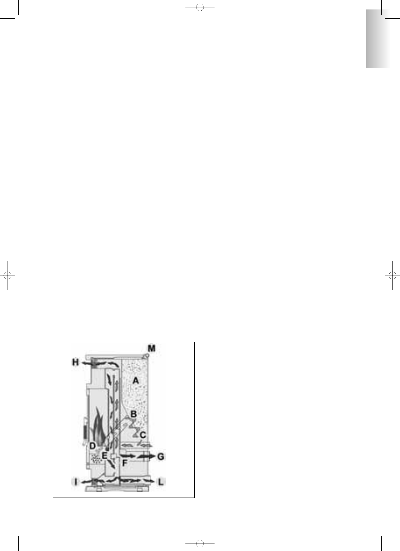
PRINCIPE DE FONCTIONNEMENT
Les poêles SOLEIL - TANIA - POLARIS (version de base ou
canalisable) utilisent comme combustible les pellets, dont la
combustion est gérée électroniquement. Nous illustrons leur fon-
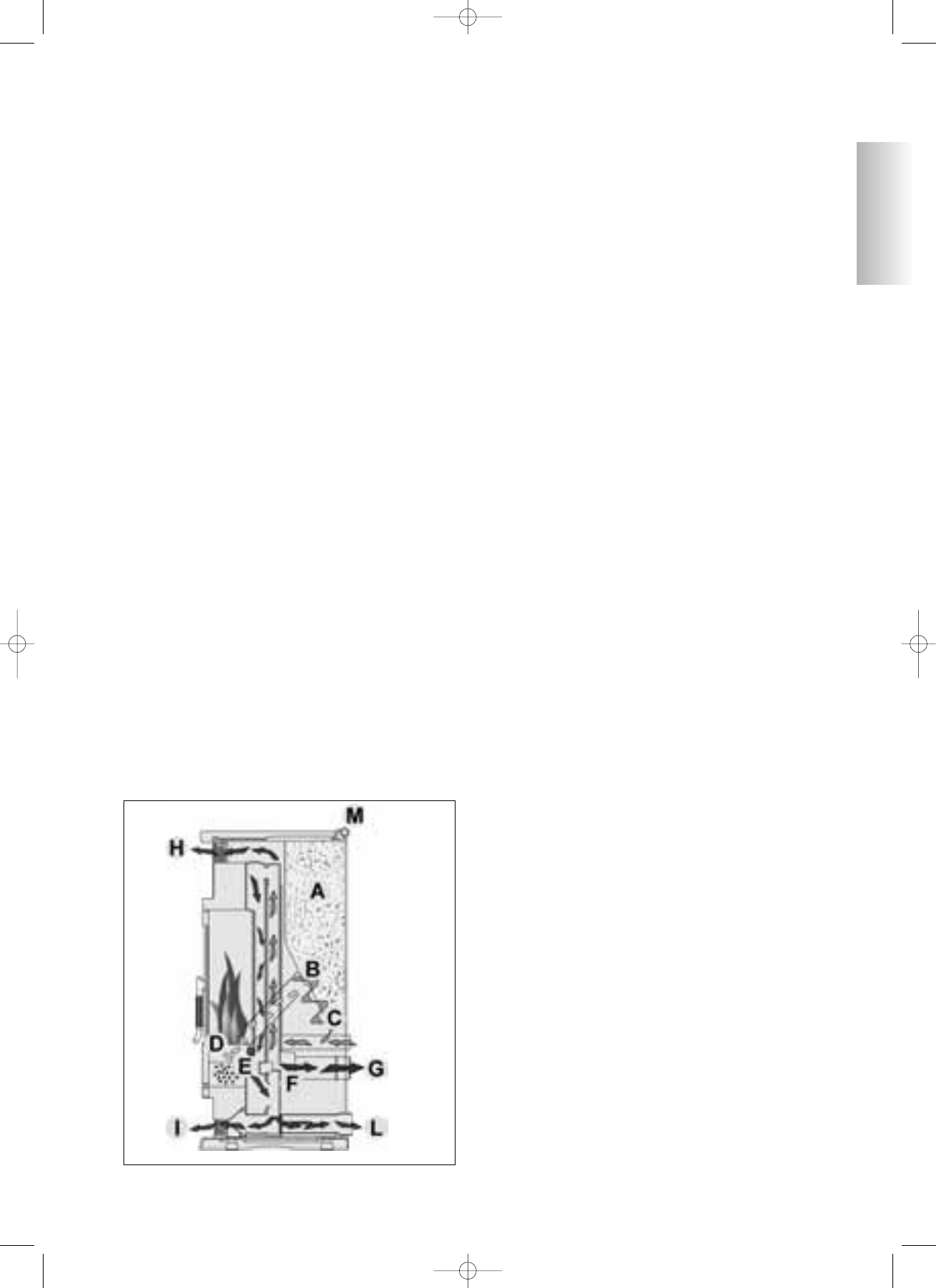
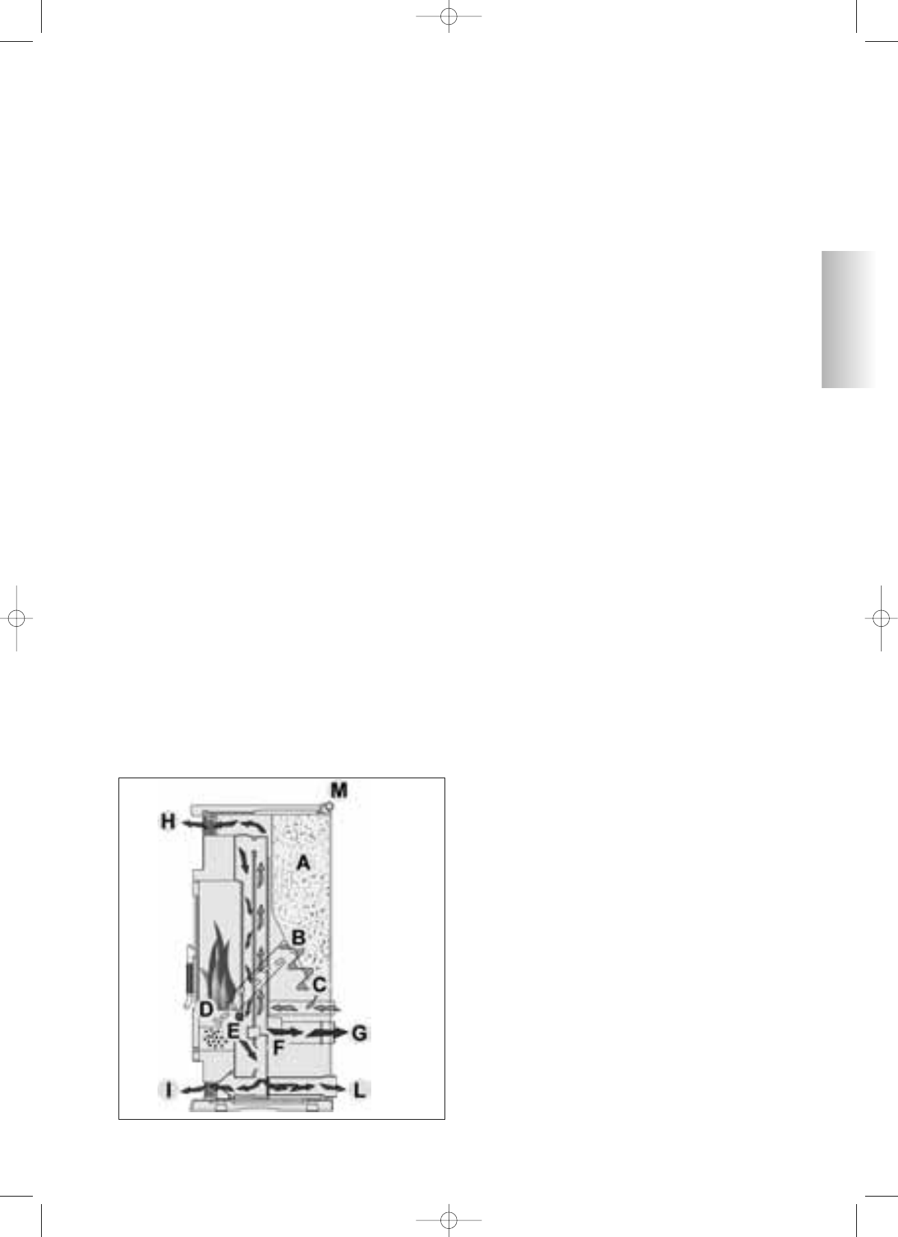
ctionnement ci-dessous. Les lettres font référence à la figure 1. Le
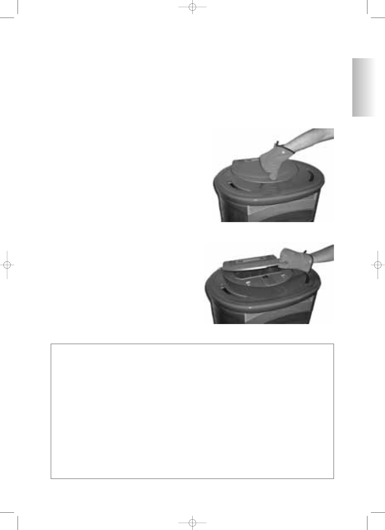
combustible (pellet) est prélevé du réservoir de stockage (A) et,
au moyen d’une vis sans fin (B) activée par un motoréducteur
(C), il est transporté dans le creuset de combustion (D).
L’allumage des pellets a lieu à travers l’air chaud produit par une
résistance électrique (E), et il est aspiré dans le creuset par le biais
d’un ventilateur centrifuge (F). Les fumées produites par la com-
bustion, sont extraites du foyer à travers ce même ventilateur cen-
trifuge (F), et expulsées par la bouche (G) située dans la zone
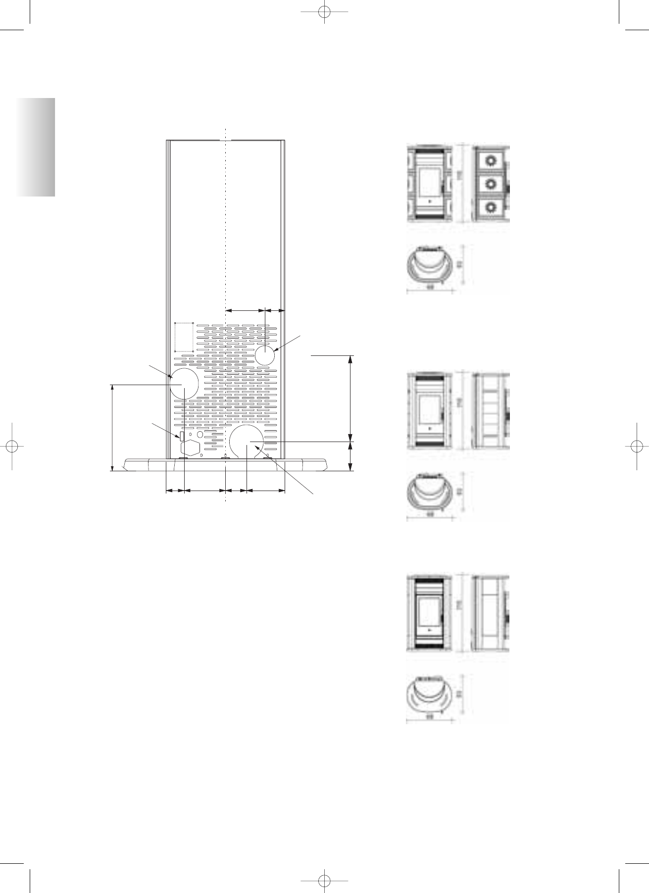
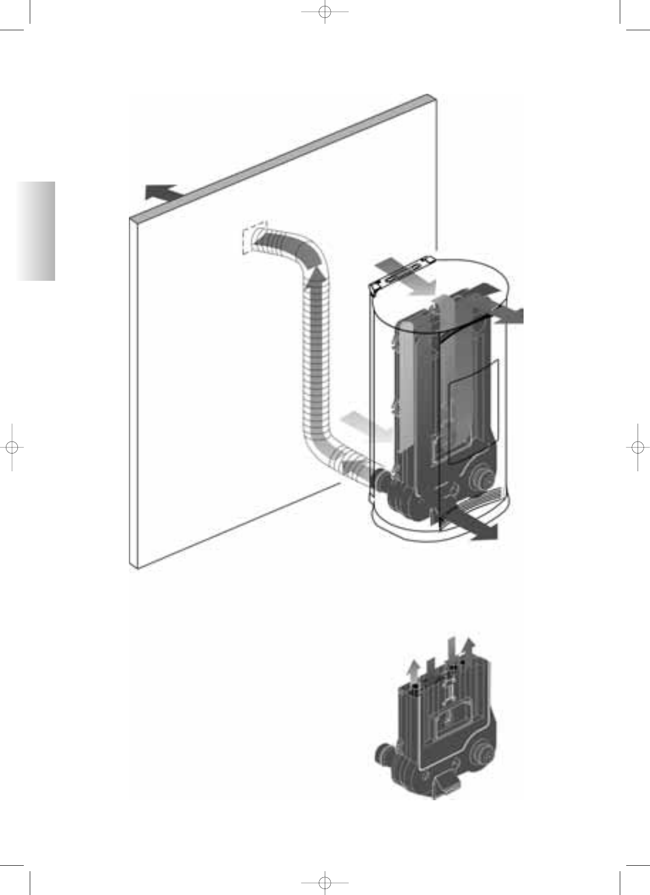
basse de la partie arrière du poêle. L’air de chauffage suit deux
parcours distincts dans les deux parties droite et gauche du poêle
(fig. 2 page 52). Dans la moitié droite du poêle, l’air entre dans la
partie supérieure pour passer dans l’interstice sur la partie arrière
du foyer, où il se chauffe pour sortir ensuite dans l’environnement
par la grille frontale supérieure (H), réf. circuit A (fig. 2 page 52).
Dans la moitié gauche du poêle, l’air entre dans la partie inférieu-
re pour passer (d’abord dans le sens ascendant, puis dans celui
descendant) dans l’interstice sur le dos du foyer, où il se chauffe
pour sortir ensuite dans l’environnement par la grille frontale
inférieure (I) ou (version canalisée) par la bouche de canalisation
postérieure. De la bouche, avec des tuyaux spéciaux, l’air peut
être convoyé dans une pièce adjacente (L), réf. circuit A (fig. 2
page 52). Dans la moitié droite du poêle, l’air entre dans la partie
supérieure pour passer (d’abord dans le sens descendant, puis
dans le sens ascendant) où il se chauffe pour sortir ensuite dans
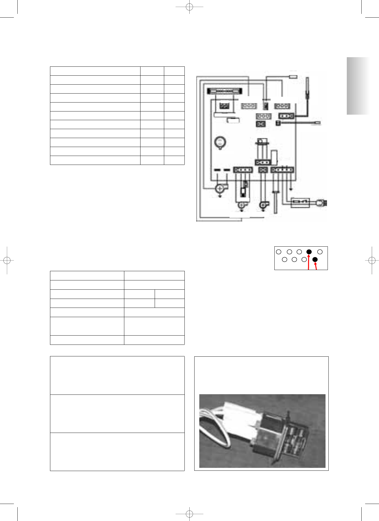
l’environnement par la grille frontale supérieure. Le réglage de la
quantité de combustible et l’extraction des fumées/alimentation
d’air comburant s’effectuent par le biais d’une carte électronique
dotée d’un software avec système Fire Control, afin d’obtenir
une combustion à haut rendement et basses émissions. Sur la par-
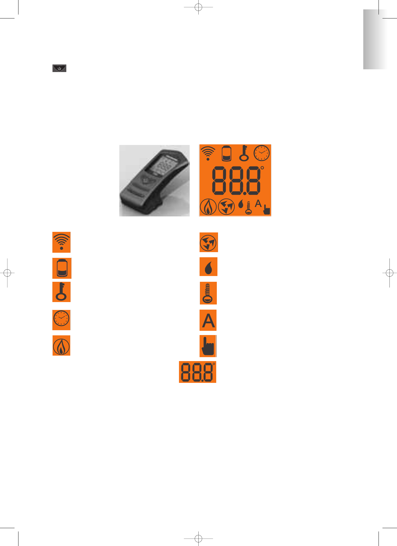
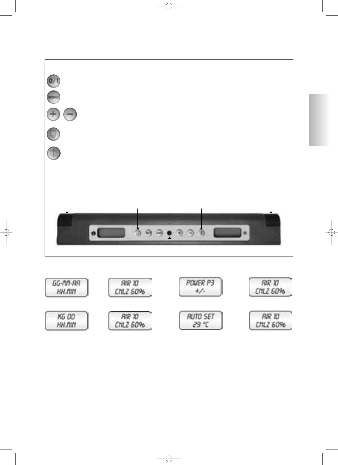
tie frontale supérieure est installé le tableau synoptique qui per-
met la gestion et la visualisation de toutes les phases du fonction-
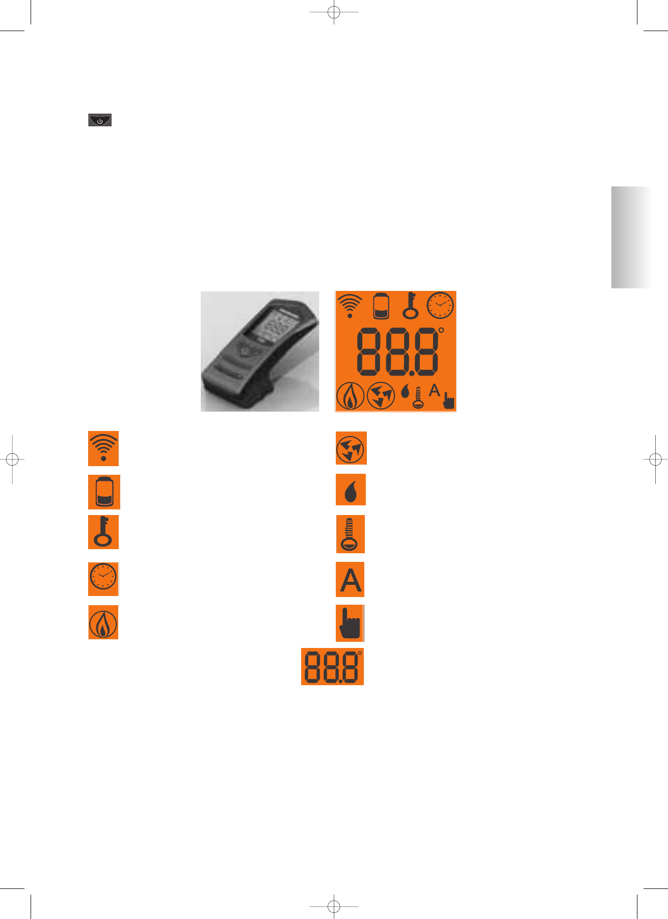
nement. Les principales phases peuvent également être gérées
avec la télécommande.Le poêle est doté d’une prise sérielle à
l’arrière (avec câble en option cod. 621240) pour le raccorde-
ment avec des dispositifs d’allumage à distance (par exemple
un combinateur téléphonique ou un thermostat d’ambiance).
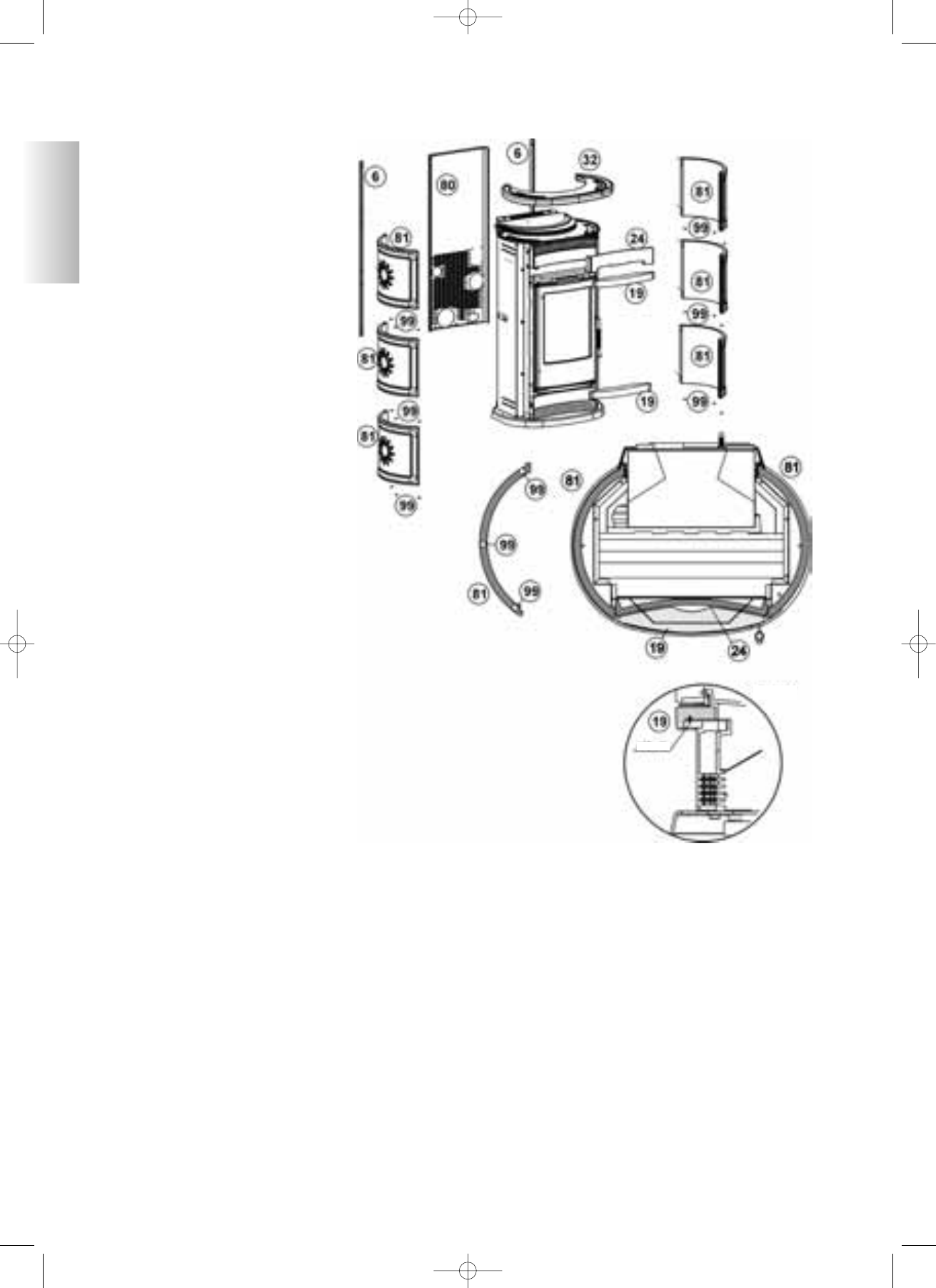
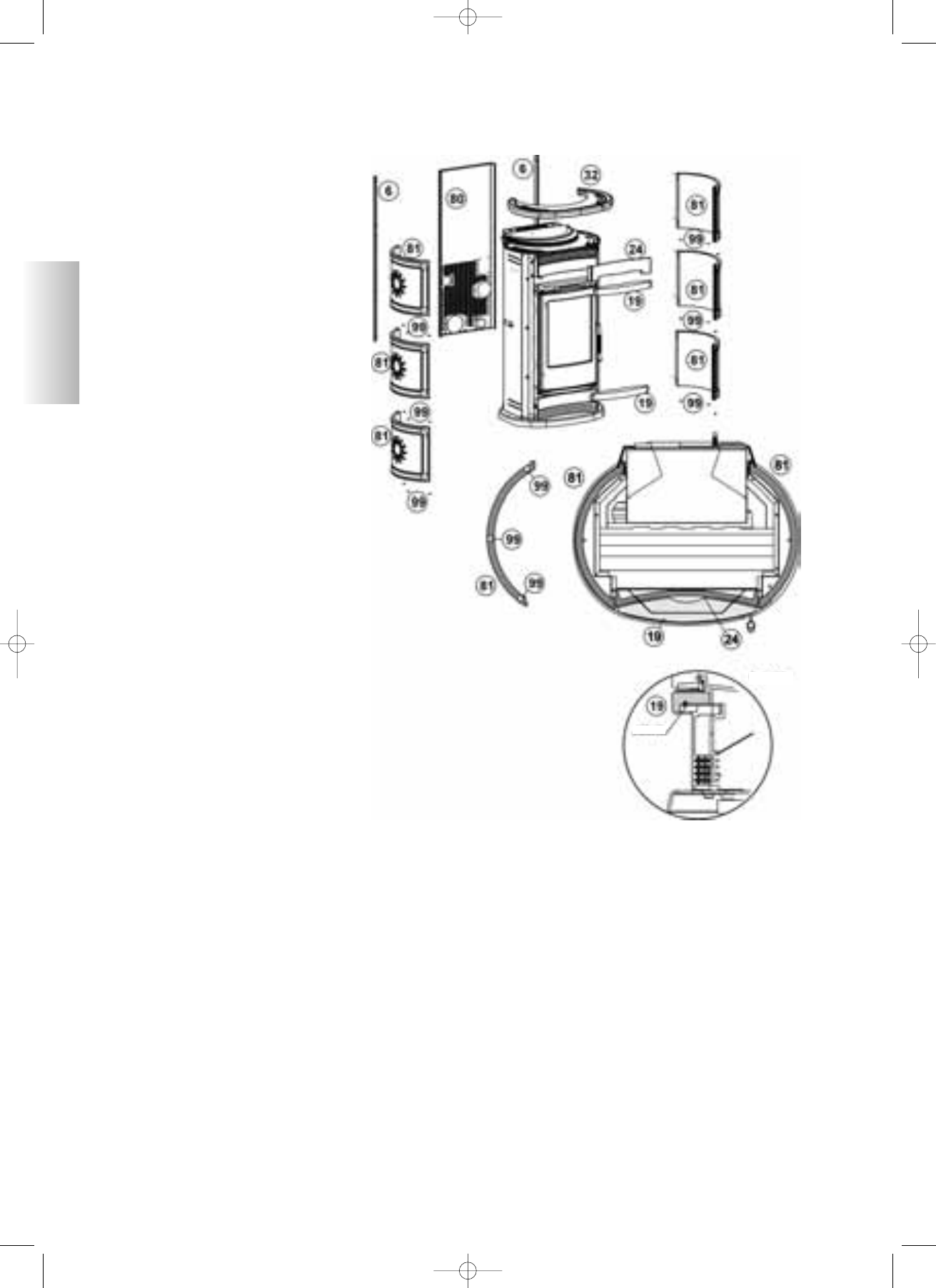
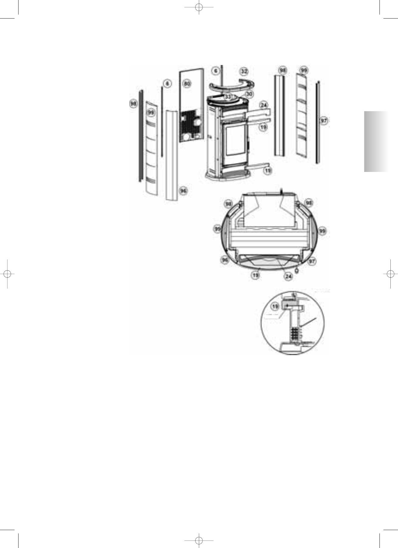
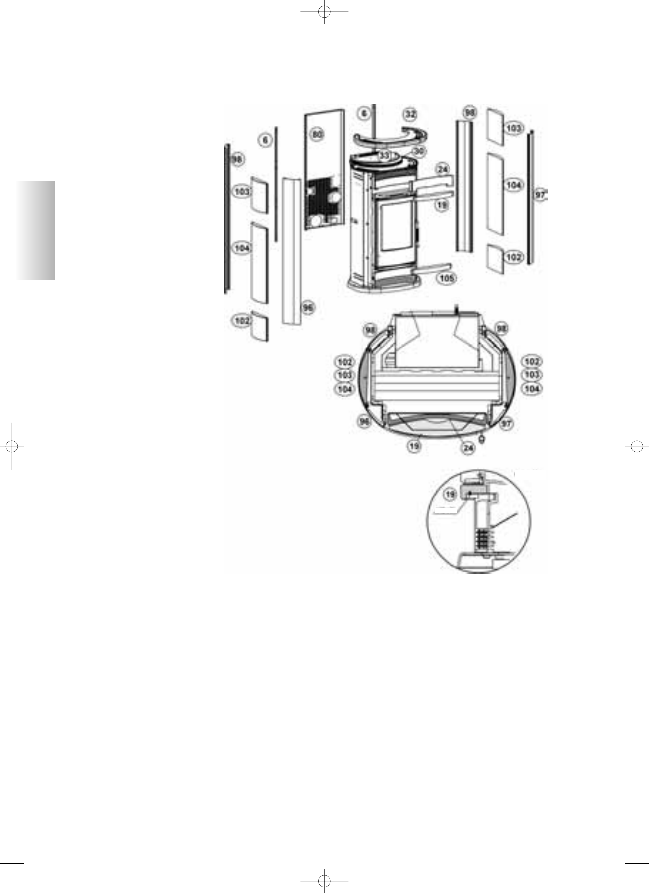
Les poêles sont réalisés avec une structure interne complètement
en fonte. Les deux versions disponibles sont:
• base,
• canalisable.
INFORMATIONS POUR LA SÉCURITÉ
Les poêles SOLEIL - TANIA - POLARIS ont été
conçus pour chauffer, à travers la combustion
automatique des pellets dans le foyer, la pièce dans
laquelle ils se trouvent, par irradiation et grâce au
mouvement de l’air sortant des grilles frontales, avec
possibilité de réchauffer la pièce attenante à travers
le mouvement de l’air canalisable par la bouche
située sur la partie arrière.
Les seuls risques pouvant dériver de l’emploi du
poêle, sont liés à un manque de respect de l’installation ou
à un contact direct avec les parties électriques sous tension
(internes), à un contact avec le feu et avec les parties chau-
des (verre, tuyaux, évacuation de l’air chaud) ou à l’intro-
duction de substances étrangères.
Comme combustible, utiliser exclusivement des pellets de
bois.
En cas de dysfonctionnement des composants, le poêle est
doté de dispositifs de sécurité qui garantissent son extin-
ction, à laisser avoir lieu sans intervenir.
Pour qu’il fonctionne régulièrement, le poêle doit
être installé conformément aux instructions contenues
dans cette fiche et, durant le fonctionnement, sa porte ne
doit pas rester ouverte:
en effet, la combustion est gérée automatiquement et
elle ne nécessite d’aucune intervention.
Il est impérativement interdit d’introduire des substances
étrangères dans le foyer ou dans le réservoir.
Pour le nettoyage du canal de fumée (segment de
carneau qui relie la bouche de sortie des fumées du
poêle au carneau) ne pas utiliser de produits inflammables.
Les parties du foyer et du réservoir doivent être
uniquement aspirées avec un aspirateur.
Le verre peut être nettoyé à FROID, avec un produit
spécial (ex. Glasskamin) et un chiffon.
Ne pas nettoyer à chaud.
S’assurer que le poêle a été installé et allumé par le
revendeur agréé selon les indications de la présente fiche.
Durant le fonctionnement du poêle, les tuyaux d’évacuation
et la porte atteignent des températures élevées.
Ne pas placer des objets ne résistant pas à la chaleur
à côté du poêle.
Ne JAMAIS utiliser des combustibles liquides pour
allumer l’insert ou raviver les braises.
Ne pas boucher les fentes d’aération du local d’installation,
ni les entrées d’air du poêle.
Ne pas mouiller le poêle et ne pas s’approcher des
parties électriques avec les mains mouillées.
Ne pas insérer des réducteurs sur les tuyaux d’évacuation
des fumées.
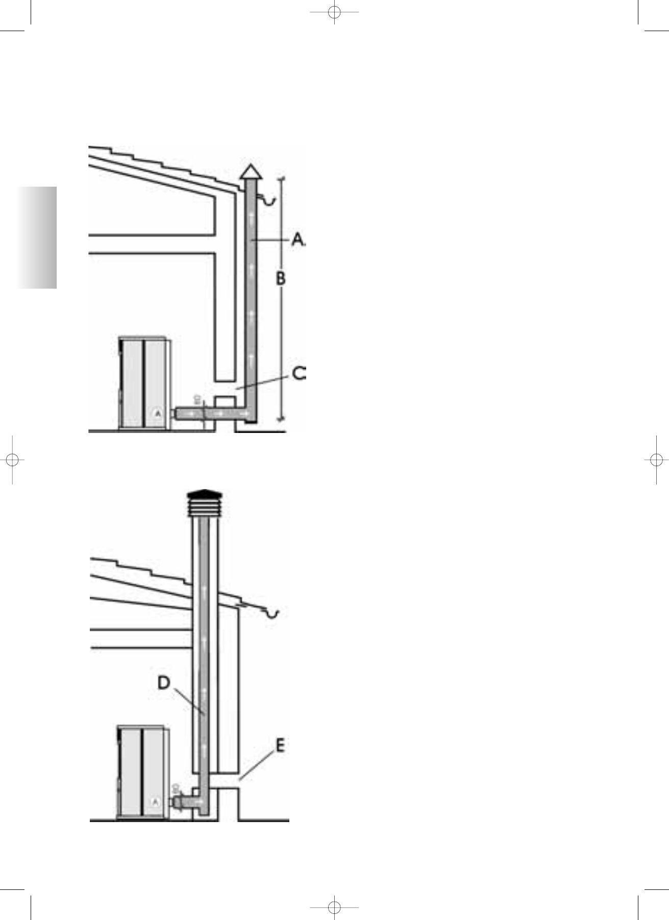
Le poêle doit être installé dans des locaux adaptés à
la prévention anti-incendie et desservis par tous les
services (alimentation et évacuations) nécessaires au
poêle pour un fonctionnement correct et en sécurité.
Fig. 1
sk tecnica soleil-polaris-tania multilingua_fra ristampa febbraio 2010.qxp 24/02/2010 9.10 Pagina 52
FRANÇAIS
52
CIRCULATION DE L’AIR CHAUD
A
B
A
B
Fig. 2
sk tecnica soleil-polaris-tania multilingua_fra ristampa febbraio 2010.qxp 24/02/2010 9.10 Pagina 53
FRANÇAIS
53
CANALISATION
(SEULEMENT pour VERSION CANALISABLE)
Le poêle présente une bouche sur la partie arrière (voir
son positionnement à la page 54 ENCOMBREMENTS)
pour la canalisation de l’air dans la pièce voisine à
travers le kit 8 spécial en option (code 297360)
composé:
• d’un collier serre-tube
• d’un tuyau flexible Ø 10 longueur 1,5m
• d’une bouche
Ou le Kit 9 pour la canalisation dans deux pièces
voisines, composé de:
• 2 gaines flexibles Ø 10, longuer 1,5 m.
• 4 colliers de serrage Ø 14 cm
• 2 kit manchons de raccordement Ø 10 cm
• culotte en Y Ø 10 cm.
Rappelons l’importance d’un calorifugeage opportun du
tuyau de passage de l’air chaud, pour éviter des dispersions.
Il faudra éviter le plus possible les coudes du tuyau.
Le temps et l’intensité de la distribution de l’air canalisé
se règle à partir du tableau synoptique (voir page 61).
Ce qui signifie que l’air peut être acheminé soit dans la
partie basse frontale, soit dans la partie postérieure
(référence figure 2 page 52).
NOTE
Si vous désirez transformer la version de base en version
canalisable, contactez votre revendeur et le revendeur et
achetez le kit spécial (code 297350), à installer et relier à
l’intérieur du poêle.
Dans la version de base NON canalisée, l’air chaud
sort par la grille frontale supérieure, demi-partie
droite et par la grille frontale inférieure demi-partie
gauche.
CHARGEMENT DES PELLETS DANS LE
RÉSERVOIR
Le couvercle du réservoir s’ouvre et se ferme à travers un
système pratique clik-clak, en exerçant une légère
pression sur le couvercle en fonte. (fig. 3).
ATTENTION : utiliser le gant spécial fourni lorsque
vous chargez le poêle alors qu’il est en fonction, donc
chaud.
Fig. 3
Fig. 4
NOTE sur le combustible.
Ces poêles sont conçus et programmés pour brûler des pellets bois de diamètre 6 mm.
Le pellet est un combustible qui se présente sous forme de petits cylindres d’environ 6 mm de diamètre, obtenus en compressant
la sciure à de hautes valeurs, sans utilisation de colles ou d’autres matériaux étrangers.
Il est commercialisé en sacs de 15 kg.
Pour NE PAS compromettre le fonctionnement des poêles, il est indispensable de NE PAS y brûler autre chose que des pellets.
L’emploi d’autres matériaux (bois compressé), détectable par des analyses de laboratoire, implique l’invalidation de la garantie.
Edilkamin a conçu, testé et programmé ses produits pour qu’ils garantissent leurs meilleures performances avec des pellets ayant
les caractéristiques suivantes:
diamètre: 6 - 7 millimètres
longueur maximum: 40 mm
humidité maximum: 8 %
rendement calorique: au moins 4300 kcal/kg
L’emploi de pellets ayant des caractéristiques différentes implique la nécessité d’un nouvel étalonnage des poêles, semblable à
celui réalisé par le revendeur lors du premier allumage.
L'emploi de pellets non adaptés peut provoquer une diminution du rendement, des anomalies de fonctionnement, des arrêts par
obstruction, l’encrassement du verre, des imbrûlés....
Une simple analyse du pellet peut être réalisée visuellement.
Bonne qualité: lisse, longueur régulière, peu poudreux.
Mauvaise qualité: avec des fentes horizontales et verticales, très poudreux, longueur très variable avec présence de corps étrangers.
sk tecnica soleil-polaris-tania multilingua_fra ristampa febbraio 2010.qxp 24/02/2010 9.10 Pagina 54
54
29
6
13.7
7 12.7
10
28.5
13
6.7
Ventilazione
Forzata
Ø 100 mm
Uscita fumi
Ø80mm
Aria
Combustione
Ø 40mm
Attacco
per presa
seriale Rs232
MODÈLES ET DIMENSIONS
sortie fumées
Ø 80mm
Fixation
fiche série
Rs232
air
combustion
Ø 40mm
ventilation
forcée
Ø 100mm
Le produit est fabriqué conformément aux directives
suivantes:
89/106 CEE (CPD) matériaux de construction
73/23 CEE (LVD) sécurité électrique
37/98 CEE machines
2004/108 CEE (EMC) compatibilité électromagnétique
et selon les normes:
EN14785
EN60335.1 EN50165 EN50366
EN55014.1 EN55014.2 EN61000-3-2 EN61000-3-3
SOLEIL
Céramique rouge, ambre ou blanc moucheté
TANIA
Acier gris
POLARIS
Pierre ollaire
FRANÇAIS
sk tecnica soleil-polaris-tania multilingua_fra ristampa febbraio 2010.qxp 24/02/2010 9.10 Pagina 55
55
CARACTÉRISTIQUES THERMOTECHNIQUES
CARACTÉRISTIQUES ÉLECTRIQUES
CARTE ÉLECTRONIQUE
Capacité réservoir 29 kg
Rendement 89,1 %
Puissance utile max 12 kW
Autonomie (min/max) 11/23 heures
Consommation combustible (min/max) 1,25/2,7 kg/h
Volume de chauffe* 300
m
³
Poids SOLEIL avec emballage** 282/288 kg
Poids TANIA avec emballage** 267/273 kg
Poids POLARIS avec emballage** 296/302 kg
Diamètre conduit fumées (mâle) 80 mm
Diamètre conduit prise air (mâle) 40 mm
Alimentation 230Vac +/- 10% 50 Hz
Interrupteur on/off oui
Puissance moyenne absorbée 100 W
Puissance absorbée à l’allumage 400 W
Fréquence télécommande (de série) Infrarouges
Protection sur alimentation
générale*
Fusible 2A, 250 Vac 5x20
Protection sur carte électronique Fusible 2A, 250 Vac 5x20
THERMOCOUPLE: situé sur l’évacuation des fumées, il
en détecte la température. Il contrôle la phase d’allumage,
de travail et d’extinction en fonction des paramètres
programmés.
CAPTEUR DE FLUX D’AIR: situé dans le canal
d’aspiration, il intervient lorsque le flux de l’air comburant
n’est pas correct, en provoquant des problèmes de
dépression dans le circuit des fumées.
THERMOSTAT DE SÉCURITÉ: il intervient lorsque la
température à l’intérieur du poêle est trop élevée. Il arrête
le chargement des pellets en provoquant l’extinction du
poêle.
Les données mentionnées ci-dessus sont indicatives.
EDILKAMIN s.p.a. se réserve le droit de modifier ses
produits sans préavis, pour améliorer leurs performances.
DISPOSITIFS DE SÉCURITÉ
FUSIBLE
* deux fusibles sont montés sur la prise avec
interrupteur, située sur la partie arrière du
poêle, dont un est fonctionnel et l’autre de réserve.
FRANÇAIS
** base/canalisable
* Le volume de chauffe est calculé compte tenu de l'utilisation
de pellets avec un p.c.i. d'au moins 4300 kcal/kg et une isolation
de la maison conforme à la Loi 10/91, et modifications succes-
sives et une demande de chaleur de 35 kcal/m³ par heure.
Il est important de tenir compte aussi de la position du poêle
dans la pièce.
PORT SÉRIE
Sur le port AUX (contact libre
sur les pins), vous pouvez faire
installer par le Revendeur un
dispositif en option permettant le
contrôle de l’allumage et de l’extinction (par exemple un
combinateur téléphonique ou un thermostat d’ambiance),
placé derrière le poêle. Peut être connecter avec le cheva-
let fourni en option prévu à cet effet (cod. 621240).
BATTERIE TAMPON
Une batterie tampon (type CR 2032 de 3 Volts) se trouve
sur la carte électronique. Son dysfonctionnement (non
considéré comme un défaut de produit, mais comme
l’usure normale) est indiqué par ERREUR RTC RD. Pour
plus de références le cas échéant, contacter le Revendeur
qui a effectué le 1er allumage.
pin 2
pin 6
AUX
RPM VENTILA-
TEUR PIÈCE
RPM VENTILATEUR
CANALISÉE
CAPTEUR FLUX
THERMOCOUPLE T°
FUMÉES
RPM FUMÉES
PANNEAU COMMANDES
Service
IÉLÉMENT ALLUMAGE
CAPTEUR AIR
AMBIANT
VENTILATION
CANALISÉE
PRISE ARRIÈRE POÊLE
2A FUSIBLE
VIS SANS FIN
MOTEUR
EXPULSION
FUMÉES
TRAPPE
RÉSEAU 230 VAC
batterie tampon
2A FUSIBLE
VENTILATION PIÈCE
sk tecnica soleil-polaris-tania multilingua_fra ristampa febbraio 2010.qxp 24/02/2010 9.10 Pagina 56
56
Montage Revêtements SOLEIL
Desserrer la partie arrière (80) et les deux profils (6) insérer les carreaux (81) sur le
côté droit. Les carreaux caractéristiques, réalisés par coulage, pourraient s’avérer
légèrement différents en hauteur l’un de l’autre.
Pour remédier à une éventuelle variation de hauteur, on pourra intercaler les caout-
choucs fournis sans porter aucunement préjudice à l’esthétique du poêle. Intercaler 3
caoutchoucs (99) entre deux plaques en partant de la base, remonter ensuite le profil
(6) et répéter la même opération sur le côté gauche.
Dans les emboîtures prévues dans la grille frontale, insérer l’élément frontal postérieur
(24) et mettre ensuite en place l’élément frontal avant (19) en l’emboîtant dans le bac
humidificateur et en le siliconant. Mettre en place le haut (32).
Positionner le second frontal avant (19) et le fixer ensuite avec deux vis, de la manière
indiquée dans le détail ”X”.
NOTE: l’émail rouge avec poudre cristalline, appliqué sur la faïence, craquelle
uniformément (craquelures) sur toute la surface.
Ces craquelures ne sont pas un défaut, mais une caractéristique de l’émail appliqué sur
la faïence. Les éléments en céramique (faïence) sont coulés et émaillés à la main et ils
peuvent présenter de petites imperfections qui ne portent aucun préjudice à leur qualité
(petits creux ou porosité de l’émail).
INSTRUCTIONS UTILISATION
KIT MATÉRIEL
Le kit du matériel fourni avec le
set documentation se compose
de:
2 vis M6x25
2 vis M6x12
4 entretoises en silicone pour céramique
haut 8 rondelles plates diam. 6
Mode d’emploi:
1. Utiliser les 2 vis M6x25 et les
2 rondelles plates M6 pour fixer
l’élément frontal supérieur en céramique.
2. Utiliser les 2 vis M6x12 et les 2
rondelles plates M6 pour fixer l’élément
frontal inférieur en céramique.
3. pour les 4 entretoises et les 4
rondelles, suivre la séquence:
• insérer les 4 entretoises pour céramique
dans les 4 trous libres correspondants du
haut en fonte,
• appuyer le haut en céramique pour
vérifier la planéité correcte,
• si nécessaire, placer une rondelle plate
entre l’entretoise en céramique et le haut en
fonte, afin d’amener le haut en céramique à
plat avec le poêle.
FRANÇAIS
2 Visses
Part. “X”
sk tecnica soleil-polaris-tania multilingua_fra ristampa febbraio 2010.qxp 24/02/2010 9.10 Pagina 57
57
Montage Revêtements TANIA
Le poêle est livré monté. Cependant, en cas de nécessité de démonter le
revêtement, suivre la marche ci-dessous :
Desserrer la partie arrière (80) et les deux profils (6), démonter le couvercle (33),
le haut en fonte (30) et celui en céramique (32).
Dégager ensuite les flancs en métal (99) et, si nécessaire, dégager aussi les deux
profils en aluminium (98) emboîtés dans les pivots de la base.
Dégager le profil avant (19), puis retirer l’élément frontal postérieur supérieur
(24) des emboîtures dans la structure de la grille.
Pour retirer l’élément frontal avant inférieur (19) desserrer les deux vis.
Voir détail ”X”
Pour remonter, suivre la marche inverse de la dépose.
INSTRUCTIONS UTILISATION KIT MATÉRIEL
Le kit du matériel fourni avec le set documentation se compose de:
2 vis M6x25
2 vis M6x12
4 entretoises en silicone pour céramique haut
8 rondelles plates diam. 6
Mode d’emploi:
1. Utiliser les 2 vis M6x25 et les 2 rondelles plates M6 pour
fixer l’élément frontal supérieur en céramique.
2. Utiliser les 2 vis M6x12 et les 2 rondelles plates M6 pour
fixer l’élément frontal inférieur en céramique.
3. pour les 4 entretoises et les 4 rondelles, suivre la séquence:
• insérer les 4 entretoises pour céramique dans les 4 trous
libres correspondants du haut en fonte,
• appuyer le haut en céramique pour vérifier la planéité correcte
• si nécessaire, placer une rondelle plate entre l’entretoise
en céramique et le haut en fonte, afin d’amener le haut en
céramique à plat avec le poêle.
FRANÇAIS
2 Visses
Part. “X”
sk tecnica soleil-polaris-tania multilingua_fra ristampa febbraio 2010.qxp 24/02/2010 9.10 Pagina 58
58
Montage Revêtements POLARIS
INSTRUCTIONS UTILISATION KIT MATÉRIEL
Le kit du matériel fourni avec le set documentation se compose de:
4 vis M6x12
4 entretoises en silicone pour céramique haut
8 rondelles plates diam. 6
Mode d’emploi:
1. Utiliser les 2 vis M6x25 et les 2 rondelles plates M6 pour
fixer l’élément frontal supérieur en céramique.
2. Utiliser les 2 vis M6x12 et les 2 rondelles plates M6 pour
fixer l’élément frontal inférieur en céramique.
3. pour les 4 entretoises et les 4 rondelles, suivre la séquence:
• insérer les 4 entretoises pour céramique dans les 4 trous
libres correspondants du haut en fonte,
• appuyer le haut en céramique pour vérifier la planéité correcte
• si nécessaire, placer une rondelle plate entre l’entretoise
en céramique et le haut en fonte, afin d’amener le haut en
céramique à plat avec le poêle.
Le poêle est livré monté. Cependant, en cas de nécessité de démonter le
revêtement, suivre la marche ci-dessous :
Desserrer la partie arrière (80) et les deux profils (6), démonter le couvercle (33),
le haut en fonte (30) et celui en céramique (32).
Dégager ensuite les flancs en métal (99) et, si nécessaire, dégager aussi les deux
profils en aluminium (98) emboîtés dans les pivots de la base.
Dégager le profil avant (19), puis retirer l’élément frontal postérieur supérieur
(24) des emboîtures dans la structure de la grille.
Pour retirer l’élément frontal avant inférieur (19) desserrer les deux vis.
Voir détail ”X”.
Pour remonter, suivre la marche inverse de la dépose.
FRANÇAIS
2 Visses
Part. “X”
sk tecnica soleil-polaris-tania multilingua_fra ristampa febbraio 2010.qxp 24/02/2010 9.10 Pagina 59
59
MONTAGE ET INSTALLATION (REVENDEUR)
Pour tout ce qui n’est pas expressément indiqué, dans chaque pays, faire référence aux normes locales. En Italie, faire
référence à la norme UNI 10683/2005, ainsi qu’aux éventuelles indications régionales ou des DASS locales. En cas
d’installation dans une copropriété, demander au préalable l’autorisation du syndic de l’immeuble.
VÉRIFICATION DE COMPATIBILITÉ AVEC D’AUTRES DISPOSITIFS
Le poêle NE DOIT PAS être installé dans le même local où se trouvent des extracteurs et des appareils à gaz de type B.
VÉRIFICATION BRANCHEMENT ÉLECTRIQUE (POSITIONNER LA FICHE DANS UN POINT
ACCESSIBLE)
Le poêle est doté d’un cordon d’alimentation électrique à brancher à une prise de 230V 50 Hz, de préférence avec un
disjoncteur thermique. Des variations de tension supérieures à 10% peuvent compromettre le bon fonctionnement du
poêle (prévoir un interrupteur différentiel adapté, s’il n’est pas déjà monté). L'installation électrique doit être aux
normes; vérifier, en particulier, le bon état du circuit de mise à la terre. La ligne d’alimentation doit avoir une section
adaptée à la puissance de l’appareil.
Le mauvais état de marche du circuit de terre provoque un mauvais fonctionnement qu’Edilkamin ne peut prendre en
charge.
DISTANCES DE SÉCURITÉ POUR ANTI-INCENDIE ET POSITIONNEMENT
Pour un fonctionnement correct, l’insert doit être positionné perpendiculairement au sol.
Vérifier la capacité portante du sol.
Le poêle doit être installé dans le respect des conditions de sécurité suivantes:
- distance minimum sur les côtés et sur la partie arrière de 40 cm des matériels moyennement inflammables.
- ne placer aucun matériel facilement inflammable devant le poêle, à une distance inférieure à 80 cm.
En cas d’impossibilité de respecter les distances indiquées ci-dessus, mettre en place impérativement des dispositifs
techniques et de maçonnerie permettant d’éviter tout risque d’incendie.
En cas de connexion avec une paroi en bois ou d’un autre matériel inflammable, calorifuger adéquatement le tuyau
d’évacuation des fumées.
PRISE D’AIR
Il faudra impérativement prévoir, derrière le poêle, une prise d’air reliée à l’extérieur, d’une surface d’au moins 80
cm², garantissant au poêle une alimentation d’air suffisant pour la combustion.
ÉVACUATION DES FUMÉES
Le système d’évacuation doit être individuel pour le poêle (il est interdit d’évacuer les fumées dans un carneau
commun avec d’autres dispositifs).
L’évacuation des fumées a lieu par le tuyau de 8 cm de diamètre situé sur la partie arrière du poêle.
L’évacuation des fumées du poêle doit être reliée avec l’extérieur à l’aide de tuyaux d’acier adaptés, sans obstructions.
Le tuyau doit être scellé hermétiquement. Pour l’étanchéité des tuyaux et pour leur isolation éventuelle, utiliser
impérativement des matériaux résistants au moins à 300°C (silicone ou mastics pour hautes températures).
Le seul segment horizontal admis peut avoir une longueur jusqu’à 2 m et les coudes à 90° être au nombre de deux au
maximum.
Si l’évacuation ne s’insère pas dans un carneau, il faudra installer un segment vertical et un segment d’extrémité
antivent (référence UNI 10683/2005). Le conduit vertical peut être interne ou externe. Si le canal de fumée se trouve à
l’extérieur, il devra être adéquatement calorifugé.
Si le canal de fumée* s’insère dans un carneau, celui-ci doit être autorisé pour les combustibles solides et, si son
diamètre dépasse 150 mm, il faudra l’assainir en intubant et en scellant l’évacuation par rapport à la partie en
maçonnerie.
Tous les segments du canal de fumée* doivent pouvoir être inspectés. Si le conduit est fixe, il doit présenter des
ouvertures pour l’inspection et le nettoyage.
Pour l’installation, Edilkamin fournit des tuyaux adaptés (option) en vente chez votre revendeur.
Les installations possibles sont celles proposées aux figures de la page suivante.
FRANÇAIS
sk tecnica soleil-polaris-tania multilingua_fra ristampa febbraio 2010.qxp 24/02/2010 9.10 Pagina 60
60
FRANÇAIS
Les cheminées et les conduits de fumée auxquels sont
reliés les appareils qui utilisent des combustibles solides
doivent être ramonés tous les ans (vérifiez si dans votre
pays il existe une réglementation à cet égard).
En omettant le contrôle et un ramonage réguliers, on
augmente le risque d’incendie dans la cheminée. Dans ce
cas, suivre la marche ci-dessous :
• ne pas utiliser de l’eau pour éteindre ;
• vider le réservoir à pellets ;
• après l’incident, faire appel à des techniciens spécialisés
avant de redémarrer la machine.
A: carneau en acier calorifugé
B: hauteur minimum 1,5m
C-E: prise d’air de l’environnement (section passante
minimum 80 cm²)
D: carneau en acier à l’intérieur du carneau, existant en
maçonnerie.
INSTALLATIONS POSSIBLES
Fig. 2
Fig. 1
sk tecnica soleil-polaris-tania multilingua_fra ristampa febbraio 2010.qxp 24/02/2010 9.10 Pagina 61
61
FRANÇAIS
L’INTERFACE
AFFICHAGES POSSIBLES
TABLEAU SYNOPTIQUE
appuyer pendant 2” pour allumer et éteindre
pour accéder au menu
pour augmenter / diminuer les différents réglages
(touche chargement pellets/réserve), lorsqu’on l’appuie une fois elle “informe” la mémoire des poêles qu’un
sachet de 15 kg de pellets a été chargé, en permettant donc de garder le calcul pour la réserve (voir page sui vante)
(touche réglage canalisation) permet la gestion du flux d’air chaud dans la canalisation, en association avec
les touches +/-
Bouton Droit: pour varier la ventilation (de 1 à 10)
Bouton Gauche: pour varier la puissance (de 1 à 5)
L’AFFICHEUR Droit indique le niveau de ventilation et de canalisation.
L’AFFICHEUR Gauche indique le niveau de puissance ou la température et la réserve ou la date et l’heure.
Bouton pour puissance
en STAND-BY en AUTOMATIQUE
en MANUEL
Bouton ventilation
Chargement pellets /réserve
Récepteur TélécommandAfficheur Gauche Afficheur Droit
Canalisation
sk tecnica soleil-polaris-tania multilingua_fra ristampa febbraio 2010.qxp 24/02/2010 9.10 Pagina 62
62
FRANÇAIS
FONCTIONNEMENT
Avant l’allumage.
1°Allumage: contacter le revendeur, qui étalonnera votre poêle selon le type de pellets que vous utilisez et les conditions
d’utilisation.
Les premiers allumages peuvent donner lieu à de légères odeurs de peinture qui disparaissent très rapidement.
Avant de procéder à l’allumage, vérifier:
==> L’installation correcte.
==> L’alimentation électrique.
==> La fermeture de la porte, qui doit être étanche.
==> La propreté du creuset.
==> La présence, à l’afficheur, de l’indication de stand-by (date puissance ou température clignotant).
Remplissage de la vis sans fin.
Au cas où le réservoir à pellets se viderait complètement, pour remplir la vis sans fin, appuyer en même temps sur les
touches + et (sur la télécommande ou sur le tableau synoptique) pendant quelques secondes. Relâcher ensuite les
touches, à l’afficheur s’inscrit CHARGEMENT-LOAD.
Cette opération doit être effectuée avant l’allumage, si le poêle s’est arrêté à cause d’un manque de pellets.
Il est normal qu’une certaine quantité de pellets, que la vis ne parvient pas à aspirer, demeure dans le réservoir.
Une fois par mois, aspirer complètement le réservoir pour éviter l’accumulation de résidus poudreux.
POUR ALLUMER
Allumage automatique
Le poêle étant en stand-by, appuyer pendant 2" sur la touche 0/1 (sur le tableau synoptique ou sur la télécommande)
pour démarrer la procédure d’allumage, afficher l’inscription Start et un compte à rebours en secondes (1020).
Toutefois, la phase de réglage n’est pas à temps prédéterminé : sa durée est automatiquement abrégée si la carte relève
que quelques tests ont été surmontés avec succès). Après environ 5 minutes, la flamme apparaît.
Allumage manuel
Si la température est inférieure à 3°C et qu’elle ne permet pas à la résistance électrique de se chauffer au rouge, ou en
cas de dysfonctionnement temporaire de la résistance, on pourra allumer manuellement le poêle avec un allume-feu.
Pour ce faire, introduire dans le creuset un morceau d’allume-feu bien embrasé, fermer la porte et appuyer sur 0/1 sur
le tableau synoptique ou sur la télécommande.
MODE DE FONCTIONNEMENT
Le poêle peut fonctionner de deux manières:
Manuelle: l’utilisateur programme la puissance de travail désirée (de 1 minimum, à 5 maximum)
Automatique: l’utilisateur programme la température désirée dans la pièce et, en la lisant, le poêle module la puissance
pour atteindre la même température, en se positionnant à la puissance 1 lorsque la température a été obtenue.
Fonctionnement manuel à partir du tableau synoptique/télécommande
Lorsque le poêle est en fonction ou en stand-by, appuyer une fois sur la touche Menu sur le tableau synoptique/télé-
commande pour afficher l’inscription POWER (avec la puissance à laquelle le poêle est en train de
travailler), tourner le bouton gauche ou appuyer sur la touche + da télécommande pour augmenter la puissance de
fonctionnement du poêle (de POWER 1 à POWER 5).
Réglage de la ventilation sur le tableau synoptique
Pour régler, tourner le bouton droit, lorsque le poêle est en fonction ou en stand-by, la ventilation (de 1 à 10 dans toutes
les puissances).
Fonctionnement automatique à partir du tableau synoptique / télécommande
Appuyer sur la touche Menu 2 fois pour commuter du fonctionnement manuel au fonctionnement automatique, en
réglant la température que l’on désire atteindre dans la pièce (pour régler la température de 10°C à 29°C, utiliser les
touches + et avec la télécommande ou avec le bouton gauche du tableau) et le poêle règle la puissance de travail
pour l’atteindre (PUISSANCE P 5 ou la conserver PUISSANCE P 1).
En cas de programmation d’une température inférieure à celle de la pièce, le poêle travaille en P1.
sk tecnica soleil-polaris-tania multilingua_fra ristampa febbraio 2010.qxp 24/02/2010 9.10 Pagina 63
63
FRANÇAIS
Extinction
Pour un confort accru, le poêle s’éteint avec les ventilateurs de l’air ambiant à la même puissance à laquelle il
travaillait.
Le poêle étant en fonction, appuyer pendant 2" sur la touche 0/1 (sur le tableau synoptique ou sur la télécommande)
pour mettre en route la procédure d’extinction et afficher le compte à rebours, variable selon la puissance à laquelle la
phase d’extinction a été entamée.
La phase d’extinction (dont l’objectif est d’éteindre la flamme, ne pas laisser d’imbrûlés dans le creuset et refroidir le
poêle) prévoit :
• Interruption chute pellets.
• Ventilation active au niveau où le poêle fonctionnait..
• Moteur d’évacuation des fumées actif.
Ne jamais débrancher
la fiche durant l’extinction.
RÉGLAGES
Réglage horloge
Appuyer pendant 2 " sur la touche Menu et, en suivant les indications à l’afficheur, avec les touches + et , on
accède au Menu “montre/clock”. Cette touche permet de programmer l’horloge interne de la carte électronique.
L’appui en succession sur la touche Menu, affiche en séquence les données suivantes pour permettre leur réglage :
Jour, Mois, Année, Heure, Minutes, Jour de la semaine.
L’inscription Sauvegardé?? à valider avec Menu permet de vérifier l’exactitude des opérations effectuées avant de les
valider
(l’indication Sauvegardé s’inscrit alors à l’afficheur).
Programmateur d’allumage et d’extinction horaires durant la semaine
Appuyer pendant 2 secondes sur la touche Menu de la télécommande pour accéder au réglage de l’horloge et appuyer
sur la touche + pour accéder à la fonction de programmation horaire hebdomadaire, identifiée à l’afficheur par la
description "Program./on-off".
La programmation permet de programmer un nombre d’allumages et d’extinctions par jour (jusqu’à un maximum de
trois) pour chaque jour de la semaine.
Valider à l’afficheur avec la touche "Menu" pour afficher une des possibilités suivantes:
NO PROGR (aucun programme programmé)
PROGRAM/UNIQUE (un programme unique pour tous les jours)
PROGRAM/JOUR (programmation pour chaque jour)
Pour passer d’une fonction à l’autre, appuyer sur les touches + et .
Valider, avec la touche Menu l'option "PROGRAM/UNIQUE" pour accéder au choix du nombre de programmes
(allumages/extinctions) pouvant être effectués en un jour.
Avec "PROGRAM/UNIQUE" le ou les programmes déterminés seront les mêmes pour tous les jours de la semaine.
Appuyer successivement sur + pour afficher:
- No progr
- 1° progr (un allumage et une extinction par jour), 2° progr (idem), 3° progr (idem)
Intervenir sur la touche pour afficher dans l’ordre inverse.
Sélectionner 1° programme pour afficher l’heure de l’allumage.
L’afficheur visualise: 1 ON heures 10,30; appuyer sur la touche +/ – pour changer l’heure et valider avec Menu.
L’afficheur visualise: 1 ON minutes 10,30; appuyer sur la touche +/ – pour varier les minutes et valider avec Menu.
Suivre la même marche pour régler l’heure des extinctions. Valider le programme en appuyant sur la touche Menu
lorsque l’indication “Sauvegardé” s’inscrit à l’afficheur.
En validant avec "PROGRAM/JOUR, il faudra choisir le jour où effectuer la programmation:
1 Lu ; 2 Ma; 3 Me; 4 Je; 5 Ve; 6 Sa;7 Di
Après avoir sélectionné le jour, en les faisant défiler avec les touches + et et avoir validé avec la touche Menu, on
continuera la programmation de la même manière avec laquelle on effectue un "PROGRAM/UNIQUE", la
programmation continue avec le même mode que pour un "PROGRAM/UNIQUE", en sélectionnant, pour chaque jour
de la semaine, si activer une programmation en établissant le nombre d’interventions et à quelle heure.
En cas d’erreur à n’importe quel moment de la programmation, on pourra quitter le programme sans enregistrer.
L’appui sur la touche 0/1 affiche Sauvegardé.
Note sur la variabilité de la flamme
Les variations éventuelles de l’état de la flamme dépendent du type de pellets utilisés, ainsi que d’une variabilité
normale de la flamme du combustible solide et des nettoyages périodiques du creuset, que le poêle effectue
automatiquement.
N.B. les nettoyages automatiques effectuées par le poêle ne remplacent pas la nécessaire aspiration à froid faite par
l’utilisateur avant l’allumage).
sk tecnica soleil-polaris-tania multilingua_fra ristampa febbraio 2010.qxp 24/02/2010 9.10 Pagina 64
FRANÇAIS
SIGNALISATION DE RÉSERVE DES PELLETS
Les poêles SOLEIL - TANIA - POLARIS sont dotés d’une fonction électronique de relèvement de la quantité de
pellets.
Le système de relèvement des pellets, intégré dans la carte électronique permet au poêle de contrôler à n’importe quel
moment du fonctionnement, combien il reste de kg de pellets avant l’épuisement de la charge effectuée.
Pour que le système fonctionne correctement, il est important de suivre la marche ci-dessous, lors du 1° allumage (qui
doit être effectué par le revendeur).
Avant de commencer à utiliser le système de relèvement des pellets, il faudra charger et consommer un premier sac de
pellets, cela pour obtenir un bref rodage du système de chargement.
Après quoi, appuyer une fois sur la touche réserve pour entrer dans la mémoire que l’on a chargé 15 kg.
A partir de ce moment, à l’afficheur s’inscrit le restant de pellets avec une indication décroissante en kg (15…14…13)
A chaque chargement, il faudra entrer dans la mémoire la quantité de pellets chargés. Pour l’entrée dans la mémoire, si
le chargement est de 15 kg, il suffit d’appuyer sur la touche “chargement pellets”; pour des quantités différentes ou, en
cas d’erreurs, on pourra indiquer la quantité à travers le menu réserve pellets, de la manière suivante.
Appuyer pendant 2’ sur la touche Menu pour afficher reglages. Appuyer sur la touche + ou – pour afficher
consécutivement T° maxi.
Valider avec la touche Menu pour afficher la quantité de pellets présente+ celle que l’on charge (de défaut 15,
variable avec les touches +/–)
Si les pellets s’épuisent dans le réservoir, le poêle s’arrête et l’inscription “blocage/échoué” s’affiche (voir page 69)
N.B.: De temps en temps se rappeler de remettre à zéro le "signal réserve pellet", de manière à permettre une meilleure
fiabilité de cette fonction.
Pour toute explication contacter le Revendeur autorisé qui a effectué le 1° allumage.
64
sk tecnica soleil-polaris-tania multilingua_fra ristampa febbraio 2010.qxp 24/02/2010 9.10 Pagina 65
FRANÇAIS
65
TÉLÉCOMMANDE cod. 633310
: touche allumage/extinction (appuyer pendant 1 seconde environ)
cette touche peut aussi être utilisée pour sortir du menu de programmation
+ : touche pour augmenter la puissance/température de travail (à l'intérieur d'un menu elle augmente la
variable affichée)
- : touche pour diminuer la puissance/température de travail (à l'intérieur d'un menu elle diminue la
variable affichée)
A : touche pour passer à la programmation “EASY TIMER
M : touche pour passer alternativement de la fonction automatique à la fonction manuelle et vice versa.
DESCRITPTION DES SYMBOLES ECRAN DE LA TELECOMMANDE
Indique une transmission de données de la
télécommande à la carte.
Batterie déchargée, la remplacer en ayant soin
de la remettre dans son contenant spécial.
Clavier bloqué, évite les mises en route non souhaité-
es (appuyer sur "A" et "M" en même temps pendant
quelques secondes pour bloquer/débloquer le clavier).
Indique qu'on est en train de régler un allumage/extin-
ction avec le programme “EASY TIMER
Indicateur du niveau de vitesse des ventila-
teurs.
Indique qu'un ordre d'allumage de poêle a été
transmis.
Fonction automatique
(la valeur de la température apparait sur l'écran)
Indique la température ambiante relevée par
la télécommande (lors de la configuration
technique de la télécommande indique les
valeurs des paramètres réglés).
Fonction de réglage manuel
(la valeur de la puissance de travail apparait sur l'écran)
Indicateur du réglage de la télécommande
pour un poêle à pellets/air.
Indicateur du réglage de la télécommande
pour thermopoêle à pellets/eau.
sk tecnica soleil-polaris-tania multilingua_fra ristampa febbraio 2010.qxp 24/02/2010 9.11 Pagina 66
FRANÇAIS
66
TEMPERATURE RELEVEE PAR LA TELECOMMANDE
La télécommande est dotée de sonde interne pour relever la température ambiante qui s'affiche en temps
réel sur l'écran.
La température relevée est transmise périodiquement à la carte électronique de l'insert/poêle si le led tran-
smetteur de la télécommande et le capteur récepteur du panneau synoptique de l'insert/poêle se trouvent
dans le champ de vision l'un de l'autre.
Si la température de la télécommande n'arrive pas à la carte de l'insert/poêle, pendant plus de 30 minutes, on
utilise la température provenant de la sonde reliée dans le panneau synoptique.
SELEZIONE MODALITA FUNZIONAMENTO
En appuyant brièvement sur la touche " M " on peut faire défiler et régler les fonctions suivantes:
réglage température en fonction automatique
réglage manuel des puissances
réglage manuel de la ventilation
UTILISATION DU PROGRAMME “EASY TIMER
La nouvelle télécommande permet de gérer une nouvelle programmation horaire très intuitive et rapide à utiliser:
- Si la poêle est allumé: on peut programmer une extinction à partir de la télécommande avec un différé
pouvant aller de une à douze heures, le temps restant avant l'extinction programmée s'affichera sur l'écran
du panneau synoptique.
- Si la poêle est éteint: on peut programmer un allumage à partir de la télécommande avec un différé pou-
vant aller de une à douze heures, le temps restant avant l'allumage programmé s'affichera sur l'écran du pan-
neau synoptique.
- Réglage: pour régler le timer continuer comme indiqué:
a) Appuyer sur la touche " A ", l'icône s'allume sur l'écran ce qui confirme l'accès à la programmation
Easy timer”.
b) Avec les touches +/- régler le nombre d'heures souhaité, exemple:
c) Diriger la télécommande vers le récepteur du panneau synoptique.
d) Confirmer la programmation en appuyant sur la touche " A " pendant deux secondes, l'icône s'étein-
dra et on verra l'indication du temps restant avant qu'intervienne la programmation “Easy timer” sur le pan-
neau synoptique.
e) Pour annuler la programmation répéter les points a),b),c),d) en réglant le nombre d'heures à " 00H ".
VERROUILLAGE CLAVIER
On peut verrouiller le clavier de la télécommande pour éviter des mises en route accidentelles non contrôlées
par l'utilisateur. En appuyant en même temps sur les touches A et M, le symbole de la clé s'allumera
pour confirmer que le clavier a bien été verrouillé. Pour débloquer le clavier appuyer de nouveau sur les
touches A et M en même temps.
sk tecnica soleil-polaris-tania multilingua_fra ristampa febbraio 2010.qxp 24/02/2010 9.11 Pagina 67
FRANÇAIS
67
NOTES ET CARACTERISTIQUES TECHNIQUES
PORTEE
-La télécommande transmet avec un signal à infrarouges, le led de transmission du signal doit être dans le
même champ visuel que le led de réception du poêle/insert pour qu'il y ait une transmission correcte, dans
un champ libre c'est-à-dire sans obstacles nous avons une distance couverte de 4-5 mètres.
DUREE DES PILES
- La télécommande fonctionne avec 3 piles alcalines de 1,5V size AAA, la durée des piles dèpend de leut
utilisation mais couvre quand meme abondamment l'utiliosation d'un utilisateur moyen pendant toute une
saison.
NETTOYAGE
- La télécommande doit être nettoyée avec un chiffon humide sans vaporiser de produits détergents ou des
liquides directement sur celle-ci, dans tous les cas utiliser des détergents neutres sans substances agressives.
SOIN DU DISPOSITIF
- Ne pas exposer la télécommande à des sources de chaleur, sources de vapeur, poussière, jets et vaporisations
d'eau ou d'autres liquides.
- Manipuler la télécommande soigneusement, étant donné ses dimensions une chute accidentelle pourrait la
casser.
- La température de travail est de: 0-40°C
- La température de stockage est de: -10/+50°C
- Humidité de travail: 20-90% H.R. sans condensation
- Degré de protection: IP 40
- Poids de la télécommande avec les piles à l'intérieur: 160g.
INDICATION PILES DECHARGEES
Lorsque l'icône de la batterie s'allume cela indique que les piles à l'intérieur de la télécommande sont pre-
sque à plat, les remplacer avec trois piles du même modèle (size AAA 1,5V).
- Ne pas mélanger dans la télécommande des piles neuves avec des piles partiellement utilisées.
- Ne pas mélanger des marques et des types différents, car chaque type et marque a des capacités différentes.
- Ne pas mélanger des piles traditionnelles et des piles rechargeables.
- Ne pas essayer de recharger des piles alcalines et zinc-carbone car risque de cassures ou d'écoulements de
liquide.
INFORMATIONS POUR LES UTILISATEURS
Suivant l'art.13 du décret législatif 25 juillet 2005, n.151 "Mise en œuvre des Directives 2002/95/CE,2002/96/CE
et 2003/108/CE, concernant la réduction de l'utilisation de substances dangereuses dans les appareils électriques et
électroniques, ainsi que le traitement des déchets".
Le symbole du conteneur barré reporté sur l'appareil ou sur la boite indique que quand le produit arrive en fin de
vie utile il doit être traité séparément des autres déchets.
L'utilisateur devra donc donner l'appareil arrivé en fin de vie aux centres spécialisés de collecte sélective des
déchets électroniques et électrotechniques, ou bien le rapporter au revendeur au moment de l'achat d'un nouvel
appareil de type équivalent, à raison de un par un.
sk tecnica soleil-polaris-tania multilingua_fra ristampa febbraio 2010.qxp 24/02/2010 9.11 Pagina 68
68
FRANÇAIS
RÉGLAGE CANALISATION (SEULEMENT POUR VERSION CANALISABLE)
Le poêle canalise seulement la moitié de l'air chaud produit, tandis que l'autre moitié sort toujours de la grille supérieu-
re frontale (voir schéma page 52).
Le réglage de la canalisation a lieu à travers un rideau réglable électroniquement qui dévie l’air vers une bouche
postérieure pour la canalisation ou vers la grille sur le frontal en bas à gauche.
Le positionnement du rideau s’obtient en appuyant sur la touche “canalisation” et en variant la programmation affichée
avec les touches “+ ou ”, à une programmation de 00% correspond la canalisation complètement fermée, à une
programmation de 100% correspond la canalisation complètement ouverte.
A une programmation de 50% l’air est subdivisé en parties égales entre la canalisation et la grille frontale ; avec le
même procédé on peut obtenir des subdivisions différentes.
Programmation horaire de la canalisation
Appuyer sur la touche rideau pendant 2” pour accéder au menu de programmation de 6 plages horaires différentes.
Appuyer pendant 2” sur la touche rideau pour visualiser à l’afficheur droit l’inscription: “Canalis/Prog On”
Cette position permet d’activer/désactiver la fonction de temporisateur du rideau.
Appuyer la touche Menu pour faire défiler à chaque fois les six plages de programmation, par exemple :“Pr1 50% 09.00”
Cette position indique que le programme n° 1 déplacera le rideau à 50% de son réglage à 09.00 heures.
Pour varier le % appuyer sur +/– et valider avec la touche Menu
Pour varier l’heure appuyer sur +/– et valider avec la touche Menu
Pour passer à la plage de programmation suivante, appuyer sur la touche Menu
Suivre la même marche pour les autres programmations. Si vous désirez ne pas utiliser quelques-unes des six plages
horaires, il suffira de programmer à l’afficheur le sigle “no P” ( no progr ), qui se trouve juste avant le pourcentage 00%.
Pour quitter le menu rideau, appuyer à n’importe quel moment sur la touche 0/1.
Une fois par jour et à chaque coupure de courant, le rideau effectuera un cycle automatique d’ouverture et de fermeture
totale pour récupérer la position programmée, à l’afficheur droit s’inscrit: “CNLZ Res”.
Schéma positionnement rideau avec pourcentages d’air chaud envoyés vers la canalisation.
Air vers la
canalisation
Air vers la grille
frontale
sk tecnica soleil-polaris-tania multilingua_fra ristampa febbraio 2010.qxp 24/02/2010 9.11 Pagina 69
69
FRANÇAIS
CONSEILS EN CAS D’INCONVÉNIENTS
Les cheminées et les conduits de fumée auxquels sont reliés les appareils qui utilisent des combustibles solides doivent
être ramonés tous les ans (vérifiez si dans votre pays il existe une réglementation à cet égard). En omettant le contrôle
et un ramonage réguliers, on augmente le risque d’incendie dans la cheminée. Dans ce cas, suivre la marche cidessous:
ne pas utiliser de l’eau pour éteindre ;
vider le réservoir à pellets ;
après l’incident, faire appel à des techniciens spécialisés avant de redémarrer la machine.
SIGNALISATION DES CAUSES D’ARRÊT ÉVENTUELLES
En cas de nécessité, le poêle s’arrête (c’est-à-dire que la phase d’extinction s’active) et le motif de l’extinction s’inscrit
à l’afficheur:
1) Vérific./flux: extinction pour manque de dépression dans la chambre de combustion
2) Vérific./ventila.: extinction pour anomalie du capteur de tours du moteur d’évacuation des fumées
3) Pas de/flamme: extinction pour chute de la température des fumées
4) Blocage/échoué: extinction pour température des fumées non correcte en allumage
5) Coupure/electri: extinction pour manque de courant électrique
6) Supertemp_érature: extinction pour thermocouple en panne ou débranché
7) Surtempé/fumées: extinction pour dépassement température maximum fumées.
8) Frontal/désacti.: extinction en cas d'anomalie ventilateur frontal
9) CNLZ air/désacti.: extinction en cas d'anomalie ventilateur canalisation
Le signal demeure affiché jusqu’à ce qu’on intervienne sur le tableau, en appuyant sur la touche 0/1.
Il est recommandé de ne pas faire redémarrer le poêle avant d’avoir vérifié que le problème a été éliminé.
Si l’arrêt a eu lieu:
pour redémarrer le poêle, attendre d’abord la fin de la procédure d’extinction s’effectue (10 minutes
avec indication sonore) et appuyer ensuite sur la touche 0/1.
Ne jamais débrancher la fiche durant l’extinction à la suite d’un arrêt.
Il est important d’indiquer au revendeur ce que signale le tableau.
NOTE
Il est normal que l’air de la grille frontale supérieure sorte par la moitié DROITE (en regardant le poêle frontalement).
Par la grille inférieure, au contraire, il sort par la moitié GAUCHE (si la canalisation N’EST PAS active).
PROBLÈME CAUSE SOLUTIONS
Tableau synoptique éteint Manque de tension du réseau
Contrôler que le cordon
d’alimentation est branché
contrôler le fusible (sur la prise
d’alimentation, page 55)
Télécommande inefficace
Distance excessive du poêle S’approcher du poêle
Batterie de la télécommande
déchargée
Contrôler et remplacer la batterie s’il
y a lieu
Air en sortie non chaud Trop de suie dans l’échangeur
Nettoyer l’échangeur en passant par
l’intérieur du foyer et en utilisant les
tiges prévues à cet effet (voir page
71)
La flamme n’apparaît pas (n’oubliez
pas que la flamme apparaît 5
minutes après avoir appuyé sur la
touche on/off)
Le remplissage de la vis sans fin n’a
pas été effectué
Remplir la vis sans fin (voir
paragraphe sur allumage, page 62)
Manque d’allumage
Accumulation d’imbrûlés dans le
creuset
Nettoyer le creuset
Ne “démarre” pas la phase
d’allumage / extinction à l’heure
voulue
heure courante
activation des programmes
activation du programme dans la
journée
Vérifier selon les indications
La canalisation varie toute seule
Vérifier la programmation horaire
de la canalisation
Erreur rtc-dr affiché sur le
panneau synoptique
batterie tampon déchargée, à
l'intérieur de la carte électronique
remplacer batterie tampon
sk tecnica soleil-polaris-tania multilingua_fra ristampa febbraio 2010.qxp 24/02/2010 9.11 Pagina 70
70
CONSEILS EN CAS D’INCONVÉNIENT (pour le revendeur)
1) Vérific./flux (Intervient si le capteur di flux détecte un flux d’air comburant insuffisant).
Le flux peut être insuffisant si la porte est ouverte, si son étanchéité n’est pas parfaite (ex. garniture), s’il y a un
problème d’aspiration de l’air ou d’évacuation des fumées, si le creuset est encrassé, ou si le capteur de flux est sale
(nettoyer à l’air sec).
Contrôler le seuil du capteur de flux (dans les paramètres pour le revendeur).
L'alarme dépression peut se vérifier même durant l’allumage.
2) Vérific./ventila. (Intervient si le capteur de tours de l’extracteur de fumées relève une anomalie)
- contrôler le bon fonctionnement de l’extracteur de fumées (connexion au capteur de tours),
- contrôler la propreté du canal de fumée,
- contrôler le système électrique (mise à la terre).
3) Pas de/flamme (Intervient si le thermocouple relève une température des fumées inférieure à la valeur programmée,
en interprétant cela comme une absence de flamme).
La flamme peut être absente en cas de:
- absence de pellets
- trop de pellets ont suffoqué la flamme
-le thermostat de pression maxi est intervenu (cas rare car cela correspondrait à une surtempérature des fumées)
4) Blocage/échoué (Intervient si, dans un délai maximum de 15 minutes, la flamme n’apparaît pas et la température de
démarrage n’est pas atteinte). Distinguer les deux cas suivants:
5) Coupure/electri
Vérifier le branchement électrique et les chutes de tension.
6) Supertemp_érature (Intervient si le thermocouple est en panne ou débranché)
Vérifier que le thermocouple est connecté à la carte. Vérifier le bon fonctionnement lors de l’essai à froid.
7) Surtempé/fumées (extinction pour température excessive des fumées)
Une température excessive des fumées peut dépendre: du type de pellets, d’une anomalie dans l’extraction des fumées,
d’un canal de fumées bouché, d’une installation non correcte, d’une "dérive" du motoréducteur ou de l’absence d’une
prise d’air dans la pièce.
8) Frontal/désacti (extinction en cas d'anomalie ventilateur frontal)
- Vérifier la fonctionnalité du ventilateur frontal
- Vérifier la fonctionnalité de la carte électronique
- Vérifier l'installation électrique (mise à la terre)
9) CNLZ air/désacti. (extinction en cas d'anomalie ventilateur canalisation)
- Vérifier la fonctionnalité du ventilateur canalisation
- Vérifier la fonctionnalité de la carte électronique
- Vérifier l'installation électrique (mise à la terre)
PROBLÈMES DIVERS (pour le revendeur)
• Durant la phase d’allumage “le différentiel saute”: vérifier l’humidité de la résistance d’allumage.
“Erreur rtc rd”: indique la batterie tampon à remplacer.
NOTE pour l’utilisateur
En cas d’inconvénients que vous ne pourriez pas résoudre directement ou pour toute réclamation, contactez le revendeur qui a effec-
tué la mise en service et/ou votre revendeur, en indiquant le numéro du coupon de contrôle et la référence du document d’achat.
La flamme N’apparaît PAS
La flamme apparaît, mais après l’inscription Allumage
l’inscription Blocage/échoué s’est affichée
Vérifier:
• le positionnement et la propreté du creuset
• le bon fonctionnement de la résistance
• la température ambiante (si inférieure à 3°C un allume
feu est nécessaire) et l’humidité.ssayer d’allumer avec
un allume-feu.
Vérifier:
• le bon fonctionnement du thermocouple
• la température de démarrage programmée dans les
paramètres
FRANÇAIS
sk tecnica soleil-polaris-tania multilingua_fra ristampa febbraio 2010.qxp 24/02/2010 9.11 Pagina 71
71
FRANÇAIS
ENTRETIEN
Un nettoyage régulier est à la base d’un bon fonctionnement du poêle
L'Absence d'entretien annuel peux provoquer des disfonctionnements réguliers qui ne pourrons pas être pris
sous garantie. L'absence d'entretien annuel engendre l'invalidation de la garantie.
Avant d’effectuer tout entretien, débrancher l’appareil du réseau d’alimentation électrique.
NETTOYAGE QUOTIDIEN
Le nettoyage doit être effectué à l’aide d’un aspirateur. (voir option page 73)
Toute la procédure ne prend que quelques minutes par jour.
Secouer souvent (à froid) les tiges de nettoyage situées dans la partie frontale supérieure (*)
Opérations à effectuer lorsque le poêle est froid
Aspirer la porte, le plan du feu et l’emplacement autour du creuset où tombent les cendres.
• Retirer le creuset ou le décaper à la spatule, nettoyer les occlusions éventuelles des trous sur tous les côtés.
Aspirer le siège du creuset, nettoyer les bords de contact.
• S’il y a lieu, nettoyer le verre (à froid).
Ne jamais aspirer les cendres chaudes sous risque d’endommager l’aspirateur employé.
NETTOYAGE HEBDOMADAIRE
• Nettoyage du foyer (à l’aide d’un goupillon) après avoir retiré les 2 déviateurs de fumées.
• vider le réservoir et en aspirer le fond en cas d’inactivité du poêle et, de toute façon, tous les 15 jours.
NOTE:
Après une consommation de pellets de 2500 kg, l’inscription “entretien ?” s’affiche, indiquant la nécessité d’une
maintenance annuelle à faire effectuer par le revendeur.
sk tecnica soleil-polaris-tania multilingua_fra ristampa febbraio 2010.qxp 24/02/2010 9.11 Pagina 72
72
CHAQUE SAISON (aux soins du revendeur)
• Nettoyage général interne et externe.
• Nettoyage soigneux des tuyaux d’échange.
• Nettoyage soigneux et décapage du creuset et de l’emplacement correspondant.
• Nettoyage des ventilateurs, vérification mécanique des jeux et des fixations.
• Nettoyage du canal de fumée (remplacement de la garniture sur le tuyau d’évacuation des fumées).
• Nettoyage du siège du ventilateur d’extraction des fumées, du capteur de flux, contrôle du thermocouple.
• Nettoyage, inspection et décapage du siège de la résistance d’allumage, remplacement de la résistance s’il y a lieu.
• Nettoyage /contrôle du Tableau synoptique.
• Inspection visuelle des câbles électriques, des connexions et du cordon d’alimentation.
• Nettoyage du réservoir à pellets et vérification des jeux et de la vis sans fin-motoréducteur.
• Remplacement de la garniture de la porte.
• Essai fonctionnel, chargement vis sans fin, allumage, fonctionnement pendant 10 minutes et extinction.
• Positionner le creuset de manière correcte, en évitant des dénivelés qui peuvent être un obstacle à la chute du pellet
En cas d’utilisation fréquente du poêle, le nettoyage du canal de fumée tous les 3 mois est conseillé.
CHECK LIST
À intégrer avec la lecture complète de la fiche technique
Pose et installation
Installation effectuée par le revendeur agréé qui a délivré la garantie et le manuel d’entretien.
Aération de la pièce.
Le canal de fumée/ le carneau reçoit seulement l’évacuation des poêles.
Le canal de fumée présente: 2 coudes au maximum,
2 mètres maximums horizontalement.
La cheminée au-delà de la zone de reflux.
Les tuyaux d’évacuation sont en matériel adéquat (l’acier inox est conseillé).
Lors de la traversée d’éventuelles matières inflammables (ex. bois) toutes les précautions pour éviter des
incendies ont été prises.
Usage
Le pellet utilisé est de bonne qualité et non humide.
Le creuset et le compartiment des cendres sont propres et bien mis en place.
La porte est bien fermée.
Le creuset est bien inséré dans son logement.
NE PAS OUBLIER D’ASPIRER LE CREUSET AVANT CHAQUE ALLUMAGE
En cas de manque d’allumage, NE PAS répéter l’allumage avant d’avoir vidé le creuset
FRANÇAIS
Nettoyage du conduit de fumées
Avec le poêle éteint et froid secouer énergiquement les tiges de nettoyage (voir page 16) ; enlever la partie frontale inférieure en fonte;
le bouchon en silicone et aspirer les résidus.
La quantité de résidus dépend du type de combustible et du type d'installation.
L'absence d'un tel nettoyage peut provoquer le blocage du thermopoêle.
Après l'opération s'assurer de bien fermer l'inspection.
fig. D fig. E fig. F
sk tecnica soleil-polaris-tania multilingua_fra ristampa febbraio 2010.qxp 24/02/2010 9.11 Pagina 73
73
FRANÇAIS
OPTION
COMBINATEUR TÉLÉPHONIQUE POUR ALLUMAGE À DISTANCE (code 281900)
Le poêle pourra être allumé à distance, en faisant monter par le revendeur, un combinateur téléphonique sur la carte
électronique (port AUX).
KIT 8 pour la canalisation dans une pièce adjacente (code 297360) formé par:
• collier serre-tube,
• tuyau flexible Ø 10 longueur 1,5m,
• bouche.
KIT 9 pour la canalisation dans deux pièces voisines (code 299440) formé par:
• 2 gaines flexibles Ø 10, longuer 1,5 m.,
• 4 colliers de serrage Ø 14 cm,
• 2 kit manchons de raccordement Ø 10 cm,
• culotte en Y Ø 10 cm.
Mécanisme de transformation du modèle de BASE en modèle CANALISABLE (code 297350)
Ce modèle doit être installé et essayé par un de nos revendeurs.
ACCESSOIRES ADAPTÉS POUR UN NETTOYAGE EXCELLENT
GlassKamin
(code 155240)
Utile pour le nettoyage
du verre céramique.
Bidon aspirateur
cendres (code 275400)
Utile pour le nettoyage
du foyer.
Assurez vous que les points de centrage situé sur la partie inférieure entrent bien dans les orifices du déflecteur
supérieur prévus à cet effet (figure 2).
Fig. 2
ATTENTION !!!
Après avoir éffectué l'entretien du creuzet veillez à remettre correctement le déflecteur supérieur (n°9 momen-
clature pages 146-149-152) sur la partie inférieure (n° 10 nomenclature pages 146-149-152). Sa nauvaise position
ne permet pas au poêle de fonctionner correctement (figure 1).
Fig. 1
sk tecnica soleil-polaris-tania multilingua_fra ristampa febbraio 2010.qxp 24/02/2010 9.11 Pagina 74
66


Need help? Post your question in this forum.

Forumrules


Report abuse

Libble takes abuse of its services very seriously. We're committed to dealing with such abuse according to the laws in your country of residence. When you submit a report, we'll investigate it and take the appropriate action. We'll get back to you only if we require additional details or have more information to share.

Product:

For example, Anti-Semitic content, racist content, or material that could result in a violent physical act.

For example, a credit card number, a personal identification number, or an unlisted home address. Note that email addresses and full names are not considered private information.

Forumrules

To achieve meaningful questions, we apply the following rules:

Register

Register getting emails for Edilkamin POLARIS at:


You will receive an email to register for one or both of the options.


Get your user manual by e-mail

Enter your email address to receive the manual of Edilkamin POLARIS in the language / languages: English, French, Italian as an attachment in your email.

The manual is 3,86 mb in size.


You will receive the manual in your email within minutes. If you have not received an email, then probably have entered the wrong email address or your mailbox is too full. In addition, it may be that your ISP may have a maximum size for emails to receive.

Others manual(s) of Edilkamin POLARIS

Edilkamin POLARIS User Manual - German - 48 pages

Edilkamin POLARIS User Manual - Dutch - 34 pages

Edilkamin POLARIS User Manual - Spanish - 48 pages


The manual is sent by email. Check your email

If you have not received an email with the manual within fifteen minutes, it may be that you have a entered a wrong email address or that your ISP has set a maximum size to receive email that is smaller than the size of the manual.

The email address you have provided is not correct.

Please check the email address and correct it.

Your question is posted on this page

Would you like to receive an email when new answers and questions are posted? Please enter your email address.


Info