633983
13
Zoom out
Zoom in
Previous page
1/86
Next page
1281/5
Sewing unit for clo sing se ams
for trou sers and skirts
Operating instructions
Installation instructions
Service instructions
Frohn rad stra ße 10, D-63768 Hös bach
Telefon Ser vice +49 (0) 60 21/ 50 19 40 Telefax +49 (0) 60 21/ 54 00 61 E-mail: Vertrieb@beisler-gmbh.de
1
2
3
Aus ga be / Edi ti on: 06/2005 Prin ted in Fe de ral Re pub lic of Ger ma ny Tei le-Nr.:/Part-No.:
Foreword
This instruction manual is intended to help the user to become familiar
with the machine and take advantage of its application possibilities in
accordance with the recommendations.
The instruction manual contains important information on how to
operate the machine securely, properly and economically. Observation
of the instructions eliminates danger, reduces costs for repair and
down-times, and increases the reliability and life of the machine.
The instruction manual is intended to complement existing national
accident prevention and environment protection regulations.
The instruction manual must always be available at the
machine/sewing unit.
The instruction manual must be read and applied by any person that is
authorized to work on the machine/sewing unit. This means:
Operation, including equipping, troubleshooting during the work
cycle, removing of fabric waste,
Service (maintenance, inspection, repair and/or
Transport.
The user also has to assure that only authorized personnel work on
the machine.
The user is obliged to check the machine at least once per shift for
apparent damages and to immediatly report any changes (including
the performance in service), which impair the safety.
The user company must ensure that the machine is only operated in
perfect working order.
Never remove or disable any safety devices.
If safety devices need to be removed for equipping, repairing or
maintaining, the safety devices must be
remounted directly after completion of the maintenance and repair
work.
Unauthorized modification of the machine rules out liability of the
manufacturer for damage resulting from this.
Observe all safety and danger recommendations on the machine/unit!
The yellow-and-black striped surfaces designate permanend danger
areas, eg danger of squashing, cutting, shearing or collision.
Besides the recommendations in this instruction manual also observe
the general safety and accident prevention regulations!
General safety instructions
The non-observance of the following safety instructions can cause
bodily injuries or damages to the machine.
1. The machine must only be commissioned in full knowledge of the
instruction book and operated by persons with appropriate
training.
2. Before putting into service also read the safety rules and
instructions of the motor supplier.
3. The machine must be used only for the purpose intended. Use of
the machine without the safety devices is not permitted. Observe
all the relevant safety regulations.
4. When gauge parts are exchanged (e.g. needle, presser foot,
needle plate, feed dog and bobbin) when threading, when the
workplace is left, and during service work, the machine must be
disconnected from the mains by switching off the master switch or
disconnecting the mains plug.
5. Daily servicing work must be carried out only by appropriately
trained persons.
6. Repairs, conversion and special maintenance work must only be
carried out by technicians or persons with appropriate training.
7. For service or repair work on pneumatic systems, disconnect the
machine from the compressed air supply system (max. 7-10 bar).
Before disconnecting, reduce the pressure of the maintenance
unit.
Exceptions to this are only adjustments and functions checks
made by appropriately trained technicians.
8. Work on the electrical equipment must be carried out only by
electricians or appropriately trained persons.
9. Work on parts and systems under electric current is not permitted,
except as specified in regulations DIN VDE 0105.
10. Conversion or changes to the machine must be authorized by us
and made only in adherence to all safety regulations.
11. For repairs, only replacement parts approved by us must be used.
12. Commissioning of the sewing head is prohibited until such time
as the entire sewing unit is found to comply with EC directives.
It is absolutely necessary to respect
the safety instructions marked by these signs.
Danger of bodily injuries !
Please note also the general safety instructions.
Index Page:
Preface and general safety instructions
Part 1: Operating instructions cl. 1281/5
1. Description of product
1.1 Description of proper use ......................................... 2
1.2 Brief description ............................................... 2
1.3 Technical data ................................................ 3
2. Optional equipment ............................................ 4
3. Switching on - Switching off - Program stop
3.1 Switching on ................................................. 5
3.2 Switching off ................................................. 5
3.3 Program stop ................................................ 6
3.4 Restart after program stop ........................................ 6
4. Operation of the sewing machine head
4.1 General notes ................................................ 7
4.2 Recommended threads .......................................... 8
4.3 Removing/ Putting on the fabric sliding sheet ............................. 9
5. Operation of the sewing unit
5.1 Preparation table and worktable ..................................... 10
5.2 Mouse with guide rail and return mechanism ............................. 11
5.3 Feeding the workpieces and starting the sewing process ...................... 13
5.4 Adjusting the blowing air for the nozzles in the table top ...................... 14
5.5 Setting the return speed of the mouse ................................. 15
5.6 Adjusting the fullness of needle and bottom feed ........................... 16
5.7 Setting the pressure of the puller..................................... 17
5.8 Stacker .................................................... 18
6. Operation of the control
6.1 Operator terminal ..............................................19
6.2 User interface ................................................ 21
6.2.1 Menu structure of the sewing and setting programs......................... 21
6.3 Seam program ................................................ 23
6.4 Adjusting the control ............................................ 25
6.4.1 Altering seam-specific parameters.................................... 26
6.4.2 Altering global parameters ........................................ 32
6.4.3 Input - Output test.............................................. 33
6.4.4 Creation of seam programs ........................................ 35
6.4.5 Deleting a seam program ......................................... 36
6.4.6 Altering seam programs (Changing/Completing the sequence) .................. 36
1
Index Page:
7. Error messages .............................................. 37
8. USB stick
8.1 General notes ................................................ 38
8.2 Formatting of the USB stick ........................................ 38
8.3 Plugging the USB stick in the control .................................. 38
8.4 USB functions ................................................ 39
8.4.1 Storing data on the USB stick....................................... 41
8.4.2 Loading data from the USB stick ..................................... 41
8.4.3 Data comparison .............................................. 42
8.4.4 Deleting data from the USB stick..................................... 43
8.4.5 Loading software version from the USB stick ............................. 44
8.5 Removing the USB stick .......................................... 45
9. Maintenance
9.1 Cleaning and checking ........................................... 46
9.2 Oil lubrication ................................................ 48
1
1. Description of product
1.1 Description of proper use
The 1281/5 is a sewing unit which can properly be used for sewing
light to medium-weight material. Such material is, as a rule, made of
textile fibres. These materials are used in the garment industry.
In general only dry material must be sewn on this machine. The
material must not contain any hard objects.
The seam is generally made with core thread, polyester fibre
or cotton threads.
The dimensions for needle and hook threads can be taken from the
table in chapter 4.2.
Before using any other threads it is necessary to estimate the
consequential dangers and to take the respective safety measures, if
required.
This sewing unit must only be installed and operated in dry and
well-kept rooms. If the sewing unit is used in other rooms, which are
not dry and well-kept, further measures to be agreed upon may
become necessary (see EN 60204-31 : 1999).
We, as a manufacturer of industrial sewing machines, assume that at
least semi-skilled operating personnel will be working on our products
so that all usual operations and, where applicable, their risks are
presumed to be known.
1.2 Brief description
The Beisler 1281/5 is a sewing unit for closing long seams, as e.g.
® trousers side seams and crotch seams,
® side seams without vent in upper fabric and lining in skirt parts.
According to the machine head it is possible to sew
® double-chainstitch seams (401),
® 4-thread safety seams (515) or 5-thread safety seams (516).
All sewing station components are mounted on a stand welded of
square steel tubes and controlled by a microprocessor system.
The sewing station is operated via a control panel. Here it is possible
to call up various control programs, to define new programs and to
check all inlets and outlets for maintenance and repair purposes.
Machine head
Pegasus overlock machine
EXT 3216-03
Direct drive Efka Type DC 1500 /AB 221
Microprocessor control, freely programmable
Light barrier for recognizing the seam beginning and seam end for
the automatic sewing start and stop
Programmable edge guide for different material thicknesses,
moving cross-line
3
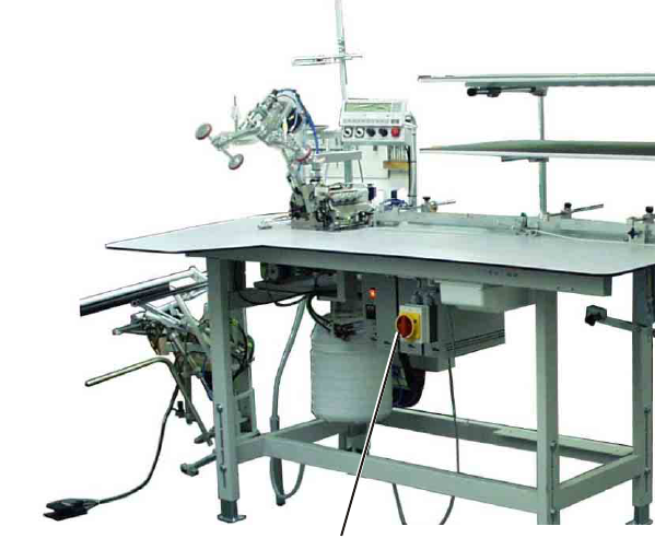
External control panel Efka V850 with:
- Menu navigation
- Freely programmable parameters for
“Differential bottom feed (optional)”, “Needle feed
(optional)”, “Ejector roller”, “Puller”, “Machine parameters”,
“Global parameters”, “Program sequences”
- Input and output tests
- Check routine for step motors
- 20 program storage locations
- up to 7 seam programs per program storage location
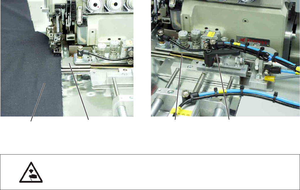
Vertical cutter with suction for overlocking and serging in one
operation
Chain separator with suction, programmable
Adjustable blowing nozzles in the table top for supporting the
material feed, mechanical regulation of the blowing intensity by an
adjusting knob, duration of table blowing programmable
Preparation table with mouse and reverse device for the
workpieces; for a uniform material guide and higher productivity
Special sewing equipment for trousers side seams with side seam
pockets and wing pockets
Narrow sewing tools incl. narrow sewing foot for trouble-free
guiding / sewing of the pocket openings
Automatic contour modulation by programmable puller
Height-adjustable stand, infinitely variable from 850 mm to
1200 mm
Automatic fullness distribution by step motor-controlled needle and
bottom feed (optional). Within a seam program the fullness of the
needle and bottom feed can be programmed at the control panel
via 3 freely selectable lines. User-friendly adjusting possibility of
the fullness in one line via each one controller.
Integrated stacking device
Manual stacking via shortcut key
1.3 Technical data:
Machine head: Pegasus EXT 3216-03/233-K 5x5-KH-021A
Stitch type: 401, 515, 516
Number of needles: 1 or 2
Needle system: B27
Needle size: Nm 80 to Nm 110
Hook type: Chainstitch hook, cross-line, overlock hook
Threads: see table chapter 4.2
Speed: 6500 r/ min
Speed upon
delivery: 6500 r/ min
Stitch length min. : 0.5 mm
max.: 3.5 mm
Seam width: 10 mm
Optional: 8 - 12 mm
Material: Light to medium-weight material
Operating pressure: 6 bar
Air consumption: 20 NL per working cycle
Rated voltage: 1 x 230 V 50/60 Hz
Rated load: 1.00 kVA
4
Dimensions: 2300 x 1300 x 1500 mm (L x W x H)
Working height: 850...1200 mm
(upper table top edge)
Weight: 125 kg
Noise level: LC = 81dB (A)
Workstation-specific emission value according to DIN 45635-48-B-1
Stitch length: 2.6 mm
Seam length: 1000 mm
Speed: 6500 r/min
Material G1 DIN 23328: 2 layers
Measuring point according to
DIN 4895 Part 1 X = 550 mm Y = 350 mm Z = 600 mm
x - axis = at right angles to the feeding direction
y - axis = main feeding direction
z - axis = height
2. Optional equipment
See annex
5
1
6
3. Switching on - Switching off - Program stop
3.1 Switching on
Switch on main switch 1 (turn in clockwise direction).
The control loads the machine program.
The basic display appears in the display of the control panel.
3.2 Switching off
Switch off main switch 1 (turn counter-clockwise).
1
3.3 Program stop
For an immediate stop in case of operating errors, needle breakage
etc. the safety system of the 1281/5 provides the following measures:
Press program stop switch 2 at the control panel.
The running operations are stopped immediately.
Turn main switch 1 counter-clockwise.
The sewing unit drops out immediately;
all movements of the sewing unit stop immediately.
3.4 Restart after program stop
Caution: Risk of injury!
Switch the main switch off.
Clear the fault only with the sewing unit switched off.
Only restart the sewing unit after the fault has been cleared.
Switch on main switch 1 (turn in clockwise direction).
Unlock the program stop switch.
The control loads the machine program.
The basic display appears in the display of the control panel.
The sewing unit is ready for operation again.
7
1
2 1
2
4. Operation of the sewing machine head
4.1 General notes
The operation of the sewing machine head (needle insertion, threading
of needle thread and hook thread etc.) is described in the attached
separate Pegasus operating instructions.
The instruction manual is included in the accessories of the sewing
unit.
Attention: Risk of injury!
Please read the operating instructions of the sewing machine head
carefully and observe all notes on safety.
8
4.2 Recommended threads
Needle system: B27
Recommended
needle size: Nm 80 for very thin material
Nm 90 for thin material
Nm 100 for medium-weight material
High sewing security and good sewability are achieved with the
following core threads:
Two-ply polyester endless polyester core-spun
(e.g. Epic Poly-Poly, Rasant x, Saba C, ...)
Two-ply polyester endless cotton core-spun
(e.g. Frikka, Koban, Rasant, ...)
If these threads are not available, the polyester fibre or cotton threads
listed in the table can also be sewn.
Often two-ply core threads are offered by the thread manufacturers
with the same designation as three-ply polyester fibre threads
(3cyl.-spun).This causes uncertainty with regard to twisting and thread
thickness.
When in doubt, unravel the thread and check whether it is twisted 2- or
3-ply.
The label no. 120 on the thread reel of a core thread corresponds e.g.
to the thread size Nm 80/2 (see table values in brackets).
In case of monofilament threads you can use needle threads and hook
threads of the same thickness. The best results are achieved with soft
and elastic threads (software) of the thread thickness 130 Denier.
Recommended thread thicknesses:
Needle size Core thread Core thread
Nm
Needle thread Hook thread Needle thread Hook thread
Polyester Polyester Polyester Cotton
endless core-spun endless core-spun
Label No. Label No. Label No. Label No.
80
90 120 (Nm 80/2) 120 (Nm 80/2) 120 (Nm 80/2) 120 (Nm 80/2)
100 100 (Nm 65/2) 100 (Nm 65/2) 100 (Nm 65/2) 100 (Nm 65/2)
Needle size Polyester fibre thread Cotton thread
Nm (3cyl.-spun)
Needle thread Hook thread Needle thread Hook thread
80 Nm 120/3 Nm 120/3 Ne
B
60/3-80/3 Ne
B
60/3-80/3
90 Nm 80/3-120/3 Nm 80/3-120/3 Ne
B
50/3-70/3 Ne
B
50/3-70/3
100 Nm 70/3-100/3 Nm 70/3-100/3 Ne
B
40/3-60/3 Ne
B
40/3-60/3
1
9
4.3 Removing / Putting on the fabric sliding sheet
The fabric sliding sheet 2 is held in the gap of the table top by the
magnets 1.
The edge guide 3 is fastened on the fabric sliding sheet.
Removing the fabric sliding sheet
Carefully remove the edge guide 3 from the magnets in upward
direction.
Swivel the fabric sliding sheet aside.
The lower section of the sewing machine head is accessible now.
Putting on the fabric sliding sheet
Push the fabric sliding sheet into the gap of the table top and insert
in downward direction.
10
2 1
2 3
5. Operation of the sewing unit
5.1 Preparation table and worktable
The sewing unit is equipped with two preparation tables 1 and 2. The
skirt parts or trousers parts are positioned on them.
On the worktable 4 the trousers parts or skirt parts are fed and
clamped with the mouse 3.
11
1
2 1
4 3
5.2 Mouse with guide rail and return mechanism
The mouse is used for clamping the trousers and skirt parts to avoid
their sliding away.
The guide rail 3 is flexible and adaptable to the contour of the
workpiece.
Caution: Risk of injury !
Do not reach into the open mouse.
Inserting the workpiece
Place the workpiece between mouse plate 2 and clamping arm 1.
Close the mouse.
During the sewing process the mouse is drawn along the guide rail 3
until the opening of the clamping arm 1 is released by a limit switch.
Then the mouse is pulled back by the return mechanism 4 until the
adjustable stop 5 is touched.
12
3 2 1
7 6 5 4
Aligning the guide rail 3
Place the workpiece 8 on the worktable opposite to the sewing
direction.
Loosen toggle screws 9.
Place the guide rail 3 close to the contour of the workpiece.
Tighten toggle screws 9 again.
Opening the mouse manually
#
Actuate lever 10. The mouse opens.
13
1
9 8
9 3
10
5.3 Feeding the workpieces and starting the sewing process
The sewing unit for closing seams 1281/5 works semi-automatically at
high speed.
The operator of the sewing unit has to do the following:
® call up the desired seam program;
® feed and align the workpiece precisely;
® sew the first seam section manually;
® start the automatic sewing process;
® supervise the sewing process of the unit;
® remove the finished parts from the stacker.
Feeding the workpieces and starting the sewing process
1) Select the seam program at the control panel.
2) Place the workpieces 2 on the worktable and align them.
3) Position the workpieces in the mouse 1.
4) Close the mouse.
5) Push both workpieces under the sewing foot 6 and directly in front
of the needle.
6) Step the foot pedal forward and sew over the pocket and the hip
bow manually.
7) Separate the trousers or skirt parts with three fingers. Hold one
finger under, one between and one above the workpieces.
8) Step the foot switch back. The contour guide moves between the
parts. The feeding puller lowers.
9) Step the foot pedal forward. The automatic sewing process starts.
10) The finished workpieces are stacked.
11) The mouse returns to the feeding position.
14
2 1
6 5 4 3
5.4 Adjusting the blowing air for the nozzles in the table top
The blowing nozzles 1 in the table top support the precise stacking of
the workpieces.
Set the intensity of the air blast by dial 2 at the control panel.
Turn the dial to the right = increase the intensity of air blast
Turn the dial to the left = reduce the intensity of air blast
1
15
2
1
5.5 Setting the return speed of the mouse
The cylinder 2 presses the mouse mechanics 1 down. Thus, the mouse
is pulled back to the feeding position.
The return speed can be set.
Set the speed by dial 3 at the control panel.
Turn dial to the right = higher speed
Turn dial to the left = less speed
16
3
2 1
5.6 Adjusting the fullness of needle and bottom feed
Operator terminal in case of fullness adjustment Operator terminal in case of fullness
adjustment via step motors
via cylinder (optional equipment)
Needle feed, bottom feed and puller feed can be adapted to the sewing
conditions with the dials 1 and 2.
Via the control parameters you can determine which feed is changed
with the dial 2.
Adjusting the puller feed
Set the dial 1 correspondingly.
Setting range: + 0 to 6 right
- 0 to 6 left
Adjusting the needle and bottom feed
Make the corresponding settings in the control in the menu
“Seam-specific parameters”.
Set the dial 2 correspondingly.
Setting range: + 0 to 6 right
- 0 to 6 left
17
1
1
2 1
5.7 Setting the pressure of the puller
The pressure of the puller rollers 1 can be influenced via turning
knob 2.
Turn knob 2 to the right.
The pressure is increased.
Turn knob 2 to the left.
The pressure is reduced.
18
2
1
5.8 Stacker
The finished workpieces are stacked on the throw-over stacker 2.
The stacked and clamped workpieces can be removed by actuating the
foot switch 1.
The stacker is accessed by a control pulse. The pneumatic functions
can be taken from the pneumatic wiring diagram.
Caution: Risk of injury!
Do not reach into the working area of the throw-over stacker during the
stacking operation.
Manual stacking
Press key 3 at the control panel.
A stacking process is carried out.
Removing stacked parts
Actuate foot switch 1 and keep it actuated.
Remove the stacked parts.
19
1
3
2 1
6. Operation of the control
6.1 Operator terminal
For the input and output of data an operator terminal with an LCD
display and function keys is used.
Display Enter keys
Keys 1 - 0 Function keys
Potentiometer Program stop
Key Function
Seam program 1 to program 99
Sewing stop within the seam
Move the contour guide back to the basic position
Manual stacking
Menu selection/ Store data
Needle feed, seam lines and quantities adjustable
Differential feed, seam lines and quantities adjustable
Adjust the ejector roller
Adjust the puller
Set the machine parameters
Switch the potentiometer on / off in the individual lines
(optional equipment)
Adjust seam line
Input-/ Output test
20
Key Function
Program the sequence (S)
Creation of programs (Prg)
Setting the global parameters
Enter key
Select parameter / scroll
Alter parameter values
21
1
6.2 User interface
6.2.1 Menu structure of the sewing and setting programs
Switch on
main switch
Main screen
to
Call up sewing programs Menu selection 7 F1 F2
sewing stop Mouse back Manual
within the to basic stacking
seam position
Key 1 Set needle feed via potentiometer
Key 2 Set bottom feed via potentiometer
Key 3 Set puller feed via potentiometer
Key 4 Adjust the puller
Key 5 Set machine parameters
Key 6 Switch the potentiometer on / off (optional equipment)
Key 7 Set seam line
22
Key 8 Input- Output test
Key 9 Set global parameters
Key 0 Creation of programs / Creation of sequences
Calling up sewing programs
Switch the main switch on.
The control initializes.
The seam program previously used is loaded.
Press one of the keys “1, 2, 3, 4, 5, 6, 7, 8, 9, 0”.
The selected seam program is loaded.
Calling up the parameter menu
Switch the main switch on.
The control initializes.
The previously used program appears in the display.
Press key “P”.
The selection menu is called up.
Press one of the keys “1, 2, 3, 4, 5, 6, 7, 8, 9, 0”.
The display changes over to the corresponding function.
Mouse back
When the seam program is selected:
Press key “F1”.
The mouse returns to its basic position.
Manual stacking
When the seam program is selected:
Press key “F2”.
The stacker makes a stacking movement.
23
1
6.3 Seam programs
Designation of the individual seams:
4 = Crotch seam of hind trousers on top/ lining down
6 = Crotch seam of hind trousers down/ lining on top
5 = Side seam of hind trousers down/ lining on top
7 = Side seam of hind trousers on top/ lining down
A seam program in the display of the control panel
Program No. Seam No.
24
4
6
5
The sewing unit 1281/5 is delivered with 9 standard seam programs:
Program Seam Operation Position of Notes
No. No. trousers
1 4 Close crotch seam Hind trousers on top Automatical sewing with
Lining down contour guide
2 6 Close crotch seam Hind trousers down Automatical sewing with
Lining on top contour guide
3 4 Close crotch seam
6 Close crotch seam Alternate sewing
4 7 Close side seam Hind trousers on top Manual sewing and guiding
Lining down in the hip bow area
afterwards automatical
sewing
5 5 Close side seam Hind trousers down Close side seam manual
Lining on top sewing and guiding
afterwards automatical sewing
6 7 Close side seam
5 Close side seam Alternate sewing
7 5 Close side seam Hind trousers down Automatical sewing with
Lining on top contour guide
8 7 Close side seam Hind trousers on top Automatical sewing with
Lining down contour guide
9 5 Close side seam
7 Close side seam Alternate sewing
25
1
4
6
5
6.4 Adjusting the control
The parameter values are altered in the individual parameter menus.
Press key “P”.
Select the menu item.
Select the parameter to be altered with the keys “F1” or “F2”.
Press key “E”.
Alter the parameter value with the keys “Plus” or “Minus”.
Press key “P”.
The new parameter value is stored.
Press key “P”.
You return to the selection menu.
Press key “P”.
You return to the sewing program.
Fullness distribution with needle and bottom feed
According to the equipment of the sewing station the parameters for
the needle and bottom feed are occupied differently.
The sketches below show the individual lines.
With cylinder
Line 1 Line 2 Line 3 Basic seam
Stitches Stitches Stitches
With step motor
Line 1 Line 2 Line 3 Basic seam
Stitches Stitches Stitches
26
6.4.1 Altering seam-specific parameters
Needle feed (with cylinder)
Via this parameter the needle feed is set.
Parameter 01: Line 1
Number of stitches until the needle feed engages
Setting range: 0 - 2000
Parameter 02: Fullness line 1 ON/ OFF
Setting range: 0 / 1
Parameter 03: Line 2
Number of stitches how long the needle feed is
engaged
Setting range: 0 - 2000
Parameter 04: Fullness line 2 ON/ OFF
Setting range: 0/1
Parameter 05: Line 3
Number of stitches how long the needle feed is
engaged
Setting range: 0 - 2000
Parameter 06: Fullness line 3 ON/ OFF
Setting range: 0/1
Needle feed (with step motor)
Via this parameter the needle feed with step motor drive is set.
Parameter 01: Line 1
Number of stitches
Setting range: 0 - 2000
Parameter 02: Fullness in line 1
Setting range: 0 - 2000
Parameter 03: Line 2
Number of stitches
Setting range: 0 - 2000
Parameter 04: Fullness in line 2
Setting range: 0 - 2000
Parameter 05: Line 3
Number of stitches
Setting range: 0 - 2000
Parameter 06: Fullness in line 3
Setting range: 0 - 2000
27
1
Bottom feed (with cylinder)
Via this parameter the differential feed is set.
Parameter 07: Line 1
Number of stitches until the differential bottom feed
engages
Setting range: 0 - 2000
Parameter 08: Fullness line 1 ON/ OFF
Setting range: 0 / 1
Parameter 09: Line 2
Number of stitches how long the differential bottom
feed is engaged
Setting range: 0 - 2000
Parameter 10: Fullness line 2 ON/ OFF
Setting range: 0 / 1
Parameter 11: Line 3
Number of stitches how long the differential bottom
feed is engaged
Setting range: 0 - 2000
Parameter 12: Fullness line 2 ON/ OFF
Setting range: 0 / 1
Bottom feed (with step motor)
Via this parameter the differential feed with step motor drive is set.
Parameter 07: Line 1
Number of stitches
Setting range: 0 - 2000
Parameter 08: Fullness in line 1
Setting range: 0 - 2000
Parameter 09: Line 2
Number of stitches
Setting range: 0 - 2000
Parameter 10: Fullness in line 2
Setting range: 0 - 2000
Parameter 11: Line 3
Number of stitches
Setting range: 0 - 2000
Parameter 12: Fullness in line 3
Setting range: 0 - 2000
28
Setting the ejector roller
Via this parameter the ejector roller is set.
Parameter 16: Number of stitches how long the seam chain
is sucked (seam beginning)
Setting range: 0....120
Parameter 17: Switch the stacker on or off
Setting range: 0 / 1
Parameter 20: Number of stitches when the ejector roller lowers
Setting range: 0 …400 stitches
Parameter 21: Number of stitches how long the ejector roller is
switched on
Setting range: 0 …400 stitches
Parameter 22: Number of stitches after “light barrier bright”, until
the ejector roller stops
Setting range: 0 …30 stitches
Parameter 23: Time how long the ejector roller is active
Setting range: 0 …1000
Parameter 47: Time of the stacker movement
Input: 0 …2000
Parameter 53: Time when the ejector roller lifts
Setting range: 0 …2000
Setting the puller
Via this parameter the puller is set.
Parameter 26: Number of stitches when the puller lowers
Setting range: 0 …400 stitches
Parameter 27: Number of stitches how long the puller remains
lowered
Setting range: 0 …400 stitches
Parameter 51: Puller speed
lower value = increased puller speed
higher value = lower puller speed
Setting range: 400 … 1000
Parameter 100: Number of stitches how long the puller lifts
Setting range: 0...400 stitches
29
1
Altering the machine parameters
Parameter 30: Set the main speed
Setting range: 0 - 6500
Parameter 31: Manual sewing on/ off
Setting range: 0 / 1
Parameter 32: Number of stitches how long the table blowing
remains switched on
Setting range: 0 …400 stitches
Parameter 33: Number of stitches until the automatic start engages
after the sewing start
Setting range: 0 ...
Parameter 34: Number of stitches until the contour guide lowers
Setting range: 0 …400 stitches
Parameter 35: Number of stitches until the contour guide retracts
laterally
Setting range: 0 …400 stitches
Parameter 36: Number of stitches until the feeding unit lowers
Setting range: 0 ...400
Parameter 37: Start mode contour modulation
1 = front, left
2 = rear, right
3 = rear, left
Setting range: Modes 1, 2, 3
Parameter 60: Soft start speed
Setting range: 500 ...5000
Parameter 61: Switch the soft start on or off
Setting range: 0 / 1
Parameter 76: Switch the start on or off via light barrier
Setting range: 0 / 1
Parameter 77: Switch the autostart on or off
Setting range: 0 / 1
Parameter 78: Number of stitches until the autostart starts
Setting range: 0 ...400 stitches
30
Altering the potentiometer
Parameter 18: Needle feed potentiometer Off / On
Setting range: 0 / 1
Parameter 19: Differential feed potentiometer Off / On
Setting range: 0 / 1
Parameter 24: Line 1,
Needle feed potentiometer Off / On
Setting range: 0 / 1
Parameter 25: Line 2,
Needle feed potentiometer Off / On
Setting range: 0 / 1
Parameter 28: Line 3,
Needle feed potentiometer Off / On
Setting range: 0 / 1
Parameter 96: Line 1,
Differential feed potentiometer Off / On
Setting range: 0 / 1
Parameter 97: Line 2,
Differential feed potentiometer Off / On
Setting range: 0 / 1
Parameter 99: Line 3,
Differential feed potentiometer Off / On
Setting range: 0 / 1
31
1
Setting the seam line
Parameter 81: Length of line 1
Setting range: 0 ...
Parameter 82: Line 1
Reduced speed Off / On
Setting range: 0 / 1
Parameter 83: Line 1
Reduced speed
Setting range: 500...6500
Parameter 84: Line 1
Stop at the end of the line Off / On
Setting range: 0 / 1
Parameter 85: Line 1
Sewing foot lift at the end of the line Off / On
Setting range: 0 / 1
Parameter 86: Length of line 2
Setting range: 0 ...
Parameter 87: Line 2
Reduced speed Off / On
Setting range: 0 / 1
Parameter 88: Line 2
Reduced speed
Setting range: 500...6500
Parameter 89: Line 2
Stop at the end of the line Off / On
Setting range: 0 / 1
Parameter 91: Length of line 3
Setting range: 0 ...
Parameter 92: Line 3
Reduced speed Off / On
Setting range: 0 / 1
Parameter 93: Line 3
Reduced speed
Setting range: 500...6500
Parameter 94: Line 3
Stop at the end of the line Off / On
Setting range: 0 / 1
32
6.4.2 Altering global parameters
Parameter 29: Needle feed
Maximum run
Input: 0 …120
Parameter 38: Start delay light barrier
Input: 0 …2000
Parameter 39: Differential feed
Maximum run
Input: 0 …120
Parameter 40: Basic value needle feed
Input: 0 …120
Parameter 41: Basic value needle feed on / off
Input: 0 / 1
Parameter 42: Basic value differential bottom feed
Input: 0 …120
Parameter 43: Basic value differential bottom feed on/ off
Input: 0 / 1
Parameter 45: Number of stitches until the table blowing is
switched on
Input: 0 …400
Parameter 46: Duration of the stacker impulse
Input: 0 ...2000
Parameter 47: Time of the stacker movement
Input: 0 …2000
Parameter 48: Speed limitation
Input: max. 6500
Parameter 49: Speed during the warp separation
Input: 500...5000
Parameter 50: Number of stitches until the thread tension is opened
(seam end)
Input: 0....50
Parameter 52: Speed ejector roller
Input: 500 … 1200
Parameter 54: Duration of impulse “mouse back”
Input: 500 … 4000
Parameter 55: Time until the feeding unit lifts after the ejector roller
Input: 0....2000
Parameter 56: Seam programming on/ off
On = 1 Determine the seam sequences in the
current program
. Off = 0
Create the next free program with seams
Input: 0 / 1
Parameter 80: Reset the daily piece counter.
33
1
Altering global parameters
Parameter 58: Display of the software version
Parameter 59: Number of stitches how long the seam chain is
sucked (seam beginning)
Input: 0 …50
Parameter 65: Thread tension lift
Input: 0 …50
Parameter 79: Soft start after “Stop in the seam”
Input: 0 …500
6.4.3 Input - Output test
Via the input - output test the different input and output elements can
be checked.
Input test
Press key “P”.
Press key “8”.
Actuate the corresponding input.
Example:
Cover the light barrier.
Press key “Program stop”.
The program is quitted.
Input elements
Switch Designation
01 Light barrier 01 start
05 Switch “Program stop”
06 Mouse back
11 Potentiometer needle feed and differential bottom feed
(optional equipment)
12 Potentiometer puller (optional equipment)
34
Output test
Press key “P”.
Press key “8”.
Press key “Plus”.
Select the output element to be tested with the keys “Plus” or
Minus”.
Switch the output on or off with the key “F2”.
Press key “Program stop”.
The program is quitted.
Output elements
Switch Designation
Y01 Sewing foot up / down
Y02 Thread tension lift open
Y03 Contour guide up / down
Y04 Stacker off / on
Y05 Ejector roller up / down
Y06 Feeding unit up / down
Y07 Contour guide forward / backward
Y08 Contour guide blowing on
Y09 Move contour guide laterally
Y10 Differential bottom feed on / off
Y11 Needle feed on / off
Y12 Warp separator off / on
Y13 Table blowing off / on
Y14 Dirt suction off / on
Y15 Puller up / down
Y16 Mouse back
35
1
6.4.4 Creation of seam programs
Note
Before a new seam program can be created or an existing one can be
deleted, the global parameter “56” has to be set to the value “0”.
This avoids that the existing programs are changed inadvertently.
Press key “P”.
Press key “0” (global parameters).
Change over to parameter 56 with key “F1”.
Press key “E”.
The parameter 56 is selected.
Set the parameter value to “0" with key “Minus.
Press key “P”.
The new parameter value is stored.
Press key “P”.
You return to the selection menu.
Creating a seam program
Press key “P”.
Press key “9” (Prg = programs).
Press key “F1” twice.
Select a seam with one of the keys “1” to “9”.
Press key “E”.
The selected seam is taken over.
Select a further seam with one of the keys “1” to “9”.
or
Press key “P”.
The new setting is stored and you return to the selection menu.
Note
After the creation of a new seam program the parameter “56" has to be
reset to the value “1” for safety reasons.
36
1
6.4.5 Deleting a seam program
Press key “P
Press key “9
Press key “F2”.
The display indicates:
DELETE?
Press key “F2” anew.
The program is deleted.
Press key “P”.
You return to the selection menu.
6.4.6 Altering seam programs (Changing / Completing the sequence)
Note
Before a seam program can be altered,the parameter “56” has to be
set to the value “1".
This avoids that the existing programs are deleted inadvertently. (see
chapter 6.4.3, paragraph 1)
Select the program to be altered.
Press key “P”.
Press key “9” (S = sequence).
Select a free location with the keys “Plus” or “Minus”.
Select a seam number with the keys “1” to “9”.
You can select further seam numbers or quit the menu.
Select another free location with the keys “Plus” or “Minus”.
Or
Press key “P”.
The seam program is stored and you return to the selection menu.
Press key “P”.
You return to the selection menu.
37
7. Error messages
In case of an error in the control system or in the machine program
corresponding error messages are indicated in the display.
Display Meaning
Error 1 One of the parameters “18” or “19” is switched on
(value = 1)
Error 2 Both parameters “18” and “19” are switched on
(value = 1)
Error 3 In the current program the last
existing seam was to be deleted.
Errors of free programming
Info U1 FP custom code wrong, e.g. describing a parameter
which does not exist.
Info U2 Wrong system function
Info U3 Wrong in / out number
Info U4 Too many user variables
Info U5 Too many system variables
Info U6 Not enough storage location for the user program
Info U7 Wrong or undefined key in the Vario
Info U8 Unknown device address
Info U9 Fatal exception error
Errors and informations bootload
Info B1 Switch on control in the boot mode and press key “F2”
Info B2 Programming of segment number
Info B3 Flash programming failed
Info B4 Flash programming okay
38
8. USB stick
8.1 General notes
The USB stick 1 serves for storing and transferring of the sewing unit
software.
By means of the USB stick program and parameter data can also be
transferred to other sewing units.
Commercially available USB 1 sticks can be used, too.
8.2 Formatting the USB stick
Before using a new USB stick this has to be formatted correspondingly.
The file format is the “FAT 16” system.
Format the USB stick with the FAT 16 system via a PC.
8.3 Plugging the USB stick in the control
Switch the main switch off.
Plug the USB stick 1 in the lower slot of the Efka control.
Press key “P” and keep it pressed.
Switch the main switch on.
The message appears for a moment.
USB. DEV. DETECT:
Keep key “P” pressed until the following message appears in the
display:
SERVICE - CODE
Enter CODE 3112.
Press key “E”.
39
1
1
8.4 USB functions
The following functions can be carried out with a USB stick:
1) Storing and loading of global parameters
File extension = *. PAR
Parameter Function
F-510 Securing from the control on the USB stick
F-511 Loading from the USB stick in the control
F-512 Comparing USB stick and control data
F-513 Deleting data from the USB stick
2) Storing and loading of programs and seam parameters
File extension = *.PAY
Parameter Function
F-514 Securing from the control on the USB stick
F-515 Loading from the USB stick in the control
F-516 Comparing USB stick and control data
F-517 Deleting data from the USB stick
3) Loading a new software version
File extension = *.PRG
Parameter Function
F-523 Load a new software version from the USB
stick in the
control
By means of the FAT 16 file system the control allocates file names
with max. 8 characters.
Max. 8 characters 1 2 3 4 5 6 7 8
Software version 1 2 2 0 _ 5 D _ 1 A .PRG
Machine type
Language
Equipment
1 = Parameter file
2 = Program file
Version
40
If different program or parameter files are stored, the control allocates
a new name each.
Example:
Storing of different parameter data
1st file 0100DATA.PAR
2nd file 0101DATA.PAR
etc.
The files can individually be renamed by the file manager or explorer
on a PC.
Note
On principle, the Efka control can read data from the main level of the
USB stick only. Data from subdirectories cannot be processed.
41
1
8.4.1 Storing data on the USB stick
Enter parameter.
Example: 510
Press key “E
The cursor flashes.
Press key “F2”.
The file name chosen by the control appears.
Example
0100DATA.PAR
Press key “E”.
The data are written on the USB stick.
Note
The file name is allocated automatically.
8.4.2 Loading data from the USB stick
Enter parameter.
Example: 511
Press key “E
The cursor flashes.
Press key “F2”.
The name of the first file stored on the stick appears.
Example
0100DATA.PAR
Select the desired file with the keys “+” or “-”.
Press key “E”.
The message appears.
READ DATA YES = E
Press key “E” within 2 seconds.
The data are read from the USB stick.
42
8.4.3 Data comparison
Enter parameter.
Example: 512
Press key “E”.
The file name chosen by the control appears.
Example
0100DATA.PAR
Press key “E”.
The message appears.
READ DATA YES = E
Press key “E” within 2 seconds.
The data of the USB stick and the control are compared.
The message appears.
READ DATA
Possible displays
DATA OK The data on the stick are identical
with the data of the control
DATA DIFFERENT The data of the stick and the control are
not identical.
8.4.4 Deleting data from the USB stick
Enter parameter.
Example: 513
Press key “E”.
The cursor flashes.
Press key “F2”.
The name of the first file appears on the stick.
Example
0100DATA.PAR
Select the desired file with the keys “+” or “-”.
Example
0105DATA.PAR
Press key “E” within 2 seconds.
The data from the USB stick are deleted.
The message appears.
READY
43
1
8.4.5 Loading software version from the USB stick
Enter parameter 523.
Press key “E”.
The cursor flashes.
Press key “F2”.
The name of the first file stored on the stick appears.
Example
20_5D_1A.PRG
Select the desired parameter file with the keys “+” or “-”.
Press key “E”.
The message appears.
READ DATA YES = E
Press key “E” within 2 seconds.
The data are read from the USB stick.
Press key “P” and wait approx. 3 seconds until “Save Data” fades
out.
Press key “E” twice.
The cursor flashes.
Press key “F2”.
The name of the first file stored on the stick appears.
Example
20_5D_2A.PRG
Select the desired program file with the keys “+” or “-”.
Press key “E”.
The message appears.
READ DATA YES = E
Press key “E” within 2 seconds.
The data are read from the USB stick.
Switch the main switch off and on again.
The new software version is loaded now.
44
8.5 Removing the USB stick
Switch the main switch off.
Pull the USB stick 1 out of the slot of the Efka control.
45
1
1
9. Maintenance
9.1 Cleaning and checking
Caution: Risk of injury !
Switch the main switch off.
The maintenance of the engineered sewing station must only be
carried out with the machine switched off.
Maintenance work has to be done after the intervals indicated in the
tables at the latest (see column “Operating hours”).
The processing of fluffy material may require shorter maintenance
intervals.
A clean sewing station protects from disturbances.
46
2
1
6 5 4 3
Maintenance work Explanation Operating
to be done hours
Machine head
- Remove sewing dust and thread
remainders.
(e.g. with compressed air pistol)
Clean the entire area 1 of the thread guides
under the fabric sliding sheet
8
Suction device
Empty container 2 of the suction device
- Turn the bottom part of the container to the
left
and remove it
- Empty the container
- Screw the bottom part on again in
clockwise direction
8
Pneumatic system
- Check the water level in the
pressure regulator 3
- Clean the filter insert 4
- Make leak test of the system
The water level must not rise up to the filter
insert 4.
- Let the water run out of the water separator
under pressure after pressing the drain plug 5.
The filter insert 4 separates dirt and condensed
water.
- Separate the sewing unit from the
compressed air net.
- Push in drain plug 5.
The pneumatic system of the
sewing unit has to be pressureless.
- Screw the water separator 6 off
- Remove filter insert 4.
Wash the dirty filter tray and the filter insert
with benzine (no solvent!)
and blow them clean.
- Reassemble the water separator
and connect the maintenance unit.
40
500
500
47
1
9.2 Oil lubrication
Caution: Risk of injury !
Oil may cause skin eruption.
Avoid a longer contact with the skin.
Wash yourself thoroughly after a contact.
ATTENTION !
The handling and disposal of mineral oils is subject to legal
regulations.
Deliver used oil to an authorized collecting station.
Conserve your environment.
Be careful not to spill any oil.
Oil the head of the sewing unit exclusively with lubricating oil DA-10 or
an equivalent oil with the following specification:
Viscosity at 40° C: 10 mm²/s
Ignition point: 150° C
DA-10 can be bought at the sales points of DÜRKOPP ADLER AG
under the following parts numbers:
Container 250 ml: 9047 000011
Container 1 litre: 9047 000012
Container 2 litres: 9047 000013
Container 5 litres: 9047 000014
Maintenance work Explanation Operating
to be done hours
Lubrication
Check the oil level at the sewing machine
head regularly (inspection glass 1 and 2).
Please take further details from the
enclosed operating instructions of the
sewing machine head.
8
48
1
In dex Page:
Part 2: Assembly in structions cl. 1281/5
1. Sco pe of de li very.............................................. 3
2. Ge ne ral no tes ................................................ 3
3. In stal ling the se wing unit ........................................ 4
3.1 Trans port pro tec tions ............................................ 4
3.2 Setting the wor king height ......................................... 5
3.3 Mounting the thread reel hol der...................................... 6
3.4 Moun ting the ma te ri al rests ........................................ 6
4. Elec tri cal con nec ti on ........................................... 7
4.1 Che cking the no mi nal vol ta ge....................................... 7
4.2 Ma king the mains con nec ti on....................................... 7
5. Pneu ma tic con nec ti on .......................................... 8
6. Put ting into ope ra ti on .......................................... 9
6.1 Se wing test .................................................. 9
2
1
7
8
4
2
5
6
3
9
2
1. Sco pe of de li very
The scope of delivery depends on your order.
The sewing unit consists of:
1 Sewing machine head (as per order)
2 Thread reel holder
3 Control with control panel
4 Material rests
5 Stand and table top
6 Foot pedal
7 Suction unit with suction container
8 Stacker
9 Feeding unit with puller
Compressed air maintenance unit with compressed air
pistol
2. Ge ne ral no tes
ATTENTION !
The sewing unit must only be installed by trained specialist staff.
Any work on the electrical equipment of the sewing unit must only be
carried out by electricians or correspondingly instructed persons.
The mains plug must be pulled out.
The enclosed operating instructions of the drive motor manufacturer
have to be observed.
3
3. In stal ling the se wing unit
3.1 Trans port pro tec tions
Before the installation of the sewing unit all transport protections have
to be removed.
Remove the security tapes at the thread reel holder, machine table
etc.
Remove the protective foils 1.
Remove the security tapes 2 from the stacker.
Remove the protections from the mouse 4 and the reverse
device 3.
4
1
2
4
3
3.2 Setting the working height
The working height is adjustable between 850 and 1200 mm
(measured up to the top edge of the table top).
Loosen screws 1 at the spars.
Set the desired working height with the help of suitable auxiliary
means.
In order to avoid jamming lift the table top equally on both sides.
Retighten screws 1 at the spars.
5
2
1
1
6
3.3 Mounting the thre ad reel hol der
Insert thread reel holder 1 in retainer 2.
Tighten the thread reel holder with the two screws 3.
3.4 Moun ting the ma te ri al rests
The material rests have be demounted for transportation.
Loosen the screws 2 at the fixtures 3.
Insert the bars 1 in the fixtures 3.
Retighten the screws 2 at the fixtures 3.
Loosen the screws at the fixtures 4 and 5 and align the height of
the material rests.
Retighten the screws at the fixtures 4 and 5.
3 2 1
3 2 1
3 1 5 4 3 1
4. Elec tri cal con nec ti on
ATTENTION !
Any work on the electrical equipment of the sewing unit must only be
carried out by electricians or correspondingly instructed persons.
The mains plug must be pulled out.
4.1 Che cking the no mi nal vol ta ge
ATTENTION !
The nominal voltage indicated on the type plate of the sewing machine
control and the mains voltage must correspond.
Nominal voltage = 190 - 240 V, 50/60 Hz
4.2 Ma king the mains con nec ti on
Connect the mains plug.
7
2
5. Pneu ma tic con nec ti on
For the operation of the pneumatic components the sewing unit has to
be provided with anhydrous compressed air.
ATTENTION!
For a trouble-free function of the pneumatic control processes the
compressed air net has to be rated as follows:
Even in the moment of maximum air consumption the minimum
operating pressure must not drop below 6 bar.
In case of a too high air pressure decrease:
Increase the compressor output.
Increase the diameter of the compressed air supply line.
Connecting the compressed air maintenance unit
Connect the connecting hose 3 to the compressed air net.
Setting the operating pressure
The operating pressure amounts to 6 bar.
It can be read off at the manometer 1.
For setting the operating pressure pull up and turn the rotary
handle 2.
- Turn in clockwise direction = increase the pressure
- Turn counter-clockwise = reduce the pressure
ATTENTION !
No oil-bearing compressed air must be fed from the compressed air
net.
Behind the filter cleaned compressed air is withdrawn as blowing air
for cleaning machine parts and for blowing workpieces out.
Oil particles contained in the blowing air lead to malfunction and stains
on the workpieces.
8
3 2 1
6. Put ting into ope ra ti on
6.1 Se wing test
After completion of the installation work a sewing test should be made.
Plug in the mains plug.
Caution: Risk of injury!
Switch the main switch off.
Thread in needle and hook thread only with the sewing unit switched
off.
Thread in needle and hook thread
(see operating instructions of the sewing machine head).
Switch the main switch on.
The control is initialized.
Select the sewing program.
For feeding and operating see part 1:
Operating instructions 1281/5
2
9
Für Ihre No tizen:
10
Index Page:
Part 3: Service instructions class 1281/5
1. General notes ................................................ 3
2. Brief instructions for the sewing head
2.1 Adjusting the height of the needle bar .................................. 4
2.2 Adjusting the hook .............................................. 5
2.2.1 Distance between left hook and needle.................................. 5
2.2.2 Distance between right hook and needlel ................................ 7
2.3 Adjusting the needle protection ...................................... 9
2.3.1 Hind needle protection............................................ 9
2.3.2 Front needle protection ........................................... 10
2.4 Adjusting the feed-dog............................................ 11
2.4.1 Feed-dog position .............................................. 11
2.4.2 Feed-dog height ............................................... 12
2.5 Presser foot .................................................. 13
2.5.1 Presser foot lift Head EXT 3216 ...................................... 13
2.5.2 Presser foot .................................................. 14
2.6 Upper and lower knife ............................................ 15
2.6.1 Changing and adjusting the upper knife ................................. 15
2.6.2 Changing and adjusting the lower knife ................................. 16
2.7 Thread regulation overlock hook...................................... 17
3. Adjusting the sewing unit
3.1 Adjusting the light barrier .......................................... 18
3.2 Adjusting the material stop ......................................... 19
3.3 Adjusting the contour guide......................................... 20
3.4 Direct sewing drive ............................................. 21
3.4.1 Setting the reference............................................. 21
4. Oil lubrication
4.1 Oil change and oil filter change ...................................... 22
5. Maintenance ................................................. 23
3
3
1. General notes
The service instructions on hand describe the adjustment of the
single-head overlock unit 1281/5.
The manual consists of:
·
Brief instructions for the sewing head
·
Service instructions for the sewing unit
ATTENTION !
The brief instructions are a summary of the detailed operating
instructions of the sewing head. In any case these operating
instructions have to be carefully read and all regulations have to be
observed. The Beisler company does not guarantee the accuracy of
the following specifications.
ATTENTION !
The operations described in the service instructions must only be
executed by qualified staff or correspondingly instructed persons
respectively!
Caution: Risk of injury !
In case of repair, alteration or maintenance work switch the main
switch off.
Carry out adjusting operations and functional tests of the running
machine only under observation of all safety measures and with utmost
caution.
The instruction manual on hand describes the adjustment of the
sewing unit in an appropriate sequence.
Please observe in this connection that various setting positions are
interdependent.
Therefore it is absolutely necessary to do the adjustment following the
described order.
For all setting operations of parts involved in the stitch formation a new
needle without damage has to be inserted.
3
2. Brief instructions for the sewing head
2.1 Adjusting the height of the needle bar
Caution: Risk of injury!
Switch the main switch off.
Check and adjust the height of the needle bar only with the sewing unit
switched off.
Standard checking
In the top dead centre of the needle bar the distance between the
needlepoint 4 and the throat plate should amount to 9.7 - 9.9 mm.
Move the needle bar in its top dead centre.
Check whether the distance between needlepoint 4 and throat
plate 5 amounts to 9.7 - 9.9 mm.
Correction
Unscrew screws 1 and remove cover 2.
Move the needle bar in its top dead centre.
Swivel the sewing foot out.
Loosen screw 3 until the needle bar can just be pushed.
Shift the needle bar in such a way that the distance between
needlepoint 4 and throat plate amounts to 9.7 - 9.9 mm.
Tighten screw 3.
Screw cover 2 on again.
4
3
1
2
4
5
2.2 Adjusting the hook
2.2.1 Distance between left hook and needle
Caution: Risk of injury!
Switch the main switch off.
Check and adjust the hook only with the sewing unit switched off.
Cross-line adjustment
Standard checking
In the left reverse point of hook 5 the distance between the middle of
the needle and the hook tip should amount to 2.3 - 2.5 mm.
Move the left hook in its left reverse point by handwheel.
Check whether the distance between the middle of the needle and
the hook tip amounts to 2.3 - 2.5 mm.
Correction
Unscrew the throat plate, the front feed-dog as well as the front
and hind needle protection.
Move the hook in its left reverse point by handwheel.
Loosen screw 1 and take care that the hook abuts on stop 2.
Tighten screw 1 again.
Loosen screw 4 until the hook support 3 can just be turned.
Turn the hook support in such a way that the distance between the
middle of the needle and the hook tip amounts to 2.3 - 2.5 mm.
Note
Do not yet tighten screw 4.
5
3
4
2
3
1
2,3 - 2,5 mm
5
5
Adjustment in sewing direction
Standard checking
The distance between hook tip 6 and needle 7 should amount to
0.0 - 0.05 mm.
Turn handwheel in direction of rotation until the hook tip is exactly
at the level of the middle of the needle.
Shift the hook support 3 in such a way that the distance between
hook support and needle amounts to 0.0 - 0.05 mm.
Check the cross-line adjustment once again and readjust, if
necessary.
Tighten screw 4.
6
4
2,3 - 2,5 mm
6
7
0 - 0,05 mm
3
2.2.2 Distance between right hook and needle
Caution: Risk of injury!
Switch the main switch off.
Check and adjust the hook only with the sewing unit switched off.
Cross-line adjustment
Standard checking
When the right hook is in its top reverse point, the distance between
hook tip 9 and the middle of the needle should amount to 4.3 - 4.5 mm.
Screw off thread guides 1 and 3 as well as cover 2.
Move the hook in its top dead centre by handwheel.
Loosen screw 4 until the hook can just be pushed.
Shift the hook in such a way that the hook shank (1) is flush with
the right side of the hook holder.
Loosen screw 6 a little.
Turn lever 5 in such a way that there is a distance of 4.3 - 4.5 mm
between hook tip and the middle of the needle.
Take care that the bar 8 in the bearing 7 does not move too heavy.
Tighten screw 6.
Note
Do not yet tighten screw 4.
7
3
3
4
8
2
1
7
5
6
10
4,3 - 4,5 mm
9
Adjustment in sewing direction
Standard checking
When the right hook crosses the left hook, the distance “A” should
amount to 0.5 mm and the distance “B” to 0.2 mm.
Correction
Turn handwheel in direction of rotation until the right hook crosses
the left hook.
Turn and shift the right hook in such a way that the distance “A”
amounts to 0.5 mm and the distance “B” to 0.2 mm.
Tighten screw 4 in this position.
Check all adjustments once again and readjust, if necessary.
Remount thread guides 1 and 3 as well as cover 2.
Adjust thread guides according to chapter “thread regulation of the
overlock hooks”.
Note
The right overlock hook is dependent on the needle size.
Use hook No. 28 for needles Nm 60 - 80 and hook No. 22 for needles
Nm 80 - 100.
8
4
2.3 Adjusting the needle protection
2.3.1 Hind needle protection
Caution: Risk of injury!
Switch the main switch off.
Check and adjust the needle protection only with the sewing unit
switched off.
Standard checking
When the tip of the left hook 3 is at the level of the middle of the
needle, the needle protection 1 should abut on the needle. There
should be a distance of 0.0 - 0.05 mm between hook tip and needle.
Turn handwheel in direction of rotation until the hook tip points in
the needle direction.
Check the distance between hook tip and needle.
Correction of the mobile version
Turn handwheel in direction of rotation until the hook tip points in
the needle direction.
Loosen screw 2.
Shift the needle protection 1 in such a way that it abuts on the
needle and there is a distance of 0.0 - 0.05 mm between hook tip
and the middle of the needle.
Tighten screw 1.
Correction of the stationary version
Turn handwheel in direction of rotation until the hook tip points in
the needle direction.
Loosen screws 4.
Shift the needle protection 3 in such a way that it abuts on the
needle and there is a distance of 0.0 - 0.05 mm between hook tip
and the middle of the needle.
Tighten screws 4.
9
3
4
3
2
1
4
3
3
2.3.2 Front needle protection
Caution: Risk of injury!
Switch the main switch off.
Check and adjust the needle protection only with the sewing unit
switched off.
Standard checking
In the lower dead centre of the needle the distance between needle
protection 1 and needle should amount to 0.03 - 0.05 mm.
Turn handwheel in direction of rotation until the needle is in its
lower dead centre.
Check the position of the front needle protection.
Correction
Turn handwheel in direction of rotation until the needle is in its
lower dead centre.
Loosen screw 2.
Shift the needle protection 1 in such a way that there is a distance
of 0.03 - 0.05 mm between needle protection and needle.
Tighten screw 2.
10
1
1
4
2
2.4 Adjusting the feed-dog
2.4.1 Feed-dog position
Caution: Risk of injury!
Switch the main switch off.
Check and adjust the feed-dog position only with the sewing unit
switched off.
Standard checking
In their highest position the feed-dogs should be horizontal.
Turn handwheel in direction of rotation until the feed-dogs are in
their highest position.
Check the position of the feed-dogs.
Correction
Turn handwheel in direction of rotation until the feed-dogs are in
their highest position.
Loosen screw 1.
Turn screw 2.
Feed-dogs are horizontal
Feed-dogs are inclined backwards
Feed-dogs are inclined forwards
Tighten screw 1.
11
3
1
2 1
2
2.4.2 Feed-dog height
Caution: Risk of injury!
Switch the main switch off.
Check and adjust the feed-dog height only with the sewing unit
switched off.
Standard checking
When the feed-dogs are in their highest position, the teeth of the main
feed-dog 4 should be 0.8 mm above the top edge of the throat plate,
the teeth of the differential feed-dog 5 0.9 to 1.0 mm and the teeth of
the auxiliary feed-dog 6 0.6 to 0.7 mm.
Turn the handwheel in direction of rotation until the feed-dogs are
in their highest position.
Check the position of the feed-dogs to the throat plate.
Correction
Unscrew throat plate.
Loosen screws 1, 2 and 3 a little.
Put throat plate on again.
Set the height of the feed-dogs.
Remove the throat plate.
Tighten screws 1, 2 and 3.
Put throat plate on again and tighten.
12
3
1
6
3
2
3
4
5
2.5 Presser foot
2.5.1 Presser foot lift Head EXT 3216
Caution: Risk of injury!
Switch the main switch off.
Check and adjust the presser foot lift only with the sewing unit
switched off.
Standard
When the piston rod 7 is extended, the lever 6 should abut on screw 5
and the clearance under the sewing feet should amount to 4 mm.
Correction
Loosen counternut 4 and screw the screw 5 down completely.
Swivel the sewing foot in.
Turn handwheel in direction of rotation until the teeth of the
feed-dog are underneath the top edge of the throat plate.
Loosen screw 2 and press ring 1 backwards as far as it will go.
Tighten screw 2 in this position.
Take care that ring 1 and lever 3 have no axial backlash.
Press lever 6 down until there is a distance of approx. 4 mm
between sewing foot and throat plate.
Let screw 5 abut on lever 6 in this position and fix it by a locknut.
Note
If lever 6 does not abut on screw 5 when the piston rod 7 of the
cylinder is extended, please proceed as follows:
Loosen nut 8.
Shift cylinder 1 correspondingly.
Tighten nut 8.
13
3
7 6 5 4 3 2 1
7
8
2.5.2 Presser foot
Caution: Risk of injury!
Switch the main switch off.
Check and adjust the presser foot only with the sewing unit switched
off.
Standard
The hinges of the hinged sewing foot must be free of clearance and
smooth-running.
The front sewing foot sole 1 and the hind sewing foot soles 4 have to
be in parallel position.
Correction of lateral inclination
Remove the front sewing foot sole 1.
Bring the head into position “needle down”.
Place two approx. 5 mm wide paper strips 5 next to each other
under the hind sewing foot sole 4.
Adjust the lateral inclination in such a way that the inner paper strip
is clamped a little less than the outer one and can be easily pulled
out of the clamping of the sewing foot.
Compensation of the front and hind sewing foot sole
Remount the front sewing foot sole 1.
Bring the head into position “needle down”.
Turn the setting screw 3 in such a way that the front sewing foot
sole just rests on.
Inclination of the front sewing foot sole
The whole length of the front sewing foot sole should rest on the throat
plate in the position “needle down”.
Set the sewing foot sole with screw 2.
14
4 3 2 1 5 4
2.6 Upper and lower knife
2.6.1 Changing and adjusting the upper knife
Head EXT 32-16-03/233K
Caution: Risk of injury!
Switch the main switch off.
Change and adjust the upper knife only with the sewing unit switched
off.
Standard
In the lowest position of the upper knife the front edge of the blade
should be 0.5 to 1.0 mm underneath the top edge of the throat plate.
Correction
Turn the handwheel until the needles are in their top reverse point
and swivel the sewing foot out.
Screw off screw 1.
Remove the knife holder 2 with the knife.
Loosen screw 3 and remove the knife.
Insert a new,sharp knife and tighten with screw 3.
Insert knife holder 2 and tighten slightly with screw 1.
Turn the handwheel until the knife is in its lowest position.
Shift the knife in such a way that it slightly abuts on the lower knife
and the front edge of the blade is approx. 0.5 to 1.0 mm
underneath the top edge of the throat plate.
15
3
3 2 1
2.6.2 Changing and adjusting the lower knife
Head EXT 3216-03/233K
Caution: Risk of injury!
Switch the main switch off.
Change and adjust the lower knife only with the sewing unit switched
off.
Standard
The blade of the lower knife has to be flush with the top edge of the
throat plate.
Correction
Remove the fabric sliding sheet.
Swivel the sewing foot out.
Loosen screw 4.
Draw the holder of the lower knife 3 to the left as far as it will go
and tighten screw 4 slightly.
Loosen screw 2 and remove the old knife.
Insert a new, sharp knife in guide 1 in such a way that the blade is
flush with the top edge of the throat plate.
Tighten screw 2.
Turn the handwheel until the upper knife is in its highest position.
Loosen screw 4 and let the holder of the lower knife 3 spring
against the upper knife.
Tighten screw 4.
16
4 3 2 1
2.7 Thread regulation of overlock hook
Caution: Risk of injury!
Switch the main switch off.
Check and adjust the thread regulation only with the sewing station
switched off.
Standard
The position of the individual thread guides or thread pullers is
dependent on the material, the sewing thread and the stitch type.
Therefore the following setting values have to be regarded as standard
values only.
Correction
Turn the handwheel until the right hook is in its top reverse point.
Loosen screw 10 and shift the thread puller 9 in such a way that
there is a distance of approx. 32 mm between the middle of the
screw and the middle of the eyelet.
Tighten screw 10.
Take care that the thread puller 9 is in vertical position.
Loosen screws 6 and 8 a little.
Position the thread pullers 3 and 7 as shown in the illustration.
Tighten screws 6 and 8.
Loosen screw 4 a little.
Position the thread guide 5 as shown in the illustration.
Tighten screw 4.
Loosen screw 2 a little.
Shift the thread guide 1 in such a way that the screw 2 is in the
centre of the longitudinal hole.
Tighten screw 2.
Note
If the seam requires more or less thread, shift the thread pullers 3 and
7 in the direction “+” or “-” respectively.
17
3
9
10
8
6
7
5
4
3
2
1
3. Adjusting the sewing unit
3.1 Adjusting the light barrier
Caution: Risk of injury!
The adjustment of the light barrier is done with the sewing unit
switched on.
Carry out adjustment and function test with utmost caution.
Aligning the light barrier
The light barrier 2 has to be aligned to the area 1 of the machine head.
Loosen screws 4 and 5.
Align the light barrier support 3 correspondingly.
Tighten screws 4 and 5.
Adjusting the light barrier intensity
Turn the sensitivity potentiometer 5 at the front above the
light-emitting diode 6 to the left stop (minimum sensitivity).
Turn the potentiometer in clockwise direction until the light-emitting
diode 6 switches on.
For a safe light barrier function turn the potentiometer once again
in clockwise direction.
If the light-emitting diode does not shine, the light barrier should be
cleaned, reset or exchanged.
18
5 4 3
2 1
6 5
3.2 Adjusting the material stop
Caution: Risk of injury!
Switch the main switch off.
Adjust the material stop only with the sewing unit switched off.
Standard
The material stop 2 must completely abut on the sewing foot 3 so that
the material cannot be pushed upward between sewing foot 3 and
stop 2.
Correction
Loosen screws 1.
Push the material stop 2 completely against the sewing foot 3.
Tighten screws 1.
19
3
3 2 1
3.3 Adjusting the contour guide
Caution: Risk of injury!
Switch the main switch off.
Adjust the contour guide only with the sewing unit switched off.
Standard
The contour guide 1 should move forward as far as to ensure that both
material plies 2 are always guided safely when sewing the contour.
Correction of the swivelling width
Loosen the clamping lever 3.
Shift the contour guide 1 correspondingly.
Tighten the clamping lever 3.
Correction of the stamp position
Loosen nut 6.
Turn the stamp 1 correspondingly.
Tighten nut 6.
20
2 1 1 3
3.4 Direct sewing drive
3.4.1 Setting the reference
Caution: Risk of injury!
Switch the main switch off.
Check and adjust the hook setting only with the sewing unit switched
off.
Standard
When the needle is in the position “7 mm after the bottom dead
centre”, the drive belt has to be put on in such a way that the feather
key 2 in the motor shaft points to the marking 1 in the motor casing.
Correction
Remove the toothed belt.
Move the needle bar in the position “7 mm after the bottom dead
centre” by handwheel.
Turn the motor shaft in such a way that the feather key 2 in the
motor shaft points to the marking 1 in the motor casing.
Put the toothed belt on again.
7 mm
bottom dead centre
3
21
1
4. Oil lubrication
Caution: Risk of injury !
Oil can cause skin eruption.
Avoid a longer contact with the skin.
Wash yourself thoroughly after a contact.
ATTENTION !
The handling and disposal of mineral oils is subject to legal
regulations.
Deliver used oil to an authorized collecting station.
Conserve your environment.
Be careful not to spill any oil.
4.1 Oil change and oil filter change
4 weeks after the initial start-up and subsequently every two years an
oil change has to be carried out with the machine head disassembled.
The oil filter should be cleaned or exchanged every two years.
Note
If the oil pressure gauge 5 does not move downwards when the
machine head is running or if the oil is dirty, the oil filter has to be
cleaned or exchanged.
Unscrew the drain screw 1 and collect the used oil in a collecting
basin.
Screw drain screw 1 in again.
Unscrew screws 6 of the cover.
Screw one of the screws 6 in filter 8 and unscrew the filter.
Clean or exchange filter 8.
Insert a new gasket 7, put the cover on again and tighten.
Unscrew screw 2 and fill in oil until the point of the oil level
indicator 3 has reached the upper marking of the oil inspection
glass 4.
We recommend to use oil with a density of 0.865 g/cm³ at 15 ° C.
Insert screw 2 again.
22
1
2
3
4
6
8
7
3
5
5. Maintenance
Caution: Risk of injury !
Switch the main switch off.
The maintenance of the sewing unit must only be done with the
machine switched off.
The daily or weekly maintenance work (cleaning and oiling) to be
carried out by the operators of the sewing unit is described in the
operating instructions (chapter 8). This is listed in the following table
for the sake of completeness only.
Maintenance work to be carried out Operating hours
8 40 160 500
Machine head
- Remove sewing dust and thread remainders X
- Check the oil level X
- First oil change X
- Subsequent oil change every 2 years
Control box
- Remove sewing dust and thread remainders X
- Keep the fan grill clean X
Suction device
- Empty the container X
- Clean the zone under the fabric sliding sheet from sewing dust and
thread remainders X
Pneumatic system
- Check the water level in the pressure regulator X
- Clean the filter insert in the maintenance unit X
- Make leak test of the system
23
3
Note:
24
13


Need help? Post your question in this forum.

Forumrules


Report abuse

Libble takes abuse of its services very seriously. We're committed to dealing with such abuse according to the laws in your country of residence. When you submit a report, we'll investigate it and take the appropriate action. We'll get back to you only if we require additional details or have more information to share.

Product:

For example, Anti-Semitic content, racist content, or material that could result in a violent physical act.

For example, a credit card number, a personal identification number, or an unlisted home address. Note that email addresses and full names are not considered private information.

Forumrules

To achieve meaningful questions, we apply the following rules:

Register

Register getting emails for Durkopp Adler 1281-5 at:


You will receive an email to register for one or both of the options.


Get your user manual by e-mail

Enter your email address to receive the manual of Durkopp Adler 1281-5 in the language / languages: English as an attachment in your email.

The manual is 2,29 mb in size.


You will receive the manual in your email within minutes. If you have not received an email, then probably have entered the wrong email address or your mailbox is too full. In addition, it may be that your ISP may have a maximum size for emails to receive.

Others manual(s) of Durkopp Adler 1281-5

Durkopp Adler 1281-5 User Manual - German - 86 pages


The manual is sent by email. Check your email

If you have not received an email with the manual within fifteen minutes, it may be that you have a entered a wrong email address or that your ISP has set a maximum size to receive email that is smaller than the size of the manual.

The email address you have provided is not correct.

Please check the email address and correct it.

Your question is posted on this page

Would you like to receive an email when new answers and questions are posted? Please enter your email address.


Info