www.dimplex.de EN-5
English
6.2
6 Installation
6.1 General Information
The following connections need to be established on the heat
pump:
Flow and return flow of the heating system
Condensate outflow
Control line to the heat pump manager
Power supply
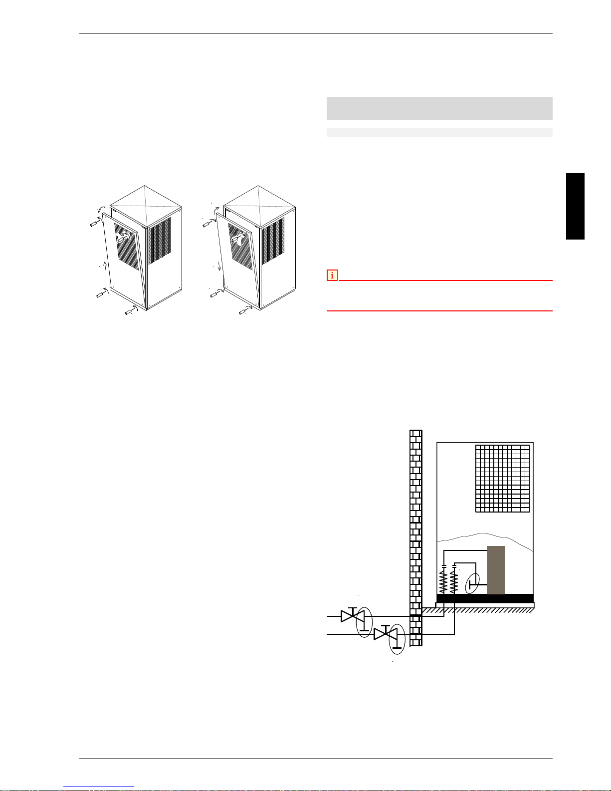
To open the device, loosen all 4 screws of each of the side pan-
els and withdraw them by unhooking them from below. Close the
device in the reverse order.
6.2 Heating System Connection
The heating system connections on the heat pump have a 1" ex-
ternal thread. Route the connection hoses out of the device in a
downwards direction. Use a spanner to firmly grip the transitions
when connecting the heat pump.
Before connecting the heating water system to the heat pump,
the heating system must be flushed to remove any impurities,
residue from sealants, etc. Any accumulation of deposits in the
liquifier could cause the heat pump to completely break down.
For systems in which the heating water flow can be shut off via
the radiator or thermostat valves, an overflow valve must be in-
stalled in a heating bypass behind the heat pump by the cus-
tomer. This ensures a minimum heating water flow rate through
the heat pump and helps to avoid faults.
Once the heating system has been installed, it must be filled, de-
aerated and pressure-tested.
Consideration must be given to the following when filling the sys-
tem:
Untreated filling water and make-up water must be of drink-
ing water quality (colourless, clear, free from sediments)
Filling water and make-up water must be pre-filtered (pore
size max. 5µm).
Scale formation in hot water heating systems cannot be com-
pletely avoided, but in systems with flow temperatures below
60°C the problem can be disregarded.
With medium and high-temperature heat pumps, temperatures
above 60°C can be reached.
The following standard values should therefore be adhered to
concerning the filling water and make-up water (according to VDI
2035 Sheet 1):
Minimum heating water flow rate
The minimum heating water flow rate through the heat pump
must be assured in all operating states of the heating sys-
tem. This can be accomplished, for example, by installing either
a dual differential pressureless manifold or an overflow valve.
The procedure for adjusting an overflow valve is described in the
Chapter Start-Up. When the minimum flow rate is undershot
drastically, the plate steel exchanger in the refrigerating cycle
can freeze, which can lead to total loss of the heat pump.
The use of an overflow valve is only recommended for panel heating and
a max. heating water flow of 1.3 m³/h. System faults may result if this is
not observed.
Antifreeze
Manual drainage (see illustration) should be provided for heat
pumps which are exposed to frost. The antifreeze function of the
heat pump manager is active whenever the heat pump manager
and the heat circulating pump are ready for operation. If the heat
pump manager is taken out of service or in the event of a power
failure, the system has to be drained. The heating circuit should
be operated with a suitable antifreeze if heat pump systems are
implemented in buildings where a power failure can not be de-
tected (holiday home).
Opening the cover Closing the cover