535589
275
Zoom out
Zoom in
Previous page
1/282
Next page
QuickScan™ I QD24XX
Product Reference Guide
General Purpose Handheld
Area Imager Bar Code Reader
Datalogic ADC, Inc.
959 Terry Street
Eugene, OR 97402
USA
Telephone: (541) 683-5700
Fax: (541) 345-7140
©2013 Datalogic ADC, Inc.
An Unpublished Work - All rights reserved. No part of the contents of this documentation or the
procedures described therein may be reproduced or transmitted in any form or by any means
with
out prior written permission of Datalogic ADC, Inc. or its subsidiaries or affiliates ("Datalogic"
or “Datalogic ADC”). Owners of Datalogic products are hereby granted a non-exclusive, revocable
license to reproduce and transmit this documentation for the purchaser's own internal business
purposes. Purchaser shall not remove or alter any proprietary notices, including copyright
notices, contained in this documentation and shall ensure that all notices appear on any repro-
ductions of the documentation.
Should future revisions of this manual be published, you can acquire printed versions by contact-
ing your Datalogic representative. Electronic versions may either be downloadable from the Dat-
alogic website (www.datalogic.com) or provided on appropriate media. If you visit our website
and would like to make comments or suggestions ab
out this or other Datalogic publications,
please let us know via the "Contact Datalogic" page.
Disclaimer
Datalogic has taken reasonable measures to provide information in this manual that is complete
and accurate, however, Datalogic reserves the right to change any specification at any time with-
out prior notice.
Datalogic and the Datalogic logo are registered trademarks of
Datalogic S.p.A. in many countries,
including the U.S.A. and the E.U. All other brand and product names may be trademarks of their
respective owners.
Patents
This product may be covered by one or more of
the following patents:
EP996284; EP997760; EP999514; EP1128315;
EP1396811; EP1413971; EP1828957; JP4435343B2;
US5481098; US6478224; US6512218; US6513714; US6561427; US6808114; US6997385;
US7053954; US7075663; US7234641; US7387246; US7721966.
Additional patents pending.
Product Reference Guide 1
Table of Contents
INTRODUCTION ................................................................................................................................................................................ 1
About this Manual .......................................................................................................................................................................................... 1
Overview .................................................................................................................................................................................................................................................... 1
Manual Conventions ............................................................................................................................................................................................................................. 2
Technical Support .......................................................................................................................................................................................... 2
Datalogic Website Support ................................................................................................................................................................................................................. 2
Reseller Technical Support .................................................................................................................................................................................................................. 2
Telephone Technical Support ............................................................................................................................................................................................................ 2
About the Reader ........................................................................................................................................................................................... 3
Programming the Reader .............................................................................................................................................................................. 4
Configuration Methods ........................................................................................................................................................................................................................ 4
SETUP ................................................................................................................................................................................................ 5
Unpacking ....................................................................................................................................................................................................... 5
Setting Up the Reader .................................................................................................................................................................................... 5
Installing the Interface Cable ........................................................................................................................................................................ 6
Interface Selection ......................................................................................................................................................................................... 8
Setting the Interface .............................................................................................................................................................................................................................. 9
Customizing Configuration Settings .......................................................................................................................................................... 12
Configure Interface Settings ............................................................................................................................................................................................................12
Global Interface Features ...................................................................................................................................................................................................................12
Configuring Other Features ..............................................................................................................................................................................................................12
Software Version Transmission .......................................................................................................................................................................................................12
Resetting the Product Configuration to Defaults .....................................................................................................................................................................13
CONFIGURATION USING BAR CODES............................................................................................................................................ 15
Configuration Parameters .................................................................................................................................................................................................................15
GLOBAL INTERFACE FEATURES .................................................................................................................................................. 17
Host Commands — Obey/Ignore .............................................................................................................................................................................17
USB Suspend Mode ........................................................................................................................................................................................................17
RS-232 Interface...................................................................................................................................................................... 19
Baud Rate ...........................................................................................................................................................................................................................20
Data Bits .............................................................................................................................................................................................................................21
Stop Bits ..............................................................................................................................................................................................................................21
Parity ....................................................................................................................................................................................................................................22
Handshaking Control ....................................................................................................................................................................................................23
RS-232/USB-Com Interfaces................................................................................................................................................... 24
Intercharacter Delay .......................................................................................................................................................................................................25
Beep On ASCII BEL ..........................................................................................................................................................................................................25
Beep On Not on File .......................................................................................................................................................................................................26
ACK NAK Options ............................................................................................................................................................................................................27
ACK Character ..................................................................................................................................................................................................................28
NAK Character ..................................................................................................................................................................................................................28
ACK NAK Timeout Value ...............................................................................................................................................................................................29
ACK NAK Retry Count ....................................................................................................................................................................................................29
ACK NAK Error Handling ...............................................................................................................................................................................................30
Indicate Transmission Failure .....................................................................................................................................................................................30
Disable Character ............................................................................................................................................................................................................31
Enable Character .............................................................................................................................................................................................................31
Keyboard Settings .................................................................................................................................................................. 33
Country Mode ..................................................................................................................................................................................................................34
Send Control Characters ..............................................................................................................................................................................................38
Wedge Quiet Interval ....................................................................................................................................................................................................39
Intercode Delay ...............................................................................................................................................................................................................39
Caps Lock State ................................................................................................................................................................................................................40
Numlock .............................................................................................................................................................................................................................40
Contents
2 QuickScan™ I QD24XX
USB Keyboard Speed .....................................................................................................................................................................................................41
USB Keyboard Numeric Keypad ................................................................................................................................................................................42
USB-OEM Interface ................................................................................................................................................................. 43
USB-OEM Device Usage ................................................................................................................................................................................................44
USB Interface Options ...................................................................................................................................................................................................44
Transmit Labels in Code 39 Format ..........................................................................................................................................................................45
Interface Options ............................................................................................................................................................................................................46
Data Format ............................................................................................................................................................................ 47
Global Prefix/Suffix ...................................................................................................................................................................................... 48
Global AIM ID ................................................................................................................................................................................................ 49
Set AIM ID Individually for GS1-128 ...............................................................................................................................................................................................51
Label ID .......................................................................................................................................................................................................... 52
Label ID: Pre-Loaded Sets ..................................................................................................................................................................................................................52
Individually Set Label ID .....................................................................................................................................................................................................................53
Label ID Control ...............................................................................................................................................................................................................53
Label ID Symbology Selection − 1D Symbologies ..............................................................................................................................................54
Advanced Formatting: User Label Edit ...................................................................................................................................................................59
Case Conversion ..............................................................................................................................................................................................................59
Character Conversion ....................................................................................................................................................................................................60
Reading Parameters ............................................................................................................................................................. 61
Double Read Timeout ...................................................................................................................................................................................................62
LED AND BEEPER INDICATORS ................................................................................................................................................... 64
Power On Alert .................................................................................................................................................................................................................64
Good Read: When to Indicate .....................................................................................................................................................................................64
Good Read Beep Type ...................................................................................................................................................................................................65
Good Read Beep Frequency .......................................................................................................................................................................................65
Good Read Beep Length ..............................................................................................................................................................................................66
Good Read Beep Volume .............................................................................................................................................................................................67
Good Read LED Duration .............................................................................................................................................................................................68
SCANNING FEATURES ................................................................................................................................................................. 69
Scan Mode .........................................................................................................................................................................................................................69
Stand Mode Indication ..................................................................................................................................................................................................70
Stand Operation ..............................................................................................................................................................................................................71
Pick Mode ..........................................................................................................................................................................................................................72
Stand Mode Sensitivity .................................................................................................................................................................................................72
Stand Mode Illumination Off Time ...........................................................................................................................................................................73
Scanning Active Time ....................................................................................................................................................................................................73
Stand Illumination Control ..........................................................................................................................................................................................74
Flash On Time ...................................................................................................................................................................................................................74
Flash Off Time ...................................................................................................................................................................................................................75
Aiming Pointer .................................................................................................................................................................................................................75
Aiming Duration Timer .................................................................................................................................................................................................76
Green Spot Duration ......................................................................................................................................................................................................77
Mobile Phone Mode ......................................................................................................................................................................................................77
Partial Label Reading Control .....................................................................................................................................................................................78
Decode Negative Image ...............................................................................................................................................................................................78
Image Capture .................................................................................................................................................................................................................78
MULTIPLE LABEL READING ......................................................................................................................................................... 79
Multiple Labels per Frame ...........................................................................................................................................................................................79
Multiple Labels Ordering by Code Symbology ....................................................................................................................................................80
Multiple Labels Ordering by Code Length ............................................................................................................................................................80
1D Symbologies...................................................................................................................................................................... 81
1D Code Selection ........................................................................................................................................................................................ 81
DISABLE ALL SYMBOLOGIES ...................................................................................................................................................... 82
CODE EAN/UPC ............................................................................................................................................................................ 83
Coupon Control ...............................................................................................................................................................................................................83
UPC-A ..................................................................................................................................................................................................................................84
UPC-A Enable/Disable ...................................................................................................................................................................................................84
UPC-A Check Character Transmission .....................................................................................................................................................................84
Expand UPC-A to EAN-13 .............................................................................................................................................................................................85
UPC-A Number System Character Transmission .................................................................................................................................................85
UPC-A 2D Component ..................................................................................................................................................................................................86
Contents
Product Reference Guide 3
UPC-E ............................................................................................................................................................................................ 86
UPC-E Enable/Disable ....................................................................................................................................................................................................86
UPC-E Check Character Transmission ......................................................................................................................................................................87
UPC-E 2D Component ...................................................................................................................................................................................................87
Expand UPC-E to EAN-13 .............................................................................................................................................................................................88
Expand UPC-E to UPC-A ...............................................................................................................................................................................................88
UPC-E Number System Character Transmission ..................................................................................................................................................89
GTIN FORMATTING ...................................................................................................................................................................... 89
EAN 13 (JAN 13) ........................................................................................................................................................................... 90
EAN 13 Enable/Disable .................................................................................................................................................................................................90
EAN 13 Check Character Transmission ...................................................................................................................................................................90
EAN-13 Flag 1 Character ...............................................................................................................................................................................................91
EAN-13 ISBN Conversion ..............................................................................................................................................................................................91
EAN-13 2D Component ................................................................................................................................................................................................92
ISSN .............................................................................................................................................................................................. 92
ISSN Enable/Disable .......................................................................................................................................................................................................92
EAN 8 (JAN 8) ............................................................................................................................................................................... 93
EAN 8 Enable/Disable ....................................................................................................................................................................................................93
EAN 8 Check Character Transmission ......................................................................................................................................................................93
Expand EAN 8 to EAN 13 ..............................................................................................................................................................................................94
EAN 8 2D Component ...................................................................................................................................................................................................94
UPC/EAN GLOBAL SETTINGS ...................................................................................................................................................... 95
UPC/EAN Price Weight Check .....................................................................................................................................................................................95
UPC/EAN Quiet Zones ...................................................................................................................................................................................................96
ADD-ONS ...................................................................................................................................................................................... 97
Optional Add-ons ...........................................................................................................................................................................................................97
Optional Add-On Timer ................................................................................................................................................................................................98
Optional GS1-128 Add-On Timer ........................................................................................................................................................................... 101
CODE 39 ......................................................................................................................................................................................104
Code 39 Enable/Disable ............................................................................................................................................................................................ 104
Code 39 Check Character Calculation .................................................................................................................................................................. 104
Code 39 Check Character Transmission .............................................................................................................................................................. 105
Code 39 Start/Stop Character Transmission ...................................................................................................................................................... 106
Code 39 Full ASCII ........................................................................................................................................................................................................ 106
Code 39 Quiet Zones .................................................................................................................................................................................................. 107
Code 39 Length Control ............................................................................................................................................................................................ 107
Code 39 Set Length 1 ................................................................................................................................................................................................. 108
Code 39 Set Length 2 ................................................................................................................................................................................................. 109
TRIOPTIC CODE ..........................................................................................................................................................................110
Trioptic Code Enable/Disable .................................................................................................................................................................................. 110
CODE 32 (ITAL PHARMACEUTICAL CODE) ...............................................................................................................................110
Code 32 Enable/Disable ............................................................................................................................................................................................ 110
Code 32 Feature Setting Exceptions ..................................................................................................................................................................... 111
Code 32 Check Char Transmission ........................................................................................................................................................................ 111
Code 32 Start/Stop Character Transmission ...................................................................................................................................................... 111
CODE 39 CIP (FRENCH PHARMACEUTICAL) .............................................................................................................................112
Code 39 CIP Enable/Disable ..................................................................................................................................................................................... 112
CODE 39 DANISH PPT ................................................................................................................................................................112
Code 39 Danish PPT Enable/Disable ..................................................................................................................................................................... 112
CODE 39 LAPOSTE .....................................................................................................................................................................113
Code 39 LaPoste Enable/Disable ............................................................................................................................................................................ 113
CODE 39 PZN ..............................................................................................................................................................................113
Code 39 PZN Enable/Disable ................................................................................................................................................................................... 113
CODE 128 ...................................................................................................................................................................................114
Code 128 Enable/Disable .......................................................................................................................................................................................... 114
Expand Code 128 to Code 39 .................................................................................................................................................................................. 114
Code 128 Check Character Transmission ............................................................................................................................................................ 115
Code 128 Function Character Transmission ...................................................................................................................................................... 115
Code 128 Quiet Zones ................................................................................................................................................................................................ 116
Code 128 Length Control .......................................................................................................................................................................................... 116
Code 128 Set Length 1 ............................................................................................................................................................................................... 117
Code 128 Set Length 2 ............................................................................................................................................................................................... 118
Contents
4 QuickScan™ I QD24XX
GS1-128 ......................................................................................................................................................................................119
GS1-128 Enable ............................................................................................................................................................................................................. 119
GS1-128 2D Component ........................................................................................................................................................................................... 119
CODE ISBT 128 ...........................................................................................................................................................................120
ISBT 128 Concatenation ............................................................................................................................................................................................ 120
ISBT 128 Force Concatenation ................................................................................................................................................................................ 120
ISBT 128 Concatenation Mode ................................................................................................................................................................................ 121
ISBT 128 Dynamic Concatenation Timeout ........................................................................................................................................................ 122
ISBT 128 Advanced Concatenation Options ...................................................................................................................................................... 123
INTERLEAVED 2 OF 5 (I 2 OF 5) .................................................................................................................................................123
I 2 of 5 Enable/Disable ................................................................................................................................................................................................ 123
I 2 of 5 Check Character Calculation ..................................................................................................................................................................... 124
I 2 of 5 Check Character Transmission .................................................................................................................................................................. 125
I 2 of 5 Length Control ............................................................................................................................................................................................... 125
I 2 of 5 Set Length 1 ..................................................................................................................................................................................................... 126
I 2 of 5 Set Length 2 ..................................................................................................................................................................................................... 127
INTERLEAVED 2 OF 5 CIP HR .....................................................................................................................................................128
Interleaved 2 of 5 CIP HR Enable/Disable ............................................................................................................................................................ 128
FOLLETT 2 OF 5 ..........................................................................................................................................................................128
Follett 2 of 5 Enable/Disable .................................................................................................................................................................................... 128
STANDARD 2 OF 5 .....................................................................................................................................................................129
Standard 2 of 5 Enable/Disable .............................................................................................................................................................................. 129
Standard 2 of 5 Check Character Calculation .................................................................................................................................................... 129
Standard 2 of 5 Check Character Transmission ................................................................................................................................................. 130
Standard 2 of 5 Length Control .............................................................................................................................................................................. 130
Standard 2 of 5 Set Length 1 ................................................................................................................................................................................... 131
Standard 2 of 5 Set Length 2 ................................................................................................................................................................................... 132
INDUSTRIAL 2 OF 5 ....................................................................................................................................................................133
Industrial 2 of 5 Enable/Disable .............................................................................................................................................................................. 133
Industrial 2 of 5 Check Character Calculation .................................................................................................................................................... 133
Industrial 2 of 5 Check Character Transmission ................................................................................................................................................ 134
Industrial 2 of 5 Length Control .............................................................................................................................................................................. 134
Industrial 2 of 5 Set Length 1 ................................................................................................................................................................................... 135
Industrial 2 of 5 Set Length 2 ................................................................................................................................................................................... 136
CODE IATA ..................................................................................................................................................................................137
IATA Enable/Disable ................................................................................................................................................................................................... 137
IATA Check Character Transmission ..................................................................................................................................................................... 137
CODABAR ...................................................................................................................................................................................138
Codabar Enable/Disable ............................................................................................................................................................................................ 138
Codabar Check Character Calculation .................................................................................................................................................................. 138
Codabar Check Character Transmission .............................................................................................................................................................. 139
Codabar Start/Stop Character Transmission ...................................................................................................................................................... 139
Codabar Start/Stop Character Set .......................................................................................................................................................................... 140
Codabar Start/Stop Character Match ................................................................................................................................................................... 140
Codabar Quiet Zones .................................................................................................................................................................................................. 141
Codabar Length Control ............................................................................................................................................................................................ 141
Codabar Set Length 1 ................................................................................................................................................................................................. 142
Codabar Set Length 2 ................................................................................................................................................................................................. 143
ABC CODABAR ...........................................................................................................................................................................144
ABC Codabar Enable/Disable .................................................................................................................................................................................. 144
ABC Codabar Concatenation Mode ...................................................................................................................................................................... 144
ABC Codabar Dynamic Concatenation Timeout .............................................................................................................................................. 145
ABC Codabar Force Concatenation ....................................................................................................................................................................... 146
CODE 11 ......................................................................................................................................................................................147
Code 11 Enable/Disable ............................................................................................................................................................................................ 147
Code 11 Check Character Calculation .................................................................................................................................................................. 147
Code 11 Check Character Transmission .............................................................................................................................................................. 148
Code 11 Length Control ............................................................................................................................................................................................ 148
Code 11 Set Length 1 ................................................................................................................................................................................................. 149
Code 11 Set Length 2 ................................................................................................................................................................................................. 150
GS1 DATABAR™ OMNIDIRECTIONAL .......................................................................................................................................151
GS1 DataBar™ Omnidirectional Enable/Disable ............................................................................................................................................... 151
Contents
Product Reference Guide 5
GS1 DataBar™ Omnidirectional GS1-128 Emulation ....................................................................................................................................... 151
GS1 DataBar™ Omnidirectional 2D Component .............................................................................................................................................. 152
GS1 DATABAR™ EXPANDED .....................................................................................................................................................152
GS1 DataBar™ Expanded Enable/Disable ............................................................................................................................................................ 152
GS1 DataBar™ Expanded GS1-128 Emulation ................................................................................................................................................... 153
GS1 DataBar™ Expanded 2D Component ........................................................................................................................................................... 153
GS1 DataBar™ Expanded Length Control ........................................................................................................................................................... 154
GS1 DataBar™ Expanded Set Length 1 ................................................................................................................................................................. 155
GS1 DataBar™ Expanded Set Length 2 ................................................................................................................................................................. 156
GS1 DATABAR™ LIMITED ..........................................................................................................................................................157
GS1 DataBar™ Limited Enable/Disable ................................................................................................................................................................. 157
GS1 DataBar™ Limited GS1-128 Emulation ........................................................................................................................................................ 157
GS1 DataBar™ Limited 2D Component ................................................................................................................................................................ 158
CODE 93 ......................................................................................................................................................................................158
Code 93 Enable/Disable ............................................................................................................................................................................................ 158
Code 93 Check Character Calculation .................................................................................................................................................................. 159
Code 93 Check Character Transmission .............................................................................................................................................................. 159
Code 93 Length Control ............................................................................................................................................................................................ 160
Code 93 Set Length 1 ................................................................................................................................................................................................. 161
Code 93 Set Length 2 ................................................................................................................................................................................................. 162
Code 93 Quiet Zones .................................................................................................................................................................................................. 163
MSI ..............................................................................................................................................................................................163
MSI Enable/Disable ...................................................................................................................................................................................................... 163
MSI Check Character Calculation ........................................................................................................................................................................... 164
MSI Check Character Transmission ........................................................................................................................................................................ 164
MSI Length Control ..................................................................................................................................................................................................... 165
MSI Set Length 1 .......................................................................................................................................................................................................... 166
MSI Set Length 2 .......................................................................................................................................................................................................... 167
PLESSEY ......................................................................................................................................................................................168
Plessey Enable/Disable .............................................................................................................................................................................................. 168
Plessey Check Character Calculation .................................................................................................................................................................... 168
Plessey Check Character Transmission ................................................................................................................................................................ 169
Plessey Length Control .............................................................................................................................................................................................. 169
Plessey Set Length 1 ................................................................................................................................................................................................... 170
Plessey Set Length 2 ................................................................................................................................................................................................... 171
2D Symbologies.................................................................................................................................................................... 173
2D Global Features .....................................................................................................................................................................................173
2D Maximum Decoding Time ....................................................................................................................................................................................................... 174
2D Structured Append .................................................................................................................................................................................................................... 175
2D Normal/Inverse Symbol Control ............................................................................................................................................................................................ 175
Aztec Code ..................................................................................................................................................................................................176
Aztec Code Enable / Disable .......................................................................................................................................................................................................... 176
Aztec Code Length Control ........................................................................................................................................................................................................... 176
Aztec Code Set Length 1 ........................................................................................................................................................................................... 177
Aztec Code Set Length 2 ........................................................................................................................................................................................... 178
China Sensible Code ...................................................................................................................................................................................179
China Sensible Code Enable / Disable ....................................................................................................................................................................................... 179
China Sensible Code Length Control ......................................................................................................................................................................................... 179
China Sensible Code Set Length 1 ......................................................................................................................................................................... 180
China Sensible Code Set Length 2 ......................................................................................................................................................................... 181
Data Matrix .................................................................................................................................................................................................182
Data Matrix Enable / Disable ......................................................................................................................................................................................................... 182
Data Matrix Square/Rectangular Style ....................................................................................................................................................................................... 182
Data Matrix Length Control ........................................................................................................................................................................................................... 183
Data Matrix Set Length 1 ........................................................................................................................................................................................... 183
Data Matrix Set Length 2 ........................................................................................................................................................................................... 184
Maxicode .....................................................................................................................................................................................................185
Maxicode Enable / Disable ............................................................................................................................................................................................................. 185
Maxicode Primary Message Transmission ................................................................................................................................................................................ 185
Maxicode Length Control ............................................................................................................................................................................................................... 186
Maxicode Set Length 1 .............................................................................................................................................................................................. 186
Maxicode Set Length 2 .............................................................................................................................................................................................. 187
Contents
6 QuickScan™ I QD24XX
PDF417 ........................................................................................................................................................................................................188
PDF417 Enable / Disable ................................................................................................................................................................................................................. 188
PDF417 Length Control ................................................................................................................................................................................................................... 188
PDF417 Set Length 1 .................................................................................................................................................................................................. 189
PDF417 Set Length 2 .................................................................................................................................................................................................. 190
Micro PDF417 ..............................................................................................................................................................................................191
Micro PDF417 Enable / Disable .................................................................................................................................................................................................... 191
Micro PDF417 Code 128 GS1-128 Emulation .......................................................................................................................................................................... 191
Micro PDF417 Length Control ...................................................................................................................................................................................................... 192
Micro PDF417 Set Length 1 ...................................................................................................................................................................................... 192
Micro PDF417 Set Length 2 ...................................................................................................................................................................................... 193
QR Code .......................................................................................................................................................................................................194
QR Code Enable / Disable ............................................................................................................................................................................................................... 194
QR Code Length Control ................................................................................................................................................................................................................. 194
QR Code Set Length 1 ................................................................................................................................................................................................ 195
QR Code Set Length 2 ................................................................................................................................................................................................ 196
Micro QR Code ............................................................................................................................................................................................197
Micro QR Code Enable/Disable .................................................................................................................................................................................................... 197
Micro QR Code Length Control .................................................................................................................................................................................................... 197
Micro QR Code Set Length 1 .................................................................................................................................................................................... 198
Micro QR Code Set Length 2 .................................................................................................................................................................................... 199
UCC Composite ...........................................................................................................................................................................................200
UCC Composite Enable / Disable ................................................................................................................................................................................................. 200
UCC Optional Composite Timer ................................................................................................................................................................................................... 201
Postal Code Selection .................................................................................................................................................................................202
Postnet BB Control ............................................................................................................................................................................................................................ 203
REFERENCES................................................................................................................................................................................. 205
RS-232 Parameters .....................................................................................................................................................................................206
RS-232 .................................................................................................................................................................................................................................................... 206
RS-232/USB COM Parameters ....................................................................................................................................................................................................... 207
Keyboard Interface .....................................................................................................................................................................................214
Wedge Quiet Interval ....................................................................................................................................................................................................................... 214
Intercharacter Delay ......................................................................................................................................................................................................................... 215
Intercode Delay .................................................................................................................................................................................................................................. 216
Symbologies ...............................................................................................................................................................................................217
Set Length ............................................................................................................................................................................................................................................ 217
Data Editing ................................................................................................................................................................................................218
Global Prefix/Suffix ........................................................................................................................................................................................................................... 219
Global AIM ID ...................................................................................................................................................................................................................................... 220
Label ID ................................................................................................................................................................................................................................................. 221
Character Conversion ...................................................................................................................................................................................................................... 226
Reading Parameters ...................................................................................................................................................................................227
Good Read LED Duration ................................................................................................................................................................................................................ 227
Scanning Features ......................................................................................................................................................................................228
Scan Mode ........................................................................................................................................................................................................................................... 228
Stand Mode Off Time ....................................................................................................................................................................................................................... 229
Scanning Active Time ...................................................................................................................................................................................................................... 230
Aiming Duration Time ..................................................................................................................................................................................................................... 231
Flash On Time ..................................................................................................................................................................................................................................... 232
Flash Off Time ..................................................................................................................................................................................................................................... 233
Multiple Labels Ordering by Code Symbology ...................................................................................................................................................................... 234
TECHNICAL SPECIFICATIONS...................................................................................................................................................... 237
Imager Labeling ..........................................................................................................................................................................................241
Standard Cable Pinouts .............................................................................................................................................................................242
LED and Beeper Indications .......................................................................................................................................................................243
Error Codes ..................................................................................................................................................................................................244
Contents
Product Reference Guide 7
STANDARD DEFAULTS................................................................................................................................................................ 245
SAMPLE BAR CODES.................................................................................................................................................................... 255
KEYPAD ........................................................................................................................................................................................ 259
SCANCODE TABLES ..................................................................................................................................................................... 261
Control Character Emulation .....................................................................................................................................................................261
Single Press and Release Keys ....................................................................................................................................................................................................... 261
Interface Type PC AT PS/2, USB-Keyboard or USB-Keyboard for APPLE ...............................................................................................262
Interface type PC AT PS/2 Alt Mode or USB-Keyboard Alt Mode ...........................................................................................................264
Digital Interface ..........................................................................................................................................................................................266
IBM31xx 102-key ........................................................................................................................................................................................267
IBM XT ..........................................................................................................................................................................................................268
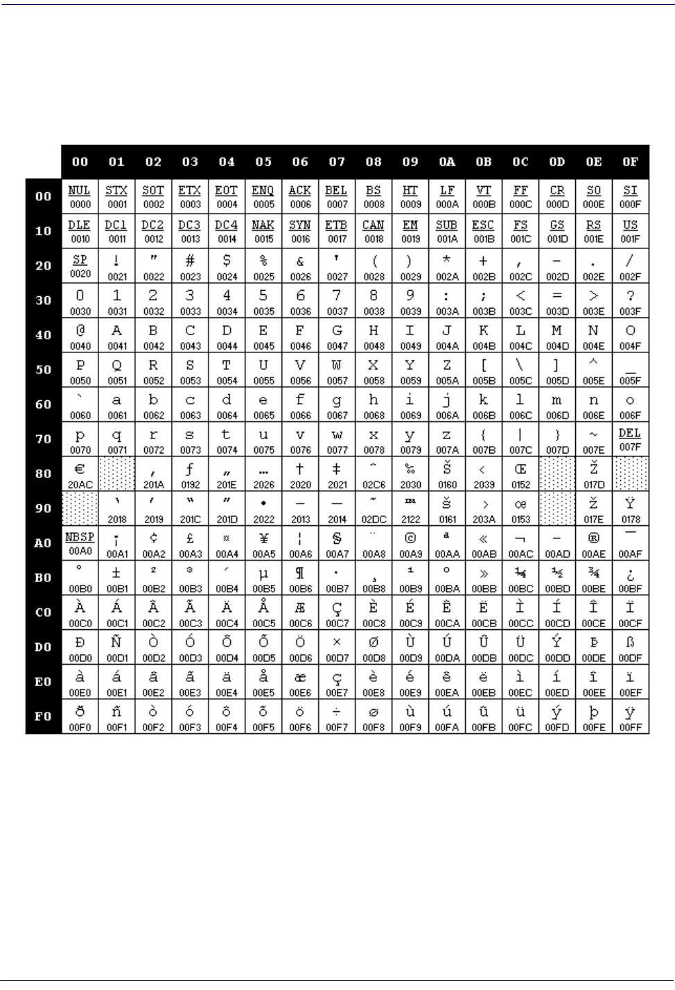
Microsoft Windows Codepage 1252 .........................................................................................................................................................269
Contents
8 QuickScan™ I QD24XX
NOTES
Product Reference Guide 1
Chapter 1
Introduction
About this Manual
This Product Reference Guide (PRG) is provided for users seeking advanced technical information, including
connection, programming, maintenance and specifications. The Quick Reference Guide (QRG) and other
publications associated with this product are downloadable free of charge from the website listed on the back cover
of this manual.
Overview
Chapter 1, (this chapter) presents information about manual conventions, and an overview of the reader, its
features and operation.
Chapter 2, Setup presents information about unpacking, cable connection
information and setting up the reader.
Chapter 3, Configuration Using Bar Codes provides instructions and bar code labels for customizing your reader.
There are different sections for interface types, general
features, data formatting, symbology-specific and model-
specific features.
Chapter 4, References contains additional information and examples for selected bar code features.
Appendix A, Technical Specifications lists physical and performance characteristics, as well
as environmental and
regulatory specifications. It also provides standard cable pinouts and LED/Beeper functions
.
Appendix B, Standard Defaults references common factory default settings for reader
features and options.
Appendix C, Sample Bar Codes offers sample bar codes for several common symbologies.
Appendix D, Keypad includes numeric bar codes to be scanned for certain parameter settings.
Appendix E, Scancode Tables lists control character emulation information for Wedge and
USB Keyboard
interfaces.
Technical Support
2 QuickScan™ I QD24XX
Manual Conventions
The following conventions are used in this document:
The symbols listed below are used in this
manual to notify the reader of key issues or procedures that must be
observed when using the reader:
Notes contain information necessary for properly diagnosing, repairing and operating the
reader.
CAUTION
The CAUTION symbol advises you of actions that could damage equipment or property.
Current versions of this Product Reference Guide (PRG), Quick Reference Guide (QRG), the Datalogic
Aladdin™ Configuration application, and any other manuals, instruction sheets and utilities for this product can
be downloaded from the website listed below. Alternatively, printed copies or product support CDs for most
products can be purchased through your Datalogic reseller.
Technical Support
Datalogic Website Support
The Datalogic website (www.datalogic.com) is the complete source for technical support and information for
Datalogic products. The site offers product support, warranty information, product manuals, product
tech notes,
software updates, demos, and instructions for returning products for repair.
Reseller Technical Support
An excellent source for technical assistance and information is an authorized Datalogic reseller. A reseller is
acquainted with specific types of businesses, application software, and computer systems and can provide
individualized assistance.
Telephone Technical Support
If you do not have internet or email access, you may contact Datalogic technical support at (541) 349-8283 or
check the back cover of your manual for more contact information.
About the Reader
Product Reference Guide 3
About the Reader
The QuickScan™ QD2400 2D Imager was specifically created to address the needs of retailers and meet the
market demand with outstanding omni-directional reading performance on virtually all codes at an affordable
price. Elegant design details are incorporated into a smaller, balanced lightweight enclosure without sacrificing
Datalogic’s well-known durability.
Ideally suited for applications at the point of-sale (P
OS), the QuickScan QD2400 imager features a new
illumination and aiming system developed with the unique intent to reduce visual stress of the operator during the
daily scanning activities. It consists of a soft, dark red illumination combined with two blue LED triangles pointing
at the targeted bar code.
The result is a precise aiming system whic
h contributes to low eye fatigue, yet still allows top operator efficiency.
The QuickScan QD2400 imager reads typical printed linear bar cod
es as well as complex 2D bar codes displayed
on the screen of a mobile device or loyalty cards. The QD2400 imager provides a fast, reliable scan from an elegant
and robust 2D imager.
Imaging technology meets or exceeds the productivity compared to laser
scanners and provides the additional
advantages of a lower cost-of-ownership and greater product reliability over the long term.
Programming the Reader
4 QuickScan™ I QD24XX
Programming the Reader
Configuration Methods
Programming Bar Codes
The reader is factory-configured with a standard set of default features. After scanning the interface bar code, you
can select other options and customize your reader through use of the instructions and programming bar code
labels available in the corresponding features section for your interface. Customizable settings for many features are
found in "Configuration Parameters" start
ing on page 15.
Some programming labels, like "Restore Custom Defaults" on page 13, require only the scan of the s
ingle label to
enact the change. Most, however, require the reader to be placed in Programming Mode pr
ior to scanning them.
Scan an ENTER/EXIT bar code once to enter Programming Mode. Once the reader is in Programming Mode,
scan a number of parameter settings before scanning the ENTER/EXIT bar code a second time, which will then
accept your changes, exit Programming Mode and return the reader to normal operation.
There are some exceptions to the typical programming sequence described above. Please read the
description and setting instructions carefully when configuring each programmable feature.
Datalogic Aladdin™
Datalogic Aladdin™ is a multi-platform utility program providing a quick and user-friendly configuration method
via the RS-232/USB-COM interface. Aladdin is available for download free of charge on the Datalogic website.
Aladdin allows you to program the reader by selecting configuration commands through a user-friendly graphical
interface running on a PC. These commands are sent to the reader over the selected communication interface, or
they can be printed as bar codes to be scanned.
Aladdin also provides the ability to perform a software upgrade
for the connected device (see the Datalogic
Aladdin™ Help On-Line for more details).
Product Reference Guide 5
Chapter 2
Setup
Unpacking
Check carefully to ensure the reader and any accessories ordered are present and undamaged. If any damage
occurred during shipment, contact Datalogic Technical Support. Information is shown on page 2.
KEEP THE PACKAGING. Should the unit ever require service
, it should be returned in its original shipping
container.
Setting Up the Reader
ollow the steps provided in this section to connect and get your reader up and communicating with its host.
1. Begin by Installing the Interface Cable
2. Go to Interface Selection and set the desired interface.
3. Configure Interface Settings (only if not using factory settings for that interface).
4. Go to Configuring Other Features (if modifications are needed from factory settings).
Setup
6 QuickScan™ I QD24XX
Installing the Interface Cable
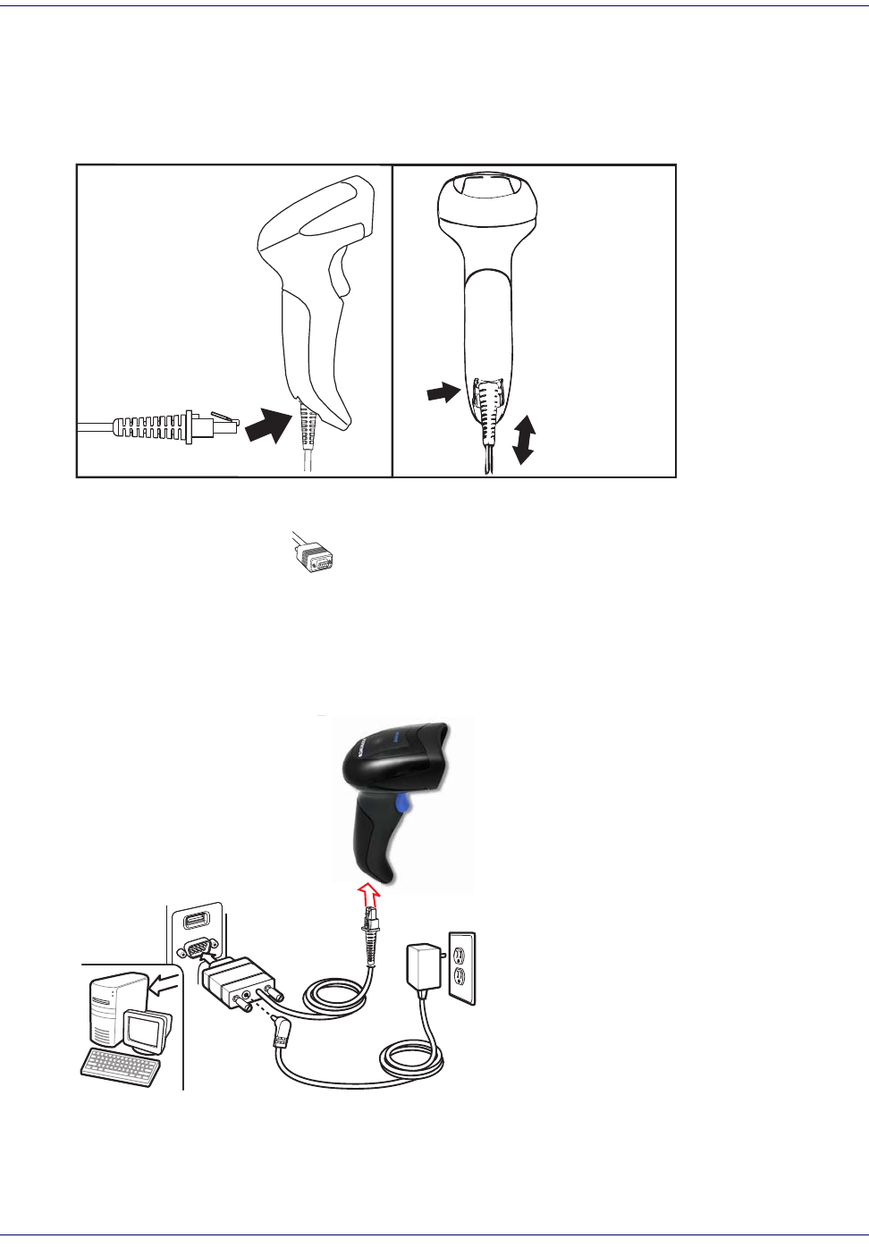
onnect the reader cable by inserting the cable into the handle as shown in Figure 1. To remove it, insert a paper clip
into the release aperture, then unplug the cable.
Figure 1. Connect/disconnect the cable
RS-232 Serial Connection
Turn off power to the terminal/PC and connect the reader to the terminal/PC serial port via the RS-232 cable as
shown in Figure 2. If the terminal will not support POT (Power Off the T
erminal) to supply reader power, use the
approved power supply (AC Adapter). Plug the AC Adapter barrel connector into the socket on the RS-232 cable
connector and the AC Adapter plug into a standard power outlet.
Figure 2. RS-232 Connection
Installing the Interface Cable
Product Reference Guide 7
Keyboard Wedge Connection
The Keyboard Wedge cable has a ‘Y’ connection from the reader. Connect the female to the male end from the
keyboard and the remaining end at the keyboard port at the terminal/PC. Reference Figure 3.
Figure 3. Keyboard Wedge Interface connection
USB Connection
Connect the reader to a USB port on the terminal/PC using the correct USB cable for the interface type you
ordered. Reference Figure 4.
Figure 4. USB connection
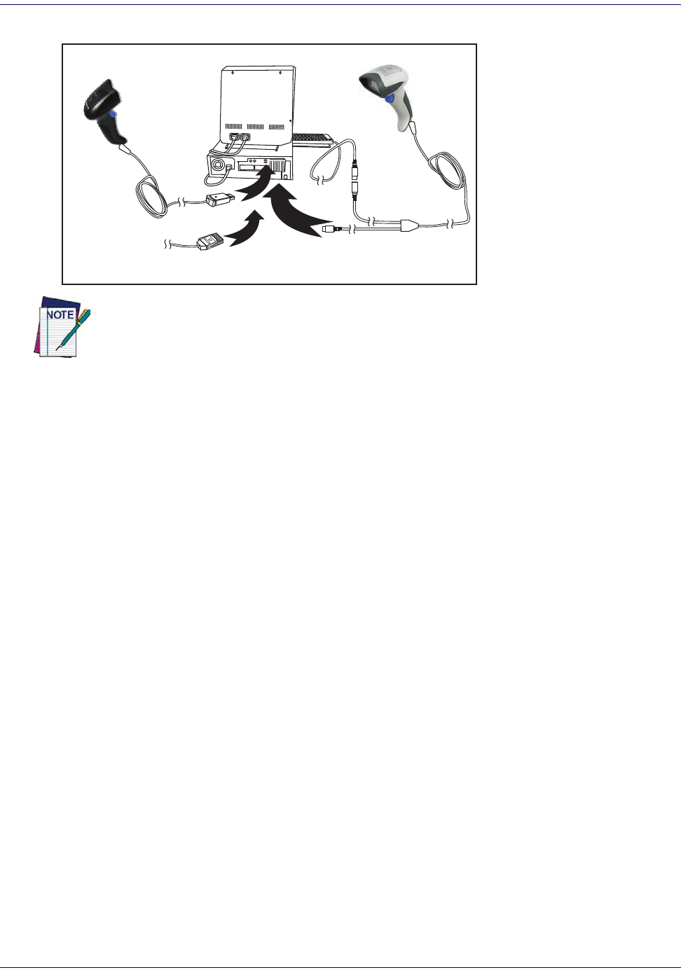
Other connection types are described below and illustrated in Figure 5.
Setup
8 QuickScan™ I QD24XX
Figure 5. Other Interface Connections
W
a
n
d
I
B
M
K
e
y
b
o
a
r
d
W
e
d
g
e
or...
or...
Specific cables are required for connection to different hosts. The connectors illustrated
above are examples only. Actual connectors may vary from those illustrated, but the steps to
connect the reader remain the same.
Interface Selection
Upon completing the physical connection between the reader and its host, proceed to Table 1 starting on page 9 to
select the interface type the reader is connected to (for example: RS-232, Keyboard Wedge, USB, etc.). Scan the
appropriate bar code in that section to configure your
system’s correct interface type.
Each reader model will support one of the following sets of host interfaces:
Ge
neral Purpose Models Retail Point of Sale Models
•RS-232
RS-232 OPOS
•USB-COM
Keyboard Wedge
•RS-232
RS-232 OPOS
•USB
Interface Selection
Product Reference Guide 9
Setting the Interface
Scan the programming bar code from this section which selects the appropriate interface type matching the system
the reader will be connected to. Next, proceed to the corresponding section in this manual (also listed in Tab le 1 on
page 9) to configure any desired settings and features associated with that interface.
Unlike some programming features and options, interface selections require that you
scan only one programming bar code label. DO NOT scan an ENTER/EXIT bar code prior to
scanning an interface selection bar code.
Some interfaces require the scanner to start in the disabl
ed state when powered up. If
additional scanner configuration is desired while in this state, pull the trigger and hold it
for five seconds. The scanner will change to a state that allows programming with bar
codes.
Table 1. Available Interfaces
RS-232 FEATURES
RS-232 standard interface
Select RS232-STD
Set RS-232
Interface
Features
starting on
page 19
$P,HA12,P(CR)
Select RS232-WN
RS-232 Wincor-Nixdorf
RS-232 for use with OPOS/UPOS/JavaPOS
$P,HA13,P(CR)
Select RS-232 OPOS
$P,HA47,P(CR)
Select USB-COM-STD
a
a. Download the correct USB Com driver from www.datalogic.com
USB Com to simulate RS-232 standard interface
USB-OEM FEATURES
$P,HA45,P(CR)
Select USB-OEM
USB-OEM
(can be used for OPOS/UPOS/JavaPOS)
Set USB-OEM
Interface
Features
starting on
page 43
KEYBOARD FEATURES
$P,HA2B,P(CR)
Select USB Alternate Keyboard
USB Keyboard with alternate key encoding
AT, PS/2 25-286, 30-286, 50, 50Z, 60, 70,
80, 90 & 95 w/Standard Key Encoding
$P,HA29,P(CR)
Select KBD-AT
Set KEYBOARD
WEDGE
Interface
Features
starting on
page 33
$P,HA11,P(CR)
Select KBD-AT-NK
Keyboard Wedge for IBM AT PS2 with
standard key encoding but without
external keyboard
AT, PS/2 25-286, 30-286, 50, 50Z, 60, 70,
80, 90
& 95 w/Alternate Key
$P,HA26,P(CR)
Select KBD-AT-ALT
$P,HA10,P(CR)
Select KBD-AT-ALT-NK
Keyboard Wedge for IBM AT PS2 with
alternate key encoding but without
external keyboard
PC/XT w/Standard Key Encoding
$P,HA28,P(CR)
Select KBD-XT
$P,HA14,P(CR)
Select KBD-IBM-3153
Keyboard Wedge for IBM Terminal 3153
Setup
10 QuickScan™ I QD24XX
KEYBOARD (continued) FEATURES
Keyboard Wedge for IBM Terminals
31xx, 32xx, 34xx, 37xx make
only key-
board
$P,HA15,P(CR)
Select KBD-IBM-M
Set KEYBOARD
WEDGE
Interface
Features
starting on page
33
$P,HA16,P(CR)
Select KBD-IBM-MB
Keyboard Wedge for IBM Terminals
31xx, 32xx, 34xx, 37xx make break key-
board
Keyboard Wedge for DIGITAL
Terminals VT2xx, VT3xx, VT4xx
$P,HA1B,P(CR)
Select KBD-DIG-VT
$P,HA35,P(CR)
Select USB Keyboard
USB Keyboard with standard key encoding
USB Keyboard for Apple computers
$P,HA2C,P(CR)
Select USB-KBD-APPLE
Interface Selection
Product Reference Guide 11
Setup
12 QuickScan™ I QD24XX
Customizing Configuration Settings
Configure Interface Settings
If after scanning the interface bar code from the previous table, your installation requires you to select options to
further customize your reader, turn to the appropriate section for your interface type in "Configuration
Parameters" start
ing on page 15.
"RS-232 Interface" on page 19
"RS-232/USB-Com Interfaces" on page 24
"Keyboard Settings" on page 33
Global Interface Features
See "Global Interface Features" on page 17 for settings configurable by all interface types.
Configuring Other Features
If your installation requires different programming than the standard factory default settings, the following sections
of this manual allow configuration of non-interface-specific settings you might require:
Data Format
:
Data Format offers options to control the messages sent to the Host system.
Reading Parameters
:
Reading Parameters include programming for scanning, beeper and LED indicators and other
universal settings.
Symbology-Specific Parameters
1D Symbologies
:
Includes options concerning the bar code label types (symbologies). These settings allow you to
enable/disable symbologies, set label lengths, require check digit, etc.
2D Symbologies
:
Includes options concerning the bar code label types (symbologies). These settings allow you to
enable/disable symbologies, set label lengths, require check digit, etc.
Software Version Transmission
The software version of the device can be transmitted over the RS-232 and Keyboard interfaces by scanning the
following label.
Transmit Software Version
RevA
Customizing Configuration Settings
Product Reference Guide 13
Resetting the Product Configuration to Defaults
Restore Custom Defaults
If you aren’t sure what programming options are in your imager, or you’ve changed some options and want to
restore the Custom Default Configuration that may have been saved in the scanner, scan the Restore Custom
Default Configuration bar code below. This will restore the custom configuration for the currently active interface.
Restore Custom Default Configuration
$P,HA00,P(CR)
Custom defaults are based on the interface type. Configure the imager for the correct
interface before scanning this label.
Restore Factory Configuration
If you want to restore the Factory Configuration for your imager, scan either the Restore USA Factory
Configuration bar code or the Restore EU Factory Configuration bar code below. Both labels restore the scanner
configuration to the factory settings, including the interface type. The USA label restores Label IDs to those
historically used in the USA. The EU label restores Label IDs to those historically used in Europe. The Label ID
sets for USA and EU are shown in the “Label ID Control” section on page 53 of this manual.
Restore USA Factory Configuration
$P,Ae,P(CR)
Restore EU Factory Configuration
The programming items listed in the following sections show the factory default settings for each of the menu
commands.
Setup
14 QuickScan™ I QD24XX
NOTES
Product Reference Guide 15
Chapter 3
Configuration Using Bar Codes
This and following sections provide programming bar codes to configure your reader by changing the default
settings. For details about additional methods of programming, see "Configuration Me
thods" on page 4.
You must first enable your reader to read bar codes in order to use this section. If you have not
done this, go to
Setup, starting on page 5
and complete the appropriate procedure.
Configuration Parameters
Once the reader is set up, you can change the default parameters to meet your application needs. Refer to "Standard
Defaults" starting on page 24
5 for initial configuration in order to set the default values and select the interface for
your application.
The following configuration parameters are divided into logical groups, makin
g
it easy to find the desired function
based on its reference group.
Interface Configuration:
"RS-232/USB-Com Interfaces" on page 24
"Keyboard Settings" on page 33
Parameters common to all interface applications:
"Data Format" on page 47 gives options to control the messages sent to the Host system.
"Reading Parameters" on page 61 control various operating modes and indicators status functioning.
Symbology-specific parameters:
"1D Symbologies" on page 81 provides configuration of a personalized mix of 1D codes, code families and
their options.
"2D Symbologies" on page 173 provides configuration of a personalized mix of 2D codes, code families and
their options.
You must first enable your reader to read bar codes in order to use this section. If you have not
done this, go to
Setup, starting on page 5
and complete the appropriate procedure.
To program features:
1. Scan the ENTER/EXIT PROGRAMMING bar code, available at the top of each programming page, when
applicable.
2. Scan the bar code to set the desired programming featur
e. You may need to cover unused bar codes on the
page, and possibly the facing page, to ensure that the reader reads only the bar code you intend to scan.
Enter/Exit Programming Mode
16 QuickScan™ I QD24XX
3. If additional input parameters are needed, go to Appendix D, Keypad, and scan the appropriate characters
from the keypad.
Additional information about many features can be found in the “References” chapter.
If you make a mistake before the last character, scan the CANCEL bar code to abort and not
sav
e the entry string. You can then start again at the beginning.
4. Complete the programming sequence by scanning the ENTER/EXIT PROGRAMMING bar code to exit
Programming Mode.
For more detailed descriptions, programming information and examples for setting selected confi
guration items,
see R
eferences, starting on page 205.
By default, the handheld will decode bar code labels only when they are close to the center
of the aiming pattern. This allows the handheld to accurately target labels when they are
placed close together, such as on a pick sheet. See
Pick Mode, starting on page 72.
Enter/Exit Programming Mode
Product Reference Guide 17
GLOBAL INTERFACE FEATURES
The following interface features are configurable by all interface types.
Host Commands — Obey/Ignore
This option specifies whether the reader will obey or ignore host commands. When set to ignore, the reader will
ignore all host commands except for those necessary for:
•service mode
flash programming mode
keeping the interface active
transmission of labels.
DEFAULT
$CIFIH00(CR)
Host Commands = Obey
(Do Not Ignore Host Commands)
$CIFIH01(CR)
Host Commands = Ignore
USB Suspend Mode
This setting enables/disables the ability of USB interfaces to enter suspend mode.
DEFAULT
$CUSSE00(CR)
USB Suspend Mode = Disable
$CUSSE01(CR)
USB Suspend Mode = Enable
Enter/Exit Programming Mode
18 QuickScan™ I QD24XX
NOTES
Product Reference Guide 19
RS-232 INTERFACE
BAUD RATE on page 20
DATA BITS on page 21
STOP BITS on page 21
PARITY on page 22
HANDSHAKING CONTROL on page 23
Use the programming bar codes in this section if modifications to the stan
dard RS-232 interface settings are
necessary to meet your system’s requirements. Additional settings which apply to both the RS-232 and USB
interfaces are available in the next section, "RS-232/USB-Com Interfaces" start
ing on page 24.
Reference Appendix B, Standard Defaults for a listing of standard factory settings.
Enter/Exit Programming Mode
20 QuickScan™ I QD24XX
Baud Rate
See page 206 for information on this feature.
$CR2BA00(CR)
Baud Rate = 1200
$CR2BA01(CR)
Baud Rate = 2400
$CR2BA02(CR)
Baud Rate = 4800
$CR2BA03(CR)
Baud Rate = 9600
DEFAULT
$CR2BA04(CR)
Baud Rate = 19,200
$CR2BA05(CR)
Baud Rate = 38,400
$CR2BA06(CR)
Baud Rate = 57,600
$CR2BA07(CR)
Baud Rate = 115,200
Enter/Exit Programming Mode
Product Reference Guide 21
Data Bits
This parameter allows the reader to interface with devices requiring a 7-bit or 8-bit ASCII protocol for sending and
receiving data.
$CR2DA00(CR)
7 Data Bits
$CR2DA01(CR)
8 Data Bits
DEFAULT
Stop Bits
Set the number of stop bits to match host device requirements. See page 206 for more information on this feature.
DEFAULT
$CR2ST00(CR)
1 Stop Bit
$CR2ST01(CR)
2 Stop Bits
Enter/Exit Programming Mode
22 QuickScan™ I QD24XX
Parity
This feature specifies parity required for sending and receiving data. Select the parity type according to host device
requirements. See page 206 for more information.
DEFAULT
$CR2PA00(CR)
Parity = None
$CR2PA01(CR)
Parity = Even
$CR2PA02(CR)
Parity = Odd
Enter/Exit Programming Mode
Product Reference Guide 23
Handshaking Control
DEFAULT
$CR2HC00(CR)
Handshaking Control = RTS
$CR2HC01(CR)
Handshaking Control = RTS/CTS
$CR2HC02(CR)
Handshaking Control = RTS/XON/XOFF
$CR2HC03(CR)
Handshaking Control = RTS On/CTS
$CR2HC04(CR)
Handshaking Control = RTS/CTS Scan Control
See page 206 for more information about this feature.
Product Reference Guide 24
RS-232/USB-COM INTERFACES
INTERCHARACTER DELAY on page 25
BEEP ON ASCII BEL on page 25
BEEP ON NOT ON FILE on page 26
ACK NAK OPTIONS on page 27
ACK CHARACTER on page 28
NAK CHARACTER on page 28
ACK NAK TIMEOUT VALUE on page 29
ACK NAK RETRY COUNT on page 29
ACK NAK ERROR HANDLING on page 30
INDICATE TRANSMISSION FAILURE on page 30
DISABLE CHARACTER on page 31
ENABLE CHARACTER on page 31
The programming bar codes in this chapter allow modifications to the
standard RS-232 and USB-Com interfaces.
Reference Appendix B, Standard Defaults for a listing of standard factory settings.
Enter/Exit Programming Mode
Product Reference Guide 25
Intercharacter Delay
This parameter specifies the intercharacter delay between the end of one character and the beginning of the next.
The delay can be set within a range of zero (0) to 990 milliseconds in 10ms increments. A setting of zero specifies
no delay.
See page 215 for more information.
$CR2IC00(CR)
Intercharacter Delay = No Delay
$CR2IC
Select Intercharacter Delay Setting
To configure this feature, scan the ENTER/EXIT
PROGRAMMING MODE bar code above, then the
bar code at left followed by the digits from the
Alphanumeric characters in Appendix D, Keypad
representing your desired character(s). End by
scanning the ENTER/EXIT
bar code again.
Make a mistake? Scan the CANCEL bar code to abort
and not save the entry string. You can then start again at
the beginning.
~
CANCEL
DEFAULT
00 = No Intercharacter Delay
Beep On ASCII BEL
When this parameter is enabled, the reader issues a beep when a <BEL> character is detected on the RS-232 serial
line. <BEL> is issued to gain a user's attention to an illegal entry or other important event.
$CR2BB00(CR)
Beep On ASCII BEL = Disable
DEFAULT
$CR2BB01(CR)
Beep On ASCII BEL = Enable
Enter/Exit Programming Mode
26 QuickScan™ I QD24XX
Beep On Not on File
This option enables/disables the action of the reader to sound a three beep sequence upon receiving a Not-On-File
(NOF) host command.
$CBPNF00(CR)
Beep On Not On File = Disable
DEFAULT
$CBPNF01(CR)
Beep On Not On File = Enable
Enter/Exit Programming Mode
Product Reference Guide 27
ACK NAK Options
This enables/disables the ability of the reader to support the RS-232 ACK/NAK protocol.
See page 208 for more information.
DEFAULT
$CR2AE00(CR)
ACK/NAK Protocol = Disable ACK/NAK
$CR2AE01(CR)
ACK/NAK Protocol = Enable for label transmission
$CR2AE02(CR)
ACK/NAK Protocol = Enable for host-command
acknowledge
$CR2AE03(CR)
ACK/NAK Protocol = Enable for label transmission and
host-command acknowledge
Enter/Exit Programming Mode
28 QuickScan™ I QD24XX
ACK Character
This setting specifies an ASCII character or hex value to be used as the ACK character. ASCII characters or any hex
value from 0 to 0xFF can be selected. See page 208 for more information.
$CR2AC
Select ACK Character Setting
DEFAULT
0x06 ‘ACK’ Character
Setting to previously defined characters such as XON, XOFF, or host commands conflicts with normal
operation of these characters. 8-bit data is not recognized when the option
Data Bits
has been set as
7 Data Bits.
NAK Character
This setting specifies an ASCII character or hex value to be used as the NAK character. ASCII characters or any hex
value from 0 to 0xFF can be selected.
Setting to previously defined characters such as XON, XOFF, or host commands conflicts with normal
operation of these characters. 8-bit data is not recognized when the option
Data Bits
has been set as
7 Data Bits.
See page 209 for more information.
$CR2NA
Select NAK Character Setting
DEFAULT
0x15 ‘NAK’ Character
Enter/Exit Programming Mode
Product Reference Guide 29
ACK NAK Timeout Value
This option specifies the amount of time the reader waits for an ACK character from the host following label
transmission. The selectable timeout range is 200 milliseconds to 15,000ms (15 seconds) in 200ms increments. A
selection of 0 disables the timeout.
See page 210 for more information on setting this feature.
$CR2AT
Select ACK NAK Timeout Value Setting
To configure this feature, scan the ENTER/EXIT
PROGRAMMING MODE bar code above, then the
bar code at left followed by the digits from the
Alphanumeric characters in Appendix D, Keypad
representing your desired character(s). End by
scanning the ENTER/EXIT
bar code again.
Make a mistake? Scan the CANCEL bar code to
abort and
not save the entry string. You can then start again at the
beginning.
~
CANCEL
DEFAULT
01 ACK NAK Timeout value is 200ms
ACK NAK Retry Count
This feature specifies the number of times the reader retries a label transmission due to a retry condition. The
selectable range is from 1 to 254 retries. A selection of 0 disables the count, and a selection of 255 specifies
unlimited retries. See page 211 for more information.
$CR2AR
Select ACK NAK Retry Count Setting
To configure this feature, scan the ENTER/EXIT
PROGRAMMING MODE bar code above, then the
bar code at left followed by the digits from the
Alphanumeric characters in Appendix D, Keypad
representing your desired character(s). End by
scanning the ENTER/EXIT
bar code again.
Make a mistake? Scan the CANCEL bar code to
abort and
not save the entry string. You can then start again at the
beginning.
~
CANCEL
DEFAULT
003 = 3 Retries
Enter/Exit Programming Mode
30 QuickScan™ I QD24XX
ACK NAK Error Handling
This feature specifies the method the reader uses to handle receive errors detected while waiting for an ACK
character from the host.
DEFAULT
$CR2EH00(CR)
ACK NAK Error Handling = Ignore Errors Detected
$CR2EH01(CR)
ACK NAK Error Handling = Process Error as Valid ACK
Character
$CR2EH02(CR)
ACK NAK Error Handling = Process Error as
Valid NAK Character
Indicate Transmission Failure
This option enables/disables the reader’s ability to sound an error beep to indicate a transmission failure while in
ACK/NAK mode
$CR2TF00(CR)
Indicate Transmission Failure = Disable Indication
$CR2TF01(CR)
Indicate Transmission Failure = Enable Indication
DEFAULT
.
Enter/Exit Programming Mode
Product Reference Guide 31
Disable Character
Specifies the value of the RS-232 host command used to disable the reader.
ASCII characters or any hex value from 0 to 0xFF can be selected.
Setting to previously defined characters such as XON, XOFF, or host commands conflicts with
normal operation of these characters. 8-bit data is not recognized when the option
Data Bits
has been set as 7 Data Bits.
See page 212 for more information on setting this feature.
$CR2DC
Select Disable Character Setting
DEFAULT
0x44 = Disable Character is ‘D’
Enable Character
Specifies the value of the RS-232 host command used to enable the reader.
ASCII characters or any hex value from 0 to 0xFF can be selected.
Setting to previously defined characters such as XON, XOFF, or host commands conflicts with
normal operation of these characters. 8-bit data is not recognized when the option
Data Bits
has been set as 7 Data Bits.
See page 213 in “References” for more information on setting this feature.
$CR2EC
Select Enable Character Setting
DEFAULT
0x45 = Enable Character is ‘E’
Enter/Exit Programming Mode
32 QuickScan™ I QD24XX
NOTES
Product Reference Guide 33
KEYBOARD SETTINGS
COUNTRY MODE on page 34
SEND CONTROL CHARACTERS on page 38
WEDGE QUIET INTERVAL on page 39
INTERCODE DELAY on page 39
CAPS LOCK STATE on page 40
NUMLOCK on page 40
USB KEYBOARD SPEED on page 41
USB KEYBOARD NUMERIC KEYPAD on page 42
Use the programming bar codes in this chapter to select options for USB Keyboard and Wedge Interfaces.
Reference A
ppendix B, Standard Defaults for a listing of standard factory settings.
Information about control character emulation which applies to keyboard interfaces is listed in Appendix E,
Scancode Tables.
Enter/Exit Programming Mode
34 QuickScan™ I QD24XX
Country Mode
This feature specifies the country/language supported by the keyboard. Several languages are supported:
DEFAULT
$CKBCO00(CR)
Country Mode = U.S.
$CKBCO01(CR)
Country Mode = Belgium
$CKBCO02(CR)
Country Mode = Britain
$CKBCO11(CR)
Country Mode = Croatia
Supports only the interfaces listed in the Country
Mode feature description.
Supports only the interfaces listed in the Country
Mod
e feature description.
$CKBCO0E(CR)
Country Mode = Czech Republic
$CKBCO03(CR)
Country Mode = Denmark
Supports only the interfaces listed in the Country Mode
feature description.
Enter/Exit Programming Mode
Product Reference Guide 35
Country Mode (continued)
$CKBCO04(CR)
Country Mode = France
Supports only the interfaces listed in the Country Mode fea-
ture description.
$CKBCO13(CR)
Country Mode = French Canadian
$CKBCO05(CR)
Country Mode = Germany
Supports only the interfaces listed in the Country Mode fea-
ture description.
$CKBCO0D(CR)
Country Mode = Hungary
$CKBCO06(CR)
Country Mode = Italy
Supports only the interfaces listed in the Country Mode fea-
ture description.
$CKBCO0C(CR)
Country Mode = Japanese 106-key
Enter/Exit Programming Mode
36 QuickScan™ I QD24XX
Country Mode (continued)
$CKBCO14(CR)
Country Mode = Lithuanian
Supports only the interfaces listed in the Country Mode
fe
ature description.
$CKBCO07(CR)
Country Mode = Norway
$CKBCO12(CR)
Country Mode = Poland
Supports only the interfaces listed in the Country Mode
feature description.
Supports only the interfaces listed in the Country Mode fea-
ture description.
$CKBCO08(CR)
Country Mode = Portugal
$CKBCO10(CR)
Country Mode = Romania
Supports only the interfaces listed in the Country
Mode f
eature description.
Supports only the interfaces listed in the Country Mode fea-
ture description.
$CKBCO0F(CR)
Country Mode = Slovakia
Enter/Exit Programming Mode
Product Reference Guide 37
Country Mode (continued)
$CKBCO09(CR)
Country Mode = Spain
$KBCO0A(CR)
Country Mode = Sweden
$CKBCO0B(CR)
Country Mode = Switzerland
Supports only the interfaces listed in the Country
Mode feature description.
Enter/Exit Programming Mode
38 QuickScan™ I QD24XX
Send Control Characters
This feature specifies how the reader transmits ASCII control characters to the host. Reference Appendix E,
Scancode Tables for more information about control characters.
Options are as follows:
Control Character 00 :
Characters from 00 to 0x1F are sent as control character Ctrl+Keys, special keys are located
from 0x80 to 0xA1.
Control Character 01 :
Characters from 00 to 0x1F are sent as control character Ctrl+Shift, special keys are located
from 0x80 to 0xA1.
Control Character 02 :
Special keys are located from 00 to 0x1F and characters from 0x80 to 0xFE are intended as
an extended ASCII table (see "Microsoft Windows Codepage 1252" on page 269).
DEFAULT
$CKBSC00(CR)
Wedge Send Control Characters = 00
$CKBSC01(CR)
Wedge Send Control Characters = 01
$CKBSC02(CR)
Wedge Send Control Characters = 02
Enter/Exit Programming Mode
Product Reference Guide 39
Wedge Quiet Interval
Specifies amount of time to look for keyboard activity before scanner breaks keyboard connection in order to
transmit data to host. The selectable range for this setting is 00 to 990 milliseconds (00-0x63 by 01) in increments
of ten milliseconds.
See page 214 in “References” for detailed information and examples for setting this feature.
$CKBQI
Set Wedge Quiet Interval
To configure this feature, scan the ENTER/EXIT PROGRAM-
MING MODE bar code above, then the bar code at left fol-
lowed by the digits from the Alphanumeric characters in
Appendix D, Keypad representing your desired charac-
ter(s). End by scanning the ENTER/EXIT bar code again.
Make a mistake? Scan the CANCEL bar code to
abort and
not save the entry string. You can then start again at the
beginning.
~
CANCEL
DEFAULT
0A = Quiet Interval is
100 milliseconds
Intercode Delay
Specifies the delay between labels transmitted to the host for this interface. The selectable range for this feature is
from 0 to 99 seconds.
See page 216 in “References” for detailed information and examples for setting
this feature.
$CKBID
Set Intercode Delay
To configure this feature, scan the ENTER/EXIT PROGRAM-
MING MODE bar code above, then the bar code at left fol-
lowed by the digits from the Alphanumeric characters in
Appendix D, Keypad representing your desired charac-
ter(s). End by scanning the ENTER/EXIT bar code again.
Make a mistake? Scan the CANCEL bar code t
o
abort and
not save the entry string. You can then start again at the
beginning.
~
CANCEL
DEFAULT
00 = No Wedge Intercode Delay
Enter/Exit Programming Mode
40 QuickScan™ I QD24XX
Caps Lock State
This option specifies the format in which the reader sends character data. This does not apply when an alternate
key encoding keyboard is selected.
DEFAULT
$CKBCL00(CR)
Caps Lock State = Caps Lock OFF
$CKBCL01(CR)
Caps Lock State = Caps Lock ON
$CKBCL02(CR)
Caps Lock State = AUTO Caps Lock Enable
Numlock
This option specifies the setting of the NUMLOCK key in the Keyboard Wedge interface.
DEFAULT
$CKBNL00(CR)
Numlock = NUMLOCK key unchanged
$CKBNL01(CR)
Numlock = Numlock key toggled
Enter/Exit Programming Mode
Product Reference Guide 41
USB Keyboard Speed
This option specifies the USB poll rate for a USB keyboard.
DEFAULT
$CKBSP01(CR)
USB Keyboard Speed = 1ms
$CKBSP02(CR)
USB Keyboard Speed = 2ms
$CKBSP03(CR)
USB Keyboard Speed = 3ms
$CKBSP04(CR)
USB Keyboard Speed = 4ms
$CKBSP05(CR)
USB Keyboard Speed = 5ms
$CKBSP06(CR)
USB Keyboard Speed = 6ms
This feature applies ONLY to the USB Keyboard interface.
$CKBSP07(CR)
USB Keyboard Speed = 7ms
$CKBSP08(CR)
USB Keyboard Speed = 8ms
$CKBSP09(CR)
USB Keyboard Speed = 9ms
$CKBSP0A(CR)
USB Keyboard Speed = 10ms
Enter/Exit Programming Mode
42 QuickScan™ I QD24XX
USB Keyboard Speed (continued)
USB Keyboard Numeric Keypad
This option Controls whether numeric characters will be sent using standard keys or the numeric keypad.
DEFAULT
$CKBKP00(CR)
Standard Keys
$CKBKP01(CR)
Numeric Keypad
Product Reference Guide 43
USB-OEM INTERFACE
USB-OEM DEVICE USAGE on page 44
USB INTERFACE OPTIONS on page 44
Feature settings for USB interfaces differ depending upon which host type the read
er will be connected with. Use
the feature settings in this chapter to specifically configure for the USB-OEM interface. Other USB interfaces are
included in the appropriate chapter for their host type.
Reference Appendix B for a listing of standard factory settings.
Enter/Exit Programming Mode
44 QuickScan™ I QD24XX
USB-OEM Device Usage
The USB-OEM protocol allows for the reader to be identified as one of two different types of bar code scanners.
Depending on what other scanners you may already have connected to a USB-OEM POS, you may need to change
this setting to enable all devices to communicate.
Options are:
Table Top Scanner
Handheld Scanner
$CIBUT00(CR)
USB-OEM Device Usage = Table Top Scanner
$CIBUT01(CR)
USB-OEM Device Usage = Handheld Scanner
DEFAULT
It may be necessary to switch device usage when connecting two readers/scanners of the same
type to a POS system.
USB Interface Options
DEFAULT
$CIFIH00(CR)
Obey Scanner Configuration Host Commands
$CIFIH01(CR)
Ignore Scanner Configuration Host Commands
This feature provides for an interface-specific control mechanism.
Enter/Exit Programming Mode
Product Reference Guide 45
Transmit Labels in Code 39 Format
This feature enable/disables translation to Code 39 before transmitting label data to a USB-OEM host. Only the
symbology identifier is modified for the translation. The data is not converted to Code 39 or verified to be valid
for Code 39.
Options are:
IBM Standard Format:
Send labels in standard IBM format.
Mixed IBM Standard and Code 39 Format:
Code 39 Format:
Translate the following symbologies to Code 39:
USB-OEM: Code128, Code 93, and Codabar
DEFAULT
$CIBC300(CR)
Transmit Labels in Code 39 Format =
IBM Standard Format
$CIBC301(CR)
Transmit Labels in Code 39 Format =
Mixed IBM Standard and Code 39 format
$CIBC302(CR)
Transmit Labels in Code 39 Format =
All Code 39 Format
Enter/Exit Programming Mode
46 QuickScan™ I QD24XX
Interface Options
DEFAULT
$CIFO101(CR)
Obey Scanner Configuration Host Commands
$CIFO102(CR)
Ignore Scanner Configuration Host Commands
This feature provides for an interface-specific control mechanism.
Product Reference Guide 47
DATA FORMAT
GLOBAL PREFIX/SUFFIX starting on page 48
GLOBAL AIM ID starting on page 49
LABEL ID starting on page 52
Label ID: Pre-Loaded Sets
Individually Set Label ID
Label ID Control
Label ID Symbology Selection 1D Symbologies
Label ID Symbology Selection 2D Symbologies
CASE CONVERSION starting on page 59
CHARACTER CONVERSION starting on page 60
CAUTION
It is not recommended to use these features with IBM interfaces.
The features in this chapter can be used to build specific user-defined data into a message string. See “References”
starting on page 218 for more detailed instructions on setting these features.
Enter/Exit Programming Mode
48 QuickScan™ I QD24XX
Global Prefix/Suffix
This option sets up to 20 characters each from the set of ASCII characters or any hex value from 00 to FF. The
characters may be added as a prefix (in a position before the bar code data, also called a header) and/or as a suffix (in
a position following the bar code data, also called a footer). See page 219 for more detailed instructions on setting
this feature.
To configure this feature, scan the ENTER/EXIT PROGRAMMING MODE bar code above
to place the unit in
Programming Mode, then the “Set Global Prefix” or “Set Global Suffix,” bar code followed by the digits (in hex)
from the Alphanumeric characters in Appendix D, Keypad representing your desired character(s). If less than the
expected string of 20 characters are selected, scan the ENTER/EXIT bar code to terminate the string.
Exit
programming mode by scanning the ENTER/EXIT bar code again.
$CLFPR
Set Global Prefix
$CLFSU
Set Global Suffix
Make a mistake? Scan the CANCEL bar code to abort and not
save the entry string. You can then start again at the begin-
ning.
~
CANCEL
DEFAULT
No Global Prefix
Global Suffix = 0x0D (CR)
Enter/Exit Programming Mode
Product Reference Guide 49
Global AIM ID
This feature enables/disables addition of AIM IDs for all symbology types.
AIM label identifiers (as opposed to custom characters you select yourself as with label identifiers) can be included
with scanned bar code data. See Table 2 on page 3-49 for a listing of AIM IDs.
AIM label identifiers consist of three characters as follows:
A close brace character (ASCII ‘]’), followed by...
A code character (see some samples in the table below),
followed by...
A modifier character (the modifier character is symbol dependent).
DEFAULT
$CAIEN00(CR)
Global AIM ID = Disable
$CAIEN01(CR)
Global AIM ID = Enable
Table 2
. AIM IDs
Tag Name
AIM ID code
character
AIM ID code
ASCII value
ABC CODABAR X 58
ANKER PLESSEY N 4E
AZTEC z 7A
CHINA SENSIBLE CODE X 58
CODABAR F 46
CODE11 H 48
CODE128 C 43
CODE32 A 41
CODE39 A 41
CODE39 CIP X 58
CODE39 DANISH PPT X 58
CODE39 LAPOSTE X 58
CODE39 PZN X 58
CODE93 G 47
DATABAR 14 e 65
DATABAR 14 COMPOSITE e 65
DATABAR EXPANDED e 65
Enter/Exit Programming Mode
50 QuickScan™ I QD24XX
DATABAR EXPANDED
COMPOSITE e 65
DATABAR LIMITED e 65
DATABAR LIMITED COMPOSITE e 65
DATA MATRIX d 64
EAN128 C 43
EAN128 COMPOSITE C 43
EAN13 E 45
EAN13 P2 E 45
EAN13 P5 E 45
EAN13 COMPOSITE E 45
EAN8 E 45
EAN8 P2 E 45
EAN8 P5 E 45
EAN8 COMPOSITE E 45
FOLLET 2OF5 X 58
I2OF5 I 49
IATA INDUSTRIAL 2OF5 X 58
INDUSTRIAL 2OF5 X 58
ISBN X 58
ISBT128 CONCAT X 58
ISSN X 58
MAXICODE U 55
MICRO QR Q 51
MICRO PDF L 4C
MSI M 4D
PDF417 L 4C
PLESSEY P 50
POSTAL AUSTRALIAN X 58
POSTAL IMB X 58
POSTAL JAPANESE X 58
POSTAL KIX X 58
POSTAL PLANET X 58
POSTAL PORTUGAL X 58
POSTAL POSTNET BB X 58
POSTAL ROYAL MAIL X 58
POSTAL SWEDISH X 58
POSTNET X 58
QR CODE Q 51
S25 S 53
TRIOPTIC X 58
UPCA E 45
UPCA P2 E 45
UPCA P5 E 45
UPCA COMPOSITE E 45
UPCE E 45
UPCE P2 E 45
UPCE P5 E 45
UPCE COMPOSITE E 45
Enter/Exit Programming Mode
Product Reference Guide 51
Set AIM ID Individually for GS1-128
This feature configures a Label ID individually for the GS1-128 symbology and the programming for this works
the same way as Label ID. See Label ID: Set Individually Per Symbology, starting on page 224 for detailed
instructions on setting this feature.
$CU8AI00(CR)
Set AIM ID Individually for GS1-128 = Disable
$CU8AI01(CR)
Set AIM ID Individually for GS1-128 = Enable
DEFAULT
Enter/Exit Programming Mode
52 QuickScan™ I QD24XX
Label ID
A Label ID is a customizable code of up to three ASCII characters (convert to Hex using the ASCII Chart on the
inside back cover of this manual), used to identify a bar code symbology type. It can be appended previous to or
following the transmitted bar code data depending upon how this option is enabled. This feature provides options
for configuring custom Label IDs or individually per symbology (see "Individually Set Label ID" on page 53). If
you wish to program the reader to always include an industry standard label identifier for ALL
symbology types, see
the previous feature "Global AIM ID" on page 49.
See Label ID, starting on page 221 of “References” for more information on setting this feature.
Label ID: Pre-Loaded Sets
The reader supports two pre-loaded sets of Label IDs. See Label ID: Pre-loaded Sets, starting on page 221 for
details on the USA set and EU set.
CAUTION
$AE(CR)
Label ID Pre-loaded Set = USA Set
$Ae(CR)
Label ID Pre-loaded Set = EU Set
DEFAULT
When changing from one Label ID set to another, all other reader configuration settings,
including the host interface type, will be erased and set to the standard factory defaults.
Any custom configuration or custom defaults will be lost.
Enter/Exit Programming Mode
Product Reference Guide 53
Individually Set Label ID
This feature configures a Label ID individually for a single symbology. To set, first define whether you want it as a
prefix or suffix by scanning a label below. Then turn to Label ID Symbology Selection • 1D S
ymbologies, starting
on page 54 to select the symbology you want to set, followed by up to 3 characters from the ASCI
I Chart at the
back of this manual. See "Label ID: Set Individually Per Symbology" on page 224 for detailed
instructions on
setting this feature.
Label ID Control
This option controls whether a Label ID is disabled, or sent as a prefix or suffix for a given symbology type.
DEFAULT
$CIDCO00(CR)
Label ID Transmission = Disable
$CIDCO01(CR)
Label ID Transmission = Enable as Prefix
$CIDCO02(CR)
Label ID Transmission = Enable as Suffix
Enter/Exit Programming Mode
54 QuickScan™ I QD24XX
Label ID Symbology Selection 1D Symbologies
This option selects the symbology for which a Label ID is to be configured. See "Label ID" on page 52 or page 224
in “References” for more detailed instructions.
$CACID
If less than the expected string of 3 characters are selected, scan the ENTER/EXIT bar code twice
to accept the selection and exit Programming Mode.
Set ABC Codabar Label ID Character(s)
$CP3ID
Set Code 32 Pharmacode Label ID Character(s)
$CALID
Set Anker Plessey Label ID Character(s)
$CC9ID
Set Code 93 Label ID Character(s)
$CPAID
Set Australian Postal Code Label ID Character(s)
$CI8ID
Set Concatenated ISBT 128 Label ID Character(s)
$CCBID
Set Codabar Label ID Character(s)
$CDPID
Set Danish PPT Label ID Character(s)
$CC1ID
Set Code 11 Label ID Character(s)
$C3BID
Set EAN 13 Label ID Character(s)
$CC8ID
Set Code 128 Label ID Character(s)
$C3MID
Set EAN 13 Composite Label ID Character(s)
$CC3ID
Set Code 39 Label ID Character(s)
$C32ID
Set EAN 13 P2 Label ID Character(s)
Enter/Exit Programming Mode
Product Reference Guide 55
Label ID Symbology Selection − 1D Symbologies (continued)
$CCCID
Set Code 39 CIP Label ID Character(s)
$C35ID
Set EAN 13 P5 Label ID Character(s)
$C8BID
Set EAN 8 Label ID Character(s)
$CXCID
Set GS1 DataBar Expanded Composite
Label ID Character(s)
$C8MID
Set EAN 8 Composite Label ID Character(s)
$CU8ID
Set GS1-128 Label ID Character(s)
$C82ID
Set EAN 8 P2 Label ID Character(s)
$CUMID
Set GS1-128 Composite Label ID Character(s)
$C85ID
Set EAN 8 P5 Label ID Character(s)
$CLBID
Set GSI DataBar Limited Label ID Character(s)
$CF2ID
Set Follett 2 of 5 Label ID Character(s)
$CLCID
GSI DataBar Limited Composite Label ID Character(s)
$C4BID
Set GS1 DataBar 14 Label ID Character(s)
$CG2ID
Set GTIN 2 Label ID Character(s)
$C4CID
Set GS1 DataBar 14 Composite Label ID Character(s)
$CG5ID
Set GTIN 5 Label ID Character(s)
Enter/Exit Programming Mode
56 QuickScan™ I QD24XX
Label ID Symbology Selection − 1D Symbologies (continued)
$CXBID
Set GS1 DataBar Expanded Label ID Character(s)
$CGBID
Set GTIN 8 Label ID Character(s)
$CIAID
Set IATA Industrial 2 of 5 Label ID Character(s)
$CLPID
Set LaPoste Code 39 Label ID Character(s)
$CPMID
Set IMB Postal Code Label ID Character(s)
$CMSID
Set MSI Label ID Character(s)
$CU2ID
Set Industrial 2 of 5 Label ID Character(s)
$CPPID
Set Planet Postal Code Label ID Character(s)
$CI2ID
Set Interleaved 2 of 5 Label ID Character(s)
$CPLID
Set Plessey Label ID Character(s)
$CISID
Set ISBN Label ID Character(s)
$CPGID
Set Portugal Postal Code Label ID Character(s)
$CINID
Set ISSN Label ID Character(s)
$CPNID
Set Postnet Label ID Character(s)
$CPJID
Set Japan Postal Code Label ID Character(s)
$CPKID
Set Kix Postal Code Label ID Character(s)
Enter/Exit Programming Mode
Product Reference Guide 57
Label ID Symbology Selection − 1D Symbologies (continued)
$CPZID
Set PZN Code Label ID Character(s)
$CAMID
Set UPC-A Composite Label ID Character(s)
$CPRID
Set Royal Postal Code Label ID Character(s)
$CA2ID
Set UPC-A P2 Label ID Character(s)
$CS2ID
Set Standard 2 of 5 Label ID Character(s)
$CA5ID
Set UPC-A P5 Label ID Character(s)
$CPSID
Set Swedish Postal Code Label ID Character(s)
$CEBID
Set UPC-E Label ID Character(s)
$CCTID
Set Trioptic Code Label ID Character(s)
$CE5ID
Set UPC-E P5 Label ID Character(s)
$CABID
Set UPC-A Label ID Character(s)
$CAZID
Set Aztec Label ID Character(s)
$CMXID
Set Maxicode Label ID Character(s)
$CCSID
Set China Sensible Label ID Character(s)
$CP4ID
Set PDF 417 Label ID Character(s)
$CDMID
Set Data Matrix Label ID Character(s)
$CMIID
Set Micro PDF 417 Label ID Character(s)
$CMQID
Set Micro QR Label ID Character(s)
$CQRID
Set QR Code Label ID Character(s)
Enter/Exit Programming Mode
58 QuickScan™ I QD24XX
Label ID Symbology Selection 2D Symbologies
Enter/Exit Programming Mode
Product Reference Guide 59
Advanced Formatting: User Label Edit
Advanced formatting is available to create user label edit scripts. See the Datalogic Aladdin configuration
application or contact Technical Support.
Case Conversion
This feature allows conversion of the case of all alphabetic characters to upper or lower case.
DEFAULT
$CLFCA00(CR)
Case Conversion = Disable (no case conversion)
$CLFCA01(CR)
Case Conversion = Convert to upper case
$CLFCA02(CR)
Case Conversion = Convert to lower case
Case conversion affects ONLY scanned bar code data, and does not affect Label ID, Prefix, Suffix,
or other appended data.
Enter/Exit Programming Mode
60 QuickScan™ I QD24XX
Character Conversion
Character conversion is an eight byte configuration item. The eight bytes are 4 character pairs represented in
hexadecimal ASCII values. The first character in the pair is the character that will be converted. The second
character in the pair is the character to convert to. If the character to convert in a pair is FF, then no conversion is
done.
$CLFCH
Configure Character Conversion
DEFAULT
0xFFFFFFFFFFFFFFFF
(No character conversion)
If less than the expected string of 16 characters are selected, scan the ENTER/EXIT bar code twice
to accept the selections and exit Programming Mode.
Product Reference Guide 61
READING PARAMETERS
DOUBLE READ TIMEOUT starting on page 62
LED AND BEEPER INDICATORS starting on page 64
Power On Alert
Good Read: When to Indicate
Good Read Beep Type
Good Read Beep Frequency
Good Read Beep Length
Good Read Beep Volume
Good Read LED Duration
SCANNING FEATURES starting on page 69
Scan Mode
Stand Mode Indication
Stand Operation
Pick Mode
Stand Mode Sensitivity
Stand Mode Illumination Off Time
Scanning Active Time
Stand Illumination Control
Flash On Time
Flash Off Time
Aiming Pointer
Aiming Duration Timer
Green Spot Duration
Mobile Phone Mode
Partial Label Reading Control
Decode Negative Image
Image Capture
MULTIPLE LABEL READING starting on page 79
Multiple Labels per Frame
Multiple Labels Ordering by Code Symbology
Multiple Labels Ordering by Code Length
Enter/Exit Programming Mode
62 QuickScan™ I QD24XX
Double Read Timeout
Double Read Timeout prevents a double read of the same label by setting the minimum time allowed between
reads of labels of the same symbology and data. If the unit reads a label and sees the same label again within the
specified timeout, the second read is ignored. Double Read Timeout does not apply to scan modes that require a
trigger pull for each label read.
$CSNDR0A(CR)
Double Read Timeout = 0.1 Second
$CSNDR14(CR)
Double Read Timeout = 0.2 Second
$CSNDR1E(CR)
Double Read Timeout = 0.3 Second
$CSNDR28(CR)
Double Read Timeout = 0.4 Second
$CSNDR32(CR)
Double Read Timeout = 0.5 Second
$CSNDR3C(CR)
Double Read Timeout = 0.6 Second
DEFAULT
$CSNDR46(CR)
Double Read Timeout = 0.7 Second
Enter/Exit Programming Mode
Product Reference Guide 63
Double Read Timeout (continued)
$CSNDR50(CR)
Double Read Timeout = 0.8 Second
$CSNDR5A(CR)
Double Read Timeout = 0.9 Second
$CSNDR64(CR)
Double Read Timeout = 1 Second
Enter/Exit Programming Mode
64 QuickScan™ I QD24XX
LED AND BEEPER INDICATORS
Power On Alert
Disables or enables the indication (from the Beeper) that the reader is receiving power.
$CBPPU00(CR)
Power On Alert = Disable (No Audible Indication)
$CBPPU01(CR)
Power On Alert = Power-up Beep
DEFAULT
Good Read: When to Indicate
This feature specifies when the reader will provide indication (beep and/or flash its green LED) upon successfully
reading a bar code.
DEFAULT
$CBPIN00(CR)
Indicate Good Read = After Decode
$CBPIN01(CR)
Indicate Good Read = After Transmit
$CBPIN02(CR)
Indicate Good Read =
After CTS goes inactive then active
Enter/Exit Programming Mode
Product Reference Guide 65
Good Read Beep Type
Specifies whether the good read beep has a mono or bitonal beep sound.
DEFAULT
$CBPTY00(CR)
Good Read Beep Type = Mono
$CBPTY01(CR)
Good Read Beep Type = Bitonal
Good Read Beep Frequency
Adjusts the good read beep to sound at a selectable low, medium or high frequency, selectable from the list below.
(Controls the beeper’s pitch/tone.)
$CBPFR00(CR)
Good Read Beep Frequency = Low
$CBPFR01(CR)
Good Read Beep Frequency = Medium
DEFAULT
$CBPFR02(CR)
Good Read Beep Frequency = High
Enter/Exit Programming Mode
66 QuickScan™ I QD24XX
Good Read Beep Length
$CBPLE06(CR)
Good Read Beep Length = 60 msec
$CBPLE08(CR)
Good Read Beep Length = 80 msec
DEFAULT
$CBPLE0A(CR)
Good Read Beep Length = 100 msec
$CBPLE0C(CR)
Good Read Beep Length = 120 msec
$CBPLE0E(CR)
Good Read Beep Length = 140 msec
$CBPLE10(CR)
Good Read Beep Length = 160 msec
$CBPLE12(CR)
Good Read Beep Length = 180 msec
$CBPLE14(CR)
Good Read Beep Length = 200 msec
Enter/Exit Programming Mode
Product Reference Guide 67
Good Read Beep Volume
Selects the beeper volume (loudness) upon a good read beep. There are three selectable volume levels.
$CBPVO00CR)
Good Read Beep Volume = Beeper Off
$CBPVO01CR)
Good Read Beep Volume = Low
$CBPVO02CR)
Good Read Beep Volume = Medium
$CBPVO03CR)
Good Read Beep Volume = High
DEFAULT
Enter/Exit Programming Mode
68 QuickScan™ I QD24XX
Good Read LED Duration
This feature specifies the amount of time that the Good Read LED remains on following a good read. The good
read LED on time can be set within a range of 100 milliseconds to 25,500 milliseconds (0.1 to 25.5 seconds) in
100ms increments. A setting of 00 keeps the LED on until the next trigger pull.
See page 227 in “References” for detailed instructions and examples for setting this feature.
$CLAGL00(CR)
Good Read LED Duration Setting =
Keep LED on until next trigger pull
$CLAGL
Select Good Read LED Duration Setting
To configure this feature, scan the ENTER/EXIT PROGRAM-
MING MODE bar code above, then the bar code at left fol-
lowed by the digits from the Alphanumeric characters in
Appendix D, Keypad representing your desired charac-
ter(s). End by scanning the ENTER/EXIT bar code again.
Make a mistake? Scan the CANCEL bar code to
abort and
not save the entry string. You can then start again at the
beginning.
~
CANCEL
DEFAULT
003 = Good Read LED
stays on for 300 ms.
Indicators are dimmed during sleep.
Enter/Exit Programming Mode
Product Reference Guide 69
SCANNING FEATURES
Scan Mode
Selects the reader’s scan operating mode. See page 228 in “References” for descriptions.
$CSNRM00(CR)
Scan Mode = Trigger Single
DEFAULT
$CSNRM01(CR)
Scan Mode = Trigger Hold Multiple
$CSNRM02(CR)
Scan Mode = Trigger Pulse Multiple
$CSN-
Scan Mode = Flashing
$CSNRM04(CR)
Scan Mode = Always On
$CSN-
Scan Mode = Stand Mode
Options concerning Stand Mode behavior are available at the following feature,
Stand Operation
.
Enter/Exit Programming Mode
70 QuickScan™ I QD24XX
Stand Mode Indication
This operation is useful for indicating when the reader is in Stand Mode. If enabled, the blue indicator will blink
when Stand Mode scanning is active. If the reader is removed from its Stand support or from the Base Station
(cordless models) and switches out of Stand Mode into Triggered Mode, blinking will stop until Stand Mode is
active again.
DEFAULT
$CSMFL00(CR)
Stand Mode Indication = Disable
$CSMFL01(CR)
Stand Mode Indication = Enable
Enter/Exit Programming Mode
Product Reference Guide 71
Stand Operation
Specifies the behavior of the reader when stationary in a stand. There are two conditions which cause the reader to
switch to Stand Mode:
1. The reader is manually configured to switch to Stand Mode or when inserted into the special Stand support
which automat
ically enables the Stand Mode.
2. The reader is placed into the cradle of the base station (cordless models only).
Below are further options concerning Stand Operation.
Ignore Autorecognition.
Disables mode switching when the reader is placed in a stand.
Change to Stand Mode.
Automatically switches the reader to Stand Mode when the reader is placed in the stand.
Change to Flashing.
Automatically switches the reader to Flash Mode when the reader is placed in the stand.
Change to Always On.
Automatically switches the reader to Always On mode when the reader is placed in the
stand
.
$CSMSD00(CR)
Do Not Change Mode
$CSMSD01(CR)
Change to Stand Mode
DEFAULT
$CSMSD02(CR)
Change to Always On
$CSMSD03(CR)
Change to Flashing
Enter/Exit Programming Mode
72 QuickScan™ I QD24XX
Pick Mode
Specifies the ability of the reader to decode labels only when they are close to the center of the aiming pattern. This
allows the reader to accurately target labels when they are placed close together, such as on a pick sheet.
This feature is not compatible with Multiple Labels Reading in a Volume.
DEFAULT
$CSNPM00(CR)
Pick Mode = Disable
$CSNPM01(CR)
Pick Mode = Enable
Stand Mode Sensitivity
Sets the sensitivity level for stand mode wakeup. Choices are low, medium and high.
$CSMSE00(CR)
Stand Mode Sensitivity = Low
$CSMSE01(CR)
Stand Mode Sensitivity = Medium
DEFAULT
$CSMSE02(CR)
Stand Mode Sensitivity = High
Enter/Exit Programming Mode
Product Reference Guide 73
Stand Mode Illumination Off Time
Specifies the amount of time reader illumination stays off after pulling the trigger when in Stand Mode. The
configurable range is 01 to 32 by 01 in increments of 500ms (500ms to 16 seconds). See page 229 in “References”
for a description of this feature.
$CSNTM
Select Stand Mode Time Setting
To configure this feature, scan the ENTER/EXIT PROGRAM-
MING MODE bar code above, then the bar code at left fol-
lowed by the digits from the Alphanumeric characters in
Appendix D, Keypad representing your desired charac-
ter(s). End by scanning the ENTER/EXIT bar code again.
DEFAULT
04 = 2 Seconds
Scanning Active Time
This setting specifies the amount of time that the reader stays in scan ON state once the state is entered. The range
for this setting is from 1 to 255 seconds in 1-second increments. See page 230 in “References” for further
description of this feature.
$CSNET03(CR)
Scanning Active Time = 3 seconds
$CSNET05(CR)
Scanning Active Time = 5 seconds
DEFAULT
$CSNET08(CR)
Scanning Active Time = 8 seconds
Enter/Exit Programming Mode
74 QuickScan™ I QD24XX
Stand Illumination Control
Controls the illumination status while the reading mode is stand mode and the reader is attempting to detect
objects.
DEFAULT
$CSMIL00(CR)
Stand Illumination Control = OFF
$CSMIL01(CR)
Stand Illumination Control = ON
$CSMIL02(CR)
Stand Illumination Control = Dim
Flash On Time
This feature specifies the ON time for the indicator LED while in Flash Mode. The selectable range is 100 to 9,900
milliseconds (0.1 to 9.9 seconds), in 100 millisecond increments. See page 232 in “References” for detailed
information on setting this feature.
$CSNFN
Select Flash ON Time Setting
To configure this feature, scan the ENTER/EXIT PROGRAM-
MING MODE bar code above, then the bar code at left fol-
lowed by the digits from the Alphanumeric characters in
Appendix D, Keypad representing your desired charac-
ter(s). End by scanning the ENTER/EXIT bar code again.
Make a mistake? Scan the CANCEL bar code to
abort and
not save the entry string. You can then start again at the
beginning.
~
CANCEL
DEFAULT
10 = Flash is ON for 1 Second
Enter/Exit Programming Mode
Product Reference Guide 75
Flash Off Time
This feature specifies the OFF time for the indicator LED while in Flash Mode. The selectable range is 100 to
9,900 milliseconds (0.1 to 9.9 seconds), in 100 millisecond increments. See page 233 in “References” for detailed
information on setting this feature.
$CSNFF
Select Flash OFF Time Setting
To configure this feature, scan the ENTER/EXIT PROGRAM-
MING MODE bar code above, then the bar code at left fol-
lowed by the digits from the Alphanumeric characters in
Appendix D, Keypad representing your desired charac-
ter(s). End by scanning the ENTER/EXIT bar code again.
Make a mistake? Scan the CANCEL bar code to
abort and
not save the entry string. You can then start again at the
beginning.
~
CANCEL
DEFAULT
06 = Flash is OFF for 600ms
Aiming Pointer
Enables/disables the aiming pointer for all symbologies.
$CTAAP00(CR)
Aiming Pointer = Disable
$CTAAP01(CR)
Aiming Pointer = Enable
DEFAULT
Enter/Exit Programming Mode
76 QuickScan™ I QD24XX
Aiming Duration Timer
Specifies the frame of time the aiming pointer remains on after decoding a label, when in trigger single mode.The
range for this setting is from 1 to 255 seconds in 1-second increments. See page 231 in “References” for a
description of this feature.
DEFAULT
LSTM00
Aiming Off After Decoding
LSTM
Set Aiming Duration Timer
To configure, scan the ENTER/EXIT PROGRAMMING MODE
bar code above, then the bar code at left followed by the
digits from the Alphanumeric characters in Appendix D,
Keypad representing your desired character(s). End by
scanning the ENTER/EXIT bar code.
Make a mistake? Scan the CANCEL bar code to
abort and
not save the entry string. You can then start again at the
beginning.
~
CANCEL
Enter/Exit Programming Mode
Product Reference Guide 77
Green Spot Duration
Specifies the duration of the good read pointer beam after a good read.
$CLSSP00(CR)
Green Spot Duration = Disable (Green Spot is Off)
$CLSSP01(CR)
Green Spot Duration = Short (300 msec)
DEFAULT
$CLSSP02(CR)
Green Spot Duration = Medium (500 msec)
$CLSSP03(CR)
Green Spot Duration = Long (800 msec)
Mobile Phone Mode
This mode is useful for scanning bar codes displayed on a mobile phone. Other options for this feature can be
configured using the Datalogic Aladdin application.
$CSNPE00(CR)
Mobile Phone Mode = Disable
$CSNPE01(CR)
Mobile Phone Mode = Enable
DEFAULT
Enter/Exit Programming Mode
78 QuickScan™ I QD24XX
Partial Label Reading Control
Enable/Disable to ignore partial labels to be read within the boundary of the field of view.
IPPL00
Partial Label Reading Control = Disable
IPPL01
Partial Label Reading Control = Enable
Decode Negative Image
Enable/Disable the ability to decode a negative image for all symbologies. When this feature is enabled, you will be
unable to read normally-printed labels or programming labels in this manual. Scan the “Disable” bar code below to
return the scanner to its default for this feature. To set decoding for only 2D codes, go to "2D Normal/Inverse
S
ymbol Control" on page 175. For additional options, see the Aladdin configuration application.
CAUTION
$P,CIPVR00,P(CR)
Decode Negative Image = Disable
DEFAULT
$P,CIPVR01,P(CR)
Decode Negative Image = Enable
When this feature is enabled, you will be unable to read other programming labels in this manual.
Unlike some programming features and options, Deco
de Negative Image selections require that
you scan only one programming bar code label. DO NOT scan an ENTER/EXIT bar code prior to
scanning a Decode Negative Image bar code.
Image Capture
For information and a list of options for Image Capture, use the Datalogic Aladdin configuration application,
available for free download from the Datalogic Scanning website. NOTE: This feature is not supported by the
QD24XX model.
Enter/Exit Programming Mode
Product Reference Guide 79
MULTIPLE LABEL READING
In standard (default) mode, when the reader’s aiming system is activated (by a trigger pull, motion or other method
depending on the mode), it then acquires and processes each image in the area in front of it (the Volume). In this
case, the scanner stops processing the image once it decodes a label. If several labels are present in the volume, only
the first label encountered is decoded and sent.
When Multiple Reading Mode is enabled, the scanner keeps on p
rocessing the image until all the labels present are
decoded. The reader then sorts the data from all the bar codes (if configured to do so) before transmitting it.
Multiple Labels per Frame
Specifies the ability of the reader to decode and transmit a set of code labels in a specific volume and in a single
frame of time. When in Multiple Labels per Frame the reader beeps and turns on the good read LED indication for
each code read in a frame.
When Multiple Labels Mode is enabled, ISBT pairing, AB
C Codabar pairing, and composites are not allowed.
DEFAULT
$CSNML00(CR)
Multiple Labels per Frame = Disable
$CSNML01(CR)
Multiple Labels per Frame = Enable
Enter/Exit Programming Mode
80 QuickScan™ I QD24XX
Multiple Labels Ordering by Code Symbology
This feature allows you to specify the order multiple labels are transmitted by symbology type, when Multiple
Labels per Frame is enabled. See page 234 in “References” for detailed information on setting this feature.
$CSNMS
Select Symbologies for Multiple Labels Ordering
To configure this feature, scan the ENTER/EXIT PROGRAM-
MING MODE bar code above, then the bar code at left fol-
lowed by the digits From the alphanumeric characters In
Appendix d
, keypad representing your desired Charac-
ter(s). end by scanning the ent
er/exit bar code again.
Make a mistake? Scan the CANCEL bar code to
abort and
not save the entry string. You can then start again at the
beginning.
~
CANCEL
DEFAULT
000000000000 = Random order
Multiple Labels Ordering by Code Length
Specifies the transmission ordering by code length, when Multiple Labels per Frame is enabled.
DEFAULT
$CSNMT00(CR)
Multiple Labels Ordering = Disable
$CSNMT01(CR)
Transmit Increasing Length Order
$CSNMT02(CR)
Transmit Decreasing Length Order
Product Reference Guide 81
1D SYMBOLOGIES
1D Code Selection
The reader supports the following 1D symbologies (bar code types). See "2D Symbologies" starting on page 173
for 2D bar codes. Symbology-dependent options are included in each chapter.
Disable All Symbologies, page 82 GS1-128, page 119
Code EAN/UPC, page 83 Code ISBT 128, page 120
UPC-E, page 86 Interleaved 2 of 5 (I 2 of 5), page 123
GTIN Formatting, page 89 Interleaved 2 of 5 CIP HR, page 128
EAN 13 (Jan 13), page 90 Follett 2 of 5, page 128
ISSN, page 92 Standard 2 of 5, page 129
EAN 8 (Jan 8), page 93 Industrial 2 of 5, page 133
UPC/EAN Global Settings, page 95 Code IATA, page 137
Add-Ons, page 97 Codabar, page 138
Code 39, page 104 ABC Codabar, page 144
Trioptic Code, page 110 Code 11, page 147
Code 32 (Ital Pharmaceutical Code), page 110 GS1 DataBar™ Omnidirectional, page 151
Code 39 CIP (French Pharmaceutical), page 112 GS1 DataBar™ Expanded, page 152
Code 39 Danish PPT, page 112 GS1 DataBar™ Limited, page 157
Code 39 LaPoste, page 113 Code 93, page 158
Code 39 PZN, page 113 MSI,
page 163
Code 128, page 114 Plessey, page 168
Default settings are indicated at each feature/option
with a green arrow. Also reference Appendix B, Standard
Defaults for a listing of the most widely used set of standard factory s
ettings. That section also provides space to
record any custom settings needed or implemented for your system.
To set most features:
1. Scan the ENTER/EXIT PROGRAMMING bar code at the top of
applicable programming pages.
2. Scan the correct bar code to set the desired programming feature or parameter. You may need to cover unused
bar codes on the page, and possibly the facing page,
to ensure that the reader reads only the bar code you
intend to scan.
3. If additional input paramete
rs are needed, go to Appendix D, Keypad, and scan the appropriate characters
from the keypad.
Additional information about many features can be found in the “References” chapter.
If you make a mistake before the last character, scan the CANCEL bar code to abort and not
sav
e the entry string. You can then start again at the beginning.
4. Complete the programming sequence by scanning the ENTER/EXIT PROGRAMMING bar code to exit
Programming Mode.
Enter/Exit Programming Mode
82 QuickScan™ I QD24XX
DISABLE ALL SYMBOLOGIES
Use this feature to disable all symbologies.
1. Scan the ENTER/EXIT PROGRAMMING Mode bar code.
2. Scan the Disable All Symbologies bar code.
3. Complete the programming sequ
ence b
y scanning the ENTER/EXIT PROGRAMMING bar code.
$AD(CR)
Disable All Symbologies
This does not disable the reading of programming labels.
Enter/Exit Programming Mode
Product Reference Guide 83
CODE EAN/UPC
Coupon Control
This feature is used to control the reader’s method of processing coupon labels.
$CCPLC00(CR)
Coupon Control = Allow all coupon bar codes to be
decoded
$CCPLC01(CR)
Coupon Control = Enable only UPCA coupon decoding
DEFAULT
$CCPLC02(CR)
Coupon Control = Enable only GS1 DataBar™
coupon decoding
Enter/Exit Programming Mode
84 QuickScan™ I QD24XX
UPC-A
The following options apply to the UPC-A symbology.
UPC-A Enable/Disable
When disabled, the reader will not read UPC-A bar codes.
$CABEN00(CR)
UPC-A = Disable
$CABEN01(CR)
UPC-A = Enable
DEFAULT
UPC-A Check Character Transmission
Enable this option to transmit the check character along with UPC-A bar code data.
$CABCT00(CR)
UPC-A Check Character Transmission = Don’t Send
$CABCT01(CR)
UPC-A Check Character Transmission = Send
DEFAULT
Enter/Exit Programming Mode
Product Reference Guide 85
Expand UPC-A to EAN-13
Expands UPC-A data to the EAN-13 data format. Selecting this feature also changes the symbology ID to match
those required for EAN-13.
DEFAULT
$CAB3B00(CR)
UPC-A to EAN-13 = Don’t Expand
$CAB3B01(CR)
UPC-A to EAN-13 = Expand
UPC-A Number System Character Transmission
This feature enables/disables transmission of the UPC-A number system character.
$CABNS00(CR)
UPC-A Number System Character = Do not transmit
$CABNS01(CR)
UPC-A Number System Character = Transmit
DEFAULT
Enter/Exit Programming Mode
86 QuickScan™ I QD24XX
UPC-A 2D Component
This feature enables/disables a requirement that a 2D label component be decoded when a base label of this
symbology is decoded.
DEFAULT
$CAB2D00(CR)
EAN-13 2D Component =
Disable (2D component not required)
$CAB2D01(CR)
EAN-13 2D Component =
2D component must be decoded
UPC-E
The following options apply to the UPC-E symbology.
UPC-E Enable/Disable
When disabled, the reader will not read UPC-E bar codes.
$CEBEN00(CR)
UPC-E = Disable
$CEBEN01(CR)
UPC-E = Enable
DEFAULT
Enter/Exit Programming Mode
Product Reference Guide 87
UPC-E Check Character Transmission
Enable this option to transmit the check character along with UPC-E bar code data.
$CEBCT00(CR)
UPC-E Check Character Transmission = Don’t Send
$CEBCT01(CR)
UPC-E Check Character Transmission = Send
DEFAULT
UPC-E 2D Component
This feature enables/disables a requirement that a 2D label component be decoded when a base label for this
symbology is decoded.
DEFAULT
$CEB2D00(CR)
UPC-E 2D Component =
Disable (2D component not required)
$CEB2D01(CR)
UPC-E 2D Component =
2D component must be decoded
Enter/Exit Programming Mode
88 QuickScan™ I QD24XX
Expand UPC-E to EAN-13
Expands UPC-E data to the EAN-13 data format. Selecting this feature also changes the symbology ID to match
those required for EAN-13.
DEFAULT
$CEB3B00(CR)
UPC-E to EAN-13 = Don’t Expand
$CEB3B01(CR)
UPC-E to EAN-13 = Expand
Expand UPC-E to UPC-A
Expands UPC-E data to the UPC-A data format.
DEFAULT
$CEBAB00(CR)
UPC-E to UPC-A = Don’t Expand
$CEBAB01(CR)
UPC-E to UPC-A = Expand
Enter/Exit Programming Mode
Product Reference Guide 89
UPC-E Number System Character Transmission
This feature enables/disables transmission of the UPC-E system number character.
$CEBNS00(CR)
UPC-E Number System Character = Do not transmit
$CEBNS01(CR)
UPC-E Number System Character = Transmit
DEFAULT
GTIN FORMATTING
This feature enables/disables the ability to convert UPC-E, UPC-A, EAN 8, and EAN 13 labels into the GTIN 14-
character format.
DEFAULT
$CGBEN00(CR)
GTIN Formatting = Disable
$CGBEN01(CR)
GTIN Formatting = Enable
If add-on information is present on the base label prior to the conversion taking place, the
add-on information will be appended to the converted GTIN label.
Enter/Exit Programming Mode
90 QuickScan™ I QD24XX
EAN 13 (JAN 13)
The following options apply to the EAN 13 (Jan 13) symbology.
EAN 13 Enable/Disable
When disabled, the reader will not read EAN 13/JAN 13 bar codes.
$C3BEN00(CR)
EAN 13 = Disable
$C3BEN01(CR)
EAN 13 = Enable
DEFAULT
EAN 13 Check Character Transmission
Enable this option to transmit the check character along with EAN 13 bar code data.
$C3BCT00(CR)
EAN 13 Check Character Transmission = Don’t Send
$C3BCT01(CR)
EAN 13 Check Character Transmission = Send
DEFAULT
Enter/Exit Programming Mode
Product Reference Guide 91
EAN-13 Flag 1 Character
Enables/disables transmission of an EAN/JAN13 Flag1 character. The Flag 1 character is the first character of the
label.
$C3BF100(CR)
EAN-13 Flag 1 Char= Don’t transmit
$C3BF101(CR)
EAN-13 Flag 1 Char= Transmit
DEFAULT
EAN-13 ISBN Conversion
This option enables/disables conversion of EAN 13/JAN 13 Bookland labels starting with 978 to ISBN labels.
DEFAULT
$C3BIS00(CR)
EAN-13 ISBN Conversion = Disable
$C3BIS01(CR)
EAN-13 ISBN Conversion = Convert to ISBN
Enter/Exit Programming Mode
92 QuickScan™ I QD24XX
EAN-13 2D Component
This feature enables/disables a requirement that a 2D label component be decoded when a base label of this
symbology is decoded.
DEFAULT
$C3B2D00(CR)
EAN-13 2D Component =
Disable (2D component not required)
$C3B2D01(CR)
EAN-13 2D Component =
2D component must be decoded
ISSN
The following options apply to the ISSN symbology.
ISSN Enable/Disable
Enables/disables conversion of EAN/JAN13 Bookland labels starting with 977 to ISSN labels.
DEFAULT
$C3BIN00(CR)
ISSN = Disable
$C3BIN01(CR)
ISSN = Enable
Enter/Exit Programming Mode
Product Reference Guide 93
EAN 8 (JAN 8)
The following options apply to the EAN 8 (Jan 8) symbology.
EAN 8 Enable/Disable
When disabled, the reader will not read EAN 8/JAN 8 bar codes.
$C8BEN00(CR)
EAN 8 = Disable
$C8BEN01(CR)
EAN 8 = Enable
DEFAULT
EAN 8 Check Character Transmission
Enable this option to transmit the check character along with EAN 8 bar code data.
$C8BCT00(CR)
EAN 8 Check Character Transmission = Don’t Send
$C8BCT01(CR)
EAN 8 Check Character Transmission = Send
DEFAULT
Enter/Exit Programming Mode
94 QuickScan™ I QD24XX
Expand EAN 8 to EAN 13
Enable this option to expand EAN 8/JAN 8 labels to EAN 13/JAN 13.
DEFAULT
$C8B3B00(CR)
Expand EAN 8 to EAN 13 = Disable
$C8B3B01(CR)
Expand EAN 8 to EAN 13 = Enable
EAN 8 2D Component
This feature enables/disables a requirement that a 2D label component be decoded when a base label for this
symbology is decoded.
DEFAULT
$C8B2D00(CR)
EAN 8 2D Component =
Disable (2D component not required)
$C8B2D01(CR)
EAN 8 2D Component =
2D component must be decoded
Enter/Exit Programming Mode
Product Reference Guide 95
UPC/EAN GLOBAL SETTINGS
This section provides configuration settings for UPC-A, UPC-E, EAN 13 and EAN 8 symbologies, and affects all
of these unless otherwise marked for each feature description.
UPC/EAN Price Weight Check
This feature enables/disables calculation and verification of price/weight check digits.
DEFAULT
$CPWEN00(CR)
Price Weight Check = Disabled
$CPWEN01(CR)
Price Weight Check = 4-digit price-weight check
$CPWEN02(CR)
Price Weight Check = 5-digit price-weight check
$CPWEN03(CR)
Price Weight Check = European 4-digit price-weight
check
$CPWEN04(CR)
Price Weight Check = European 5-digit price-weight
check
Enter/Exit Programming Mode
96 QuickScan™ I QD24XX
UPC/EAN Quiet Zones
This feature specifies the number of quiet zones for UPC/EAN labels. Quiet zones are blank areas at the ends of a
bar code, typically 10 times the width of the narrowest bar or space in the label. The property applies to all EAN-
UPC symbologies globally and to the ADDONs.
DEFAULT
$CUNLO02(CR)
UPC/EAN Quiet Zones = Two Modules
$CUNLO03(CR)
UPC/EAN Quiet Zones = Three Modules
Enter/Exit Programming Mode
Product Reference Guide 97
ADD-ONS
Contact Customer Support for advanced programming of optional and conditional add-ons.
Optional Add-ons
The reader can be enabled to optionally read the following add-ons (supplementals):
DEFAULT
$CADO200(CR)
Optional Add-Ons = Disable P2
$CADO201(CR)
Optional Add-Ons = Enable P2
DEFAULT
$CADO500(CR)
Optional Add-Ons = Disable P5
$CADO501(CR)
Optional Add-Ons = Enable P5
Cordless models only:
DEFAULT
$CADO800(CR)
Optional Add-Ons = Disable GS1-128
$CADO801(CR)
Optional Add-Ons = Enable GS1-128
If a UPC/EAN base label and an add-on are both decoded, the reader will transmit the base label and
add-on. If a UPC/EAN base label is decoded without an add-on, the base label will be transmitted
without an add-on. Conditional add-on settings (if enabled) are considered by the reader before
optional add-on settings.
Enter/Exit Programming Mode
98 QuickScan™ I QD24XX
Optional Add-On Timer
This option sets the time the reader will look for an add-on when an add-on fragment has been seen and optional
add-ons are enabled. (Also see "Optional GS1-128 Add-On Timer" on page 101.)
$CADOT01(CR)
Optional Add-on Timer = 10ms
$CADOT02(CR)
Optional Add-on Timer = 20ms
$CADOT03(CR)
Optional Add-on Timer = 30ms
$CADOT04(CR)
Optional Add-on Timer = 40ms
$CADOT05(CR)
Optional Add-on Timer = 50ms
$CADOT06(CR)
Optional Add-on Timer = 60ms
$CADOT07(CR)
Optional Add-on Timer = 70ms
DEFAULT
$CADOT0A(CR)
Optional Add-on Timer = 100ms
$CADOT0C(CR)
Optional Add-on Timer = 120ms
$CADOT0E(CR)
Optional Add-on Timer = 140ms
$CADOT10(CR)
Optional Add-on Timer = 160ms
Enter/Exit Programming Mode
Product Reference Guide 99
Optional Add-On Timer (continued)
$CADOT12(CR)
Optional Add-on Timer = 180ms
$CADOT14(CR)
Optional Add-on Timer = 200ms
$CADOT16(CR)
Optional Add-on Timer = 220ms
$CADOT18(CR)
Optional Add-on Timer = 240ms
$CADOT1A(CR)
Optional Add-on Timer = 260ms
$CADOT1C(CR)
Optional Add-on Timer = 280ms
$CADOT1E(CR)
Optional Add-on Timer = 300ms
Enter/Exit Programming Mode
100 QuickScan™ I QD24XX
Optional Add-On Timer (continued)
Enter/Exit Programming Mode
Product Reference Guide 101
Optional GS1-128 Add-On Timer
This option sets the timer expiration value to read the added part after reading the linear EAN/UPC part. For
UPC/EAN add-ons other than those of that type, see "Optional Add-On Timer" on page 98.
DEFAULT
$CADUT00(CR)
Optional GS1-128 Add-On Timer = Disable
$CADUT01(CR)
Optional GS1-128 Add-On Timer = 10ms
$CADUT02(CR)
Optional GS1-128 Add-On Timer = 20ms
$CADUT03(CR)
Optional GS1-128 Add-On Timer = 30ms
$CADUT04(CR)
Optional GS1-128 Add-On Timer = 40ms
$CADUT05(CR)
Optional GS1-128 Add-On Timer = 50ms
$CADUT06(CR)
Optional GS1-128 Add-On Timer = 60ms
$CADUT07(CR)
Optional GS1-128 Add-On Timer = 70ms
$CADUT0A(CR)
Optional GS1-128 Add-On Timer = 100ms
$CADUT0C(CR)
Optional GS1-128 Add-On Timer = 120ms
$CADUT0E(CR)
Optional GS1-128 Add-On Timer = 140ms
$CADUT10(CR)
Optional GS1-128 Add-On Timer = 160ms
Enter/Exit Programming Mode
102 QuickScan™ I QD24XX
Optional GS1-128 Add-On Timer (continued)
$CADUT12(CR)
Optional GS1-128 Add-On Timer = 180ms
$CADUT14(CR)
Optional GS1-128 Add-On Timer = 200ms
$CADUT16(CR)
Optional GS1-128 Add-On Timer = 220ms
$CADUT18(CR)
Optional GS1-128 Add-On Timer = 240ms
$CADUT1A(CR)
Optional GS1-128 Add-On Timer = 260ms
$CADUT1C(CR)
Optional GS1-128 Add-On Timer = 280ms
$CADUT1E(CR)
Optional GS1-128 Add-On Timer = 300ms
Enter/Exit Programming Mode
Product Reference Guide 103
Optional GS1-128 Add-On Timer (continued)
Enter/Exit Programming Mode
104 QuickScan™ I QD24XX
CODE 39
The following options apply to the Code 39 symbology.
Code 39 Enable/Disable
$CC3EN00(CR)
Code 39 = Disable
$CC3EN01(CR)
Code 39 = Enable
DEFAULT
Code 39 Check Character Calculation
Enable this option to enables/disables calculation and verification of an optional Code 39 check character. When
disabled, any check character in the label is treated as a data character
$CC3CC00(CR)
Code 39 Check Character Calculation = Don’t Calculate
$CC3CC01(CR)
Code 39 Check Character Calculation =
Calculate Std Check
DEFAULT
$CC3CC02(CR)
Code 39 Check Character Calculation =
Calculate Mod 7 Check
Enter/Exit Programming Mode
Product Reference Guide 105
Code 39 Check Character Transmission
Enable this option to transmit the check character along with Code 39 bar code data.
$CC3CT00(CR)
Code 39 Check Character Transmission = Don’t Send
$CC3CT01(CR)
Code 39 Check Character Transmission = Send
DEFAULT
Code 39 Check Character Calculation (continued)
$CC3CC04(CR)
Code 39 Check Character Calculation =
Enable Italian Post Check
$CC3CC08(CR)
Code 39 Check Character Calculation =
Enable Daimler Chrysler Check
Enter/Exit Programming Mode
106 QuickScan™ I QD24XX
Code 39 Start/Stop Character Transmission
Enable this option to enable/disable transmission of Code 39 start and stop characters
DEFAULT
$CC3SS00(CR)
Code 39 Start/Stop Character Transmission =
Don’t Transmit
$CC3SS01(CR)
Code 39 Start/Stop Character Transmission = Transmit
.
Code 39 Full ASCII
Enables/disables the translation of Code 39 characters to Code 39 full-ASCII characters.
DEFAULT
$CC3FA00(CR)
Code 39 Full ASCII = Disable
$CC3FA01(CR)
Code 39 Full ASCII = Enable
Enter/Exit Programming Mode
Product Reference Guide 107
Code 39 Quiet Zones
This feature specifies the number of quiet zones for Code 39 labels. Quiet zones are blank areas at the ends of a bar
code, typically 10 times the width of the narrowest bar or space in the label.
$CC3LO02(CR)
Code 39 Quiet Zones = Quiet Zones on two sides
$CC3LO03(CR)
Code 39 Quiet Zones = Small Quiet Zones on two sides
DEFAULT
Code 39 Length Control
This feature specifies either variable length decoding or fixed length decoding for the Code 39 symbology.
Variable Length:
For variable length decoding, a minimum and maximum length may be set.
Fixed Length:
For fixed length decoding, two different lengths may be set.
DEFAULT
$CC3LC00(CR)
Code 39 Length Control = Variable Length
$CC3LC01(CR)
Code 39 Length Control = Fixed Length
Enter/Exit Programming Mode
108 QuickScan™ I QD24XX
Code 39 Set Length 1
This feature specifies one of the bar code lengths for Code 39 Length Control. Length 1 is the minimum label
length if in Variable Length Mode, or the first fixed length if in Fixed Length Mode. Length includes the bar code’s
data characters only. The length can be set from 0 to 50 characters.
Ta ble 3 provides examples for setting Length 1. See page 217 for detailed instructions on setting this feature.
Table 3. Code 39 Length 1 Setting Examples
STEP ACTION EXAMPLES
1 Desired Setting
00 Characters 07 Characters 15 Characters 50 Characters
2 Scan ENTER/EXIT PROGRAMMING MODE
3 Scan SELECT CODE 39 LENGTH 1 SETTING
4
Scan Two Characters From
Appendix D, Keypad
‘0’ and ‘0’ ‘0’ and ‘7’ ‘1’ and ‘5’ ‘5’ AND ‘0’
5 Scan ENTER/EXIT PROGRAMMING MODE
$CC3L1
Select Code 39 Set Length 1 Setting
Make a mistake? Scan the CANCEL bar code to abort and
not save the entry string. You can then start again at the
beginning.
~
CANCEL
DEFAULT
02 = Length 1 is 2 Characters
Enter/Exit Programming Mode
Product Reference Guide 109
Code 39 Set Length 2
This feature specifies one of the bar code lengths for Code 39 Length Control. Length 2 is the maximum label
length if in Variable Length Mode, or the second fixed length if in Fixed Length Mode. Length includes the bar
code’s check, data, and full-ASCII shift characters. The length does not include start/stop characte
rs.
Tabl e 4 provides examples for setting Length 2. See page 217 for detailed instructions on setting this feature.
Table 4. Code 39 Length 2 Setting Examples
STEP ACTION EXAMPLES
1 Desired Setting
00 (Ignore This
Length)
07 Characters 15 Characters 50 Characters
2 Scan ENTER/EXIT PROGRAMMING MODE
3 Scan SELECT CODE 39 LENGTH 2 SETTING
4
Scan Two Characters From
Appendix D, Keypad
‘0’ and ‘0’ ‘0’ and ‘7’ ‘1’ and ‘5’ ‘5’ AND ‘0’
5 Scan ENTER/EXIT PROGRAMMING .MODE
$CC3L2
Select Code 39 Length 2 Setting
Make a mistake? Scan the CANCEL bar code to abort and
not save the entry string. You can then start again at the
beginning.
~
CANCEL
DEFAULT
50 = Length 2 is 50 Characters
Enter/Exit Programming Mode
110 QuickScan™ I QD24XX
TRIOPTIC CODE
The following options apply to the Trioptic symbology.
Trioptic Code Enable/Disable
DEFAULT
$CCTEN00(CR)
Trioptic Code = Disable
$CCTEN01(CR)
Trioptic Code = Enable
CODE 32 (ITAL PHARMACEUTICAL CODE)
The following options apply to the Code 32 (Italian Pharmaceutical Code) symbology.
Code 32 Enable/Disable
When disabled, the reader will not read Code 32 bar codes.
DEFAULT
$CP3EN00(CR)
Code 32 = Disable
$CP3EN01(CR)
Code 32 = Enable
Enter/Exit Programming Mode
Product Reference Guide 111
Code 32 Feature Setting Exceptions
The following features are set for Code 32 by using these Code 39 settings:
"Code 39 Quiet Zones" on page 107
"Code 39 Length Control" on page 107
"Trioptic Code" on page 110
Code 32 Check Char Transmission
Enable this option to transmit the check character along with Code 32 bar code data.
DEFAULT
$CP3CT00(CR)
Code 32 Check Character Transmission = Don’t Send
$CP3CT01(CR)
Code 32 Check Character Transmission = Send
Code 32 Start/Stop Character Transmission
This option enables/disables transmission of Code 32 start and stop characters
DEFAULT
$CP3SS00(CR)
Code 32 Start/Stop Character Transmission = Don’t
Transmit
$CP3SS01(CR)
Code 32 Start/Stop Character Transmission = Transmit
.
Enter/Exit Programming Mode
112 QuickScan™ I QD24XX
CODE 39 CIP (FRENCH PHARMACEUTICAL)
The following options apply to the Code 39 CIP symbology.
Code 39 CIP Enable/Disable
Enables/Disables ability of the reader to decode Code 39 CIP labels.
DEFAULT
$CCCEN00(CR)
Code 39 CIP = Disable
$CCCEN01(CR)
Code 39 CIP = Enable
CODE 39 DANISH PPT
The following options apply to the Code 39 Danish PPT symbology.
Code 39 Danish PPT Enable/Disable
Enables/Disables AIM ID for Code 39 Danish PPT Codes.
DEFAULT
$CDPEN00(CR)
Code 39 Danish PPT = Disable
$CDPEN01(CR)
Code 39 Danish PPT = Enable
Enter/Exit Programming Mode
Product Reference Guide 113
CODE 39 LAPOSTE
The following options apply to the Code 39 LaPoste symbology.
Code 39 LaPoste Enable/Disable
Enables/disables the ability of the scanner to decode Code39 La Poste labels.
DEFAULT
$CLPEN00(CR)
Code 39 LaPoste = Disable
$CLPEN01(CR)
Code 39 LaPoste = Enable
CODE 39 PZN
The following options apply to the Code 39 PZN symbology.
Code 39 PZN Enable/Disable
Enables/disables the ability of the scanner to decode Code39 PZN labels.
DEFAULT
$PZEN00(CR)
Code 39 PZN = Disable
$PZEN01(CR)
Code 39 PZN = Enable
Enter/Exit Programming Mode
114 QuickScan™ I QD24XX
CODE 128
The following options apply to the Code 128 symbology.
Code 128 Enable/Disable
When disabled, the reader will not read Code 128 bar codes.
$CC8EN00(CR)
Code 128 = Disable
$CC8EN01(CR)
Code 128 = Enable
DEFAULT
Expand Code 128 to Code 39
This feature enables/disables expansion of Code 128 labels to Code 39 labels.
DEFAULT
$CC8C300(CR)
Code 128 to Code 39 = Don’t Expand
$CC8C301(CR)
Code 128 to Code 39 = Expand
Enter/Exit Programming Mode
Product Reference Guide 115
Code 128 Check Character Transmission
Enable this option to transmit the check character along with Code 128 bar code data.
DEFAULT
$CC8CT00(CR)
Code 128 Check Character Transmission = Don’t Send
$CC8CT01(CR)
Code 128 Check Character Transmission = Send
Code 128 Function Character Transmission
Enables/disables transmission of Code128 function characters 1, 2, 3, and 4.
DEFAULT
$CC8TF00(CR)
Code 128 Function Character Transmission = Don’t Send
$CC8TF01(CR)
Code 128 Function Character Transmission = Send
Enter/Exit Programming Mode
116 QuickScan™ I QD24XX
Code 128 Quiet Zones
This feature specifies the number of quiet zones for Code 128 labels. Quiet zones are blank areas at the ends of a
bar code and are typically 10 times the width of the narrowest bar or space in the label.
$CC8LO02(CR)
Code 128 Quiet Zones = Quiet Zones on two sides
$CC8LO03(CR)
Code 128 Quiet Zones = Small Quiet Zones on two sides
DEFAULT
Code 128 Length Control
This feature specifies either variable length decoding or fixed length decoding for the Code 128 symbology. See
page 217 for more information.
DEFAULT
$CC8LC00(CR)
Code 128 Length Control = Variable Length
$CC8LC01(CR)
Code 128 Length Control = Fixed Length
Enter/Exit Programming Mode
Product Reference Guide 117
Code 128 Set Length 1
Specifies one of the bar code lengths for Code 128 Length Control. Length 1 is the minimum label length if in
Variable Length Mode, or the first fixed length if in Fixed Length Mode. Length includes the bar code’s data
characters only. The length can be set from 1 to 80 characters.
Tabl e 5 provides some examples for setting Length 1. See page 217 for detailed instructions on setting this feature.
Table 5. Code 128 Length 1 Setting Examples
STEP ACTION EXAMPLES
1 Desired Setting
01 Character 07 Characters 15 Characters 80 Characters
2 Scan ENTER/EXIT PROGRAMMING MODE
3 Scan SELECT CODE 128 LENGTH 1 SETTING
4
Scan Two Characters From
Appendix D, Keypad
‘0’ and ‘1’ ‘0’ and ‘7’ ‘1’ and ‘5’ ‘8’ AND ‘0’
5 Scan ENTER/EXIT PROGRAMMING MODE
$CC8L1
Select Code 128 Set Length 1 Setting
Make a mistake? Scan the CANCEL bar code to abort and
not save the entry string. You can then start again at the
beginning.
~
CANCEL
DEFAULT
01 = Length 1 is 1 Character
Enter/Exit Programming Mode
118 QuickScan™ I QD24XX
Code 128 Set Length 2
This feature specifies one of the bar code lengths for Code 128 Length Control. Length 2 is the maximum label
length if in Variable Length Mode, or the second fixed length if in Fixed Length Mode. Length includes the bar
code’s data characters only.
The length can be set from 1 to 80 characters. A setting of 0 specifies to ignore this length (only one
fixed length).
Ta ble 6 provides examples for setting Length 2. See page 217 for detailed instructions on setting this feature.
Table 6. Code 128 Length 2 Setting Examples
STEP ACTION EXAMPLES
1 Desired Setting
00 (Ignore This
Length)
07 Characters 15 Characters 80 Characters
2 Scan ENTER/EXIT PROGRAMMING MODE
3 Scan SELECT CODE 128 LENGTH 2 SETTING
4
Scan Two Characters From
Appendix D, Keypad
‘0’ and ‘0’ ‘0’ and ‘7’ ‘1’ and ‘5’ ‘8’ and 0’
5 Scan ENTER/EXIT PROGRAMMING MODE
.
$CC8L2
Select Code 128 Length 2 Setting
Make a mistake? Scan the CANCEL bar code to abort and
not save the entry string. You can then start again at the
beginning.
~
CANCEL
DEFAULT
80 = Length 2 is 80 Characters
Enter/Exit Programming Mode
Product Reference Guide 119
GS1-128
The following options apply to the GS1-128 symbology. (Also known as USS-128, GS1-128, GTIN-128, UCC-
128, EAN-128.)
GS1-128 Enable
This option enables/disables the ability of the reader to translate GS1-128 labels to the GS1-128 data format.
Options are:
Transmit GS1-128 labels in Code 128 data format.
Transmit GS1-128 labels in GS1-128 data format.
Do not transmit GS1-128 labels.
$CU8EN00CR)
GS1-128 = Transmit in Code 128 data format
$CU8EN01CR)
GS1-128 = Transmit in GS1-128 data format
DEFAULT
$CU8EN02CR)
GS1-128 = Do not transmit GS1-128 labels
GS1-128 2D Component
This feature enables/disables a requirement that a 2D label component be decoded when a base label of this
symbology is decoded.
DEFAULT
$CU82D00(CR)
GS1-128 2D Component = Disable
$CU82D01(CR)
GS1-128 2D Component = Enable
Enter/Exit Programming Mode
120 QuickScan™ I QD24XX
CODE ISBT 128
The following options apply to the ISBT 128 symbology.
ISBT 128 Concatenation
Use this option to enable/disable ISBT128 concatenation of 2 labels.
DEFAULT
$CI8CE00(CR)
ISBN 128 Concatenation = Disable
$CI8CE01(CR)
ISBN 128 Concatenation = Enable
ISBT 128 Force Concatenation
When enabled, this feature forces concatenation for ISBT.
DEFAULT
$CI8FC00(CR)
ISBT 128 Force Concatenation = Disable
$CI8FC01(CR)
ISBT 128 Force Concatenation = Enable
This option is only valid when
ISBT 128 Concatenation
is enabled.
Enter/Exit Programming Mode
Product Reference Guide 121
ISBT 128 Concatenation Mode
Specifies the concatenation mode between Static and Dynamic.
DEFAULT
$CI8CM00CR)
ISBT 128 Concatenation Mode = Static
$CI8CM01CR)
ISBT 128 Concatenation Mode = Dynamic
This option is only valid when ISBT 128 Concatenation is enabled (see "
ISBT 128 Concate-
nation" on page 120
).
Enter/Exit Programming Mode
122 QuickScan™ I QD24XX
ISBT 128 Dynamic Concatenation Timeout
Specifies the timeout used by the ISBT 128 Dynamic Concatenation Mode.
$CI8DT05(CR)
ISBT 128 Dynamic Concatenation Timeout = 50 msec
$CI8DT0A(CR)
ISBT 128 Dynamic Concatenation Timeout = 100 msec
DEFAULT
$CI8DT14(CR)
ISBT 128 Dynamic Concatenation Timeout = 200 msec
$CI8DT32(CR)
ISBT 128 Dynamic Concatenation Timeout = 500 msec
$CI8DT4B(CR)
ISBT 128 Dynamic Concatenation Timeout = 750 msec
$CI8DT64(CR)
ISBT 128 Dynamic Concatenation Timeout = 1 second
Enter/Exit Programming Mode
Product Reference Guide 123
ISBT 128 Advanced Concatenation Options
To set up pairs of label types for concatenation, use the Datalogic Aladdin configuration
application or contact Datalogic Technical Support, as described on
page 2
.
INTERLEAVED 2 OF 5 (I 2 OF 5)
The following options apply to the I 2 of 5 symbology.
I 2 of 5 Enable/Disable
When disabled, the reader will not read I 2 of 5 bar codes.
DEFAULT
$CI2EN00(CR)
I 2 of 5 = Disable
$CI2EN01(CR)
I 2 of 5 = Enable
Enter/Exit Programming Mode
124 QuickScan™ I QD24XX
I 2 of 5 Check Character Calculation
This option enables/disables calculation and verification of an optional I 2 of 5 check character. Combinations of
these settings are possible via the Aladdin configuration utility, or contact Technical Support.
DEFAULT
$CI2CC00(CR)
I 2 of 5 Check Character Calculation = Disable
$CI2CC01(CR)
I 2 of 5 Check Character Calculation = Check Standard
(Modulo 10)
$CI2CC02(CR)
I 2 of 5 Check Character Calculation = Check German Parcel
$CI2CC04(CR)
I 2 of 5 Check Character Calculation = Check DHL
$CI2CC08(CR)
I 2 of 5 Check Character Calculation = Check Daimler Chrysler
$CI2CC10(CR)
I 2 of 5 Check Character Calculation = Check Bosch
$CI2CC20(CR)
I 2 of 5 Check Character Calculation = Italian Post
Enter/Exit Programming Mode
Product Reference Guide 125
I 2 of 5 Check Character Transmission
Enable this option to transmit the check character along with I 2 of 5 bar code data.
$CI2CT00(CR)
I 2 of 5 Check Character Transmission = Don’t Send
$CI2CT01(CR)
I 2 of 5 Check Character Transmission = Send
DEFAULT
I 2 of 5 Length Control
This feature specifies either variable length decoding or fixed length decoding for the I 2 of 5 symbology.
Variable Length:
For variable length decoding, a minimum and maximum length may be set.
Fixed Length:
For fixed length decoding, two different lengths may be set.
DEFAULT
$CI2LC00(CR)
I 2 of 5 Length Control = Variable Length
$CI2LC01(CR)
I 2 of 5 Length Control = Fixed Length
Enter/Exit Programming Mode
126 QuickScan™ I QD24XX
I 2 of 5 Set Length 1
This feature specifies one of the bar code lengths for I 2 of 5 Length Control. Length 1 is the minimum label length
if in Variable Length Mode, or the first fixed length if in Fixed Len
gth Mode. The length includes the bar code’s
check and data characters. The length can be set from 2 to 50 characters in increments of two.
Ta ble 7 provides some examples for setting Length 1. See page 217 for detailed instructions on setting this feature.
Table 7. I 2 of 5 Length 1 Setting Examples
STEP ACTION EXAMPLES
1 Desired Setting
2 Characters 6 Characters 14 Characters 50 Characters
2
Pad with leading zeroes to
yield two di
gits
02 06 14 50
3 Scan ENTER/EXIT PROGRAMMING MODE
4 Scan SELECT I 2 of 5 LENGTH 1 SETTING
5
Scan Two Characters From
Appendix D, Keypad
‘0’ and ‘2’ ‘0’ and ‘6’ ‘1’ and ‘4’ ‘5’ AND ‘0’
6 Scan ENTER/EXIT PROGRAMMING MODE
$CI2L1
Select I 2 of 5 Length 1 Setting
Make a mistake? Scan the CANCEL bar code to abort and
not save the entry string. You can then start again at the
beginning.
~
CANCEL
DEFAULT
06 = Length 1 is 6 Characters
Enter/Exit Programming Mode
Product Reference Guide 127
I 2 of 5 Set Length 2
This feature specifies one of the bar code lengths for I 2 of 5 Length Control. Length 2 is the maximum label length
if in Variable Length Mode, or the second fixed length if in Fixed Length Mode. The length includes the bar code’s
check and data characters.
The length can be set from 2 to 50 characters. A setting of 0 specifies to ignore this length (only one
fixed length).
Tabl e 8 provides examples for setting Length 2. See page 217 for detailed instructions on setting this feature.
Table 8. I 2 of 5 Length 2 Setting Examples
STEP ACTION EXAMPLES
1 Desired Setting
Ignore This
Length
4 Characters 14 Characters 50 Characters
2
Pad with leading zeroes to
yield two di
gits
00 04 14 50
3 Scan ENTER/EXIT PROGRAMMING MODE
4 Scan SELECT I 2 OF 5 LENGTH 2 SETTING
5
Scan Two Characters From
Appendix D, Keypad
‘0’ and ‘0’ ‘0’ and ‘4’ ‘1’ and ‘4’ ‘5’ AND ‘0’
6 Scan ENTER/EXIT PROGRAMMING MODE
$CI2L2
Select I 2 of 5 Length 2 Setting
Make a mistake? Scan the CANCEL bar code to abort and
not save the entry string. You can then start again at the
beginning.
~
CANCEL
DEFAULT
50 = Length 2 is 50 Characters
Enter/Exit Programming Mode
128 QuickScan™ I QD24XX
INTERLEAVED 2 OF 5 CIP HR
The following options apply to the Interleaved 2 of 5 CIP HR symbology.
Interleaved 2 of 5 CIP HR Enable/Disable
Enables/Disables ability of reader to decode Interleaved 2 of 5 CIP HR labels.
DEFAULT
$CCHEN00(CR)
Interleaved 2 of 5 CIP HR = Disable
$CCHEN01(CR)
Interleaved 2 of 5 CIP HR = Enable
FOLLETT 2 OF 5
The following options apply to the Follett 2 of 5 symbology.
Follett 2 of 5 Enable/Disable
Enables/Disables ability of reader to decode Plessey labels.
DEFAULT
$CF2EN00(CR)
Follett 2 of 5 = Disable
$CF2EN01(CR)
Follett 2 of 5 = Enable
Enter/Exit Programming Mode
Product Reference Guide 129
STANDARD 2 OF 5
The following options apply to the Standard 2 of 5 symbology.
Standard 2 of 5 Enable/Disable
When disabled, the reader will not read Standard 2 of 5 bar codes.
DEFAULT
$CS2EN00(CR)
Standard 2 of 5 = Disable
$CS2EN01(CR)
Standard 2 of 5 = Enable
Standard 2 of 5 Check Character Calculation
This option enables/disables calculation and verification of an optional Standard 2 of 5 check character.
DEFAULT
$CS2CC00(CR)
Standard 2 of 5 Check Character Calculation = Disable
$CS2CC01(CR)
Standard 2 of 5 Check Character Calculation = Enable
Enter/Exit Programming Mode
130 QuickScan™ I QD24XX
Standard 2 of 5 Check Character Transmission
This feature enables/disables transmission of an optional Standard 2 of 5 check character.
$CS2CT00(CR)
Standard 2 of 5 Check Character Transmission = Don’t
Send
$CS2CT01(CR)
Standard 2 of 5 Check Character Transmission = Send
DEFAULT
Standard 2 of 5 Length Control
This feature specifies either variable length decoding or fixed length decoding for the Standard 2 of 5 symbology.
Variable Length:
For variable length decoding, a minimum and maximum length may be set.
Fixed Length:
For fixed length decoding, two different lengths may be set.
DEFAULT
$CS2LC00(CR)
Standard 2 of 5 Length Control = Variable Length
$CS2LC01(CR)
Standard 2 of 5 Length Control = Fixed Length
Enter/Exit Programming Mode
Product Reference Guide 131
Standard 2 of 5 Set Length 1
This feature specifies one of the bar code lengths for Standard 2 of 5 Length Control. Length 1 is the minimum
label length if in Variable Length Mode, or the first fixed length if in Fixed Length Mode. Length includes the bar
code’s check and data characters. The length
can be set from 1 to 50 characters.
Tabl e 9 provides some examples for setting Length 1. See page 217 if you want detailed instructions on setting this
feature.
Table 9. Standard 2 of 5 Length 1 Setting Examples
STEP ACTION EXAMPLES
1 Desired Setting
01 Character 07 Characters 15 Characters 50 Characters
2 Scan ENTER/EXIT PROGRAMMING MODE
3 Scan SELECT STANDARD 2 OF 5 LENGTH 1 SETTING
4
Scan Two Characters From
Appendix D, Keypad
‘0’ and ‘1’ ‘0’ and ‘7’ ‘1’ and ‘5’ ‘5’ AND ‘0’
5 Scan ENTER/EXIT PROGRAMMING MODE
$CS2L1
Select Standard 2 of 5 Length 1 Setting
Make a mistake? Scan the CANCEL bar code to abort and
not save the entry string. You can then start again at the
beginning.
~
CANCEL
DEFAULT
08 = Length 1 is 8 Characters
Enter/Exit Programming Mode
132 QuickScan™ I QD24XX
Standard 2 of 5 Set Length 2
This feature specifies one of the bar code lengths for Standard 2 of 5 Length Control. Length 2 is the maximum
label length if in Variable Length Mode, or the second fixed length if in Fixed Length Mode. Length includes the
bar code’s check and data characters.
The length can be set from 1 to 50 characters. A setting of 0 specifies to ignore this length (only one
fixed length).
Ta ble 10 provides examples for setting Length 2. See page 217 for detailed instructions on setting this feature.
Table 10. Standard 2 of 5 Length 2 Setting Examples
STEP ACTION EXAMPLES
1
Desired Setting (pad with
leading z
e
roes)
00 (Ignore This
Length)
07 Characters 15 Characters 50 Characters
2 Scan ENTER/EXIT PROGRAMMING MODE
3 Scan SELECT STANDARD 2 OF 5 LENGTH 2 SETTING
4
Scan Two Characters From
Appendix D, Keypad
‘0’ and ‘0’ ‘0’ and ‘7’ ‘1’ and ‘5’ ‘5’ AND ‘0’
5 Scan ENTER/EXIT PROGRAMMING MODE
$CS2L2
Select Standard 2 of 5 Length 2 Setting
Make a mistake? Scan the CANCEL bar code to abort and
not save the entry string. You can then start again at the
beginning.
~
CANCEL
DEFAULT
50 = Length 2 is 50 Characters
Enter/Exit Programming Mode
Product Reference Guide 133
INDUSTRIAL 2 OF 5
The following options apply to the Industrial 2 of 5 symbology.
Industrial 2 of 5 Enable/Disable
Enables/Disables ability of reader to decode Industrial 2 of 5 labels.
DEFAULT
$CU2EN00(CR)
Industrial 2 of 5 = Disable
$CU2EN01(CR)
Industrial 2 of 5 = Enable
Industrial 2 of 5 Check Character Calculation
Enables/Disables calculation and verification of an optional Industrial 2 of 5 check character.
DEFAULT
$CU2CC00(CR)
Industrial 2 of 5 Check Character Calculation = Disable
$CU2CC01(CR)
Industrial 2 of 5 Check Character Calculation = Enable
Enter/Exit Programming Mode
134 QuickScan™ I QD24XX
Industrial 2 of 5 Check Character Transmission
Enables/disables transmission of an Industrial 2 of 5 check character.
$CU2CT00(CR)
Industrial 2 of 5 Check Character Transmission = Disable
$CU2CT01(CR)
Industrial 2 of 5 Check Character Transmission = Enable
DEFAULT
Industrial 2 of 5 Length Control
This feature specifies either variable length decoding or fixed length decoding for the Industrial 2 of 5 symbology.
Variable Length:
For variable length decoding, a minimum and maximum length may be set.
Fixed Length:
For fixed length decoding, two different lengths may be set.
DEFAULT
$CU2LC00(CR)
Industrial 2 of 5 Length Control = Variable Length
$CU2LC01(CR)
Industrial 2 of 5 = Fixed Length
Enter/Exit Programming Mode
Product Reference Guide 135
Industrial 2 of 5 Set Length 1
This feature specifies one of the bar code lengths for Industrial 2 of 5 Length Control. Length 1 is the minimum
label length if in Variable Length Mode, or the first fixed length if in Fixed Length Mode. Length includes the bar
code’s data characters only. The length can
be set from 0 to 50 characters.
Tabl e 11 provides some examples for setting Length 1. See page 217 if you want detailed instructions on setting
this feature.
Table 11. Industrial 2 of 5 Length 1 Setting Examples
STEP ACTION EXAMPLES
1 Desired Setting 00 Characters 07 Characters 15 Characters 50 Characters
2 Scan ENTER/EXIT PROGRAMMING MODE
3 Scan SELECT INDUSTRIAL 2 OF 5 LENGTH 1 SETTING
4
Scan Two Characters From
Appendix D, Keypad
‘0’ and ‘0’ ‘0’ and ‘7’ ‘1’ and ‘5’ ‘5’ AND ‘0’
5 Scan ENTER/EXIT PROGRAMMING MODE
$CU2L1
Select Industrial 2 of 5 Set Length 1 Setting
Make a mistake? Scan the CANCEL bar code to abort and
not save the entry string. You can then start again at the
beginning.
~
CANCEL
DEFAULT
01 = Length 1 is 1 Character
Enter/Exit Programming Mode
136 QuickScan™ I QD24XX
Industrial 2 of 5 Set Length 2
This feature specifies one of the bar code lengths for Industrial 2 of 5 Length Control. Length 2 is the maximum
label length if in Variable Length Mode, or the second fixed length if in Fixed Length Mode. Length includes the
bar code’s check, data, and full-ASCII shift characters. The l
ength does not include start/stop characters.
The length can be set from 1 to 50 characters. A setting of 0 specifies to ignore this length (only one
fixed length).
Ta ble 12 provides examples for setting Length 2. See page 217 for detailed instructions on setting this feature.
Table 12. Industrial 2 of 5 Length 2 Setting Examples
STEP ACTION EXAMPLES
1 Desired Setting
00 (Ignore This
Len
gth)
07 Characters 15 Characters 50 Characters
2 Scan ENTER/EXIT PROGRAMMING MODE
3 Scan SELECT INDUSTRIAL 2 OF 5 LENGTH 2 SETTING
4
Scan Two Characters From
Appendix D, Keypad
‘0’ and ‘0’ ‘0’ and ‘7’ ‘1’ and ‘5’ ‘5’ AND ‘0’
5 Scan ENTER/EXIT PROGRAMMING MODE
$CU2L2
Select Industrial 2 of5 Length 2 Setting
Make a mistake? Scan the CANCEL bar code to abort and
not save the entry string. You can then start again at the
beginning.
~
CANCEL
DEFAULT
50 = Length 2 is 50 Characters
Enter/Exit Programming Mode
Product Reference Guide 137
CODE IATA
The following options apply to the IATA symbology.
IATA Enable/Disable
Enables/Disables the ability of the reader to decode IATA labels.
DEFAULT
$CIAEN00(CR)
IATA = Disable
$CIAEN01(CR)
IATA = Enable
IATA Check Character Transmission
Enables/Disables calculation and verification of an optional Industrial 2 of 5 check character.
$CIACT00(CR)
IATA Check Character Transmission = Disable
$CIACT01(CR)
IATA Check Character Transmission = Enable
DEFAULT
Enter/Exit Programming Mode
138 QuickScan™ I QD24XX
CODABAR
The following options apply to the Codabar symbology.
Codabar Enable/Disable
When disabled, the reader will not read Codabar bar codes.
DEFAULT
$CCBEN00(CR)
Codabar = Disable
$CCBEN01(CR)
Codabar = Enable
Codabar Check Character Calculation
Enable this option to enables/disables calculation and verification of an optional Codabar check character. When
disabled, any check character in the label is treated as a data character
DEFAULT
$CCBCC00(CR)
Codabar Check Character Calculation = Don’t Calculate
$CCBCC01(CR)
Codabar Check Character Calculation = Enable AIM stan-
dard check char.
$CCBCC02(CR)
Codabar Check Character Calculation = Enable Modulo
10 check char.
Enter/Exit Programming Mode
Product Reference Guide 139
Codabar Check Character Transmission
Enable this option to transmit the check character along with Codabar bar code data.
$CCBCT00(CR)
Codabar Check Character Transmission = Don’t Send
$CCBCT01(CR)
Codabar Check Character Transmission = Send
DEFAULT
Codabar Start/Stop Character Transmission
Enable this option to enable/disable transmission of Codabar start and stop characters
$CCBSS00(CR)
Codabar Start/Stop Character Transmission = Don’t
Transmit
$CCBSS01(CR)
Codabar Start/Stop Character Transmission = Transmit
DEFAULT
.
Enter/Exit Programming Mode
140 QuickScan™ I QD24XX
Codabar Start/Stop Character Set
This option specifies the format of transmitted Codabar start/stop characters
$CCBSC00(CR)
Codabar Check Character Set = ABCD/TN*E
$CCBSC01(CR)
Codabar Check Character Set = ABCD/ABCD
$CCBSC02(CR)
Codabar Check Character Set = abcd/tn*e
$CCBSC03(CR)
Codabar Check Character Set = abcd/abcd
DEFAULT
.
Codabar Start/Stop Character Match
When enabled, this option requires that start and stop characters match
DEFAULT
$CCBSM00(CR)
Codabar Start/Stop Character Match = Don’t Require
Match
$CCBSM01(CR)
Codabar Start/Stop Character Match = Require Match
.
Enter/Exit Programming Mode
Product Reference Guide 141
Codabar Quiet Zones
Specifies the number of quiet zones for Codabar labels. Quiet zones are blank areas at the ends of a bar code and are
typically 10 times the width of the narrowest bar or space in the label.
$CCBLO02(CR)
Codabar Quiet Zones = Quiet Zones on two sides
$CCBLO03(CR)
Codabar Quiet Zones = Small Quiet Zones on two sides
DEFAULT
Codabar Length Control
This feature specifies either variable length decoding or fixed length decoding for the Codabar symbology.
Variable Length:
For variable length decoding, a minimum and maximum length may be set.
Fixed Length:
For fixed length decoding, two different lengths may be set.
DEFAULT
$CCBLC00(CR)
Codabar Length Control = Variable Length
$CCBLC01(CR)
Codabar Length Control = Fixed Length
Enter/Exit Programming Mode
142 QuickScan™ I QD24XX
Codabar Set Length 1
This feature specifies one of the bar code lengths for Codabar Length ControlCodabar Length Control. Length 1 is
the minimum label length if in Variable Length Mode, or the first fixed length if in Fixed Length Mode. Length
includes the bar code’s start, stop, check and data characters. The length must includ
e at least one data character.
The length can be set from 3 to 50 characters.
Ta ble 13 provides some examples for setting Length 1. See page 217 for detailed instructions on setting this feature.
Table 13. Codabar Length 1 Setting Examples
STEP ACTION EXAMPLES
1
Desired Setting (and pad
with leading zeroes)
03 Characters 09 Characters 15 Characters 50 Characters
2 Scan ENTER/EXIT PROGRAMMING MODE
3 Scan SELECT CODABAR LENGTH 1 SETTING
4
Scan Two Characters From
Appendix D, Keypad
‘0’ and ‘3’ ‘0’ and ‘9’ ‘1’ and ‘5’ ‘5’ AND ‘0’
5 Scan ENTER/EXIT PROGRAMMING MODE
$CCBL1
Select Codabar Length 1 Setting
Make a mistake? Scan the CANCEL bar code to abort and
not save the entry string. You can then start again at the
beginning.
~
CANCEL
DEFAULT
03 = Length 1 is 3 Characters
Enter/Exit Programming Mode
Product Reference Guide 143
Codabar Set Length 2
This feature specifies one of the bar code lengths for Codabar Length ControlCodabar Length Control. Length 2 is
the maximum label length if in Variable Length Mode, or the second fixed length if in Fixed Length Mode. The
length includes the bar code’s start, stop, check and data characte
rs. The length must include at least one data
character.
The length can be set from 3 to 50 characters. A setting of 0 specifies to ignore this length (only one
fixed length).
Tabl e 14 provides examples for setting Length 2. See page 217 for detailed instructions on setting this feature.
Table 14. Codabar Length 2 Setting Examples
STEP ACTION EXAMPLES
1
Desired Setting (and pad
with leading zeroes)
00 Ignore This
Length
07 Characters 15 Characters 50 Characters
2 Scan ENTER/EXIT PROGRAMMING MODE
3 Scan SELECT CODABAR LENGTH 2 SETTING
4
Scan Two Characters From
Appendix D, Keypad
‘0’ and ‘0’ ‘0’ and ‘7’ ‘1’ and ‘5’ ‘5’ AND ‘0’
5 Scan ENTER/EXIT PROGRAMMING MODE
$CCBL2
Select Codabar Length 2 Setting
Make a mistake? Scan the CANCEL bar code to abort and
not save the entry string. You can then start again at the
beginning.
~
CANCEL
DEFAULT
50 = Length 2 is 50 Characters
Enter/Exit Programming Mode
144 QuickScan™ I QD24XX
ABC CODABAR
The following options apply to the ABC Codabar symbology.
ABC Codabar Enable/Disable
Enables/Disables ability of reader to decode ABC Codabar labels.
DEFAULT
$CCBAB00(CR)
ABC Codabar = Disable
$CCBAB01(CR)
ABC Codabar = Enable
ABC Codabar Concatenation Mode
Specifies the concatenation mode between Static and Dynamic.
DEFAULT
$CCBCM00(CR)
ABC Codabar Concatenation Mode = Static
$CCBCM01(CR)
ABC Codabar Concatenation Mode = Dynamic
Enter/Exit Programming Mode
Product Reference Guide 145
ABC Codabar Dynamic Concatenation Timeout
Specifies the timeout in 10-millisecond ticks used by the ABC Codabar Dynamic Concatenation Mode.
$CCBDT05(CR)
ABC Codabar Dynamic Concatenation Timeout =
50 msec
$CCBDT0A(CR)
ABC Codabar Dynamic Concatenation Timeout =
100 msec
DEFAULT
$CCBDT14(CR)
ABC Codabar Dynamic Concatenation Timeout =
200 msec
$CCBDT32(CR)
ABC Codabar Dynamic Concatenation Timeout =
500 msec
$CCBDT4B(CR)
ABC Codabar Dynamic Concatenation Timeout =
750 msec
$CCBDT64(CR)
ABC Codabar Dynamic Concatenation Timeout =
1 Second
Enter/Exit Programming Mode
146 QuickScan™ I QD24XX
ABC Codabar Force Concatenation
Forces labels starting or ending with D to be concatenated.
DEFAULT
$CCBFC00(CR)
ABC Codabar Force Concatenation = Disable
$CCBFC01(CR)
ABC Codabar Force Concatenation = Enable
Enter/Exit Programming Mode
Product Reference Guide 147
CODE 11
The following options apply to the Code 11 symbology.
Code 11 Enable/Disable
When disabled, the reader will not read Code 11 bar codes.
DEFAULT
$CC1EN00(CR)
Code 11 = Disable
$CC1EN01(CR)
Code 11 = Enable
Code 11 Check Character Calculation
This option enables/disables calculation and verification of optional Code 11 check character.
$CC1CC00(CR)
Code 11 Check Character Calculation = Disable
$CC1CC01(CR)
Code 11 Check Character Calculation = Check C
$CC1CC02(CR)
Code 11 Check Character Calculation = Check K
$CC1CC03(CR)
Code 11 Check Character Calculation = Check C and K
DEFAULT
Enter/Exit Programming Mode
148 QuickScan™ I QD24XX
Code 11 Check Character Transmission
This feature enables/disables transmission of an optional Code 11 check character.
$CC1CT00(CR)
Code 11 Check Character Transmission = Don’t Send
$CC1CT01(CR)
Code 11 Check Character Transmission = Send
DEFAULT
Code 11 Length Control
This feature specifies either variable length decoding or fixed length decoding for the Code 11 symbology.
Variable Length:
For variable length decoding, a minimum and maximum length may be set.
Fixed Length:
For fixed length decoding, two different lengths may be set.
DEFAULT
$CC1LC00(CR)
Code 11 Length Control = Variable Length
$CC1LC01(CR)
Code 11 Length Control = Fixed Length
Enter/Exit Programming Mode
Product Reference Guide 149
Code 11 Set Length 1
This feature specifies one of the bar code lengths for Code 11 Length Control. Length 1 is the minimum label
length if in Variable Length Mode, or the first fixed length if in Fixed Length Mode. Length includes the bar code’s
check and data characters. The length ca
n be set from 2 to 50 characters.
Tabl e 15 provides some examples for setting Length 1. See page 217 for detailed instructions on setting this feature.
Table 15. Code 11 Length 1 Setting Examples
STEP ACTION EXAMPLES
1
Desired Setting (pad with
leading z
e
roes)
02 Characters 07 Characters 15 Characters 50 Characters
2 Scan ENTER/EXIT PROGRAMMING MODE
3 Scan SELECT CODE 11 LENGTH 1 SETTING
4
Scan Two Characters From
Appendix D, Keypad
‘0’ and ‘2’ ‘0’ and ‘7’ ‘1’ and ‘5’ ‘5’ AND ‘0’
5 Scan ENTER/EXIT PROGRAMMING MODE
$CC1L1
Select Code 11 Set Length 1 Setting
Make a mistake? Scan the CANCEL bar code to abort and
not save the entry string. You can then start again at the
beginning.
~
CANCEL
DEFAULT
04 = Length 1 is 4 Characters
Enter/Exit Programming Mode
150 QuickScan™ I QD24XX
Code 11 Set Length 2
This feature specifies one of the bar code lengths for Code 11 Length Control. Length 2 is the maximum label
length if in Variable Length Mode, or the second fixed length if in Fixed Length Mode. Length includes the bar
code’s check and data characters.
The length can be set from 2 to 50 characters. A setting of 0 specifies to ignore this length (only one
fixed length).
Ta ble 16 provides examples for setting Length 2. See page 217 for detailed instructions on setting this feature.
Table 16. Code 11 Length 2 Setting Examples
STEP ACTION EXAMPLES
1
Desired Setting (pad with
leading z
e
roes)
00 (Ignore This
Length)
07 Characters 15 Characters 50 Characters
2 Scan ENTER/EXIT PROGRAMMING MODE
3 Scan SELECT CODE 11 LENGTH 2 SETTING
4
Scan Two Characters From
Appendix D, Keypad
‘0’ and ‘0’ ‘0’ and ‘7’ ‘1’ and ‘5’ ‘5’ and 0’
5 Scan ENTER/EXIT PROGRAMMING MODE
$CC1.2
Select Code 11 Length 2 Setting
Make a mistake? Scan the CANCEL bar code to abort and
not save the entry string. You can then start again at the
beginning.
~
CANCEL
DEFAULT
50 = Length 2 is 50 Characters
Enter/Exit Programming Mode
Product Reference Guide 151
GS1 DATABAR™ OMNIDIRECTIONAL
The following options apply to the GS1 DataBar™ Omnidirectional (formerly RSS-14) symbology.
GS1 DataBar™ Omnidirectional Enable/Disable
When disabled, the reader will not read GS1 DataBar™ Omnidirectional bar codes.
DEFAULT
$C4BEN00(CR)
GS1 DataBar™ Omnidirectional = Disable
$C4BEN01(CR)
GS1 DataBar™ Omnidirectional = Enable
GS1 DataBar™ Omnidirectional GS1-128 Emulation
When enabled, GS1 DataBar™ Omnidirectional bar codes will be translated to the GS1-128 label data format.
DEFAULT
$C4BU800(CR)
GS1 DataBar™ Omnidirectional GS1-128 Emulation =
Disable
$C4BU801(CR)
GS1 DataBar™ Omnidirectional GS1-128 Emulation =
Enable
Enter/Exit Programming Mode
152 QuickScan™ I QD24XX
GS1 DataBar™ Omnidirectional 2D Component
This feature enables/disables a requirement that a 2D label component be decoded when a base label for this
symbology is decoded.
DEFAULT
$C4B2D00(CR)
GS1 DataBar™ Omnidirectional 2D Component =
Disable (2D component not required)
$C4B2D01(CR)
GS1 DataBar™ Omnidirectional 2D Component =
2D component must be decoded
GS1 DATABAR™ EXPANDED
The following options apply to the GS1 DataBar™ Expanded (formerly RSS Expanded) symbology.
GS1 DataBar™ Expanded Enable/Disable
When disabled, the reader will not read GS1 DataBar™ Expanded bar codes.
DEFAULT
$CXBEN00(CR)
GS1 DataBar™ Expanded = Disable
$CXBEN01(CR)
GS1 DataBar™ Expanded = Enable
Enter/Exit Programming Mode
Product Reference Guide 153
GS1 DataBar™ Expanded GS1-128 Emulation
When enabled, GS1 DataBar™ Expanded bar codes will be translated to the GS1-128 label data format.
DEFAULT
$CXBU800(CR)
GS1 DataBar™ Expanded GS1-128 Emulation = Disable
$CXBU801(CR)
GS1 DataBar™ Expanded GS1-128 Emulation = Enable
GS1 DataBar™ Expanded 2D Component
This feature enables/disables a requirement that a 2D label component be decoded when a base label of this
symbology is decoded.
DEFAULT
$CXB2D00(CR)
GS1 DataBar™ Expanded 2D Component = Disable
$CXB2D01(CR)
GS1 DataBar™ Expanded 2D Component = Enable
Enter/Exit Programming Mode
154 QuickScan™ I QD24XX
GS1 DataBar™ Expanded Length Control
This feature specifies either variable length decoding or fixed length decoding for the GS1 DataBar™ Expanded
symbology.
Variable Length:
For variable-length decoding, a minimum length may be set.
Fixed Length:
For fixed-length decoding, two different lengths may be set.
DEFAULT
$CXBLC00(CR)
GS1 DataBar™ Expanded Length Control = Variable
Length
$CXBLC01(CR)
GS1 DataBar™ Expanded Length Control = Fixed Length
Enter/Exit Programming Mode
Product Reference Guide 155
GS1 DataBar™ Expanded Set Length 1
This feature specifies one of the bar code lengths for GS1 DataBar™ Expanded Length Control. Length 1 is the
minimum label length if in Variable Length Mode, or the first fixed length if in Fixed Length Mode. Length
includes the bar code’s data characters only. The l
ength can be set from 1 to 74 characters.
Tabl e 17 provides some examples for setting Length 1. See page 217 for detailed instructions on setting this feature.
Table 17. GS1 DataBar™ Expanded Length 1 Setting Examples
STEP ACTION EXAMPLES
1 Desired Setting
01 Character 07 Characters 52 Characters 74 Characters
2 Scan ENTER/EXIT PROGRAMMING MODE
3 Scan SELECT GS1 DataBar™ EXPANDED LENGTH 1SETTING
4
Scan Two Characters From
Appendix D, Keypad
‘0’ and ‘1’ ‘0’ and ‘7’ ‘5’ and ‘2’ ‘7’ AND ‘4’
5 Scan ENTER/EXIT PROGRAMMING MODE
$CXBL1
Select GS1 DataBar™ Expanded Set Length 1 Setting
Make a mistake? Scan the CANCEL bar code to abort and
not save the entry string. You can then start again at the
beginning.
~
CANCEL
DEFAULT
01 = Length 1 is 1 Character
Enter/Exit Programming Mode
156 QuickScan™ I QD24XX
GS1 DataBar™ Expanded Set Length 2
This feature specifies one of the bar code lengths for GS1 DataBar™ Expanded Length Control. Length 2 is the
maximum label length if in Variable Length Mode, or the second fixed length if in Fixed Length Mode. Length
includes the bar code’s data characters only. The length can be set from 1 to 74 characters. A
setting of 0 specifies
to ignore this length (only one fixed length).
Ta ble 18 provides examples for setting Length 2. See page 217 for detailed instructions on setting this feature.
Table 18. GS1 DataBar™ Expanded Length 2 Setting Examples
STEP ACTION EXAMPLES
1 Desired Setting
00 (ignore sec-
ond length)
07 Characters 52 Characters 74 Characters
2 Scan ENTER/EXIT PROGRAMMING MODE
3 Scan SELECT GS1 DataBar™ EXPANDED LENGTH 2 SETTING
4
Scan Two Characters From
Appendix D, Keypad
‘0’ and ‘0’ ‘0’ and ‘7’ ‘5’ and ‘2’ ‘7’ and ‘4’
5 Scan ENTER/EXIT PROGRAMMING MODE
$CXBL2
Select GS1 DataBar™ Expanded Set Length 2 Setting
Make a mistake? Scan the CANCEL bar code to abort and
not save the entry string. You can then start again at the
beginning.
~
CANCEL
DEFAULT
74 = Length 2 is 74 Characters
Enter/Exit Programming Mode
Product Reference Guide 157
GS1 DATABAR™ LIMITED
The following options apply to the GS1 DataBar™ Limited (formerly RSS Limited) symbology.
GS1 DataBar™ Limited Enable/Disable
When disabled, the reader will not read GS1 DataBar™ Limited bar codes.
DEFAULT
$CLBEN00(CR)
GS1 DataBar™ Limited = Disable
$CLBEN01(CR)
GS1 DataBar™ Limited = Enable
GS1 DataBar™ Limited GS1-128 Emulation
When enabled, GS1 DataBar™ Limited bar codes will be translated to the GS1-128 label data format.
DEFAULT
$CLBU800(CR)
GS1 DataBar™ Limited GS1-128 Emulation = Disable
$CLBU801(CR)
GS1 DataBar™ Limited GS1-128 Emulation = Enable
Enter/Exit Programming Mode
158 QuickScan™ I QD24XX
GS1 DataBar™ Limited 2D Component
This feature enables/disables a requirement that a 2D label component be decoded when a base label of this
symbology is decoded.
DEFAULT
$CLB2D00(CR)
GS1 DataBar™ Limited 2D Component =
Disable (2D component not required)
$CLB2D01(CR)
GS1 DataBar™ Limited 2D Component =
2D component must be decoded
CODE 93
The following options apply to the Code 93 symbology.
Code 93 Enable/Disable
Enables/Disables ability of reader to decode Code 93 labels.
DEFAULT
$CC9EN00(CR)
Code 93 = Disable
$CC9EN01(CR)
Code 93 = Enable
Enter/Exit Programming Mode
Product Reference Guide 159
Code 93 Check Character Calculation
Enables/disables calculation and verification of an optional Code 93 check character.
$CC9CC00(CR)
Code 93 Check Character Calculation = Disable
$CC9CC01(CR)
Code 93 Check Character Calculation = Enable Check C
$CC9CC02(CR)
Code 93 Check Character Calculation = Enable Check K
$CC9CC03(CR)
Code 93 Check Character Calculation = Enable Check C
and K
DEFAULT
Code 93 Check Character Transmission
Enables/disables transmission of an optional Code 93 check character.
DEFAULT
$CC9CT00(CR)
Code 93 Check Character Transmission = Disable
$CC9CT01(CR)
Code 93 Check Character Transmission = Enable
Enter/Exit Programming Mode
160 QuickScan™ I QD24XX
Code 93 Length Control
This feature specifies either variable length decoding or fixed length decoding for the Code 93 symbology.
Variable Length:
For variable length decoding, a minimum and maximum length may be set.
Fixed Length:
For fixed length decoding, two different lengths may be set.
DEFAULT
$CC9LC00(CR)
Code 93 Length Control = Variable Length
$CC9LC01(CR)
Code 93 = Fixed Length
Enter/Exit Programming Mode
Product Reference Guide 161
Code 93 Set Length 1
Specifies one of the bar code lengths for Code 93 Length Control. Length 1 is the minimum label length if in
Variable Length Mode, or the first fixed length if in Fixed Length Mode. Length includes the bar code’s data
characters only. The length can be set from 01 to
50 characters.
Tabl e 19 provides some examples for setting Length 1. See page 217 for detailed instructions on setting this feature.
Table 19. Code 93 Length 1 Setting Examples
STEP ACTION EXAMPLES
1 Desired Setting 01 Characters 07 Characters 15 Characters 50 Characters
2 Scan ENTER/EXIT PROGRAMMING MODE
3 Scan SELECT CODE 93 LENGTH 1 SETTING
4
Scan Two Characters From
Appendix D, Keypad
‘0’ and ‘1’ ‘0’ and ‘7’ ‘1’ and ‘5’ ‘5’ AND ‘0’
5 Scan ENTER/EXIT PROGRAMMING MODE
$CC9L1
Select Code 93 Set Length 1 Setting
Make a mistake? Scan the CANCEL bar code to abort and
not save the entry string. You can then start again at the
beginning.
~
CANCEL
DEFAULT
01 = Length 1 is 1 Character
Enter/Exit Programming Mode
162 QuickScan™ I QD24XX
Code 93 Set Length 2
This feature specifies one of the bar code lengths for Code 93 Length Control. Length 2 is the maximum label
length if in Variable Length Mode, or the second fixed length if in Fixed Length Mode. Length includes the bar
code’s check, data, and full-ASCII shift characters. The length does not include start/stop characte
rs. The length
can be set from 1 to 50 characters. A setting of 0 specifies to ignore this length (only one fixed length).
Ta ble 20 provides examples for setting Length 2. See page 217 for detailed instructions on setting this feature.
Table 20. CODE 93 Length 2 Setting Examples
STEP ACTION EXAMPLES
1 Desired Setting
00 (Ignore This
Len
gth)
07 Characters 15 Characters 50 Characters
2 Scan ENTER/EXIT PROGRAMMING MODE
3 Scan SELECT CODE 93 LENGTH 2 SETTING
4
Scan Two Characters From
Appendix D, Keypad
‘0’ and ‘0’ ‘0’ and ‘7’ ‘1’ and ‘5’ ‘5’ AND ‘0’
5 Scan ENTER/EXIT PROGRAMMING MODE
$CC9L2
Select Code 93 Length 2 Setting
Make a mistake? Scan the CANCEL bar code to abort and
not save the entry string. You can then start again at the
beginning.
~
CANCEL
DEFAULT
50 = Length 2 is 50 Characters
Enter/Exit Programming Mode
Product Reference Guide 163
Code 93 Quiet Zones
Enables/disables quiet zones for Code 93.
$CC9LO02(CR)
Code 93 Quiet Zones = Quiet Zones on two sides
$CC9LO03(CR)
Code 93 Quiet Zones = Small Quiet Zones on two sides
DEFAULT
MSI
The following options apply to the MSI symbology.
MSI Enable/Disable
Enables/Disables ability of reader to decode MSI labels.
DEFAULT
$CMSEN00(CR)
MSI = Disable
$CMSEN01(CR)
MSI = Enable
Enter/Exit Programming Mode
164 QuickScan™ I QD24XX
MSI Check Character Calculation
Enables/Disables calculation and verification of an optional MSI check character.
$CMSCC00(CR)
MSI Check Character Calculation = Disable
$CMSCC01(CR)
MSI Check Character Calculation = Enable Mod10
DEFAULT
$CMSCC02(CR)
MSI Check Character Calculation = Enable Mod11/10
$CMSCC03(CR)
MSI Check Character Calculation = Enable Mod10/10
MSI Check Character Transmission
Enables/disables transmission of an MSI check character.
$CMSCT00(CR)
MSI Check Character Transmission = Disable
$CMSCT01(CR)
MSI Check Character Transmission = Enable
DEFAULT
Enter/Exit Programming Mode
Product Reference Guide 165
MSI Length Control
This feature specifies either variable length decoding or fixed length decoding for the MSI symbology.
Variable Length:
For variable length decoding, a minimum and maximum length may be set.
Fixed Length:
For fixed length decoding, two different lengths may be set.
DEFAULT
$CMSLC00(CR)
MSI Length Control = Variable Length
$CMSLC01(CR)
MSI = Fixed Length
Enter/Exit Programming Mode
166 QuickScan™ I QD24XX
MSI Set Length 1
This feature specifies one of the bar code lengths for MSI Length Control. Length 1 is the minimum label length if
in Variable Length Mode, or the first fixed length if in Fixed Length Mode. Length includes the bar code’s data
characters only. The length can be set from 01 to
50 characters.
Ta ble 21 provides some examples for setting Length 1. See page 217 for detailed instructions on setting this feature.
Table 21. MSI Length 1 Setting Examples
STEP ACTION EXAMPLES
1 Desired Setting 01 Characters 07 Characters 15 Characters 50 Characters
2 Scan ENTER/EXIT PROGRAMMING MODE
3 Scan SELECT MSI LENGTH 1 SETTING
4
Scan Two Characters From
Appendix D, Keypad
‘0’ and ‘1’ ‘0’ and ‘7’ ‘1’ and ‘5’ ‘5’ AND ‘0’
5 Scan ENTER/EXIT PROGRAMMING MODE
$CMSL1
Select MSI Set Length 1 Setting
Make a mistake? Scan the CANCEL bar code to abort and
not save the entry string. You can then start again at the
beginning.
~
CANCEL
DEFAULT
01 = Length 1 is 1 Character
Enter/Exit Programming Mode
Product Reference Guide 167
MSI Set Length 2
This feature specifies one of the bar code lengths for MSI Length Control. Length 2 is the maximum label length if
in Variable Length Mode, or the second fixed length if in Fixed Length Mode. Length includes the bar code’s
check, data, and full-ASCII shift characters. The le
ngth does not include start/stop characters.
The length can be set from 1 to 50 characters. A setting of 0 specifies to ignore this length (only one
fixed length).
Tabl e 22 provides examples for setting Length 2. See page 217 for detailed instructions on setting this feature.
Table 22. MSI Length 2 Setting Examples
STEP ACTION EXAMPLES
1 Desired Setting
00 (Ignore This
Len
gth)
07 Characters 15 Characters 50 Characters
2 Scan ENTER/EXIT PROGRAMMING MODE
3 Scan SELECT MSI LENGTH 2 SETTING
4
Scan Two Characters From
Appendix D, Keypad
‘0’ and ‘0’ ‘0’ and ‘7’ ‘1’ and ‘5’ ‘5’ AND ‘0’
5 Scan ENTER/EXIT PROGRAMMING MODE
$CMSL2
Select MSI Length 2 Setting
Make a mistake? Scan the CANCEL bar code to abort and
not save the entry string. You can then start again at the
beginning.
~
CANCEL
DEFAULT
50 = Length 2 is 50 Characters
Enter/Exit Programming Mode
168 QuickScan™ I QD24XX
PLESSEY
The following options apply to the Plessey symbology.
Plessey Enable/Disable
Enables/Disables ability of reader to decode Plessey labels.
DEFAULT
$CPLEN00CR)
Plessey = Disable
$CPLEN01CR)
Plessey = Enable
Plessey Check Character Calculation
Enables/Disables calculation and verification of an optional Plessey check character.
$CPLCC00(CR)
Plessey Check Character Calculation = Disable
$CPLCC01(CR)
Plessey Check Character Calculation =
Enable Plessey std. check char. verification
DEFAULT
$CPLCC02(CR)
Plessey Check Character Calculation =
Enable Anker check char. verification
$CPLCC03(CR)
Plessey Check Character Calculation =
Enable Plessey std. and Anker check char verification
Enter/Exit Programming Mode
Product Reference Guide 169
Plessey Check Character Transmission
Enables/disables transmission of an MSI check character.
$CPLCT00(CR)
Plessey Check Character Transmission = Disable
$CPLCT01(CR)
Plessey Check Character Transmission = Enable
DEFAULT
Plessey Length Control
This feature specifies either variable length decoding or fixed length decoding for the Plessey symbology.
Variable Length:
For variable length decoding, a minimum and maximum length may be set.
Fixed Length:
For fixed length decoding, two different lengths may be set.
DEFAULT
$CPLLC00(CR)
Plessey Length Control = Variable Length
$CPLLC01(CR)
Plessey = Fixed Length
Enter/Exit Programming Mode
170 QuickScan™ I QD24XX
Plessey Set Length 1
This feature specifies one of the bar code lengths for Plessey Length Control. Length 1 is the minimum label length
if in Variable Length Mode, or the first fixed length if in Fixed Length Mode. Length includes the bar code’s data
characters only. The length can be set from 01 to
50 characters.
Ta ble 23 provides some examples for setting Length 1. See page 217 for detailed instructions on setting this feature.
Table 23. Plessey Length 1 Setting Examples
STEP ACTION EXAMPLES
1 Desired Setting 01 Characters 07 Characters 15 Characters 50 Characters
2 Scan ENTER/EXIT PROGRAMMING MODE
3 Scan SELECT Plessey LENGTH 1 SETTING
4
Scan Two Characters From
Appendix D, Keypad
‘0’ and ‘1’ ‘0’ and ‘7’ ‘1’ and ‘5’ ‘5’ AND ‘0’
5 Scan ENTER/EXIT PROGRAMMING MODE
$CPLL1
Select Plessey Set Length 1 Setting
Make a mistake? Scan the CANCEL bar code to abort and
not save the entry string. You can then start again at the
beginning.
~
CANCEL
DEFAULT
01 = Length 1 is 1 Character
Enter/Exit Programming Mode
Product Reference Guide 171
Plessey Set Length 2
This feature specifies one of the bar code lengths for Plessey Length Control. Length 2 is the maximum label length
if in Variable Length Mode, or the second fixed length if in Fixed Length Mode. Length includes the bar code’s
check, data, and full-ASCII shift characters. The le
ngth does not include start/stop characters.
The length can be set from 1 to 50 characters. A setting of 0 specifies to ignore this length (only one
fixed length).
Tabl e 24 provides examples for setting Length 2. See page 217 for detailed instructions on setting this feature.
Table 24. Plessey Length 2 Setting Examples
STEP ACTION EXAMPLES
1 Desired Setting
00 (Ignore This
Len
gth)
07 Characters 15 Characters 50 Characters
2 Scan ENTER/EXIT PROGRAMMING MODE
3 Scan SELECT PLESSEY LENGTH 2 SETTING
4
Scan Two Characters From
Appendix D, Keypad
‘0’ and ‘0’ ‘0’ and ‘7’ ‘1’ and ‘5’ ‘5’ AND ‘0’
5 Scan ENTER/EXIT PROGRAMMING MODE
$CPLL2
Select Plessey Length 2 Setting
Make a mistake? Scan the CANCEL bar code to abort and
not save the entry string. You can then start again at the
beginning.
~
CANCEL
DEFAULT
50 = Length 2 is 50 Characters
Enter/Exit Programming Mode
172 QuickScan™ I QD24XX
NOTES
Product Reference Guide 173
2D SYMBOLOGIES
2D Global Features
2D Maximum Decoding Time on page 174 2D Normal/Inverse Symbol Control on page 175
2D Structured Append on page 175
The reader supports the following 2D sy
mbologies (bar code types). Symbology-dependent options for each
symbology are included in this chapter. See "1D Code Selection" start
ing on page 81 for configuration of 1D bar
codes.
2D Symbologies
Aztec Code on page 176 Micro PDF417 on page 191
China Sensible Code on page 179 QR Code on page 194
Data Matrix on page 182 Micro QR Code on page 197
Maxicode on page 185 UCC Composite on page 200
PDF417 on page 188 Postal Code Selection on page 202
2D Global Features
The following features are common to all, or in some cases, most of the available 2D symbologies. Default settings
are indicated at each feature/option with a green arrow. Also reference Appendix B, Standard Defaults for a listing
of the most widely used set of standard factory settings. That section also provides space to record any custom
se
ttings needed or implemented for your system.
To set most features:
1. Scan the ENTER/EXIT PROGRAMMING bar code at the top of
applicable programming pages.
2. Scan the correct bar code to set the desired programming feature or parameter. You may need to cover unused
bar codes on the page, and possibly the facing page,
to ensure that the reader reads only the bar code you
intend to scan.
3. If additional input paramete
rs are needed, go to Appendix D, Keypad, and scan the appropriate characters
from the keypad.
Additional information about many features can be found in the “References” chapter.
If you make a mistake before the last character, scan the CANCEL bar code to abort and
not sa
ve the entry string. You can then start again at the beginning.
Complete the programming sequence by scanning the ENTER/EXIT PROGRAMMING bar code to exit
Programming Mode.
Enter/Exit Programming Mode
174 QuickScan™ I QD24XX
2D Maximum Decoding Time
This feature specifies the maximum amount of time the software will spend attempting to decode a 2D label. The
selectable range is 10 milliseconds to 2.55 milliseconds.
$CDETM0A(CR)
2D Maximum Decoding Time = 100 msec
$CDETM32(CR)
2D Maximum Decoding Time = 200 msec
$CDETM23(CR)
2D Maximum Decoding Time = 350 msec
DEFAULT
$CDETM80(CR)
2D Maximum Decoding Time = 500 msec
$CDETM16(CR)
2D Maximum Decoding Time = 1 Second
$CDETMC8(CR)
2D Maximum Decoding Time = 2 Seconds
$CDETMFF(CR)
2D Maximum Decoding Time = 2.55 Seconds
Enter/Exit Programming Mode
Product Reference Guide 175
2D Structured Append
Enables/disables ability of reader to append multiple 2D Codes labels in a structured format. The structured
append property is globally applied to the following symbologies, if these are enabled:
Data Matrix •Aztec
•QR Code PDF 417
DEFAULT
$CDESA00(CR)
Structured Append = Disable
$CDESA01(CR)
Structured Append = Enable
2D Normal/Inverse Symbol Control
Specifies the options available for decoding normal/negative printed 2D symbols. This configuration item applies
globally to all the 2D symbologies that support that feature according to Standard AIM Specification: Data Matrix,
QR, MicroQR, Aztec and Chinese Sensible Code.
To decode all symbologies, including linear symbologies, refer to "Decode Negative Image" on page 78
DEFAULT
$CIPNR00(CR)
Normal/Inverse Symbol Control = Normal
$CIPNR01(CR)
Normal/Inverse Symbol Control = Inverse
$CIPNR02(CR)
Normal/Inverse Symbol Control =
Both Normal and Inverse
D
Symbology Selection
Enter/Exit Programming Mode
176 QuickScan™ I QD24XX
Aztec Code
Aztec Code Enable / Disable
Enables/disables the ability of the reader to decode Aztec Code labels.
DEFAULT
$CAZEN00(CR)
Aztec Code = Disable
$CAZEN01(CR)
Aztec Code = Enable
Aztec Code Length Control
This feature specifies either variable length decoding or fixed length decoding for this symbology.
Variable Length:
For variable length decoding, a minimum and maximum length may be set.
Fixed Length:
For fixed length decoding, two different lengths may be set.
DEFAULT
$CAZLC00(CR)
Aztec Code Length Control = Variable Length
$CAZLC01(CR)
Aztec Code Length Control = Fixed Length
Enter/Exit Programming Mode
Product Reference Guide 177
Aztec Code Set Length 1
Specifies one of the bar code lengths for Aztec Code Length Control. Length 1 is the minimum label length if in
Variable Length Mode, or the first fixed length if in Fixed Length Mod
e. Characters can be set from 0001 to 3,832
characters in increments of 0001 (pad with zeroes).
See page 217 for detailed instructions on setting this feature.
$CAZL1
Select Aztec Code Length 1 Setting
To configure this feature, scan
the ENTER/EXIT PRO-
GRAMMING MODE bar code above, then the bar code
at
left followed by the digits from the Alphanumeric
characters in
Appendix D, Keypad representing your
desired character(s). End by scanning the ENTER/EXIT
bar co
de again.
Make a mistake? Scan the CANCEL bar code to abort and
not save the entry string. You can then start again at the
beginning.
~
CANCEL
DEFAULT
0001 = Length 1 is 1 Character
Enter/Exit Programming Mode
178 QuickScan™ I QD24XX
Aztec Code Set Length 2
This feature specifies one of the bar code lengths for Aztec Code Length Control. Length 2 is the maximum label
length if in Variable Length Mode, or the second fixed leng
th if in Fixed Length Mode. Characters can be set from
0001 to 3,832 characters in increments of 0001 (pad with zeroes).
See page 217 for detailed instructions on setting this feature.
$CAZL2
Select Aztec Code Length 2 Setting
To configure this feature, scan the ENTER/EXIT PROGRAM-
MING MODE bar code above, then the bar code at left fol-
lowed by the digits from the Alphanumeric characters in
Appendix D, Keypad representing your desired charac-
ter(s). End by scanning the ENTER/EXIT bar code again.
Make a mistake? Scan the CANCEL bar code to
abort and
not save the entry string. You can then start again at the
beginning.
~
CANCEL
DEFAULT
Length 2 is 3,832 Characters
Enter/Exit Programming Mode
Product Reference Guide 179
China Sensible Code
China Sensible Code Enable / Disable
Enables/disables the ability of the reader to decode China Sensible Code labels.
DEFAULT
$CCSEN00(CR)
China Sensible Code = Disable
$CCSEN01(CR)
China Sensible Code = Enable
China Sensible Code Length Control
This feature specifies either variable length decoding or fixed length decoding for this symbology.
Variable Length:
For variable length decoding, a minimum and maximum length may be set.
Fixed Length:
For fixed length decoding, two different lengths may be set.
DEFAULT
$CCSLC00(CR)
China Sensible Code Length Control = Variable Length
$CCSLC01(CR)
China Sensible Code Length Control = Fixed Length
Enter/Exit Programming Mode
180 QuickScan™ I QD24XX
China Sensible Code
Set Length 1
Specifies one of the bar code lengths for China Sensible Code Length Control. Length 1 is the minimum label
length if in Variable Length Mode, or the first fixed length if in Fixed
Length Mode. Characters can be set from
0001 to 7,827 characters in increments of 0001 (pad with zeroes).
See page 217 for detailed instructions on setting this feature.
$CCSL1
Select China Sensible Code Length 1 Setting
To configure this feature, scan
the ENTER/EXIT PRO-
GRAMMING MODE bar code above, then the bar code
at
left followed by the digits from the Alphanumeric
characters in
Appendix D, Keypad representing your
desired character(s). End by scanning the ENTER/EXIT
bar c
ode again.
Make a mistake? Scan the CANCEL bar code to abort and
not save the entry string. You can then start again at the
beginning.
~
CANCEL
DEFAULT
0001 = Length 1 is 1 Character
Enter/Exit Programming Mode
Product Reference Guide 181
China Sensible Code Set Length 2
This feature specifies one of the bar code lengths for China Sensible Code Length Control. Length 2 is the
maximum label length if in Variable Length Mode, or the second
fixed length if in Fixed Length Mode. Characters
can be set from 0001 to 7,827 characters in increments of 0001 (pad with zeroes).
See page 217 for detailed instructions on setting this feature.
$CCSL2
Select China Sensible Code Length 2 Setting
To configure this feature, scan
the ENTER/EXIT PRO-
GRAMMING MODE bar code above, then the bar code
at
left followed by the digits from the Alphanumeric
characters in
Appendix D, Keypad representing your
desired character(s). End by scanning the ENTER/EXIT
bar co
de again.
Make a mistake? Scan the CANCEL bar code to abort and
not save the entry string. You can then start again at the
beginning.
~
CANCEL
DEFAULT
Length 2 is 7,827 Characters
Enter/Exit Programming Mode
182 QuickScan™ I QD24XX
Data Matrix
Data Matrix Enable / Disable
Enables/disables ability of reader to decode Data Matrix labels.
$CDMEN00(CR)
Data Matrix = Disable
$CDMEN01(CR)
Data Matrix = Enable
DEFAULT
Data Matrix Square/Rectangular Style
Specifies the options available when reading Data Matrix with different form factors. Choices are:
•Square Style
•Rectangular Style
Both Square and Rectangular Style
The configuration item can also be configured as a bit mask to filter one or more Data Matrix labels with different
symbol
size AND shape styles.
$CDMDM3FFF0BDF)
Data Matrix Dimensions Mask = Square Style
$CDMDM0000420
Data Matrix Dimensions Mask = Rectangular Style
DEFAULT
$CDMD03FFFFFF
Data Matrix Dimensions Mask =
Both Square and Rectangular Style
Enter/Exit Programming Mode
Product Reference Guide 183
Data Matrix Length Control
This feature specifies either variable length decoding or fixed length decoding for this symbology.
Variable Length:
For variable length decoding, a minimum and maximum length may be set.
Fixed Length:
For fixed length decoding, two different lengths may be set.
DEFAULT
$CDMLC00(CR)
Data Matrix Length Control = Variable Length
$CDMLC01(CR)
Data Matrix Length Control = Fixed Length
Data Matrix
Set Length 1
Specifies one of the bar code lengths for Data Matrix Length Control. Length 1 is the minimum label length if in
Variable Length Mode, or the first fixed length if in Fixed Length Mod
e. Characters can be set from 0001 to 3,116
characters in increments of 0001 (pad with zeroes).
See page 217 for detailed instructions on setting this feature.
$CDML1
Select Data Matrix Length 1 Setting
To configure this feature, scan
the ENTER/EXIT PRO-
GRAMMING MODE bar code above, then the bar code
at
left followed by the digits from the Alphanumeric
characters in
Appendix D, Keypad representing your
desired character(s). End by scanning the ENTER/EXIT
bar co
de again.
Make a mistake? Scan the CANCEL bar code to abort and
not save the entry string. You can then start again at the
beginning.
~
CANCEL
DEFAULT
0001 = Length 1 is 1 Character
Enter/Exit Programming Mode
184 QuickScan™ I QD24XX
Data Matrix Set Length 2
This feature specifies one of the bar code lengths for Data Matrix Length Control. Length 2 is the maximum label
length if in Variable Length Mode, or the second fixed leng
th if in Fixed Length Mode. Characters can be set from
0001 to 3,116 characters in increments of 0001 (pad with zeroes).
See page 217 for detailed instructions on setting this feature.
$CDML2
Select Data Matrix Length 2 Setting
To configure this feature, scan
the ENTER/EXIT PRO-
GRAMMING MODE bar code above, then the bar code
at
left followed by the digits from the Alphanumeric
characters in
Appendix D, Keypad representing your
desired character(s). End by scanning the ENTER/EXIT
bar c
ode again.
Make a mistake? Scan the CANCEL bar code to abort and
not save the entry string. You can then start again at the
beginning.
~
CANCEL
DEFAULT
Length 2 is 3,116 Characters
Enter/Exit Programming Mode
Product Reference Guide 185
Maxicode
Maxicode Enable / Disable
Enables/disables ability of reader to decode Maxicode labels.
DEFAULT
$CMXEN00(CR)
Maxicode = Disable
$CMXEN01(CR)
Maxicode = Enable
Maxicode Primary Message Transmission
Enables/disables the transmission of only the Primary Message when the Secondary Message is not readable.
DEFAULT
$CMXPT00(CR)
Maxicode Primary Message Transmission = Disable
$CMXPT01(CR)
Maxicode Primary Message Transmission = Enable
Enter/Exit Programming Mode
186 QuickScan™ I QD24XX
Maxicode Length Control
This feature specifies either variable length decoding or fixed length decoding for this symbology.
Variable Length:
For variable length decoding, a minimum and maximum length may be set.
Fixed Length:
For fixed length decoding, two different lengths may be set.
DEFAULT
$CMXLC00(CR)
Maxicode Length Control = Variable Length
$CMXLC01(CR)
Maxicode Length Control = Fixed Length
Maxicode
Set Length 1
Specifies one of the bar code lengths for Maxicode Length Control. Length 1 is the minimum label length if in
Variable Length Mode, or the first fixed length if in Fixed Length Mo
de. Characters can be set from 0001 to 0145
characters in increments of 0001 (pad with zeroes).
See page 217 for detailed instructions on setting this feature.
$CMXL1
Select Maxicode Length 1 Setting
To configure this feature, scan
the ENTER/EXIT PRO-
GRAMMING MODE bar code above, then the bar code
at
left followed by the digits from the Alphanumeric
characters in
Appendix D, Keypad representing your
desired character(s). End by scanning the ENTER/EXIT
bar c
ode again.
Make a mistake? Scan the CANCEL bar code to abort and
not save the entry string. You can then start again at the
beginning.
~
CANCEL
DEFAULT
0001 = Length 1 is 1 Character
Enter/Exit Programming Mode
Product Reference Guide 187
Maxicode Set Length 2
This feature specifies one of the bar code lengths for Maxicode Length Control. Length 2 is the maximum label
length if in Variable Length Mode, or the second fixed
length if in Fixed Length Mode. Characters can be set from
0001 to 0145 characters in increments of 0001 (pad with zeroes).
See page 217 for detailed instructions on setting this feature.
$CMXL2
Select Maxicode Length 2 Setting
To configure this feature, scan
the ENTER/EXIT PRO-
GRAMMING MODE bar code above, then the bar code
at
left followed by the digits from the Alphanumeric
characters in
Appendix D, Keypad representing your
desired character(s). End by scanning the ENTER/EXIT
bar co
de again.
Make a mistake? Scan the CANCEL bar code to abort and
not save the entry string. You can then start again at the
beginning.
~
CANCEL
DEFAULT
Length 2 is 0145 Characters
Enter/Exit Programming Mode
188 QuickScan™ I QD24XX
PDF417
PDF417 Enable / Disable
Enables/disables the ability of the reader to decode PDF417 labels.
$CP4EN00(CR)
PDF417 = Disable
$CP4EN01(CR)
PDF417 = Enable
DEFAULT
PDF417 Length Control
This feature specifies either variable length decoding or fixed length decoding for this symbology.
Variable Length:
For variable length decoding, a minimum and maximum length may be set.
Fixed Length:
For fixed length decoding, two different lengths may be set.
DEFAULT
$CP4LC00(CR)
PDF417 Length Control = Variable Length
$CP4LC01(CR)
PDF417 Length Control = Fixed Length
Enter/Exit Programming Mode
Product Reference Guide 189
PDF417 Set Length 1
Specifies one of the bar code lengths for PDF417 Length Control. Length 1 is the minimum label length if in
Variable Length Mode, or the first fixed length if in Fixed Leng
th Mode. Length includes the bar code’s data
characters only. Characters can be set from 0001 to 2,710 characters (pad with zeroes) in increments of 01. Any
value greater than 2,710 will be considered to be 2,710.
See page 217 for detailed instructions on setting this feature.
$CP4L1
Select PDF417 Length 1 Setting
To configure this feature, scan
the ENTER/EXIT PRO-
GRAMMING MODE bar code above, then the bar code
at
left followed by the digits from the Alphanumeric
characters in
Appendix D, Keypad representing your
desired character(s). End by scanning the ENTER/EXIT
bar co
de again.
Make a mistake? Scan the CANCEL bar code to abort and
not save the entry string. You can then start again at the
beginning.
~
CANCEL
DEFAULT
0001 = Length 1 is 1 Character
Enter/Exit Programming Mode
190 QuickScan™ I QD24XX
PDF417 Set Length 2
This feature specifies one of the bar code lengths for PDF417 Length Control. Length 2 is the maximum label
length if in Variable Length Mode, or the second fixed length if
in Fixed Length Mode. Length includes the bar
code’s check, data, and full-ASCII shift characters. The length does not include start/stop characters. Characters
can be set from 01 to 2,710 characters (pad with zeroes) in increments of 01. Any value greater than 2,710 will be
considered to be 2,710.
See page 217 for detailed instructions on setting this feature.
$CP4L2
Select PDF417 Length 2 Setting
To configure this feature, scan
the ENTER/EXIT PRO-
GRAMMING MODE bar code above, then the bar code
at
left followed by the digits from the Alphanumeric
characters in
Appendix D, Keypad representing your
desired character(s). End by scanning the ENTER/EXIT
bar c
ode again.
Make a mistake? Scan the CANCEL bar code to abort and
not save the entry string. You can then start again at the
beginning.
~
CANCEL
DEFAULT
Length 2 is 2,710 Characters
Enter/Exit Programming Mode
Product Reference Guide 191
Micro PDF417
Micro PDF417 Enable / Disable
Enables/disables the ability of the reader to decode Micro PDF417 labels
DEFAULT
$CMIEN00(CR)
Micro PDF417 = Disable
$CMIEN01(CR)
Micro PDF417 = Enable
.
Micro PDF417 Code 128 GS1-128 Emulation
Specifies which AIM ID to use for MicroPDF labels when doing Code 128 or GS1-128 emulation.
Emulation choices are:
Micro PDF AIM ID and label type
Code 128 / EAN128 AIM Id and label type
DEFAULT
$CMIU800(CR)
Micro PDF417 Code 128 GS1-128 Emulation =
Micro PDF AIM ID and label type
$CMIU801(CR)
Micro PDF417 Code 128 GS1-128 Emulation =
Code 128 / EAN128 AIM ID and label type
Enter/Exit Programming Mode
192 QuickScan™ I QD24XX
Micro PDF417 Length Control
This feature specifies either variable length decoding or fixed length decoding for this symbology.
Variable Length:
For variable length decoding, a minimum and maximum length may be set.
Fixed Length:
For fixed length decoding, two different lengths may be set.
DEFAULT
$CMILC00(CR)
Micro PDF417 Length Control = Variable Length
$CMILC01(CR)
Micro PDF417 Length Control = Fixed Length
Micro PDF417 Set Length 1
Specifies one of the bar code lengths for Micro PDF417 Length Control. Length 1 is the minimum label length if
in Variable Length Mode, or the first fixed length if in Fixed Leng
th Mode. Length includes the bar code’s data
characters only. Characters can be set from 0001 to 0366 characters (pad with zeroes) in increments of 01. Any
value greater than 0366 will be considered to be 0366.
See page 217 for detailed instructions on setting this feature.
$CMIL1
Select Micro PDF417 Length 1 Setting
To configure this feature, scan
the ENTER/EXIT PRO-
GRAMMING MODE bar code above, then the bar code
at
left followed by the digits from the Alphanumeric
characters in
Appendix D, Keypad representing your
desired character(s). End by scanning the ENTER/EXIT
bar c
ode again.
Make a mistake? Scan the CANCEL bar code to abort and
not save the entry string. You can then start again at the
beginning.
~
CANCEL
DEFAULT
0001 = Length 1 is 1 Character
Enter/Exit Programming Mode
Product Reference Guide 193
Micro PDF417 Set Length 2
This feature specifies one of the bar code lengths for Micro PDF417 Length Control. Length 2 is the maximum
label length if in Variable Length Mode, or the second fixed length
if in Fixed Length includes the bar code’s data
characters only. Characters can be set from 0001 to 0366 characters (pad with zeroes) in increments of 01. Any
value greater than 0366 will be considered to be 0366.
See page 217 for detailed instructions on setting this feature.
$CMIL2
Select Micro PDF417 Length 2 Setting
To configure this feature, scan
the ENTER/EXIT PRO-
GRAMMING MODE bar code above, then the bar code
at
left followed by the digits from the Alphanumeric
characters in
Appendix D, Keypad representing your
desired character(s). End by scanning the ENTER/EXIT
bar co
de again.
Make a mistake? Scan the CANCEL bar code to abort and
not save the entry string. You can then start again at the
beginning.
~
CANCEL
DEFAULT
Length 2 is 0366 Characters
Enter/Exit Programming Mode
194 QuickScan™ I QD24XX
QR Code
QR Code Enable / Disable
Enables/disables the ability of the reader to decode QR Code labels
$CQREN00(CR)
QR Code = Disable
$CQREN01(CR)
QR Code = Enable
DEFAULT
.
QR Code Length Control
This feature specifies either variable length decoding or fixed length decoding for this symbology.
Variable Length:
For variable length decoding, a minimum and maximum length may be set.
Fixed Length:
For fixed length decoding, two different lengths may be set.
DEFAULT
$CQRLC00(CR)
QR Code Length Control = Variable Length
$CQRLC01(CR)
QR Code Length Control = Fixed Length
Enter/Exit Programming Mode
Product Reference Guide 195
QR Code
Set Length 1
Specifies one of the bar code lengths for QR Code Length Control. Length 1 is the minimum label length if in
Variable Length Mode, or the first fixed length if in Fixed Length Mod
e. Characters can be set from 0001 to 7,089
characters in increments of 0001 (pad with zeroes).
See page 217 for detailed instructions on setting this feature.
$CQRL1
Select QR Code Length 1 Setting
To configure this feature, scan
the ENTER/EXIT PRO-
GRAMMING MODE bar code above, then the bar code
at
left followed by the digits from the Alphanumeric
characters in
Appendix D, Keypad representing your
desired character(s). End by scanning the ENTER/EXIT
bar co
de again.
Make a mistake? Scan the CANCEL bar code to abort and
not save the entry string. You can then start again at the
beginning.
~
CANCEL
DEFAULT
0001 = Length 1 is 1 Character
Enter/Exit Programming Mode
196 QuickScan™ I QD24XX
QR Code
Set Length 2
This feature specifies one of the bar code lengths for QR Code Length Control. Length 2 is the maximum label
length if in Variable Length Mode, or the second fixed leng
th if in Fixed Length Mode. Characters can be set from
0001 to 7,089 characters in increments of 0001 (pad with zeroes).
See page 217 for detailed instructions on setting this feature.
$CQRL2
Select QR Code Length 2 Setting
To configure this feature, scan
the ENTER/EXIT PRO-
GRAMMING MODE bar code above, then the bar code
at
left followed by the digits from the Alphanumeric
characters in
Appendix D, Keypad representing your
desired character(s). End by scanning the ENTER/EXIT
bar c
ode again.
Make a mistake? Scan the CANCEL bar code to abort and
not save the entry string. You can then start again at the
beginning.
~
CANCEL
DEFAULT
Length 2 is 7,089 Characters
Enter/Exit Programming Mode
Product Reference Guide 197
Micro QR Code
Micro QR Code Enable/Disable
Enables/disables the ability of the reader to decode Micro QR Code labels
DEFAULT
MQEN00
Micro QR Code = Disable
MQEN01
Micro QR Code = Enable
.
Micro QR Code Length Control
This feature specifies either variable length decoding or fixed length decoding for this symbology.
Variable Length:
For variable length decoding, a minimum and maximum length may be set.
Fixed Length:
For fixed length decoding, two different lengths may be set.
DEFAULT
$CMQLC00(CR)
Micro QR Code Length Control = Variable Length
$CMQLC01(CR)
Micro QR Code Length Control = Fixed Length
Enter/Exit Programming Mode
198 QuickScan™ I QD24XX
Micro QR Code
Set Length 1
Specifies one of the bar code lengths for Micro QR Code Length Control. Length 1 is the minimum label length if
in Variable Length Mode, or the first fixed length if in Fixed Length Mode. Characters can be set from 0001 to
0035
characters in increments of 0001 (pad with zeroes).
See page 217 for detailed instructions on setting this feature.
$CMQL1
Select Micro QR Code Length 1 Setting
To configure this feature, scan the ENTER/EXIT PROGRAM-
MING MODE bar code above, then the bar code at left fol-
lowed by the digits from the Alphanumeric characters in
Appendix D, Keypad representing your desired charac-
ter(s). End by scanning the ENTER/EXIT bar code again.
Make a mistake? Scan the CANCEL bar code to
abort and
not save the entry string. You can then start again at the
beginning.
~
CANCEL
DEFAULT
0001 = Length 1 is 1 Character
Enter/Exit Programming Mode
Product Reference Guide 199
Micro QR Code
Set Length 2
This feature specifies one of the bar code lengths for Micro QR Code Length Control. Length 2 is the maximum
label length if in Variable Length Mode, or the second fixed length if in Fix
ed Length Mode. Characters can be set
from 0001 to 0035 characters in increments of 0001 (pad with zeroes).
See page 217 for detailed instructions on setting this feature.
$CMQL2
Select QR Code Length 2 Setting
To configure this feature, scan the ENTER/EXIT PROGRAM-
MING MODE bar code above, then the bar code at left fol-
lowed by the digits from the Alphanumeric characters in
Appendix D, Keypad representing your desired charac-
ter(s). End by scanning the ENTER/EXIT bar code again.
Make a mistake? Scan the CANCEL bar code to
abort and
not save the entry string. You can then start again at the
beginning.
~
CANCEL
DEFAULT
Length 2 is 0035 Characters
Enter/Exit Programming Mode
200 QuickScan™ I QD24XX
UCC Composite
UCC Composite Enable / Disable
Enables/disables the ability of the reader to decode the stacked part of a UCC Composite label.
DEFAULT
$CCMEN00(CR)
UCC Composite = Disable
$CCMEN01(CR)
UCC Composite = Enable
This feature is not effective when Global AIM IDs are enabled (see "
Global AIM ID" on page 49
).
Product Reference Guide 201
UCC Optional Composite Timer
Specifies the amount of time the system will wait for the stacked part of a UCC Composite label before
transmitting the linear label without an add-on.
DEFAULT
$CCMOT00(CR)
UCC Optional Composite Timer = Timer Disabled
$CCMOT01(CR)
UCC Optional Composite Timer = 100msec
$CCMOT02(CR)
UCC Optional Composite Timer = 200msec
$CCMOT03(CR)
UCC Optional Composite Timer = 300msec
$CCMOT04(CR)
UCC Optional Composite Timer = 400msec
$CCMOT05(CR)
UCC Optional Composite Timer = 500msec
202 QuickScan™ I QD24XX
Postal Code Selection
Enables/disables the ability of the scanner to decode labels of a specific postal symbology.
Disable All Postal Codes •Australia Post
•Postnet Japan Post
•Planet •IMB
•Royal Mail •Sweden Post
•Kix •Portugal Post
DEFAULT
$CPOEN00(CR)
Postal Code Selection = Disable All Postal Codes
$CPOEN01(CR)
Postal Code Selection = Enable Postnet
$CPOEN02(CR)
Postal Code Selection = Enable Planet
$CPOEN03(CR)
Postal Code Selection = Enable Royal Mail
$CPOEN04(CR)
Postal Code Selection = Enable Kix
$CPOEN05(CR)
Postal Code Selection = Enable Australia Post
Product Reference Guide 203
Postal Code Selection (continued)
$CPOEN06(CR)
Postal Code Selection = Enable Japan Post
$CPOEN07(CR)
Postal Code Selection = Enable IMB
$CPOEN08(CR)
Postal Code Selection = Enable Sweden Post
$CPOEN09(CR)
Postal Code Selection = Enable Portugal Post
Postnet BB Control
Controls the ability of the scanner to decode B and B' fields of Postnet labels.
DEFAULT
$CPOBB00(CR)
Postnet BB Control = Disable
$CPOBB01(CR)
Postnet BB Control = Enable
204 QuickScan™ I QD24XX
NOTES
Product Reference Guide 205
Chapter 4
References
This section contains explanations and examples of selected bar code features. See Configuration Using Bar
Codes, starting on page 15 for the actual bar code labels us
ed to configure the reader.
RS-232 PARAMETERS starting on page 206
SYMBOLOGIES starting on page 217
Set Length
RS-232
RS-232/USB COM Parameters
KEYBOARD INTERFACE starting on page 214
Wedge Quiet Interval
Intercharacter Delay
Intercode Delay
DATA EDITING starting on page 218
Global Prefix/Suffix
Global AIM ID
Label ID
Character Conversion
READING PARAMETERS starting on page 227
Good Read LED Duration
SCANNING FEATURES starting on page 228
Scan Mode
Stand Mode Off Time
Scanning Active Time
Aiming Duration Time
Flash On Time
Flash Off Time
Multiple Labels Ordering by Code Symbology
References
206 QuickScan™ I QD24XX
RS-232 Parameters
RS-232
Baud Rate
Baud rate is the number of bits of data transmitted per second. Set the reader's baud rate to match the baud rate
setting of the host device. With an improper baud rate setting, data may not reach the host correctly.
Stop Bits
The stop bit(s) at the end of each transmitted character marks the end of transmission of one character and prepares
the receiving device for the next character in the serial data stream. The number of stop bits selected (one or two)
depends on the number the receiving terminal is programmed to accommodate. Set the number of stop bits to
match host device requirements.
Parity
This feature specifies parity required for sending and receiving data. A parity check bit is the most significant bit of
each ASCII coded character. Select the parity type according to host device requirements.
Select None when no parity bit is required.
Select Odd parity and the parity bit value is set to 0 or 1, based on data, to ensure that an odd number of 1
bits ar
e contained in the coded character.
Select Even parity and the parity bit value is set to 0 or 1, based on data, to ensur
e that an even number of 1
bits are contained in the coded character.
Handshaking Control
The data interface consists of an RS-232 port designed to operate either with or without the hardware handshaking
lines, Request to Send (RTS), and Clear to Send (CTS). Handshaking Control includes the following options:
RTS — RTS is asserted during transmissions. CTS is ignored.
RTS/CTS — RTS is asserted during transmissions. CTS gates transmissions.
RTS/XON/XOFF — RTS is asserted during transmissions. CTS is ignored. XON and XOFF gate transmis-
sions.
RTS On/CTS — RTS is always asserted. CTS gates transmissions.
RTS/CTS Scan Control — RTS is asserted during transmissions. CT
S gates transmissions and controls enable and
disable state of scanner.
RS-232 Parameters
Product Reference Guide 207
RS-232/USB COM Parameters
Intercharacter Delay
This parameter specifies the intercharacter delay between the end of one character and the beginning of the next.
The delay can be set within a range of zero (0) to 990 milliseconds in 10ms increments. A setting of zero specifies
no delay.
To set the delay:
1. Determine the desired setting in milliseconds.
2. Divide the desired setting by 10 (setting is in 10ms incr
emen
ts). Pad the result with leading zeroes to yield
two digits. For example: 0 = 00, 5 = 05, 20 = 20, etc.
3. Scan the ENTER/EXIT PROGRAMMING MODE bar code to enter Programming Mode.
4. Go to page 25 and scan the bar code: SELECT INTERCHARACTER DELAY SETTING.
5. Scan the appropriate two digits
fr
om the keypad in Appendix D, Keypad, that represent the duration which
was determined in the steps above. You will hear a two-beep indication after the last
character.
If you make a mistake before the last character, scan the CANCEL bar code to abort and not save the
entry string. You can then start again at the beginning.
6. Scan the ENTER/EXIT PROGRAMMING MODE bar code to exit.
This completes the procedure. See Table 25 for some examples of how to set this feature.
Table 25. Intercharacter Delay Setting Examples
STEP ACTION EXAMPLES
1 Desired Setting
50ms 150ms 600ms 850ms
2
Divide by 10 (pad with leading
zer
oes to yield two-digits)
05 15 60 85
3 Scan ENTER/EXIT PROGRAMMING MODE
4 Scan SELECT INTERCHARACTER DELAY SETTING
5
Scan Two Characters From
Appendix D, Keypad
‘0’ and ‘5’ ‘5’ and ‘0’ ‘6’ and ‘0’ ‘8’ and ‘5’
6 Scan ENTER/EXIT PROGRAMMING MODE
References
208 QuickScan™ I QD24XX
ACK NAK Options
This enables/disables the ability of the reader to support the RS-232 ACK/NAK protocol. When configured, the
reader and/or host sends an “ACK” when it receives data properly, and sends “NAK” when the data is in error.
Options are:
•Disable
Enable for label transmission — The reader expects an A
C
K/NAK response from the host when a label is
sent.
Enable for host-command acknowledge — The reader will re
spond with ACK/NAK when the host sends a
command.
Enable for label transmission and host-command acknowledge
ACK Character
This setting specifies an ASCII character or hex value to be used as the ACK character. ASCII characters or any hex
value from 0 to 0xFF can be selected.
Setting to previously defined characters such as XON, XOFF, or host commands conflicts with
normal operation of these characters. 8-bit data is not recognized when the option
Data Bits
has been set as 7 Data Bits.
1. Determine the desired character or value.
2. Use the ASCII Chart on the inside back cover of this manual to find the hex equivalent for the desired char-
acter/value.
3. Go to page 28 and scan ENTER/EXIT PROGRAMMING MODE to enter Programming Mode.
4. Scan the bar code: SELECT ACK CHARACTER SETTING.
5. Scan the appropriate two alphanumeric characters from th
e keypad in A
ppendix D, Keypad, that represent
the desired character/value in step 1 above. The second character will cause a two-beep indication.
6. Scan the ENTER/EXIT PROGRAMMING MODE bar code to exit.
See Tab le 26 for some examples of how to set this feature.
Table 26. ACK Character Setting Examples
STEP ACTION EXAMPLES
1 Desired Character/Value
ACK $ @ >
2
Hex equivalent from
ASCII
Chart
0x06 0x24 0x40 0x3E
3 Scan ENTER/EXIT PROGRAMMING MODE
4 Scan SELECT ACK CHARACTER SETTING
5
Scan Two Characters from
Appendix D, Keypad
‘0’ and ‘6’ ‘2’ and ‘4’ 4’ and ‘0’ ‘3’ AND ‘E’
6 Scan ENTER/EXIT PROGRAMMING MODE
RS-232 Parameters
Product Reference Guide 209
NAK Character
This setting specifies an ASCII character or hex value to be used as the NAK character. ASCII characters or any hex
value from 0 to 0xFF can be selected.
Setting to previously defined characters such as XON, XOFF, or host commands conflicts with
normal operation of these characters. 8-bit data is not recognized when the option
Data Bits
has been set as 7 Data Bits.
To set this feature:
1. Determine the desired character or value.
2.
Use the ASCII Chart on the inside back cover of this manual to find the hex equivalent for the desired char-
acter/value.
3. Go to page 28 and scan the ENTER/EXIT PROGRAMMING MODE bar code to enter Programming
Mode.
4. Scan the bar code: SELECT NAK CHARACTER SETTING.
5. Scan the appropriate two alphanumeric characters from th
e keypad in A
ppendix D, Keypad, that represent
the desired character/value in step 1 above. The second character will cause a two-beep indication.
6. Scan the ENTER/EXIT PROGRAMMING MODE bar
code to exit P
rogramming Mode.
This completes the procedure. See Table 27 for some examples of how to set this feature.
Table 27. NAK Character Setting Examples
STEP ACTION EXAMPLES
1 Desired Character/Value
NAK $ @ >
2
Hex equivalent from
ASCII
Chart
0x15 0x24 0x40 0x3E
3 Scan ENTER/EXIT PROGRAMMING MODE
4 Scan SELECT NAK CHARACTER SETTING
5
Scan Two Characters From
Appendix D, Keypad
‘1’ and ‘5’ ‘2’ and ‘4’ ‘4’ and ‘0’ ‘3’ AND ‘E’
6 Scan ENTER/EXIT PROGRAMMING MODE
References
210 QuickScan™ I QD24XX
ACK NAK Timeout Value
This option specifies the amount of time the reader waits for an ACK character from the host following label
transmission. The selectable timeout range is 200 milliseconds to 15,000ms (15 seconds) in 200ms increments. A
selection of 0 disables the timeout.
To set this value:
1. Determine the desired setting in milliseconds.
2. Divide the desired setting by 200 (setting is in 200ms incr
ements). Pad the result with leading zeroes to yield
two digits. For example: 0 = 00, 5 = 05, 20 = 20, etc.
3. Go to page 29 and scan the ENTER/EXIT PROGRAMMING MODE bar code to enter Programming
Mode.
4. Scan the bar code: SELECT ACK NAK TIMEOUT VALUE SETTING.
5. Scan the appropriate two digits from the keypad in Appendix D, Keypad, that represent the duration which
was determined in the steps above. You will hear a
two-beep indication after the la
st character.
If you make a mistake before the last character, scan the CANCEL bar code to abort and not save
the entry string. You can then start again at the beginning.
6. Scan the ENTER/EXIT PROGRAMMING MODE bar code to exit Programming Mode.
This completes the procedure. See Table 28 for some examples of how to set this feature.
Table 28. ACK NAK Timeout Value Setting Examples
STEP ACTION EXAMPLES
1 Desired Setting
200ms 1,000ms (1 sec.) 5200ms (5.2 sec.) 15,000ms (15 sec.)
2 Divide by 200
01 05 26 75
3 Scan ENTER/EXIT PROGRAMMING MODE
4 Scan SELECT ACK NAK TIMEOUT VALUE SETTING
5
Scan Two Characters From
Appendix D, Keypad
‘0’ and ‘1’ ‘0’ and ‘5’ ‘2’ and ‘6’ ‘7’ and ‘5’
6 Scan ENTER/EXIT PROGRAMMING MODE
RS-232 Parameters
Product Reference Guide 211
ACK NAK Retry Count
This feature specifies the number of times the reader retries a label transmission due to a retry condition. The
selectable range is from 1 to 254 retries. A selection of 0 disables the count, and a selection of 255 specifies
unlimited retries.
To set this feature:
1. Determine the desired setting.
2. Pad the number with leading zeroes to yield three digits. For example: 0 = 000, 5 = 005, 20 = 020, etc.
3. Go to page 29 and scan the ENTER/EXIT PROGRAMMING MODE bar code to enter Programming
Mode.
4. Scan the bar code: SELECT ACK NAK RETRY COUNT SETTING.
5. Scan the appropriate three digits from the keypad in Appendix D, Keypad, that represent the number which
was determined in the steps above. You will hear a
two-beep indication after the last
character.
If you make a mistake before the last character, scan the CANCEL bar code to abort and not save
the entry string. You can then start again at the beginning.
6. Scan the ENTER/EXIT PROGRAMMING MODE bar code to exit Programming Mode.
This completes the procedure. See Table 29 for some examples of how to set this feature.
Table 29. ACK NAK Retry Count Setting Examples
STEP ACTION EXAMPLES
1 Desired Setting
Disable Retry
Count
3 Retries 54 Retries Unlimited Retries
2 Pad with leading zero(es)
000 003 054 255
3 Scan ENTER/EXIT PROGRAMMING MODE
4 Scan SELECT ACK NAK RETRY COUNT SETTING
5
Scan Three Characters From
Appendix D, Keypad
‘0’, ‘0’ and ‘0’ ‘0’, ‘0’ and ‘3’ ‘0’, ‘5’ and ‘4’ ‘2’, ‘5’ and ‘5’
6 Scan ENTER/EXIT PROGRAMMING MODE
References
212 QuickScan™ I QD24XX
Disable Character
Specifies the value of the RS-232 host command used to disable the reader.
ASCII characters or any hex value from 0 to 0xFF can be selected.
Setting to previously defined characters such as XON, XOFF, or host commands conflicts with
normal operation of these characters. 8-bit data is not recognized when the option
Data Bits
has been set as 7 Data Bits.
To set the value:
1. Determine the desired character or value. A setting of 0xFF indicate
s the Disable Character is not used (not
available).
2. Use the ASCII Chart on the inside back cover of this manual to find the hex equivalent for the desired char-
acter/value.
3. Go to page 31 and scan the ENTER/EXIT PROGRAMMING MODE bar code to enter Programming
Mode.
4. Scan the bar code: SELECT DISABLE CHARACTER SETTING.
5. Scan the appropriate two alphanumeric characters from th
e keypad in A
ppendix D, Keypad, that represent
the desired character/value in step 1 above. The second character will cause a two-beep indication.
6. Scan the ENTER/EXIT PROGRAMMING MODE bar code to exit P
rogramming Mode.
This completes the procedure. See Table 30 for some examples of how to set this feature.
Table 30. Disable Character Setting Examples
STEP ACTION EXAMPLES
1 Desired character/value
‘d ‘}’ ‘D’
Disable Command
Not Used
2
Hex equivalent from
ASCII
Chart
0x64 0x7D 0x44 0xFF
3 Scan ENTER/EXIT PROGRAMMING MODE
4 Scan SELECT DISABLE CHARACTER VALUE SETTING
5
Scan Two Characters From
Appendix D, Keypad
‘6’ and ‘4’ ‘7’ and ‘D’ ‘4’ and ‘4’ ‘F’ AND ‘F’
6 Scan ENTER/EXIT PROGRAMMING MODE
RS-232 Parameters
Product Reference Guide 213
Enable Character
Specifies the value of the RS-232 host command used to enable the reader.
ASCII characters or any hex value from 0 to 0xFF can be selected.
Setting to previously defined characters such as XON, XOFF, or host commands conflicts with
normal operation of these characters. 8-bit data is not recognized when the option
Data Bits
has been set as 7 Data Bits.
To set this feature:
Determine the desired character or value. A setting of 0xFF indicates the Enable Character is not used (not
available).
1. Determine the desired
character or v
alue.
2. Use the ASCII Chart on the inside back cover of this manual to find the hex equivalent for the desired char-
acter/value.
3. Go to page 31 and scan the ENTER/EXIT PROGRAMMING MODE bar code to enter Programming
Mode.
4. Scan the bar code: SELECT ENABLE CHARACTER SETTING.
5. Scan the appropriate two alphanumeric characters from th
e keypad in A
ppendix D, Keypad, that represent
the desired character/value in step 2 above. The second character will cause a two-beep indication.
6. Scan the ENTER/EXIT PROGRAMMING MODE bar
code to exit P
rogramming Mode.
This completes the procedure. See Table 31 for some examples of how to set this feature.
Table 31. Enable Character Setting Examples
STEP ACTION EXAMPLES
1 Desired character/value
‘e ‘}’ ‘E’
Enable Command
Not Used
2
Hex equivalent from
ASCII
Chart
0x65 0x7D 0x45 0xFF
3 Scan ENTER/EXIT PROGRAMMING MODE
4 Scan SELECT ENABLE CHARACTER VALUE SETTING
5
Scan Two Characters From
Appendix D, Keypad
‘6’ and ‘5’ ‘7’ and ‘D’ ‘4’ and ‘5’ ‘F’ AND ‘F’
6 Scan ENTER/EXIT PROGRAMMING MODE
References
214 QuickScan™ I QD24XX
Keyboard Interface
Wedge Quiet Interval
Specifies the amount of time the reader looks for keyboard activity before it breaks the keyboard connection in
order to transmit data to host. The range is from 0 to 990ms in 10ms increments.
This feature applies ONLY to the Keyboard Wedge interface.
1. Determine the desired setting in milliseconds.
2. Divide the desired setting by 10 (setting is in 10ms incremen
ts). Pad the result with leading zeroes to yield
two digits. For example: 0 = 00, 5 = 05, 20 = 20, etc.
3. Go to page 39 and scan the ENTER/EXIT PROGRAMMING MODE bar code to enter Prog. Mode.
4. Scan the bar code: SELECT WEDGE QUIET INTERVAL SETTING.
5. Scan the appropriate two digits from the keypad in Appendix D, Keypad, that represent the duration which
was determined in the steps above. You will hear a
two-beep indication after the la
st character.
If you make a mistake before the last character, scan the CANCEL bar code to abort and not save
the entry string. You can then start again at the beginning.
6. Scan the ENTER/EXIT PROGRAMMING MODE bar code to exit.
This completes the procedure to se
t the Wedge Quiet Interval. See Table 32 for some examples of how to set this
feature.
Table 32. Wedge Quiet Interval Setting Examples
STEP ACTION EXAMPLES
1 Desired Setting
10ms 150ms 600ms 850ms
2
Divide by 10 (and pad with
leading ze
roes)
01 15 60 85
3 Scan ENTER/EXIT PROGRAMMING MODE
4 Scan SELECT WEDGE QUIET INTERVAL SETTING
5
Scan Two Characters From
Appendix D, Keypad
‘0’ and ‘1’ ‘1’ and ‘5’ ‘6’ and ‘0’ ‘8’ and ‘5’
6 Scan ENTER/EXIT PROGRAMMING MODE
Keyboard Interface
Product Reference Guide 215
Intercharacter Delay
This parameter specifies the intercharacter delay between the end of one character and the beginning of the next.
The delay can be set within a range of zero (0) to 990 milliseconds in 10ms increments. A setting of zero specifies
no delay.
This feature applies ONLY to the Keyboard Wedge interface.
To set the delay:
1. Determine the desired setting in milliseconds.
2. Divide the desired setting by 10 (setting is in 10ms incremen
ts). Pad the result with leading zeroes to yield
two digits. For example: 0 = 00, 5 = 05, 20 = 20, etc.
3. Go to page 25 and scan the ENTER/EXIT PROGRAMMING MODE bar code to enter Programming
Mode.
4. Scan the bar code: SELECT INTERCHARACTER DELAY SETTING.
5. Scan the appropriate two digits
fr
om the keypad in Appendix D, Keypad, that represent the duration which
was determined in the steps above. You will hear a two-beep indication after the last
character.
If you make a mistake before the last character, scan the CANCEL bar code to abort and not save
the entry string. You can then start again at the beginning.
6. Scan the ENTER/EXIT PROGRAMMING MODE bar code to exit Programming Mode.
This completes the procedure. See Table 33 for some examples of how to set this feature.
Table 33. Intercharacter Delay Setting Examples
STEP ACTION EXAMPLES
1 Desired Setting
50ms 150ms 600ms 850ms
2
Divide by 10 (and pad with
leading zer
oes to yield two-
digits)
05 15 60 85
3 Scan ENTER/EXIT PROGRAMMING MODE
4 Scan SELECT INTERCHARACTER DELAY SETTING
5
Scan Two Characters From
Appendix D, Keypad
‘0’ and ‘5’ ‘1’ and ‘5’ ‘6’ and ‘0’ ‘8’ and ‘5’
6 Scan ENTER/EXIT PROGRAMMING MODE
References
216 QuickScan™ I QD24XX
Intercode Delay
Specifies the delay between labels transmitted to the host for this interface. The selectable range for this feature is
from 0 to 99 seconds.
Follow these instructions to set this feature:
1. Determine the desired setting.
2. Pad the number with leading zeroes to yield two digits. F
or example: 0 = 00, 5 = 05, 20 = 20, etc
3. Go to page 39 and scan the ENTER/EXIT PROGRAMMING MODE bar code to enter Programming
Mode.
4. Scan the bar code: SELECT INTERCODE DELAY SETTING.
5. Scan the appropriate two digits from the keypad in Appendix D, Keypad, that represent the duration which
was determined in the steps above. You will hear a
two-beep indication after the la
st character.
If you make a mistake before the last character, scan the CANCEL bar code to abort and not
save the entry string. You can then start again at the beginning.
6. Scan the ENTER/EXIT PROGRAMMING MODE bar code to exit Programming Mode.
This completes the procedure. See Table 34 for some examples of how to set this feature.
Table 34. Wedge Intercode Delay Examples
STEP ACTION EXAMPLES
1 Desired Setting
No Delay 5 Seconds 60 Seconds 99 Seconds
2 Pad with leading zero(es)
00 05 60 99
3 Scan ENTER/EXIT PROGRAMMING MODE
4 Scan SELECT INTERCODE DELAY SETTING
5
Scan Two Characters From
Appendix D, Keypad
‘0’ and ‘0’ ‘0’ and ‘5’ ‘6’ and ‘0’ ‘9’ AND ‘9’
6 Scan ENTER/EXIT PROGRAMMING MODE
Symbologies
Product Reference Guide 217
Symbologies
Set Length
Length Control allows you to select either variable length decoding or fixed length decoding for the specified
symbology.
Variable Length:
For variable length decoding, a minimum and maximum length may be set.
Fixed Length:
For fixed length decoding, two different lengths may be set.
Set Length 1
This feature specifies one of the bar code lengths for Length Control. Length 1 is the minimum label length if in
Variable Length Mode, or the first fixed length if in Fixed Length Mode. Length includes the bar code’s data
characters only.
The number of characters that can be set
varies, depending on the symbology. Reference the page for your selected
symbology to see specific variables.
1. Determine the desired character length (v
aries depending on symbology). P
ad the number with leading
zeroes to yield two digits. For example: 0 = 00, 5 = 05, 20 = 20, etc.
2. Go to the Set Length page for your selected symbology and scan the ENTER/EXIT PR
OGRAMMING
MODE bar code to enter Programming Mode.
3. Scan the bar code to SELECT LENGTH 1 SETTING for your selected symbology.
4. Scan the appropriate two digits
fr
om the keypad in Appendix D, Keypad, that represent the length setting
which was determined in the steps above. You will hear a two-beep indication after the last charac
ter.
If you make a mistake before the last character, scan the CANCEL bar code to abort and not save the
entry string. You can then start again at the beginning.
5. Scan the ENTER/EXIT PROGRAMMING MODE bar code to exit Prog Mode.
Set Length 2
This feature allows you to set one of the bar code lengths for the specified symbology. Length 2 is the maximum
label length if in Variable Length Mode, or the second fixed length if in Fixed Length Mode. See the page for the
specific symbology for parameters.
The length that can be set varies depending on the symbology. A setting of 0 spec
ifies to ignore this length (only
one fixed length).
Follow these instructions to set this feature:
1. Determine the desired character length (fr
om
1 to 50 — or 0 to ignore this length). Pad the number with
leading zeroes to yield two digits. For example: 0 = 00, 5 = 05, 20 = 20, etc.
2. Go to the Set Length page for your selected symbology and scan the ENTER/EXIT
PR
OGRAMMING
MODE bar code to enter Programming Mode.
3. Scan the bar code to SELECT LENGTH 2 SETTING for your selected symbology.
References
218 QuickScan™ I QD24XX
4. Scan the appropriate two digits from the keypad in Appendix D, Keypad that represent the length setting
which was determined in the steps above. You will hear a two-beep indication after the last character.
If you make a mistake, before the last character scan the CANCEL bar code to abort and not save
the entry string. You can then start again at the beginning.
5. Scan the ENTER/EXIT PROGRAMMING MODE bar code to exit Programming Mode.
This completes the procedure.
Data Editing
CAUTION
It is not recommended to use these features with IBM interfaces.
When a bar code is scanned, additional information can be sent to the host computer along with the bar code data.
This combination of bar code data and supplementary user-defined data is called a “message string.” The Data
Editing features can be used to build specific user-defined data into a message string.
There are several types of selectable data characters that can
be sent before and after scanned data. You can specify
if they should be sent with all symbologies, or only with specific symbologies. Figure 6 shows the available elements
you can add to a message string:
Figure 6. Breakdown of a Message String
Prefix SuffixAIM IDLabel ID Label IDBar Code Data
00 - 20 Characters (ASCII)
Label ID Transmission:
Enable this option to
transmit the Label ID you
configure for the scanned
symbology.
AIM ID: This function is used to identify and display the
common label identifier for its symbology. When enabled,
this ID code will be transmitted before the scanned bar
code data.
OR...
Additional advanced editing is available. See the Advanced formatting features in the Datalogic
Aladdin configuration software, or contact Technical Support (as described on
page 2
) for more
information.
Data Editing
Product Reference Guide 219
Please Keep In Mind...
Modifying a message string is not a mandatory requirement. Data editing is a sophisticated feature allowing
highly customizable output for advanced users. Factory default settings for data editing is typically set to
NONE.
A prefix or suffix may be applied only to a specified
symbology (reference 1D Code Selection, starting on
page 81) or across all symbologies (set via the Global features in this chapter).
You can add any character from the ASCII Chart (from 00-FF) on the inside back cover of this manual as a
prefix, suffix or Label ID.
Enter prefixes and suffixes in the order in which
you want them to appear on the output.
Global Prefix/Suffix
Up to 20 ASCII characters may be added as a prefix (in a position before the bar code data) and/or as a suffix (in a
position following the bar code data) as indicated in Figure 7.
Figure 7. Prefix and Suffix Positions
Prefix SuffixAIM IDLabel ID Label IDBar Code Data
00 - 20 Characters (ASCII)
AND
OR
OR...
Example: Setting a Prefix
In this example, we’ll set a prefix for all symbologies.
1. Determine which ASCII character(s) are to be added to scanned bar
code data. In this example, we’ll add a
dollar sign (‘$’) as a prefix.
2. Go to page 48 and scan the ENTER/EXIT PROGRAMMING MODE bar code, then scan the SET
GLOBAL PREFIX bar code.
3. Reference the ASCII Chart on the inside back cover of this manual to find the hex value assigned to the
desired character. The corresponding hex number for the ‘$’ character is 24. T
o
enter this selection code, scan
the ‘2’ and ‘4’ bar codes from Appendix D, Keypad.
If you make a mistake before the last character, scan the CANCEL bar code to abort and not save
the entry string. You can then start again at the beginning.
4. If less than the expected string of 20 characters are selected, scan the ENTER/EXIT bar code to terminate the
string.
5. Scan the ENTER/EXIT bar code once again to exit Programming Mode.
6. The resulting message string would appear as follows:
Scanned bar code data: 12
34
5
Resulting message string output: $123
45
References
220 QuickScan™ I QD24XX
Global AIM ID
This feature enables/disables addition of AIM IDs for all symbology types.
AIM label identifiers (as opposed to custom characters you select yourself as with label identifiers) can be included
with scanned bar code data. AIM label identifiers consist of three characters as follows:
A close brace character (ASCII ‘]’), followed by...
A code character (see the table below), followed by...
A modifier character (the modifier character is symbol dependent).
SYMBOLOGY CHAR SYMBOLOGY CHAR
UPC/EAN
E
a
a. UPC-A and UPC-E labels are converted to EAN 13 when adding AIM IDs.
Code 128/GS1-128 C
Code 39 and
Code 32
A
DataBar Omnidirectional,
Da
taBar Expanded
e
Co
dabar F Standard 2 of 5 S
Interleaved 2 of 5 I ISBN
X
b
b. ISBN (X with a 0 modifier character)
Code 93 G Code 11 H
Figure 8. AIM ID
Prefix SuffixLabel ID Label IDBar Code DataAIM ID
Data Editing
Product Reference Guide 221
Label ID
A Label ID is a customizable code of up to three ASCII characters (each can be one of hex 0x01-0xFF), used to
identify a bar code (symbology) type. It can be appended previous to or following the transmitted bar code data
depending upon how this option is enabled. This feature provides options for configuring custom Label IDs as a
pre-loaded set (see "Label ID: Pre-loaded Sets" below) or individually per symbology (see "Label ID: Set
Individually Per Symbology" on page 224). If you wish to program the reader to always include an industry
standard label identifier for ALL symbology types, see "Global AIM ID" on page 49.
Label ID: Pre-loaded Sets
The reader supports two pre-loaded sets of Label IDs. Table 35 shows the USA and the EU sets.
CAUTION
When changing from one Label ID set to another, all other reader configuration settings, including
the host interface type, will be erased and set to the standard factory defaults. Any custom config-
uration or custom defaults will be lost.
Table 35
.
Label ID Pre-loaded Sets
Symbology
USA Label ID set EU Label ID set
Default
Character
Default
ASCII
Default
Character
Default
ASCII
ABC CODABAR
S 530000 S 530000
ANKER PLESSEY
o 6F0000 o 6F0000
AZTEC
Az 417A00 ! 210000
CHINA SENSIBLE CODE
$S 245300 $S 245300
CODABAR
% 250000 R 520000
CODE11
CE 434500 b 620000
CODE128
# 230000 T 540000
CODE32
A 410000 X 580000
CODE39
* 2A0000 V 560000
CODE39 CIP
Y 590000 Y 590000
CODE39 DANISH PPT
$Y 245900 $Y 245900
CODE39 LAPOSTE
$a 246100 $a 246100
CODE39 PZN
$Z 245A00 $Z 245A00
CODE93
& 260000 U 550000
CODE NW7
$N
References
222 QuickScan™ I QD24XX
DATABAR 14
R4 523400 u 750000
DATABAR 14 COMPOSITE
R4 523400 c 523400
DATABAR EXPANDED
RX 525800 t 740000
DATABAR EXPANDED COMPOSITE
RX 525800 d 525800
DATABAR LIMITED
RL 524C00 v 760000
DATABAR LIMITED COMPOSITE
RL 524C00 i 524C00
DATA MATRIX
Dm 446D00 w 770000
EAN128
000000 k 6B0000
EAN128 COMPOSITE
000000 $E 244500
EAN13
F 460000 B 420000
EAN13 P2
F 460000 L 4C0000
EAN13 P5
F 460000 M 4D0000
EAN13 COMPOSITE
F 460000 $F 244600
EAN8
FF 464600 A 410000
EAN8 P2
FF 464600 J 4A0000
EAN8 P5
FF 464600 K 4B0000
EAN8 COMPOSITE
FF 464600 $G 244700
FOLLET 2OF5
O 4F0000 O 4F0000
GTIN
G 470000 $A 244100
GTIN2
G2 473200 $B 244200
GTIN5
G5 473500 $C 244300
I2OF5
i 690000 N 4E0000
I2OF5 CIP HR
e
IATA INDUSTRIAL 2OF5
IA 494100 & 260000
INDUSTRIAL 2OF5
W 570000 W 570000
ISBN
I 490000 @ 400000
ISBT128 CONCAT
f 660000 f 660000
ISSN
n 6E0000 n 6E0000
Symbology
USA Label ID set EU Label ID set
Default
Character
Default
ASCII
Default
Character
Default
ASCII
Data Editing
Product Reference Guide 223
MATRIX 2OF5
g
MAXICODE
MC 4D4300 x 780000
MICRO QR
$Q 245100 $Q 245100
MICRO PDF
mP 6D5000 8 380000
MSI
@ 400000 Z 5A0000
PDF417
P 500000 r 720000
PLESSEY
a 610000 a 610000
POSTAL AUSTRALIAN
$K 244B00 $K 244B00
POSTAL IMB
$V 245600 $V 245600
POSTAL JAPANESE
$R 245200 $R 245200
POSTAL KIX
$U 245500 $U 245500
POSTAL PLANET
$W 245700 $W 245700
POSTAL PORTUGAL
$P 245000 $P 245000
POSTAL POSTNET BB
$L 244C00 $L 244C00
POSTAL ROYAL MAIL
$M 244D00 $M 244D00
POSTAL SWEDISH
$X 245800 $X 245800
POSTNET
1 310000 1 310000
QR CODE
QR 515200 y 790000
S25
s 730000 P 500000
TRIOPTIC
$T 245400 $T 245400
UPCA
A 410000 C 430000
UPCA P2
A 410000 F 460000
UPCA P5
A 410000 G 470000
UPCA COMPOSITE
A 410000 $H 244800
UPCE
E 450000 D 440000
UPCE P2
E 450000 H 480000
UPCE P5
E 450000 I 490000
UPCE COMPOSITE
E 450000 $J 244A00
Symbology
USA Label ID set EU Label ID set
Default
Character
Default
ASCII
Default
Character
Default
ASCII
References
224 QuickScan™ I QD24XX
Label ID: Set Individually Per Symbology
To configure a Label ID individually for a single symbology:
1. Go to page 53 and scan the ENTER/EXIT bar code.
2. Select Label ID position as either BEFORE (Enable as P
r
efix) or AFTER (Enable as suffix) by scanning the
appropriate bar code in the section "Label ID Control" on page 53. Reference Figure 9 for Label ID position-
ing options if multiple identification features are enabled.
3. Scan a bar code to select the symbology for which you wish to configure
a custom Label ID from the section
"Label ID Symbology Selection • 1D S
ymbologies" on page 54.
4. Determine the desired character(s) (you may choose up to th
ree) which will represent the Label ID for the
selected symbology.
5. Turn to the ASCII Chart on the inside back cover of this manual and find the equivalent hex digits associated
with your choice of Label ID. For example, if you wish to select an equal sign (=) as a Label ID, the chart
indicates its
associated hex characters as 3D. Turn to Keypad, starting on page 259 and scan the bar codes
representing the hex characters determined. For the example giv
en, the characters ‘3’ and ‘D’ would be
scanned. More examples of Label ID settings are provided in Ta ble 36.
If you make a mistake before the last character, scan the CANCEL bar code to abort and not
save the entry string. You can then start again at the beginning.
6. Scan the ENTER/EXIT bar code to exit Label ID entry.
7. Scan the ENTER/EXIT bar code once again to exit Programming Mode.
This completes the steps to configure a Label ID for a given symbology.
Figure 9. Label ID Position Options
OR
Prefix SuffixLabel ID Label IDBar Code DataAim ID
Data Editing
Product Reference Guide 225
Table 36
STEP ACTION EXAMPLES
1. Scan the ENTER/EXIT bar code
(Scanner enters Programming Mode)
2.
Determine placement of the
Label ID char
acters BEFORE or
AFTER with regard to scanned
data using
Label ID
Control, starting on page 53
Enable as Prefix Enable as Suffix Enable as Prefix Enable as Suffix
3.
Scan the bar code selecting
the symbology ty
pe you wish
to designate label ID
characters for using
Label ID
Symbology Selection • 1D
Symbologies, starting on page
54
.
DataBar
Omnidirectional
Code 39 Interleaved 2 of 5 Code 32
4.
Custom Label ID example
(desired characters):
D B * = C 3 + P H
5.
Find hex equivalents from the
ASCII Chart
(inside back
cover), then scan in
these
digits/characters using the bar
codes in the section:
Keypad, starting on page 259
.
If you make a mistake before
the last character, scan the
CANCEL bar code to abort and
not save the entry string. You
can then start again at the
beginning.
44 42 2A 3D 43 33 2B 50 48
6. Scan the ENTER/EXIT bar code
(Scanner exits Label ID entry)
7.
Scan the ENTER/EXIT bar code
once again
(Scanner exits Programming Mode)
Result:
DB*[bar code
data]
[bar code
data]=C3
+[bar code data] [bar code data]PH
. Label ID Examples
References
226 QuickScan™ I QD24XX
Character Conversion
Character conversion is an eight byte configuration item. The eight bytes are 4 character pairs represented in
hexadecimal ASCII values. The first character in the pair is the character that will be converted. The second
character in the pair is the character to convert to. If the character to convert in a pair is FF, then no conversion is
done.
For example, if you have the character conversion configura
tion item set to the following: 41423132FFFFFFFF
The first pair is 4142 or AB (41 hex is an ASCII capital A, 42 hex is an ASCII capital B) and the second pair is
3
132 or 12 (31 hex is an ASCII 1, 32 is an ASCII 2). The other two pairs are FFFF and FFFF.
With the label, AB12BA21, it would look as follows after the character conversion:
BB22BB22.
The A characters were converted to B characters and the 1 characters were con
verted to 2 characters. Nothing is
done with the last two character pairs, since they are all FF.
To set Character Conversion:
1. Go to page 60 and scan the ENTER/EXIT bar code.
2. Scan the “Configure Character Conversion” bar code.
3. Determine the desired string. Sixteen positions must be determined as in the ab
ove example. Next, turn to
the ASCII Chart on the inside back cover of this manual and find the equivalent hex
digits needed to fulfill
the string.
4. Turn to Appendix D, Keypad and scan the bar codes representing the hex characters determined in the previ-
ous step.
5. Scan the ENTER/EXIT bar code to exit Programming Mode.
If less than the expected string of 16 characters are selected, scan the ENTER/EXIT bar code
twice to accept the selections and exit Programming Mode.
Reading Parameters
Product Reference Guide 227
Reading Parameters
Good Read LED Duration
This feature specifies the amount of time that the Good Read LED remains on following a good read. The good
read LED on time can be set within a range of 10 milliseconds to 2,550 milliseconds (0.001 to 2.55 seconds) in
100ms increments.
Follow these instructions to set this feature:
1. Determine the desired setting in milliseconds. A setting of 0 means that
the good r
ead LED stays on until the
next time the trigger is pulled.
2. Divide the desired setting by 10 (setting is in 100ms incr
ements). Pad the result with leading zeroes to yield
three digits. For example: 0 = 000, 5 = 000, 20 = 020, etc.
3. Go to page 68 and scan the ENTER/EXIT PROGRAMMING MODE bar code to enter Programming
Mode.
4. Scan the bar code: SELECT GOOD READ LED DURATION SETTING.
5. Scan the appropriate three digits from the key
p
ad in Appendix D, Keypad representing the duration which
was determined in the steps above. You will hear a two-beep indication after the last
character.
If you make a mistake before the last character, scan the CANCEL bar code to abort and not save
the entry string. You can then start again at the beginning.
6. Scan the ENTER/EXIT PROGRAMMING MODE bar code to exit Programming Mode.
This completes the procedure. See Table 37 for some examples of how to set this feature.
Table 37. Good Read LED Duration Setting Examples
STEP ACTION EXAMPLES
1 Desired Setting
Good Read LED
stays on until next
trigger pull (00)
20ms 150ms 2550ms (2.55 sec.)
2
Divide by 10 (and pad with
leading ze
roes)
000 002 015 255
3 Scan ENTER/EXIT PROGRAMMING MODE
4 Scan
SELECT GOOD READ LED DURATION SETTING
5
Scan Three Characters From
Appendix D, Keypad
‘0’, ‘0’ and ‘0’ ‘0’, ‘0’ and ‘2’ ‘0’, ‘1’ and ‘5’ ‘2’, ‘5’ and ‘5’
6 Scan ENTER/EXIT PROGRAMMING MODE
References
228 QuickScan™ I QD24XX
Scanning Features
Scan Mode
This mode is associated with typical handheld reader operation. Selects the scan operating mode for the reader. The
following selections are valid for all models:
Trigger Single:
When the trigger is pulled, scanning is activated until one of the following occurs:
- Scanning Active Time has elapsed
- a label has been read
- the trigger is released
Trigger Hold Multiple:
When the trigger is pulled, scanning starts and the product scans until the trigger is released
or Scanning Active Time has elapsed. Reading a label does not disable scanning. Double Read Timeout prevents
undesired multiple reads of the same label while in this mode.
Trigger Pulse Multiple:
When the trigger is pulled, continuous scanning is activated until Scanning Active Time
has elapsed or the trigger has been released
and pulled again. Double Read Timeout prevents undesired multiple
reads of the same label while in this mode.
Flashing:
The reader flashes on and off regardless of the trigger status. Flash rate is controlled by Flash On Time
and Flash Off Time. When Flash is ON the imager reads continuously; when Flash is OFF
scanning is deactivated.
Always On:
No trigger pull is required to read a bar code. Scanning is continually on. If the trigger is pulled, the
reader acts as if it is in Trigger Single Mode. Double Read Timeout prevents undesired multiple reads of the same
label while in this mode.
Stand Mode:
No trigger pull is required to read a bar code. Scanning is turned on automatically when an item is
placed in the reader’s field of view. If the trigger is pulled, the reader acts as if it in single read mode. Double Read
Timeout prevents undesired multiple reads while in this mode.
Scanning Features
Product Reference Guide 229
Stand Mode Off Time
This feature specifies the amount of time reader illumination stays off after pulling the trigger when in Stand
Mode. The configurable range is 01 to 32 by 01 in increments of 500ms (500ms to 16 seconds).
Follow these instructions to set this feature:
1. Determine the desired setting.
2. Pad the result with leading zeroes to yield two digits.
F
or example: 2 = 02, 5 = 05, 20 = 20, etc.
3. Go to page 73 and scan the ENTER/EXIT PROGRAMMING MODE bar code to enter Programming
Mode.
4. Scan the bar code: Set Stand Mode Illuminator Off Time.
5. Scan the appropriate two digits
fr
om the keypad in Appendix D, Keypad, that represent the setting which
was determined in the steps above. You will hear a two-beep indication after the last
character.
6. Scan the ENTER/EXIT PROGRAMMING MODE bar code to exit P
rogramming Mode.
This completes the procedure. See Table 38 for some examples of how to set this feature.
Table 38. Stand Mode Off Time
STEP ACTION EXAMPLES
1 Desired Setting
500 ms 1 Second 5.5 Seconds 16 Seconds
2 Pad leading zero
01 02 11 32
3 Scan ENTER/EXIT PROGRAMMING MODE
4 Scan SELECT STAND MODE OFF TIME
5
Scan Two Characters From
Appendix D, Keypad
‘0’ and ‘1’ ‘0’ and ‘2’ ‘1’ and ‘1’ ‘3’ and ‘2’
6 Scan ENTER/EXIT PROGRAMMING MODE
References
230 QuickScan™ I QD24XX
Scanning Active Time
This setting specifies the amount of time that the reader stays in scan ON state once the state is entered. The range
for this setting is from 1 to 255 seconds in 1-second increments.
Follow these instructions to set this feature:
1. Determine the desired setting.
2. Pad the result with leading zeroes to yield three digits. For example: 0 = 000, 5 = 005, 20 = 020, etc.
3. Go to page 73 and scan the ENTER/EXIT PROGRAMMING MODE bar code to enter Programming
Mode.
4. Scan the bar code: SELECT SCANNING ACTIVE TIME SETTING.
5. Scan the appropriate three digits from the keypad in Appendix D, Keypad, that represent the duration which
was determined in the steps above. You will hear a
two-beep indication after the la
st character.
If you make a mistake before the last character, scan the CANCEL bar code to abort and not
save the entry string. You can then start again at the beginning.
6. Scan the ENTER/EXIT PROGRAMMING MODE bar code to exit Programming Mode.
This completes the procedure. See Table 39 for some examples of how to set this feature.
Table 39. Scanning Active Time Setting Examples
STEP ACTION EXAMPLES
1 Desired Setting
1 Second 90 Sec. (1.5 min.) 180 Sec. (3 min.) 255 Seconds (4.25 min.)
2 Pad leading zero(es)
001 090 180 255
3 Scan ENTER/EXIT PROGRAMMING MODE
4 Scan SELECT SCANNING ACTIVE TIME SETTING
5
Scan Three Characters From
Appendix D, Keypad
‘0’, ‘0’ and ‘1’ ‘0’, ‘9’ and ‘0’ ‘1’, ‘8’ and ‘0’ ‘2’, ‘5’ and ‘5’
6 Scan ENTER/EXIT PROGRAMMING MODE
Scanning Features
Product Reference Guide 231
Aiming Duration Time
Specifies the frame of time the aiming pointer remains on after decoding a label, when in trigger single mode. The
range for this setting is from 1 to 255 seconds in 1-second increments.
Follow these instructions to set this feature:
1. Determine the desired setting.
2. Pad the result with leading zeroes to yield three digits. For example: 0 = 000, 5 = 005, 20 = 020, etc.
3. Go to page 76 and scan the ENTER/EXIT PROGRAMMING MODE bar code to enter Programming
Mode.
4. Scan the bar code: SELECT AIMING DURATION TIME SETTING.
5. Scan the appropriate three digits from the keypad in Appendix D, Keypad, that represent the duration which
was determined in the steps above. You will hear a
two-beep indication after the last
character.
If you make a mistake before the last character, scan the CANCEL bar code to abort and not
save the entry string. You can then start again at the beginning.
6. Scan the ENTER/EXIT PROGRAMMING MODE bar code to exit Programming Mode.
This completes the procedure. See Table 40 for some examples of how to set this feature.
Table 40. Aiming Duration Time Setting Examples
STEP ACTION EXAMPLES
1 Desired Setting
1 Second 90 Sec. (1.5 min.) 180 Sec. (3 min.) 255 Seconds (4.25 min.)
2 Pad leading zero(es)
001 090 180 255
3 Scan ENTER/EXIT PROGRAMMING MODE
4 Scan SELECT AIMING DURATION TIME SETTING
5
Scan Three Characters From
Appendix D, Keypad
‘0’, ‘0’ and ‘1’ ‘0’, ‘9’ and ‘0’ ‘1’, ‘8’ and ‘0’ ‘2’, ‘5’ and ‘5’
6 Scan ENTER/EXIT PROGRAMMING MODE
References
232 QuickScan™ I QD24XX
Flash On Time
This feature specifies the ON time for the indicator LED while in Flash Mode. The selectable range is 100 to 9,900
milliseconds (0.1 to 9.9 seconds), in 100 millisecond increments.
Follow these instructions to set this feature.
1. Determine the desired setting in milliseconds.
2. Divide the desired setting by 100 (setting is in 100ms incr
ements). Pad the result with leading zeroes to yield
two digits. For example: 0 = 00, 5 = 05, 20 = 20, etc.
3. Go to page 74 and scan the ENTER/EXIT PROGRAMMING MODE bar code to enter Programming
Mode.
4. Scan the bar code: SELECT FLASH ON TIME SETTING.
5. Scan the appropriate two digits from the keypad in Appendix D, Keypad representing the duration which
was determined in the steps above. You will hear a
two-beep indication after the la
st character.
If you make a mistake before the last character, scan the CANCEL bar code to abort and not save
the entry string. You can then start again at the beginning.
6. Scan the ENTER/EXIT PROGRAMMING MODE bar code to exit Programming Mode.
This completes the procedure. See Table 41 for examples of how to set this feature.
Table 41. Flash On Time Setting Examples
STEP ACTION EXAMPLES
1 Desired Setting
500ms 1,000ms (1 sec.) 5200ms (5.2 sec.) 9,900ms (9.9 sec.)
2
Divide by 100 (and pad with
leading zer
oes to yield two
digits)
05 10 52 99
3 Scan ENTER/EXIT PROGRAMMING MODE
4 Scan SELECT FLASH ON TIME SETTING
5
Scan Two Characters From
Appendix D, Keypad
‘0’ and ‘5’ ‘1’ and ‘0’ 5’ and ‘2’ ‘9’ and ‘9’
6 Scan ENTER/EXIT PROGRAMMING MODE
Scanning Features
Product Reference Guide 233
Flash Off Time
This feature specifies the OFF time for the indicator LED while in Flash Mode. The selectable range is 100 to
9,900 milliseconds (0.1 to 9.9 seconds), in 100 millisecond increments.
Follow these instructions to set this feature.
1. Determine the desired setting in milliseconds.
2. Divide the desired setting by 100 (setting is in 100ms inc
r
ements). Pad the result with leading zeroes to yield
two digits. For example: 0 = 00, 5 = 05, 20 = 20, etc.
3. Go to page 75 and scan the ENTER/EXIT PROGRAMMING MODE bar code to enter Programming
Mode.
4. Scan the bar code: SELECT FLASH OFF TIME SETTING.
5. Scan the appropriate two digits
fr
om the keypad in Appendix D, Keypad, that represent the duration which
was determined in the steps above. You will hear a two-beep indication after the last
character.
If you make a mistake before the last character, scan the CANCEL bar code to abort and not save
the entry string. You can then start again at the beginning.
6. Scan the ENTER/EXIT PROGRAMMING MODE bar code to exit Programming Mode.
This completes the procedure. See Table 42 for some examples of how to set this feature.
Table 42. Flash Off Time Setting Examples
STEP ACTION EXAMPLES
1 Desired Setting
500ms 1,000ms (1 sec.) 5200ms (5.2 sec.) 9,900ms (9.9 sec.)
2
Divide by 100 (and pad with
leading zer
oes to yield two
digits)
05 10 52 99
3 Scan ENTER/EXIT PROGRAMMING MODE
4 Scan SELECT FLASH OFF TIME SETTING
5
Scan Two Characters From
Appendix D, Keypad
‘0’ and ‘5’ ‘1’ and ‘0’ ‘5’ and ‘2’ ‘9’ and ‘9’
6 Scan ENTER/EXIT PROGRAMMING MODE
References
234 QuickScan™ I QD24XX
Multiple Labels Ordering by Code Symbology
This feature Specifies the transmission ordering by symbology type, when Multiple Labels per Frame is enabled.Up
to six symbologies can be selected. Zeroes must be added to pad the string to 12 characters if not using all six
symbologies.
The labels are ordered first as specified in the output mask. Lab
els present in the volume but not specified will be
transmitted as unspecified symbologies in random order as allowed by the reading time sequence. For each label
decoded in the volume the reader signals the standard beeper and LED indications.
To specify the symbology order:
1. Determine the symbologies and order you want to specify.
2. Use Table 44 on page 235 to find the hex values for up to six symbologies.
3. Go to page 80 and scan the ENTER/EXIT PROGRAMMING MODE bar code to enter Programming
Mode.
4. Scan the bar code: “SELECT SYMBOLOGIES FOR MULTIPLE LABELS ORDERING”.
5. Scan the appropriate two alphanumeric characters from th
e keypad in A
ppendix D, Keypad, that represent
the desired character/value in step 2 ab
ove.
6. Scan zeroes if needed to make a 12-character string.
7. When finished, scan the ENTER/EXIT PROGRAMMING
MODE
bar code to exit Programming Mode.
This completes the procedure. See Table 43 for some examples of how to set this feature.
Table 43. Multiple Labels Ordering by Code Symbology Examples
STEP ACTION EXAMPLES
1 Desired symbology
Code 39 Data Matrix Code 128 Aztec
2
Hex equivalent from
ASCII
Chart
24 0E 0C 4E
3 Scan ENTER/EXIT PROGRAMMING MODE
4
Scan SELECT SYMBOLOGIES FOR MULTIPLE LABELS ORDERING
5
Scan Two Characters From
Appendix D, Keypad
‘2’ and ‘4’ ‘0’ and ‘E’ ‘0’ and ‘C’ ‘4’ and ‘E’
RESULT
0x240E0C4E0000
6 Scan ENTER/EXIT PROGRAMMING MODE
Table 44 on page 235 shows the hex value associated with each symbology.
Scanning Features
Product Reference Guide 235
Table 44
Hex
Value Symbology ID
Hex
Value Symbology ID
00
Don't care
2C
GTIN5
01
UPC-A
2D
GTIN8
02
UPC-E
2E
S2OF5
03
EAN8
2F
PDF417
04
EAN13
30
CODE11
05
UPC2
31
IATA
06
UPC5
32
MICRO_PDF
07
C128_ADDON
33
GS1 DataBar_LIM_ID
0A
EAN128
34
GS1 DataBar_LIM_COMP
0B
C128_PROGRAMMING_LABEL
35
GS1 DataBar_Omnidirectional_COMP
0C
CODE128
36
GS1 DataBar_EXP_COMP
0D
FNC3_C128_LABEL
37
GENERIC_DATA
0E
DATA MATRIX
38
CC_A
0F
MAXICODE
39
CC_B
10
QRCODE
3A
CC_C
11
Reserved
3B
LABELIMAGE
12
Reserved
3C
CAPTURE_IMAGE_LABEL
13
CODE49
3D
Reserved
14
UPC-E2
3E
M2OF5
15
UPC-E5
3F
D2OF5
16
Reserved
40
PLESSEY65
17
UPC-A2
42
ISSN
18
UPC-A5
43
ISBT
19
Reserved
44
Reserved
1A
EAN82
45
TIMER_EXPIRED_EVENT
1B
EAN85
46
FOLLETT_2OF5
1C
Reserved
47
Reserved
1D
EAN132
48
Reserved
1E
EAN135
49
CODE39_CIP
1F
EAN138
4A
ABC_CODABAR
20
ISBN_ID
4B
I2OF5_CIP
21
TWO_LABEL_PAIR
4C
C2OF5
22
I2OF5
4D
IND2OF5
23
CODABAR
4E
AZTEC
24
CODE39
4F
UPC-E_COMP
25
PHARMAC39
50
UPC-A_COMP
26
MSI_PLESSEY
51
EAN8_COMP
27
CODE93
52
EAN13_COMP
28
RSS_EXP_ID
53
EAN128_COMP
29
RSS_14_ID
54
DATA MATRIX_PROGRAMMING_LABEL
2A
GTIN
55
LABEL_ID_MAX
2B
GTIN2
FF
INVALID_LABEL_TYPE
. Symbology Hex Values
References
236 QuickScan™ I QD24XX
Product Reference Guide 237
Appendix A
Technical Specifications
Tabl e 45 contains Physical and Performance Characteristics, User Environment and Regulatory
information.
Table 45. Technical Specifications
.
Item Description
QD24XX
Physical Characteristics
Color Black & White
Dimensions
Height 6.4"/163 mm
L
ength 3.6"/91 mm
Width 1.6"/41 mm
Weight (without cable) Approximately 5.1 ounces/145 g
Electrical Characteristics
Voltage & Current
Input Voltage: 4.5 - 14.0VDC
Operating (typical): 140mA
Operating (max): 380mA
Idle/standby (typical): 50mA
Performance Characteristics
Light Source LEDs
Roll (Tilt) Tolerance Up to ± 360°
Pitch Tolerance ± 65°
Skew (Yaw) Tolerance ± 60°
Field of View 40° Hx26° V
Print Contrast Minimum 25% minimum reflectance
Technical Specifications
238 QuickScan™ I QD24XX
Depth of Field (Typical)
a
Symbology QD24XX
Code 39
5mil: 0.2" - 5.9" (0.5 - 15cm)
10mil: 0" - 8.7" (0 - 22cm)
20mil: up to 16" (40cm)
EAN
7.5mil: 0" - 5.9" (0 - 15cm)
13mil: 0.2" - 13.8" (0.5 - 35cm)
PDF 417
6.6mil: 0.39" - 5.1" (1.0 - 130cm)
10mil: 0" - 8.3" (0 - 21cm)
15mil: 0.2" - 9.5" (0.5 - 24cm)
Data Matrix
10mil: 0.39" - 5.1" (1.0 - 13 cm)
15mil: 0" - 7.1" (0 - 18cm)
QR Code
10mil: 0.2" - 5.1" (0.5 - 13cm)
15mil: 0" - 7.1" (0 - 18cm)
Minimum Element Width
Standard Range:
1D Minimum Resolution = 4 mil
PDF-417 Minimum Resolution = 5 mil
Data Matrix Minimum Resolution = 7.5 mil
a. 13 mils DOF based on EAN. All other 1D codes are Code 39. All labels grade A, typical
environmental light, 20°C, label inclination 10°
Item Description
Item Description
Decode Capability
1D Bar Codes
UPC/EAN/JAN (A, E, 13, 8); UPC/EAN/JAN (including P2 /P5); UPC/EAN/JAN (including;
IS
BN /Bookland & ISSN); UPC/EAN Coupons; Code 39 (including full ASCII); Code 39
Trioptic; Code39 CIP (French Pharmaceutical); LOGMARS (Code 39 w/ standard check
digit enabled); Danish PPT; Code 32 (Italian Pharmacode 39); Code 128; Code 128 ISBT;
Interleaved 2 of 5; Standard 2 of 5; Interleaved 2 of 5 CIP (HR); Industrial 2 of 5; Discrete
2 of 5; IATA 2of5 Air cargo code; Code 11; Codabar; ABC Codabar; Code 93; MSI; PZN;
Plessey; Anker Plessey; Follett 2 of 5; GS1 DataBar Omnidirectional; GS1 DataBar Lim-
ited; GS1 DataBar Expanded; GS1 DataBar Truncated; DATABAR Expanded Coupon.
2D / Stacked Codes
The QuickScan I QD24XX scanner is capable of decoding the f
ollowing symbologies
using multiple frames (i.e. Multi-Frame Decoding): PDF-417; QR Code; Aztec; Data
Matrix; Inverse Data Matrix; Data Matrix is configurable for the following parameters:;
Normal or Inverted; Square or Rectangular Style; Data length (1 - 3600 characters); Max-
icode; QR Codes (QR and Multiple QR Codes); Azt
ec; Postal Codes; Australian Post; Japa-
nese Post; KIX Post; Planet Code; Postnet; Roy
al Mail Code (RM45CC); Intelligent Mail Bar
Code (IMB); Sweden Post; Portugal Post; LaPoste A/R 39; 4-State Canada; PDF-417;
Micro PDF417; GS1 Composites (1 - 12); French CIP13
a
a.It is acceptable to handle this with ULE
; GS1 DataBar Stacked; GS1
DataBar Stacked Omnidirectional; GS1 DataBar
Expanded Stacked; GSI Databar Com-
posites; Chinese Sensible Code; Inverted 2D codes
b
b.The SW can apply the Normal/Reverse Decoding Control to the following symbologies: Datamatrix, QR, Micro
QR, Aztec and Chinese Sensible Code
.
Note: The reader can apply the Normal/Reverse Decoding Control to the following sym-
bologies: Data Matrix, QR, Aztec and Chinese Sensible Code.
Interfaces Supported
c
c. See "Interface Selection"on page 8 for a listing of available interfa ce sets by model type
RS-232, Keyboard Wedge, USB Com Std., USB Keyboard, USB OEM
Technical Specifications
Product Reference Guide 239
Item Description
User Environment
Operating Tempera-
ture
0° to 50° C (32° to 122° F)
Storage Temperature -40° to 70 °C (-40° to 158° F)
Humidity Operating: 0% to 95% relative humidity, non-condensing
Drop Specifications Scanner withstands 18 drops from 1.5 meters (5.0 feet) to concrete
Ambient Light
Immuni
ty
Up to 86,000 Lux
Contaminants Spray/
Ra
in/Dust/Particu-
lates
IEC 529-IP42
ESD Level 16 KV
Regulatory
Electrical Safety UL 60950, CSA C22.2 No. 60950, IEC 60950
EMI/RFI
North America (FCC) : Part 15 Class B;
Canada (IC) : ICES-003 Class B; Russia ( Gost); Eu
ropean Union EMC Directive; VCCI-Japan;
Korean KCC; Taiwan EMC (BSMI); Australia (ACMA); Mexico (NOM)
Technical Specifications
240 QuickScan™ I QD24XX
Technical Specifications
Product Reference Guide 241
Imager Labeling
Sample labels are shown here to illustrate their location only. Please view the labels on your prod-
uct for actual details, as they may vary from those depicted.
Scanner Regulatory Label
CAUTION
The QuickScan™ Handheld Reader is not user-serviceable. Opening the
case of the unit can cause internal damage and will void the warranty.
Technical Specifications
242 QuickScan™ I QD24XX
Standard Cable Pinouts
Figure 10 and Tab le 46 provide standard pinout information for the interface cable.
Figure 10. Standard Cable Pinouts: Handheld
Pin 10
Cable Clip (Latch)
To Host
Cable
Cable Strain Relief
Bottom of Scanner
Interface Cable Port
Pin 1
The signal descriptions in Ta bl e 46 apply to the connector on the reader and are for reference on-
ly.
Table 46.
Standard Cable Pinouts — Handheld (QD24XX model)
Pin RS-232 OEM USB Keyboard Wedge
1 RTS (out)
2 D+ CLKIN (KBD side)
3 D- DATAIN (KBD side)
4 GND GND GND GND
5 RX
6 TX
7 VCC VCC VCC VCC
8 IBM_B CLKOUT (PC side)
9 IBM_A DATAOUT (PC side)
10 CTS (in)
Technical Specifications
Product Reference Guide 243
LED and Beeper Indications
The readers beeper sounds and its LED illuminates to indicate various functions or errors on the
reader. An optional “Green Spot” also performs useful functions. The tables below list these in-
dications. One exception to the behaviors listed in the tables is that the reader’s functions are pro-
grammable, and may or may not be turned on. For example, cer
tain indications such as the
power-up beep can be disabled using programming bar code labels.
Table 47.
INDICATION DESCRIPTION LED BEEPER
Power-up Beep
The reader is in the process of
pow
ering-up.
Reader beeps four times at high-
est frequency and volume upon
pow
er-up.
Good Read Beep
A label has been successfully
scanned b
y
the reader.
LED behavior for this indi-
cation is configurable via
the feature Good Read:
When to Indicate
The reader will beep once at cur-
rent frequency, volume, mono/
bi-tonal setting and duration
upon a successful label scan.
ROM Failure
There is an error in the reader's
so
ftware/programming
Flashes
Reader sounds one error beep at
highest volume.
Limited Scanning
Label Read
Indicates that a host connection
is
not established when the IBM
or USB interface is enabled.
N/A
Reader 'chirps' six times at the
highest frequency and current
volume.
Reader Active
Mode
The reader is active and ready to
scan.
The LED is lit steadily
a
a. Except when in sleep mode or when a Good Read LED Duration other than 00 is selected
N/A
Reader
Disabled
The reader has been disabled by
the host.
The LED blinks continu-
ously
N/A
Green Spot is on
c
o
ntinuously
While in Stand Mode or Trigger
Stand
Mode the green spot shall
be on while in stand watch state.
N/A N/A
Green Spot
a
flashes momen-
tarily
Upon successful read of a label,
the so
ftware shall turn the green
spot on for the time specified by
the configured value.
N/A N/A
Image Capture When ready to capture image
Blue light flashes 2 times
wh
en
updating
N/A
LED and Beeper Indications
Technical Specifications
244 QuickScan™ I QD24XX
Table 48
Programming Mode - The following indications ONLY occur when the reader is in Programming Mode.
Label Program-
ming Mode Entry
A valid programming label has
been scanned.
LED blinks con
tinuously
Reader sounds four low fre-
quency beeps.
Label Program-
ming Mode
Reject
ion of Label
A label has been rejected. N/A
Reader sounds three times at
low
est frequency & current vol-
ume.
Label Program-
ming Mode
Ac
ceptance of
Partial Label
In cases where multiple labels
must be scanned t
o program one
feature, this indication acknowl-
edges each portion as it is suc-
cessfully scanned.
N/A
Reader sounds one short beep at
highest frequenc
y & current vol-
ume.
Label Program-
ming Mode
A
c
ceptance of
Programming
Configuration option(s) have
been successfully pr
ogrammed
via labels and the reader has
exited Programming Mode.
N/A
Reader sounds one high fre-
quency beep and 4 low fre-
quency beeps followed by reset
beep
s.
Label Program-
ming Mode Can-
cel Item Entry
Cancel label has been scanned. N/A
Reader sounds two times at low
freq
uency and current volume.
. Programming Mode Indications
Error Codes
Upon startup, if the reader sounds a long tone, this means the reader has not passed its automatic
Selftest and has entered FRU (Field Replaceable Unit) isolation mode. If the reader is reset, the
sequence will be repeated. The following table describes the LED flashes/beep codes associated
with an error found.
NUMBER OF LED
FLASHES/BEEPS
ERROR :
QD24XX
CORRECTIVE ACTION
1 Configuration
Contact Helpdesk for assis-
tance
2 Interface PCB
6 Digital PCB
12 Imager
Product Reference Guide 245
Appendix B
Standard Defaults
The most common configuration settings are listed in the “Default” column of the table below.
Page references are also provided for featu
re descriptions and programming bar codes for each
parameter. A column has also been provided for recording of
your preferred default settings for
these same configurable features.
Table 49. Standard Defaults
Parameter Default Your Setting
Page
Number
GLOBAL INTERFACE FEATURES
Host Commands — Obey/Ignore
Obey 17
USB Suspend Mode
Disable 17
RS-232 ONLY
Baud Rate
9600 20
Data Bits
8 Data Bits 21
Stop Bits
1 Stop Bit 21
Parity
None 22
Handshaking Control
RTS 23
RS-232/USB-Com
Intercharacter Delay
No Delay 25
Beep On ASCII BEL
Disable 25
Beep On Not on File
Enable 26
ACK NAK Options
Disable 27
ACK Character
‘ACK 28
NAK Character
‘NAK’ 28
ACK NAK Timeout Value
200 ms 29
ACK NAK Retry Count
3 Retries 29
ACK NAK Error Handling
Ignore Errors Detected 30
Indicate Transmission Failure
Enable 30
Disable Character
‘D’ 31
Enable Character
‘E’ 31
Standard Defaults
246 QuickScan™ I QD24XX
KEYBOARD WEDGE
Country Mode
U.S. Keyboard 34
Send Control Characters
00 38
Wedge Quiet Interval
100 ms 39
Intercode Delay
No Delay 39
Caps Lock State
Caps Lock OFF 40
Numlock
NumLock Key
Unchanged
40
USB Keyboard Speed
1 ms 41
USB Keyboard Numeric Keypad
Standard Keys 42
USB-OEM
USB-OEM Device Usage
Handheld
44
USB Interface Options
Ignore Scanner Configu-
ration Host Commands
44
Data Format
Global Prefix/Suffix
No Global Prefix
Global Suffix = 0x0D
(C
R)
48
Global AIM ID
Disable 49
Set AIM ID Individually for GS1-128
Enable 51
Label ID: Pre-Loaded Sets
EU Set 52
Individually Set Label ID
Disable 53
Case Conversion
Disable
59
Character Conversion
No Char Conversion 60
READING PARAMETERS
Double Read Timeout
0.6 Second 61
Power On Alert
Power-up Beep 64
Good Read: When to Indicate
After Decode 64
Good Read Beep Type
Mono 65
Good Read Beep Frequency
High 65
Good Read Beep Length
80 ms 66
Good Read Beep Volume
High 67
Parameter Default Your Setting
Page
Number
Standard Defaults
Product Reference Guide 247
Good Read LED Duration
300 ms 68
Scanning Features
Scan Mode
Trigger Single 69
Stand Mode Indication
Disable 70
Stand Operation
Switch to Stand Mode 71
Pick Mode
Disable 72
Stand Mode Sensitivity
Medium 72
Stand Mode Illumination Off Time
2 Seconds 73
Scanning Active Time
5 Seconds 73
Stand Illumination Control
OFF 74
Flash On Time
10 = Flash is ON for 1
Second
74
Flash Off Time
06 = Flash is OFF for
600ms
75
Aiming Pointer
Enable 75
Aiming Duration Timer
Aiming Off
After Decoding
76
Green Spot Duration
300 ms 77
Mobile Phone Mode
Enable 77
Partial Label Reading Control
Enable 78
Decode Negative Image
Disable 78
Multiple Label Reading
Multiple Labels per Frame
Disable 79
Multiple Labels Ordering by Code Symbology
Random Order 80
Multiple Labels Ordering by Code Length
Disable 80
CODE SELECTION - 1D SYMBOLOGIES
Code EAN/UPC
Coupon Control
Enable only UPCA
coupon decoding
83
UPC-A
UPC-A Enable/Disable
Enable 84
UPC-A Check Character Transmission
Send 84
Parameter Default Your Setting
Page
Number
Standard Defaults
248 QuickScan™ I QD24XX
Expand UPC-A to EAN-13
Don’t Expand 85
UPC-A Number System Character Transmission
Transmit 85
UPC-A 2D Component
2D Component Not
Required
86
UPC-E
UPC-E Enable/Disable
Enable 86
UPC-E Check Character Transmission
Send 87
UPC-E 2D Component
2D Component Not
Required
87
Expand UPC-E to EAN-13
Don’t Expand 88
Expand UPC-E to UPC-A
Don’t Expand 88
UPC-E Number System Character Transmission
Transmit 89
GTIN
GTIN Formatting
Disable
89
EAN 13 (Jan 13)
EAN 13 Enable/Disable
Enable
90
EAN 13 Check Character Transmission
Send
90
EAN-13 Flag 1 Character
Transmit
91
EAN-13 ISBN Conversion
Disable
91
EAN-13 2D Component
2D Component Not
Required
92
ISSN
ISSN Enable/Disable
Disable
92
EAN 8
EAN 8 Enable/Disable
Enable
93
EAN 8 Check Character Transmission
Send
93
Expand EAN 8 to EAN 13
Disable
94
EAN 8 2D Component
2D Component Not
Required
94
UPC/EAN Global Settings
UPC/EAN Price Weight Check
Disable
95
UPC/EAN Quiet Zones
Two Modules
96
Parameter Default Your Setting
Pa
ge
Number
Standard Defaults
Product Reference Guide 249
Add-Ons
Optional Add-ons
Disable P2, P5 and P8
97
Optional Add-On Timer
70 ms
98
Optional GS1-128 Add-On Timer
Disable
101
Code 39
Code 39 Enable/Disable
Enable
104
Code 39 Check Character Calculation
Disable
104
Code 39 Check Character Transmission
Send
105
Code 39 Start/Stop Character Transmission
Don’t Transmit
106
Code 39 Full ASCII
Disable
106
Code 39 Quiet Zones
Small Quiet Zones on
two sides
107
Code 39 Length Control
Variable
107
Code 39 Set Length 1
2
108
Code 39 Set Length 2
50
109
Trioptic Code
Trioptic Code Enable/Disable
Disable
110
Code 32 (Italian Pharmaceutical Code)
Code 32 Enable/Disable
Disable
110
Code 32 Check Char Transmission
Don’t Send
111
Code 32 Start/Stop Character Transmission
Don’t Transmit
111
Code 39 CIP (French Pharmaceutical Code)
Code 39 CIP Enable/Disable
Disable 112
Special Codes
Code 39 Danish PPT Enable/Disable
Disable 112
Code 39 LaPoste Enable/Disable
Disable 113
Code 39 PZN Enable/Disable
Disable 113
Code 128
Code 128 Enable/Disable
Enable 114
Expand Code 128 to Code 39
Don’t Expand 114
Code 128 Check Character Transmission
Don’t Send 115
Parameter Default Your Setting
Page
Number
Standard Defaults
250 QuickScan™ I QD24XX
Code 128 Function Character Transmission
Don’t Send 115
Code 128 Quiet Zones
Small Quiet Zones on
two sides
116
Code 128 Length Control
Variable 116
Code 128 Set Length 1
1 117
Code 128 Set Length 2
80 118
GS1-128
GS1-128 Enable
Transmit in Code 128
Data Format
119
GS1-128 2D Component
Disable 119
ISBT 128
ISBT 128 Concatenation
Disable 120
ISBT 128 Force Concatenation
Disable 120
ISBT 128 Concatenation Mode
Static 121
ISBT 128 Dynamic Concatenation Timeout
200 msec 122
Interleaved 2 of 5
I 2 of 5 Enable/Disable
Disable 123
I 2 of 5 Check Character Calculation
Disable 124
I 2 of 5 Check Character Transmission
Send 125
I 2 of 5 Length Control
Variable 125
I 2 of 5 Set Length 1
6 126
I 2 of 5 Set Length 2
50 127
Interleaved 2 of 5 CIP HR
Interleaved 2 of 5 CIP HR Enable/Disable
Disable 128
Follett 2 of 5
Follett 2 of 5 Enable/Disable
Disable 128
Standard 2 of 5
Standard 2 of 5 Enable/Disable
Disable 129
Standard 2 of 5 Check Character Calculation
Disable 129
Standard 2 of 5 Check Character Transmission
Send 130
Standard 2 of 5 Length Control
Variable 130
Parameter Default Your Setting
Page
Number
Standard Defaults
Product Reference Guide 251
Standard 2 of 5 Set Length 1
8 131
Standard 2 of 5 Set Length 2
50 132
Industrial 2 of 5
Industrial 2 of 5 Enable/Disable
Disable 133
Industrial 2 of 5 Check Character Calculation
Disable 133
Industrial 2 of 5 Check Character Transmission
Enable 134
Industrial 2 of 5 Length Control
Variable 134
Industrial 2 of 5 Set Length 1
1 135
Industrial 2 of 5 Set Length 2
50 136
Code IATA
IATA Enable/Disable
Disable 137
IATA Check Character Transmission
Enable 137
Codabar
Codabar Enable/Disable
Disable 138
Codabar Check Character Calculation
Don’t Calculate 138
Codabar Check Character Transmission
Send 139
Codabar Start/Stop Character Transmission
Transmit 139
Codabar Start/Stop Character Set
abcd/abcd 140
Codabar Start/Stop Character Match
Don’t Require Match 140
Codabar Quiet Zones
Small Quiet Zones on
two sides
141
Codabar Length Control
Variable 141
Codabar Set Length 1
3 142
Codabar Set Length 2
50 143
ABC Codabar
Disable 144
ABC Codabar
ABC Codabar Enable/Disable
Disable 144
ABC Codabar Concatenation Mode
Static 144
ABC Codabar Dynamic Concatenation Timeout
200 msec 145
ABC Codabar Force Concatenation
Disable 146
Code 11
Parameter Default Your Setting
Pa
ge
Number
Standard Defaults
252 QuickScan™ I QD24XX
Code 11 Enable/Disable
Disable 147
Code 11 Check Character Calculation
Check C and K 147
Code 11 Check Character Transmission
Send 148
Code 11 Length Control
Variable 148
Code 11 Set Length 1
4 149
Code 11 Set Length 2
50 150
GS1 DataBar™ Omnidirectional
GS1 DataBar™ Omnidirectional Enable/Disable
Disable 151
GS1 DataBar™ Omnidirectional GS1-128
Emulation
Disable 151
GS1 DataBar™ Omnidirectional 2D Component
2D component not
required
152
GS1 DataBar™ Expanded
GS1 DataBar™ Expanded Enable/Disable
Disable 152
GS1 DataBar™ Expanded GS1-128 Emulation
Disable 153
GS1 DataBar™ Expanded 2D Component
2D component not
required
153
GS1 DataBar™ Expanded Length Control
Variable 154
GS1 DataBar™ Expanded Set Length 1
1 155
GS1 DataBar™ Expanded Set Length 2
74 156
GS1 DataBar™ Limited
GS1 DataBar™ Limited Enable/Disable
Disable 157
GS1 DataBar™ Limited GS1-128 Emulation
Disable 157
GS1 DataBar™ Limited 2D Component
2D component not
required
158
Code 93
Code 93 Enable/Disable
Disable 158
Code 93 Check Character Calculation
Enable Check C and K 159
Code 93 Check Character Transmission
Disable 159
Code 93 Length Control
Variable 160
Code 93 Set Length 1
1 161
Code 93 Set Length 2
50 162
Parameter Default Your Setting
Page
Number
Standard Defaults
Product Reference Guide 253
Code 93 Quiet Zones
Small Quiet Zones on
two sides
163
MSI
MSI Enable/Disable
Disable 163
MSI Check Character Calculation
Enable Mod10 164
MSI Check Character Transmission
Enable 164
MSI Length Control
Variable 166
MSI Set Length 1
1 166
MSI Set Length 2
50 167
Plessey
Plessey Enable/Disable
Disable 168
Plessey Check Character Calculation
Enable Plessey std.
check char. verification
168
Plessey Check Character Transmission
Enable 169
Plessey Length Control
Variable 169
Plessey Set Length 1
1 170
Plessey Set Length 2
50 171
CODE SELECTION - 2D SYMBOLOGIES
2D Maximum Decoding Time
350msec 174
2D Structured Append
Disable 175
2D Normal/Inverse Symbol Control
Normal 175
Aztec Code Enable / Disable
Disable 176
Aztec Code Length Control
Enable 176
Aztec Code Length Control
Variable 176
Aztec Code Set Length 1
1 177
China Sensible Code Enable / Disable
Disable 179
China Sensible Code Length Control
Variable 179
China Sensible Code Set Length 1
1 180
China Sensible Code Set Length 2 7,827
181
Data Matrix Enable / Disable
Enable 182
Data Matrix Square/Rectangular Style
Both Square and
Rectangular style
182
Parameter Default Your Setting
Page
Number
Standard Defaults
254 QuickScan™ I QD24XX
Data Matrix Length Control
Variable 183
Data Matrix Set Length 1
1 183
Data Matrix Set Length 2 3,116
184
Maxicode Enable / Disable
Disable 185
Maxicode Primary Message Transmission
Disable 185
Maxicode Length Control
Variable 186
Maxicode Set Length 1
1 186
Maxicode Set Length 2 0145
187
PDF417 Enable / Disable
Enable 188
PDF417 Length Control
Variable 188
PDF417 Set Length 1
1 189
PDF417 Set Length 2 2,710
190
Micro PDF417 Enable / Disable
Disable 191
Micro PDF417 Code 128 GS1-128 Emulation
Micro PDF AIM ID and
label type
191
Micro PDF417 Length Control
Variable 192
Micro PDF417 Set Length 1
1 192
Micro PDF417 Set Length 2
0366 193
QR Code Enable / Disable
Enable 194
QR Code Length Control
Variable 194
QR Code Set Length 1
1 195
QR Code Set Length 2 7,089
196
Micro QR Code Enable/Disable
Disable 197
Micro QR Code Length Control
Variable 197
Micro QR Code Set Length 1
0001 198
Micro QR Code Set Length 2 0035
199
UCC Composite Enable / Disable
Disable 200
UCC Optional Composite Timer
Timer Disabled 201
Postal Code Selection
Disable all Postal codes 202
Postnet BB Control
Disable 203
Parameter Default Your Setting
Page
Number
Product Reference Guide 255
Appendix C
Sample Bar Codes
The sample bar codes in this appendix are typical representations for their symbology types.
1D Bar Codes
UPC-A
EAN-13
978033029095
Code 39
Code 128
Code 128
Interleaved 2 of 5
Sample Bar Codes
256 QuickScan™ I QD24XX
Sample Bar Codes (continued)
Code 32
Codabar
13579
Code 93
Code 11
123456789
Sample Bar Codes
Product Reference Guide
GS1 DataBar™ (RSS)
GS1 DataBar™ Expanded Stacked
10293847560192837465019283746029478450366523
GS1 DataBar™ Expanded
1234890hjio9900mnb
GS1 DataBar™ Limited
08672345650916
GS1 DataBar™ variants must be enabled t
o read the bar codes below (see GS1 DataBar™
Omnidirectional on page 151
).
GS1 DataBar™-14
GS1 DataBar™ Omnidirectional Truncated
55432198673467
GS1 DataBar™ Omnidirectional Stacked
90876523412674
GS1 DataBar™ Omnidirectional Stacked
78123465709811
Sample Bar Codes
258 QuickScan™ I QD24XX
2D Bar Codes
Aztec Datamatrix
China Sensible Code MaxiCode
PDF 417
ABCabc
Micro PDF 417
BV17453
QR Code
35900G9
Micro QR Code
123456
UCC Composite
Product Reference Guide 259
Appendix D
Keypad
Use the bar codes in this appendix to enter numbers as you would select digits/characters from a
keypad.
0
1
2
3
4
5
6
7
8
9
Keypad
260 QuickScan™ I QD24XX
A
B
C
D
E
F
Product Reference Guide 261
Appendix E
Scancode Tables
Control Character Emulation
Control character emulation selects from different scancode tables as listed in this appendix.
Each of the control character sets below are detailed by interface type in the tables. These apply
to Wedge and USB Keyboard platforms.
Control Character 00 :
Characters from 00 to 0x1F are sent as control character Ctrl+Keys,
special keys are located from 0x80 to 0xA1.
Control Character 01 :
Characters from 00 to 0x1F are sent as control character Ctrl+Capital
Key, special keys are located from 0x80 to 0xA1.
Control Character 02 :
Special keys are located from 00 to 0x1F and characters from 0x80 to
0xFE are intended as an extended ASCII table (Microsoft Windows Codepage 1252 see page
269).
Single Press and Release Keys
In the following tables, Ar means Alt right pressed and Ar means Alt right released and so on.
Definitions for other keys are Al (Alt left ), Cr (Control right ) Cl (Control left ) Sh (Shift). This
method can be used for combining Alt, Control or Shift with other keys.
Example
Consider a Control character set to 00. If AltRight+A is required before sending a label to the
host, it could be done by setting three Prefix keys in this way: 0x99 0x41 0x9A.
262 QuickScan™ I QD24XX
Interface Type PC AT PS/2, USB-Keyboard or USB-Keyboard for APPLE
Table 50. Scancode Set When Control Character is 00 or 01
x0 x1 x2 x3 x4 x5 X6 x7 x8 x9 xA xB xC xD xE xF
0x
NULL
C+@
SOH
C(S)+A
STX
C(S)+B
ETX
C(S)+C
EOT
C(S)+D
ENQ
C(S)+E
ACK
C(S)+F
BEL
C(S)+G
BS
HT
TAB
LF
C(S)+J
VT
C(S)+K
FF
C(S)+L
CR
Enter
SO
C(S)+N
SI
C(S)+O
1x
DLE
C(S)+P
DC1
C(S)+Q
DC2
C(S)+R
DC3
C(S)+S
DC4
C(S)+T
NAK
C(S)+U
SYN
C(S)+V
ETB
C(S)+W
CAN
C(S)+X
EM
C(S)+Y
SUB
C(S)+Z
ESC
Esc
FS
C+\
GS
C+]
RS
C+^
US
C(S)+_
2x SP ! " # $ % & ' ( ) * + , - . /
3x 0 1 2 3 4 5 6 7 8 9 : ; < = > ?
4x @ A B C D E F G H I J K L M N O
5x P Q R S T U V W X Y Z [ \ ] ^ _
6x ` a b c d e f g h i j k l m n o
7x p q r s t u v w x y z { | } ~ Del
8x Sh Sh Ins
Ent
(keyp)
F1 F2 F3 F4 F5 F6 F7 F8 F9 F10 F11
9x F12 Home End Pg Up Pg Dwn Ar Ar Al Al Cl Cl Cr
Ax Cr
ƒ ˆ Š Ś Œ
Bx ° ± ² ³ ´ µ · ¸ ¹ º » ¼ ½ ¾ ¿
Cx À Á Â Ã Ä Å Æ Ç È É Ê Ë Ì Í Î Ï
Dx Ð
Ò Ó Ô Õ Ö × Ø Ù Ú Û Ü Ý Þ ß
Ex à á â ã ä å æ ç è é ê ë ì í î ï
Fx ð ñ ò ó ô õ ö ÷ ø ù ú û ü ý þ ÿ
Extended characters (sky blue) are sent through dedicated keys (when available in the selected country mode) or by using an Alt Mode sequence.
Product Reference Guide 263
Interface Type PC AT PS/2, USB-Keyboard or USB-Keyboard for APPLE (continued)
Table 51. Scancode Set When Control Character is 02
x0 x1 x2 x3 x4 x5 X6 x7 x8 x9 xA xB xC xD xE xF
0x Ar Ar Al Al Cl Cl Cr Cr BS Tab S+ Tab
Enter
Keypd
Enter Ins Pg Up
1x Pg Dwn Home F6 F1 F2 F3 F4 F5 ESC F7 F8 F9 F10
2x Space ! # $ % & ( ) * + , - . /
3x 0 1 2 3 4 5 6 7 8 9 : ; < = > ?
4x @ A B C D E F G H I J K L M N O
5x P Q R S T U V W X Y Z [ \ ] ^ _
6x ` a b c d e f g h i j k l m n o
7x p q r s t u v w x y z { | } ~ Del
8x
ƒ ˆ Š Ś Œ
9x
˜ š œ
ž Ÿ
Ax NBSP ¡ ¢ £ ¤ ¥ ¦ § ¨ © ª « ¬ - ® ¯
Bx ° ± ² ³ ´ µ · ¸ ¹ º » ¼ ½ ¾ ¿
Cx À Á Â Ã Ä Å Æ Ç È É Ê Ë Ì Í Î Ï
Dx Ð
Ò Ó Ô Õ Ö × Ø Ù Ú Û Ü Ý Þ ß
Ex à á â ã ä å æ ç è é ê ë ì í î ï
Fx ð ñ ò ó ô õ ö ÷ ø ù ú û ü ý þ ÿ
264 QuickScan™ I QD24XX
Interface type PC AT PS/2 Alt Mode or USB-Keyboard Alt Mode
Table 52. Scancode Set When Control Character is 00 or 01
x0 x1 x2 x3 x4 x5 X6 x7 x8 x9 xA xB xC xD xE Xf
0x Alt+000 Alt+001 Alt+002 Alt+003 Alt+004 Alt+005 Alt+006 Alt+007 BS
HT
TAB
Alt+010 Alt+011 Alt+012
CR
Enter
Alt+014 Alt+015
1x Alt+016 Alt+017 Alt+018 Alt+019 Alt+020 Alt+021 Alt+022 Alt+023 Alt+024 Alt+025 Alt+026
ESC
Esc
Alt+028 Alt+029 Alt+030 Alt+031
2x A+032 A+033 A+034 A+035 A+036 A+037 A+038 A+039 A+040 A+041 A+042 A+043 A+044 A+045 A+046 A+047
3x A+048 A+049 A+050 A+051 A+052 A+053 A+054 A+055 A+056 A+057 A+058 A+059 A+060 A+061 A+062 A+063
4x A+064 A+065 A+066 A+067 A+068 A+069 A+070 A+071 A+072 A+073 A+074 A+075 A+076 A+077 A+078 A+079
5x A+080 A+081 A+082 A+083 A+084 A+085 A+086 A+087 A+088 A+089 A+090 A+091 A+092 A+093 A+094 A+095
6x A+096 A+097 A+098 A+099 A+100 A+101 A+102 A+103 A+104 A+105 A+106 A+107 A+108 A+109 A+110 A+111
7x A+112 A+113 A+114 A+115 A+116 A+117 A+118 A+119 A+120 A+121 A+122 A+123 A+124 A+125 A+126 A+127
8x Sh Sh Ins
Ent
(keyp)
F1 F2 F3 F4 F5 F6 F7 F8 F9 F10 F11
9x F12 Home End Pg Up Pg Dwn Ar Ar Al Al Cl Cl Cr
Ax Cr A+0161 A+0162 A+0163 A+0164 A+0165 A+0166 A+0167 A+0168 A+0169 A+0170 A+0171 A+0172 A+0173 A+0174 A+0175
Bx A+0176 A+0177 A+0178 A+0179 A+0180 A+0181 A+0182 A+0183 A+0184 A+0185 A+0186 A+0187 A+0188 A+0189 A+0190 A+0191
Cx A+0192 A+0193 A+0194 A+0195 A+0196 A+0197 A+0198 A+0199 A+0200 A+0201 A+0202 A+0203 A+0204 A+0205 A+0206 A+0207
Dx A+0208 A+0209 A+0210 A+0211 A+0212 A+0213 A+0214 A+0215 A+0216 A+0217 A+0218 A+0219 A+0220 A+0221 A+0222 A+0223
Ex A+0224 A+0225 A+0226 A+0227 A+0228 A+0229 A+0230 A+0231 A+0232 A+0233 A+0234 A+0235 A+0236 A+0237 A+0238 A+0239
Fx A+0240 A+0241 A+0242 A+0243 A+0244 A+0245 A+0246 A+0247 A+0248 A+0249 A+0250 A+0251 A+052 A+0253 A+0254 A+0255
Product Reference Guide 265
Interface type PC AT PS/2 Alt Mode or USB-Keyboard Alt Mode (continued)
Table 53. Scancode Set When Control Character is 02
x0 x1 x2 x3 x4 x5 X6 x7 x8 x9 xA xB xC xD xE xF
0x Ar Ar Al Al Cl Cl Cr Cr BS Tab S+ Tab
Enter
Keypd
Enter Ins Pg Up
1x Pg Dwn Home    F6 F1 F2 F3 F4 F5 ESC F7 F8 F9 F10
2x A+032 A+033 A+034 A+035 A+036 A+037 A+038 A+039 A+040 A+041 A+042 A+043 A+044 A+045 A+046 A+047
3x A+048 A+049 A+050 A+051 A+052 A+053 A+054 A+055 A+056 A+057 A+058 A+059 A+060 A+061 A+062 A+063
4x A+064 A+065 A+066 A+067 A+068 A+069 A+070 A+071 A+072 A+073 A+074 A+075 A+076 A+077 A+078 A+079
5x A+080 A+081 A+082 A+083 A+084 A+085 A+086 A+087 A+088 A+089 A+090 A+091 A+092 A+093 A+094 A+095
6x A+096 A+097 A+098 A+099 A+100 A+101 A+102 A+103 A+104 A+105 A+106 A+107 A+108 A+109 A+110 A+111
7x A+112 A+113 A+114 A+115 A+116 A+117 A+118 A+119 A+120 A+121 A+122 A+123 A+124 A+125 A+126 A+127
8x A+0128 A+0129 A+0130 A+0131 A+0132 A+0133 A+0134 A+0135 A+0136 A+0137 A+0138 A+0139 A+0140 A+0141 A+0142 A+0143
9x A+0144 A+0145 A+0146 A+0147 A+0148 A+0149 A+0150 A+0151 A+0152 A+0153 A+0154 A+0155 A+0156 A+0157 A+0158 A+0159
Ax A+0160 A+0161 A+0162 A+0163 A+0164 A+0165 A+0166 A+0167 A+0168 A+0169 A+0170 A+0171 A+0172 A+0173 A+0174 A+0175
Bx A+0176 A+0177 A+0178 A+0179 A+0180 A+0181 A+0182 A+0183 A+0184 A+0185 A+0186 A+0187 A+0188 A+0189 A+0190 A+0191
Cx A+0192 A+0193 A+0194 A+0195 A+0196 A+0197 A+0198 A+0199 A+0200 A+0201 A+0202 A+0203 A+0204 A+0205 A+0206 A+0207
Dx A+0208 A+0209 A+0210 A+0211 A+0212 A+0213 A+0214 A+0215 A+0216 A+0217 A+0218 A+0219 A+0220 A+0221 A+0222 A+0223
Ex A+0224 A+0225 A+0226 A+0227 A+0228 A+0229 A+0230 A+0231 A+0232 A+0233 A+0234 A+0235 A+0236 A+0237 A+0238 A+0239
Fx A+0240 A+0241 A+0242 A+0243 A+0244 A+0245 A+0246 A+0247 A+0248 A+0249 A+0250 A+0251 A+052 A+0253 A+0254 A+0255
266 QuickScan™ I QD24XX
Digital Interface
Table 54. Scancode Set When Control Character is 00 or 01
X0 x1 x2 x3 x4 x5 x6 x7 x8 x9 xA xB xC xD xE xF
0x
NULL
C+@
SOH
C(S)+A
STX
C(S)+B
ETX
C(S)+C
EOT
C+D
ENQ
C(S)+E
ACK
C(S)+F
BEL
C(S)+G
BS
HT
TAB
LF
C(S)+J
VT
C(S)+K
FF
C(S)+L
CR
Enter
SO
C(S)+N
SI
C(S)+O
1x
DLE
C(S)+P
DC1
C(S)+Q
DC2
C(S)+R
DC3
C(S)+S
DC4
C(S)+T
NAK
C(S)+U
SYN
C(S)+V
ETB
C(S)+W
CAN
C(S)+X
EM
C(S)+Y
SUB
C(S)+Z
ESC
Esc
FS
C(S)+\
GS
C+]
RS
C(S)+^
US
C(S)+_
2x Space ! # $ % & ( ) * + , - . /
3x 0 1 2 3 4 5 6 7 8 9 : ; < = > ?
4x @ A B C D E F G H I J K L M N O
5x P Q R S T U V W X Y Z [ \ ] ^ _
6x ` a b c d e f g h i j k l m n o
7x p q r s t u v w x y z { | } ~ Del
8x Sh Sh Ins
Ent
(keyp)
F1 F2 F3 F4 F5 F6 F7 F8 F9 F10 F11
9x F12 F13 F14 F15 F16 Cl Cl
Table 55. Scancode Set When Control Character is 02
X0 x1 x2 x3 x4 x5 x6 x7 x8 x9 xA xB xC xD xE xF
0x Cl Cl BS Tab à S+ Tab
Enter
Keypd
Enter Ins
1x    F6 F1 F2 F3 F4 F5 ESC F7 F8 F9 F10
2x Space ! # $ % & ( ) * + , - . /
3x 0 1 2 3 4 5 6 7 8 9 : ; < = > ?
4x @ A B C D E F G H I J K L M N O
5x P Q R S T U V W X Y Z [ \ ] ^ _
6x ` a b c d e f g h i j k l m n o
7x p q r s t u v w x y z { | } ~ Del
Product Reference Guide 267
IBM31xx 102-key
Table 56. Scancode Set When Control Character is 00 or 01
X0 x1 x2 x3 x4 x5 x6 x7 x8 x9 xA xB xC xD xE xF
0x
NULL
C+@
SOH
C(S)+A
STX
C(S)+B
ETX
C(S)+C
EOT
C+D
ENQ
C(S)+E
ACK
C(S)+F
BEL
C(S)+G
BS
HT
TAB
LF
C(S)+J
VT
C(S)+K
FF
C(S)+L
CR
Enter
SO
C(S)+N
SI
C(S)+O
1x
DLE
C(S)+P
DC1
C(S)+Q
DC2
C(S)+R
DC3
C(S)+S
DC4
C(S)+T
NAK
C(S)+U
SYN
C(S)+V
ETB
C(S)+W
CAN
C(S)+X
EM
C(S)+Y
SUB
C(S)+Z
ESC
Esc
FS
C(S)+\
GS
C+]
RS
C(S)+^
US
C(S)+_
2x Space ! # $ % & ( ) * + , - . /
3x 0 1 2 3 4 5 6 7 8 9 : ; < = > ?
4x @ A B C D E F G H I J K L M N O
5x P Q R S T U V W X Y Z [ \ ] ^ _
6x a B c d e f g h i j k l m n o
7x p q R s t u v w x y z { | } Del
8x Sh Sh Ins
Ent
(keyp)
F1 F2 F3 F4 F5 F6 F7 F8 F9 F10 F11
9x F12 Enter Reset Insert Delete Field - Field +
Enter
paddle
Printl Ar Ar Al Al Cl Cl Cr
Ax Cr
Table 57. Scancode Set When Control Character is 02
X0 x1 x2 x3 x4 x5 x6 x7 x8 x9 xA xB xC xD xE xF
0x Ar Ar Al Al Cl Cl Cr Cr BS Tab S+ Tab
Enter
Keypd
Enter Ins Pg Up
1x Pg Dwn Home F6 F1 F2 F3 F4 F5 ESC F7 F8 F9 F10
2x Space ! # $ % & ( ) * + , - . /
3x 0 1 2 3 4 5 6 7 8 9 : ; < = > ?
4x @ A B C D E F G H I J K L M N O
5x P Q R S T U V W X Y Z [ \ ] ^ _
6x a B c d e f g h i j k l m n o
7x p q R s t u v w x y z { | } Del
268 QuickScan™ I QD24XX
IBM XT
Table 58. Scancode Set When Control Character is 00 or 01
X0 x1 x2 x3 x4 x5 x6 x7 x8 x9 xA xB xC xD xE xF
0x
NULL
C+@
SOH
C(S)+A
STX
C(S)+B
ETX
C(S)+C
EOT
C+D
ENQ
C(S)+E
ACK
C(S)+F
BEL
C(S)+G
BS
C(S)+H
HT
TAB
LF
C(S)+J
VT
C(S)+K
FF
C(S)+L
CR
Enter
SO
C(S)+N
SI
C(S)+O
1x
DLE
C(S)+P
DC1
C(S)+Q
DC2
C(S)+R
DC3
C(S)+S
DC4
C(S)+T
NAK
C(S)+U
SYN
C(S)+V
ETB
C(S)+W
CAN
C(S)+X
EM
C(S)+Y
SUB
C(S)+Z
ESC
Esc
FS
C(S)+\
GS
C+]
RS
C(S)+^
US
C(S)+_
2x Space ! # $ % & ( ) * + , - . /
3x 0 1 2 3 4 5 6 7 8 9 : ; < = > ?
4x @ A B C D E F G H I J K L M N O
5x P Q R S T U V W X Y Z [ \ ] ^ _
6x a B c d e f g h i j k l m n o
7x p q R s t u v w x y z { | } Del
8x Sh Sh Ins
Ent
(keyp)
F1 F2 F3 F4 F5 F6 F7 F8 F9 F10 F11
9x F12 Home End Pg Up Pg Dwn Ar Ar Al Al Cl Cl Cr
Ax Cr
Table 59. Scancode Set when Control Character 02
X0 x1 x2 x3 x4 x5 x6 x7 x8 x9 xA xB xC xD xE xF
0x Ar Ar Al Al Cl Cl Cr Cr BS Tab S+ Tab
Enter
Keypd
Enter Ins Pg Up
1x Pg Dwn Home    F6 F1 F2 F3 F4 F5 ESC F7 F8 F9 F10
2x Space ! # $ % & ( ) * + , - . /
3x 0 1 2 3 4 5 6 7 8 9 : ; < = > ?
4x @ A B C D E F G H I J K L M N O
5x P Q R S T U V W X Y Z [ \ ] ^ _
6x a B c d e f g h i j k l m n o
7x p q R s t u v w x y z { | } Del
Product Reference Guide 269
Microsoft Windows Codepage 1252
Windows-1252 is a character encoding of the Latin alphabet, used by default in the
legacy components of Microsoft Windows in English and some other Western
languages.
270 QuickScan™ I QD24XX
NOTES
ASCII Chart
ASCII
Char.
Hex
No.
ASCII
Char.
Hex
No.
ASCII
Char.
Hex
No.
ASCII
Char.
Hex
No.
NUL
SOH
STX
ETX
EOT
ENQ
ACK
BEL
BS
HT
LF
VT
FF
CR
SO
SI
DLE
DC1
DC2
DC3
DC4
NAK
SYN
ETB
CAN
EM
SUB
ESC
FS
GS
RS
US
00
01
02
03
04
05
06
07
08
09
0A
0B
0C
0D
0E
0F
10
11
12
13
14
15
16
17
18
19
1A
1B
1C
1D
1E
1F
SP
!
#
$
%
&
(
)
*
+
,
-
.
/
0
1
2
3
4
5
6
7
8
9
:
;
<
=
>
?
20
21
22
23
24
25
26
27
28
29
2A
2B
2C
2D
2E
2F
30
31
32
33
34
35
36
37
38
39
3A
3B
3C
3D
3E
3F
@
A
B
C
D
E
F
G
H
I
J
K
L
M
N
O
P
Q
R
S
T
U
V
W
X
Y
Z
[
\
]
^
_
40
41
42
43
44
45
46
47
48
49
4A
4B
4C
4D
4E
4F
50
51
52
53
54
55
56
57
58
59
5A
5B
5C
5D
5E
5F
a
b
c
d
e
f
g
h
i
j
k
l
m
n
o
p
q
r
s
t
u
v
w
x
y
z
{
|
}
~
DEL
60
61
62
63
64
65
66
67
68
69
6A
6B
6C
6D
6E
6F
70
71
72
73
74
75
76
77
78
79
7A
7B
7C
7D
7E
7F
Datalogic ADC, Inc.
959 Terry Street
|
Eugene
|
OR 97402
|
USA
Telephone: (1) 541-683-5700
|
Fax: (1) 541-345-7140
©2013 Datalogic ADC, Inc. All rights reserved.
Datalogic and the Datalogic logo are registered trademarks of
Datalogic S.p.A. in many countries, including the U.S.A. and the E.U.
www.datalogic.com
820055914 (Rev A) June 2013
275


Need help? Post your question in this forum.

Forumrules


Report abuse

Libble takes abuse of its services very seriously. We're committed to dealing with such abuse according to the laws in your country of residence. When you submit a report, we'll investigate it and take the appropriate action. We'll get back to you only if we require additional details or have more information to share.

Product:

For example, Anti-Semitic content, racist content, or material that could result in a violent physical act.

For example, a credit card number, a personal identification number, or an unlisted home address. Note that email addresses and full names are not considered private information.

Forumrules

To achieve meaningful questions, we apply the following rules:

Register

Register getting emails for Datalogic QuickScan QD24XX at:


You will receive an email to register for one or both of the options.


Get your user manual by e-mail

Enter your email address to receive the manual of Datalogic QuickScan QD24XX in the language / languages: English as an attachment in your email.

The manual is 8,41 mb in size.


You will receive the manual in your email within minutes. If you have not received an email, then probably have entered the wrong email address or your mailbox is too full. In addition, it may be that your ISP may have a maximum size for emails to receive.

The manual is sent by email. Check your email

If you have not received an email with the manual within fifteen minutes, it may be that you have a entered a wrong email address or that your ISP has set a maximum size to receive email that is smaller than the size of the manual.

The email address you have provided is not correct.

Please check the email address and correct it.

Your question is posted on this page

Would you like to receive an email when new answers and questions are posted? Please enter your email address.


Info