535598
322
Zoom out
Zoom in
Previous page
1/324
Next page
QuickScan
TM
Lite QW2100
General Purpose Corded Handheld
Linear Imager Bar Code Reader
Product Reference Guide
Datalogic ADC, Inc.
959 Terry Street
Eugene, OR 97402
USA
Telephone: (541) 683-5700
Fax: (541) 345-7140
© 2011 - 2013 Datalogic ADC, Inc.
An Unpublished Work - All rights reserved. No part of the contents of this documentation or the procedures described
therein may be reproduced or transmitted in any form or by any means without prior written permission of Datalogic ADC,
Inc. or its subsidiaries or affiliates ("Datalogic" or “Datalogic ADC”). Owners of Datalogic products are hereby granted a
non-exclusive, revocable license to reproduce and transmit this documentation for the purchaser's own internal business
purposes. Purchaser shall not remove or alter any proprietary notices, including copyright notices, contained in this docu-
mentation and shall ensure that all notices appear on any reproductions of the documentation.
Should future revisions of this manual be published, you can acquire printed versions by contacting your Datalogic repre-
sentative. Electronic versions may either be downloadable from the Datalogic website (www.datalogic.com) or provided
on appropriate media. If you visit our website and would like to make comments or suggestions about this or other Data-
logic publications, please let us know via the "Contact Datalogic" page.
Disclaimer
Datalogic has taken reasonable measures to provide information in this manual that is complete and accurate, however,
Datalogic reserves the right to change any specification at any time without prior notice.
Datalogic and the Datalogic logo are registered trademarks of Datalogic S.p.A. in many countries, including the U.S.A. and
the E.U. All other brand and product names may be trademarks of their respective owners.
QuickScan is a registered trademark of Datalogic ADC, Inc. in many countries, including the U.S.A. and the E.U. Autosense is
a registered trademark of Datalogic ADC, Inc. in the U.S.
This product may be covered by one or more of the following patents:Design Patents: CN ZL201230049587.7; EP1987843; USD677258.
Utility Patents: EP0789315B1; EP1128315B1; EP1396811B1; EP1413971B1; US5481098; US5992740; US6098883; US6454168; US6561427;
US6758403; US6808114; US6997385; US7387246; US7506816.
Additional Patents Pending
Product Reference Guide
1
Table of Contents
Chapter 1. Introduction ................................................................................................................................................................. 1
About this Guide ...............................................................................................................................................................................................................1
Manual Overview ..............................................................................................................................................................................................................1
Manual Conventions .......................................................................................................................................................................................................2
References ...........................................................................................................................................................................................................................2
Technical Support ............................................................................................................................................................................................................3
Datalogic Website Support .................................................................................................................................................................................3
Reseller Technical Support ..................................................................................................................................................................................3
Telephone Technical Support ............................................................................................................................................................................3
Chapter 2. Getting Started ............................................................................................................................................................ 5
About the Reader .............................................................................................................................................................................................................5
Unpacking ...........................................................................................................................................................................................................................5
Setting Up the Reader .....................................................................................................................................................................................................6
Install the Interface Cable ....................................................................................................................................................................................6
Hands Free Stand ....................................................................................................................................................................................................7
Programming ...........................................................................................................................................................................................................8
Using the Programming Bar Codes ..................................................................................................................................................................9
Select the Interface Type ......................................................................................................................................................................................9
Configure Interface Settings ...............................................................................................................................................................................9
Configure Other Features ....................................................................................................................................................................................9
Software Version Transmission ....................................................................................................................................................................... 10
Resetting the Product Configuration to Defaults ............................................................................................................................................ 10
Chapter 3. Interfaces ................................................................................................................................................................... 11
Interface Selection ........................................................................................................................................................................................................ 11
Configuring the Interface ........................................................................................................................................................................................... 11
Global Interface Features ........................................................................................................................................................................................... 15
Host Commands — Obey/Ignore .................................................................................................................................................................. 15
USB Suspend Mode ............................................................................................................................................................................................. 16
Chapter 4. General Features....................................................................................................................................................... 17
Double Read Timeout .................................................................................................................................................................................................. 17
Label Gone Timeout ..................................................................................................................................................................................................... 19
Power Save Mode .......................................................................................................................................................................................................... 20
Sleep Mode Timeout .................................................................................................................................................................................................... 21
LED and Beeper Indicators ......................................................................................................................................................................................... 22
Power On Alert ...................................................................................................................................................................................................... 22
Good Read: When to Indicate .......................................................................................................................................................................... 23
Good Read Beep Type ........................................................................................................................................................................................ 24
Good Read Beep Frequency ............................................................................................................................................................................ 25
Good Read Beep Length ................................................................................................................................................................................... 25
Illumination Control ............................................................................................................................................................................................ 27
Good Read Beep Volume .................................................................................................................................................................................. 28
Good Read LED Duration .................................................................................................................................................................................. 29
Scanning Features ......................................................................................................................................................................................................... 30
Scan Mode .............................................................................................................................................................................................................. 30
Stand Mode Triggered Timeout ..................................................................................................................................................................... 31
Scanning Active Time ......................................................................................................................................................................................... 33
Stand Mode Flash ................................................................................................................................................................................................. 33
Flash On Time ........................................................................................................................................................................................................ 34
2
QuickScan
TM
Lite QW2100
Flash Off Time ........................................................................................................................................................................................................34
Stand Mode Sensitivity .......................................................................................................................................................................................35
Green Spot Duration .....................................................................................................................................................................................................36
Chapter 5. RS-232 ONLY Interface.............................................................................................................................................. 37
Introduction .....................................................................................................................................................................................................................37
RS-232 Standard Factory Settings ...........................................................................................................................................................................37
Baud Rate ..........................................................................................................................................................................................................................37
Data Bits .............................................................................................................................................................................................................................39
Stop Bits .............................................................................................................................................................................................................................39
Parity ...................................................................................................................................................................................................................................40
Handshaking Control ...................................................................................................................................................................................................41
Chapter 6. RS-232/USB-Com Interfaces ..................................................................................................................................... 43
Introduction .....................................................................................................................................................................................................................43
Standard Factory Settings ..........................................................................................................................................................................................43
Intercharacter Delay ......................................................................................................................................................................................................44
Beep On ASCII BEL .........................................................................................................................................................................................................45
Beep On Not on File ......................................................................................................................................................................................................45
ACK NAK Options ...........................................................................................................................................................................................................46
ACK Character ........................................................................................................................................................................................................47
NAK Character ........................................................................................................................................................................................................47
ACK NAK Timeout Value ....................................................................................................................................................................................48
ACK NAK Retry Count ..........................................................................................................................................................................................49
ACK NAK Error Handling ....................................................................................................................................................................................50
Indicate Transmission Failure ....................................................................................................................................................................................51
Disable Character ...........................................................................................................................................................................................................51
Enable Character ............................................................................................................................................................................................................52
Chapter 7. Keyboard Interface.................................................................................................................................................... 53
Introduction .....................................................................................................................................................................................................................53
Standard Factory Settings ..........................................................................................................................................................................................53
Scancode Tables .............................................................................................................................................................................................................53
Country Mode .................................................................................................................................................................................................................54
Caps Lock State ...............................................................................................................................................................................................................57
Numlock ............................................................................................................................................................................................................................57
Keyboard Numeric Keypad ........................................................................................................................................................................................58
Keyboard Send Control Characters .........................................................................................................................................................................59
Wedge Quiet Interval ...................................................................................................................................................................................................60
Intercharacter Delay ......................................................................................................................................................................................................61
Intercode Delay ...............................................................................................................................................................................................................62
USB Keyboard Speed ....................................................................................................................................................................................................63
Chapter 8. USB-OEM Interface .................................................................................................................................................... 65
Introduction .....................................................................................................................................................................................................................65
Standard Factory Settings ..........................................................................................................................................................................................65
USB-OEM Device Usage ...............................................................................................................................................................................................66
USB-OEM Interface Options .......................................................................................................................................................................................66
Chapter 9. Data Editing ............................................................................................................................................................... 67
Data Editing Overview .................................................................................................................................................................................................67
Please Keep In Mind... ...................................................................................................................................................................................................68
Global Prefix/Suffix ........................................................................................................................................................................................................68
Global AIM ID ...................................................................................................................................................................................................................69
GS1-128 AIM ID ...............................................................................................................................................................................................................69
Label ID ..............................................................................................................................................................................................................................70
Label ID: Pre-loaded Sets ...................................................................................................................................................................................70
Label ID: Set Individually Per Symbology ....................................................................................................................................................71
Label ID Control ....................................................................................................................................................................................................71
Product Reference Guide
3
Label ID Symbology Selection ........................................................................................................................................................................ 72
Set Global Mid Label ID Character(s) ...................................................................................................................................................................... 80
Case Conversion ............................................................................................................................................................................................................ 81
Character Conversion .................................................................................................................................................................................................. 82
Chapter 10. Symbologies............................................................................................................................................................ 83
Introduction ..................................................................................................................................................................................................................... 83
Symbologies .......................................................................................................................................................................................................... 83
Standard Factory Settings for Symbologies ........................................................................................................................................................ 83
Disable All Symbologies ............................................................................................................................................................................................. 84
Coupon Control ............................................................................................................................................................................................................. 84
UPC-A ................................................................................................................................................................................................................................. 85
UPC-A Enable/Disable ........................................................................................................................................................................................ 85
UPC-A Check Character Transmission .......................................................................................................................................................... 85
Expand UPC-A to EAN-13 .................................................................................................................................................................................. 86
UPC-A Number System Character Transmission ...................................................................................................................................... 86
In-Store Minimum Reads ................................................................................................................................................................................... 87
UPC-E .................................................................................................................................................................................................................................. 88
UPC-E Enable/Disable ......................................................................................................................................................................................... 88
UPC-E Check Character Transmission .......................................................................................................................................................... 88
Expand UPC-E to EAN-13 ................................................................................................................................................................................... 89
Expand UPC-E to UPC-A ..................................................................................................................................................................................... 89
UPC-E Number System Character Transmission ...................................................................................................................................... 90
UPC-E Minimum Reads ...................................................................................................................................................................................... 90
EAN 13 ................................................................................................................................................................................................................................ 91
EAN 13 Enable/Disable ....................................................................................................................................................................................... 91
EAN 13 Check Character Transmission ........................................................................................................................................................ 91
EAN-13 Flag 1 Character .................................................................................................................................................................................... 92
EAN-13 ISBN Conversion ................................................................................................................................................................................... 92
ISSN Enable/Disable ............................................................................................................................................................................................ 93
EAN 13 Minimum Reads .................................................................................................................................................................................... 93
EAN 8 .................................................................................................................................................................................................................................. 94
EAN 8 Enable/Disable ......................................................................................................................................................................................... 94
EAN 8 Check Character Transmission ........................................................................................................................................................... 94
Expand EAN 8 to EAN 13 ................................................................................................................................................................................... 95
EAN 8 Both Guards Substitution .................................................................................................................................................................... 95
EAN 8 Guard Insertion ........................................................................................................................................................................................ 96
EAN 8 Guard Substitution ................................................................................................................................................................................. 96
EAN 8 Minimum Segment Length Block ..................................................................................................................................................... 97
EAN 8 Minimum Reads ....................................................................................................................................................................................... 99
EAN 8 Stitch Exact Label Halves ....................................................................................................................................................................100
EAN 8 Stitch Unlike Label Halves .................................................................................................................................................................100
EAN Two Label ..............................................................................................................................................................................................................101
EAN Two Label Enable/Disable .....................................................................................................................................................................101
EAN Two Label Combined Transmission ..................................................................................................................................................101
EAN Two Label Minimum Reads ..................................................................................................................................................................102
UPC/EAN Global Settings .........................................................................................................................................................................................103
UPC/EAN Decoding Level ...............................................................................................................................................................................103
UPC/EAN Correlation ........................................................................................................................................................................................104
UPC/EAN Price Weight Check ........................................................................................................................................................................105
UPC-A Minimum Reads ....................................................................................................................................................................................106
UPC/EAN Guard Insertion ...............................................................................................................................................................................107
UPC/EAN Stitch Exact Label Halves .............................................................................................................................................................107
UPC/EAN Stitch Unlike Label Halves ............................................................................................
...............................................................108
UPC/EAN Minimum Segment Length ........................................................................................................................................................109
Add-Ons ..........................................................................................................................................................................................................................111
Optional Add-ons ...............................................................................................................................................................................................111
Optional Add-On Timer ...................................................................................................................................................................................113
P2 Add-Ons Minimum Reads .........................................................................................................................................................................115
4
QuickScan
TM
Lite QW2100
P5 Add-Ons Minimum Reads ........................................................................................................................................................................ 116
GS1-128 Add-Ons Minimum Reads ............................................................................................................................................................ 117
GS1 DataBar
TM
Omnidirectional ............................................................................................................................................................................ 118
GS1 DataBar Omnidirectional Enable/Disable ....................................................................................................................................... 118
GS1 DataBar Omnidirectional GS1-128 Emulation ............................................................................................................................... 118
GS1 DataBar Omnidirectional Minimum Reads ..................................................................................................................................... 119
GS1 DataBar
TM
Expanded ........................................................................................................................................................................................ 120
GS1 DataBar Expanded Enable/Disable .................................................................................................................................................... 120
GS1 DataBar Expanded GS1-128 Emulation ........................................................................................................................................... 120
GS1 DataBar Expanded Minimum Reads ................................................................................................................................................. 121
GS1 DataBar Expanded Length Control .................................................................................................................................................... 122
GS1 DataBar Expanded Set Length 1 ......................................................................................................................................................... 123
GS1 DataBar Expanded Set Length 2 ......................................................................................................................................................... 124
GS1 DataBar
TM
Limited ............................................................................................................................................................................................. 125
GS1 DataBar Limited Enable/Disable ......................................................................................................................................................... 125
GS1 DataBar Limited GS1-128 Emulation ................................................................................................................................................ 125
GS1 DataBar Limited Minimum Reads ....................................................................................................................................................... 126
Code 39 ........................................................................................................................................................................................................................... 127
Code 39 Enable/Disable .................................................................................................................................................................................. 127
Code 39 Check Character Calculation ....................................................................................................................................................... 128
Code 39 Check Character Transmission ................................................................................................................................................... 129
Code 39 Start/Stop Character Transmission ........................................................................................................................................... 129
Code 39 Full ASCII ............................................................................................................................................................................................. 130
Code 39 Quiet Zones ........................................................................................................................................................................................ 131
Code 39 Minimum Reads ................................................................................................................................................................................ 132
Code 39 Decoding Level ................................................................................................................................................................................. 133
Code 39 Length Control .................................................................................................................................................................................. 134
Code 39 Set Length 1 ....................................................................................................................................................................................... 135
Code 39 Set Length 2 ....................................................................................................................................................................................... 136
Code 39 Interdigit Ratio .................................................................................................................................................................................. 137
Code 39 Character Correlation ..................................................................................................................................................................... 139
Code 39 Stitching .............................................................................................................................................................................................. 139
Code 32 (Italian Pharmaceutical) .......................................................................................................................................................................... 140
Code 32 Enable/Disable .................................................................................................................................................................................. 140
Code 32 Feature Setting Exceptions .......................................................................................................................................................... 140
Code 32 Check Character Transmission ................................................................................................................................................... 141
Code 32 Start/Stop Character Transmission ........................................................................................................................................... 141
Code 39 CIP (French Pharmaceutical) ................................................................................................................................................................. 142
Code 39 CIP Enable/Disable .......................................................................................................................................................................... 142
Code 128 ........................................................................................................................................................................................................................ 142
Code 128 Enable/Disable ............................................................................................................................................................................... 142
Expand Code 128 to Code 39 ...................................................................................................................................................................... 143
Code 128 Check Character Transmission ................................................................................................................................................. 143
Code 128 Function Character Transmission ........................................................................................................................................... 144
Code 128 Sub-Code Change Transmission ............................................................................................................................................. 144
Code 128 Quiet Zones ..................................................................................................................................................................................... 145
Code 128 Minimum Reads ............................................................................................................................................................................. 146
Code 128 Decoding Level .............................................................................................................................................................................. 147
Code 128 Length Control ............................................................................................................................................................................... 148
Code 128 Set Length 1 .................................................................................................................................................................................... 149
Code 128 Set Length 2 .................................................................................................................................................................................... 150
Code 128 Character Correlation .................................................................................................................................................................. 151
Code 128 Stitching ............................................................................................................................................................................................ 151
GS1-128 ........................................................................................................................................................................................................................... 152
GS1-128 Enable .................................................................................................................................................................................................. 152
Interleaved 2 of 5 (I 2 of 5) ....................................................................................................................................................................................... 153
I 2 of 5 Enable/Disable ..................................................................................................................................................................................... 153
I 2 of 5 Check Character Calculation ........................................................................................................................................................... 154
I 2 of 5 Check Character Transmission ....................................................................................................................................................... 155
I 2 of 5 Minimum Reads ................................................................................................................................................................................... 156
Product Reference Guide
5
I 2 of 5 Decoding Level .....................................................................................................................................................................................157
I 2 of 5 Length Control ......................................................................................................................................................................................158
I 2 of 5 Set Length 1 ...........................................................................................................................................................................................159
I 2 of 5 Set Length 2 ...........................................................................................................................................................................................160
I 2 of 5 Character Correlation .........................................................................................................................................................................161
I 2 of 5 Zero Pattern ...........................................................................................................................................................................................161
I 2 of 5 Stitching ..................................................................................................................................................................................................162
Interleaved 2 of 5 CIP HR ..........................................................................................................................................................................................162
Interleaved 2 of 5 CIP HR Enable/Disable .................................................................................................................................................162
Datalogic 2 of 5 .............................................................................................................................................................................................................163
Datalogic 2 of 5 Enable/Disable ...................................................................................................................................................................163
Datalogic 2 of 5 Check Character Calculation .........................................................................................................................................164
Datalogic 2 of 5 Check Character Transmission .....................................................................................................................................164
Datalogic 2 of 5 Minimum Reads .................................................................................................................................................................165
Datalogic 2 of 5 Decoding Level ..................................................................................................................................................................165
Datalogic 2 of 5 Length Control ...................................................................................................................................................................166
Datalogic 2 of 5 Set Length 1 ........................................................................................................................................................................167
Datalogic 2 of 5 Set Length 2 ........................................................................................................................................................................168
Datalogic 2 of 5 Interdigit Maximum Ratio ..............................................................................................................................................169
Datalogic 2 of 5 Character Correlation ......................................................................................................................................................171
Datalogic 2 of 5 Stitching ................................................................................................................................................................................171
Codabar ...........................................................................................................................................................................................................................172
Codabar Enable/Disable ..................................................................................................................................................................................172
Codabar Check Character Calculation .......................................................................................................................................................172
Codabar Check Character Transmission ...................................................................................................................................................173
Codabar Start/Stop Character Transmission ...........................................................................................................................................173
Codabar Start/Stop Character Set ...............................................................................................................................................................174
Codabar Start/Stop Character Match .........................................................................................................................................................175
Codabar Quiet Zones ........................................................................................................................................................................................176
Codabar Minimum Reads ...............................................................................................................................................................................177
Codabar Decoding Level .................................................................................................................................................................................178
Codabar Length Control ..................................................................................................................................................................................179
Codabar Set Length 1 .......................................................................................................................................................................................180
Codabar Set Length 2 .......................................................................................................................................................................................181
Codabar Interdigit Ratio ..................................................................................................................................................................................182
Codabar Character Correlation .....................................................................................................................................................................184
Codabar Stitching ..............................................................................................................................................................................................184
ABC Codabar .................................................................................................................................................................................................................185
ABC Codabar Enable/Disable ........................................................................................................................................................................185
ABC Codabar Concatenation Mode ............................................................................................................................................................185
ABC Codabar Dynamic Concatenation Timeout ....................................................................................................................................186
ABC Codabar Force Concatenation ............................................................................................................................................................187
Code 11 ...........................................................................................................................................................................................................................187
Code 11 Enable/Disable ..................................................................................................................................................................................187
Code 11 Check Character Calculation ........................................................................................................................................................188
Code 11 Check Character Transmission ....................................................................................................................................................188
Code 11 Minimum Reads ................................................................................................................................................................................189
Code 11 Length Control ..................................................................................................................................................................................190
Code 11 Set Length 1 .......................................................................................................................................................................................191
Code 11 Set Length 2 .......................................................................................................................................................................................192
Code 11 Interdigit Ratio ...................................................................................................................................................................................193
Code 11 Decoding Level .................................................................................................................................................................................195
Code 11 Character Correlation .....................................................................................................................................................................196
Code 11 Stitching ...............................................................................................................................................................................................196
Standard 2 of 5 .............................................................................................................................................................................................................197
Standard 2 of 5 Enable/Disable ....................................................................................................................................................................197
Standard 2 of 5 Check Character Calculation ..........................................................................................................................................197
Standard 2 of 5 Check Character Transmission ......................................................................................................................................198
Standard 2 of 5 Minimum Reads ..................................................................................................................................................................198
Standard 2 of 5 Decoding Level ...................................................................................................................................................................199
6
QuickScan
TM
Lite QW2100
Standard 2 of 5 Length Control .................................................................................................................................................................... 199
Standard 2 of 5 Set Length 1 ......................................................................................................................................................................... 200
Standard 2 of 5 Set Length 2 ......................................................................................................................................................................... 201
Standard 2 of 5 Character Correlation ....................................................................................................................................................... 202
Standard 2 of 5 Stitching ................................................................................................................................................................................ 202
Industrial 2 of 5 ............................................................................................................................................................................................................ 203
Industrial 2 of 5 Enable/Disable ................................................................................................................................................................... 203
Industrial 2 of 5 Check Character Calculation ......................................................................................................................................... 203
Industrial 2 of 5 Check Character Transmission ..................................................................................................................................... 204
Industrial 2 of 5 Length Control ................................................................................................................................................................... 204
Industrial 2 of 5 Set Length 1 ........................................................................................................................................................................ 205
Industrial 2 of 5 Set Length 2 ........................................................................................................................................................................ 206
Industrial 2 of 5 Minimum Reads ................................................................................................................................................................. 207
Industrial 2 of 5 Stitching ................................................................................................................................................................................ 208
Industrial 2 of 5 Character Correlation ...................................................................................................................................................... 208
IATA .................................................................................................................................................................................................................................. 209
IATA Enable/Disable ......................................................................................................................................................................................... 209
IATA Check Character Transmission ........................................................................................................................................................... 209
ISBT 128 .......................................................................................................................................................................................................................... 210
ISBT 128 Concatenation .................................................................................................................................................................................. 210
ISBT 128 Concatenation Mode ..................................................................................................................................................................... 210
ISBT 128 Dynamic Concatenation Timeout ............................................................................................................................................. 211
ISBT 128 Force Concatenation ...................................................................................................................................................................... 212
ISBT 128 Advanced Concatenation Options ........................................................................................................................................... 212
MSI .................................................................................................................................................................................................................................... 213
MSI Enable/Disable ........................................................................................................................................................................................... 213
MSI Check Character Calculation ................................................................................................................................................................. 213
MSI Check Character Transmission ............................................................................................................................................................. 214
MSI Length Control ........................................................................................................................................................................................... 214
MSI Set Length 1 ................................................................................................................................................................................................ 215
MSI Set Length 2 ................................................................................................................................................................................................ 216
MSI Minimum Reads ......................................................................................................................................................................................... 217
MSI Decoding Level .......................................................................................................................................................................................... 218
Code 93 ........................................................................................................................................................................................................................... 219
Code 93 Enable/Disable .................................................................................................................................................................................. 219
Code 93 Check Character Calculation ....................................................................................................................................................... 219
Code 93 Check Character Transmission ................................................................................................................................................... 220
Code 93 Length Control .................................................................................................................................................................................. 220
Code 93 Set Length 1 ....................................................................................................................................................................................... 221
Code 93 Set Length 2 ....................................................................................................................................................................................... 222
Code 93 Minimum Reads ................................................................................................................................................................................ 223
Code 93 Decoding Level ................................................................................................................................................................................. 224
Code 93 Quiet Zones ........................................................................................................................................................................................ 225
Code 93 Stitching .............................................................................................................................................................................................. 226
Code 93 Character Correlation ..................................................................................................................................................................... 226
Codablock F ...................................................................................................................
................................................................................................ 227
Codablock F Enable/Disable ......................................................................................................................................................................... 227
Codablock F EAN Enable/Disable ................................................................................................................................................................ 227
Codablock F AIM Check .................................................................................................................................................................................. 228
Codablock F Length Control ......................................................................................................................................................................... 228
Codablock F Set Length 1 .............................................................................................................................................................................. 229
Codablock F Set Length 2 .............................................................................................................................................................................. 230
Code 4 ............................................................................................................................................................................................................................. 231
Code 4 Enable/Disable .................................................................................................................................................................................... 231
Code 4 Check Character Transmission ...................................................................................................................................................... 231
Code 4 Hex to Decimal Conversion ............................................................................................................................................................ 232
Code 5 ............................................................................................................................................................................................................................. 232
Code 5 Enable/Disable .................................................................................................................................................................................... 232
Code 5 Check Character Transmission ...................................................................................................................................................... 233
Code 5 Hex to Decimal Conversion ............................................................................................................................................................ 233
Product Reference Guide
7
Code 4 and Code 5 Common Configuration Items ........................................................................................................................................234
Code 4 and 5 Decoding Level .......................................................................................................................................................................234
Code 4 and Code 5 Minimum Reads ..........................................................................................................................................................235
Follett 2 of 5 ...................................................................................................................................................................................................................236
Follett 2 of 5 Enable/Disable ..........................................................................................................................................................................236
BC412 ...............................................................................................................................................................................................................................236
BC412 Enable/Disable ......................................................................................................................................................................................236
BC412 Check Character Calculation ............................................................................................................................................................237
BC412 Minimum Reads ....................................................................................................................................................................................238
BC412 Decoding Level .....................................................................................................................................................................................239
BC412 Length Control ......................................................................................................................................................................................240
BC412 Set Length 1 ...........................................................................................................................................................................................241
BC412 Set Length 2 ...........................................................................................................................................................................................242
Chapter 11. References ............................................................................................................................................................. 243
Label Gone Timeout ...................................................................................................................................................................................................244
Good Read LED Duration ..........................................................................................................................................................................................245
Scan Mode ......................................................................................................................................................................................................................246
Scanning Active Time ................................................................................................................................................................................................247
Flash On Time ...............................................................................................................................................................................................................248
Flash Off Time ...............................................................................................................................................................................................................249
Intercharacter Delay ...................................................................................................................................................................................................250
ACK Character ...............................................................................................................................................................................................................251
NAK Character ...............................................................................................................................................................................................................252
ACK NAK Timeout Value ...........................................................................................................................................................................................253
ACK NAK Retry Count .................................................................................................................................................................................................254
Disable Character ........................................................................................................................................................................................................255
Enable Character ..........................................................................................................................................................................................................256
Wedge Quiet Interval .................................................................................................................................................................................................257
Intercharacter Delay ...................................................................................................................................................................................................258
Intercode Delay ............................................................................................................................................................................................................259
Global Prefix/Suffix .....................................................................................................................................................................................................260
Example: Setting a Prefix .................................................................................................................................................................................260
Global AIM ID ................................................................................................................................................................................................................261
Label ID: Pre-loaded Sets ..........................................................................................................................................................................................262
Label ID: Set Individually Per Symbology ...........................................................................................................................................................264
Character Conversion ................................................................................................................................................................................................266
Decoding Levels ...........................................................................................................................................................................................................267
Set Length 1 ...................................................................................................................................................................................................................268
Set Length 2 ...................................................................................................................................................................................................................269
Appendix A. Technical Specifications ..................................................................................... 271
Standard Cable Pinouts .............................................................................................................................................................................................273
Appendix B. Standard Defaults............................................................................................... 275
Default Exceptions ......................................................................................................................................................................................................286
Appendix C. LED and Beeper Indications................................................................................ 289
LED and Beeper Indications .....................................................................................................................................................................................290
Error Codes .....................................................................................................................................................................................................................291
Appendix D. Sample Bar Codes............................................................................................... 293
UPC-A .................................................................................................................................................................................................................293
Interleaved 2 of 5 .....................................................................................................................................................................................................293
Codabar ......................................................................................................................................................................................................................294
Code 11 ......................................................................................................................................................................................................................294
GS1 DataBar (RSS) ........................................................................................................................................................................................................295
GS1 DataBar-14 ...................................................................................................................................................................................................295
8
QuickScan
TM
Lite QW2100
Appendix E. Keypad ............................................................................................................... 297
Appendix F. Scancode Tables ................................................................................................. 301
Control Character Emulation .................................................................................................................................................................................. 301
Interface Type PC AT PS/2 or USB-Keyboard .................................................................................................................................................... 302
Interface type PC AT PS/2 Alt Mode or USB-Keyboard Alt Mode ............................................................................................................. 304
Digital Interface ........................................................................................................................................................................................................... 306
IBM XT .............................................................................................................................................................................................................................. 308
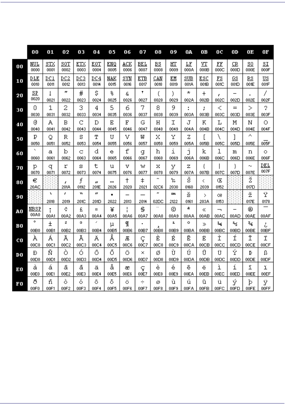
Microsoft Windows Codepage 1252 ................................................................................................................................................................... 310
Index ..................................................................................................................... 311
ASCII Chart ..................................................................................................................................................................................................................... 313
Product Reference Guide 1
Chapter 1
Introduction
About this Guide
This Product Reference Guide (PRG) is provided for users seeking advanced technical
information, including connection, programming, maintenance and specifications. The
Quick Reference Guide (QRG) and other publications associated with this product are
downloadable free of charge from the website listed on the back cover of this manual.
Typically, units are factory-programmed for the most common terminal and communi-
cations settings. If you need to modify any programmable settings, custom configuration
can be accomplished by scanning the programming bar codes within this guide.
Programming can alternatively be performed using the Datalogic Aladdin™ Configura-
tion application which is downloadable from the Datalogic website listed on the back
cover of this manual. This multi-platform utility program allows device configuration us-
ing a PC. It communicates to the device using a serial or USB cable and can also create
configuration bar codes to print.
Manual Overview
Chapter 1, Introduction provides a product overview, unpacking instructions, and cable
connection information.
Chapter 2, Getting Started presents information about unpacking and setting up the
reader.
Chapter 3, Interfaces consists of interface configuration bar codes and details.
Chapter 4, General Features includes programming bar codes for selecting common
features for the reader and general use bar codes to customize how the data is transmitted
to the host device.
Chapter 5, RS-232 ONLY Interface supplies information about setting up the reader for
RS-232 operation.
Chapter 6, RS-232/USB-Com Interfaces features information about options involving
both the RS-232 and USB-Com interfaces.
Chapter 7, Keyboard Interface discusses how to set up the reader for Keyboard Wedge
operation.
Chapter 8, USB-OEM Interface explains how to set the reader up for USB operation.
Chapter 9, Data Editing offers advanced configuration options for customization of
scanned data output.
Chapter 10, Symbologies defines options for all symbologies and provides the program-
Introduction
2 QuickScan
TM
Lite QW2100
ming bar codes necessary for configuring these features.
Chapter 11, References provides details concerning programmable features.
Appendix A, Technical Specifications lists physical and performance characteristics, as
well as environmental and regulatory specifications. It also provides standard cable pin-
outs.
Appendix B, Standard Defaults references common factory default settings for reader
features and options.
Appendix C, LED and Beeper Indications supplies tables containing descriptions of the
functions and behaviors of the reader’s LED and Beeper indicators.
Appendix D, Sample Bar Codes offers sample bar codes of several common symbolo-
gies.
Appendix E, Keypad includes numeric bar codes to be scanned for certain parameter set-
tings.
Appendix F, Scancode Tables lists control character emulation information for Wedge
and USB Keyboard interfaces.
Manual Conventions
The following conventions are used in this document:
The symbols listed below are used in this manual to notify the reader of key issues or
procedures that must be observed when using the reader:
References
Current versions of the Product Reference Guide (PRG), Quick Reference Guide
(QRG), the Datalogic Aladdin™ Configuration application, software/firmware and any
additional manuals, instruction sheets and utilities for this product can be downloaded
from the website listed on the back cover of this manual. Alternatively, printed copies or
product support CDs can be purchased through your Datalogic reseller.
NOTE
Notes contain information necessary for properly diagnosing, repair-
ing and operating the reader.
CAUTION
The CAUTION symbol advises you of actions that could damage
equipment or property.
Technical Support
Product Reference Guide
3
Technical Support
Datalogic Website Support
The Datalogic website (www.datalogic.com) is the complete source for technical support
and information for Datalogic products. The site offers product support, warranty infor-
mation, product manuals, product tech notes, software updates, demos, and instructions
for returning products for repair.
Reseller Technical Support
An excellent source for technical assistance and information is an authorized Datalogic
reseller. A reseller is acquainted with specific types of businesses, application software,
and computer systems and can provide individualized assistance.
Telephone Technical Support
If you do not have internet or email access, you may contact Datalogic technical support
at (541) 349-8283 or check the back cover of your manual for more contact information.
Introduction
4 QuickScan
TM
Lite QW2100
NOTES
Product Reference Guide 5
Chapter 2
Getting Started
About the Reader
One distinctive feature offered by the reader is a very wide scan angle which can read long
linearbar codes, such as utlity bills. Whether used in Single Trigger or Continuous Mode,
the ergonomic design of the reader will help to promote comfortable handling during ex-
tended periods of use.
The reader can communicate using the following interfaces:
RS-232 —
The reader can communicate with a standard or Wincor-Nixdorf (W-N) RS-
232 host.
RS-232 OPOS —
This interface is used for OPOS/UPOS/JavaPOS systems.
Keyboard Wedge (KBW)
When connected using this interface, the host interprets
scanned data as keystrokes and supports several international keyboards (for the Win-
dows
®
environment). See Country Mode on page 54 for a full listing.
USB —
Select to communicate either by USB OEM, USB COM STD, or USB Key-
board interface types by scanning the appropriate interface type bar codes available in this
manual. The default interface is USB-KBD for Wedge models (7230) and USB-OEM
for IBM models (7210).
Unpacking
Check carefully to ensure the reader and any accessories ordered are present and undam-
aged. If any damage occurred during shipment, contact
Technical Support on page 3.
KEEP THE PACKAGING. Should the unit ever require service, it should be returned
in its original shipping container.
Getting Started
6 QuickScan
TM
Lite QW2100
Setting Up the Reader
Follow the steps provided in this section to connect and get your reader up and commu-
nicating with its host:
1. Install the Interface Cable
2. Select the Interface Type
3. Configure Interface Settings (only if not using factory settings for that interface)
4. Configure Other Features (if modifications are needed from factory settings)
Install the Interface Cable
The reader kit you ordered to match your interface should provide a compatible cable for
your installation. If not, contact Technical Support.
Seat the cable assembly into the reader, aligning both the connector, aligning the cable
clip with its opening as shown in the insert portion of Figure 1.
RS-232 Serial Connection —
Turn off power to the terminal/PC and connect the
reader to the terminal/PC serial port via the RS-232 cable as shown in Figure 1. If the
terminal will not support POT (Power Off the Terminal) to supply reader power, use the
approved power supply (AC Adapter). Plug the AC Adapter barrel connector into the
socket on the RS-232 cable connector and the AC Adapter plug into a standard power
outlet.
Figure 1. Connecting the Interface Cable/RS-232 Connection
Other connection types are described below and illustrated in Figure 2.
Cable Clip (Latch)
To Host
Cable
Connecting at
the Reader
Disconnecting at
the Reader
Cable Strain Relief
Bottom of Imager
Interface Cable Port
Insert a paperclip
into this hole to
release the
cable latch
Strain Relief
Cable
Setting Up the Reader
Product Reference Guide
7
USB Connection —
Connect the reader to a USB port on the terminal/PC using the
correct USB cable for the interface type you ordered. Reference Figure 2.
Keyboard Wedge Connection —
The Keyboard Wedge cable has a ‘Y’ connection
from the reader. Connect the female to the male end from the keyboard and the remain-
ing end at the keyboard port at the terminal/PC. Reference Figure 2.
Figure 2. Other Interface Connections
Hands Free Stand
An accessory is available which holds the reader at a convenient angle, allowing hands
free scanning of items. Press in on the release buttons on both sides of the stand to raise
the arm of the stand as shown in
Figure 4. The stand can optionally be attached to a
counter or table using self-tapping screws or double-sided tape.
Figure 3. Adjusting the Stand Arm
NOTE
Specific cables are required for connection to different hosts. The
connectors illustrated above are examples only. Actual connectors
may vary from those illustrated, but the steps to connect the reader
remain the same.
U
S
B
I
B
M
K
e
y
b
o
a
r
d
W
e
d
g
e
or...
or...
Optional
abc
Getting Started
8 QuickScan
TM
Lite QW2100
Hands Free Stand — continued
The holder cup can be positioned in any of the three angles shown in Figure 4. Grasp
the holder cup as indicated and rotate to the desired position.
Refer to Scan Mode on page 30 for information about programming the reader for use
with the stand.
Figure 4. Adjusting the Stand
This accessory can also be used as a holder to mount the reader on a wall or other vertical
position as shown in Figure 5.
Figure 5. Using the Wall Holder
Programming
The reader is typically factory-configured with a set of default features standard to the
interface type you ordered. After scanning the interface bar code from the
Interfaces sec-
tion, you can select other options and customize your reader through use of the instruc-
tions and programming bar codes available in the corresponding features section for your
interface and also the
Data Editing and Symbologies chapters of this manual.
Setting Up the Reader
Product Reference Guide
9
Using the Programming Bar Codes
This manual contains feature descriptions and bar codes which allow you to reconfigure
your reader. Some programming bar code labels, like Resetting the Product Configura-
tion to Defaults on page 10
, require only the scan of that single label to enact the change.
Most of the programming labels in this manual, however, require the reader to be placed
in Programming Mode prior to scanning them. Scan an ENTER/EXIT bar code once to
enter Programming Mode. Once the reader is in Programming Mode, you can scan a
number of parameter settings before scanning the ENTER/EXIT bar code a second time,
which will then accept your changes, exit Programming Mode and return the reader to
normal operation.
Select the Interface Type
Upon completing the physical connection between the reader and its host, proceed di-
rectly to Interfaces on page 11 for information and programming for the interface type
the reader is connected to (for example: RS-232, Keyboard Wedge, USB, etc.) and scan
the appropriate bar code in that section to select your system’s correct interface type.
Configure Interface Settings
The reader is typically factory-configured with a set of default features standard to the
interface type you ordered. If after scanning the interface bar code from the Interfaces
section, your installation requires you to select options to further customize your reader,
turn to the appropriate section for your interface type as listed below:
RS-232 ONLY Interface, starting on page 37
RS-232/USB-Com Interfaces, starting on page 43
Keyboard Interface, starting on page 53
USB-OEM Interface, starting on page 65
Configure Other Features
If your installation requires different programming than the standard factory default set-
tings, the following sections of this manual allow configuration of non-interface-specific
settings you might require:
General Features
General Features includes programming for scanning, beeper and
LED indicators and other such universal settings.
Symbologies
Includes options concerning the bar code label types (symbologies).
These settings allow you to enable/disable symbologies, set label lengths, require check
digit, etc.
NOTE
There are some exceptions to the typical programming sequence
described above. Please read the description and setting instruc-
tions carefully when configuring each given programmable feature.
Getting Started
10 QuickScan
TM
Lite QW2100
Software Version Transmission
The software version of the device can be transmitted over the RS-232 and Keyboard in-
terfaces by scanning the following label.
Resetting the Product Configuration to Defaults
If you aren't sure what programming options are in your reader, or you've changed some
options and want to restore the Custom Default Configuration that may have been saved
in the reader, scan the Restore Custom Default Configuration bar code below. This will
restore the custom configuration for the currently active interface.
Resetting the Product Configuration to Defaults — cont.
If you aren't sure what programming options are in your reader, or you've changed some
options and want to restore the Factory Configuration, you have two options. You can
scan the Restore USA Factory Configuration bar code or the Restore EU Factory Con-
figuration
bar code below. Both labels restore the reader configuration to the factory set-
tings including the interface type. The USA label restores Label IDs to those historically
used in the USA. The EU label restores Label IDs to those historically used in Europe.
The Label ID sets for USA and EU are shown in the Label ID section of this manual.
The programming section lists the factory default settings for each of the menu com-
mands (indicated by shaded blocks and bold text) on the following pages.
NOTE
Custom defaults are based on the interface type. Configure the
reader for the correct interface before scanning this label.
Product Reference Guide 11
Chapter 3
Interfaces
Interface Selection
Each reader model will support one of the following sets of host interfaces:
USB Models (all are 2.0 full speed)
USB KBD
USB COM STD
USB OEM
RS-232 / Keyboard Wedge Models
RS-232 (Standard, Wincor-Nixdorf, OPOS)
Keyboard Wedge
Configuring the Interface
Scan the programming bar code from this section which selects the appropriate interface type
matching the system the reader will be connected to. Next, proceed to the corresponding chap-
ter in this manual (also listed in Ta bl e 1 ) to configure any desired settings and features associ-
ated with that interface.
NOTE
Unlike some other programming features and options, interface
selections require that you scan only one programming bar code
label. DO NOT scan an ENTER/EXIT bar code prior to scanning an
interface selection bar code.
Some interfaces require the reader to start in the disabled state when
powered up. If additional reader configuration is desired while in this
state, pull the trigger and hold it for five seconds. The reader will
change to a state that allows programming with bar codes.
Interfaces
12
QuickScan
TM
Lite QW2100
Table 1. Available Interfaces
RS-232 FEATURES
RS-232 standard interface
$P,HA05,P
Select RS232-STD
Set RS-232
Interface
Features
starting on
page 37
$P,HA12,P
Select RS232-WN
RS-232 Wincor-Nixdorf
RS-232 for use with OPOS/UPOS/JavaPOS
$P,HA13,P
Select RS-232 OPOS
$P,HA13,P
Select USB-COM-STD
a
USB Com to simulate RS-232 standard interface
USB-OEM FEATURES
USB-OEM
(can be used for OPOS/UPOS/JavaPOS)
$P,HA45,P
Select USB-OEM
Set USB-OEM
Interface
Features
starting on
page 65
a.
Download the correct USB Com driver from www.datalogic.com
Configuring the Interface
Product Reference Guide
13
KEYBOARD FEATURES
AT, PS/2 25-286, 30-286, 50, 50Z, 60, 70, 80, 90 & 95
w/Standard Key Encoding
$P,HA29,P
Select KBD-AT
Set KEYBOARD
WEDGE
Interface
Features
starting on page
53
$P,HA11,P
Select KBD-AT-NK
Keyboard Wedge for IBM AT PS2 with standard key
encoding but without external keyboard
AT, PS/2 25-286, 30-286, 50, 50Z, 60, 70, 80, 90 & 95
w/Alternate Key
$P,HA26,P
Select KBD-AT-ALT
$P,HA10,P
Select KBD-AT-ALT-NK
Keyboard Wedge for IBM AT PS2 with alternate key
encoding but without external keyboard
PC/XT w/Standard Key Encoding
$P,HA28,P
Select KBD-XT
Interfaces
14
QuickScan
TM
Lite QW2100
KEYBOARD — cont. FEATURES
USB Keyboard with standard key encoding
$P,HA35,P
Select USB Keyboard
Set KEYBOARD
WEDGE
Interface
Features
starting on page
53
$P,HA2B,P
Select USB Alternate Keyboard
USB Keyboard with alternate key encoding
Global Interface Features
Product Reference Guide 15
ENTER/EXIT PROGRAMMING MODE
Global Interface Features
The following interface features are configurable by all interface types. To set features specific to
your interface, turn to that section of this manual:
RS-232 ONLY Interface on page 37
RS-232/USB-Com Interfaces on page 43
Keyboard Interface on page 53
USB-OEM Interface on page 65
Host Commands — Obey/Ignore
This option specifies whether the reader will obey or ignore host commands. When set to
ignore, the reader will ignore all host commands except for those necessary for:
•service mode
flash programming mode
keeping the interface active
transmission of labels.
$CIFIH00
Host Commands = Obey
$CIFIH01
Host Commands = Ignore
DEFAULT
Interfaces
16
QuickScan
TM
Lite QW2100
ENTER/EXIT PROGRAMMING MODE
USB Suspend Mode
This setting enables/disables the ability of USB interfaces to enter suspend mode.
$CUSSE00
USB Suspend Mode = Disable
$CUSSE01
USB Suspend Mode = Enable
DEFAULT
Product Reference Guide 17
Chapter 4
General Features
Double Read Timeout
To prevent a double read of the same label, the Double Read Timeout sets the minimum time
allowed between reads of labels of the same symbology and data. If the unit reads a label and sees
the same label again within the Double Read Timeout, the second read of the label will be
ignored. Double Read Timeout does not apply to scan modes that require a trigger pull for each
label that is read.
ENTER/EXIT PROGRAMMING MODE
$CSNDR0A
Double Read Timeout = 0.1 Second
$CSNDR14
Double Read Timeout = 0.2 Second
$CSNDR1E
Double Read Timeout = 0.3 Second
$CSNDR28
Double Read Timeout = 0.4 Second
DEFAULT
General Features
18
QuickScan
TM
Lite QW2100
ENTER/EXIT PROGRAMMING MODE
Double Read Timeout — continued
$CSNDR32
Double Read Timeout = 0.5 Second
$CSNDR3C
Double Read Timeout = 0.6 Second
$CSNDR46
Double Read Timeout = 0.7 Second
$CSNDR50
Double Read Timeout = 0.8 Second
$CSNDR5A
Double Read Timeout = 0.9 Second
$CSNDR64
Double Read Timeout = 1 Second
Label Gone Timeout
Product Reference Guide 19
ENTER/EXIT PROGRAMMING MODE
Label Gone Timeout
This feature sets the time after the last label segment is seen before the reader prepares for a new
label. The timeout can be set within a range of 10 milliseconds to 2,550 milliseconds (2.55 sec-
onds) in 10ms increments. Label Gone Timeout does not apply to scan modes that require a
trigger pull for each label that is read. See Label Gone Timeout on page 244 for more detailed pro-
gramming instructions.
$CSNLG
Select Label Gone Timeout Setting
Make a mistake? Scan the CANCEL bar code to abort and not
save the entry string. You can then start again at the beginning.
~
CANCEL
DEFAULT
016 = Timeout of 160 ms
General Features
20
QuickScan
TM
Lite QW2100
ENTER/EXIT PROGRAMMING MODE
Power Save Mode
When this feature is enabled, the reader will enter Power Save Mode (a lower power
consumption state) after being idle (no scanner activity) for one second.
NOTE
RS-232 and USB interfaces ONLY.
A reader having a Scan Mode setting of Object Sense, Stand Mode,
Flashing, or Always On will not enter Power Save Mode. (The reader
is always internally active when in these modes.)
$CSLEN00
Power Save Mode = Disabled
$CSLEN01
Power Save Mode = Enabled
DEFAULT
Sleep Mode Timeout
Product Reference Guide 21
ENTER/EXIT PROGRAMMING MODE
Sleep Mode Timeout
Specifies the timeout value for the reader to enter Sleep Mode (a very low power consumption
state).
NOTE
RS-232 interface ONLY.
A reader having a Scan Mode setting of Object Sense, Stand Mode,
Flashing, or Always On will not enter Sleep Mode. (The reader is
always internally active when in these modes.)
$CSLTO00
Sleep Mode Timeout = Disabled
$CSLTO1E
Sleep Mode Timeout = 30 Seconds
$CSLTO3C
Sleep Mode Timeout = 1 Minute (60 Seconds)
$CSLTO5A
Sleep Mode Timeout = 1 Minute 30 Seconds (90 Seconds)
$CSLTO78
Sleep Mode Timeout = 2 Minutes (120 Seconds)
DEFAULT
General Features
22
QuickScan
TM
Lite QW2100
ENTER/EXIT PROGRAMMING MODE
LED and Beeper Indicators
Power On Alert
Disables or enables the indication (from the Beeper) that the reader is receiving power.
$CBPPU00
Power On Alert = Disable (No Audible Indication)
$CBPPU01
Power On Alert = Power-up Beep
DEFAULT
LED and Beeper Indicators
Product Reference Guide 23
ENTER/EXIT PROGRAMMING MODE
Good Read: When to Indicate
This feature specifies when the reader will provide indication (beep and/or flash its green LED)
upon successfully reading a bar code. Choices are:
Good Read = Indicate after decode
Good Read = Indicate after transmit
Good Read = Indicate after CTS goes inactive, then active
NOTE
This option, which uses CTS, is only valid for RS-232
interfaces.
$CBPIN00
Indicate Good Read = After Decode
$CBPIN01
Indicate Good Read = After Transmit
$CBPIN02
Indicate Good Read = After CTS Goes Inactive, Then Active
DEFAULT
$CBPIN00
General Features
24
QuickScan
TM
Lite QW2100
ENTER/EXIT PROGRAMMING MODE
Good Read Beep Type
Specifies whether the good read beep has a mono or bitonal beep sound.
$CBPTY00
Good Read Beep Type = Mono
$CBPTY01
Good Read Beep Type = Bitonal
DEFAULT
LED and Beeper Indicators
Product Reference Guide 25
ENTER/EXIT PROGRAMMING MODE
Good Read Beep Frequency
Adjusts the good read beep to sound at a selectable low, medium or high frequency, selectable
from the list below. (Controls the beeper’s pitch/tone.)
Good Read Beep Length
Specifies the duration of a good read beep.
$CBPFR00
Good Read Beep Frequency = Low
$CBPFR01
Good Read Beep Frequency = Medium
$CBPFR02
Good Read Beep Frequency = High
DEFAULT
$CBPLE06
Good Read Beep Length = 60 msec
General Features
26
QuickScan
TM
Lite QW2100
ENTER/EXIT PROGRAMMING MODE
Good Read Beep Length — continued
$CBPLE08
Good Read Beep Length = 80 msec
$CBPLE0A
Good Read Beep Length = 100 msec
$CBPLE0C
Good Read Beep Length = 120 msec
$CBPLE0E
Good Read Beep Length = 140 msec
$CBPLE10
Good Read Beep Length = 160 msec
$CBPLE12
Good Read Beep Length = 180 msec
$CBPLE14
Good Read Beep Length = 200 msec
DEFAULT
LED and Beeper Indicators
Product Reference Guide 27
ENTER/EXIT PROGRAMMING MODE
Illumination Control
Controls illumination during a good read beep.
NOTE
Setting this configuration item to turn off illumination
during the beep reduces the peak current drawn by the
reader in some scanning modes.
$CBPIC00
Illumination Control = Illumination off during beep
$CBPIC01
Illumination Control = Illumination and beep are
independently controlled
DEFAULT
$
General Features
28
QuickScan
TM
Lite QW2100
ENTER/EXIT PROGRAMMING MODE
Good Read Beep Volume
Selects the beeper volume (loudness) upon a good read beep. There are three selectable volume
levels.
$CBPVO00
Good Read Beep Volume = Beeper Off
$CBPVO01
Good Read Beep Volume = Low
$CBPVO02
Good Read Beep Volume = Medium
$CBPVO03
Good Read Beep Volume = High
DEFAULT
LED and Beeper Indicators
Product Reference Guide 29
ENTER/EXIT PROGRAMMING MODE
Good Read LED Duration
This feature specifies the amount of time that the Good Read LED remains on following a good
read. The good read LED on time can be set within a range of 0.1 to 25.5 seconds in 100ms
increments. See Good Read LED Duration on page 245 for more detailed programming instruc-
tions.
$CLAGL
Select Good Read LED Duration Setting
Make a mistake? Scan the CANCEL bar code to abort and not
save the entry string. You can then start again at the beginning.
~
CANCEL
DEFAULT
020 = Good Read LED stays on for 2
seconds.
NOTE
Indicators are dimmed during sleep.
General Features
30
QuickScan
TM
Lite QW2100
ENTER/EXIT PROGRAMMING MODE
Scanning Features
Scan Mode
See Scan Mode on page 246 for more detailed programming instructions.
$CSNRM00
Scan Mode = Trigger Single
$CSNRM01
Scan Mode = Trigger Hold Multiple
$CSNRM02
Scan Mode = Trigger Pulse Multiple
$CSNRM03
Scan Mode = Flashing
$CSNRM04
Scan Mode = Always On
$CSNRM05
Scan Mode = Autosense
®
Stand Mode
$CSNRM06
Scan Mode = Trigger Object Sense
DEFAULT
Scanning Features
Product Reference Guide 31
ENTER/EXIT PROGRAMMING MODE
Stand Mode Triggered Timeout
This feature specifies the time to remain in Trigger Single mode after the trigger is pulled while in
Autosense® Stand Mode.
NOTE
This timeout is only used when the Scan Mode is configured as
Autosense®
Stand Mode
.
$CSNOT01
Stand Mode Triggered Timeout = 0.5 Seconds
$CSNOT03
Stand Mode Triggered Timeout = 1.5 Seconds
$CSNOT04
Stand Mode Triggered Timeout = 2 Seconds
$CSNOT06
Stand Mode Triggered Timeout = 3 Seconds
$CSNOT08
Stand Mode Triggered Timeout = 4 Seconds
DEFAULT
General Features
32
QuickScan
TM
Lite QW2100
ENTER/EXIT PROGRAMMING MODE
Stand Mode Triggered Timeout — continued
$CSNOT0C
Stand Mode Triggered Timeout = 6 Seconds
$CSNOT10
Stand Mode Triggered Timeout = 8 Seconds
$CSNOT00
Stand Mode Triggered Timeout = Switch back to Trigger Single
on trigger pull
Scanning Features
Product Reference Guide 33
ENTER/EXIT PROGRAMMING MODE
Scanning Active Time
This setting specifies the amount of time that the reader stays in scan ON state once the state is
entered. The range for this setting is from 1 to 255 seconds in 1-second increments. See Scan-
ning Active Time on page 247 for more detailed programming instructions.
Stand Mode Flash
Enables/disables the LED flash when the reader is in Stand Mode.
$CSNET
Select Scanning Active Time Setting
Make a mistake? Scan the CANCEL bar code to abort and not
save the entry string. You can then start again at the beginning.
~
CANCEL
DEFAULT
005 = Scanning is active for 5 Seconds
$CSMFL00
Stand Mode Flash = Disable
$CSMFL01
Stand Mode Flash = Enable
DEFAULT
General Features
34
QuickScan
TM
Lite QW2100
ENTER/EXIT PROGRAMMING MODE
Flash On Time
This feature specifies the ON time for the indicator LED while in Flash Mode. The selectable
range is 100 to 9,900 milliseconds (0.1 to 9.9 seconds), in 100 millisecond increments. See
Flash On Time on page 248 for more detailed programming instructions.
Flash Off Time
This feature specifies the OFF time for the indicator LED while in Flash Mode. The selectable
range is 100 to 9,900 milliseconds (0.1 to 9.9 seconds), in 100 millisecond increments. See
Flash Off Time on page 249 for more detailed programming instructions.
$CSNFN
Select Flash ON Time Setting
Make a mistake? Scan the CANCEL bar code to abort and not
save the entry string. You can then start again at the beginning.
~
CANCEL
DEFAULT
10 = Flash is ON for 1 Second
$CSNFF
Select Flash OFF Time Setting
Make a mistake? Scan the CANCEL bar code to abort and not
save the entry string. You can then start again at the beginning.
~
CANCEL
Scanning Features
Product Reference Guide 35
ENTER/EXIT PROGRAMMING MODE
Stand Mode Sensitivity
Sets the sensitivity level for stand mode wakeup. Choices are low, medium and high.
DEFAULT
06 = Flash is OFF for 600ms
$CSMSE00
Stand Mode Sensitivity = Low
$CSMSE01
Stand Mode Sensitivity = Medium
$CSMSE02
Stand Mode Sensitivity = High
DEFAULT
General Features
36
QuickScan
TM
Lite QW2100
ENTER/EXIT PROGRAMMING MODE
Green Spot Duration
Specifies the duration of the good read pointer beam after a good read.
$CLSSP00
Green Spot Duration = Disable (Green Spot is Off)
$CLSSP01
Green Spot Duration = Short (300 msec)
$CLSSP02
Green Spot Duration = Medium (500 msec)
$CLSSP03
Green Spot Duration = Long (800 msec)
DEFAULT
Product Reference Guide 37
Chapter 5
RS-232 ONLY Interface
Introduction
Use the programming bar codes in this chapter if modifications to the standard RS-232 inter-
face settings are necessary to meet your systems requirements. Additional settings which apply
to both the RS-232 and USB interfaces are available in Chapter 6, RS-232/USB-Com Inter-
faces.
RS-232 Standard Factory Settings
Reference Appendix B, Standard Defaults for a listing of standard factory settings.
Baud Rate
Baud rate is the number of bits of data transmitted per second. Set the reader's baud rate to
match the baud rate setting of the host device. With an improper baud rate setting, data may
not reach the host correctly.
ENTER/EXIT PROGRAMMING MODE
$CR2BA00
Baud Rate = 1200
$CR2BA01
Baud Rate = 2400
$CR2BA02
Baud Rate = 4800
RS-232 ONLY Interface
38
QuickScan
TM
Lite QW2100
ENTER/EXIT PROGRAMMING MODE
Baud Rate — continued
$CR2BA03
Baud Rate = 9600
$CR2BA04
Baud Rate = 19,200
$CR2BA05
Baud Rate = 38,400
$CR2BA06
Baud Rate = 57,600
$CR2BA07
Baud Rate = 115,200
DEFAULT
Data Bits
Product Reference Guide 39
ENTER/EXIT PROGRAMMING MODE
Data Bits
This parameter allows the reader to interface with devices requiring a 7-bit or 8-bit ASCII pro-
tocol for sending and receiving data.
Stop Bits
The stop bit(s) at the end of each transmitted character marks the end of transmission of one
character and prepares the receiving device for the next character in the serial data stream. The
number of stop bits selected (one or two) depends on the number the receiving terminal is pro-
grammed to accommodate. Set the number of stop bits to match host device requirements.
$CR2DA00
7 Data Bits
$CR2DA01
8 Data Bits
DEFAULT
$CR2ST00
1 Stop Bit
$CR2ST01
2 Stop Bits
DEFAULT
RS-232 ONLY Interface
40
QuickScan
TM
Lite QW2100
ENTER/EXIT PROGRAMMING MODE
Parity
This feature specifies parity required for sending and receiving data. A parity check bit is the
most significant bit of each ASCII coded character. Select the parity type according to host
device requirements.
Select None when no parity bit is required.
Select Odd parity and the parity bit value is set to 0 or 1, based on data, to ensure that an
odd number of 1 bits are contained in the coded character.
Select Even parity and the parity bit value is set to 0 or 1, based on data, to ensure that an
even number of 1 bits are contained in the coded character.
$CR2PA00
Parity = None
$CR2PA01
Parity = Even
$CR2PA02
Parity = Odd
DEFAULT
Handshaking Control
Product Reference Guide 41
ENTER/EXIT PROGRAMMING MODE
Handshaking Control
The data interface consists of an RS-232 port designed to operate either with or without the
hardware handshaking lines, Request to Send (RTS), and Clear to Send (CTS). Handshaking
Control includes the following options:
RTS — RTS is asserted during transmissions. CTS is ignored.
RTS/CTS — RTS is asserted during transmissions. CTS gates transmissions.
RTS/XON/XOFF — RTS is asserted during transmissions. CTS is ignored. XON and
XOFF gate transmissions.
RTS On/CTS — RTS is always asserted. CTS gates transmissions.
RTS/CTS Scan Control — RTS is asserted during transmissions. CTS gates transmis-
sions and controls enable and disable state of reader.
$CR2HC00
Handshaking Control = RTS
$CR2HC01
Handshaking Control = RTS/CTS
$CR2HC02
Handshaking Control = RTS/XON/XOFF
$CR2HC03
Handshaking Control = RTS On/CTS
$CR2HC04
Handshaking Control = RTS/CTS Scan Control
DEFAULT
RS-232 ONLY Interface
42
QuickScan
TM
Lite QW2100
NOTES
Product Reference Guide 43
Chapter 6
RS-232/USB-Com Interfaces
Introduction
The programming bar codes in this chapter allow modifications to the standard RS-232 and
USB-Com interfaces.
Standard Factory Settings
Reference Appendix B, Standard Defaults for a listing of standard factory settings.
RS-232/USB-Com Interfaces
44
QuickScan
TM
Lite QW2100
ENTER/EXIT PROGRAMMING MODE
Intercharacter Delay
This parameter specifies the intercharacter delay between the end of one character and the
beginning of the next. The delay can be set within a range of zero (0) to 990 milliseconds in
10ms increments. A setting of zero specifies no delay. See Intercharacter Delay on page 250
for more detailed programming instructions.
$CR2IC00
Intercharacter Delay = No Delay
$CR2IC
Select Intercharacter Delay Setting
Make a mistake? Scan the CANCEL bar code to abort and not
save the entry string. You can then start again at the beginning.
~
CANCEL
DEFAULT
00 = No Intercharacter Delay
Beep On ASCII BEL
Product Reference Guide 45
ENTER/EXIT PROGRAMMING MODE
Beep On ASCII BEL
When this parameter is enabled, the reader issues a beep when a <BEL> character is detected on
the RS-232 serial line. <BEL> is issued to gain a user's attention to an illegal entry or other
important event.
Beep On Not on File
This option enables/disables the action of the reader to sound a three beep sequence upon
receiving a Not-On-File (NOF) host command.
$CR2BB00
Beep On ASCII BEL = Disable
$CR2BB01
Beep On ASCII BEL = Enable
DEFAULT
$CBPNF00
Beep On Not On File = Disable
$CBPNF01
Beep On Not On File = Enable
DEFAULT
RS-232/USB-Com Interfaces
46
QuickScan
TM
Lite QW2100
ENTER/EXIT PROGRAMMING MODE
ACK NAK Options
This enables/disables the ability of the reader to support the RS-232 ACK/NAK protocol.
When configured, the reader and/or host sends an “ACK” when it receives data properly, and
sends “NAK” when the data is in error.
Options are:
•Disable
Enable for label transmission — The reader expects an ACK/NAK response from the host
when a label is sent.
Enable for host-command acknowledge — The reader will respond with ACK/NAK
when the host sends a command.
Enable for label transmission and host-command acknowledge
$CR2AE00
ACK/NAK Protocol = Disable ACK/NAK
$CR2AE01
ACK/NAK Protocol = Enable for label transmission
$CR2AE02
ACK/NAK Protocol = Enable for host-command
acknowledge
$CR2AE03
ACK/NAK Protocol = Enable for label transmission and host-com-
mand acknowledge
DEFAULT
ACK NAK Options
Product Reference Guide 47
ENTER/EXIT PROGRAMMING MODE
ACK Character
This setting specifies an ASCII character or hex value to be used as the ACK character. ASCII
characters or any hex value from 0 to 0xFF can be selected. See ACK Character on page 251
for more detailed programming instructions.
NAK Character
This setting specifies an ASCII character or hex value to be used as the NAK character. ASCII
characters or any hex value from 0 to 0xFF can be selected. See NAK Character on page 252
for more detailed programming instructions.
NOTE
Setting to previously defined characters such as XON, XOFF, or host
commands conflicts with normal operation of these characters. 8-bit
data is not recognized when the option
Data Bits has been set as 7
Data Bits.
$CR2AC
Select ACK Character Setting
DEFAULT
0x06 ‘ACK’ Character
NOTE
Setting to previously defined characters such as XON, XOFF, or host
commands conflicts with normal operation of these characters. 8-bit
data is not recognized when the option
Data Bits has been set as 7
Data Bits.
$CR2NA
Select NAK Character Setting
DEFAULT
0x15 ‘NAK’ Character
RS-232/USB-Com Interfaces
48
QuickScan
TM
Lite QW2100
ENTER/EXIT PROGRAMMING MODE
ACK NAK Timeout Value
This option specifies the amount of time the reader waits for an ACK character from the host
following label transmission. The selectable timeout range is 200 milliseconds to 15,000ms (15
seconds) in 200ms increments. A selection of 0 disables the timeout. See ACK NAK Timeout
Value on page 253 for more detailed programming instructions.
$CR2AT
Select ACK NAK Timeout Value Setting
Make a mistake? Scan the CANCEL bar code to abort and not
save the entry string. You can then start again at the beginning.
~
CANCEL
DEFAULT
01 ACK NAK Timeout value is 200ms
ACK NAK Options
Product Reference Guide 49
ENTER/EXIT PROGRAMMING MODE
ACK NAK Retry Count
This feature specifies the number of times the reader retries a label transmission due to a retry
condition. The selectable range is from 1 to 254 retries. A selection of 0 disables the count, and
a selection of 255 specifies unlimited retries. See ACK NAK Retry Count on page 254 for
more detailed programming instructions.
$CR2AR
Select ACK NAK Retry Count Setting
Make a mistake? Scan the CANCEL bar code to abort and not
save the entry string. You can then start again at the beginning.
~
CANCEL
DEFAULT
003 = 3 Retries
RS-232/USB-Com Interfaces
50
QuickScan
TM
Lite QW2100
ENTER/EXIT PROGRAMMING MODE
ACK NAK Error Handling
This feature specifies the method the reader uses to handle receive errors detected while waiting
for an ACK character from the host.
Options are:
Ignore errors detected
Process error as valid ACK character
Process error as valid NAK character
$CR2EH00
ACK NAK Error Handling = Ignore Errors Detected
$CR2EH01
ACK NAK Error Handling = Process Error as Valid ACK Character
$CR2EH02
ACK NAK Error Handling = Process Error as
Valid NAK Character
DEFAULT
Indicate Transmission Failure
Product Reference Guide 51
ENTER/EXIT PROGRAMMING MODE
Indicate Transmission Failure
This option enables/disables the reader’s ability to sound an error beep to indicate a transmission
failure while in ACK/NAK mode.
Disable Character
Specifies the value of the RS-232 host command used to disable the reader.
ASCII characters or any hex value from 0 to 0xFF can be selected. See Disable Character on
page 255 for more detailed programming instructions.
$CR2TF00
Indicate Transmission Failure = Disable Indication
$CR2TF01
Indicate Transmission Failure = Enable Indication
DEFAULT
NOTE
Setting to previously defined characters such as XON, XOFF, or host
commands conflicts with normal operation of these characters. 8-bit
data is not recognized when the option
Data Bits has been set as 7
Data Bits.
$CR2DC
Select Disable Character Setting
DEFAULT
0x44 = Disable Character is ‘D’
RS-232/USB-Com Interfaces
52
QuickScan
TM
Lite QW2100
ENTER/EXIT PROGRAMMING MODE
Enable Character
Specifies the value of the RS-232 host command used to enable the reader.
ASCII characters or any hex value from 0 to 0xFF can be selected. See Enable Character on
page 256 for more detailed programming instructions.
NOTE
Setting to previously defined characters such as XON, XOFF, or host
commands conflicts with normal operation of these characters. 8-bit
data is not recognized when the option
Data Bits has been set as 7
Data Bits.
$CR2EC
Select Enable Character Setting
DEFAULT
0x45 = Enable Character is ‘E’
Product Reference Guide 53
Chapter 7
Keyboard Interface
Introduction
Use the programming bar codes in this chapter to select options for USB Keyboard and Wedge
Interfaces.
Standard Factory Settings
Reference Appendix B, Standard Defaults for a listing of standard factory settings.
Scancode Tables
Information about control character emulation which applies to keyboard interfaces is listed in
Appendix F, Scancode Tables.
Keyboard Interface
54
QuickScan
TM
Lite QW2100
ENTER/EXIT PROGRAMMING MODE
Country Mode
This feature specifies the country/language supported by the keyboard.
Only the following interfaces support ALL Country Modes.
USB Keyboard (without alternate key encoding)
Keyboard Wedge
All other interfaces support ONLY the following Country Modes: U.S., Belgium, Britain,
France, Germany, Italy, Spain, Sweden.
$CKBCO00
Country Mode = U.S.
$CKBCO01
Country Mode = Belgium
$CKBCO02
Country Mode = Britain
$CKBCO11
Country Mode = Croatia
Supports only the interfaces listed in the Country Mode feature
description.
Supports only the interfaces listed in the Country Mode feature
description.
$CKBCO0E
Country Mode = Czechoslovakia
DEFAULT
Country Mode
Product Reference Guide 55
ENTER/EXIT PROGRAMMING MODE
Country Mode — continued
$CKBCO03
Country Mode = Denmark
Supports only the interfaces listed in the Country Mode feature
description.
$CKBCO04
Country Mode = France
$CKBCO05
Country Mode = Germany
Supports only the interfaces listed in the Country Mode feature
description.
$CKBCO0D
Country Mode = Hungary
$CKBCO06
Country Mode = Italy
Supports only the interfaces listed in the Country Mode feature
description.
$CKBCO0C
Country Mode = Japanese 106-key
$CKBCO07
Country Mode = Norway
Supports only the interfaces listed in the Country Mode feature
description.
Keyboard Interface
56
QuickScan
TM
Lite QW2100
ENTER/EXIT PROGRAMMING MODE
Country Mode — continued
$CKBCO12
Country Mode = Poland
Supports only the interfaces listed in the Country Mode feature
description.
Supports only the interfaces listed in the Country Mode feature
description.
$CKBCO08
Country Mode = Portugal
$CKBCO10
Country Mode = Romania
Supports only the interfaces listed in the Country Mode feature
description.
Supports only the interfaces listed in the Country Mode feature
description.
$CKBCO0F
Country Mode = Slovakia
$CKBCO09
Country Mode = Spain
$CKBCO0A
Country Mode = Sweden
$CKBCO0B
Country Mode = Switzerland
Supports only the interfaces listed in the Country Mode feature
description.
Caps Lock State
Product Reference Guide 57
ENTER/EXIT PROGRAMMING MODE
Caps Lock State
This option specifies the format in which the reader sends character data. This applies to Key-
board Wedge interfaces.
This does not apply when an alternate key encoding keyboard is selected.
Numlock
This option specifies the setting of the Numbers Lock (Numlock) key while in Keyboard Wedge
interface. This only applies to alternate key encoding interfaces.
It does not apply to USB Keyboard.
$CKBCL00
Caps Lock State = Caps Lock OFF
$CKBCL01
Caps Lock State = Caps Lock ON
$CKBCL02
Caps Lock State = AUTO Caps Lock Enable
DEFAULT
$CKBNL00
Numlock = Numlock key unchanged
$CKBNL01
Numlock = Numlock key toggled
DEFAULT
Keyboard Interface
58
QuickScan
TM
Lite QW2100
ENTER/EXIT PROGRAMMING MODE
Keyboard Numeric Keypad
This feature specifies if numeric characters will be sent using the standard keys or the numeric
keypad
.
$CKBKP00
Keyboard Numeric Keypad = Standard Keys
$CKBKP01
Keyboard Numeric Keypad = Numeric Keypad
DEFAULT
Keyboard Send Control Characters
Product Reference Guide 59
ENTER/EXIT PROGRAMMING MODE
Keyboard Send Control Characters
This feature is used by the Keyboard Wedge and USB Keyboard interfaces. It specifies how the
reader transmits ASCII control characters to the host. Reference Appendix F, Scancode
Ta bles for more information about control characters.
Options are as follows:
Send Ctrl+Key —
ASCII characters from 00H to 0x1FH inclusive are transmitted in the for-
mat Ctrl+Key. Special keys are available in the range from 81H to A1.
Send Ctrl+Shift+Key —
The behavior is the same as above, but control keys are sent in the
format Ctrl+Shift+Keys.
Send Special Function Key —
Send characters between 00H and 1FH according to the spe-
cial function key mapping table (see Microsoft Windows Codepage 1252 on page 310).
This is used to send keys that are not in the normal ASCII set. A unique set is provided for each
available scancode set.
$CKBSC00
Keyboard Send Control Characters = 00
$CKBSC01
Keyboard Send Control Characters = 01
$CKBSC02
Keyboard Send Control Characters = 02
DEFAULT
Keyboard Interface
60
QuickScan
TM
Lite QW2100
ENTER/EXIT PROGRAMMING MODE
Wedge Quiet Interval
This option specifies the amount of time to look for keyboard activity before the reader
breaks the keyboard connection in order to transmit data to host. The selectable range for
this feature is from 0 to 990ms in 10ms increments. See Wedge Quiet Interval on
page 257 for more detailed programming instructions.
NOTE
This feature applies ONLY to the Keyboard Wedge interface.
$CKBQI
Select Wedge Quiet Interval Setting
Make a mistake? Scan the CANCEL bar code to abort and not
save the entry string. You can then start again at the beginning.
~
CANCEL
DEFAULT
10 = Quiet Interval of 100 ms
Intercharacter Delay
Product Reference Guide 61
ENTER/EXIT PROGRAMMING MODE
Intercharacter Delay
This parameter specifies the intercharacter delay between the end of one character and the
beginning of the next. The delay can be set within a range of zero (0) to 990 milliseconds in
10ms increments. A setting of zero specifies no delay. See Intercharacter Delay on
page 258 for more detailed programming instructions.
NOTE
This feature applies ONLY to the Keyboard Wedge interface.
$CR21C00
Intercharacter Delay = No Delay
$CR21C
Select Intercharacter Delay Setting
Make a mistake? Scan the CANCEL bar code to abort and not
save the entry string. You can then start again at the beginning.
~
CANCEL
DEFAULT
00 = No Intercharacter Delay
Keyboard Interface
62
QuickScan
TM
Lite QW2100
ENTER/EXIT PROGRAMMING MODE
Intercode Delay
Specifies the delay between labels transmitted to the host for this interface. The selectable range
for this feature is from 0 to 99 seconds. See Intercode Delay on page 259 for more detailed
programming instructions.
$CKBID
Set Intercode Delay
Make a mistake? Scan the CANCEL bar code to abort and not
save the entry string. You can then start again at the beginning.
~
CANCEL
DEFAULT
00 = No Wedge Intercode Delay
USB Keyboard Speed
Product Reference Guide 63
ENTER/EXIT PROGRAMMING MODE
USB Keyboard Speed
This option specifies the USB poll rate for a USB Keyboard.
NOTE
This feature applies ONLY to the USB Keyboard interface.
$CKBSP01
USB Keyboard Speed = 1ms
$CKBSP02
USB Keyboard Speed = 2ms
$CKBSP03
USB Keyboard Speed = 3ms
$CKBSP04
USB Keyboard Speed = 4ms
$CKBSP05
USB Keyboard Speed = 5ms
DEFAULT
Keyboard Interface
64
QuickScan
TM
Lite QW2100
ENTER/EXIT PROGRAMMING MODE
USB Keyboard Speed — continued
$CKBSP06
USB Keyboard Speed = 6ms
$CKBSP07
USB Keyboard Speed = 7ms
$CKBSP08
USB Keyboard Speed = 8ms
$CKBSP09
USB Keyboard Speed = 9ms
$CKBSP0A
USB Keyboard Speed = 10ms
Product Reference Guide 65
Chapter 8
USB-OEM Interface
Introduction
Feature settings for USB interfaces differ depending upon which host type the reader will be
connected with. Use the feature settings in this chapter to specifically configure for the USB-
OEM interface. Other USB interfaces are included in the approprite chapter for their host type.
Standard Factory Settings
Reference Appendix B, Standard Defaults for a listing of standard factory settings.
USB-OEM Interface
66
QuickScan
TM
Lite QW2100
ENTER/EXIT PROGRAMMING MODE
USB-OEM Device Usage
The USB-OEM protocol allows for the reader to be identified as one of two different types of
bar code readers. Depending on what other scanners you may already have connected to a USB-
OEM POS, you may need to change this setting to enable all devices to communicate.
Options are:
Table Top Scanner
Handheld Scanner
USB-OEM Interface Options
This setting provides for an interface specific control mechanism..
Options are:
Obey — Obey Reader Configuration Host Commands
Ignore — Ignore Reader Configuration Host Commands
NOTE
It may be necessary to switch device usage when connecting two
readers/scanners of the same type to a POS system.
$CIBUT00
USB-OEM Device Usage = Table Top Scanner
$CIBUT01
USB-OEM Device Usage = Handheld Scanner
DEFAULT
$CIFO101
USB-OEM Interface Options = Obey
$CIFO102
USB-OEM Interface Options = Ignore
DEFAULT
Product Reference Guide 67
Chapter 9
Data Editing
Data Editing Overview
When a bar code is scanned, additional information can be sent to the host computer along
with the bar code data. This combination of bar code data and supplementary user-defined data
is called a “message string.” The features in this chapter can be used to build specific user-
defined data into a message string.
There are several types of selectable data characters that can be sent before and after scanned
data. You can specify if they should be sent with all symbologies, or only with specific symbolo-
gies. Figure 6 shows the available elements you can add to a message string:
Figure 6. Breakdown of a Message String
NOTE
Additional advanced editing is available. See the Advanced Formatting fea-
tures in the Datalogic Aladdin Configuration Application or contact
Techni-
cal Support on page 3
for more information.
Prefix SuffixAIM IDLabel ID Label IDBar Code Data
00 - 20 Characters (ASCII)
Label ID Transmission:
Enable this option to
transmit the Label ID you
configure for the scanned
symbology.
AIM ID: This function is used to identify and display the
common label identifier for its symbology. When enabled,
this ID code will be transmitted before the scanned bar
code data.
OR...
Data Editing
68
QuickScan
TM
Lite QW2100
ENTER/EXIT PROGRAMMING MODE
Please Keep In Mind...
Modifying a message string is not a mandatory requirement. Data editing is sophisticated
feature allowing highly customizable output for advanced users. Factory default settings
for data editing is typically set to NONE.
A prefix or suffix may be applied (reference the Symbologies chapter for these settings)
across all symbologies (set via the Global features in this chapter).
You can add any character from the ASCII Chart (from 00-FF) on the inside back cover
of this manual as a prefix, suffix or Label ID.
Enter prefixes and suffixes in the order in which you want them to appear on the output.
Global Prefix/Suffix
Up to 20 ASCII characters may be added as a prefix (in a position before the bar code data) and/
or as a suffix (in a position following the bar code data) as indicated in . See Global Prefix/Suf-
fix on page 260 for more detailed programming instructions.
$CLFPR
Set Global Prefix
$CLFSU
Set Global Suffix
Make a mistake? Scan the CANCEL bar code to abort and not
save the entry string. You can then start again at the beginning.
~
CANCEL
DEFAULT
No Global Prefix
Global Suffix = 0x0D (CR)
Global AIM ID
Product Reference Guide 69
ENTER/EXIT PROGRAMMING MODE
Global AIM ID
AIM label identifiers (as opposed to custom characters you select yourself as with label identifi-
ers) can be included with scanned bar code data. See Global AIM ID on page 261 for more
detailed programming instructions.
GS1-128 AIM ID
If Global AIM ID is disabled, the AIM ID for GS1-128 can be enabled/disabled independently.
The AIM ID for GS1-128 is a ]C1, ]C2 or ]C3.
AIM IDs for other symbologies can be enabled/disabled independently as well. Contact Cus-
tomer Support for assistance.
NOTE
This feature enables/disables addition of AIM IDs for all symbology
types.
$CAIEN00
Global AIM ID = Disable
$CAIEN01
Global AIM ID = Enable
DEFAULT
$CU8AI00
GS1-128 AIM ID = Disable
$CU8AI01
GS1-128 AIM ID = Enable
DEFAULT
Data Editing
70
QuickScan
TM
Lite QW2100
ENTER/EXIT PROGRAMMING MODE
Label ID
A Label ID is a customizable code of up to three ASCII characters (each can be one of hex
0x01-0xFF), used to identify a bar code (symbology) type. It can be appended previous to or fol-
lowing the transmitted bar code data depending upon how this option is enabled. This feature
provides options for configuring custom Label IDs as a pre-loaded set (see Label ID: Pre-
loaded Sets on page 70) or individually per symbology (see Label ID: Set Individually
Per Symbology on page 71). If you wish to program the reader to always include an indus-
try standard label identifier for ALL symbology types, see the previous feature Global AIM ID
on page 69.
Label ID: Pre-loaded Sets
The reader supports two pre-loaded sets of Label IDs. shows the USA set and the EU set. See
Label ID: Pre-loaded Sets on page 262 for more information concerning the pre-loaded
sets that are provided.
CAUTION
When changing from one Label ID set to another, all other reader configura-
tion settings, including the host interface type, will be erased and set to the
factory defaults. Any custom configuration or custom defaults will be lost.
$AE
Label ID Pre-loaded Set = USA Set
$Ae
Label ID Pre-loaded Set = EU Set
DEFAULT
Label ID
Product Reference Guide 71
ENTER/EXIT PROGRAMMING MODE
Label ID: Set Individually Per Symbology
This feature configures a Label ID individually for a single symbology.
Label ID Control
This option controls whether a Label ID is disabled, or sent as a prefix or suffix for a given sym-
bology type.
NOTE
This setting requires the scanning of bar codes from multiple sec-
tions. See
Label ID: Set Individually Per Symbology on
page 264
for more detailed programming instructions.
$CIDCO00
Label ID Transmission = Disable
$CIDCO01
Label ID Transmission = Enable as Prefix
$CIDCO02
Label ID Transmission = Enable as Suffix
~
CANCEL
Make a mistake? Scan the CANCEL bar code to abort and not
save the entry string. You can then start again at the beginning.
DEFAULT
Data Editing
72
QuickScan
TM
Lite QW2100
ENTER/EXIT PROGRAMMING MODE
Label ID — continued
Label ID Symbology Selection
This option selects the symbology for which a Label ID is to be configured. See Label ID: Set
Individually Per Symbology on page 264 for full instructions.
$CABID
Set UPC-A Label ID Character(s)
$CA2ID
Set UPC-A/P2 Label ID Character(s)
$CA5ID
Set UPC-A/P5 Label ID Character(s)
$CA8ID
Set UPC-A/GS1-128 Label ID Character(s)
$CEBID
Set UPC-E Label ID Character(s)
$CE2ID
Set UPC-E/P2 Label ID Character(s)
Label ID
Product Reference Guide 73
ENTER/EXIT PROGRAMMING MODE
Label ID — continued
Label ID Symbology Selection — continued
This option selects the symbology for which a Label ID is to be configured. See Label ID: Set
Individually Per Symbology on page 264 for full instructions.
$CE5ID
Set UPC-E/P5 Label ID Character(s)
$CE8ID
Set UPC-E/GS1-128 Label ID Character(s)
$C3BID
Set EAN 13 Label ID Character(s)
$C32ID
Set EAN 13/P2 Label ID Character(s)
$C35ID
Set EAN 13/P5 Label ID Character(s)
$C38ID
Set EAN 13/GS1-128 Label ID Character(s)
Data Editing
74
QuickScan
TM
Lite QW2100
ENTER/EXIT PROGRAMMING MODE
Label ID — continued
Label ID Symbology Selection — continued
This option selects the symbology for which a Label ID is to be configured. See Label ID: Set
Individually Per Symbology on page 264 for full instructions.
$C8BID
Set EAN 8 Label ID Character(s)
$C82ID
Set EAN 8/P2 Label ID Character(s)
$C85ID
Set EAN 8/P5 Label ID Character(s)
$C88ID
Set EAN 8/GS1-128 Label ID Character(s)
$C4BID
Set GS1 DataBar Omnidirectional Label ID Character(s)
$CXBID
Set GS1 DataBar Expanded Label ID Character(s)
Label ID
Product Reference Guide 75
ENTER/EXIT PROGRAMMING MODE
Label ID — continued
Label ID Symbology Selection — continued
This option selects the symbology for which a Label ID is to be configured. See Label ID: Set
Individually Per Symbology on page 264 for full instructions.
$CLBID
Set GS1 DataBar Limited Label ID Character(s)
$CC3ID
Set Code 39 Label ID Character(s)
$CP3ID
Set Code 32 Label ID Character(s)
$CCCID
Set Code 39 CIP Label ID Character(s)
$CC8ID
Set Code 128 Label ID Character(s)
$CU8ID
Set GS1-128 Label ID Character(s)
Data Editing
76
QuickScan
TM
Lite QW2100
ENTER/EXIT PROGRAMMING MODE
Label ID — continued
Label ID Symbology Selection — continued
This option selects the symbology for which a Label ID is to be configured. See Label ID: Set
Individually Per Symbology on page 264 for full instructions.
$CI2ID
Set Interleaved 2 of 5 Label ID Character(s)
$CHRID
Set Interleaved 2 of 5 CIP HR Label ID Character(s)
$CD2ID
Set Datalogic 2 of 5 CIP HR Label ID Character(s)
$CCBID
Set Codabar Label ID Character(s)
$CACID
Set ABC Codabar Label ID Character(s)
$CC1ID
Set Code 11 Label ID Character(s)
Label ID
Product Reference Guide 77
ENTER/EXIT PROGRAMMING MODE
Label ID — continued
Label ID Symbology Selection — continued
This option selects the symbology for which a Label ID is to be configured. See Label ID: Set
Individually Per Symbology on page 264 for full instructions.
$CS2ID
Set Standard 2 of 5 Label ID Character(s)
$CU2ID
Set Industrial 2 of 5 Label ID Character(s)
$CINID
Set ISSN Label ID Character(s)
$CIAID
Set IATA Label ID Character(s)
$CI8ID
Set Concatinated ISBT 128 Label ID Character(s)
$CMSID
Set MSI Label ID Character(s)
Data Editing
78
QuickScan
TM
Lite QW2100
ENTER/EXIT PROGRAMMING MODE
Label ID — continued
Label ID Symbology Selection — continued
This option selects the symbology for which a Label ID is to be configured. See Label ID: Set
Individually Per Symbology on page 264 for full instructions.
$CC9ID
Set Code 93 Label ID Character(s)
$CCFID
Set Codablock F Label ID Character(s)
$CCRID
Set Code 4 Label ID Character(s)
$CCC5ID
Set Code 5 Label ID Character(s)
$CF2ID
Set Follett 2 of 5 Label ID Character(s)
$
$
Label ID
Product Reference Guide 79
ENTER/EXIT PROGRAMMING MODE
Label ID — continued
Label ID Symbology Selection — continued
This option selects the symbology for which a Label ID is to be configured. See Label ID: Set
Individually Per Symbology on page 264 for full instructions.
$CISID
Set ISBN Label ID Character(s)
$CI8ID
Set Concatenated ISBT Label ID Character(s)
Data Editing
80
QuickScan
TM
Lite QW2100
ENTER/EXIT PROGRAMMING MODE
Set Global Mid Label ID Character(s)
Specifies a mid-label ID that is added for transmission between the labels of a two label pair.
The expected string is a maximum of 20 characters. When combining two label pairs into a sin-
gle label for transmission to the host, this label ID can be added to the data, following the first
label and preceding the second label. To set this feature...
1. Scan the ENTER/EXIT bar code.
2. Determine the desired character(s) (you may choose up to twenty) which will represent
the Mid Label ID for two label pairs. If the first character is 00, then nothing is added
between the two labels.
3. Turn to the ASCII Chart on the inside back cover of this manual and find the equivalent
hex digits associated with your choice of Label ID. For example, if you wish to select the
characters ‘M’, ‘I’ and ‘D’ as a Label ID, the chart indicates its associated hex characters as
4D4944. Turn to Keypad, starting on page 297 and scan the bar codes representing
the hex characters determined. For the example given, the characters ‘4’, ‘D’, ‘4’, ‘9’, ‘4’
and ‘4’ would be scanned. More examples of Label ID settings are provided in Table 18.
4. The reader will save the string and exit Programming Mode when...
the ENTER/EXIT baqr code is scanned a second time, or
the hex values for all twenty available characters have been entered, or
the first 00 hex value entered terminates the string.
This completes the steps to configure a Global Mid Label ID for two label pairs.
NOTE
If you make a mistake before the last character, scan the CANCEL bar code
to abort and not save the entry string. You can then start again at the begin-
ning.
$CN2MI
Set Global Mid Label ID Character(s)
Make a mistake? Scan the CANCEL bar code to abort and not
save the entry string. You can then start again at the beginning.
~
CANCEL
DEFAULT
No Global Mid Label ID
Character(s)
00000000000000000000
00000000000000000000
Case Conversion
Product Reference Guide 81
ENTER/EXIT PROGRAMMING MODE
Case Conversion
This feature allows conversion of the case of all alphabetic characters to upper or lower case.
NOTE
Case conversion affects ONLY scanned bar code data, and does not
affect Label ID, Prefix, Suffix, or other appended data.
$CLFCA00
Case Conversion = Disable (no case conversion)
$CLFCA01
Case Conversion = Convert to upper case
$CLFCA02
Case Conversion = Convert to lower case
DEFAULT
Data Editing
82
QuickScan
TM
Lite QW2100
ENTER/EXIT PROGRAMMING MODE
Character Conversion
Character conversion is an eight byte configuration item. The eight bytes are 4 character pairs
represented in hexadecimal ASCII values. The first character in the pair is the character that will
be converted. The second character in the pair is the character to convert to. If the character to
convert in a pair is FF, then no conversion is done. See Character Conversion on page 266
for more detailed programming instructions.
$CLFCH
Configure Character Conversion
DEFAULT
0xFFFFFFFFFFFFFFFF
(No character conversion)
Product Reference Guide 83
Chapter 10
Symbologies
Introduction
The reader supports the following symbologies (bar code types). Options for each symbology
are included in this chapter.
Symbologies
Standard Factory Settings for Symbologies
Default settings are indicated at each feature/option with a green arrow. Also reference Appen-
dix B, Standard Defaults for a listing of the most widely used set of standard factory settings.
That section also provides space to record any custom settings needed or implemented for your
system.
UPC-A Datalogic 2 of 5
UPC-E Codabar
EAN 13 ABC Codabar
EAN 13 (JAN 13) Code 11
EAN 8 (JAN 8) Standard 2 of 5
Add-Ons Industrial 2 of 5
GS1 DataBarTM Omnidirectional IATA
GS1 DataBarTM Expanded ISBT 128
GS1 DataBarTM Limited MSI
Code 39 Code 93
Code 32 (Italian Pharmaceutical) Codablock F
Code 39 CIP (French Pharmaceutical) Code 4
Code 128 Code 5
GS1-128 Follett 2 of 5
Interleaved 2 of 5 (I 2 of 5) BC412
Interleaved 2 of 5 CIP HR
Symbologies
84
QuickScan
TM
Lite QW2100
ENTER/EXIT PROGRAMMING MODE
Disable All Symbologies
Scan this label to disable all symbologies.
Coupon Control
This feature is used to control the method of processing coupon labels.
Options are:
Allow all — allow all coupon bar codes to be decoded
Enable only UPC/EAN — enables only UPC/EAN coupon decoding
Enable only GS1 DataBar — enables only GS1 DataBar coupon decoding
To set this feature:
1. Scan the Enter/Exit bar code.
2. Scan either the enable or disable bar code below. You’ll need to cover any unused bar codes
on this and the facing page to ensure that the reader sees only the bar code you intend to
scan.
3. Complete the programming sequence by scanning the Enter/Exit bar code.
$AD
Disable all symbologies
$CCPCL00
Coupon Control = Allow all
$CCPCL01
Coupon Control = Enable only UPC/EAN
$CCPCL02
Coupon Control = Enable only GS1 DataBar
DEFAULT
UPC-A
Product Reference Guide 85
ENTER/EXIT PROGRAMMING MODE
UPC-A
The following options apply to the UPC-A symbology.
UPC-A Enable/Disable
When disabled, the reader will not read UPC-A bar codes.
UPC-A Check Character Transmission
Enable this option to transmit the check character along with UPC-A bar code data.
$CABEN00
UPC-A = Disable
$CABEN01
UPC-A = Enable
DEFAULT
$CABCT00
UPC-A Check Character Transmission = Don’t Send
$CABCT01
UPC-A Check Character Transmission = Send
DEFAULT
Symbologies
86
QuickScan
TM
Lite QW2100
ENTER/EXIT PROGRAMMING MODE
UPC-A — cont.
Expand UPC-A to EAN-13
Expands UPC-A data to the EAN-13 data format. Selecting this feature also changes the sym-
bology ID to match those required for EAN-13.
UPC-A Number System Character Transmission
This feature enables/disables transmission of the UPC-A number system character.
$CAB3B00
UPC-A to EAN-13 = Don’t Expand
$CAB3B01
UPC-A to EAN-13 = Expand
DEFAULT
$CABNS00
UPC-A Number System Character = Do not transmit
$CABNS01
UPC-A Number System Character = Transmit
DEFAULT
UPC-A
Product Reference Guide 87
ENTER/EXIT PROGRAMMING MODE
UPC-A — cont.
In-Store Minimum Reads
This feature specifies the minimum number of consecutive times an in-store label must be
decoded before it is accepted as good read.
In-store labels are defined as UPC-A labels with a number-system character of 2 or 4 as well as
EAN 8 and EAN 13 labels with a Flag1 character of 2 or an EAN 13 label starting with the
three characters '980'.
$CINMR01
In-Store Minimum Reads = 1
$CINMR02
In-Store Minimum Reads = 2
$CINMR03
In-Store Minimum Reads = 3
$CINMR04
In-Store Minimum Reads = 4
DEFAULT
Symbologies
88
QuickScan
TM
Lite QW2100
ENTER/EXIT PROGRAMMING MODE
UPC-E
The following options apply to the UPC-E symbology.
UPC-E Enable/Disable
When disabled, the reader will not read UPC-E bar codes.
UPC-E Check Character Transmission
Enable this option to transmit the check character along with UPC-E bar code data.
$CEBEN00
UPC-E = Disable
$CEBEN01
UPC-E = Enable
DEFAULT
$CEBCT00
UPC-E Check Character Transmission = Don’t Send
$CEBCT01
UPC-E Check Character Transmission = Send
DEFAULT
UPC-E
Product Reference Guide 89
ENTER/EXIT PROGRAMMING MODE
UPC-E — cont.
Expand UPC-E to EAN-13
Expands UPC-E data to the EAN-13 data format. Selecting this feature also changes the sym-
bology ID to match those required for EAN-13.
Expand UPC-E to UPC-A
Expands UPC-E data to the UPC-A data format.
$CEB3B00
UPC-E to EAN-13 = Don’t Expand
$CEB3B01
UPC-E to EAN-13 = Expand
DEFAULT
$CEBAB00
UPC-E to UPC-A = Don’t Expand
$CEBAB01
UPC-E to UPC-A = Expand
DEFAULT
Symbologies
90
QuickScan
TM
Lite QW2100
ENTER/EXIT PROGRAMMING MODE
UPC-E — cont.
UPC-E Number System Character Transmission
This feature enables/disables transmission of the UPC-E system number character.
UPC-E Minimum Reads
This feature specifies the minimum number of consecutive times a UPC-E label must be
decoded before it is accepted as good read.
$CEBNS00
UPC-E Number System Character = Do not transmit
$CEBNS01
UPC-E Number System Character = Transmit
DEFAULT
$CEBMR01
UPC-E Minimum Reads = 1
$CEBMR02
UPC-E Minimum Reads = 2
$CEBMR03
UPC-E Minimum Reads = 3
$CEBMR04
UPC-E Minimum Reads = 4
DEFAULT
EAN 13
Product Reference Guide 91
ENTER/EXIT PROGRAMMING MODE
EAN 13
The following options apply to the EAN 13 (Jan 13) symbology.
EAN 13 Enable/Disable
When disabled, the reader will not read EAN 13/JAN 13 bar codes.
EAN 13 Check Character Transmission
Enable this option to transmit the check character along with EAN 13 bar code data.
$C3BEN00
EAN 13 = Disable
$C3BEN01
EAN 13 = Enable
DEFAULT
$C3BCT00
EAN 13 Check Character Transmission = Don’t Send
$C3BCT01
EAN 13 Check Character Transmission = Send
DEFAULT
Symbologies
92
QuickScan
TM
Lite QW2100
ENTER/EXIT PROGRAMMING MODE
EAN 13 — cont.
EAN-13 Flag 1 Character
Enables/disables transmission of an EAN/JAN13 Flag1 character. The Flag 1 character is the
first character of the label.
EAN-13 ISBN Conversion
This option enables/disables conversion of EAN 13/JAN 13 Bookland labels starting with 978
to ISBN labels.
$C3BF100
EAN-13 Flag 1 Char= Don’t transmit
$C3BF101
EAN-13 Flag 1 Char= Transmit
DEFAULT
$C3BIS00
EAN-13 ISBN Conversion = Disable
$C3BIS01
EAN-13 ISBN Conversion = Convert to ISBN
DEFAULT
EAN 13
Product Reference Guide 93
ENTER/EXIT PROGRAMMING MODE
EAN 13 — cont.
ISSN Enable/Disable
Enables/disables conversion of EAN/JAN13 Bookland labels starting with 977 to ISSN labels.
EAN 13 Minimum Reads
This feature specifies the minimum number of consecutive times an EAN 13 label must be
decoded before it is accepted as good read.
$C3BIN00
ISSN = Disable
$C3BIN01
ISSN = Enable
DEFAULT
$C3BMR01
EAN 13 Minimum Reads = 1
$C3BMR02
EAN 13 Minimum Reads = 2
$C3BMR03
EAN 13 Minimum Reads = 3
$C3BMR04
EAN 13 Minimum Reads = 4
DEFAULT
Symbologies
94
QuickScan
TM
Lite QW2100
ENTER/EXIT PROGRAMMING MODE
EAN 8
The following options apply to the EAN 8 (Jan 8) symbology.
EAN 8 Enable/Disable
When disabled, the reader will not read EAN 8/JAN 8 bar codes.
EAN 8 Check Character Transmission
Enable this option to transmit the check character along with EAN 8 bar code data.
$C8BEN00
EAN 8 = Disable
$C8BEN01
EAN 8 = Enable
DEFAULT
$C8BCT00
EAN 8 Check Character Transmission = Don’t Send
$C8BCT01
EAN 8 Check Character Transmission = Send
DEFAULT
EAN 8
Product Reference Guide 95
ENTER/EXIT PROGRAMMING MODE
EAN 8 — cont.
Expand EAN 8 to EAN 13
Enable this option to expand EAN 8/JAN 8 labels to EAN 13/JAN 13.
EAN 8 Both Guards Substitution
Enables/disables the ability of the reader to find an EAN/JAN8 guard pattern in caseswhere the
EAN/JAN8 margin makes the guard look like a character.
$C8B3B00
Expand EAN 8 to EAN 13 = Disable
$C8B3B01
Expand EAN 8 to EAN 13 = Enable
DEFAULT
$C8BG200
EAN 8 Both Guards Substitution = Disable
$C8BG201
EAN 8 Both Guards Substitution = Enable
DEFAULT
Symbologies
96
QuickScan
TM
Lite QW2100
ENTER/EXIT PROGRAMMING MODE
EAN 8 — cont.
EAN 8 Guard Insertion
Enables/disables the ability to insert a guard into an otherwise full-strike EAN 8 segment.
EAN 8 Guard Substitution
Enables/disables the ability of the reader to substitute guard pattern for even parity 6 when an
EAN/JAN8 label is presented.
$C8BGI00
EAN 8 Guard Insertion = Disable
$C8BGI01
EAN 8 Guard Insertion = Enable
DEFAULT
$C8BGS00
EAN 8 Guard Substitution = Disable
$C8BGS01
EAN 8 Guard Substitution = Enable
DEFAULT
EAN 8
Product Reference Guide 97
ENTER/EXIT PROGRAMMING MODE
EAN 8 — cont.
EAN 8 Minimum Segment Length Block
Specifies the minimum number of characters necessary in an EAN/JAN8 label segment in order
for the reader to accept the segment for decoding.
$C8BSB05
EAN 8 Minimum Segment Length Block = 5
$C8BSB06
EAN 8 Minimum Segment Length Block = 6
$C8BSB07
EAN 8 Minimum Segment Length Block = 7
$C8BSB08
EAN 8 Minimum Segment Length Block = 8
$C8BSB09
EAN 8 Minimum Segment Length Block = 9
$C8BSB0A
EAN 8 Minimum Segment Length Block = 10
DEFAULT
Symbologies
98
QuickScan
TM
Lite QW2100
ENTER/EXIT PROGRAMMING MODE
EAN 8 — cont.
EAN 8 Minimum Segment Length Block — cont.
$C8BSB0B
EAN 8 Minimum Segment Length Block = 11
$C8BSB0C
EAN 8 Minimum Segment Length Block = 12
$C8BSB0D
EAN 8 Minimum Segment Length Block = 13
$C8BSB0E
EAN 8 Minimum Segment Length Block = 14
$C8BSB0F
EAN 8 Minimum Segment Length Block = 15
EAN 8
Product Reference Guide 99
ENTER/EXIT PROGRAMMING MODE
EAN 8 — cont.
EAN 8 Minimum Reads
This feature specifies the minimum number of consecutive times an EAN 8 (Jan 8) label must
be decoded before it is accepted as good read.
$C8BMR01
EAN 8 Minimum Reads = 1
$C8BMR02
EAN 8 Minimum Reads = 2
$C8BMR03
EAN 8 Minimum Reads = 3
$C8BMR04
EAN 8 Minimum Reads = 4
DEFAULT
Symbologies
100
QuickScan
TM
Lite QW2100
ENTER/EXIT PROGRAMMING MODE
EAN 8 — cont.
EAN 8 Stitch Exact Label Halves
Enables/disables the abiliy to stitch exact EAN 8 label halves with no overlapping characters.
EAN 8 Stitch Unlike Label Halves
Enables/disables the abiliy to stitch EAN 8 label halves together which may have differing char-
acters in them.
NOTE
The label halves being stitched together to assemble a complete
label must have the structure GddddC and CddddG.
$C8BSE00
EAN 8 Stitch Exact Label Halves = Disable
$C8BSE01
EAN 8 Stitch Exact Label Halves = Enable
DEFAULT
NOTE
The label structure must be GddddCd... and ..dCddddG. The charac-
ters dCd must match between the two segments.
$C8BSU00
EAN 8 Stitch Unlike Label Halves = Disable
$C8BSU01
EAN 8 Stitch Unlike Label Halves = Enable
DEFAULT
EAN Two Label
Product Reference Guide 101
ENTER/EXIT PROGRAMMING MODE
EAN Two Label
EAN Two Label Enable/Disable
When disabled, the reader will not read EAN two label bar codes.
EAN Two Label Combined Transmission
This feature enables/disables transmission of an EAN two label pair as one label. tHE LABEL
TYPE FOR ean TWO LABEL PAIRS IS ean 13.
$CN2EN00
EAN Two Label = Disable
$CN2EN01
EAN Two Label = Enable
DEFAULT
$CN2CT00
EAN Two Label = Disable
$CN2CT01
EAN Two Label = Enable
DEFAULT
Symbologies
102
QuickScan
TM
Lite QW2100
ENTER/EXIT PROGRAMMING MODE
EAN Two Label Minimum Reads
This feature specifies the minimum number of consecutive times an EAN two label bar code
must be decoded before it is accepted as good read.
$CN2MR01
EAN 8 Minimum Reads = 1
$CN2MR02
EAN 8 Minimum Reads = 2
$CN2MR03
EAN 8 Minimum Reads = 3
$CN2MR04
EAN 8 Minimum Reads = 4
DEFAULT
UPC/EAN Global Settings
Product Reference Guide 103
ENTER/EXIT PROGRAMMING MODE
UPC/EAN Global Settings
This section provides configuration settings for UPC-A, UPC-E, EAN 13 and EAN 8 symbolo-
gies, and affects all of these unless otherwise marked for each feature description.
UPC/EAN Decoding Level
Decoding Levels are used to configure a bar code symbology decoder to be very aggressive to
very conservative depending on a particular customer’s needs. See Decoding Levels on
page 267 for more detailed programming instructions.
$CUNDL01
UPC/EAN Decoding Level = 1
$CUNDL02
UPC/EAN Decoding Level = 2
$CUNDL03
UPC/EAN Decoding Level = 3
$CUNDL04
UPC/EAN Decoding Level = 4
$CUNDL05
UPC/EAN Decoding Level = 5
DEFAULT
Symbologies
104
QuickScan
TM
Lite QW2100
ENTER/EXIT PROGRAMMING MODE
UPC/EAN Global Settings — cont.
UPC/EAN Correlation
When correlation is enabled, the bar code reader will combine label data from multiple scans
when decoding. Enabling correlation will help the reader read labels that have some spots and/or
voids. It may also help read labels that have damaged areas. Enabling correlation will also
increase the chances that a label will be read incorrectly.
$CUNCO00
UPC/EAN Correlation = Disable
$CUNCO01
UPC/EAN Correlation = Enable
DEFAULT
UPC/EAN Global Settings
Product Reference Guide 105
ENTER/EXIT PROGRAMMING MODE
UPC/EAN Global Settings — cont.
UPC/EAN Price Weight Check
This feature enables/disables calculation and verification of price/weight check digits.
Options are
•Disabled
Enable 4-digit price-weight check-digit calculation
Enable 5-digit price-weight check-digit calculation
Enable European 4-digit price-weight check-digit calculation
Enable European 5-digit price-weight check-digit calculation
$CPWEN00
Price Weight Check = Disabled
$CPWEN01
Price Weight Check = 4-digit price-weight check
$CPWEN02
Price Weight Check = 5-digit price-weight check
$CPWEN03
Price Weight Check = European 4-digit price-weight check
$CPWEN04
Price Weight Check = European 5-digit price-weight check
DEFAULT
Symbologies
106
QuickScan
TM
Lite QW2100
ENTER/EXIT PROGRAMMING MODE
UPC/EAN Global Settings — cont.
UPC-A Minimum Reads
This feature specifies the minimum number of consecutive times a UPC-A label must be
decoded before it is accepted as good read.
$CABMR01
UPC-A Minimum Reads = 1
$CABMR02
UPC-A Minimum Reads = 2
$CABMR03
UPC-A Minimum Reads = 3
$CABMR04
UPC-A Minimum Reads = 4
DEFAULT
UPC/EAN Global Settings
Product Reference Guide 107
ENTER/EXIT PROGRAMMING MODE
UPC/EAN Global Settings — cont.
UPC/EAN Guard Insertion
Enables/disables the ability to insert either a missing leading or trailing guard on an otherwise
complete UPC-A/EAN-13 segment.
UPC/EAN Stitch Exact Label Halves
Enables/disables the ability to stitch exact UPC-A/EAN 13 label halves with no overlapping
characters.
NOTE
The segment must have the structure GddddddCdddddd or
ddddddCddddddG.
$CUNG100
UPC/EAN Guard Insertion = Disable
$CUNG101
UPC/EAN Guard Insertion = Enable
DEFAULT
NOTE
The label halves being stitched together to assemble a complete
label must have the structure GddddddC and CddddddG.
$CUNSE00
UPC/EAN Stitch Exact Label Halves = Disable
$CUNSE01
UPC/EAN Stitch Exact Label Halves = Enable
DEFAULT
Symbologies
108
QuickScan
TM
Lite QW2100
ENTER/EXIT PROGRAMMING MODE
UPC/EAN Global Settings — cont.
UPC/EAN Stitch Unlike Label Halves
Enables/disables the ability to stitch two UPC-A/EAN 13 label halves together that may have
differing characters in them.
NOTE
The label half structures must have the structure GddddddC and
CddddddG. The characters dCd must match between the two seg-
ments.
$CUNSU00
UPC/EAN Stitch Unlike Label Halves = Disable
$CUNSU01
UPC/EAN Stitch Unlike Label Halves = Enable
DEFAULT
UPC/EAN Global Settings
Product Reference Guide 109
ENTER/EXIT PROGRAMMING MODE
UPC/EAN Global Settings — cont.
UPC/EAN Minimum Segment Length
Specifies the minimum number of characters necessary in an UPC/EAN/JAN label segment in
order for the reader to accept the segment for decoding.
$CUNSL05
UPC/EAN Minimum Segment Length Block = 5
$CUNSL06
UPC/EAN Minimum Segment Length Block = 6
$CUNSL07
UPC/EAN Minimum Segment Length Block = 7
$CUNSL08
UPC/EAN Minimum Segment Length Block = 8
$CUNSL09
UPC/EAN Minimum Segment Length Block = 9
$CUNSL0A
UPC/EAN Minimum Segment Length Block = 10
DEFAULT
Symbologies
110
QuickScan
TM
Lite QW2100
ENTER/EXIT PROGRAMMING MODE
UPC/EAN Global Settings — cont.
UPC/EAN Minimum Segment Length — cont.
$CUNSL0B
UPC/EAN Minimum Segment Length Block = 11
$CUNSL0C
UPC/EAN Minimum Segment Length Block = 12
$CUNSL0D
UPC/EAN Minimum Segment Length Block = 13
$CUNSL0E
UPC/EAN Minimum Segment Length Block = 14
$CUNSL0F
UPC/EAN Minimum Segment Length Block = 15
Add-Ons
Product Reference Guide 111
ENTER/EXIT PROGRAMMING MODE
Add-Ons
The following features apply to optional add-ons.
Optional Add-ons
The reader can be enabled to optionally read the following add-ons (supplementals):
•P2
•P5
GS1-128
NOTE
Contact Customer Support for advanced programming of optional
and conditional add-ons.
NOTE
If a UPC/EAN base label and a an add-on are both decoded, the
reader will transmit the base label and add-on. If a UPC/EAN base
label is decoded without an add-on, the base label will be transmitted
without an add-on.
Conditional add-on settings (if enabled) are considered by the reader
before optional add-on settings.
$CADO200
Optional Add-Ons = Disable P2
$CADO201
Optional Add-Ons = Enable P2
$CADO500
Optional Add-Ons = Disable P5
DEFAULT
DEFAULT
Symbologies
112
QuickScan
TM
Lite QW2100
ENTER/EXIT PROGRAMMING MODE
Add-Ons — cont.
Optional Add-ons — cont.
$CADO501
Optional Add-Ons = Enable P5
$CADO800
Optional Add-Ons = Disable GS1-128
$CADO801
Optional Add-Ons = Enable GS1-128
DEFAULT
Add-Ons
Product Reference Guide 113
ENTER/EXIT PROGRAMMING MODE
Add-Ons — cont.
Optional Add-On Timer
This option sets the time the reader will look for an add-on when an add-on fragment has been
seen and optional add-ons are enabled.
$CADOT01
Optional Add-on Timer = 10ms
$CADOT02
Optional Add-on Timer = 20ms
$CADOT03
Optional Add-on Timer = 30ms
$CADOT04
Optional Add-on Timer = 40ms
$CADOT05
Optional Add-on Timer = 50ms
Symbologies
114
QuickScan
TM
Lite QW2100
ENTER/EXIT PROGRAMMING MODE
Add-Ons — cont.
Optional Add-On Timer — cont.
$CADOT06
Optional Add-on Timer = 60ms
$CADOT07
Optional Add-on Timer = 70ms
$CADOT0A
Optional Add-on Timer = 100ms
$CADOT0C
Optional Add-on Timer = 120ms
$CADOT0E
Optional Add-on Timer = 140ms
$CADOT10
Optional Add-on Timer = 160ms
DEFAULT
Add-Ons
Product Reference Guide 115
ENTER/EXIT PROGRAMMING MODE
Add-Ons — cont.
P2 Add-Ons Minimum Reads
This feature specifies the minimum number of times a P2 add-on must be read before it is
marked as valid and then combined with a base label.
$CADM201
P2 Add-Ons Minimum Reads = 1
$CADM202
P2 Add-Ons Minimum Reads = 2
$CADM203
P2 Add-Ons Minimum Reads = 3
$CADM204
P2 Add-Ons Minimum Reads = 4
DEFAULT
Symbologies
116
QuickScan
TM
Lite QW2100
ENTER/EXIT PROGRAMMING MODE
Add-Ons — cont.
P5 Add-Ons Minimum Reads
This feature specifies the minimum number of times a P5 add-on must be read before it is
marked as valid and then combined with a base label.
$CADM501
P5 Add-Ons Minimum Reads = 1
$CADM502
P5 Add-Ons Minimum Reads = 2
$CADM503
P5 Add-Ons Minimum Reads = 3
$CADM504
P5 Add-Ons Minimum Reads = 4
DEFAULT
Add-Ons
Product Reference Guide 117
ENTER/EXIT PROGRAMMING MODE
Add-Ons — cont.
GS1-128 Add-Ons Minimum Reads
This feature specifies the minimum number of times an GS1-128 add-on must be read before it
is marked as valid and then combined with a base label.
$CADM801
GS1-128 Add-Ons Minimum Reads = 1
$CADM802
GS1-128 Add-Ons Minimum Reads = 2
$CADM803
GS1-128 Add-Ons Minimum Reads = 3
$CADM804
GS1-128 Add-Ons Minimum Reads = 4
DEFAULT
Symbologies
118
QuickScan
TM
Lite QW2100
ENTER/EXIT PROGRAMMING MODE
GS1 DataBar
TM
Omnidirectional
The following options apply to the GS1 DataBar Omnidirectional (formerly RSS-14) symbol-
ogy.
GS1 DataBar Omnidirectional Enable/Disable
When disabled, the reader will not read GS1 DataBar Omnidirectional bar codes.
GS1 DataBar Omnidirectional GS1-128 Emulation
When enabled, GS1 DataBar Omnidirectional bar codes will be translated to the GS1-128 label
data format.
$C4BEN00
GS1 DataBar Omnidirectional = Disable
$C4BEN01
GS1 DataBar Omnidirectional = Enable
DEFAULT
$C4BU800
GS1 DataBar Omnidirectional GS1-128 Emulation = Disable
$C4BU801
GS1 DataBar Omnidirectional GS1-128 Emulation = Enable
DEFAULT
GS1 DataBar
TM
Omnidirectional
Product Reference Guide 119
ENTER/EXIT PROGRAMMING MODE
GS1 DataBarTM Omnidirectional — cont.
GS1 DataBar Omnidirectional Minimum Reads
This feature specifies the minimum number of consecutive times a GS1 DataBar Omnidirec-
tional label must be decoded before it is accepted as good read.
$C4BMR01
GS1 DataBar Omnidirectional Minimum Reads = 1
$C4BMR02
GS1 DataBar Omnidirectional Minimum Reads = 2
$C4BMR03
GS1 DataBar Omnidirectional Minimum Reads = 3
$C4BMR04
GS1 DataBar Omnidirectional Minimum Reads = 4
DEFAULT
Symbologies
120
QuickScan
TM
Lite QW2100
ENTER/EXIT PROGRAMMING MODE
GS1 DataBar
TM
Expanded
The following options apply to the GS1 DataBar Expanded (formerly RSS Expanded) symbol-
ogy.
GS1 DataBar Expanded Enable/Disable
When disabled, the reader will not read GS1 DataBar Expanded bar codes.
GS1 DataBar Expanded GS1-128 Emulation
When enabled, GS1 DataBar Expanded bar codes will be translated to the GS1-128 label data
format.
$CXBEN00
GS1 DataBar Expanded = Disable
$CXBEN01
GS1 DataBar Expanded = Enable
DEFAULT
$CXBU800
GS1 DataBar Expanded GS1-128 Emulation = Disable
$CXBU801
GS1 DataBar Expanded GS1-128 Emulation = Enable
DEFAULT
GS1 DataBar
TM
Expanded
Product Reference Guide 121
ENTER/EXIT PROGRAMMING MODE
GS1 DataBarTM Expanded — cont.
GS1 DataBar Expanded Minimum Reads
This feature specifies the minimum number of consecutive times a GS1 DataBar Expanded
label must be decoded before it is accepted as good read.
$CXBMR01
GS1 DataBar Expanded Minimum Reads = 1
$CXBMR02
GS1 DataBar Expanded Minimum Reads = 2
$CXBMR03
GS1 DataBar Expanded Minimum Reads = 3
$CXBMR04
GS1 DataBar Expanded Minimum Reads = 4
DEFAULT
Symbologies
122
QuickScan
TM
Lite QW2100
ENTER/EXIT PROGRAMMING MODE
GS1 DataBarTM Expanded — cont.
GS1 DataBar Expanded Length Control
This feature specifies either variable length decoding or fixed length decoding for the GS1 Data-
Bar Expanded symbology.
Variable Length—
For variable-length decoding, a minimum length may be set.
Fixed Length—
For fixed-length decoding, two different lengths may be set.
$CXBLC00
GS1 DataBar Expanded Length Control = Variable Length
$CXBLC01
GS1 DataBar Expanded Length Control = Fixed Length
DEFAULT
GS1 DataBar
TM
Expanded
Product Reference Guide 123
ENTER/EXIT PROGRAMMING MODE
GS1 DataBarTM Expanded — cont.
GS1 DataBar Expanded Set Length 1
This feature specifies one of the bar code lengths for GS1 DataBar Expanded Length Con-
trol. Length 1 is the minimum label length if in Variable Length Mode, or the first fixed
length if in Fixed Length Mode. Length includes the bar code’s data characters only.
The length can be set from 1 to 74 characters. See Set Length 1 on page 268 for more
detailed programming instructions.
$CXBL1
Select GS1 DataBar Expanded Set Length 1 Setting
Make a mistake? Scan the CANCEL bar code to abort and not
save the entry string. You can then start again at the beginning.
~
CANCEL
DEFAULT
01 = Length 1 is 1 Character
Symbologies
124
QuickScan
TM
Lite QW2100
ENTER/EXIT PROGRAMMING MODE
GS1 DataBarTM Expanded — cont.
GS1 DataBar Expanded Set Length 2
This feature specifies one of the bar code lengths for GS1 DataBar Expanded Length Con-
trol. Length 2 is the maximum label length if in Variable Length Mode, or the second fixed
length if in Fixed Length Mode. Length includes the bar code’s data characters only.
The length can be set from 1 to 74 characters. A setting of 00 specifies to ignore this length
(only one fixed length). See Set Length 2 on page 269 for more detailed programming
instructions.
$CXBL2
Select GS1 DataBar Expanded Set Length 2 Setting
Make a mistake? Scan the CANCEL bar code to abort and not
save the entry string. You can then start again at the beginning.
~
CANCEL
DEFAULT
74 = Length 2 is 74 Characters
GS1 DataBar
TM
Limited
Product Reference Guide 125
ENTER/EXIT PROGRAMMING MODE
GS1 DataBar
TM
Limited
The following options apply to the GS1 DataBar Limited (formerly RSS Limited) symbology.
GS1 DataBar Limited Enable/Disable
When disabled, the reader will not read GS1 DataBar Limited bar codes.
GS1 DataBar Limited GS1-128 Emulation
When enabled, GS1 DataBar Limited bar codes will be translated to the GS1-128 label data for-
mat.
$CLBEN00
GS1 DataBar Limited = Disable
$CLBEN01
GS1 DataBar Limited = Enable
DEFAULT
$CLBU800
GS1 DataBar Limited GS1-128 Emulation = Disable
$CLBU801
GS1 DataBar Limited GS1-128 Emulation = Enable
DEFAULT
Symbologies
126
QuickScan
TM
Lite QW2100
ENTER/EXIT PROGRAMMING MODE
GS1 DataBarTM Limited — cont.
GS1 DataBar Limited Minimum Reads
This feature specifies the minimum number of consecutive times a GS1 DataBar Limited label
must be decoded before it is accepted as good read.
$CLBMR01
GS1 DataBar Limited Minimum Reads = 1
$CLBMR02
GS1 DataBar Limited Minimum Reads = 2
$CLBMR03
GS1 DataBar Limited Minimum Reads = 3
$CLBMR04
GS1 DataBar Limited Minimum Reads = 4
DEFAULT
Code 39
Product Reference Guide 127
ENTER/EXIT PROGRAMMING MODE
Code 39
The following options apply to the Code 39 symbology.
Code 39 Enable/Disable
When disabled, the reader will not read Code 39 bar codes.
$CC3EN00
Code 39 = Disable
$CC3EN01
Code 39 = Enable
DEFAULT
Symbologies
128
QuickScan
TM
Lite QW2100
ENTER/EXIT PROGRAMMING MODE
Code 39 — cont.
Code 39 Check Character Calculation
Enable this option to enable/disable calculation and verification of an optional Code 39 check
character. When disabled, any check character in the label is treated as a data character.
$CC3CC00
Code 39 Check Character Calculation = Don’t Calculate
$CC3CC01
Code 39 Check Character Calculation = Calculate Std Check
$CC3CC02
Code 39 Check Character Calculation = Calculate Mod 7 Check
$CC3CC04
Code 39 Check Character Calculation = Enable Italian Post Check
$CC3CC03
Code 39 Check Character Calculation = Enable Daimler Chrys-
ler Check
DEFAULT
Code 39
Product Reference Guide 129
ENTER/EXIT PROGRAMMING MODE
Code 39 — cont.
Code 39 Check Character Transmission
Enable this option to transmit the check character along with Code 39 bar code data.
Code 39 Start/Stop Character Transmission
Enable this option to enable/disable transmission of Code 39 start and stop characters.
$CC3CT00
Code 39 Check Character Transmission = Don’t Send
$CC3CT01
Code 39 Check Character Transmission = Send
DEFAULT
$CC3SS00
Code 39 Start/Stop Character Transmission = Don’t Transmit
$CC3SS01
Code 39 Start/Stop Character Transmission = Transmit
DEFAULT
Symbologies
130
QuickScan
TM
Lite QW2100
ENTER/EXIT PROGRAMMING MODE
Code 39 — cont.
Code 39 Full ASCII
In Code 39 decoding, this enables/disables the translation of Code 39 characters to Code 39
full-ASCII characters.
$CC3FA00
Code 39 Full ASCII = Disable
$CC3FA01
Code 39 Full ASCII = Enable
DEFAULT
Code 39
Product Reference Guide 131
ENTER/EXIT PROGRAMMING MODE
Code 39 — cont.
Code 39 Quiet Zones
This feature specifies the number of quiet zones for Code 39 labels. Quiet zones are blank areas
at the ends of a bar code and are typically 10 times the width of the narrowest bar or space in the
label.
$CC3LO01
Code 39 Quiet Zones = Quiet Zone on one side
$CC3LO02
Code 39 Quiet Zones = Quiet Zones on two sides
$CC3LO03
Code 39 Quiet Zones = Auto
$CC3LO04
Code 39 Quiet Zones = Virtual Quiet Zones on two sides
$CC3LO05
Code 39 Quiet Zones = Small Quiet Zones on two sides
DEFAULT
Symbologies
132
QuickScan
TM
Lite QW2100
ENTER/EXIT PROGRAMMING MODE
Code 39 — cont.
Code 39 Minimum Reads
This feature specifies the minimum number of consecutive times a Code 39 label must be
decoded before it is accepted as good read.
$CC3MR01
Code 39 Minimum Reads = 1
$CC3MR02
Code 39 Minimum Reads = 2
$CC3MR03
Code 39 Minimum Reads = 3
$CC3MR04
Code 39 Minimum Reads = 4
DEFAULT
Code 39
Product Reference Guide 133
ENTER/EXIT PROGRAMMING MODE
Code 39 — cont.
Code 39 Decoding Level
Decoding Levels are used to configure a bar code symbology decoder to be very aggressive to
very conservative depending on a particular customer’s needs. See Decoding Levels on
page 267 for more detailed programming instructions.
$CC3DL01
Code 39 Decoding Level = 1
$CC3DL02
Code 39 Decoding Level = 2
$CC3DL03
Code 39 Decoding Level = 3
$CC3DL04
Code 39 Decoding Level = 4
$CC3DL05
Code 39 Decoding Level = 5
DEFAULT
Symbologies
134
QuickScan
TM
Lite QW2100
ENTER/EXIT PROGRAMMING MODE
Code 39 — cont.
Code 39 Length Control
This feature specifies either variable length decoding or fixed length decoding for the Code 39
symbology.
Variable Length—
For variable length decoding, a minimum and maximum length may be
set.
Fixed Length—
For fixed length decoding, two different lengths may be set.
$CC3LC00
Code 39 Length Control = Variable Length
$CC3LC01
Code 39 Length Control = Fixed Length
DEFAULT
Code 39
Product Reference Guide 135
ENTER/EXIT PROGRAMMING MODE
Code 39 — cont.
Code 39 Set Length 1
This feature specifies one of the bar code lengths for Code 39 Length Control. Length 1 is the
minimum label length if in Variable Length Mode, or the first fixed length if in Fixed
Length Mode. Length includes the bar codes data characters only.
The length can be set from 0 to 50 characters. See Set Length 1 on page 268 for more
detailed programming instructions.
$CC3L1
Select Code 39 Set Length 1 Setting
Make a mistake? Scan the CANCEL bar code to abort and not
save the entry string. You can then start again at the beginning.
~
CANCEL
DEFAULT
02 = Length 1 is 2 Characters
Symbologies
136
QuickScan
TM
Lite QW2100
ENTER/EXIT PROGRAMMING MODE
Code 39 — cont.
Code 39 Set Length 2
This feature specifies one of the bar code lengths for Code 39 Length Control. Length 2 is the
maximum label length if in Variable Length Mode, or the second fixed length if in Fixed
Length Mode. Length includes the bar codes check, data, and full-ASCII shift characters. The
length does not include start/stop characters.
The length can be set from 1 to 50 characters. A setting of 00 specifies to ignore this length
(only one fixed length). See Set Length 2 on page 269 for more detailed programming
instructions.
$CC3L2
Select Code 39Length 2 Setting
Make a mistake? Scan the CANCEL bar code to abort and not
save the entry string. You can then start again at the beginning.
~
CANCEL
DEFAULT
50 = Length 2 is 50 Characters
Code 39
Product Reference Guide 137
ENTER/EXIT PROGRAMMING MODE
Code 39 — cont.
Code 39 Interdigit Ratio
This feature specifies the ratio between an intercharacter space and module for Code 39 labels.
$CC3IR00
Code 39 Interdigit Ratio = Disable
$CC3IR01
Code 39 Interdigit Ratio = 1
$CC3IR02
Code 39 Interdigit Ratio = 2
$CC3IR03
Code 39 Interdigit Ratio = 3
$CC3IR04
Code 39 Interdigit Ratio = 4
$CC3IR05
Code 39 Interdigit Ratio = 5
DEFAULT
Symbologies
138
QuickScan
TM
Lite QW2100
ENTER/EXIT PROGRAMMING MODE
Code 39 — cont.
Code 39 Interdigit Ratio — cont.
$CC3IR06
Code 39 Interdigit Ratio = 6
$CC3IR07
Code 39 Interdigit Ratio = 7
$CC3IR08
Code 39 Interdigit Ratio = 8
$CC3IR09
Code 39 Interdigit Ratio = 9
$CC3IR0A
Code 39 Interdigit Ratio = 10
Code 39
Product Reference Guide 139
ENTER/EXIT PROGRAMMING MODE
Code 39 — cont.
Code 39 Character Correlation
When correlation is enabled, the bar code reader will combine label data from multiple scans
when decoding. Enabling correlation will help the reader read labels that have some spots and/or
voids. It may also help read labels that have damaged areas. Enabling correlation will also
increase the chances that a label will be read incorrectly.
Code 39 Stitching
This option enables/disables stitching for Code 39 labels. When parts of a Code 39 bar code are
presented to the reader with this feature enabled, the bar code parts will be assembled by the
readers software, and the data will be decoded if all bar code proofing requirements are met.
$CC3CO00
Code 39 Character Correlation = Disable
$CC3CO01
Code 39 Character Correlation = Enable
DEFAULT
$CC3ST00
Code 39 Stitching = Disable
$CC3ST01
Code 39 Stitching = Enable
DEFAULT
Symbologies
140
QuickScan
TM
Lite QW2100
ENTER/EXIT PROGRAMMING MODE
Code 32 (Italian Pharmaceutical)
The following options apply to the Code 32 symbology.
Code 32 Enable/Disable
When disabled, the reader will not read Code 32 bar codes.
Code 32 Feature Setting Exceptions
$CP3EN00
Code 32 = Disable
$CP3EN01
Code 32 = Enable
DEFAULT
NOTE
The following features are set for Code 32 by using these Code 39 settings:
Code 39 Quiet Zones on page 131
Code 39 Minimum Reads on page 132
Code 39 Decoding Level on page 133
Code 39 Interdigit Ratio on page 137
Code 39 Character Correlation on page 139
Code 39 Stitching on page 139
Code 32 (Italian Pharmaceutical)
Product Reference Guide 141
ENTER/EXIT PROGRAMMING MODE
Code 32 (Italian Pharmaceutical) — cont.
Code 32 Check Character Transmission
Enable this option to transmit the check character along with Code 32 bar code data.
Code 32 Start/Stop Character Transmission
This option enables/disable transmission of Code 32 start and stop characters.
$CP3CT00
Code 32 Check Character Transmission = Don’t Send
$CP3CT01
Code 32 Check Character Transmission = Send
DEFAULT
$CP3SS00
Code 32 Start/Stop Character Transmission = Don’t Transmit
$CP3SS01
Code 32 Start/Stop Character Transmission = Transmit
DEFAULT
Symbologies
142
QuickScan
TM
Lite QW2100
ENTER/EXIT PROGRAMMING MODE
Code 39 CIP (French Pharmaceutical)
The following options apply to the Code 39 CIP symbology.
Code 39 CIP Enable/Disable
Enables/Disables ability of the reader to decode Code 39 CIP labels.
Code 128
The following options apply to the Code 128 symbology.
Code 128 Enable/Disable
When disabled, the reader will not read Code 128 bar codes.
$CCCEN00
Code 39 CIP = Disable
$CCCEN01
Code 39 CIP = Enable
DEFAULT
$CC8EN00
Code 128 = Disable
$CC8EN01
Code 128 = Enable
DEFAULT
Code 128
Product Reference Guide 143
ENTER/EXIT PROGRAMMING MODE
Code 128 — cont.
Expand Code 128 to Code 39
This feature enables/disables expansion of Code 128 labels to Code 39 labels. When enabled,
the label identifier for a Code 128 label shall be set to Code 39 and all Code 39 formatting con-
trol shall be applied to the label.
Code 128 Check Character Transmission
Enable this option to transmit the check character along with Code 128 bar code data.
$CC8C300
Code 128 to Code 39 = Don’t Expand
$CC8C301
Code 128 to Code 39 = Expand
DEFAULT
$CC8CT00
Code 128 Check Character Transmission = Don’t Send
$CC8CT01
Code 128 Check Character Transmission = Send
DEFAULT
Symbologies
144
QuickScan
TM
Lite QW2100
ENTER/EXIT PROGRAMMING MODE
Code 128 — cont.
Code 128 Function Character Transmission
Enables/disables transmission of Code128 function characters 1, 2, 3, and 4.
Code 128 Sub-Code Change Transmission
Enables/disables the transmission of “Sub-Code exchange” characters (NOT transmitted by
standard decoding).
$CC8TF00
Code 128 Function Character Transmission = Don’t Send
$CC8TF01
Code 128 Function Character Transmission = Send
DEFAULT
$CC8SC00
Code 128 Sub-Code Change Transmission = Disable
$CC8SC01
Code 128 Sub-Code Change Transmission = Enable
DEFAULT
Code 128
Product Reference Guide 145
ENTER/EXIT PROGRAMMING MODE
Code 128 — cont.
Code 128 Quiet Zones
This feature specifies the number of quiet zones for Code 128 labels. Quiet zones are blank areas
at the ends of a bar code and are typically 10 times the width of the narrowest bar or space in the
label.
$CC8LO00
Code 128 Quiet Zones = No Quiet Zones
$CC8LO01
Code 128 Quiet Zones = Quiet Zone on one side
$CC8LO02
Code 128 Quiet Zones = Quiet Zones on two sides
$CC8LO03
Code 128 Quiet Zones = Auto
$CC8LO04
Code 128 Quiet Zones = Virtual Quiet Zones on two sides
DEFAULT
Symbologies
146
QuickScan
TM
Lite QW2100
ENTER/EXIT PROGRAMMING MODE
Code 128 — cont.
Code 128 Minimum Reads
This feature specifies the minimum number of consecutive times a Code 128 label must be
decoded before it is accepted as good read.
$CC8MR01
Code 128 Minimum Reads = 1
$CC8MR02
Code 128 Minimum Reads = 2
$CC8MR03
Code 128 Minimum Reads = 3
$CC8MR04
Code 128 Minimum Reads = 4
DEFAULT
Code 128
Product Reference Guide 147
ENTER/EXIT PROGRAMMING MODE
Code 128 — cont.
Code 128 Decoding Level
Decoding Levels are used to configure a bar code symbology decoder to be very aggressive to
very conservative depending on a particular customer’s needs. See Decoding Levels on
page 267 for more detailed programming instructions.
$CC8DL01
Code 128 Decoding Level = 1
$CC8DL02
Code 128 Decoding Level = 2
$CC8DL03
Code 128 Decoding Level = 3
$CC8DL04
Code 128 Decoding Level = 4
$CC8DL05
Code 128 Decoding Level = 5
DEFAULT
Symbologies
148
QuickScan
TM
Lite QW2100
ENTER/EXIT PROGRAMMING MODE
Code 128 — cont.
Code 128 Length Control
This feature specifies either variable length decoding or fixed length decoding for the Code 128
symbology.
Variable Length—
For variable length decoding, a minimum and maximum length may be
set.
Fixed Length—
For fixed length decoding, two different lengths may be set.
$CC8LC00
Code 128 Length Control = Variable Length
$CC8LC01
Code 128 Length Control = Fixed Length
DEFAULT
Code 128
Product Reference Guide 149
ENTER/EXIT PROGRAMMING MODE
Code 128 — cont.
Code 128 Set Length 1
This feature specifies one of the bar code lengths for Code 128 Length Control. Length 1 is
the minimum label length if in Variable Length Mode, or the first fixed length if in Fixed
Length Mode. Length includes the bar codes data characters only.
The length can be set from 1 to 80 characters. See Set Length 1 on page 268 for more
detailed programming instructions.
$CC8L1
Select Code 128 Set Length 1 Setting
Make a mistake? Scan the CANCEL bar code to abort and not
save the entry string. You can then start again at the beginning.
~
CANCEL
DEFAULT
01 = Length 1 is 1 Character
Symbologies
150
QuickScan
TM
Lite QW2100
ENTER/EXIT PROGRAMMING MODE
Code 128 — cont.
Code 128 Set Length 2
This feature specifies one of the bar code lengths for Code 128 Length Control. Length 2 is
the maximum label length if in Variable Length Mode, or the second fixed length if in Fixed
Length Mode. Length includes the bar codes data characters only.
The length can be set from 1 to 80 characters. A setting of 00 specifies to ignore this length
(only one fixed length). See Set Length 2 on page 269 for more detailed programming
instructions.
$CC8L2
Select Code 128 Length 2 Setting
Make a mistake? Scan the CANCEL bar code to abort and not
save the entry string. You can then start again at the beginning.
~
CANCEL
DEFAULT
80 = Length 2 is 80 Characters
Code 128
Product Reference Guide 151
ENTER/EXIT PROGRAMMING MODE
Code 128 — cont.
Code 128 Character Correlation
When correlation is enabled, the bar code reader will combine label data from multiple scans
when decoding. Enabling correlation will help the reader read labels that have some spots and/or
voids. It may also help read labels that have damaged areas. Enabling correlation will also
increase the chances that a label will be read incorrectly.
Code 128 Stitching
This option enables/disables stitching for Code 128 labels. When parts of a Code 128 bar code
are presented to the reader with this feature enabled, the bar code parts will be assembled by the
readers software, and the data will be decoded if all bar code proofing requirements are met.
$CC8CO00
Code 128 Character Correlation = Disable
$CC8CO01
Code 128 Character Correlation = Enable
DEFAULT
$CC8ST00
Code 128 Stitching = Disable
$CC8ST01
Code 128 Stitching = Enable
DEFAULT
Symbologies
152
QuickScan
TM
Lite QW2100
ENTER/EXIT PROGRAMMING MODE
GS1-128
The following options apply to the GS1-128 symbology. (Also known as USS-128, GTIN-128,
UCC-128.)
GS1-128 Enable
This option enables/disables the ability of the reader to translate GS1-128 labels to the GS1-128
data format. Options are:
Transmit GS1-128 labels in Code 128 data format.
Transmit GS1-128 labels in GS1-128 data format.
Do not transmit GS1-128 labels.
$CU8EN00
GS1-128 = Transmit in Code 128 data format
$CU8EN01
GS1-128 = Transmit in GS1-128 data format
$CU8EN02
GS1-128 = Do not transmit GS1-128 labels
DEFAULT
Interleaved 2 of 5 (I 2 of 5)
Product Reference Guide 153
ENTER/EXIT PROGRAMMING MODE
Interleaved 2 of 5 (I 2 of 5)
The following options apply to the I 2 of 5 symbology.
I 2 of 5 Enable/Disable
When disabled, the reader will not read I 2 of 5 bar codes.
$CI2EN00
I 2 of 5 = Disable
$CI2EN01
I 2 of 5 = Enable
DEFAULT
Symbologies
154
QuickScan
TM
Lite QW2100
ENTER/EXIT PROGRAMMING MODE
Interleaved 2 of 5 (I 2 of 5) — cont.
I 2 of 5 Check Character Calculation
This option enables/disables calculation and verification of an optional I 2 of 5 check character.
When disabled, any check character in label is treated as a data character.
$CI2CC00
I 2 of 5 Check Character Calculation = Disable
$CI2CC01
I 2 of 5 Check Character Calculation = Check Standard
(Modulo 10)
$CI2CC02
I 2 of 5 Check Character Calculation = Check German Parcel
$CI2CC04
I 2 of 5 Check Character Calculation = Check DHL
$CI2CC08
I 2 of 5 Check Character Calculation = Check Daimler Chrysler
$CI2CC10
I 2 of 5 Check Character Calculation = Check Bosch
DEFAULT
Interleaved 2 of 5 (I 2 of 5)
Product Reference Guide 155
ENTER/EXIT PROGRAMMING MODE
Interleaved 2 of 5 (I 2 of 5) — cont.
I 2 of 5 Check Character Calculation — cont.
I 2 of 5 Check Character Transmission
Enable this option to transmit the check character along with I 2 of 5 bar code data.
$CI2CC20
I 2 of 5 Check Character Calculation = Check Italian Post
$CI2CT00
I 2 of 5 Check Character Transmission = Don’t Send
$CI2CT01
I 2 of 5 Check Character Transmission = Send
DEFAULT
Symbologies
156
QuickScan
TM
Lite QW2100
ENTER/EXIT PROGRAMMING MODE
Interleaved 2 of 5 (I 2 of 5) — cont.
I 2 of 5 Minimum Reads
This feature specifies the minimum number of consecutive times an I 2 of 5 label must be
decoded before it is accepted as good read.
$CI2MR01
I 2 of 5 Minimum Reads = 1
$CI2MR02
I 2 of 5 Minimum Reads = 2
$CI2MR03
I 2 of 5 Minimum Reads = 3
$CI2MR04
I 2 of 5 Minimum Reads = 4
DEFAULT
Interleaved 2 of 5 (I 2 of 5)
Product Reference Guide 157
ENTER/EXIT PROGRAMMING MODE
Interleaved 2 of 5 (I 2 of 5) — cont.
I 2 of 5 Decoding Level
Decoding Levels are used to configure a bar code symbology decoder to be very aggressive to
very conservative depending on a particular customer’s needs. See Decoding Levels on
page 267 for more detailed programming instructions.
NOTE
This configuration item applies to Interleaved 2 of 5, Datalogic 2 of 5 and
Standard 2 of 5.
$CI2DL01
2 of 5 Decoding Level = 1
$CI2DL02
2 of 5 Decoding Level = 2
$CI2DL03
2 of 5 Decoding Level = 3
$CI2DL04
2 of 5 Decoding Level = 4
$CI2DL05
2 of 5 Decoding Level = 5
DEFAULT
Symbologies
158
QuickScan
TM
Lite QW2100
ENTER/EXIT PROGRAMMING MODE
Interleaved 2 of 5 (I 2 of 5) — cont.
I 2 of 5 Length Control
This feature specifies either variable length decoding or fixed length decoding for the I 2 of 5
symbology.
Variable Length—
For variable length decoding, a minimum and maximum length may be
set.
Fixed Length—
For fixed length decoding, two different lengths may be set.
$CI2LC00
I 2 of 5 Length Control = Variable Length
$CI2LC01
I 2 of 5 Length Control = Fixed Length
DEFAULT
Interleaved 2 of 5 (I 2 of 5)
Product Reference Guide 159
ENTER/EXIT PROGRAMMING MODE
Interleaved 2 of 5 (I 2 of 5) — cont.
I 2 of 5 Set Length 1
This feature specifies one of the bar code lengths for I 2 of 5 Length Control. Length 1 is the
minimum label length if in Variable Length Mode, or the first fixed length if in Fixed
Length Mode. The length includes the bar code’s check and data characters.
The length can be set from 2 to 50 characters in increments of two. See Set Length 1 on
page 268 for more detailed programming instructions.
$CI2L1
Select I 2 of 5 Length 1 Setting
Make a mistake? Scan the CANCEL bar code to abort and not
save the entry string. You can then start again at the beginning.
~
CANCEL
DEFAULT
06 = Length 1 is 6 Characters
Symbologies
160
QuickScan
TM
Lite QW2100
ENTER/EXIT PROGRAMMING MODE
Interleaved 2 of 5 (I 2 of 5) — cont.
I 2 of 5 Set Length 2
This feature specifies one of the bar code lengths for I 2 of 5 Length Control. Length 2 is the
maximum label length if in Variable Length Mode, or the second fixed length if in Fixed
Length Mode. The length includes the bar code’s check and data characters.
The length can be set from 2 to 50 characters. A setting of 0 specifies to ignore this length (only
one fixed length). See Set Length 2 on page 269 for more detailed programming instruc-
tions.
$CI2L2
Select I 2 of 5 Length 2 Setting
Make a mistake? Scan the CANCEL bar code to abort and not
save the entry string. You can then start again at the beginning.
~
CANCEL
DEFAULT
50 = Length 2 is 50 Characters
Interleaved 2 of 5 (I 2 of 5)
Product Reference Guide 161
ENTER/EXIT PROGRAMMING MODE
Interleaved 2 of 5 (I 2 of 5) — cont.
I 2 of 5 Character Correlation
When correlation is enabled, the bar code reader will combine label data from multiple scans
when decoding. Enabling correlation will help the reader read labels that have some spots and/or
voids. It may also help read labels that have damaged areas. Enabling correlation will also
increase the chances that a label will be read incorrectly.
I 2 of 5 Zero Pattern
Enables/disables ZERO-Digit decoding. This character does not represent any cipher. It allows
encoding of an odd number of ciphers with Interleaved 2 of 5. It must be enabled to decode
Code 2 of 5 CIP/HR.
$CI2CO00
I 2 of 5 Character Correlation = Disable
$CI2CO01
I 2 of 5 Character Correlation = Enable
DEFAULT
$CI2ZP00
I 2 of 5 Zero Pattern = Disable
$CI2ZP01
I 2 of 5 Zero Pattern = Enable
DEFAULT
Symbologies
162
QuickScan
TM
Lite QW2100
ENTER/EXIT PROGRAMMING MODE
Interleaved 2 of 5 (I 2 of 5) — cont.
I 2 of 5 Stitching
This option enables/disables stitching for I 2 of 5 labels. When parts of a I 2 of 5 bar code are
presented to the reader with this feature enabled, the bar code parts will be assembled by the
readers software, and the data will be decoded if all bar code proofing requirements are met.
Interleaved 2 of 5 CIP HR
The following options apply to the Interleaved 2 of 5 CIP HR symbology.
Interleaved 2 of 5 CIP HR Enable/Disable
Enables/Disables ability of reader to decode Interleaved 2 of 5 CIP HR labels.
$CI2ST00
I 2 of 5 Stitching = Disable
$CI2ST01
I 2 of 5 Stitching = Enable
DEFAULT
$CCHEN00
Interleaved 2 of 5 CIP HR = Disable
$CCHEN01
Interleaved 2 of 5 CIP HR = Enable
DEFAULT
Datalogic 2 of 5
Product Reference Guide 163
ENTER/EXIT PROGRAMMING MODE
Datalogic 2 of 5
The following options apply to the Datalogic 2 of 5 symbology.
Datalogic 2 of 5 Enable/Disable
When disabled, the reader will not read Datalogic 2 of 5 bar codes.
$CD2EN00
Datalogic 2 of 5 = Disable
$CD2EN01
Datalogic 2 of 5 = Enable
DEFAULT
Symbologies
164
QuickScan
TM
Lite QW2100
ENTER/EXIT PROGRAMMING MODE
Datalogic 2 of 5 — cont.
Datalogic 2 of 5 Check Character Calculation
This option enables/disables calculation and verification of an optional Datalogic 2 of 5 check
character.
Datalogic 2 of 5 Check Character Transmission
This option enables/disables transmission of an optional Datalogic 2 of 5 character.
$CD2CC00
Datalogic 2 of 5 Check Character Calculation = Disable
$CD2CC01
Datalogic 2 of 5 Check Character Calculation = Enable
DEFAULT
$CD2CT00
Datalogic 2 of 5 Check Character Transmission = Don’t Send
$CD2CT01
Datalogic 2 of 5 Check Character Transmission = Send
DEFAULT
Datalogic 2 of 5
Product Reference Guide 165
ENTER/EXIT PROGRAMMING MODE
Datalogic 2 of 5 — cont.
Datalogic 2 of 5 Minimum Reads
This feature specifies the minimum number of consecutive times an Datalogic 2 of 5 label must
be decoded before it is accepted as good read.
Datalogic 2 of 5 Decoding Level
$CD2MR01
I 2 of 5 Minimum Reads = 1
$CD2MR02
I 2 of 5 Minimum Reads = 2
$CD2MR03
I 2 of 5 Minimum Reads = 3
$CD2MR04
I 2 of 5 Minimum Reads = 4
DEFAULT
NOTE
The Datalogic 2 of 5 Decoding Level feature is set using
I 2 of 5 Decoding
Level on page 157
.
Symbologies
166
QuickScan
TM
Lite QW2100
ENTER/EXIT PROGRAMMING MODE
Datalogic 2 of 5 — cont.
Datalogic 2 of 5 Length Control
This feature specifies either variable length decoding or fixed length decoding for the Datalogic
2 of 5 symbology.
Variable Length—
For variable length decoding, a minimum and maximum length may be
set.
Fixed Length—
For fixed length decoding, two different lengths may be set.
$CD2LC00
Datalogic 2 of 5 Length Control = Variable Length
$CD2LC01
Datalogic 2 of 5 Length Control = Fixed Length
DEFAULT
Datalogic 2 of 5
Product Reference Guide 167
ENTER/EXIT PROGRAMMING MODE
Datalogic 2 of 5 — cont.
Datalogic 2 of 5 Set Length 1
This feature specifies one of the bar code lengths for Datalogic 2 of 5 Length Control.
Length 1 is the minimum label length if in Variable Length Mode, or the first fixed length if
in Fixed Length Mode. The length includes the bar codes check and data characters.
The length can be set from 2 to 50 characters in increments of two. See Set Length 1 on
page 268 for more detailed programming instructions.
$CD2L1
Select Datalogic 2 of 5 Length 1 Setting
Make a mistake? Scan the CANCEL bar code to abort and not
save the entry string. You can then start again at the beginning.
~
CANCEL
DEFAULT
06 = Length 1 is 6 Characters
Symbologies
168
QuickScan
TM
Lite QW2100
ENTER/EXIT PROGRAMMING MODE
Datalogic 2 of 5 — cont.
Datalogic 2 of 5 Set Length 2
This feature specifies one of the bar code lengths for Datalogic 2 of 5 Length Control.
Length 2 is the maximum label length if in Variable Length Mode, or the second fixed length
if in Fixed Length Mode. The length includes the bar code’s check and data characters.
The length can be set from 2 to 50 characters. A setting of 00 specifies to ignore this length
(only one fixed length). See Set Length 2 on page 269 for more detailed programming
instructions.
$CD2L2
Select Datalogic 2 of 5 Length 2 Setting
Make a mistake? Scan the CANCEL bar code to abort and not
save the entry string. You can then start again at the beginning.
~
CANCEL
DEFAULT
50 = Length 2 is 50 Characters
Datalogic 2 of 5
Product Reference Guide 169
ENTER/EXIT PROGRAMMING MODE
Datalogic 2 of 5 Interdigit Maximum Ratio
This feature specifies the maximum ratio between intercharacter space and module for Data-
logic 2 of 5.
$CD2IR00
Datalogic 2 of 5 Interdigit Maximum Ratio = Disable
$CD2IR01
Datalogic 2 of 5 Interdigit Maximum Ratio = 1
$CD2IR02
Datalogic 2 of 5 Interdigit Maximum Ratio = 2
$CD2IR03
Datalogic 2 of 5 Interdigit Maximum Ratio = 3
$CD2IR04
Datalogic 2 of 5 Interdigit Maximum Ratio = 4
$CD2IR05
Datalogic 2 of 5 Interdigit Maximum Ratio = 5
DEFAULT
Symbologies
170
QuickScan
TM
Lite QW2100
ENTER/EXIT PROGRAMMING MODE
Datalogic 2 of 5 Interdigit Maximum Ratio — cont.
$CD2IR06
Datalogic 2 of 5 Interdigit Maximum Ratio = 6
$CD2IR07
Datalogic 2 of 5 Interdigit Maximum Ratio = 7
$CD2IR08
Datalogic 2 of 5 Interdigit Maximum Ratio = 8
$CD2IR09
Datalogic 2 of 5 Interdigit Maximum Ratio = 9
$CD2IR0A
Datalogic 2 of 5 Interdigit Maximum Ratio = 10
Datalogic 2 of 5
Product Reference Guide 171
ENTER/EXIT PROGRAMMING MODE
Datalogic 2 of 5 — cont.
Datalogic 2 of 5 Character Correlation
When correlation is enabled, the bar code reader will combine label data from multiple scans
when decoding. Enabling correlation will help the reader read labels that have some spots and/or
voids. It may also help read labels that have damaged areas. Enabling correlation will also
increase the chances that a label will be read incorrectly.
Datalogic 2 of 5 Stitching
This option enables/disables stitching for Datalogic 2 of 5 labels. When parts of a Datalogic 2 of
5 bar code are presented to the reader with this feature enabled, the bar code parts will be assem-
bled by the reader’s software, and the data will be decoded if all bar code proofing requirements
are met.
$CD2CO00
I 2 of 5 Character Correlation = Disable
$CD2CO01
I 2 of 5 Character Correlation = Enable
DEFAULT
$CD2ST00
Datalogic 2 of 5 Stitching = Disable
$CD2ST01
Datalogic 2 of 5 Stitching = Enable
DEFAULT
Symbologies
172
QuickScan
TM
Lite QW2100
ENTER/EXIT PROGRAMMING MODE
Codabar
The following options apply to the Codabar symbology.
Codabar Enable/Disable
When disabled, the reader will not read Codabar bar codes.
Codabar Check Character Calculation
Enable this option to enables/disables calculation and verification of an optional Codabar check
character. When disabled, any check characters in the label are treated as data characters.
$CCBEN00
Codabar = Disable
$CCBEN01
Codabar = Enable
DEFAULT
$CCBCC00
Codabar Check Character Calculation = Don’t Calculate
$CCBCC01
Codabar Check Character Calculation = Enable AIM standard
check char.
$CCBCC02
Codabar Check Character Calculation = Enable Modulo 10
check char.
DEFAULT
Codabar
Product Reference Guide 173
ENTER/EXIT PROGRAMMING MODE
Codabar — cont.
Codabar Check Character Transmission
Enable this option to transmit the check character along with Codabar bar code data.
Codabar Start/Stop Character Transmission
Enable this option to enable/disable transmission of Codabar start and stop characters.
$CCBCT00
Codabar Check Character Transmission = Don’t Send
$CCBCT01
Codabar Check Character Transmission = Send
DEFAULT
$CCBSS00
Codabar Start/Stop Character Transmission = Don’t Transmit
$CCBSS01
Codabar Start/Stop Character Transmission = Transmit
DEFAULT
Symbologies
174
QuickScan
TM
Lite QW2100
ENTER/EXIT PROGRAMMING MODE
Codabar — cont.
Codabar Start/Stop Character Set
This option specifies the format of transmitted Codabar start/stop characters.
$CCBSC00
Codabar Check Character Set = ABCD/TN*E
$CCBSC01
Codabar Check Character Set = ABCD/ABCD
$CCBSC02
Codabar Check Character Set = abcd/tn*e
$CCBSC03
Codabar Check Character Set = abcd/abcd
DEFAULT
Codabar
Product Reference Guide 175
ENTER/EXIT PROGRAMMING MODE
Codabar — cont.
Codabar Start/Stop Character Match
When enabled, this option requires that start and stop characters match.
$CCBSM00
Codabar Start/Stop Character Match = Don’t Require Match
$CCBSM01
Codabar Start/Stop Character Match = Require Match
DEFAULT
Symbologies
176
QuickScan
TM
Lite QW2100
ENTER/EXIT PROGRAMMING MODE
Codabar — cont.
Codabar Quiet Zones
This feature specifies the number of quiet zones for Codabar labels. Quiet zones are blank areas
at the ends of a bar code and are typically 10 times the width of the narrowest bar or space in the
label.
$CCBLO01
Codabar Quiet Zones = Quiet Zone on one side
$CCBLO02
Codabar Quiet Zones = Quiet Zones on two sides
$CCBLO03
Codabar Quiet Zones = Auto
$CCBLO04
Codabar Quiet Zones = Virtual Quiet Zones on two sides
$CCBLO05
Codabar Quiet Zones = Small Quiet Zones on two sides
DEFAULT
Codabar
Product Reference Guide 177
ENTER/EXIT PROGRAMMING MODE
Codabar — cont.
Codabar Minimum Reads
This feature specifies the minimum number of consecutive times a Codabar label must be
decoded before it is accepted as good read.
$CCBMR01
Codabar Minimum Reads = 1
$CCBMR02
Codabar Minimum Reads = 2
$CCBMR03
Codabar Minimum Reads = 3
$CCBMR04
Codabar Minimum Reads = 4
DEFAULT
Symbologies
178
QuickScan
TM
Lite QW2100
ENTER/EXIT PROGRAMMING MODE
Codabar — cont.
Codabar Decoding Level
Decoding Levels are used to configure a bar code symbology decoder to be very aggressive to
very conservative depending on a particular customer’s needs. See Decoding Levels on
page 267 for more detailed programming instructions.
$CCBDL01
Codabar Decoding Level = 1
$CCBDL02
Codabar Decoding Level = 2
$CCBDL03
Codabar Decoding Level = 3
$CCBDL04
Codabar Decoding Level = 4
$CCBDL05
Codabar Decoding Level = 5
DEFAULT
Codabar
Product Reference Guide 179
ENTER/EXIT PROGRAMMING MODE
Codabar — cont.
Codabar Length Control
This feature specifies either variable length decoding or fixed length decoding for the Codabar
symbology.
Variable Length—
For variable length decoding, a minimum and maximum length may be
set.
Fixed Length—
For fixed length decoding, two different lengths may be set.
$CCBLC00
Codabar Length Control = Variable Length
$CCBLC01
Codabar Length Control = Fixed Length
DEFAULT
Symbologies
180
QuickScan
TM
Lite QW2100
ENTER/EXIT PROGRAMMING MODE
Codabar — cont.
Codabar Set Length 1
This feature specifies one of the bar code lengths for Codabar Length Control. Length 1 is
the minimum label length if in Variable Length Mode, or the first fixed length if in Fixed
Length Mode. Length includes the bar codes start, stop, check and data characters. The length
must include at least one data character.
The length can be set from 3 to 50 characters. See Set Length 1 on page 268 for more
detailed programming instructions.
$CCBL1
Select Codabar Length 1 Setting
Make a mistake? Scan the CANCEL bar code to abort and not
save the entry string. You can then start again at the beginning.
~
CANCEL
DEFAULT
03 = Length 1 is 3 Characters
Codabar
Product Reference Guide 181
ENTER/EXIT PROGRAMMING MODE
Codabar — cont.
Codabar Set Length 2
This feature specifies one of the bar code lengths for Codabar Length Control. Length 2 is
the maximum label length if in Variable Length Mode, or the second fixed length if in Fixed
Length Mode. The length includes the bar codes start, stop, check and data characters. The
length must include at least one data character.
The length can be set from 3 to 50 characters. A setting of 00 specifies to ignore this length
(only one fixed length). See Set Length 2 on page 269 for more detailed programming
instructions.
$CCBL2
Select CodabarLength 2 Setting
Make a mistake? Scan the CANCEL bar code to abort and not
save the entry string. You can then start again at the beginning.
~
CANCEL
DEFAULT
50 = Length 2 is 50 Characters
Symbologies
182
QuickScan
TM
Lite QW2100
ENTER/EXIT PROGRAMMING MODE
Codabar — cont.
Codabar Interdigit Ratio
This feature specifies the ratio between an intercharacter space and module for Codabar labels.
$CCBIR00
Codabar Interdigit Ratio = Disable
$CCBIR01
Codabar Interdigit Ratio = 1
$CCBIR02
Codabar Interdigit Ratio = 2
$CCBIR03
Codabar Interdigit Ratio = 3
$CCBIR04
Codabar Interdigit Ratio = 4
$CCBIR05
Codabar Interdigit Ratio = 5
DEFAULT
Codabar
Product Reference Guide 183
ENTER/EXIT PROGRAMMING MODE
Codabar — cont.
Codabar Interdigit Ratio — cont.
$CCBIR06
Codabar Interdigit Ratio = 6
$CCBIR07
Codabar Interdigit Ratio = 7
$CCBIR08
Codabar Interdigit Ratio = 8
$CCBIR09
Codabar Interdigit Ratio = 9
$CCBIR0A
Codabar Interdigit Ratio = 10
Symbologies
184
QuickScan
TM
Lite QW2100
ENTER/EXIT PROGRAMMING MODE
Codabar — cont.
Codabar Character Correlation
When correlation is enabled, the bar code reader will combine label data from multiple scans
when decoding. Enabling correlation will help the reader read labels that have some spots and/or
voids. It may also help read labels that have damaged areas. Enabling correlation will also
increase the chances that a label will be read incorrectly.
Codabar Stitching
This option enables/disables stitching for Codabar labels. When parts of a Codabar bar code are
presented to the reader with this feature enabled, the bar code parts will be assembled by the
readers software, and the data will be decoded if all bar code proofing requirements are met.
$CCBCO00
Codabar Character Correlation = Disable
$CCBCO01
Codabar Character Correlation = Enable
DEFAULT
$CCBST00
Codabar Stitching = Disable
$CCBST01
Codabar Stitching = Enable
DEFAULT
ABC Codabar
Product Reference Guide 185
ENTER/EXIT PROGRAMMING MODE
ABC Codabar
The following options apply to the ABC Codabar symbology.
ABC Codabar Enable/Disable
Enables/Disables ability of reader to decode ABC Codabar labels.
ABC Codabar Concatenation Mode
Specifies the concatenation mode between Static and Dynamic.
$CCBAB00
ABC Codabar = Disable
$CCBAB01
ABC Codabar = Enable
DEFAULT
$CCBCM00
ABC Codabar Concatenation Mode = Static
$CCBCM01
ABC Codabar Concatenation Mode = Dynamic
DEFAULT
Symbologies
186
QuickScan
TM
Lite QW2100
ENTER/EXIT PROGRAMMING MODE
ABC Codabar — cont.
ABC Codabar Dynamic Concatenation Timeout
Specifies the timeout in 10-millisecond ticks used by the ABC Codabar Dynamic Concatena-
tion Mode.
$CCBDT05
ABC Codabar Dynamic Concatenation Timeout = 50 msec
$CCBDT0A
ABC Codabar Dynamic Concatenation Timeout = 100 msec
$CCBDT14
ABC Codabar Dynamic Concatenation Timeout = 200 msec
$CCBDT32
ABC Codabar Dynamic Concatenation Timeout = 500 msec
$CCBDT4B
ABC Codabar Dynamic Concatenation Timeout = 750 msec
$CCBDT64
ABC Codabar Dynamic Concatenation Timeout = 1 Second
DEFAULT
Code 11
Product Reference Guide 187
ENTER/EXIT PROGRAMMING MODE
ABC Codabar — cont.
ABC Codabar Force Concatenation
Forces labels starting or ending with D to be concatenated.
Code 11
The following options apply to the Code 11 symbology.
Code 11 Enable/Disable
When disabled, the reader will not read Code 11 bar codes.
$CCBFC00
ABC Codabar Force Concatenation = Disable
$CCBFC01
ABC Codabar Force Concatenation = Enable
DEFAULT
$CC1EN00
Code 11 = Disable
$CC1EN01
Code 11 = Enable
DEFAULT
Symbologies
188
QuickScan
TM
Lite QW2100
ENTER/EXIT PROGRAMMING MODE
Code 11 — cont.
Code 11 Check Character Calculation
This option enables/disables calculation and verification of optional Code 11 check character.
Code 11 Check Character Transmission
This feature enables/disables transmission of an optional Code 11 check character.
$CC1CC00
Code 11 Check Character Calculation = Disable
$CC1CC01
Code 11 Check Character Calculation = Check C
$CC1CC02
Code 11 Check Character Calculation = Check K
$CC1CC03
Code 11 Check Character Calculation = Check C and K
DEFAULT
$CC1CT00
Code 11 Check Character Transmission = Don’t Send
$CC1CT01
Code 11 Check Character Transmission = Send
DEFAULT
Code 11
Product Reference Guide 189
ENTER/EXIT PROGRAMMING MODE
Code 11 — cont.
Code 11 Minimum Reads
This feature specifies the minimum number of consecutive times a Code 11 label must be
decoded before it is accepted as good read.
$CC1MR01
Code 11 Minimum Reads = 1
$CC1MR02
Code 11 Minimum Reads = 2
$CC1MR03
Code 11 Minimum Reads = 3
$CC1MR04
Code 11 Minimum Reads = 4
DEFAULT
Symbologies
190
QuickScan
TM
Lite QW2100
ENTER/EXIT PROGRAMMING MODE
Code 11 — cont.
Code 11 Length Control
This feature specifies either variable length decoding or fixed length decoding for the Code 11
symbology.
Variable Length—
For variable length decoding, a minimum and maximum length may be
set.
Fixed Length—
For fixed length decoding, two different lengths may be set.
$CC1LC00
Code 11 Length Control = Variable Length
$CC1LC01
Code 11 Length Control = Fixed Length
DEFAULT
Code 11
Product Reference Guide 191
ENTER/EXIT PROGRAMMING MODE
Code 11 — cont.
Code 11 Set Length 1
This feature specifies one of the bar code lengths for Code 11 Length Control. Length 1 is the
minimum label length if in Variable Length Mode, or the first fixed length if in Fixed
Length Mode. Length includes the bar codes check and data characters.
The length can be set from 2 to 50 characters. See Set Length 1 on page 268 for more
detailed programming instructions.
$CC1L1
Select Code 11 Set Length 1 Setting
Make a mistake? Scan the CANCEL bar code to abort and not
save the entry string. You can then start again at the beginning.
~
CANCEL
DEFAULT
04 = Length 1 is 4 Characters
Symbologies
192
QuickScan
TM
Lite QW2100
ENTER/EXIT PROGRAMMING MODE
Code 11 — cont.
Code 11 Set Length 2
This feature specifies one of the bar code lengths for Code 11 Length Control. Length 2 is the
maximum label length if in Variable Length Mode, or the second fixed length if in Fixed
Length Mode. Length includes the bar codes check and data characters.
The length can be set from 2 to 50 characters. A setting of 00 specifies to ignore this length
(only one fixed length). See Set Length 2 on page 269 for more detailed programming
instructions.
$CC1L2
Select Code 11 Length 2 Setting
Make a mistake? Scan the CANCEL bar code to abort and not
save the entry string. You can then start again at the beginning.
~
CANCEL
DEFAULT
50 = Length 2 is 50 Characters
Code 11
Product Reference Guide 193
ENTER/EXIT PROGRAMMING MODE
Code 11 — cont.
Code 11 Interdigit Ratio
This feature specifies the ratio between an intercharacter space and module for Code 11 labels.
$CC1IR00
Code 11 Interdigit Ratio = Disable
$CC1IR01
Code 11 Interdigit Ratio = 1
$CC1IR02
Code 11 Interdigit Ratio = 2
$CC1IR03
Code11 Interdigit Ratio = 3
$CC1IR04
Code 11 Interdigit Ratio = 4
$CC1IR05
Code 11 Interdigit Ratio = 5
DEFAULT
Symbologies
194
QuickScan
TM
Lite QW2100
ENTER/EXIT PROGRAMMING MODE
Code 11 — cont.
Code 11 Interdigit Ratio — cont.
$CC1IR06
Code 11 Interdigit Ratio = 6
$CC1IR07
Code 11 Interdigit Ratio = 7
$CC1IR08
Code 11 Interdigit Ratio = 8
$CC1IR09
Code 11 Interdigit Ratio = 9
$CC1IR0A
Code 11 Interdigit Ratio = 10
Code 11
Product Reference Guide 195
ENTER/EXIT PROGRAMMING MODE
Code 11 Decoding Level
Decoding Levels are used to configure a bar code symbology decoder to be very aggressive to
very conservative depending on a particular customer’s needs. See Decoding Levels on
page 267 for more detailed programming instructions.
$CC1DL01
Codabar Decoding Level = 1
$CC1DL02
Codabar Decoding Level = 2
$CC1DL03
Codabar Decoding Level = 3
$CC1DL04
Codabar Decoding Level = 4
$CC1DL05
Codabar Decoding Level = 5
DEFAULT
Symbologies
196
QuickScan
TM
Lite QW2100
ENTER/EXIT PROGRAMMING MODE
Code 11 — cont.
Code 11 Character Correlation
When correlation is enabled, the bar code reader will combine label data from multiple scans
when decoding. Enabling correlation will help the reader read labels that have some spots and/or
voids. It may also help read labels that have damaged areas. Enabling correlation will also
increase the chances that a label will be read incorrectly.
Code 11 Stitching
This option enables/disables stitching for Code 11 labels. When parts of a Code 11 bar code are
presented to the reader with this feature enabled, the bar code parts will be assembled by the
readers software, and the data will be decoded if all bar code proofing requirements are met.
$CC1CO00
Code 11 Character Correlation = Disable
$CC1CO01
Code 11 Character Correlation = Enable
DEFAULT
$CC1ST00
Code 11 Stitching = Disable
$CC1ST01
Code 11 Stitching = Enable
DEFAULT
Standard 2 of 5
Product Reference Guide 197
ENTER/EXIT PROGRAMMING MODE
Standard 2 of 5
The following options apply to the Standard 2 of 5 symbology.
Standard 2 of 5 Enable/Disable
When disabled, the reader will not read Standard 2 of 5 bar codes.
Standard 2 of 5 Check Character Calculation
This option enables/disables calculation and verification of an optional Standard 2 of 5 check
character.
$CS2EN00
Standard 2 of 5 = Disable
$CS2EN01
Standard 2 of 5 = Enable
DEFAULT
$CS2CC00
Standard 2 of 5 Check Character Calculation = Disable
$CS2CC01
Standard 2 of 5 Check Character Calculation = Enable
DEFAULT
Symbologies
198
QuickScan
TM
Lite QW2100
ENTER/EXIT PROGRAMMING MODE
Standard 2 of 5 — cont.
Standard 2 of 5 Check Character Transmission
This feature enables/disables transmission of an optional Standard 2 of 5 check character.
Standard 2 of 5 Minimum Reads
This feature specifies the minimum number of consecutive times a Standard 2 of 5 label must be
decoded before it is accepted as good read.
$CS2CT00
Standard 2 of 5 Check Character Transmission = Don’t Send
$CS2CT01
Standard 2 of 5 Check Character Transmission = Send
DEFAULT
$CS2MR01
Standard 2 of 5 Minimum Reads = 1
$CS2MR02
Standard 2 of 5 Minimum Reads = 2
$CS2MR03
Standard 2 of 5 Minimum Reads = 3
$CS2MR04
Standard 2 of 5 Minimum Reads = 4
DEFAULT
Standard 2 of 5
Product Reference Guide 199
ENTER/EXIT PROGRAMMING MODE
Standard 2 of 5 — cont.
Standard 2 of 5 Decoding Level
Standard 2 of 5 Length Control
This feature specifies either variable length decoding or fixed length decoding for the Standard 2
of 5 symbology.
Variable Length—
For variable length decoding, a minimum and maximum length may be
set.
Fixed Length—
For fixed length decoding, two different lengths may be set.
NOTE
The Standard 2 of 5 Decoding Level feature is set using
I 2 of 5 Decoding
Level on page 157
.
$CS2LC00
Standard 2 of 5 Length Control = Variable Length
$CS2LC01
Standard 2 of 5 Length Control = Fixed Length
DEFAULT
Symbologies
200
QuickScan
TM
Lite QW2100
ENTER/EXIT PROGRAMMING MODE
Standard 2 of 5 — cont.
Standard 2 of 5 Set Length 1
This feature specifies one of the bar code lengths for Standard 2 of 5 Length Control. Length
1 is the minimum label length if in Variable Length Mode, or the first fixed length if in Fixed
Length Mode. Length includes the bar codes check and data characters.
The length can be set from 1 to 50 characters. See Set Length 1 on page 268 for more
detailed programming instructions.
$CS2L1
Select Standard 2 of 5 Length 1 Setting
Make a mistake? Scan the CANCEL bar code to abort and not
save the entry string. You can then start again at the beginning.
~
CANCEL
DEFAULT
08 = Length 1 is 8 Characters
Standard 2 of 5
Product Reference Guide 201
ENTER/EXIT PROGRAMMING MODE
Standard 2 of 5 — cont.
Standard 2 of 5 Set Length 2
This feature specifies one of the bar code lengths for Standard 2 of 5 Length Control. Length
2 is the maximum label length if in Variable Length Mode, or the second fixed length if in
Fixed Length Mode. Length includes the bar code’s check and data characters.
The length can be set from 1 to 50 characters. A setting of 00 specifies to ignore this length
(only one fixed length). See Set Length 2 on page 269 for more detailed programming
instructions.
$CS2L2
Select Standard 2 of 5 Length 2 Setting
Make a mistake? Scan the CANCEL bar code to abort and not
save the entry string. You can then start again at the beginning.
~
CANCEL
DEFAULT
50 = Length 2 is 50 Characters
Symbologies
202
QuickScan
TM
Lite QW2100
ENTER/EXIT PROGRAMMING MODE
Standard 2 of 5 — cont.
Standard 2 of 5 Character Correlation
When correlation is enabled, the bar code reader will combine label data from multiple scans
when decoding. Enabling correlation will help the reader read labels that have some spots and/or
voids. It may also help read labels that have damaged areas. Enabling correlation will also
increase the chances that a label will be read incorrectly.
Standard 2 of 5 Stitching
This option enables/disables stitching for Standard 2 of 5 labels. When parts of a Standard 2 of
5 bar code are presented to the reader with this feature enabled, the bar code parts will be assem-
bled by the reader’s software, and the data will be decoded if all bar code proofing requirements
are met.
$CS2CO00
Standard 2 of 5 Character Correlation = Disable
$CS2CO01
Standard 2 of 5 Character Correlation = Enable
DEFAULT
$CS2ST00
Standard 2 of 5 Stitching = Disable
$CS2ST01
Standard 2 of 5 Stitching = Enable
DEFAULT
Industrial 2 of 5
Product Reference Guide 203
ENTER/EXIT PROGRAMMING MODE
Industrial 2 of 5
The following options apply to the Industrial 2 of 5 symbology.
Industrial 2 of 5 Enable/Disable
Enables/Disables ability of reader to decode Industrial 2 of 5 labels.
Industrial 2 of 5 Check Character Calculation
Enables/Disables calculation and verification of an optional Industrial 2 of 5 check character.
$CU2EN00
Industrial 2 of 5 = Disable
$CU2EN01
Industrial 2 of 5 = Enable
DEFAULT
$CU2CC00
Industrial 2 of 5 Check Character Calculation = Disable
$CU2CC01
Industrial 2 of 5 Check Character Calculation = Enable
DEFAULT
Symbologies
204
QuickScan
TM
Lite QW2100
ENTER/EXIT PROGRAMMING MODE
Industrial 2 of 5 — cont.
Industrial 2 of 5 Check Character Transmission
Enables/disables transmission of an Industrial 2 of 5 check character.
Industrial 2 of 5 Length Control
This feature specifies either variable length decoding or fixed length decoding for the Industrial
2 of 5 symbology.
Variable Length—
For variable length decoding, a minimum and maximum length may be
set.
Fixed Length—
For fixed length decoding, two different lengths may be set.
$CU2CT00
Industrial 2 of 5 Check Character Transmission = Disable
$CU2CT01
Industrial 2 of 5 Check Character Transmission = Enable
DEFAULT
$CU2LC00
Industrial 2 of 5 Length Control = Variable Length
$CU2LC01
Industrial 2 of 5 = Fixed Length
DEFAULT
Industrial 2 of 5
Product Reference Guide 205
ENTER/EXIT PROGRAMMING MODE
Industrial 2 of 5 — cont.
Industrial 2 of 5 Set Length 1
This feature specifies one of the bar code lengths for Industrial 2 of 5 Length Control. Length
1 is the minimum label length if in Variable Length Mode, or the first fixed length if in Fixed
Length Mode. Length includes the bar codes data characters only.
The length can be set from 1 to 50 characters. See Set Length 1 on page 268 for more
detailed programming instructions.
$CU2L1
Select Industrial 2 of 5 Set Length 1 Setting
Make a mistake? Scan the CANCEL bar code to abort and not
save the entry string. You can then start again at the beginning.
~
CANCEL
DEFAULT
01 = Length 1 is 1 Character
Symbologies
206
QuickScan
TM
Lite QW2100
ENTER/EXIT PROGRAMMING MODE
Industrial 2 of 5 — cont.
Industrial 2 of 5 Set Length 2
This feature specifies one of the bar code lengths for Industrial 2 of 5 Length Control. Length
2 is the maximum label length if in Variable Length Mode, or the second fixed length if in
Fixed Length Mode. Length includes the bar code’s check, data, and full-ASCII shift charac-
ters. The length does not include start/stop characters.
The length can be set from 1 to 50 characters. A setting of 00 specifies to ignore this length
(only one fixed length). See Set Length 2 on page 269 for more detailed programming
instructions.
$CU2L2
Select Industrial 2 of5 Length 2 Setting
Make a mistake? Scan the CANCEL bar code to abort and not
save the entry string. You can then start again at the beginning.
~
CANCEL
DEFAULT
50 = Length 2 is 50 Characters
Industrial 2 of 5
Product Reference Guide 207
ENTER/EXIT PROGRAMMING MODE
Industrial 2 of 5 — cont.
Industrial 2 of 5 Minimum Reads
This feature specifies the minimum number of consecutive times an Industrial 2 of 5 label must
be decoded before it is accepted as good read.
$CU2MR01
Industrial 2 of 5 Minimum Reads = 1
$CU2MR02
Industrial 2 of 5 Minimum Reads = 2
$CU2MR03
Industrial 2 of 5 Minimum Reads = 3
$CU2MR04
Industrial 2 of 5 Minimum Reads = 4
DEFAULT
Symbologies
208
QuickScan
TM
Lite QW2100
ENTER/EXIT PROGRAMMING MODE
Industrial 2 of 5 — cont.
Industrial 2 of 5 Stitching
Enables/disables fixed length stitching for Industrial 2 of 5.
Industrial 2 of 5 Character Correlation
Enable/disables character correlation for Industrial 2 of 5.
$CU2ST00
Industrial 2 of 5 Stitching = Disable
$CU2ST01
Industrial 2 of 5 Stitching = Enable
DEFAULT
$CU2CO00
Industrial 2 of 5 Character Correlation = Disable
$CU2CO01
Industrial 2 of 5 Character Correlation = Enable
DEFAULT
IATA
Product Reference Guide 209
ENTER/EXIT PROGRAMMING MODE
IATA
The following options apply to the IATA symbology.
IATA Enable/Disable
Enables/Disables the ability of the reader to decode IATA labels.
IATA Check Character Transmission
Enables/Disables calculation and verification of an optional Industrial 2 of 5 check character.
$CIAEN00
IATA = Disable
$CIAEN01
IATA = Enable
DEFAULT
$CIACT00
IATA Check Character Transmission = Disable
$CIACT01
IATA Check Character Transmission = Enable
DEFAULT
Symbologies
210
QuickScan
TM
Lite QW2100
ENTER/EXIT PROGRAMMING MODE
ISBT 128
The following options apply to the ISBT 128 symbology.
ISBT 128 Concatenation
Enables/disables ISBT128 concatenation of 2 labels.
ISBT 128 Concatenation Mode
Specifies the concatenation mode between Static and Dynamic.
$CI8CE00
ISBN 128 Concatenation = Disable
$CI8CE01
ISBN 128 Concatenation = Enable
DEFAULT
NOTE
This option is only valid when ISBT 128 Concatenation is enabled (see page
210
).
$CI8CM00
ISBT 128 Concatenation Mode = Static
$CI8CM01
ISBT 128 Concatenation Mode = Dynamic
DEFAULT
ISBT 128
Product Reference Guide 211
ENTER/EXIT PROGRAMMING MODE
ISBT 128 — cont.
ISBT 128 Dynamic Concatenation Timeout
Specifies the timeout used by the ISBT 128 Dynamic Concatenation Mode.
$CI8DT05
ISBT 128 Dynamic Concatenation Timeout = 50 msec
$CI8DT0A
ISBT 128 Dynamic Concatenation Timeout = 100 msec
$CI8DT14
ISBT 128 Dynamic Concatenation Timeout = 200 msec
$CI8DT32
ISBT 128 Dynamic Concatenation Timeout = 500 msec
$CI8DT4B
ISBT 128 Dynamic Concatenation Timeout = 750 msec
$CI8DT64
ISBT 128 Dynamic Concatenation Timeout = 1 second
DEFAULT
Symbologies
212
QuickScan
TM
Lite QW2100
ENTER/EXIT PROGRAMMING MODE
ISBT 128 — cont.
ISBT 128 Force Concatenation
When enabled, this feature forces all ISBT 128 labels to be concatenated.
ISBT 128 Advanced Concatenation Options
NOTE
This option is only valid when
ISBT 128 Concatenation is enabled.
(
see page 210).
$CI8FC00
ISBT 128 Force Concatenation = Disable
$CI8FC01
ISBT 128 Force Concatenation = Enable
DEFAULT
NOTE
Use the Datalogic Aladdin configuration application or Contact Cus-
tomer Support to set up pairs of label types for concatenation.
MSI
Product Reference Guide 213
ENTER/EXIT PROGRAMMING MODE
MSI
The following options apply to the MSI symbology.
MSI Enable/Disable
Enables/Disables ability of reader to decode MSI labels.
MSI Check Character Calculation
Enables/Disables calculation and verification of an optional MSI check character.
$CMSEN00
MSI = Disable
$CMSEN01
MSI = Enable
DEFAULT
$CMSCC00
MSI Check Character Calculation = Disable
$CMSCC01
MSI Check Character Calculation = Enable Mod10
$CMSCC02
MSI Check Character Calculation = Enable Mod11/10
$CMSCC03
MSI Check Character Calculation = Enable Mod10/10
DEFAULT
Symbologies
214
QuickScan
TM
Lite QW2100
ENTER/EXIT PROGRAMMING MODE
MSI — cont.
MSI Check Character Transmission
Enables/disables transmission of an MSI check character.
MSI Length Control
This feature specifies either variable length decoding or fixed length decoding for the MSI sym-
bology.
Variable Length—
For variable length decoding, a minimum and maximum length may be
set.
Fixed Length—
For fixed length decoding, two different lengths may be set.
$CMSCT00
MSI Check Character Transmission = Disable
$CMSCT01
MSI Check Character Transmission = Enable
DEFAULT
$CMSLC00
MSI Length Control = Variable Length
$CMSLC01
MSI = Fixed Length
DEFAULT
MSI
Product Reference Guide 215
ENTER/EXIT PROGRAMMING MODE
MSI — cont.
MSI Set Length 1
This feature specifies one of the bar code lengths for MSI Length Control. Length 1 is the
minimum label length if in Variable Length Mode, or the first fixed length if in Fixed
Length Mode. Length includes the bar codes data characters only.
The length can be set from 01 to 50 characters. See Set Length 1 on page 268 for more
detailed programming instructions.
$CMSL1
Select MSI Set Length 1 Setting
Make a mistake? Scan the CANCEL bar code to abort and not
save the entry string. You can then start again at the beginning.
~
CANCEL
DEFAULT
01 = Length 1 is 1 Character
Symbologies
216
QuickScan
TM
Lite QW2100
ENTER/EXIT PROGRAMMING MODE
MSI — cont.
MSI Set Length 2
This feature specifies one of the bar code lengths for MSI Length Control. Length 2 is the
maximum label length if in Variable Length Mode, or the second fixed length if in Fixed
Length Mode. Length includes the bar codes check, data, and full-ASCII shift characters. The
length does not include start/stop characters.
The length can be set from 1 to 50 characters. A setting of 0 specifies to ignore this length (only
one fixed length). See Set Length 2 on page 269 for more detailed programming instruc-
tions.
$CMSL2
Select MSI Length 2 Setting
Make a mistake? Scan the CANCEL bar code to abort and not
save the entry string. You can then start again at the beginning.
~
CANCEL
DEFAULT
50 = Length 2 is 50 Characters
MSI
Product Reference Guide 217
ENTER/EXIT PROGRAMMING MODE
MSI — cont.
MSI Minimum Reads
This feature specifies the minimum number of consecutive times an MSI label must be decoded
before it is accepted as good read.
$CMSMR01
MSI Minimum Reads = 1
$CMSMR02
MSI Minimum Reads = 2
$CMSMR03
MSI Minimum Reads = 3
$CMSMR04
MSI Minimum Reads = 4
DEFAULT
Symbologies
218
QuickScan
TM
Lite QW2100
ENTER/EXIT PROGRAMMING MODE
MSI — cont.
MSI Decoding Level
Decoding Levels are used to configure a bar code symbology decoder to be very aggressive to
very conservative depending on a particular customer’s needs. See Decoding Levels on
page 267 for more detailed programming instructions.
$CMSDL00
MSI Decoding Level = Disable
$CMSDL01
MSI Decoding Level = 1
$CMSDL02
MSI Decoding Level = 2
$CMSDL03
MSI Decoding Level = 3
$CMSDL04
MSI Decoding Level = 4
$CMSDL05
MSI Decoding Level = 5
DEFAULT
Code 93
Product Reference Guide 219
ENTER/EXIT PROGRAMMING MODE
Code 93
The following options apply to the Code 93 symbology.
Code 93 Enable/Disable
Enables/Disables ability of reader to decode Code 93 labels.
Code 93 Check Character Calculation
Enables/disables calculation and verification of an optional Code 93 check character.
$CC9EN00
Code 93 = Disable
$CC9EN01
Code 93 = Enable
DEFAULT
$CC9CC00
Code 93 Check Character Calculation = Disable
$CC9CC01
Code 93 Check Character Calculation = Enable Check C
$CC9CC02
Code 93 Check Character Calculation = Enable Check K
$CC9CC03
Code 93 Check Character Calculation = Enable Check C and K
DEFAULT
Symbologies
220
QuickScan
TM
Lite QW2100
ENTER/EXIT PROGRAMMING MODE
Code 93 — cont.
Code 93 Check Character Transmission
Enables/disables transmission of an optional Code 93 check character.
Code 93 Length Control
This feature specifies either variable length decoding or fixed length decoding for the Code 93
symbology.
Variable Length—
For variable length decoding, a minimum and maximum length may be
set.
Fixed Length—
For fixed length decoding, two different lengths may be set.
$CC9CT00
Code 93 Check Character Transmission = Disable
$CC9CT01
Code 93 Check Character Transmission = Enable
DEFAULT
$CC9LC00
Code 93 Length Control = Variable Length
$CC9LC01
Code 93 = Fixed Length
DEFAULT
Code 93
Product Reference Guide 221
ENTER/EXIT PROGRAMMING MODE
Code 93 — cont.
Code 93 Set Length 1
This feature specifies one of the bar code lengths for Code 93 Length Control. Length 1 is the
minimum label length if in Variable Length Mode, or the first fixed length if in Fixed
Length Mode. Length includes the bar codes data characters only.
The length can be set from 01 to 50 characters. See Set Length 1 on page 268 for more
detailed programming instructions.
$CC9L1
Select Code 93 Set Length 1 Setting
Make a mistake? Scan the CANCEL bar code to abort and not
save the entry string. You can then start again at the beginning.
~
CANCEL
DEFAULT
01 = Length 1 is 1 Character
Symbologies
222
QuickScan
TM
Lite QW2100
ENTER/EXIT PROGRAMMING MODE
Code 93 — cont.
Code 93 Set Length 2
This feature specifies one of the bar code lengths for Code 93 Length Control. Length 2 is the
maximum label length if in Variable Length Mode, or the second fixed length if in Fixed
Length Mode. Length includes the bar codes check, data, and full-ASCII shift characters. The
length does not include start/stop characters.
The length can be set from 1 to 50 characters. A setting of 00 specifies to ignore this length
(only one fixed length). See Set Length 2 on page 269 for more detailed programming
instructions.
$CC9L2
Select Code 93 Length 2 Setting
Make a mistake? Scan the CANCEL bar code to abort and not
save the entry string. You can then start again at the beginning.
~
CANCEL
DEFAULT
50 = Length 2 is 50 Characters
Code 93
Product Reference Guide 223
ENTER/EXIT PROGRAMMING MODE
Code 93 — cont.
Code 93 Minimum Reads
This feature specifies the minimum number of consecutive times a Code 93 label must be
decoded before it is accepted as good read.
$CC9MR01
Code 93 Minimum Reads = 1
$CC9MR02
Code 93 Minimum Reads = 2
$CC9MR03
Code 93 Minimum Reads = 3
$CC9MR04
Code 93 Minimum Reads = 4
DEFAULT
Symbologies
224
QuickScan
TM
Lite QW2100
ENTER/EXIT PROGRAMMING MODE
Code 93 — cont.
Code 93 Decoding Level
Decoding Levels are used to configure a bar code symbology decoder to be very aggressive to
very conservative depending on a particular customer’s needs. See Decoding Levels on
page 267 for more detailed programming instructions.
$CC9DL00
Code 93 Decoding Level = Disable
$CC9DL01
Code 93 Decoding Level = 1
$CC9DL02
Code 93 Decoding Level = 2
$CC9DL03
Code 93 Decoding Level = 3
$CC9DL04
Code 93 Decoding Level = 4
$CC9DL05
Code 93 Decoding Level = 5
DEFAULT
Code 93
Product Reference Guide 225
ENTER/EXIT PROGRAMMING MODE
Code 93 — cont.
Code 93 Quiet Zones
Enables/disables fixed length stitching for Code 93.
$CC9LO00
Code 93 Quiet Zones = No Quiet Zones
$CC9LO01
Code 93 Quiet Zones = Quiet Zone on one side
$CC9LO02
Code 93 Quiet Zones = Quiet Zones on two sides
$CC9LO03
Code 93 Quiet Zones = Auto
$CC9LO04
Code 93 Quiet Zones = Virtual Quiet Zones on two sides
DEFAULT
Symbologies
226
QuickScan
TM
Lite QW2100
ENTER/EXIT PROGRAMMING MODE
Code 93 — cont.
Code 93 Stitching
Disable/enable fixed or variable length stitching for Code 93.
Code 93 Character Correlation
Enables/disables Character Correlation for Code 93.
$CC9ST00
Code 93 Stitching = Disable
$CC9ST01
Code 93 Stitching = Enable
DEFAULT
$CC9CO00
Code 93 Character Correlation = Disable
$CC9CO01
Code 93 Character Correlation = Enable
DEFAULT
Codablock F
Product Reference Guide 227
ENTER/EXIT PROGRAMMING MODE
Codablock F
The following options apply to the Codablock F symbology.
Codablock F Enable/Disable
Enables/Disables the ability of the reader to decode Codablock F labels.
Codablock F EAN Enable/Disable
Enables/Disables the Codablock F EAN subtype (code with FNC1 in the first position).
$CCFEN00
Codablock F = Disable
$CCFEN01
Codablock F = Enable
DEFAULT
$CCFEA00
Codablock F EAN = Disable
$CCFEA01
Codablock F EAN = Enable
DEFAULT
Symbologies
228
QuickScan
TM
Lite QW2100
ENTER/EXIT PROGRAMMING MODE
Codablock F AIM Check
Specifies if Check Digit calculation algorithm is AIM compliant or not.
Codablock F Length Control
This feature specifies either variable length decoding or fixed length decoding for the Codablock
F symbology.
Variable Length—
For variable length decoding, a minimum and maximum length may be
set.
Fixed Length—
For fixed length decoding, two different lengths may be set.
$CCFAC00
Codablock F AIM Check = Not AIM compliant
$CCFAC01
Codablock F AIM Check = AIM compliant
DEFAULT
$CCFLC00
Codablock F Length Control = Variable Length
$CCFLC01
Codablock F = Fixed Length
DEFAULT
Codablock F
Product Reference Guide 229
ENTER/EXIT PROGRAMMING MODE
Codablock F — cont.
Codablock F Set Length 1
This feature specifies one of the bar code lengths for Codablock F Length Control. Length 1
is the minimum label length if in Variable Length Mode, or the first fixed length if in Fixed
Length Mode. Length includes the bar codes data characters only.
The length can be set from 003 to 255 characters. See Set Length 1 on page 268 for more
detailed programming instructions.
$CCFL1
Select Codablock F Length 1 Setting
Make a mistake? Scan the CANCEL bar code to abort and not
save the entry string. You can then start again at the beginning.
~
CANCEL
DEFAULT
003 = Length 1 is 3 Characters
Symbologies
230
QuickScan
TM
Lite QW2100
ENTER/EXIT PROGRAMMING MODE
Codablock F — cont.
Codablock F Set Length 2
This feature specifies one of the bar code lengths for Codablock F Length Control. Length 2
is the maximum label length if in Variable Length Mode, or the second fixed length if in
Fixed Length Mode. Length includes the bar code’s check, data, and full-ASCII shift charac-
ters. The length does not include start/stop characters.
The length can be set from 3 to 255 characters. A setting of 00 specifies to ignore this length
(only one fixed length). See Set Length 2 on page 269 for more detailed programming
instructions.
$CCFL2
Select Codablock F Length 2 Setting
Make a mistake? Scan the CANCEL bar code to abort and not
save the entry string. You can then start again at the beginning.
~
CANCEL
DEFAULT
100 = Length 2 is 100 Characters
Code 4
Product Reference Guide 231
ENTER/EXIT PROGRAMMING MODE
Code 4
The following options apply to the Code 4 symbology.
Code 4 Enable/Disable
Enables/Disables ability of reader to decode Code 4 labels.
Code 4 Check Character Transmission
This feature enables/disables transmission of an optional Code 4 check character.
$CCREN00
Code 4 = Disable
$CCREN01
Code 4 = Enable
DEFAULT
$CCRCT00
Code 4 Check Character Transmission = Don’t Send
$CCRCT01
Code 4 Check Character Transmission = Send
DEFAULT
Symbologies
232
QuickScan
TM
Lite QW2100
ENTER/EXIT PROGRAMMING MODE
Code 4 — cont.
Code 4 Hex to Decimal Conversion
This feature enables/disables the conversion of hexidecimal label data to decimal label data.
Code 5
The following options apply to the Code 5 symbology.
Code 5 Enable/Disable
Enables/Disables ability of reader to decode Code 5 labels.
$CCRHD00
Code 4 Hex to Decimal Conversion = Disable
$CCRHD01
Code 4 Hex to Decimal Conversion = Enable
DEFAULT
$CC5EN00
Code 5 = Disable
$CC5EN01
Code 5 = Enable
DEFAULT
Code 5
Product Reference Guide 233
ENTER/EXIT PROGRAMMING MODE
Code 5 — cont.
Code 5 Check Character Transmission
This feature enables/disables transmission of an optional Code 5 check character.
Code 5 Hex to Decimal Conversion
This feature enables/disables the conversion of hexidecimal label data to decimal label data.
$CC5CT00
Code 5 Check Character Transmission = Don’t Send
$CC5CT01
Code 5 Check Character Transmission = Send
DEFAULT
$CC5HD00
Code 5 Hex to Decimal Conversion = Disable
$CC5HD01
Code 5 Hex to Decimal Conversion = Enable
DEFAULT
Symbologies
234
QuickScan
TM
Lite QW2100
ENTER/EXIT PROGRAMMING MODE
Code 4 and Code 5 Common Configuration Items
The following options apply to both Code 4 and Code 5 symbologies.
Code 4 and 5 Decoding Level
Decoding Levels are used to configure a bar code symbology decoder to be very aggressive to
very conservative depending on a particular customer’s needs. See Decoding Levels on
page 267 for more detailed programming instructions.
NOTE
This configuration item applies to Code 4 and Code 5.
$CC5DL01
Code 4 and Code 5 Decoding Level = 1
$CC5DL02
Code 4 and Code 5 Decoding Level = 2
$CC5DL03
Code 4 and Code 5 Decoding Level = 3
$CC5DL04
Code 4 and Code 5 Decoding Level = 4
$CC5DL05
Code 4 and Code 5 Decoding Level = 5
DEFAULT
Code 4 and Code 5 Common Configuration Items
Product Reference Guide 235
ENTER/EXIT PROGRAMMING MODE
Code 4 and Code 5 Common Configuration Items — cont.
Code 4 and Code 5 Minimum Reads
This feature specifies the minimum number of consecutive times a Code 4 or Code 5 label must
be decoded before it is accepted as good read.
$CC5MR01
Code 4 or Code 5 Minimum Reads = 1
$CC5MR02
Code 4 or Code 5 Minimum Reads = 2
$CC5MR03
Code 4 or Code 5 Minimum Reads = 3
$CC5MR04
Code 4 or Code 5 Minimum Reads = 4
DEFAULT
Symbologies
236
QuickScan
TM
Lite QW2100
ENTER/EXIT PROGRAMMING MODE
Follett 2 of 5
The following options apply to the Follett 2 of 5 symbology.
Follett 2 of 5 Enable/Disable
Enables/Disables ability of reader to decode Follett 2 of 5 labels.
BC412
The following options apply to the BC412 symbology.
BC412 Enable/Disable
Enables/Disables ability of reader to decode BC412 labels.
$CF2EN00
Follett 2 of 5 = Disable
$CF2EN01
Follett 2 of 5 = Enable
DEFAULT
$CBCEN00
BC412 = Disable
$CBCEN01
BC412 = Enable
DEFAULT
BC412
Product Reference Guide 237
ENTER/EXIT PROGRAMMING MODE
BC412 — cont.
BC412 Check Character Calculation
Enable this option to enable/disable calculation and verification of an optional BC412 check
character. When disabled, any check character in the label is treated as a data character.
$CBCCC00
BC412 Check Character Calculation = Don’t Calculate
$CBCCC01
BC412 Check Character Calculation = Calculate Check Character
DEFAULT
Symbologies
238
QuickScan
TM
Lite QW2100
ENTER/EXIT PROGRAMMING MODE
BC412 — cont.
BC412 Minimum Reads
This feature specifies the minimum number of consecutive times a BC412 label must be
decoded before it is accepted as good read.
$CBCMR01
BC412 Minimum Reads = 1
$CBCMR02
BC412 Minimum Reads = 2
$CBCMR03
BC412 Minimum Reads = 3
$CBCMR04
BC412 Minimum Reads = 4
DEFAULT
BC412
Product Reference Guide 239
ENTER/EXIT PROGRAMMING MODE
BC412 — cont.
BC412 Decoding Level
Decoding Levels are used to configure a bar code symbology decoder to be very aggressive to
very conservative depending on a particular customer’s needs. See Decoding Levels on
page 267 for more detailed programming instructions.
$CBCDL01
BC412 Decoding Level = 1
$CBCDL02
BC412 Decoding Level = 2
$CBCDL03
BC412 Decoding Level = 3
$CBCDL04
BC412 Decoding Level = 4
$CBCDL05
BC412 Decoding Level = 5
DEFAULT
Symbologies
240
QuickScan
TM
Lite QW2100
ENTER/EXIT PROGRAMMING MODE
BC412 — cont.
BC412 Length Control
This feature specifies either variable length decoding or fixed length decoding for the BC412
symbology.
Variable Length—
For variable length decoding, a minimum and maximum length may be
set.
Fixed Length—
For fixed length decoding, two different lengths may be set.
$CBCLC00
BC41‘2 Length Control = Variable Length
$CBCLC01
BC412 Length Control = Fixed Length
DEFAULT
BC412
Product Reference Guide 241
ENTER/EXIT PROGRAMMING MODE
BC412 — cont.
BC412 Set Length 1
This feature specifies one of the bar code lengths for BC412 Length Control. Length 1 is the
minimum label length if in Variable Length Mode, or the first fixed length if in Fixed
Length Mode. Length includes the bar codes data characters only.
The length can be set from 0 to 50 characters. See Set Length 1 on page 268 for more
detailed programming instructions.
$CBCL1
Select BC412 Set Length 1 Setting
Make a mistake? Scan the CANCEL bar code to abort and not
save the entry string. You can then start again at the beginning.
~
CANCEL
DEFAULT
01 = Length 1 is 1 Character
Symbologies
242
QuickScan
TM
Lite QW2100
ENTER/EXIT PROGRAMMING MODE
BC412 — cont.
BC412 Set Length 2
This feature specifies one of the bar code lengths for BC412 Length Control. Length 2 is the
maximum label length if in Variable Length Mode, or the second fixed length if in Fixed
Length Mode. Length includes the bar codes check, data, and full-ASCII shift characters. The
length does not include start/stop characters.
The length can be set from 1 to 50 characters. A setting of 00 specifies to ignore this length
(only one fixed length). See Set Length 2 on page 269 for more detailed programming
instructions.
$CBCL2
Select Code 39Length 2 Setting
Make a mistake? Scan the CANCEL bar code to abort and not
save the entry string. You can then start again at the beginning.
~
CANCEL
DEFAULT
50 = Length 2 is 50 Characters
Product Reference Guide 243
Chapter 11
References
This section contains explanations and examples of selected bar code features. See the program-
ming sections for the actual bar code labels used to configure the reader.
References
244
QuickScan
TM
Lite QW2100
Label Gone Timeout
This feature sets the time after the last label segment is seen before the reader prepares for a new
label. The timeout can be set within a range of 10 milliseconds to 2,550 milliseconds (2.55 sec-
onds) in 10ms increments. Label Gone Timeout does not apply to scan modes that require a
trigger pull for each label that is read
Follow these instructions to set this feature:
1. Determine the desired setting in milliseconds.
2. Divide the desired setting by 10 (setting is in 10ms increments). Pad the result with lead-
ing zeroes to yield three digits. For example: 0 = 000, 5 = 005, 20 = 020, etc.
3. Scan the ENTER/EXIT PROGRAMMING MODE bar code to enter Programming
Mode.
4. Scan the bar code: SELECT LABEL GONE TIMEOUT SETTING.
5. Scan the appropriate three alpha-numeric characters from the keypad in Appendix E,
Keypad representing the duration which was determined in the steps above. You will hear
a two-beep indication after the last character.
6. Scan the ENTER/EXIT PROGRAMMING MODE bar code to exit Programming
Mode.
This completes the procedure. See Ta ble 2 for some examples of how to set this feature.
Table 2. Timeout Setting Examples
NOTE
If you make a mistake before the last character, scan the CANCEL bar code
to abort and not save the entry string. You can then start again at the begin-
ning.
STEP ACTION EXAMPLES
1 Desired Setting 50ms 150ms 1800ms (1.8 sec.) 2550ms (2.55 sec.)
2
Divide by 10 (and pad with leading
zeroes)
005 015 180 255
3 Scan ENTER/EXIT PROGRAMMING MODE
4 Scan SELECT LABEL GONE TIMEOUT SETTING
5
Scan Three Characters From
Appendix E, Keypad
‘0’, ‘0’ and ‘5’ ‘0’, ‘1’ and ‘5’ ‘1’, ‘8’ and ‘0’ ‘2’, ‘5’ and ‘5’
6 Scan ENTER/EXIT PROGRAMMING MODE
Good Read LED Duration
Product Reference Guide
245
Good Read LED Duration
This feature specifies the amount of time that the Good Read LED remains on following a good
read. The good read LED on time can be set within a range of 0.1 to 25.5 seconds in 100ms
increments.
Follow these instructions to set this feature:
1. Determine the desired setting in milliseconds. A setting of 0 means that the good read
LED stays on until the next time the trigger is pulled.
2. Divide the desired setting by 100 (setting is in 100ms increments). Pad the result with
leading zeroes to yield three digits. For example: 0 = 000, 5 = 000, 20 = 020, etc.
3. Scan the ENTER/EXIT PROGRAMMING MODE bar code to enter Programming
Mode.
4. Scan the bar code: SELECT GOOD READ LED DURATION SETTING.
5. Scan the appropriate three digits from the keypad in Appendix E, Keypad representing
the duration which was determined in the steps above. You will hear a two-beep indica-
tion after the last character.
6. Scan the ENTER/EXIT PROGRAMMING MODE bar code to exit Programming
Mode.
This completes the procedure. See Ta ble 3 for some examples of how to set this feature.
Table 3. Good Read LED Duration Setting Examples
NOTE
If you make a mistake before the last character, scan the CANCEL bar code
to abort and not save the entry string. You can then start again at the begin-
ning.
STEP ACTION EXAMPLES
1 Desired Setting
Good Read LED
stays on until next
trigger pull (00)
200ms 1500ms (1.5 sec.) 2500ms (2.5 sec.)
2
Divide by 100 (and pad with
leading zeroes)
000 002 015 025
3 Scan ENTER/EXIT PROGRAMMING MODE
4 Scan SELECT GOOD READ LED DURATION SETTING
5
Scan Three Characters From
Appendix E, Keypad
‘0’, ‘0’ and ‘0’ ‘0’, ‘0’ and ‘2’ ‘0’, ‘1’ and ‘5’ ‘0’, ‘2’ and ‘5’
6 Scan ENTER/EXIT PROGRAMMING MODE
References
246
QuickScan
TM
Lite QW2100
Scan Mode
Selects the scan operating mode for the reader. Selections are:
Trigger Single—
When the trigger is pulled, scanning is activated until one of the following
occurs:
- Scanning Active Time has elapsed
- a label has been read
- the trigger is released
This mode is associated with typical handheld reader operation: when the trigger is pulled, scan-
ning starts and the product scans until the trigger is released, or a label is read, or the maximum
Scanning Active Time has elapsed.
Trigger Hold Multiple —
When the trigger is pulled, scanning starts and the product scans
until the trigger is released or Scanning Active Time has elapsed. Reading a label does not dis-
able scanning. Double Read Timeout prevents undesired multiple reads of the same label
while in this mode.
Trigger Pulse Multiple—
When the trigger is pulled, continuous scanning is activated until
Scanning Active Time has elapsed or the trigger has been released and pulled again. Double
Read Timeout prevents undesired multiple reads of the same label while in this mode.
Flashing—
The reader flashes
1
on and off regardless of the trigger status. Flash rate is con-
trolled by Flash On Time and Flash Off Time. When Flash is ON the reader reads continu-
ously. When Flash is OFF scanning is deactivated.
Always On—
No trigger pull is required to read a bar code. Scanning is continually on. Dou-
ble Read Timeout prevents undesired multiple reads while in this mode.
Autosense
®
Stand Mode—
No trigger pull is required to read a bar code. Scanning is turned
on automatically when an item is placed in readers field of view. If the trigger is pulled, the
reader acts as if it in single read mode. Double Read Timeout prevents undesired multiple
reads of the same label while in this mode.
Trigger Object Sense—
This mode is similar to Stand Mode, except that a trigger pull is
required to activate the decoder.
1. Controlled by Flash On Time.
Scanning Active Time
Product Reference Guide
247
Scanning Active Time
This setting specifies the amount of time that the reader stays in scan ON state once the state is
entered. The range for this setting is from 1 to 255 seconds in 1-second increments.
Follow these instructions to set this feature:
1. Determine the desired setting.
2. Pad the result with leading zeroes to yield three digits. For example: 0 = 000, 5 = 005, 20
= 020, etc.
3. Scan the ENTER/EXIT PROGRAMMING MODE bar code to enter Programming
Mode.
4. Scan the bar code: SELECT SCANNING ACTIVE TIME SETTING.
5. Scan the appropriate three digits from the keypad in Appendix E, Keypad, that repre-
sent the duration which was determined in the steps above. You will hear a two-beep indi-
cation after the last character.
6. Scan the ENTER/EXIT PROGRAMMING MODE bar code to exit Programming
Mode.
This completes the procedure. See Ta ble 4 for some examples of how to set this feature.
Table 4. Scanning Active Time Setting Examples
NOTE
If you make a mistake before the last character, scan the CANCEL bar code
to abort and not save the entry string. You can then start again at the begin-
ning.
STEP ACTION EXAMPLES
1 Desired Setting 1 Second 90 Sec. (1.5 min.) 180 Sec. (3 min.) 255 Seconds (4.25 min.)
2 Pad leading zero(es) 001 090 180 255
3 Scan ENTER/EXIT PROGRAMMING MODE
4 Scan SELECT SCANNING ACTIVE TIME SETTING
5
Scan Three Characters From
Appendix E, Keypad
‘0’, ‘0’ and ‘1’ ‘0’, ‘9’ and ‘0’ ‘1’, ‘8’ and ‘0’ ‘2’, ‘5’ and ‘5’
6 Scan ENTER/EXIT PROGRAMMING MODE
References
248
QuickScan
TM
Lite QW2100
Flash On Time
This feature specifies the ON time for the indicator LED while in Flash Mode. The selectable
range is 100 to 9,900 milliseconds (0.1 to 9.9 seconds), in 100 millisecond increments.
Follow these instructions to set this feature.
1. Determine the desired setting in milliseconds.
2. Divide the desired setting by 100 (setting is in 100ms increments). Pad the result with
leading zeroes to yield two digits. For example: 0 = 00, 5 = 05, 20 = 20, etc.
3. Scan the ENTER/EXIT PROGRAMMING MODE bar code to enter Programming
Mode.
4. Scan the bar code: SELECT FLASH ON TIME SETTING.
5. Scan the appropriate two digits from the keypad in Appendix E, Keypad representing
the duration which was determined in the steps above. You will hear a two-beep indica-
tion after the last character.
6. Scan the ENTER/EXIT PROGRAMMING MODE bar code to exit Programming
Mode.
This completes the procedure. See Ta ble 5 for some examples of how to set this feature.
Table 5. Flash On Time Setting Examples
NOTE
If you make a mistake before the last character, scan the CANCEL bar code
to abort and not save the entry string. You can then start again at the begin-
ning.
STEP ACTION EXAMPLES
1 Desired Setting 500ms 1,000ms (1 sec.) 5200ms (5.2 sec.) 9,900ms (9.9 sec.)
2
Divide by 100 (and pad with
leading zeroes to yield two digits)
05 10 52 99
3 Scan ENTER/EXIT PROGRAMMING MODE
4 Scan SELECT FLASH ON TIME SETTING
5
Scan Two Characters From
Appendix E, Keypad
‘0’ and ‘5’ ‘1’ and ‘0’ ‘5’ and ‘2’ ‘9’ and ‘9’
6 Scan ENTER/EXIT PROGRAMMING MODE
Flash Off Time
Product Reference Guide
249
Flash Off Time
This feature specifies the OFF time for the indicator LED while in Flash Mode. The selectable
range is 100 to 9,900 milliseconds (0.1 to 9.9 seconds), in 100 millisecond increments.
Follow these instructions to set this feature.
1. Determine the desired setting in milliseconds.
2. Divide the desired setting by 100 (setting is in 100ms increments). Pad the result with
leading zeroes to yield two digits. For example: 0 = 00, 5 = 05, 20 = 20, etc.
3. Scan the ENTER/EXIT PROGRAMMING MODE bar code to enter Programming
Mode.
4. Scan the bar code: SELECT FLASH OFF TIME SETTING.
5. Scan the appropriate two digits from the keypad in Appendix E, Keypad, that represent
the duration which was determined in the steps above. You will hear a two-beep indica-
tion after the last character.
6. Scan the ENTER/EXIT PROGRAMMING MODE bar code to exit Programming
Mode.
This completes the procedure. See Ta ble 6 for some examples of how to set this feature.
Table 6. Flash Off Time Setting Examples
NOTE
If you make a mistake before the last character, scan the CANCEL bar code
to abort and not save the entry string. You can then start again at the begin-
ning.
STEP ACTION EXAMPLES
1 Desired Setting 500ms 1,000ms (1 sec.) 5200ms (5.2 sec.) 9,900ms (9.9 sec.)
2
Divide by 100 (and pad with
leading zeroes to yield two digits)
05 10 52 99
3 Scan ENTER/EXIT PROGRAMMING MODE
4 Scan SELECT FLASH OFF TIME SETTING
5
Scan Two Characters From
Appendix E, Keypad
‘0’ and ‘5’ ‘1’ and ‘0’ ‘5’ and ‘2’ ‘9’ and ‘9’
6 Scan ENTER/EXIT PROGRAMMING MODE
References
250
QuickScan
TM
Lite QW2100
Intercharacter Delay
This parameter specifies the intercharacter delay between the end of one character and the
beginning of the next. The delay can be set within a range of zero (0) to 990 milliseconds in
10ms increments. A setting of zero specifies no delay.
To set the delay:
1. Determine the desired setting in milliseconds.
2. Divide the desired setting by 10 (setting is in 10ms increments). Pad the result with lead-
ing zeroes to yield two digits. For example: 0 = 00, 5 = 05, 20 = 20, etc.
3. Scan the ENTER/EXIT PROGRAMMING MODE bar code to enter Programming
Mode.
4. Scan the bar code: SELECT INTERCHARACTER DELAY SETTING.
5. Scan the appropriate two digits from the keypad in Appendix E, Keypad, that represent
the duration which was determined in the steps above. You will hear a two-beep indica-
tion after the last character.
6. Scan the ENTER/EXIT PROGRAMMING MODE bar code to exit Programming
Mode.
This completes the procedure. See Ta ble 2 for some examples of how to set this feature.
Table 7. Intercharacter Delay Setting Examples
NOTE
If you make a mistake before the last character, scan the CANCEL bar code
to abort and not save the entry string. You can then start again at the begin-
ning.
STEP ACTION EXAMPLES
1 Desired Setting 50ms 150ms 600ms 850ms
2
Divide by 10 (and pad with leading
zeroes to yield two-digits)
05 15 60 85
3 Scan ENTER/EXIT PROGRAMMING MODE
4 Scan SELECT INTERCHARACTER DELAY SETTING
5
Scan Two Characters From
Appendix E, Keypad
‘0’ and ‘5’ ‘1’ and ‘5’ ‘6’ and ‘0’ ‘8’ and ‘5’
6 Scan ENTER/EXIT PROGRAMMING MODE
ACK Character
Product Reference Guide
251
ACK Character
This setting specifies an ASCII character or hex value to be used as the ACK character. ASCII
characters or any hex value from 0 to 0xFF can be selected.
To set this feature:
1. Determine the desired character or value.
2. Use the ASCII Chart on the inside back cover of this manual to find the hex equivalent
for the desired character/value.
3. Scan the ENTER/EXIT PROGRAMMING MODE bar code to enter Programming
Mode.
4. Scan the bar code: SELECT ACK CHARACTER SETTING.
5. Scan the appropriate two alpha-numeric characters from the keypad in Appendix E,
Keypad, that represent the desired character/value in step 1 above. The second character
will cause a two-beep indication.
6. Scan the ENTER/EXIT PROGRAMMING MODE bar code to exit Programming
Mode.
This completes the procedure. See Ta ble 8 for some examples of how to set this feature.
Table 8. ACK Character Setting Examples
NOTE
Setting to previously defined characters such as XON, XOFF, or host
commands conflicts with normal operation of these characters. 8-bit
data is not recognized when the option
Data Bits has been set as 7
Data Bits.
STEP ACTION EXAMPLES
1 Desired Character/Value ACK $ @ >
2 Hex equivalent 0x06 0x24 0x40 0x3E
3 Scan ENTER/EXIT PROGRAMMING MODE
4 Scan SELECT ACK CHARACTER SETTING
5
Scan Two Characters From
Appendix E, Keypad
‘0’ and ‘6’ ‘2’ and ‘4’ ‘4’ and ‘0’ ‘3’ AND ‘E’
6 Scan ENTER/EXIT PROGRAMMING MODE
References
252
QuickScan
TM
Lite QW2100
NAK Character
This setting specifies an ASCII character or hex value to be used as the NAK character. ASCII
characters or any hex value from 0 to 0xFF can be selected.
To set this feature:
1. Determine the desired character or value.
2. Use the ASCII Chart on the inside back cover of this manual to find the hex equivalent
for the desired character/value.
3. Scan the ENTER/EXIT PROGRAMMING MODE bar code to enter Programming
Mode.
4. Scan the bar code: SELECT NAK CHARACTER SETTING.
5. Scan the appropriate two alpha-numeric characters from the keypad in Appendix E,
Keypad, that represent the desired character/value in step 1 above. The second character
will cause a two-beep indication.
6. Scan the ENTER/EXIT PROGRAMMING MODE bar code to exit Programming
Mode.
This completes the procedure. See Ta ble 9 for some examples of how to set this feature.
Table 9. NAK Character Setting Examples
NOTE
Setting to previously defined characters such as XON, XOFF, or host
commands conflicts with normal operation of these characters. 8-bit
data is not recognized when the option
Data Bits has been set as 7
Data Bits.
STEP ACTION EXAMPLES
1 Desired Character/Value NAK $ @ >
2 Hex equivalent 0x15 0x24 0x40 0x3E
3 Scan ENTER/EXIT PROGRAMMING MODE
4 Scan SELECT NAK CHARACTER SETTING
5
Scan Two Characters From
Appendix E, Keypad
‘1’ and ‘5’ ‘2’ and ‘4’ ‘4’ and ‘0’ ‘3’ AND ‘E’
6 Scan ENTER/EXIT PROGRAMMING MODE
ACK NAK Timeout Value
Product Reference Guide
253
ACK NAK Timeout Value
This option specifies the amount of time the reader waits for an ACK character from the host
following label transmission. The selectable timeout range is 200 milliseconds to 15,000ms (15
seconds) in 200ms increments. A selection of 0 disables the timeout.
To set this value:
1. Determine the desired setting in milliseconds.
2. Divide the desired setting by 200 (setting is in 200ms increments). Pad the result with
leading zeroes to yield two digits. For example: 0 = 00, 5 = 05, 20 = 20, etc.
3. Scan the ENTER/EXIT PROGRAMMING MODE bar code to enter Programming
Mode.
4. Scan the bar code: SELECT ACK NAK TIMEOUT VALUE SETTING.
5. Scan the appropriate two digits from the keypad in Appendix E, Keypad, that represent
the duration which was determined in the steps above. You will hear a two-beep indica-
tion after the last character.
6. Scan the ENTER/EXIT PROGRAMMING MODE bar code to exit Programming
Mode.
This completes the procedure. See Ta ble 6 for some examples of how to set this feature.
Table 10. ACK NAK Timeout Value Setting Examples
NOTE
If you make a mistake before the last character, scan the CANCEL bar code
to abort and not save the entry string. You can then start again at the begin-
ning.
STEP ACTION EXAMPLES
1 Desired Setting 200ms 1,000ms (1 sec.) 5200ms (5.2 sec.) 15,000ms (1 sec.)
2 Divide by 200 01 05 26 75
3 Scan ENTER/EXIT PROGRAMMING MODE
4 Scan SELECT ACK NAK TIMEOUT VALUE SETTING
5
Scan Two Characters From
Appendix E, Keypad
‘0’ and ‘1’ ‘0’ and ‘5’ ‘2’ and ‘6’ ‘7’ and ‘5’
7 Scan ENTER/EXIT PROGRAMMING MODE
References
254
QuickScan
TM
Lite QW2100
ACK NAK Retry Count
This feature specifies the number of times the reader retries a label transmission due to a retry
condition. The selectable range is from 1 to 254 retries. A selection of 0 disables the count, and
a selection of 255 specifies unlimited retries.
To set this feature:
1. Determine the desired setting.
2. Pad the number with leading zeroes to yield three digits. For example: 0 = 000, 5 = 005,
20 = 020, etc.
3. Scan the ENTER/EXIT PROGRAMMING MODE bar code to enter Programming
Mode.
4. Scan the bar code: SELECT ACK NAK RETRY COUNT SETTING.
5. Scan the appropriate three digits from the keypad in Appendix E, Keypad, that repre-
sent the number which was determined in the steps above. You will hear a two-beep indi-
cation after the last character.
6. Scan the ENTER/EXIT PROGRAMMING MODE bar code to exit Programming
Mode.
This completes the procedure. See Ta ble 11 for some examples of how to set this feature.
Table 11. ACK NAK Retry Count Setting Examples
NOTE
If you make a mistake before the last character, scan the CANCEL bar code
to abort and not save the entry string. You can then start again at the begin-
ning.
STEP ACTION EXAMPLES
1 Desired Setting
Disable Retry
Count
3 Retries 54 Retries Unlimited Retries
2 Pad with leading zero(es) 000 003 054 255
3 Scan ENTER/EXIT PROGRAMMING MODE
4 Scan SELECT ACK NAK RETRY COUNT SETTING
5
Scan Three Characters From
Appendix E, Keypad
‘0’, ‘0’ and ‘0’ ‘0’, ‘0’ and ‘3’ ‘0’, ‘5’ and ‘4’ ‘2’, ‘5’ and ‘5’
6 Scan ENTER/EXIT PROGRAMMING MODE
Disable Character
Product Reference Guide
255
Disable Character
Specifies the value of the RS-232 host command used to disable the reader.
ASCII characters or any hex value from 0 to 0xFF can be selected.
To set the value:
1. Determine the desired character or value. A setting of 0xFF indicates the the Disable
Character is not used (not available).
2. Use the ASCII Chart on the inside back cover of this manual to find the hex equivalent
for the desired character/value.
3. Scan the ENTER/EXIT PROGRAMMING MODE bar code to enter Programming
Mode.
4. Scan the bar code: SELECT DISABLE CHARACTER SETTING.
5. Scan the appropriate two alpha-numeric characters from the keypad in Appendix E,
Keypad, that represent the desired character/value in step 1 above. The second character
will cause a two-beep indication.
6. Scan the ENTER/EXIT PROGRAMMING MODE bar code to exit Programming
Mode.
This completes the procedure. See Ta ble 12 for some examples of how to set this feature.
Table 12. Disable Character Setting Examples
NOTE
Setting to previously defined characters such as XON, XOFF, or host
commands conflicts with normal operation of these characters. 8-bit
data is not recognized when the option
Data Bits has been set as 7
Data Bits.
STEP ACTION EXAMPLES
1 Desired character/value ‘d’ ‘}’ ‘D’
Disable Command
Not Used
2 Hex equivalent 0x64 0x7D 0x44 0xFF
3 Scan ENTER/EXIT PROGRAMMING MODE
4 Scan SELECT DISABLE CHARACTER VALUE SETTING
5
Scan Two Characters From
Appendix E, Keypad
‘6’ and ‘4’ ‘7’ and ‘D’ ‘4’ and ‘4’ ‘F’ AND ‘F’
6 Scan ENTER/EXIT PROGRAMMING MODE
References
256
QuickScan
TM
Lite QW2100
Enable Character
Specifies the value of the RS-232 host command used to enable the reader.
ASCII characters or any hex value from 0 to 0xFF can be selected.
To set this feature:
Determine the desired character or value. A setting of 0xFF indicates the the Enable Character is
not used (not available).
1. Determine the desired character or value.
2. Use the ASCII Chart on the inside back cover of this manual to find the hex equivalent
for the desired character/value.
3. Scan the ENTER/EXIT PROGRAMMING MODE bar code to enter Programming
Mode.
4. Scan the bar code: SELECT ENABLE CHARACTER SETTING.
5. Scan the appropriate two alpha-numeric characters from the keypad in Appendix E,
Keypad, that represent the desired character/value in step 2 above. The second character
will cause a two-beep indication.
6. Scan the ENTER/EXIT PROGRAMMING MODE bar code to exit Programming
Mode.
This completes the procedure. See Ta ble 13 for some examples of how to set this feature.
Table 13. Enable Character Setting Examples
NOTE
Setting to previously defined characters such as XON, XOFF, or host
commands conflicts with normal operation of these characters. 8-bit
data is not recognized when the option
Data Bits has been set as 7
Data Bits.
STEP ACTION EXAMPLES
1 Desired character/value ‘e’ ‘}’ ‘E
Enable Command
Not Used
2 Hex equivalent 0x65 0x7D 0x45 0xFF
3 Scan ENTER/EXIT PROGRAMMING MODE
4 Scan SELECT ENABLE CHARACTER VALUE SETTING
5
Scan Two Characters From
Appendix E, Keypad
‘6’ and ‘5’ ‘7’ and ‘D’ ‘4’ and ‘5’ ‘F’ AND ‘F’
6 Scan ENTER/EXIT PROGRAMMING MODE
Wedge Quiet Interval
Product Reference Guide
257
Wedge Quiet Interval
This option specifies the amount of time to look for keyboard activity before the reader
breaks the keyboard connection in order to transmit data to host. The selectable range for
this feature is from 0 to 990ms in 10ms increments.
Follow these instructions to set this feature:
1. Determine the desired setting in milliseconds.
2. Divide the desired setting by 10 (setting is in 10ms increments). Pad the result with lead-
ing zeroes to yield two digits. For example: 0 = 00, 5 = 05, 20 = 20, etc.
3. Scan the ENTER/EXIT PROGRAMMING MODE bar code to enter Programming
Mode.
4. Scan the bar code: SELECT WEDGE QUIET INTERVAL SETTING.
5. Scan the appropriate two digits from the keypad in Appendix E, Keypad, that represent
the duration which was determined in the steps above. You will hear a two-beep indica-
tion after the last character.
6. Scan the ENTER/EXIT PROGRAMMING MODE bar code to exit Programming
Mode.
This completes the procedure to set the Wedge Quiet Interval. See Ta ble 2 for some examples
of how to set this feature.
Table 14. Timeout Setting Examples
NOTE
This feature applies ONLY to the Keyboard Wedge interface.
NOTE
If you make a mistake before the last character, scan the CANCEL bar code
to abort and not save the entry string. You can then start again at the begin-
ning.
STEP ACTION EXAMPLES
1 Desired Setting 10ms 150ms 600ms 850ms
2
Divide by 10 (and pad with leading
zeroes)
01 15 60 85
3 Scan ENTER/EXIT PROGRAMMING MODE
4 Scan SELECT WEDGE QUIET INTERVAL SETTING
5
Scan Two Characters From
Appendix E, Keypad
‘0’ and ‘1’ ‘1’ and ‘5’ ‘6’ and ‘0’ ‘8’ and ‘5’
6 Scan ENTER/EXIT PROGRAMMING MODE
References
258
QuickScan
TM
Lite QW2100
Intercharacter Delay
This parameter specifies the intercharacter delay between the end of one character and the
beginning of the next. The delay can be set within a range of zero (0) to 990 milliseconds in
10ms increments. A setting of zero specifies no delay.
To set the delay:
1. Determine the desired setting in milliseconds.
2. Divide the desired setting by 10 (setting is in 10ms increments). Pad the result with lead-
ing zeroes to yield two digits. For example: 0 = 00, 5 = 05, 20 = 20, etc.
3. Scan the ENTER/EXIT PROGRAMMING MODE bar code to enter Programming
Mode.
4. Scan the bar code: SELECT INTERCHARACTER DELAY SETTING.
5. Scan the appropriate two digits from the keypad in Appendix E, Keypad, that represent
the duration which was determined in the steps above. You will hear a two-beep indica-
tion after the last character.
6. Scan the ENTER/EXIT PROGRAMMING MODE bar code to exit Programming
Mode.
This completes the procedure. See Table 2 for some examples of how to set this feature.
Table 15. Intercharacter Delay Setting Examples
NOTE
This feature applies ONLY to the Keyboard Wedge interface.
NOTE
If you make a mistake before the last character, scan the CANCEL bar code
to abort and not save the entry string. You can then start again at the begin-
ning.
STEP ACTION EXAMPLES
1 Desired Setting 50ms 150ms 600ms 850ms
2
Divide by 10 (and pad with leading
zeroes to yield two-digits)
05 15 60 85
3 Scan ENTER/EXIT PROGRAMMING MODE
4 Scan SELECT INTERCHARACTER DELAY SETTING
5
Scan Two Characters From
Appendix E, Keypad
‘0’ and ‘5’ ‘1’ and ‘5’ ‘6’ and ‘0’ ‘8’ and ‘5’
6 Scan ENTER/EXIT PROGRAMMING MODE
Intercode Delay
Product Reference Guide
259
Intercode Delay
Specifies the delay between labels transmitted to the host for this interface. The selectable range
for this feature is from 0 to 99 seconds.
Follow these instructions to set this feature:
1. Determine the desired setting.
2. Pad the number with leading zeroes to yield two digits. For example: 0 = 00, 5 = 05, 20 =
20, etc
3. Scan the ENTER/EXIT PROGRAMMING MODE bar code to enter Programming
Mode.
4. Scan the bar code: SELECT INTERCODE DELAY SETTING.
5. Scan the appropriate two digits from the keypad in Appendix E, Keypad, that represent
the duration which was determined in the steps above. You will hear a two-beep indica-
tion after the last character.
6. Scan the ENTER/EXIT PROGRAMMING MODE bar code to exit Programming
Mode.
This completes the procedure. See Ta ble 16 for some examples of how to set this feature.
Table 16. Wedge Intercode Delay Examples
NOTE
If you make a mistake before the last character, scan the CANCEL bar code
to abort and not save the entry string. You can then start again at the begin-
ning.
STEP ACTION EXAMPLES
1 Desired Setting No Delay 5 Seconds 60 Seconds 99 Seconds
2 Pad with leading zero(es) 00 05 60 99
3 Scan ENTER/EXIT PROGRAMMING MODE
4 Scan SELECT INTERCODE DELAY SETTING
5
Scan Two Characters From
Appendix E, Keypad
‘0’ and ‘0’ ‘0’ and ‘5’ ‘6’ and ‘0’ ‘9’ AND ‘9’
7 Scan ENTER/EXIT PROGRAMMING MODE
References
260
QuickScan
TM
Lite QW2100
Global Prefix/Suffix
Up to 20 ASCII characters may be added as a prefix (in a position before the bar code data) and/
or as a suffix (in a position following the bar code data) as indicated in Figure 7.
Figure 7. Prefix and Suffix Positions
Example: Setting a Prefix
In this example, we’ll set a prefix for all symbologies.
1. Determine which ASCII character(s) are to be added to scanned bar code data. In this
example, we’ll add a dollar sign (‘$’) as a prefix.
2. Scan the ENTER/EXIT bar code.
3. Scan the SET GLOBAL PREFIX bar code.
4. Reference the ASCII Chart on the inside back cover of this manual, to find the hex value
assigned to the desired character. The corresponding hex number for the ‘$’ character is
24. To enter this selection code, scan the ‘2’ and ‘4’ bar codes from Appendix E, Key-
pad.
5. If less than the expected string of 20 characters are selected, scan the ENTER/EXIT bar
code to terminate the string.
6. Scan the ENTER/EXIT bar code once again to exit Programming Mode.
7. The resulting message string would appear as follows:
Scanned bar code data:12345
Resulting message string output: $12345
This option sets up to 20 characters each from the set of ASCII characters or any hex value from
00 to FF. To configure this feature, scan the ENTER/EXIT bar code to place the unit in Pro-
gramming Mode, then the “Set Global Prefix” or “Set Global Suffix,” bar code followed by the
digits (in hex) from the Alphanumeric characters in Appendix E, Keypad representing your
desired character(s). If less than the expected string of 20 characters are selected, scan the
ENTER/EXIT bar code to terminate the string. Reference the section, Example: Setting a
Prefix on page 260, for more information. Exit programming mode by scanning the
ENTER/EXIT bar code once again.
Prefix SuffixAIM IDLabel ID Label IDBar Code Data
00 - 20 Characters (ASCII)
AND
OR
OR...
NOTE
If you make a mistake before the last character, scan the CANCEL bar code
to abort and not save the entry string. You can then start again at the begin-
ning.
Global AIM ID
Product Reference Guide
261
Global AIM ID
AIM label identifiers (as opposed to custom characters you select yourself as with label identifi-
ers) can be included with scanned bar code data. AIM label identifiers consist of three characters
as follows:
A close brace character (ASCII ‘]’), followed by...
A code character (see the table below), followed by...
A modifier character (the modifier character is symbol dependent).
Figure 8. AIM ID
NOTE
This feature enables/disables addition of AIM IDs for all symbology
types.
SYMBOLOGY CHAR SYMBOLOGY CHAR
UPC/EAN
E
a
a. UPC-A and UPC-E labels are converted to EAN 13 when adding AIM IDs.
Code 128/GS1-128 C
Code 39 and
Code 32
A
GS1 DataBar Omnidirec-
tional, GS1 DataBar
Expanded
e
Codabar F Standard 2 of 5 S
Interleaved 2 of 5 I ISBN
X
b
b. ISBN (X with a 0 modifier character)
Code 93 G Code 11 H
Prefix SuffixLabel ID Label IDBar Code DataAIM ID
References
262
QuickScan
TM
Lite QW2100
Label ID: Pre-loaded Sets
The following table lists the pre-loaded label ID sets for the USA and Europe.
Table 17. Label ID Pre-loaded Sets
Symbology USA Label ID set EU Label ID set
ASCII
character
Hex
value
ASCII
character
Hexidecimal
value
ABC Codabar
S 530000 S 530000
CODABAR
% 250000 R 520000
Codablock F
l 6C0000 m 6D0000
Code 39 CIP
Y 590000 Y 590000
Code 93
& 260000 U 550000
CODE11
CE 434500 b 620000
CODE128
# 230000 T 540000
CODE32
A 410000 X 580000
CODE39
* 2A0000 V 560000
CODE4
4 340000 4 340000
CODE5
j 6A0000 j 6A0000
CODE93
& 260000 U 550000
DATALOGIC 2OF5
s 730000 s 730000
EAN13
F 460000 B 420000
EAN13 P2
F 460000 L 4C0000
EAN13 P5
F 460000 M 4D0000
EAN13 P8
F 460000 # 230000
EAN8
FF 464600 A 410000
EAN8 P2
FF 464600 J 4A0000
EAN8 P5
FF 464600 K 4B0000
EAN8 P8
FF 464600 * 2A0000
FOLLETT 2OF5
O 4F0000 O 4F0000
GS1 DATABAR EXPANDED
RX 525800 t 740000
GS1 DATABAR LIMITED
RL 524C00 v 760000
GS1 DATABAR OMNIDIRECTIONAL
R4 523400 u 750000
GS1-128
000000 k 6B0000
I2OF5
i 690000 N 4E0000
Label ID: Pre-loaded Sets
Product Reference Guide
263
IATA IA 494100 & 260000
Industrial 2 of 5
W 570000 W 570000
Interleaved 2 of 5 CIP HR
e 650000 e 650000
ISBN
I 490000 @ 400000
ISBT128
f 660000 f 660000
ISSN
n 6E0000 n 6E0000
MSI
@ 400000 Z 5A0000
S25
s 730000 P 500000
UPCA
A 410000 C 430000
UPCA P2
A 410000 F 460000
UPCA P5
A 410000 G 470000
UPCA P8
A 410000 Q 510000
UPCE
E 450000 D 440000
UPCE P2
E 450000 H 480000
UPCE P5
E 450000 I 490000
UPCE P8
E 450000 E 450000
Symbology
USA Label ID set EU Label ID set
References
264
QuickScan
TM
Lite QW2100
Label ID: Set Individually Per Symbology
To configure a Label ID individually for a single symbology:
1. Scan the ENTER/EXIT bar code.
2. Select Label ID position as either BEFORE (Enable as Prefix) or AFTER (Enable as suf-
fix) by scanning the appropriate bar code in the section Label ID Control on page 71.
Reference Figure 9 for Label ID positioning options if multiple identification features are
enabled.
3. Scan a bar code to select the symbology for which you wish to configure a custom Label
ID from the section Label ID Symbology Selection, starting on page 72.
4. Determine the desired character(s) (you may choose up to three) which will represent the
Label ID for the selected symbology.
5. Turn to the ASCII Chart on the inside back cover of this manual and find the equivalent
hex digits associated with your choice of Label ID. For example, if you wish to select an
equal sign (=) as a Label ID, the chart indicates its associated hex characters as 3D. Turn to
Keypad, starting on page 297 and scan the bar codes representing the hex characters
determined. For the example given, the characters ‘3’ and ‘D’ would be scanned. More
examples of Label ID settings are provided in Tabl e 18 .
6. Scan the ENTER/EXIT bar code to exit Label ID entry.
7. Scan the ENTER/EXIT bar code once again to exit Programming Mode.
This completes the steps to configure a Label ID for a given symbology.
Figure 9. Label ID Position Options
NOTE
If you make a mistake before the last character, scan the CANCEL bar code
to abort and not save the entry string. You can then start again at the begin-
ning.
OR
Prefix SuffixLabel ID Label IDBar Code DataAim ID
Label ID: Set Individually Per Symbology
Product Reference Guide
265
Label ID: Set Individually Per Symbology — continued
Table 18. Label ID Examples
STEP ACTION EXAMPLES
1. Scan the ENTER/EXIT bar code (Reader enters Programming Mode)
2.
Determine placement of the Label
ID characters BEFORE or AFTER
with regard to scanned data using
Label ID Control on
page 71
Enable as Prefix Enable as Suffix Enable as Prefix Enable as Suffix
3.
Scan the bar code selecting the
symbology type you wish to
designate label ID characters for
using
Label ID Symbology
Selection, starting on page
72
.
GS1 DataBar
Omnidirectional
Code 39
Interleaved 2 of 5 Code 32
4.
Custom Label ID example (desired
characters):
D B * = C 3 +P H
5.
Find hex equivalents from the
ASCII table (inside back cover),
then scan in these digits/
characters using the bar codes in
the section:
Keypad, starting
on page 297
. f you make a
mistake before the last character,
scan the CANCEL bar code to
abort and not save the entry
string. You can then start again at
the beginning.
44 42 2A 3D 43 33 2B 50 48
6. Scan theENTER/EXIT bar code (Reader exits Label ID entry)
7.
Scan the ENTER/EXIT bar code
once again
(Reader exits Programming Mode)
Result:
DB*[bar code
data]
[bar code
data]=C3
+[bar code data] [bar code data]PH
References
266
QuickScan
TM
Lite QW2100
Character Conversion
Character conversion is an eight byte configuration item. The eight bytes are 4 character pairs
represented in hexadecimal ASCII values. The first character in the pair is the character that will
be converted. The second character in the pair is the character to convert to. If the character to
convert in a pair is FF, then no conversion is done.
For example, if you have the character conversion configuration item set to the following:
41423132FFFFFFFF
The first pair is 4142 or AB (41 hex is an ASCII capital A, 42 hex is an ASCII capital B) and the
second pair is 3132 or 12 (31 hex is an ASCII 1, 32 is an ASCII 2). The other two pairs are
FFFF and FFFF.
With the label, AB12BA21, it would look as follows after the character
conversion: BB22BB22.
The A characters were converted to B characters and the 1 characters were converted to 2 char-
acters. Nothing is done with the last two character pairs, since they are all FF.
To set Character Conversion:
1. Scan the ENTER/EXIT bar code.
2. Scan the “Configure Character Conversion” bar code.
3. Determine the desired string. Sixteen positions must be determined as in the above exam-
ple. Next, turn to the ASCII Chart on the inside back cover of this manual and find the
equivalent hex digits needed to fulfill the string.
4. Turn to Appendix E, Keypad and scan the bar codes representing the hex characters
determined in the previous step.
5. Scan the ENTER/EXIT bar code to exit Programming Mode.
NOTE
If less than the expected string of 16 characters are selected, scan
the ENTER/EXIT bar code twice to accept the selections and exit Pro-
gramming Mode.
Decoding Levels
Product Reference Guide
267
Decoding Levels
Decoding Levels are used to configure a bar code symbology decoder to be very aggressive to
very conservative depending on a particular customer’s needs.
Choosing Level 1 results in a very conservative decoder at the expense of not being able to
read poorly printed or damaged labels.
Choosing Level 5 results in a very aggressive decoder. This aggressive behavior allows
decoding of poorly printed and damaged labels at the expense of increasing the likelihood
of decoding errors.
Choosing Level 3, which is the default setting, allows the majority of product labels to be
decoded.
There are many factors that determine when to change the decoding level for a particular sym-
bology. These factors include spots, voids, non-uniform bar/space widths, damaged labels, etc.
that may be experienced in some bar code labels. If there are many hard to read or damaged
labels that cannot be decoded using a conservative setting, increase the decoding level to be
more aggressive. If the majority of labels are very good quality labels, or there is a need to
decrease the possibility of a decoder error, lower the decoding level to a more conservative level.
References
268
QuickScan
TM
Lite QW2100
Set Length 1
This feature specifies one of the bar code lengths for a given symbology. Length 1 is the mini-
mum label length if in Varible Length Mode, or the first fixed length if in Fixed Length Mode.
Length includes the bar codes data characters only.
Reference the Symbologies section to view the selectable range (number of characters) for the
symbology being set.
Follow these instructions to set this feature:
1. Determine the desired character length. Pad the number with leading zeroes to yield two
digits. For example: 0 = 00, 5 = 05, 20 = 20, etc.
2. Scan the ENTER/EXIT PROGRAMMING MODE bar code to enter Programming
Mode.
3. Scan the “Select Length 1 Setting” for the symbology being set.
4. Scan the appropriate two digits from the keypad in Appendix E, Keypad, that represent
the length setting which was determined in the steps above. You will hear a two-beep indi-
cation after the last character.
5. Scan the ENTER/EXIT PROGRAMMING MODE bar code to exit Programming
Mode.
This completes the procedure. See Ta ble 2 for some examples of how to set this feature.
Table 19. Length 1 Setting Examples
NOTE
If you make a mistake before the last character, scan the CANCEL bar code
to abort and not save the entry string. You can then start again at the begin-
ning.
STEP ACTION EXAMPLES
1 Desired Setting 01 Character 07 Characters 52 Characters 74 Characters
2 Scan ENTER/EXIT PROGRAMMING MODE
3 Scan SELECT LENGTH 1SETTING for the desired symbology
4
Scan Two Characters From
Appendix E, Keypad
‘0’ and ‘1’ ‘0’ and ‘7’ ‘5’ and ‘2’ ‘7’ AND ‘4’
5 Scan ENTER/EXIT PROGRAMMING MODE
Set Length 2
Product Reference Guide
269
Set Length 2
This feature specifies one of the bar code lengths for a given symbology. Length 2 is the maxi-
mum label length if in Variable Length Mode, or the second fixed length if in Fixed Length
Mode. Length includes the bar code’s data characters only.
Reference the Symbologies section to view the selectable range (number of characters) for the
symbology being set.. A setting of 00 specifies to ignore this length (only one fixed length).
Follow these instructions to set this feature:
1. Determine the desired character length. Pad the number with leading zeroes to yield two
digits. For example: 0 = 00, 5 = 05, 20 = 20, etc.
2. Scan the ENTER/EXIT PROGRAMMING MODE bar code to enter Programming
Mode.
3. Scan the “Select Length 2 Setting” for the symbology being set.
4. Scan the appropriate two digits from the keypad in Appendix E, Keypad, that represent
the length setting which was determined in the steps above. You will hear a two-beep indi-
cation after the last character.
5. Scan the ENTER/EXIT PROGRAMMING MODE bar code to exit Programming
Mode.
This completes the procedure. See Ta ble 20 for some examples of how to set this feature.
Table 20. Length 2 Setting Examples
NOTE
If you make a mistake before the last character, scan the CANCEL bar code
to abort and not save the entry string. You can then start again at the begin-
ning.
STEP ACTION EXAMPLES
1 Desired Setting
00 (ignore second
length)
07 Characters 52 Characters 74 Characters
2 Scan ENTER/EXIT PROGRAMMING MODE
3 Scan SELECT LENGTH 2 SETTING
4
Scan Two Characters From
Appendix E, Keypad
‘0’ and ‘0’ ‘0’ and ‘7’ ‘5’ and ‘2’ ‘7’ and ‘4’
5 Scan ENTER/EXIT PROGRAMMING MODE
References
270
QuickScan
TM
Lite QW2100
NOTES
Product Reference Guide 271
Appendix A
Technical Specifications
Table 1 contains Physical and Performance Characteristics, User Environment and Reg-
ulatory information. Table 2 provides Standard Cable Pinouts.
Table 1. Technical Specifications
Item Description
Physical Characteristics
Dimensions
2.8 in. H x 6.7 in. L x 2.6 in. W
(7.1 cm H x 17.1 cm L x 6.6 cm W)
Weight (without cable) Approximately 4.2 oz. (119 g)
Color Black or White
Electrical Characteristics
Voltage & Current
5.0 VDC +/-10%
Max Operating Current @ 5V < 260mA
Typical Operating (Scanning) Current @ 5V < 180mA
Idle Operating Current @ 5V < 80mA
Sleep/Suspend @ 5V < 2.5mA
Performance Characteristics
Light Source 617nm LEDs
Roll (Tilt) Tolerance ± 45° from normal
Pitch Tolerance ± 65°
Skew (Yaw) Tolerance ± 70°
Scan Angle 56° ± 2°
Typical Depth of Field
5.0 mil 1.5 - 15.0 cm
7.5 mil 0 - 24.0 cm
10 mil (80% UPC) 0 - 38.0 cm
13 mil (100% UPC) 0 - 45.0 cm
20 mil * to 65.0 cm
Minimum Element Width 4 mil
Print Contrast Minimum 15% minimum reflectance
272 QuickScan
TM
Lite QW2100
Decode Capability
UPC/EAN/JAN, P2 /P5 GS1-128 add-ons; Code 39; Code 39 Full ASCII;
Code 32 (Italian Pharmacode); Code 128; ISBT 128; I 2 of 5; Standard 2
of 5; Code 11; Codabar; GS1-128; Code 93; MSI; GS1 DataBar Omnidi-
rectional, GS1 DataBar Limited, GS1 DataBar Expanded; EAN 13 ISBN;
Datalogic 2 of 5; Follet 2/5; Code 4, code 5.
Interfaces Supported
QW2120: USB Com Std., USB Keyboard, USB Alternate Keyboard, USB-
OEM.
QW2170: RS-232 Std., RS-232 Wincor-Nixdorf, RS-232 OPOS, Key-
board Wedge (AT with or w/o Alternate Key, IBM AT PS2 with or w/o Alter-
nate Key, PC-XT.
User Environment
Operating Temperature 32° to 122° F (0° to 50° C)
Storage Temperature -40° to 158° F (-40° to 70° C)
Humidity 5% to 95% relative humidity, non-condensing
Drop Specifications Withstands multiple 5 ft./1.524 m drops to concrete.
Ambient Light Immunity
Immune to direct exposure of normal office and factory lighting conditions,
as well as direct exposure to sunlight.
Contaminants
Spray/rain
Dust/particulates
IEC 529-IPX2
IEC 529-IP4X
Beeper Volume User-selectable: three levels
Beeper Tone (frequency) User-selectable: three tones
Electrostatic Discharge Conforms to ±16 kV air/direct discharge and ±8 kV of contact discharge.
Regulatory
Electrical Safety EN60950/IEC60950
EMI/RFI
FCC Part 15 Class B, ICES-003 Class B, European Union EMC Directive,
Australia Class B, Japan VCCI/MITI
Item Description
Standard Cable Pinouts
Product Reference Guide
273
Standard Cable Pinouts
Figure 10 and Table 2 provide standard pinout information for the reader’s cable.
Figure 10. Standard Cable Pinouts
The signal descriptions in Table 2 apply to the connector on the reader and are for ref-
erence only.
Table 2.
Standard Cable Pinouts — Reader Side
Cable Clip (Latch)
To Host
Cable
Cable Strain Relief
Bottom of Imager
Interface Cable Port
Pin 1
Pin 10
Pin RS-232 USB Keyboard Wedge
1 RTS (out)
2 D+ CLKIN (KBD side)
3 D- DATAIN (KBD side)
4GND GND GND
5RX
6TX
7 VCC VCC VCC
8 CLKOUT (PC side)
9 DATAOUT (PC side)
10 CTS (in)
274 QuickScan
TM
Lite QW2100
NOTES
Product Reference Guide 275
Appendix B
Standard Defaults
The most common configuration settings are listed in the “Default” column of Table 3.
The settings in this table are as applied to a standard RS-232 interface. See Table 4 for a
listing of default exceptions to this list as appled to other interface types. Page references
are also provided for feature descriptions and programming bar codes for each parameter.
A column has also been provided for recording of your preferred default settings for these
same configurable features.
Table 3. Standard Defaults
Parameter Default Your Setting Page Number
General Features
Host Commands — Obey/Ignore
Obey
15
USB Suspend Mode
Disable
16
Double Read Timeout
0.4 Second
17
Label Gone Timeout
160 ms
19
Power Save Mode
Enabled
20
Sleep Mode Timeout
Disabled
21
Power On Alert
4 Beeps
22
Good Read: When to Indicate
After Decode
23
Good Read Beep Type
Mono
24
Good Read Beep Frequency
Medium
25
Good Read Beep Length
80 ms
25
Illumination Control
Illumination Off
during beep
27
Good Read Beep Volume
High
28
Good Read LED Duration
LED on until
next trigger pull
29
Scan Mode
Trigger Single
30
Stand Mode Triggered Timeout
0.5 Seconds
31
276 QuickScan
TM
Lite QW2100
Scanning Active Time
5 Seconds
33
Stand Mode Flash
Disable
33
Flash On Time
1 Second
34
Flash Off Time
600 ms
34
Stand Mode Sensitivity
Medium
35
Green Spot Duration
300 ms
36
RS-232
Baud Rate
9600
37
Data Bits
8 Data Bits
39
Stop Bits
1 Stop Bit
39
Parity
None
40
Handshaking Control
Disable
41
RS-232/USB-COM
Intercharacter Delay
No Delay
44
Beep On ASCII BEL
Disable
45
Beep On Not on File
Enable
45
ACK Character
‘ACK’
47
NAK Character
‘NAK’
47
ACK NAK Timeout Value
600 ms
48
ACK NAK Retry Count
3 Retries
49
ACK NAK Error Handling
Ignore Errors
Detected
50
Indicate Transmission Failure
Enable
51
Disable Character
‘D’
51
Enable Character
‘E’
52
Keyboard Wedge
Country Mode
U.S. Keyboard
54
Caps Lock State
Caps Lock OFF
57
Numlock
Numlock Key
Unchanged
57
Keyboard Numeric Keypad
Standard Keys
58
Parameter Default Your Setting Page Number
Product Reference Guide
277
Keyboard Send Control Characters
Disable
59
Wedge Quiet Interval
100ms
60
Intercharacter Delay
No Delay
61
Intercode Delay
100 ms
62
USB Keyboard Speed
1 ms
63
USB-OEM
USB-OEM Device Usage
Handheld Scanner
66
USB-OEM Interface Options
Ignore
66
Data Editing
Global Prefix/Suffix
No Global Prefix
Global Suffix = 0x0D
(CR)
68
Global AIM ID
Disable
69
GS1-128 AIM ID
Enable
69
Label ID Control
Disable
71
Set Global Mid Label ID Character(s)
No Characters
80
Case Conversion
Disable
81
Character Conversion
No Char Conversion
82
Symbologies
Coupon Control
Enable only UPC/
EAN
84
UPC-A
UPC-A Enable/Disable
Enable
85
UPC-A Check Character Transmission
Enable
85
Expand UPC-A to EAN-13
Don’t Expand
86
UPC-A Number System Character Trans-
mission
Tra nsmit
86
In-Store Minimum Reads
2
87
UPC-E
UPC-E Enable/Disable
Enable
88
UPC-E Check Character Transmission
Send
88
Expand UPC-E to EAN-13
Don’t Expand
89
Parameter Default Your Setting Page Number
278 QuickScan
TM
Lite QW2100
Expand UPC-E to UPC-A
Don’t Expand
89
UPC-E Number System Character Trans-
mission
Tra nsmit
90
UPC-E Minimum Reads
2
90
EAN 13
EAN 13 Enable/Disable
Enable
91
EAN 13 Check Character Transmission
Send
91
EAN-13 Flag 1 Character
Tra nsmit
92
EAN-13 ISBN Conversion
Disable
92
ISSN Enable/Disable
Disable
93
EAN 13 Minimum Reads
1
93
EAN 8
EAN 8 Enable/Disable
Enable
94
EAN 8 Check Character Transmission
Send
94
Expand EAN 8 to EAN 13
Disable
95
EAN 8 Both Guards Substitution
Disable
95
EAN 8 Guard Insertion
Disable
96
EAN 8 Guard Substitution
Disable
96
EAN 8 Minimum Segment Length Block
8
97
EAN 8 Minimum Reads
1
99
EAN 8 Stitch Exact Label Halves
Disable
100
EAN 8 Stitch Unlike Label Halves
Disable
100
EAN Two Label
EAN Two Label Enable/Disable
Disable
101
EAN Two Label Combined Transmission
Disable
101
EAN Two Label Minimum Reads
1 Read
102
UPC/EAN Global Settings
UPC/EAN Decoding Level
2
103
UPC/EAN Correlation
Disable
104
UPC/EAN Price Weight Check
Disable
105
Parameter Default Your Setting Page Number
Product Reference Guide
279
UPC-A Minimum Reads
1 Read
106
UPC/EAN Guard Insertion
Disable
107
UPC/EAN Stitch Exact Label Halves
Disable
107
UPC/EAN Stitch Unlike Label Halves
Disable
108
UPC/EAN Minimum Segment Length
5
109
Add-Ons
Optional Add-ons
Disable P2, P5 and
P8
111
Optional Add-On Timer
70 ms
113
P2 Add-Ons Minimum Reads
2
115
P5 Add-Ons Minimum Reads
1
116
GS1-128 Add-Ons Minimum Reads
1
117
GS1 DataBar Omnidirectional
GS1 DataBar Omnidirectional Enable/
Disable
Disable
118
GS1 DataBar Omnidirectional GS1-128
Emulation
Disable
118
GS1 DataBar Omnidirectional Minimum
Reads
1
119
GS1 DataBar Expanded
GS1 DataBar Expanded Enable/Disable
Disable
120
GS1 DataBar Expanded GS1-128 Emula-
tion
Disable
120
GS1 DataBar Expanded Minimum Reads
1
121
GS1 DataBar Expanded Length Control
Variable
122
GS1 DataBar Expanded Set Length 1
1
123
GS1 DataBar Expanded Set Length 2
74
124
GS1 DataBar Limited
GS1 DataBar Limited Enable/Disable
Disable
125
GS1 DataBar Limited GS1-128 Emulation
Disable
125
GS1 DataBar Limited Minimum Reads
1
126
Parameter Default Your Setting Page Number
280 QuickScan
TM
Lite QW2100
Code 39
Code 39 Enable/Disable
Enable
127
Code 39 Check Character Calculation
Don’t Calculate
128
Code 39 Check Character Transmission
Send
129
Code 39 Start/Stop Character Transmis-
sion
Don’t Transmit
129
Code 39 Full ASCII
Disable
130
Code 39 Quiet Zones
Auto
131
Code 39 Minimum Reads
2
132
Code 39 Decoding Level
3
133
Code 39 Length Control
Variable
134
Code 39 Set Length 1
2
135
Code 39 Set Length 2
50
136
Code 39 Interdigit Ratio
4
137
Code 39 Character Correlation
Disable
139
Code 39 Stitching
Enable
139
Code 32
Code 32 Enable/Disable
Disable
140
Code 32 Check Character Transmission
Don’t Send
141
Code 32 Start/Stop Character Transmis-
sion
Don’t Transmit
141
Code 39 CIP
Code 39 CIP Enable/Disable
Disable
142
Code 128
Code 128 Enable/Disable
Enable
142
Expand Code 128 to Code 39
Don’t Expand
143
Code 128 Check Character Transmission
Don’t Send
143
Code 128 Quiet Zones
Auto
145
Code 128 Minimum Reads
1
146
Code 128 Decoding Level
3
147
Parameter Default Your Setting Page Number
Product Reference Guide
281
Code 128 Length Control
Variable
148
Code 128 Set Length 1
1
149
Code 128 Set Length 2
80
150
Code 128 Character Correlation
Disable
151
Code 128 Stitching
Enable
151
GS1-128
GS1-128 Enable
Transmit in Code
128 Data Format
152
Interleaved 2 of 5
I 2 of 5 Enable/Disable
Disable
153
I 2 of 5 Check Character Calculation
Disable
154
I 2 of 5 Check Character Transmission
Send
155
I 2 of 5 Minimum Reads
2
165
I 2 of 5 Decoding Level
3
157
I 2 of 5 Length Control
Variable
158
I 2 of 5 Set Length 1
12
159
I 2 of 5 Set Length 2
100
160
I 2 of 5 Character Correlation
Disable
161
I 2 of 5 Stitching
Disable
162
Interleaved 2 of 5 CIP
Interleaved 2 of 5 CIP HR Enable/Disable
Disable
162
Datalogic 2 of 5
Datalogic 2 of 5 Enable/Disable
Enable
163
Datalogic 2 of 5 Check Character Calcu-
lation
Disable
164
Datalogic 2 of 5 Check Character Trans-
mission
Don’t Send
164
Datalogic 2 of 5 Minimum Reads
2
165
Datalogic 2 of 5 Length Control
Variable
166
Datalogic 2 of 5 Set Length 1
12
167
Datalogic 2 of 5 Set Length 2
100
168
Parameter Default Your Setting Page Number
282 QuickScan
TM
Lite QW2100
Datalogic 2 of 5 Interdigit Maximum Ratio
4
169
Datalogic 2 of 5 Character Correlation
Disable
171
Datalogic 2 of 5 Stitching
Disable
171
Codabar
Codabar Enable/Disable
Disable
172
Codabar Check Character Calculation
Don’t Calculate
172
Codabar Check Character Transmission
Send
173
Codabar Start/Stop Character Transmis-
sion
Tra nsmit
173
Codabar Start/Stop Character Set
abcd/abcd
174
Codabar Start/Stop Character Match
Don’t Require Match
175
Codabar Quiet Zones
Auto
176
Codabar Minimum Reads
2
177
Codabar Decoding Level
3
178
Codabar Length Control
Variable
179
Codabar Set Length 1
3
180
Codabar Set Length 2
50
181
Codabar Interdigit Ratio
4
182
Codabar Character Correlation
Disable
184
Codabar Stitching
Disable
184
ABC Codabar
ABC Codabar Enable/Disable
Disable
185
ABC Codabar Concatenation Mode
Static
185
ABC Codabar Dynamic Concatenation
Timeout
200mS
186
ABC Codabar Force Concatenation
Disable
187
Code 11
Code 11 Enable/Disable
Disable
187
Code 11 Check Character Calculation
Check C and K
188
Code 11 Check Character Transmission
Send
188
Code 11 Minimum Reads
2
189
Parameter Default Your Setting Page Number
Product Reference Guide
283
Code 11 Length Control
Variable
190
Code 11 Set Length 1
4
191
Code 11 Set Length 2
50
192
Code 11 Interdigit Ratio
4
193
Code 11 Decoding Level
3
195
Code 11 Character Correlation
Disable
196
Code 11 Stitching
Disable
196
Standard 2 of 5
Standard 2 of 5 Enable/Disable
Disable
197
Standard 2 of 5 Check Character Calcu-
lation
Disable
197
Standard 2 of 5 Check Character Trans-
mission
Send
198
Standard 2 of 5 Minimum Reads
2
198
Standard 2 of 5 Decoding Level
3
199
Standard 2 of 5 Length Control
Variable
199
Standard 2 of 5 Set Length 1
8
200
Standard 2 of 5 Set Length 2
50
201
Standard 2 of 5 Character Correlation
Disable
202
Standard 2 of 5 Stitching
Disable
202
Industrial 2 of 5
Industrial 2 of 5 Enable/Disable
Disable
203
Industrial 2 of 5 Check Character Calcu-
lation
Disable
203
Industrial 2 of 5 Check Character Trans-
mission
Enable
204
Industrial 2 of 5 Length Control
Variable
204
Industrial 2 of 5 Set Length 1
1 Character
205
Industrial 2 of 5 Set Length 2
50 Characters
206
Industrial 2 of 5 Minimum Reads
1 Read
207
Industrial 2 of 5 Stitching
Disable
208
Parameter Default Your Setting Page Number
284 QuickScan
TM
Lite QW2100
Industrial 2 of 5 Character Correlation
Disable
208
IATA
IATA Enable/Disable
Disable
209
IATA Check Character Transmission
Enable
209
ISBT 128
ISBT 128 Concatenation
Disable
210
ISBT 128 Concatenation Mode
Static
210
ISBT 128 Dynamic Concatenation Time-
out
200ms
211
ISBT 128 Force Concatenation
Disable
212
ISBT 128 Advanced Concatenation
Options
Disable
212
MSI
MSI Enable/Disable
Disable
213
MSI Check Character Calculation
Enable Mod10
213
MSI Check Character Transmission
Enable
214
MSI Length Control
Variable
214
MSI Set Length 1
1 Character
215
MSI Set Length 2
50 Characters
216
MSI Minimum Reads
4 Reads
217
MSI Decoding Level
Level 3
218
Code 93
Code 93 Enable/Disable
Disable
219
Code 93 Check Character Calculation
Disable
219
Code 93 Check Character Transmission
Enable
220
Code 93 Length Control
Variable
220
Code 93 Set Length 1
1 Character
221
Code 93 Set Length 2
50 Characters
222
Code 93 Minimum Reads
1 Read
223
Code 93 Decoding Level
Level 3
224
Parameter Default Your Setting Page Number
Product Reference Guide
285
Code 93 Quiet Zones
Auto
225
Code 93 Stitching
Enable
226
Code 93 Character Correlation
Enable
226
Codablock F
Codablock F Enable/Disable
Disable
227
Codablock F EAN Enable/Disable
Disable
227
Codablock F AIM Check
Enable Check C
228
Codablock F Length Control
Variable
228
Codablock F Set Length 1
3 Characters
229
Codablock F Set Length 2
100 Characters
230
Code 4
Code 4 Enable/Disable
Disable
231
Code 4 Check Character Transmission
Enable
231
Code 4 Hex to Decimal Conversion
Enable
232
Code 5
Code 5 Enable/Disable
Disable
232
Code 5 Check Character Transmission
Enable
233
Code 5 Hex to Decimal Conversion
Enable
233
Code 4 and Code 5 Common Configuration Items
Code 4 and 5 Decoding Level
3
234
Code 4 and Code 5 Minimum Reads
1
235
Follett 2 of 5
Follett 2 of 5 Enable/Disable
Disable
236
BC412
BC412 Enable/Disable
Disable
236
BC412 Check Character Calculation
Don’t Calculate
237
BC412 Minimum Reads
2 Reads
238
BC412 Decoding Level
3
239
Parameter Default Your Setting Page Number
286 QuickScan
TM
Lite QW2100
Default Exceptions
Table 3 lists standard default settings as applied to a standard RS-232 interface. Table 4
provides a listing of default exceptions to that list as applied to the other interface types.
Table 4. Default Exceptions by Interface Type
BC412 Length Control
Variable Length
240
BC412 Set Length 1
1 Character
241
BC412 Set Length 2
50 Characters
242
Parameter Default Your Setting Page Number
Parameter Default Excption
Interfaces: USB-OEM
Global Suffix No Global Suffix
Double Read Timeout 500 msec
Interfaces: All Keyboard Wedge, USB Keyboard
No unique settings
Interface: RS232-WN
Expand UPC-A to EAN-13 Enable
UPC-E Check Character Transmission Disable
Parity Odd Parity
Handshaking Control RTS/CTS
Transmission Label ID Code Prefix
GS1-128 AIM ID Disable
UPCE Label ID Character(s) C
EAN 8 Label ID Character(s) B
EAN 13 Label ID Character(s) A
Code ISBN Label ID Character(s) A
Code 39 Label ID Character(s) M
Interelaved 2of5 Label ID Character(s) I
Code Standard 2/5 Label ID Character(s) H
Codabar Label ID Character(s) N
Code 128 Label ID Character(s) K
GS1-128 Label ID Character(s) P
Default Exceptions
Product Reference Guide
287
Datalogic 2 of 5 Label ID Character(s) H
ISBT 128 Label ID Character(s) K
UPCE P2 Label ID Character(s) C
UPCE/P5 Label ID Character(s) C
UPCE/GS1-128 Label ID Character(s) C
EAN8/P2 Label ID Character(s) B
EAN8/P5 Label ID Character(s) B
EAN8/GS1-128 Label ID Character(s) B
EAN13/P2 Label ID Character(s) A
EAN13/P5 Label ID Character(s) A
EAN13/GS1-128 Label ID Character(s) A
GS1 DataBar 14 (Omnidirectional) Label ID Character(s) E
GS1 DataBar Expanded Label ID Character(s) E
GS1 DataBar Limited Label ID Character(s) E
Character Conversion CR to `
Interface: RS232-OPOS
Baud Rate 115200 Baud
Transmission Label ID Code Prefix
GS1-128 AIM ID Disable
UPCA Label ID Character(s) C
UPCE Label ID Character(s) D
EAN 8 Label ID Character(s) A
EAN 13 Label ID Character(s) B
Code ISBN Label ID Character(s) @
Code 39 Label ID Character(s) V
Code 32 Label ID Character(s) X
Interelaved 2of5 Label ID Character(s) N
Code Standard 2/5 Label ID Character(s) P
Codabar Label ID Character(s) R
Code 11 Label ID Character(s) b
Code 128 Label ID Character(s) T
Parameter Default Excption
288 QuickScan
TM
Lite QW2100
GS1-128 Label ID Character(s) k
UPCA/P2 Label ID Character(s) F
UPCA/P5 Label ID Character(s) G
UPCA/GS1-128 Label ID Character(s) Q
UPCE P2 Label ID Character(s) H
UPCE/P5 Label ID Character(s) I
EAN8/P2 Label ID Character(s) J
EAN8/P5 Label ID Character(s) K
EAN8/GS1-128 Label ID Character(s) *
EAN13/P2 Label ID Character(s) L
EAN13/P5 Label ID Character(s) M
EAN13/GS1-128 Label ID Character(s) #
GS1 DataBar 14 (Omnidirectional) Label ID Character(s) u
GS1 DataBar Expanded Label ID Character(s) t
GS1 DataBar Limited Label ID Character(s) v
Parameter Default Excption
Product Reference Guide 289
Appendix C
LED and Beeper Indications
The reader’s beeper sounds and its LED illuminates to indicate various functions or er-
rors on the reader. An optional “Green Spot” also performs useful functions. The tables
below list these indications. One exception to the behaviors listed in the tables is that the
reader’s functions are programmable, and may or may not be turned on. For example,
certain indications, such as the power-up beep can be disabled using programming bar
code labels.
290 QuickScan
TM
Lite QW2100
LED and Beeper Indications
INDICATION DESCRIPTION LED BEEPER
Power-up Beep
The reader is in the process of pow-
ering-up.
Reader beeps four times at highest
frequency and volume upon power-
up.
Good Read Beep
A label has been successfully
scanned by the reader.
LED behavior for this indica-
tion is configurable via the
feature “Good Read: When to
Indicate
The reader will beep once at current
frequency, volume, mono/bi-tonal
setting and duration upon a suc-
cessful label scan.
ROM Failure
There is an error in the reader's soft-
ware/programming
Flashes
Reader sounds one error beep at
highest volume.
Limited Scanning
Label Read
Indicates that a host connection is
not established when the USB inter-
face is enabled.
N/A
Reader 'chirps' six times at the
highest frequency and current vol-
ume.
Reader Active
Mode
The reader is active and ready to
scan.
The LED is lit steadily
a
a.
Except when in sleep mode or when a Good Read LED Duration other than 00 is selected
N/A
Reader
Disabled
The reader has been disabled by
the host.
The LED blinks continuously N/A
Green Spot is on
continuously
While in Stand Mode or Trigger
Object Sense mode the green spot
shall be on while in stand watch
state.
N/A N/A
Green Spot
a
flashes momen-
tarily
Upon successful read of a label, the
software shall turn the green spot on
for the time specified by the config-
ured value.
N/A N/A
Programming Mode - The following indications ONLY occur when the reader is in Programming Mode.
Label Programming
Mode Entry
A valid programming label has been
scanned.
LED blinks continuously
Reader sounds four low frequency
beeps.
Label Programming
Mode Rejection of
Label
A label has been rejected. N/A
Reader sounds three times at low-
est frequency & current volume.
Label Programming
Mode Acceptance
of Partial Label
In cases where multiple labels must
be scanned to program one feature,
this indication acknowledges each
portion as it is successfully
scanned.
N/A
Reader sounds one short beep at
highest frequency & current volume.
Label Programming
Mode Acceptance
of Programming
Configuration option(s) have been
successfully programmed via labels
and the reader has exited Program-
ming Mode.
N/A
Reader sounds one high frequency
beep and 4 low frequency beeps
followed by reset beeps.
Label Programming
Mode Cancel Item
Entry
Cancel label has been scanned. N/A
Reader sounds two times at low fre-
quency and current volume.
Error Codes
Product Reference Guide
291
Error Codes
Upon startup, if the reader sounds a long tone, this means the reader has not passed its
automatic Selftest and has entered FRU
1
isolation mode. If the reader is reset, the se-
quence will be repeated. The following table describes the LED flashes/beep codes asso-
ciated with an error found.
1. Field Replaceable Unit (FRU)
NUMBER OF LED
FLASHES/BEEPS
ERROR CORRECTIVE ACTION
1 Configuration
Contact Helpdesk for assistance
2 Interface PCB
4 Reader Module
5 [Reserved]
6Digital PCB
14 CPLD/Code Mismatch
292 QuickScan
TM
Lite QW2100
NOTES
Product Reference Guide 293
Appendix D
Sample Bar Codes
The sample bar codes in this appendix are typical representations for their symbology
types.
UPC-A
EAN-13
Code 39
Code 128
Interleaved 2 of 5
0
12
3
4
5
6
7
8
9
0
5
3
4
5
6
7
8
9
0
12
3
4
0
123ABC
12345678901234567890123456789012345678901234
12345678901231
294 QuickScan
TM
Lite QW2100
Sample Bar Codes — continued
Code 32
Codabar
Code 93
Code 11
GS1 DataBar (RSS)
Product Reference Guide
295
GS1 DataBar (RSS)
GS1 DataBar-14
NOTE
GS1 DataBar variants must be enabled to read the bar codes below (see
GS1
DataBar (RSS) on page 295
).
10293847560192837465019283746029478450366523
(GS1 DataBar Expanded Stacked)
1234890hjio9900mnb
(GS1 DataBar Expanded)
08672345650916
(GS1 DataBar Limited)
55432198673467
(GS1 DataBar Omnidirectional Truncated)
90876523412674
(GS1 DataBar Omnidirectional Stacked)
78123465709811
(GS1 DataBar Omnidirectional Stacked)
296 QuickScan
TM
Lite QW2100
NOTES
Product Reference Guide 297
Appendix E
Keypad
Use the bar codes in this appendix to enter numbers as you would select digits/characters
from a keypad.
0
1
2
3
4
5
298 QuickScan
TM
Lite QW2100
6
7
8
9
A
B
C
Product Reference Guide
299
D
E
F
300 QuickScan
TM
Lite QW2100
NOTES
Product Reference Guide 301
Appendix F
Scancode Tables
Control Character Emulation
Control character emulation selects from different scancode tables as listed in this appendix.
Each of the control character sets below are detailed by interface type in the tables. These apply
to Wedge and USB Keyboard platforms.
Control Character 00 —
Characters from 00 to 0x1F are sent as control character Ctrl+Keys,
special keys are located from 0x80 to 0xA1.
Control Character 01 —
Characters from 00 to 0x1F are sent as control character Ctrl+Cap-
ital Key, special keys are located from 0x80 to 0xA1.
Control Character 02 —
Special keys are located from 00 to 0x1F and characters from 0x80
to 0xFE are intended as an extended ASCII table (Microsoft Windows Codepage 1252 — see
page 308).
Product Reference Guide
302
Interface Type PC AT PS/2 or USB-Keyboard
Table 1. Scancode Set When Control Character is 00 or 01
Extended characters (sky blue) are sent via dedicated keys (when available in the selected country mode) or by an Alt Mode sequence.
x0
x1 x2 x3 x4 x5 X6 x7 x8 x9 xA xB xC xD xE xF
0x
NULL
C(S)+@
SOH
C(S)+A
STX
C(S)+B
ETX
C(S)+C
EOT
C+D
ENQ
C(S)+E
ACK
C(S)+F
BEL
C(S)+G
BS
C(S)+H
HT
TAB
LF
C(S)+J
VT
C(S)+K
FF
C(S)+L
CR
Enter
SO
C(S)+N
SI
C(S)+O
1x
DLE
C(S)+P
DC1
C(S)+Q
DC2
C(S)+R
DC3
C(S)+S
DC4
C(S)+T
NAK
C(S)+U
SYN
C(S)+V
ETB
C(S)+W
CAN
C(S)+X
EM
C(S)+Y
SUB
C(S)+Z
ESC
Esc
FS
C(S)+\
GS
C+]
RS
C(S)+^
US
C(S)+_
2x
SP ! " # $ % & ' ( ) * + , - . /
3x
0123456789: ;<=>?
4x
@AB CD E F GH I J K LMNO
5x
PQRSTUVWXYZ [ \ ] ^ _
6x
`abcdefghi jklmno
7x
pqr s tuvwxyz{ | }~Del
8x
_
Sh Sh
Ins Ent
(keyp)
F1 F2 F3 F4 F5 F6 F7 F8 F9 F10 F11
9x
F12 Home End Pg Up Pg
Dwn
Ar Ar Al Al Cl Cl Cr
Ax
Cr
_ ƒ
ˆ Š Ś Œ _
Bx
° ± ² ³ ´ µ · ¸ ¹ º » ¼ ½ ¾ ¿
Cx
À Á Â Ã Ä Å Æ Ç È É Ê Ë Ì Í Î Ï
Dx
Ð _ Ò Ó Ô Õ Ö × Ø Ù Ú Û Ü Ý Þ ß
Ex
à á â ã ä å æ ç è é ê ë ì í î ï
Fx
ð ñ ò ó ô õ ö ÷ ø ù ú û ü ý þ ÿ
Product Reference Guide
303
Interface Type PC AT PS/2 or USB-Keyboard — cont.
Table 2. Scancode Set When Control Character is 02
x0 x1 x2 x3 x4 x5 X6 x7 x8 x9 xA xB xC xD xE xF
0x
Ar Ar Al Al Cl Cl Cr Cr
BS Tab
S+ Tab Enter
Keypd
Enter Ins Pg Up
1x
Pg
Dwn
Home
  
F6 F1 F2 F3 F4 F5 ESC F7 F8 F9 F10
2x Space ! # $ % & ( ) * + , - . /
3x 0123456789: ;<=>?
4x @A B CD E F GH I J K LMNO
5x PQRSTUVWXYZ [ \ ] ^ _
6x `abcdefghi jklmno
7x pqrs tuvwxyz{ | }~Del
8x _ _ ƒ
ˆ Š Ś Œ _
9x _
˜ š œ _ _ Ÿ
Ax NBSP
¡ ¢ £
¤
¥
¦ § ¨ © ª « ¬ - ® ¯
Bx ° ± ² ³ ´ µ · ¸ ¹ º » ¼ ½ ¾ ¿
Cx À Á Â Ã Ä Å Æ Ç È É Ê Ë Ì Í Î Ï
Dx Ð _ Ò Ó Ô Õ Ö × Ø Ù Ú Û Ü Ý Þ ß
Ex à á â ã ä å æ ç è é ê ë ì í î ï
Fx ð ñ ò ó ô õ ö ÷ ø ù ú û ü ý þ ÿ
Product Reference Guide
304
Interface type PC AT PS/2 Alt Mode or USB-Keyboard Alt Mode
Table 3. Scancode Set When Control Character is 00 or 01
x0 x1 x2 x3 x4 x5 X6 x7 x8 x9 xA xB xC xD xE Xf
0x
Alt+000 Alt+001 Alt+002 Alt+003 Alt+004 Alt+005 Alt+006 Alt+007 Alt+008 HT
TAB
Alt+010 Alt+011 Alt+012 CR
Enter
Alt+014 Alt+015
1x
Alt+016 Alt+017 Alt+018 Alt+019 Alt+020 Alt+021 Alt+022 Alt+023 Alt+024 Alt+025 Alt+026 ESC
Esc
Alt+028 Alt+029 Alt+030 Alt+031
2x
A+032 A+033 A+034 A+035 A+036 A+037 A+038 A+039 A+040 A+041 A+042 A+043 A+044 A+045 A+046 A+047
3x
A+048 A+049 A+050 A+051 A+052 A+053 A+054 A+055 A+056 A+057 A+058 A+059 A+060 A+061 A+062 A+063
4x
A+064 A+065 A+066 A+067 A+068 A+069 A+070 A+071 A+072 A+073 A+074 A+075 A+076 A+077 A+078 A+079
5x
A+080 A+081 A+082 A+083 A+084 A+085 A+086 A+087 A+088 A+089 A+090 A+091 A+092 A+093 A+094 A+095
6x
A+096 A+097 A+098 A+099 A+100 A+101 A+102 A+103 A+104 A+105 A+106 A+107 A+108 A+109 A+110 A+111
7x
A+112 A+113 A+114 A+115 A+116 A+117 A+118 A+119 A+120 A+121 A+122 A+123 A+124 A+125 A+126 A+127
8x
_
Sh
Sh? Ins Ent
(keyp)
F1 F2 F3 F4 F5 F6 F7 F8 F9 F10 F11
9x
F12 Home End Pg Up Pg Dwn
Ar Ar Al Al Cl Cl Cr
Ax
Cr
A+0161 A+0162 A+0163 A+0164 A+0165 A+0166 A+0167 A+0168 A+0169 A+0170 A+0171 A+0172 A+0173 A+0174 A+0175
Bx
A+0176 A+0177 A+0178 A+0179 A+0180 A+0181 A+0182 A+0183 A+0184 A+0185 A+0186 A+0187 A+0188 A+0189 A+0190 A+0191
Cx
A+0192 A+0193 A+0194 A+0195 A+0196 A+0197 A+0198 A+0199 A+0200 A+0201 A+0202 A+0203 A+0204 A+0205 A+0206 A+0207
Dx
A+0208 A+0209 A+0210 A+0211 A+0212 A+0213 A+0214 A+0215 A+0216 A+0217 A+0218 A+0219 A+0220 A+0221 A+0222 A+0223
Ex
A+0224 A+0225 A+0226 A+0227 A+0228 A+0229 A+0230 A+0231 A+0232 A+0233 A+0234 A+0235 A+0236 A+0237 A+0238 A+0239
Fx
A+0240 A+0241 A+0242 A+0243 A+0244 A+0245 A+0246 A+0247 A+0248 A+0249 A+0250 A+0251 A+052 A+0253 A+0254 A+0255
Product Reference Guide
305
Interface type PC AT PS/2 Alt Mode or USB-Keyboard Alt Mode — cont.
Table 4. Scancode Set When Control Character is 02
x0 x1 x2 x3 x4 x5 X6 x7 x8 x9 xA xB xC xD xE xF
0x
Ar
Ar
Al
Al
Cl
Cl
Cr
Cr BS Tab
S+ Tab Enter
Keypd
Enter Ins Pg Up
1x
Pg
Dwn
Home
  
F6 F1 F2 F3 F4 F5 ESC F7 F8 F9 F10
2x
A+032 A+033 A+034 A+035 A+036 A+037 A+038 A+039 A+040 A+041 A+042 A+043 A+044 A+045 A+046 A+047
3x
A+048 A+049 A+050 A+051 A+052 A+053 A+054 A+055 A+056 A+057 A+058 A+059 A+060 A+061 A+062 A+063
4x
A+064 A+065 A+066 A+067 A+068 A+069 A+070 A+071 A+072 A+073 A+074 A+075 A+076 A+077 A+078 A+079
5x
A+080 A+081 A+082 A+083 A+084 A+085 A+086 A+087 A+088 A+089 A+090 A+091 A+092 A+093 A+094 A+095
6x
A+096 A+097 A+098 A+099 A+100 A+101 A+102 A+103 A+104 A+105 A+106 A+107 A+108 A+109 A+110 A+111
7x
A+112 A+113 A+114 A+115 A+116 A+117 A+118 A+119 A+120 A+121 A+122 A+123 A+124 A+125 A+126 A+127
8x
A+0128 A+0129 A+0130 A+0131 A+0132 A+0133 A+0134 A+0135 A+0136 A+0137 A+0138 A+0139 A+0140 A+0141 A+0142 A+0143
9x
A+0144 A+0145 A+0146 A+0147 A+0148 A+0149 A+0150 A+0151 A+0152 A+0153 A+0154 A+0155 A+0156 A+0157 A+0158 A+0159
Ax
A+0160 A+0161 A+0162 A+0163 A+0164 A+0165 A+0166 A+0167 A+0168 A+0169 A+0170 A+0171 A+0172 A+0173 A+0174 A+0175
Bx
A+0176 A+0177 A+0178 A+0179 A+0180 A+0181 A+0182 A+0183 A+0184 A+0185 A+0186 A+0187 A+0188 A+0189 A+0190 A+0191
Cx
A+0192 A+0193 A+0194 A+0195 A+0196 A+0197 A+0198 A+0199 A+0200 A+0201 A+0202 A+0203 A+0204 A+0205 A+0206 A+0207
Dx
A+0208 A+0209 A+0210 A+0211 A+0212 A+0213 A+0214 A+0215 A+0216 A+0217 A+0218 A+0219 A+0220 A+0221 A+0222 A+0223
Ex
A+0224 A+0225 A+0226 A+0227 A+0228 A+0229 A+0230 A+0231 A+0232 A+0233 A+0234 A+0235 A+0236 A+0237 A+0238 A+0239
Fx
A+0240 A+0241 A+0242 A+0243 A+0244 A+0245 A+0246 A+0247 A+0248 A+0249 A+0250 A+0251 A+052 A+0253 A+0254 A+0255
Product Reference Guide
306
Digital Interface
Table 5. Scancode Set When Control Character is 00 or 01
X0 x1 x2 x3 x4 x5 x6 x7 x8 x9 xA xB xC xD xE xF
0x
NULL
C(S)+@
SOH
C(S)+A
STX
C(S)+B
ETX
C(S)+C
EOT
C+D
ENQ
C(S)+E
ACK
C(S)+F
BEL
C(S)+G
BS
C(S)+H
HT
TAB
LF
C(S)+J
VT
C(S)+K
FF
C(S)+L
CR
Enter
SO
C(S)+N
SI
C(S)+O
1x
DLE
C(S)+P
DC1
C(S)+Q
DC2
C(S)+R
DC3
C(S)+S
DC4
C(S)+T
NAK
C(S)+U
SYN
C(S)+V
ETB
C(S)+W
CAN
C(S)+X
EM
C(S)+Y
SUB
C(S)+Z
ESC
Esc
FS
C(S)+\
GS
C+]
RS
C(S)+^
US
C(S)+_
2x Space ! # $ % & ( ) * + , - . /
3x 0123456789: ;<=>?
4x @A B CD E F GH I J K LMNO
5x PQRSTUVWXYZ [ \ ] ^ _
6x `abcdefghi jklmno
7x pqrs tuvwxyz{ | }~Del
8x
Sh Sh
Ins Ent
(keyp)
F1 F2 F3 F4 F5 F6 F7 F8 F9 F10 F11
9x F12 F13 F14 F15 F16
Cl Cl
Product Reference Guide
307
Digital Interface — cont.
Table 6. Scancode Set When Control Character is 02
X0 x1 x2 x3 x4 x5 x6 x7 x8 x9 xA xB xC xD xE xF
0x
Cl Cl
BS Tab
S+ Tab Enter
Keypd
Enter Ins
1x
  
F6 F1 F2 F3 F4 F5 ESC F7 F8 F9 F10
2x Space ! # $ % & ( ) * + , - . /
3x 0123456789: ;<=>?
4x @A B CD E F GH I J K LMNO
5x PQRSTUVWXYZ [ \ ] ^ _
6x `abcdefghi jklmno
7x pqrs tuvwxyz{ | }~Del
Product Reference Guide
308
IBM XT
Table 7. Scancode Set When Control Character is 00 or 01
X0 x1 x2 x3 x4 x5 x6 x7 x8 x9 xA xB xC xD xE xF
0x
NULL
C(S)+@
SOH
C(S)+A
STX
C(S)+B
ETX
C(S)+C
EOT
C+D
ENQ
C(S)+E
ACK
C(S)+F
BEL
C(S)+G
BS
C(S)+H
HT
TAB
LF
C(S)+J
VT
C(S)+K
FF
C(S)+L
CR
Enter
SO
C(S)+N
SI
C(S)+O
1x
DLE
C(S)+P
DC1
C(S)+Q
DC2
C(S)+R
DC3
C(S)+S
DC4
C(S)+T
NAK
C(S)+U
SYN
C(S)+V
ETB
C(S)+W
CAN
C(S)+X
EM
C(S)+Y
SUB
C(S)+Z
ESC
Esc
FS
C(S)+\
GS
C+]
RS
C(S)+^
US
C(S)+_
2x Space ! # $ % & ( ) * + , - . /
3x 0123456789: ;<=>?
4x @A B CD E F GH I J K LMNO
5x P QRSTUVWXYZ [ \ ] ^ _
6x a Bcde f gh i j k lmno
7x pqRs tuvwxyz{ | } Del
8x Sh? Sh? Ins Ent
(keyp)
F1 F2 F3 F4 F5 F6 F7 F8 F9 F10 F11
9x F12 Home End Pg Up Pg
Dwn
Ar Ar Al Al Cl Cl Cr
Ax
Cr
Product Reference Guide
309
IBM XT — cont.
Table 8. Scancode Set When Control Character is 02
X0 x1 x2 x3 x4 x5 x6 x7 x8 x9 xA xB xC xD xE xF
0x
Ar Ar Al Al Cl Cl Cr Cr
BS Tab
S+ Tab Enter
Keypd
Enter Ins Pg Up
1x
Pg
Dwn
Home
  
F6 F1 F2 F3 F4 F5 ESC F7 F8 F9 F10
2x Space ! # $ % & ( ) * + , - . /
3x 0123456789: ;<=>?
4x @A B CD E F GH I J K LMNO
5x P QRSTUVWXYZ [ \ ] ^ _
6x a Bcde f gh i j k lmno
7x pqRs tuvwxyz{ | } Del
310
QuickScan
TM
Lite QW2100
Microsoft Windows Codepage 1252
Windows-1252 is a character encoding of the Latin alphabet, used by default in the legacy com-
ponents of Microsoft Windows in English and some other Western languages.
Product Reference Guide 311
Index
B
bar codes
RS-232
baud rate 63
RS-232 parameters
parity 231, 232, 234, 236
barcodes
cancel 297
numeric barcodes 297
RS-232 parameters
parity 56
Beeper
Pitch, Good Read 24, 25
Volume, Good Read 28
Beeper, Good Read 22
C
Cable Pinouts 273
Clear to Send 41
Conversion, case 81
Conversion, character 82, 266
CTS 41
D
Decode Capability 272
Defaults 275
Depth of Field 271
E
Electrical Safety 272
EMI/RFI 272
Error Codes 291
Errors 291
G
Good Read, Beeper 22
Pitch 24, 25
Volume 28
Good Read, Beeper – 22
Good Read, Beeper Pitch – 24, 25
Good Read, Beeper Volume – 28
Green Spot 289
H
Handheld Scanner 66
I
Indications 289
Interface Cable 6
Interface Type 9
Interfaces Supported 272
K
keyboard support 54
KEYBOARD WEDGE (KBW) interface
selection 13
Keyboard Wedge Connection 7
L
Light Source 271
N
numbers lock key 57, 58
P
Performance Characteristics 271
Physical Characteristics 271
Pitch – Good Read, Beeper 24, 25
Pitch Tolerance 271
Prefix/Suffix 68, 260
312 QuickScan
TM
Lite QW2100
Print Contrast Minimum 271
Product Specifications 271
Programming Barcodes 9
R
Read, Beeper – Good 22
Read, Beeper Pitch – Good 24, 25
Read, Beeper Volume – Good 28
Request to Send 41
Roll (Tilt) Tolerance 271
RS-232 interface selection 12
RS-232 Serial Connection 6
RTS 41
S
sample bar codes
code 128 293
code 39 293
interleaved 2 of 5 294
select digits/characters 297
Serial Output 273
Skew (Yaw) Tolerance 271
Standard Cable Pinouts 273
Suffix 68, 260
Symbologies 243
symbology types 293
T
Table Top Scanner 66
U
UPC 85
USB Connection 7
USB interface selection 12
User Environment 272
V
Volume – Good Read, Beeper 28
X
XON/XOFF 41
ASCII Chart
ASCII
Char.
Hex
No.
ASCII
Char.
Hex
No.
ASCII
Char.
Hex
No.
ASCII
Char.
Hex
No.
NUL
SOH
STX
ETX
EOT
ENQ
ACK
BEL
BS
HT
LF
VT
FF
CR
SO
SI
DLE
DC1
DC2
DC3
DC4
NAK
SYN
ETB
CAN
EM
SUB
ESC
FS
GS
RS
US
00
01
02
03
04
05
06
07
08
09
0A
0B
0C
0D
0E
0F
10
11
12
13
14
15
16
17
18
19
1A
1B
1C
1D
1E
1F
SP
!
#
$
%
&
(
)
*
+
,
-
.
/
0
1
2
3
4
5
6
7
8
9
:
;
<
=
>
?
20
21
22
23
24
25
26
27
28
29
2A
2B
2C
2D
2E
2F
30
31
32
33
34
35
36
37
38
39
3A
3B
3C
3D
3E
3F
@
A
B
C
D
E
F
G
H
I
J
K
L
M
N
O
P
Q
R
S
T
U
V
W
X
Y
Z
[
\
]
^
_
40
41
42
43
44
45
46
47
48
49
4A
4B
4C
4D
4E
4F
50
51
52
53
54
55
56
57
58
59
5A
5B
5C
5D
5E
5F
a
b
c
d
e
f
g
h
i
j
k
l
m
n
o
p
q
r
s
t
u
v
w
x
y
z
{
|
}
~
DEL
60
61
62
63
64
65
66
67
68
69
6A
6B
6C
6D
6E
6F
70
71
72
73
74
75
76
77
78
79
7A
7B
7C
7D
7E
7F
www.datalogic.com 820036414 (Rev. B) April / 2013
322


Need help? Post your question in this forum.

Forumrules


Report abuse

Libble takes abuse of its services very seriously. We're committed to dealing with such abuse according to the laws in your country of residence. When you submit a report, we'll investigate it and take the appropriate action. We'll get back to you only if we require additional details or have more information to share.

Product:

For example, Anti-Semitic content, racist content, or material that could result in a violent physical act.

For example, a credit card number, a personal identification number, or an unlisted home address. Note that email addresses and full names are not considered private information.

Forumrules

To achieve meaningful questions, we apply the following rules:

Register

Register getting emails for Datalogic QuickScan Lite QW2100 at:


You will receive an email to register for one or both of the options.


Get your user manual by e-mail

Enter your email address to receive the manual of Datalogic QuickScan Lite QW2100 in the language / languages: English as an attachment in your email.

The manual is 10,67 mb in size.


You will receive the manual in your email within minutes. If you have not received an email, then probably have entered the wrong email address or your mailbox is too full. In addition, it may be that your ISP may have a maximum size for emails to receive.

Others manual(s) of Datalogic QuickScan Lite QW2100

Datalogic QuickScan Lite QW2100 User Manual - English - 24 pages

Datalogic QuickScan Lite QW2100 User Manual - English - 44 pages

Datalogic QuickScan Lite QW2100 User Manual - Turkish - 24 pages


The manual is sent by email. Check your email

If you have not received an email with the manual within fifteen minutes, it may be that you have a entered a wrong email address or that your ISP has set a maximum size to receive email that is smaller than the size of the manual.

The email address you have provided is not correct.

Please check the email address and correct it.

Your question is posted on this page

Would you like to receive an email when new answers and questions are posted? Please enter your email address.


Info