535550
337
Zoom out
Zoom in
Previous page
1/346
Next page
PowerScan™ 9500 Family
Product Reference Guide
Industrial Corded Handheld
Area Imager Bar Code Reader
PowerScan PD9530/PBT9500/PM9500
Datalogic ADC, Inc.
959 Terry Street
| Eugene | OR 97402 | USA
Telephone: (1) 541-683-5700
| Fax: (1) 541-345-7140
©2013 Datalogic, Inc.
An Unpublished Work - All rights reserved. No part of the co
ntents of this documentation or
the procedures described therein may be reproduced or transmitted in any form or by any
means without prior written permission of Datalogic ADC, Inc. or its subsidiaries or affiliates
("Datalogic" or “Datalogic ADC”). Owners of Datalogic products are hereby granted a non-
exclusive, revocable license to reproduce and transmit this documentation for the purchaser's
own internal business purposes. Purchaser shall not remove or alter any proprietary notices,
including copyright notices, contained in this documentation and shall ensure that all notices
appear on any reproductions of the documentation.
Should future revisions of this manual be published, you can acquire printed versions by con-
tacting your Datalogic representative. Electronic versions may either be downloadable from
the Datalogic webs
ite (www.datalogic.com) or provided on appropriate media. If you visit our
website and would like to make comments or suggestions about this or other Datalogic publi-
cations, please let us know via the "Contact Datalogic" page.
Disclaimer
Datalogic has taken reasonable measures to provide information in this manual that is com-
plete and accurate, however, Datalogic reserves the right to change any specification at any
time with
out prior notice.
Datalogic and the Datalogic logo are registered trademarks of Datalogic S.p.A. in many coun-
tries, including the U.S.A. and the E.U. All other brand and product names may be tra
demarks
of their respective owners.
Patents
This product may be covered by one or more of
the following patents:
Design Patents: AU344427; AU344428; AU344429; EP1970237; USD682277;
ZL201230284676.X
Utility Patents: EP996284; EP999514; EP1128315;
EP1172756; EP1396811; EP1413971;
EP1828957; JP4435343; US5481098; US6478224; US6512218; US6513714; US6561427;
US6808114; US6877664; US6997385; US7053954; US7234641; US7387246; US7721966.
Additional patents pending.
Product Reference Guide
i
Table of Contents
INTRODUCTION........................................................................................................................................................................................... 1
About this Manual ................................................................................................................................................................................................... 1
Overview ........................................................................................................................................................................................................... 1
Manual Conventions .............................................................................................................
.......................................................................... 2
References ................................................................................................................................................................................................................ 2
Technical Support ..................................................................................................................................................................................................... 2
Datalogic Website Support ............................................................................................................................................................................. 2
Reseller Technical Support ............................................................................................................................................................................. 2
Telephone Technical Support ......................................................................................................................................................................... 2
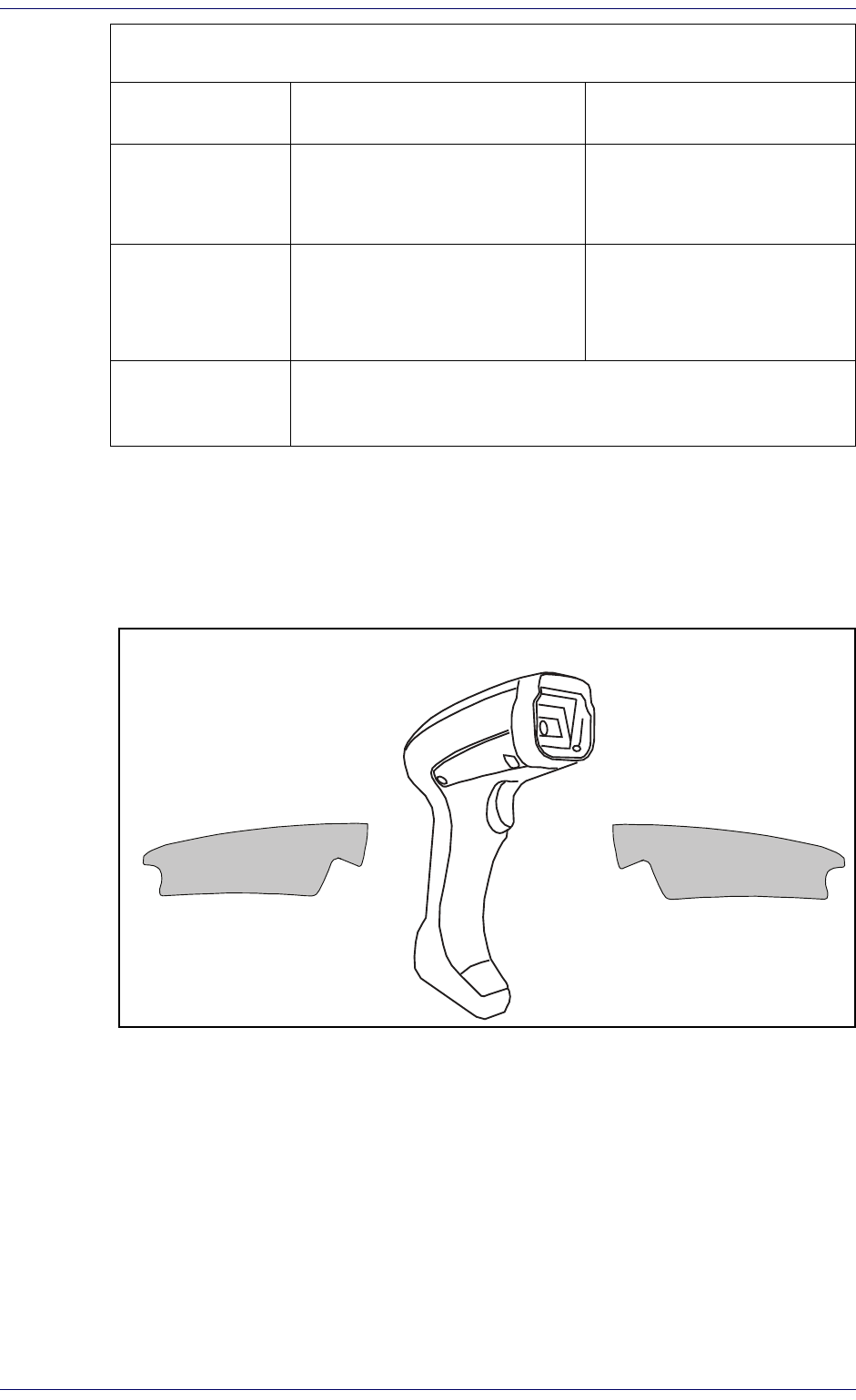
About the Reader ..................................................................................................................................................................................................... 3
PM8500 Compatible Mode: ............................................................................................................................................................................ 3
The BC9xx0™ Base Station/Charger ....................................................................................................................................................................... 4
Battery Safety ........................................................................................................................................................................................................... 5
Programming the Reader ........................................................................................................................................................................................ 6
Configuration Methods ................................................................................................................................................................................... 6
SETUP.......................................................................................................................................................................................................... 7
Unpacking ................................................................................................................................................................................................................. 7
Setting Up the Reader ............................................................................................................................................................................................. 7
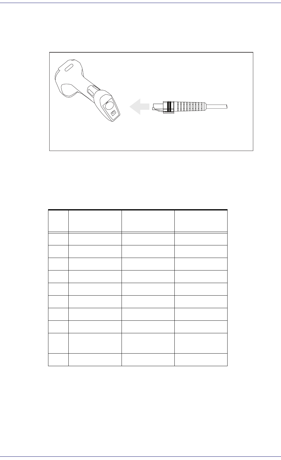
Connecting the Cable (Corded versions) ....................................................................................................................................................... 8
Configuring the Base Station .................................................................................................................................................................................. 9
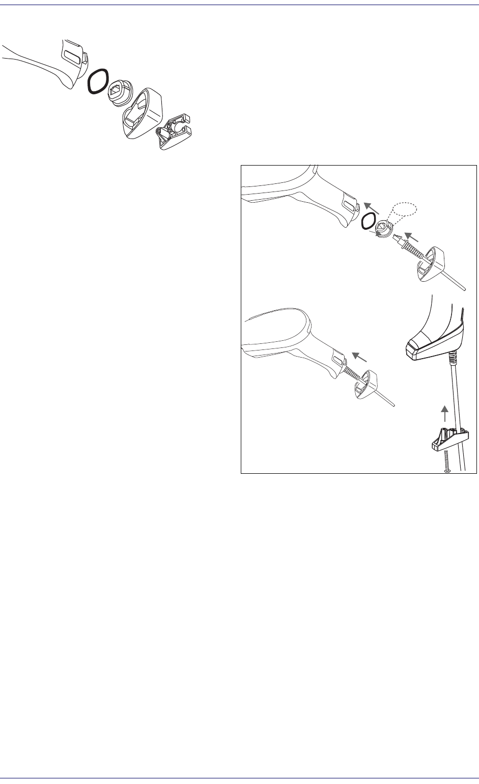
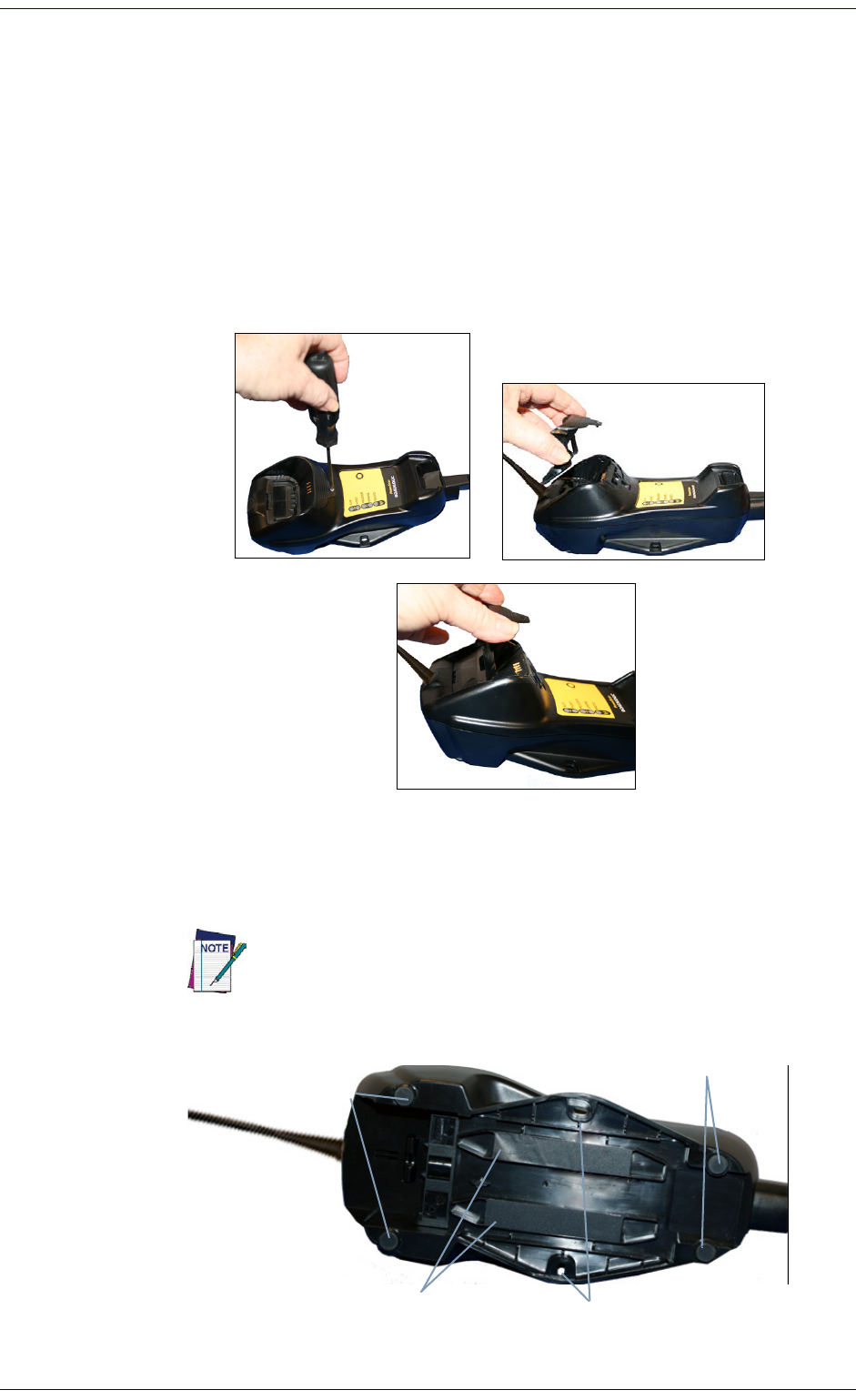
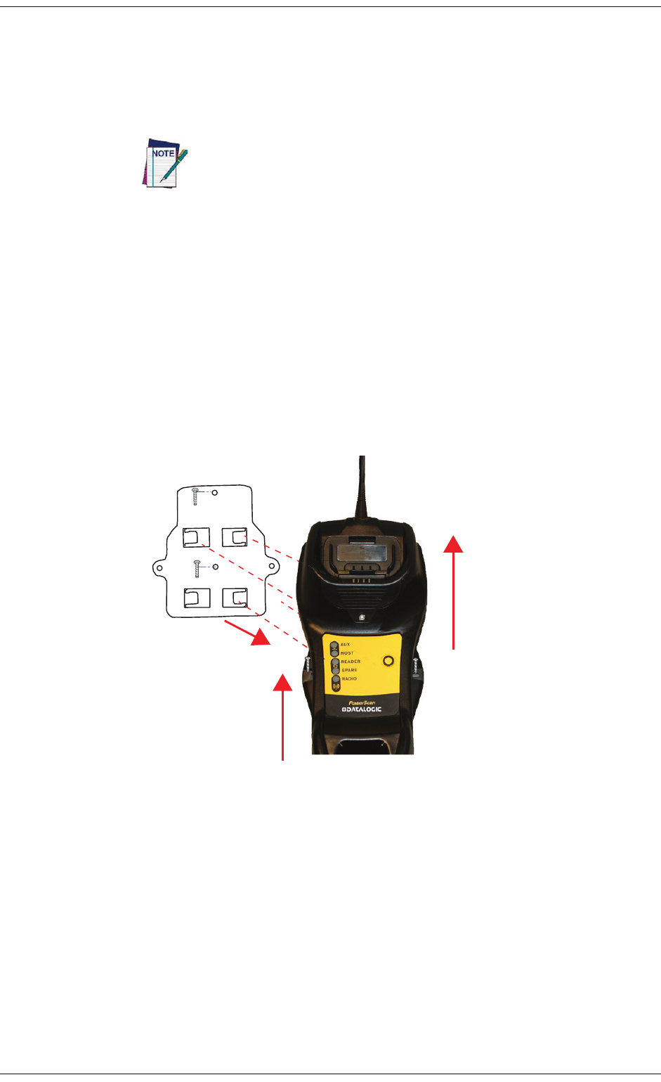
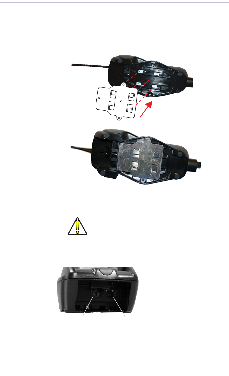
Mounting the BC9xx0 Cradle .................................................................................................................................................................................. 9
Mounting Brackets .......................................................................................................................................................................................... 9
Permanent Mounting ...................................................................................................................................................................................10
Mounting for Portable Use ......................................................................................................
..................................................................... 11
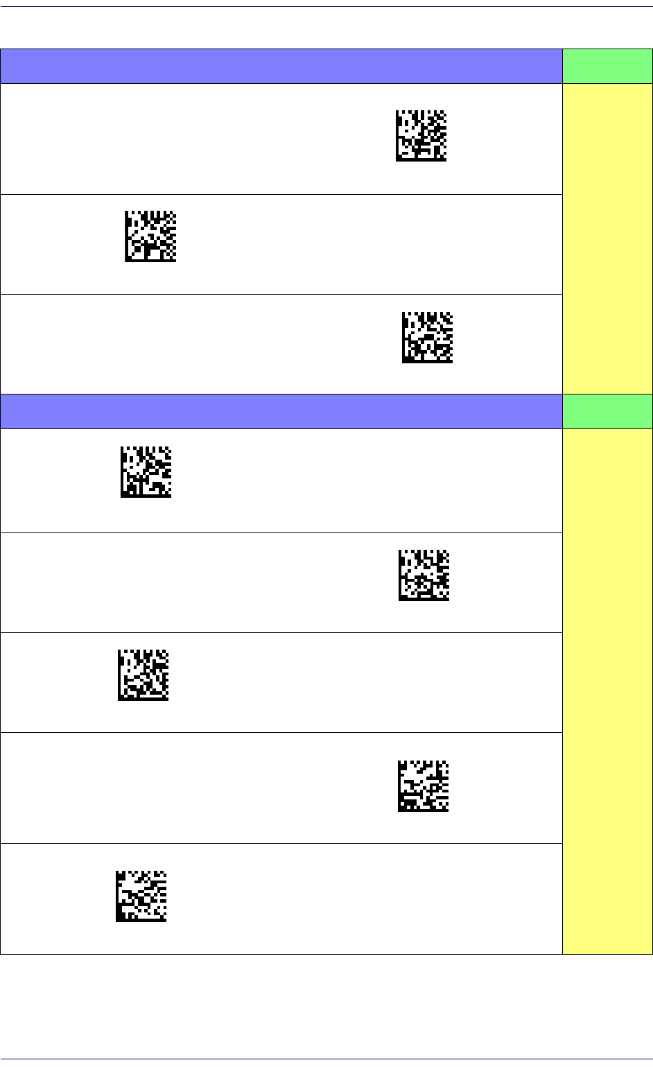
System Connections .....................................................................................................................................................................................12
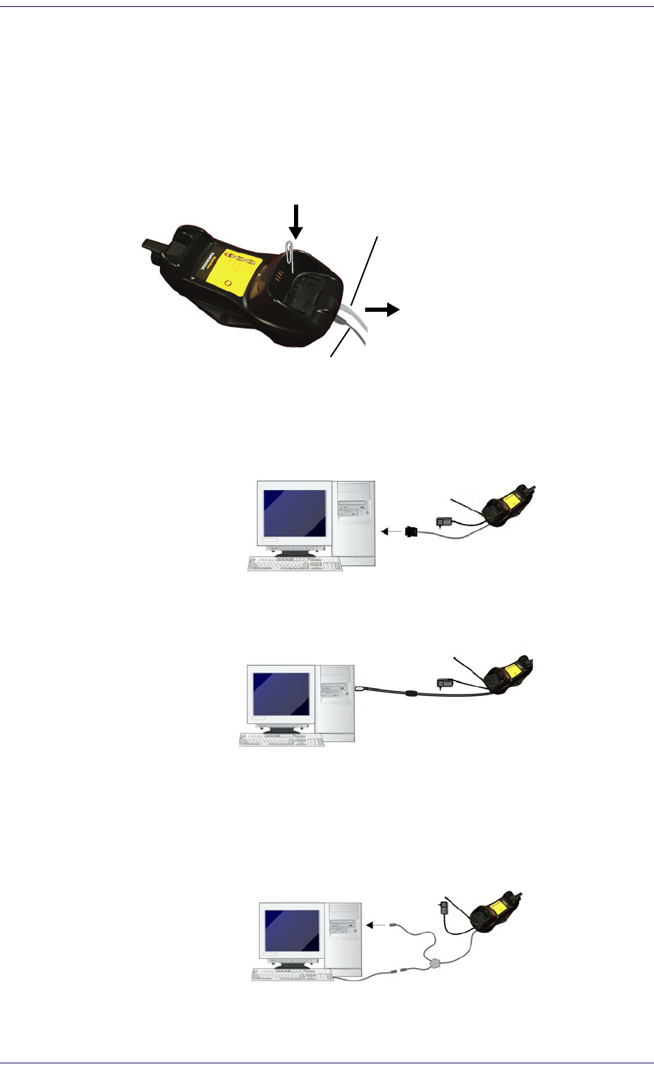
Connecting and Disconnecting the Interface Cable ................................................................................................................................... 13
BC9xx0 Configuration ...........................................................................................................
........................................................................ 14
Interface Selection ................................................................................................................................................................................................. 14
Setting the Interface ..................................................................................................................................................................................... 14
Customizing Configuration Settings ....................................................................................................................................................................17
Configure Interface Settings ........................................................................................................................................................................17
Global Interface Features ........................................................................................................
..................................................................... 17
Configuring Other Features ......................................................................................................
................................................................... 17
Software Version Transmission ....................................................................................................
..............................................................17
Self Test and Statistics .......................................................................................................
..........................................................................17
Resetting the Product Configuration to Defaults ................
...................................................................................................................... 18
Set Date and Time ..............................................................................................................
..........................................................................18
Linking the Reader ................................................................................................................................................................................................. 19
Link Datalogic RF Devices to Base ..............................................................................................................................................................19
Linking to a Bluetooth Adapter in Serial Port Profile (Slave) Mode .........................................................................................................19
Linking to a Bluetooth Adapter in HID mode ......................................................................................
....................................................... 19
Power Off .......................................................................................................................................................................................................20
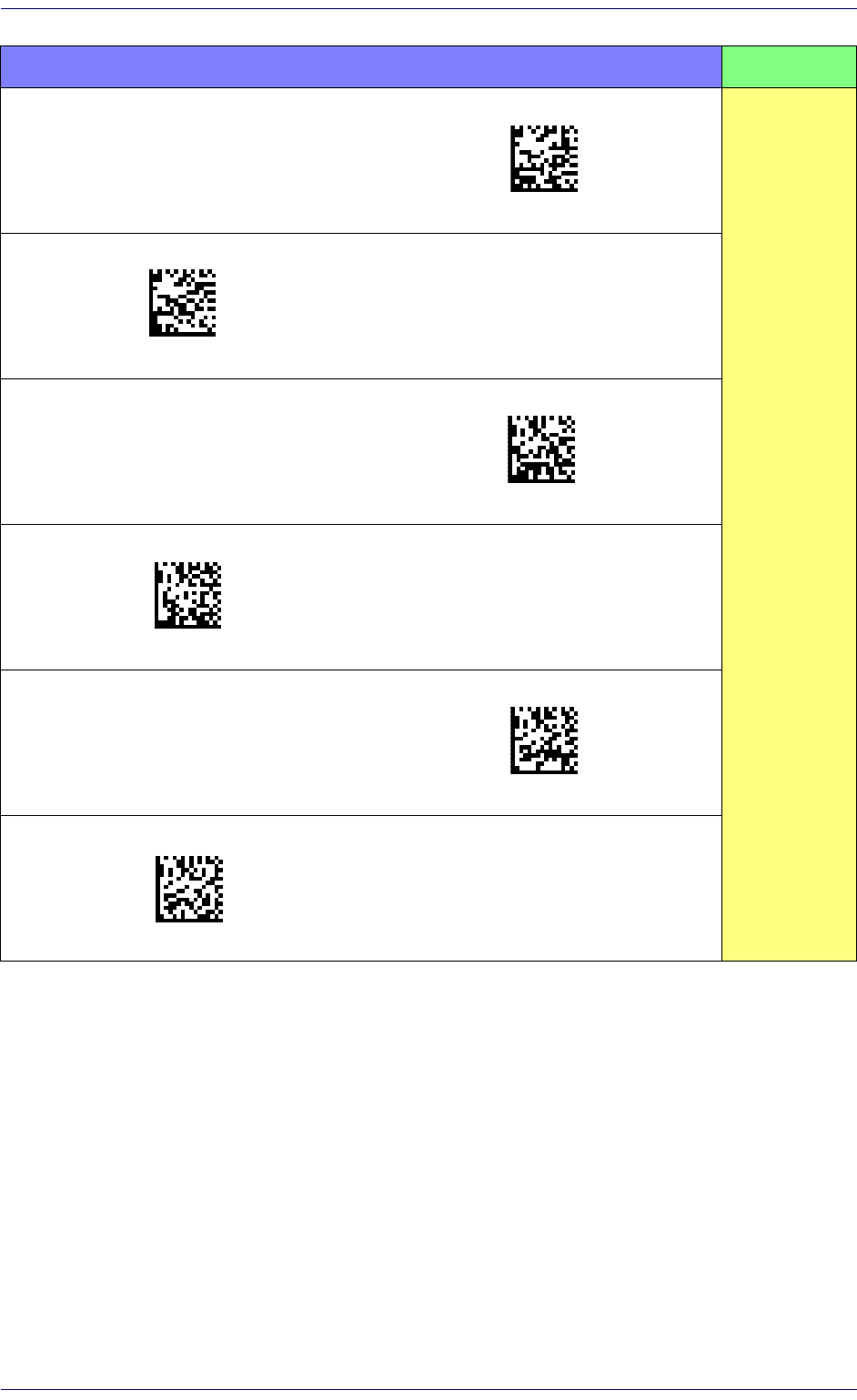
CONFIGURATION USING BAR CODES ..................................................................................................................................................... 21
Configuration Parameters ............................................................................................................................................................................ 21
GLOBAL INTERFACE FEATURES 23
Host Commands — Obey/Ignore .............................................................................................................................................. 23
USB Suspend Mode ..................................................................................................................................................................... 23
RS-232 Only Interface25
Baud Rate ..................................................................................................................................................................................... 26
Data Bits ....................................................................................................................................................................................... 27
Stop Bits ....................................................................................................................................................................................... 27
Parity ............................................................................................................................................................................................ 28
Handshaking Control .................................................................................................................................................................. 29
RS-232/USB-Com Interfaces30
Intercharacter Delay .................................................................................................................................................................... 31
Beep On ASCII BEL ....................................................................................................................................................................... 31
Contents
ii
PowerScan™ PD9530/PBT9500/PM9500
Beep On Not on File .................................................................................................................................................................... 32
ACK NAK Options ......................................................................................................................................................................... 32
ACK Character .............................................................................................................................................................................. 33
NAK Character ............................................................................................................................................................................. 33
ACK NAK Timeout Value ............................................................................................................................................................. 34
ACK NAK Retry Count .................................................................................................................................................................. 34
ACK NAK Error Handling ............................................................................................................................................................. 35
Indicate Transmission Failure ................................................................................................................................................... 35
Disable Character ........................................................................................................................................................................ 36
Enable Character ......................................................................................................................................................................... 36
Keyboard Settings ........................................................................................................................................................................... 37
Country Mode .............................................................................................................................................................................. 38
Send Control Characters ............................................................................................................................................................. 41
Wedge Quiet Interval .................................................................................................................................................................. 42
Intercode Delay ............................................................................................................................................................................ 42
Caps Lock State ........................................................................................................................................................................... 43
Numlock ....................................................................................................................................................................................... 43
USB Keyboard Speed ................................................................................................................................................................... 44
USB Keyboard Numeric Keypad ................................................................................................................................................. 45
USB-OEM Interface ......................................................................................................................................................................... 47
USB-OEM Device Usage ............................................................................................................................................................. 48
Interface Options ......................................................................................................................................................................... 48
Data Format ..................................................................................................................................................................................... 49
Global Prefix/Suffix (Header/Terminator) ..........................................................................................................................................................50
Global AIM ID .......................................................................................................................................................................................................... 51
Set AIM ID Individually for GS1-128 ............................................................................................................................................................ 54
Label ID .................................................................................................................................................................................................................... 55
Label ID: Pre-Loaded Sets ............................................................................................................................................................................55
Individually Set Label ID ............................................................................................................................................................................... 56
Label ID Control ........................................................................................................................................................................... 56
Label ID Symbology Selection − 1D Symbologies .................................................................................................................... 57
Advanced Formatting: User Label Edit ..................................................................................................................................... 61
Case Conversion .......................................................................................................................................................................... 61
Character Conversion .................................................................................................................................................................. 61
Reading Parameters ...................................................................................................................................................................... 63
Double Read Timeout ................................................................................................................................................................. 64
LED AND BEEPER INDICATORS ........................................................................................................................................................... 66
Power On Alert ............................................................................................................................................................................ 66
Good Read: When to Indicate ..................................................................................................................................................... 66
Good Read Beep Type ................................................................................................................................................................. 67
Good Read Beep Frequency ....................................................................................................................................................... 67
Good Read Beep Length ............................................................................................................................................................. 68
Good Read Beep Volume ............................................................................................................................................................ 69
Good Read LED Duration ............................................................................................................................................................ 70
SCANNING FEATURES .......................................................................................................................................................................... 71
Scan Mode .................................................................................................................................................................................... 71
Stand Mode Indication ................................................................................................................................................................ 72
Pick Mode ..................................................................................................................................................................................... 72
Stand Mode Sensitivity ............................................................................................................................................................... 73
Stand Mode Illumination Off Time ............................................................................................................................................ 73
Scanning Active Time .................................................................................................................................................................. 74
Stand Illumination Control ......................................................................................................................................................... 74
Flash On Time .............................................................................................................................................................................. 75
Flash Off Time ............................................................................................................................................................................. 75
Aiming Pointer ............................................................................................................................................................................. 76
Aiming Duration Timer ................................................................................................................................................................ 76
Green Spot Duration ................................................................................................................................................................... 77
Partial Label Reading Control .................................................................................................................................................... 77
Decode Negative Image .............................................................................................................................................................. 78
Image Capture ............................................................................................................................................................................. 78
MULTIPLE LABEL READING ................................................................................................................................................................ 79
Multiple Labels per Frame ......................................................................................................................................................... 79
Multiple Labels Ordering by Code Symbology .......................................................................................................................... 80
Multiple Labels Ordering by Code Length ................................................................................................................................ 80
1D Symbologies ............................................................................................................................................................................... 81
DISABLE ALL SYMBOLOGIES ............................................................................................................................................................... 82
Contents
Product Reference Guide
iii
CODE EAN/UPC .................................................................................................................................................................................... 83
Coupon Control ............................................................................................................................................................................ 83
UPC-A .................................................................................................................................................................................................... 84
UPC-A Enable/Disable ................................................................................................................................................................ 84
UPC-A Check Character Transmission ...................................................................................................................................... 84
Expand UPC-A to EAN-13 .......................................................................................................................................................... 85
UPC-A Number System Character Transmission .................................................................................................................... 85
UPC-A 2D Component ................................................................................................................................................................. 86
UPC-E .................................................................................................................................................................................................... 86
UPC-E Enable/Disable ................................................................................................................................................................ 86
UPC-E Check Character Transmission ...................................................................................................................................... 87
UPC-E 2D Component ................................................................................................................................................................. 87
Expand UPC-E to EAN-13 ........................................................................................................................................................... 88
Expand UPC-E to UPC-A ............................................................................................................................................................. 88
UPC-E Number System Character Transmission .................................................................................................................... 89
GTIN FORMATTING ............................................................................................................................................................................... 89
EAN 13 (JAN 13) .................................................................................................................................................................................... 90
EAN 13 Enable/Disable .............................................................................................................................................................. 90
EAN 13 Check Character Transmission ..................................................................................................................................... 90
EAN-13 Flag 1 Character ............................................................................................................................................................ 91
EAN-13 ISBN Conversion ........................................................................................................................................................... 91
EAN-13 2D Component .............................................................................................................................................................. 92
ISSN ........................................................................................................................................................................................................ 92
ISSN Enable/Disable ................................................................................................................................................................... 92
EAN 8 (JAN 8) ......................................................................................................................................................................................... 93
EAN 8 Enable/Disable ................................................................................................................................................................ 93
EAN 8 Check Character Transmission ....................................................................................................................................... 93
Expand EAN 8 to EAN 13 ............................................................................................................................................................ 94
EAN 8 2D Component ................................................................................................................................................................. 94
UPC/EAN GLOBAL SETTINGS .............................................................................................................................................................. 95
UPC/EAN Price Weight Check .................................................................................................................................................... 95
UPC/EAN Quiet Zones ................................................................................................................................................................ 96
ADD-ONS ............................................................................................................................................................................................... 97
Optional Add-ons ........................................................................................................................................................................ 97
Optional Add-On Timer ............................................................................................................................................................... 98
Optional GS1-128 Add-On Timer ............................................................................................................................................. 100
CODE 39 ............................................................................................................................................................................................... 103
Code 39 Enable/Disable ........................................................................................................................................................... 103
Code 39 Check Character Calculation ...................................................................................................................................... 103
Code 39 Check Character Transmission .................................................................................................................................. 104
Code 39 Start/Stop Character Transmission ......................................................................................................................... 105
Code 39 Full ASCII ...................................................................................................................................................................... 105
Code 39 Quiet Zones ................................................................................................................................................................. 106
Code 39 Length Control ............................................................................................................................................................ 106
Code 39 Set Length 1 ................................................................................................................................................................ 107
Code 39 Set Length 2 ................................................................................................................................................................ 108
TRIOPTIC CODE ................................................................................................................................................................................... 109
Trioptic Code Enable/Disable ................................................................................................................................................... 109
CODE 32 (ITAL PHARMACEUTICAL CODE) ........................................................................................................................................ 109
Code 32 Enable/Disable ........................................................................................................
................................................... 109
Code
32 Feature Setting Exceptions ....................................................................................................................................... 109
Code 32 Check Character Transmission .................................................................................................................................. 110
Code 32 Start/Stop Character Transmission ......................................................................................................................... 110
CODE 39 CIP (FRENCH PHARMACEUTICAL) ..................................................................................................................................... 111
Code 39 CIP Enable/Disable ..................................................................................................................................................... 111
CODE 39 DANISH PPT ........................................................................................................................................................................ 111
Code 39 Danish PPT Enable/Disable ...................................................................................................................................... 111
CODE 39 LAPOSTE .............................................................................................................................................................................. 112
Code 39 LaPoste Enable/Disable ............................................................................................................................................ 112
CODE 39 PZN ...................................................................................................................................................................................... 112
Code 39 PZN Enable/Disable ................................................................................................................................................... 112
CODE 128 ............................................................................................................................................................................................. 113
Code 128 Enable/Disable ......................................................................................................................................................... 113
Expand Code 128 to Code 39 .................................................................................................................................................... 113
Code 128 Check Character Transmission ............................................................................................................................... 114
Code 128 Function Character Transmission .......................................................................................................................... 114
Code 128 Sub-Code Exchange Transmission ......................................................................................................................... 115
Contents
iv
PowerScan™ PD9530/PBT9500/PM9500
Code 128 Quiet Zones ............................................................................................................................................................... 115
Code 128 Length Control .......................................................................................................................................................... 116
Code 128 Set Length 1 .............................................................................................................................................................. 117
Code 128 Set Length 2 .............................................................................................................................................................. 118
GS1-128 ............................................................................................................................................................................................... 119
GS1-128 Enable ......................................................................................................................................................................... 119
GS1-128 2D Component ........................................................................................................................................................... 119
CODE ISBT 128 .................................................................................................................................................................................... 120
ISBT 128 Concatenation ............................................................................................................................................................ 120
ISBT 128 Force Concatenation ................................................................................................................................................. 120
ISBT 128 Concatenation Mode ................................................................................................................................................. 121
ISBT 128 Dynamic Concatenation Timeout ............................................................................................................................ 122
ISBT 128 Advanced Concatenation Options ........................................................................................................................... 122
INTERLEAVED 2 OF 5 (I 2 OF 5) ......................................................................................................................................................... 123
I 2 of 5 Enable/Disable ............................................................................................................................................................. 123
I 2 of 5 Check Character Calculation ........................................................................................................................................ 124
I 2 of 5 Check Character Transmission .................................................................................................................................... 125
I 2 of 5 Length Control .............................................................................................................................................................. 125
I 2 of 5 Set Length 1 .................................................................................................................................................................. 126
I 2 of 5 Set Length 2 .................................................................................................................................................................. 127
INTERLEAVED 2 OF 5 CIP HR ............................................................................................................................................................ 128
Interleaved 2 of 5 CIP HR Enable/Disable .............................................................................................................................. 128
FOLLETT 2 OF 5 .................................................................................................................................................................................. 128
Follett 2 of 5 Enable/Disable ................................................................................................................................................... 128
STANDARD 2 OF 5 .............................................................................................................................................................................. 129
Standard 2 of 5 Enable/Disable .............................................................................................................................................. 129
Standard 2 of 5 Check Character Calculation ......................................................................................................................... 129
Standard 2 of 5 Check Character Transmission ..................................................................................................................... 130
Standard 2 of 5 Length Control ............................................................................................................................................... 130
Standard 2 of 5 Set Length 1 ................................................................................................................................................... 131
Standard 2 of 5 Set Length 2 ................................................................................................................................................... 132
INDUSTRIAL 2 OF 5 ............................................................................................................................................................................. 133
Industrial 2 of 5 Enable/Disable .............................................................................................................................................. 133
Industrial 2 of 5 Check Character Calculation ........................................................................................................................ 133
Industrial 2 of 5 Check Character Transmission .................................................................................................................... 134
Industrial 2 of 5 Length Control ............................................................................................................................................... 134
Industrial 2 of 5 Set Length 1 ................................................................................................................................................... 135
Industrial 2 of 5 Set Length 2 ................................................................................................................................................... 136
CODE IATA ........................................................................................................................................................................................... 137
IATA Enable/Disable ................................................................................................................................................................. 137
IATA Check Character Transmission ....................................................................................................................................... 137
CODABAR ............................................................................................................................................................................................ 138
Codabar Enable/Disable ........................................................................................................................................................... 138
Codabar Check Character Calculation ..................................................................................................................................... 138
Codabar Check Character Transmission ................................................................................................................................. 139
Codabar Start/Stop Character Transmission ......................................................................................................................... 139
Codabar Start/Stop Character Set .......................................................................................................................................... 140
Codabar Start/Stop Character Match ............................................................................................
......................................... 140
Coda
bar Quiet Zones ................................................................................................................................................................ 141
Codabar Length Control ............................................................................................................................................................ 141
Codabar Set Length 1 ................................................................................................................................................................ 142
Codabar Set Length 2 ................................................................................................................................................................ 143
ABC CODABAR .................................................................................................................................................................................... 144
ABC Codabar Enable/Disable ................................................................................................................................................... 144
ABC Codabar Concatenation Mode .......................................................................................................................................... 144
ABC Codabar Dynamic Concatenation Timeout ..................................................................................................................... 145
ABC Codabar Force Concatenation .......................................................................................................................................... 146
CODE 11 ............................................................................................................................................................................................... 147
Code 11 Enable/Disable ........................................................................................................................................................... 147
Code 11 Check Character Calculation ...................................................................................................................................... 147
Code 11 Check Character Transmission .................................................................................................................................. 148
Code 11 Length Control ............................................................................................................................................................ 148
Code 11 Set Length 1 ................................................................................................................................................................ 149
Code 11 Set Length 2 ................................................................................................................................................................ 150
GS1 DATABAR™ OMNIDIRECTIONAL ................................................................................................................................................. 151
GS1 DataBar™ Omnidirectional Enable/Disable .................................................................................................................... 151
GS1 DataBar™ Omnidirectional GS1-128 Emulation ............................................................................................................. 151
Contents
Product Reference Guide
v
GS1 DataBar™ Omnidirectional 2D Component ..................................................................................................................... 152
GS1 DATABAR™ EXPANDED .............................................................................................................................................................. 152
GS1 DataBar™ Expanded Enable/Disable ............................................................................................................................... 152
GS1 DataBar™ Expanded GS1-128 Emulation ........................................................................................................................ 153
GS1 DataBar™ Expanded 2D Component ................................................................................................................................ 153
GS1 DataBar™ Expanded Length Control ................................................................................................................................ 154
GS1 DataBar™ Expanded Set Length 1 .................................................................................................................................... 155
GS1 DataBar™ Expanded Set Length 2 .................................................................................................................................... 156
GS1 DATABAR™ LIMITED .................................................................................................................................................................... 157
GS1 DataBar™ Limited Enable/Disable ................................................................................................................................... 157
GS1 DataBar™ Limited GS1-128 Emulation ............................................................................................................................ 157
GS1 DataBar™ Limited 2D Component .................................................................................................................................... 158
CODE 93 ............................................................................................................................................................................................... 158
Code 93 Enable/Disable ........................................................................................................................................................... 158
Code 93 Check Character Calculation ...................................................................................................................................... 159
Code 93 Check Character Transmission .................................................................................................................................. 159
Code 93 Length Control ............................................................................................................................................................ 160
Code 93 Set Length 1 ................................................................................................................................................................ 161
Code 93 Set Length 2 ................................................................................................................................................................ 162
Code 93 Quiet Zones ................................................................................................................................................................. 163
MSI ....................................................................................................................................................................................................... 163
MSI Enable/Disable .................................................................................................................................................................. 163
MSI Check Character Calculation ............................................................................................................................................. 164
MSI Check Character Transmission ......................................................................................................................................... 164
MSI Length Control ................................................................................................................................................................... 165
MSI Set Length 1 ....................................................................................................................................................................... 166
MSI Set Length 2 ....................................................................................................................................................................... 167
PLESSEY .............................................................................................................................................................................................. 168
Plessey Enable/Disable ............................................................................................................................................................ 168
Plessey Check Character Calculation ...................................................................................................................................... 168
Plessey Check Character Transmission .................................................................................................................................. 169
Plessey Length Control ............................................................................................................................................................. 169
Plessey Set Length 1 ................................................................................................................................................................ 170
Plessey Set Length 2 ................................................................................................................................................................ 171
2D Symbologies ............................................................................................................................................................................. 173
2D Global Features ...............................................................................................................................................................................................173
2D Maximum Decoding Time ................................................................................................................................................... 174
2D Structured Append .............................................................................................................................................................. 175
2D Normal/Inverse Symbol Control ........................................................................................................................................ 175
AZTEC CODE ........................................................................................................................................................................................ 176
Aztec Code Enable / Disable .................................................................................................................................................... 176
Aztec Code Length Control ....................................................................................................................................................... 176
Aztec Code Set Length 1 ........................................................................................................................................................... 177
Aztec Code Set Length 2 ........................................................................................................................................................... 178
CHINA SENSIBLE CODE ...................................................................................................................................................................... 179
China Sensible Code Enable / Disable .................................................................................................................................... 179
China Sensible Code Length Control ....................................................................................................................................... 179
China Sensible Code Set Length 1 ........................................................................................................................................... 180
China Sensible Code Set Length 2 ........................................................................................................................................... 181
DATA MATRIX ...................................................................................................................................................................................... 182
Data Matrix Enable / Disable ................................................................................................................................................... 182
Data Matrix Square/Rectangular Style .................................................................................................................................. 182
Data Matrix DPM Decoding Safety .......................................................................................................................................... 183
Data Matrix Length Control ...................................................................................................................................................... 184
Data Matrix Set Length 1 ......................................................................................................................................................... 184
Data Matrix Set Length 2 ......................................................................................................................................................... 185
MAXICODE ........................................................................................................................................................................................... 186
Maxicode Enable / Disable ....................................................................................................................................................... 186
Maxicode Primary Message Transmission ............................................................................................................................ 186
Maxicode Length Control .......................................................................................................................................................... 187
Maxicode Set Length 1 ............................................................................................................................................................. 187
Maxicode Set Length 2 ............................................................................................................................................................. 188
PDF417 ................................................................................................................................................................................................ 189
PDF417 Enable / Disable ......................................................................................................................................................... 189
PDF417 Length Control ............................................................................................................................................................ 189
PDF417 Set Length 1 ................................................................................................................................................................ 190
PDF417 Set Length 2 ................................................................................................................................................................ 191
Contents
vi
PowerScan™ PD9530/PBT9500/PM9500
MICRO PDF417 ................................................................................................................................................................................... 192
Micro PDF417 Enable / Disable ............................................................................................................................................... 192
Micro PDF417 Code 128 GS1-128 Emulation ......................................................................................................................... 192
Micro PDF417 Length Control .................................................................................................................................................. 193
Micro PDF417 Set Length 1 ...................................................................................................................................................... 193
Micro PDF417 Set Length 2 ...................................................................................................................................................... 194
QR CODE .............................................................................................................................................................................................. 195
QR Code Enable / Disable ........................................................................................................................................................ 195
QR Code Length Control ........................................................................................................................................................... 195
QR Code Set Length 1 ............................................................................................................................................................... 196
QR Code Set Length 2 ............................................................................................................................................................... 197
MICRO QR CODE ................................................................................................................................................................................. 197
Micro QR Code Enable/Disable ................................................................................................................................................ 197
Micro QR Code Length Control ................................................................................................................................................. 198
Micro QR Code Set Length 1 ..................................................................................................................................................... 198
Micro QR Code Set Length 2 ..................................................................................................................................................... 199
UCC COMPOSITE ................................................................................................................................................................................. 200
UCC Composite Enable / Disable ............................................................................................................................................. 200
UCC Optional Composite Timer ................................................................................................................................................ 201
POSTAL CODE SELECTION ................................................................................................................................................................. 202
Postnet BB Control ................................................................................................................................................................... 203
Motion Features ........................................................................................................................................................................... 205
Motion Aiming Control .............................................................................................................................................................. 205
Motion Sensitivity ..................................................................................................................................................................... 206
Motionless Timeout .................................................................................................................................................................. 206
Wireless Features ......................................................................................................................................................................... 207
WIRELESS BEEPER FEATURES ......................................................................................................................................................... 209
Good Transmission Beep .......................................................................................................................................................... 209
Beep Frequency ......................................................................................................................................................................... 209
Beep Duration ............................................................................................................................................................................ 210
Beep Volume .............................................................................................................................................................................. 211
Disconnect Beep ........................................................................................................................................................................ 211
Docking Beep ............................................................................................................................................................................. 212
Leash Alarm ............................................................................................................................................................................... 212
CONFIGURATION UPDATES ............................................................................................................................................................... 214
Automatic Configuration Update ............................................................................................................................................. 214
Copy Configuration to Scanner ................................................................................................................................................ 214
Copy Configuration to Base Station ........................................................................................................................................ 214
BATCH FEATURES .............................................................................................................................................................................. 215
Batch Mode ................................................................................................................................................................................ 215
Send Batch ................................................................................................................................................................................. 215
Erase Batch Memory ................................................................................................................................................................ 216
RF Batch Mode Transmit Delay ............................................................................................................................................... 216
DIRECT RADIO AUTOLINK .................................................................................................................................................................. 217
RF ADDRESS STAMPING .................................................................................................................................................................... 217
Source Radio Address Transmission ...................................................................................................................................... 217
Source Radio Address Delimiter Character ............................................................................................................................ 218
REAL TIME CLOCK (RTC) CONFIGURATION ....................................................................................................................................... 219
Current Date .............................................................................................................................................................................. 219
Current Time .............................................................................................................................................................................. 219
Date Tx Format .......................................................................................................................................................................... 220
Time Tx Format .......................................................................................................................................................................... 220
Date-Time Separator ................................................................................................................................................................ 221
Date-Time Transmission Order ............................................................................................................................................... 222
PBT9500-Only Features................................................................................................................................................................ 223
BLUETOOTH SECURITY FEATURES ................................................................................................................................................... 223
Bluetooth Security Mode .......................................................................................................................................................... 224
Bluetooth PIN Code ................................................................................................................................................................... 224
Select PIN Code Length ............................................................................................................................................................ 224
Set PIN Code .............................................................................................................................................................................. 225
OTHER BLUETOOTH FEATURES ........................................................................................................................................................ 226
Bluetooth Poll Rate ................................................................................................................................................................... 226
Power Off ................................................................................................................................................................................... 227
Powerdown Timeout ................................................................................................................................................................. 227
Bluetooth HID Variable PIN Code ............................................................................................................................................ 228
Bluetooth HID Alt Mode ............................................................................................................................................................ 229
Bluetooth HID Send Unknown ASCII Char .............................................................................................................................. 229
Contents
Product Reference Guide
vii
Bluetooth Max Client ................................................................................................................................................................ 230
Bluetooth Friendly Name ......................................................................................................................................................... 231
Bluetooth Reconnect Attempt Mode ...................................................................................................................................... 231
HID Country Mode ..................................................................................................................................................................... 232
PM9500-Only Features................................................................................................................................................................. 235
STAR Radio Protocol Timeout .................................................................................................................................................. 235
STAR Radio Transmit Mode ..................................................................................................................................................... 236
Changing System Speed ........................................................................................................................................................... 237
Compatibility with PM8500.......................................................................................................................................................... 238
Compatibility mode .....................................................................................................................................................................................238
Changing from Normal to Compatible Mode ......................................................................................................................... 238
Changing from Compatible Mode back to Normal ................................................................................................................ 239
Base Address Stamping ........................................................................................................................................................... 240
Base Address Delimiter Character .......................................................................................................................................... 240
RS-485 Master Header/Terminator ( Prefix/Suffix) ............................................................................................................. 241
RS-485 Cradle Address ............................................................................................................................................................. 241
RS-485 Slave Minimum Address ............................................................................................................................................. 242
RS-485 Slave Maximum Address ............................................................................................................................................ 242
RS-485 Network Working Mode .............................................................................................................................................. 243
RS-485 Network Warning Message ........................................................................................................................................ 243
RS-485 Transmission Warning Message ............................................................................................................................... 244
RS-485 Network Baud Rate ..................................................................................................................................................... 244
Display and Keyboard Features................................................................................................................................................... 245
Display Operating Mode ........................................................................................................................................................... 245
Display Off Timeout .................................................................................................................................................................. 246
Backlight Enable ........................................................................................................................................................................ 246
Display Contrast ........................................................................................................................................................................ 247
Font Size ..................................................................................................................................................................................... 247
Enable/disable buttons ............................................................................................................................................................ 248
CONFIGURE ACTIONS FOR FUNCTION KEYS .................................................................................................................................... 249
Action Configuration for Function Keys .................................................................................................................................. 250
Configure Actions for F1 ........................................................................................................................................................... 250
Configure Actions for F2 ........................................................................................................................................................... 250
Define Strings ............................................................................................................................................................................ 251
Set String ID ............................................................................................................................................................................... 252
Set String Header ...................................................................................................................................................................... 252
Set String Terminator ............................................................................................................................................................... 253
REFERENCES......................................................................................................................................................................................... 255
RS-232 Parameters .............................................................................................................................................................................................256
RS-232 Only .................................................................................................................................................................................................256
RS-232/USB COM Parameters ......................................................................................................
............................................................257
Keyboard Interface ...............................................................................................................................................................................................264
Wedge Quiet Interval ..................................................................................................................................................................................264
Intercharacter Delay ...........................................................................................................
........................................................................265
Intercode Delay ..................................................................................................................
..........................................................................266
Symbologies .........................................................................................................................................................................................................267
Datamatrix DPM Decoding Safety .............................................................................................................................................................267
Set Length ....................................................................................................................................................................................................267
Data Editing ..........................................................................................................................................................................................................269
Global Prefix/Suffix .....................................................................................................................................................................................270
Global AIM ID ................................................................................................................................................................................................270
Label ID .........................................................................................................................................................................................................272
Character Conversion ............................................................................................................
......................................................................277
Reading Parameters ............................................................................................................................................................................................278
Good Read LED Duration ............................................................................................................................................................................278
Scanning Features ...............................................................................................................................................................................................279
Scan Mode ....................................................................................................................................................................................................279
Stand Mode Off Time ..................................................................................................................................................................................280
Scanning Active Time ...........................................
.......................................................................................................................................281
Aiming Duration Time .................................................................................................................................................................................282
Flash On Time ..............................................................................................................................................................................................283
Flash Off Time ...................................................................................................................
..........................................................................284
Multiple Labels Ordering by Code Symbology ..........................................................................................................................................285
Motion Features ...................................................................................................................................................................................................287
Motionless Timeout ....................................................................................................................................................................................287
Wireless Features ................................................................................................................................................................................................288
Contents
viii
PowerScan™ PD9530/PBT9500/PM9500
Automatic Configuration Update ...............................................................................................................................................................288
RF Address Stamping .................................................................................................................................................................................288
PM9500-Only Features ..............................................................................................................................................................................290
Changing System Speed in Normal Mode ...........................................................................................
................................... 290
Bluetooth-Only Features ...........................................................................................................................................................................290
MESSAGE FORMATTING....................................................................................................................................................................... 293
Cursor Control ..............................................................................................................................................................................................294
Font Selection ..............................................................................................................................................................................................294
Clearing Display .................................................................................................................
..........................................................................294
LED and Beeper Control .............................................................................................................................................................................295
Setting RTC ...................................................................................................................................................................................................295
TECHNICAL SPECIFICATIONS ............................................................................................................................................................... 297
Imager Labeling ....................................................................................................................................................................................................301
Standard Cable Pinouts .......................................................................................................................................................................................302
LED and Beeper Indications ................................................................................................................................................................................303
Error Codes ...........................................................................................................................................................................................................304
Base Station Indications (Cordless Models ONLY) ..................................................................................................................................304
SAMPLE BAR CODES............................................................................................................................................................................. 305
STANDARD DEFAULTS.......................................................................................................................................................................... 309
KEYPAD.................................................................................................................................................................................................. 323
SCANCODE TABLES............................................................................................................................................................................... 325
Control Character Emulation ..............................................................................................................................................................................325
Single Press and Release Keys ..................................................................................................................................................................325
Interface Type PC AT PS/2, USB-Keyboard or USB-Keyboard for APPLE ......................................................................................................326
Interface Type PC AT PS/2 Alt Mode or USB-Keyboard Alt Mode ..................................................................................................................328
Digital Interface ....................................................................................................................................................................................................330
IBM31xx 102-key .................................................................................................................................................................................................331
IBM XT ...................................................................................................................................................................................................................332
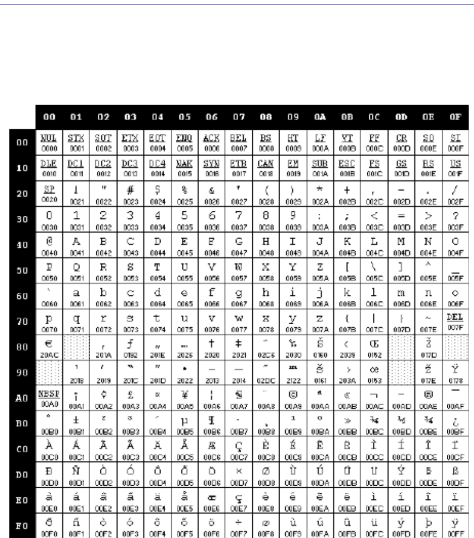
Microsoft Windows Codepage 1252 ..................................................................................................................................................................333
Product Reference Guide
1
Chapter 1
Introduction
About this Manual
This Product Reference Guide (PRG) is provided for users seeking advanced
technical information, including connection, programming, maintenance
and specifications. The Quick Reference Guide (QRG) and other publications
associated with this product are downloadable free of charge from the web-
site listed on the back co
ver of this manual.
Overview
Chapter 1, (this chapter) presents information about manual conventions,
and an overview of the reader, its features and operation.
Chapter 2, Setup presents information about unpacking, cable connection
information and setting up the reader.
Chapter 3, Configuration Using Bar Codes provides instructions and bar
code labels for customizing your reader. There are different sections for
i
nterface types, general features, data formatting, symbology-specific and
model-specific features.
Chapter 4, References provides background information and detailed
instructions for more complex programming items.
Chapter 5, Message Formatting gives details for programming options.
Appendix A, Technical Specifications lists physical and performance
charac-
teristics, as well as environmental and regulatory specifications. It also pro-
vides standard cable pinouts
and LED/Beeper functions.
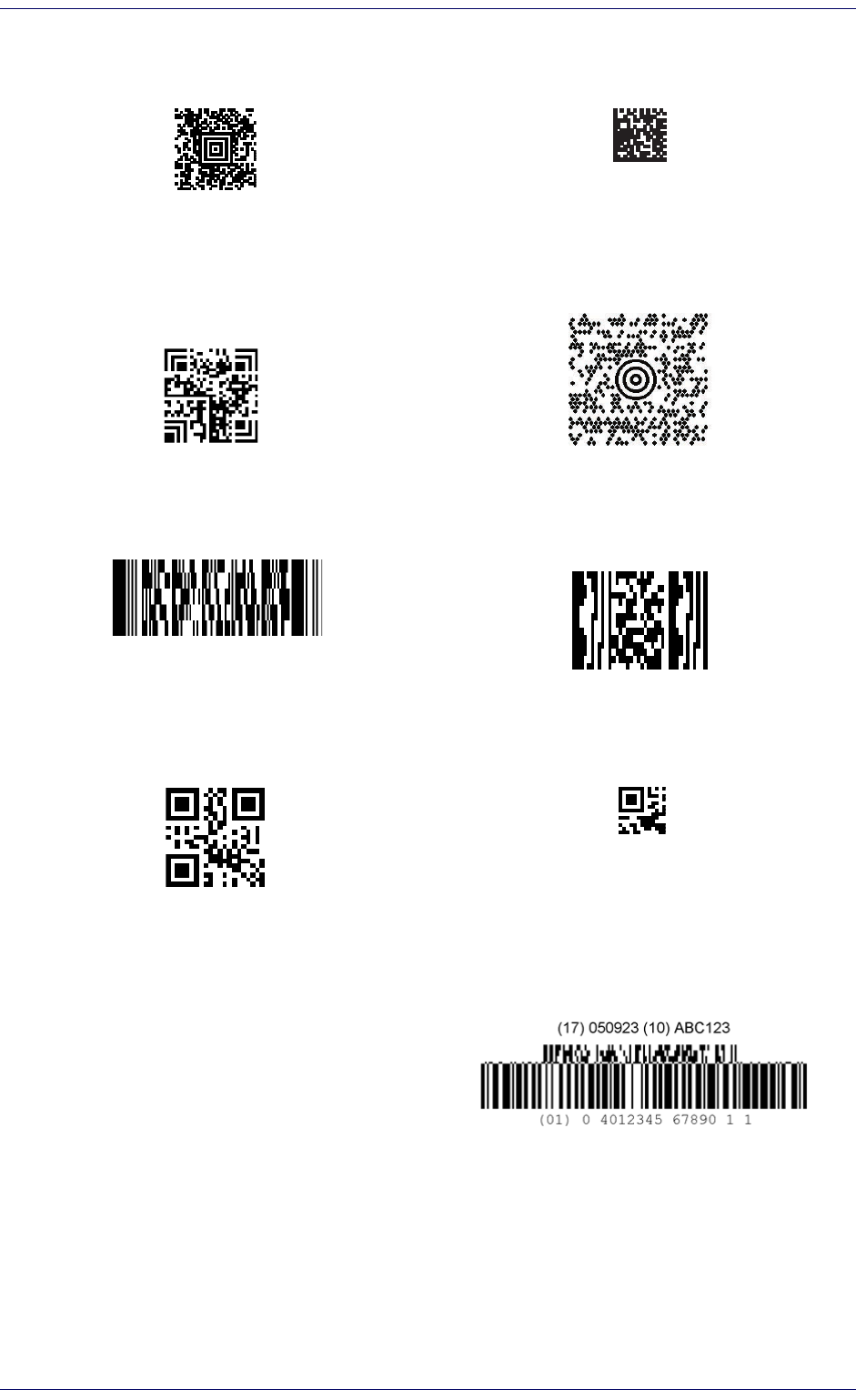
Appendix B, Sample Bar Codes offers sample bar code
s for several common
symbologies.
Appendix C, Standard Defaults references common factory default settings
for reader features and options.
Appendix D, Keypad includes numeric bar codes to be
scanned for certain
parameter settings.
Appendix E, Scancode Tables lists control character emulation information
for Wedge and USB Keybo
ard interfaces.
Introduction
2
PowerScan™ PD9530/PBT9500/PM9500
Manual Conventions
The following conventions are used in this document:
The symbols listed below are used in this manual to notify the reader of key
issues or
procedures that must be observed when using the reader:
Notes contain information necessary for properly diagnosing,
repairing and operating the reader.
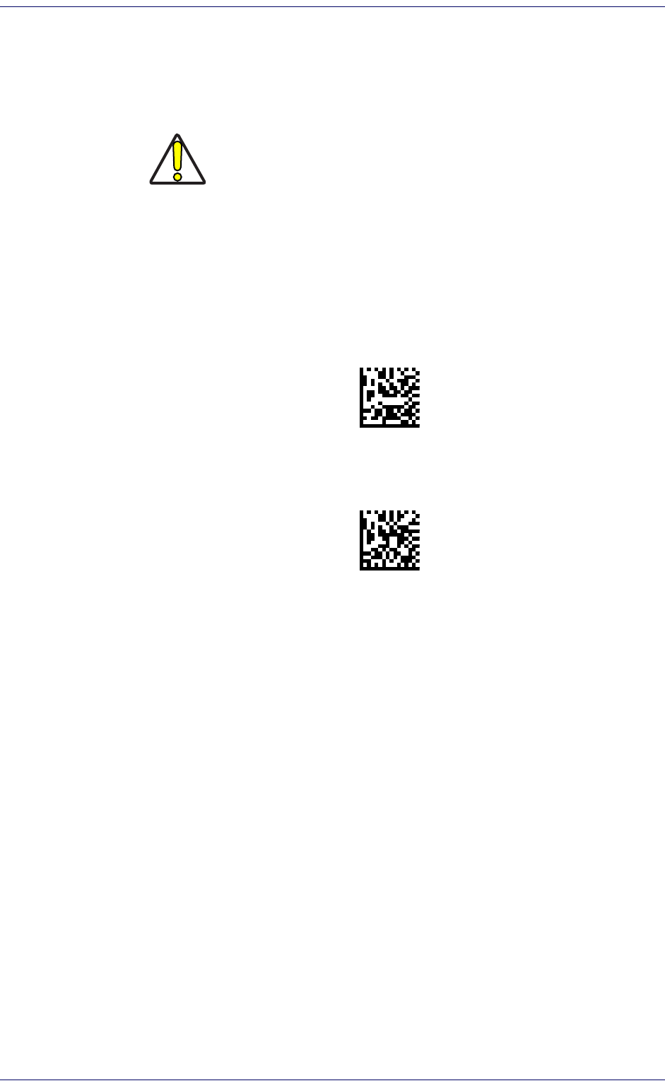
CAUTION
The CAUTION symbol advises you of actions
that could damage
equipment or property.
References
Current versions of this Product Reference Guide (PRG), Quick Reference
Guide (QRG), the Datalogic Aladdin™ Configuration application, and any
other manuals, instruction sheets and utilities for this product can be down-
loaded from the website listed below. Alternatively, printed copies or prod-
uct support CDs for most products can be purchased
through your Datalogic
reseller.
Technical Support
Datalogic Website Support
The Datalogic website (www.datalogic.com) is the complete source for tech-
nical support and information for Datalogic produ
cts. The site offers product
support, warranty information, product manuals, product tech notes, soft-
ware updates, demos, and instructions for returning products for repair.
Reseller Technical Support
An excellent source for technical assistance and information is an autho-
rized Datalogic reseller. A reseller is acqu
ainted with specific types of busi-
nesses, application software, and computer syst
ems and can provide
individualized assistance.
Telephone Technical Support
If you do not have internet or email access, you may contact Datalogic tech-
nical support at (541) 349-8283 or check the back cover of your manual for
mor
e contact information.
About the Reader
Product Reference Guide
3
About the Reader
The PowerScan 2D is a family of feature-rich and rugged area image readers.
It is offered in several different models to better fit the different needs of
each customer.
The main model categories are:
PD9530-XX: Corded models.
PM9500-XX: STAR-System(tm) models.
PBT9500-XX: Bluetooth models.
Within each category, further differentiating features are available, described
by
the part number suffix:
D: models equipped with display
DPM: models with laser, ink jet and dot peen reading
capability
HP: models with autofocus optic
Typically, units are factory-programmed for
the most common terminal and
communications settings. If you need to modify any programmable settings,
custom configuration can be done by scanning the programming barcodes
within this guide or with Datalogic Aladdin™, available from the Datalogic
website. See "Datalogic Aladdin™" on
page 6 for more information.
Advancements in the LED technology used in the imager-based readers sig-
nificantly improve the illumination of the target field of view, resulting in
higher scan efficiency. Whether used in Single Trigger or Continuous Mode,
the ergonomic design of the reader will help to promote comfortable han-
dling during extended periods of use.
In addition, the reader can be set up t
o read and output data from USA
Driver License PDF417 bar codes. For more information reference the USA
Driver License Parsing Quick Reference Guide (QRG), available on the Data-
logic website.
See "Interface Selection" on
page 14 for a listing and descriptions of avail-
able interface sets by model type.
PM8500 Compatible Mode:
Powerscan PM9500 offers a limited set of features compatible with the pre-
vious PM8500 family. To access those features, you have to program the
system th
rough the Compatibility Mode parameter (see "Compatibility
mode" on
page 238 of the Wireless Configuration chapter).
When in normal mode, the same parameter can be used to configure the
co
mmunication speed.
Introduction
4
PowerScan™ PD9530/PBT9500/PM9500
The BC9xx0™ Base Station/Charger
The BC9xx0 base station, when paired with one or more PowerScan™ 9500
readers, builds a Cordless Reading System for the collection, decoding and
transmission of bar code data. It can be connected to a Host PC via RS-232,
USB, or KBD Wedge, and is suited for single-cradle layouts. The BC91x0
models also provide a spare battery charger slot.
The label on the cradle contains LED indicators and a multi-function button.
Whe
n
the button is pressed for less than 5 seconds, the cradle will transmit a
"broadcast" message." When the broadcast is sent, all properly configured
scanners (Radio RX Timeout set to keep the radio "awake") that are linked to
that base and within radio range coverage will emit a beep and blink within 5
seconds. This functionality is useful to:
verify which scanners are linked to a certain
b
a
se station
detect a scanner forgotten somewhere
When the button is pressed for longer than 5
seco
nds, all paired scanners will be unpaired.
The LEDs signal the BC9xx0-BT status, as shown in Table 1 on page 4.
Table 1. LED Status
LED STATUS
Aux Yellow On = BC9xx0 is powered through an external power supply.
Host Yellow On = BC9xx0 is powered by the Host.
Reader
Green On = the reader battery is completely charged.
Red On = the reader battery is charging.
Orange Blinking = reader battery fault - replace battery.
Red / Green Alternatively Blinki
ng =
charging error - see "
Error Codes"
on page 304
.
Off = reader not in the cradle or not properly inserted.
Spare
(BC91x0
models
only)
Green On = the spare battery is completely charged.
Orange Blinking = spare battery fault - replace spare battery.
Red/Green Alternatively Blinking = charging error - see "
Error Codes" on
page 304
.
Off = no spare battery in the housing or battery not fully inserted.
Radio Yellow Blinking = radio activity.
Ethernet
(Ethernet
models
only)
Green Blinking = Ethernet activity.
See "Base Station Indications (Cordless Models ONLY)" on page 304 for more
specific details on the LEDs.
Battery Safety
Product Reference Guide
5
Battery Safety
To reinstall, charge and/or perform any other action on the battery, follow
the instructions in this manual.
WARNING
CAUTION
Always charge the battery at 32° – 104°F (0° - 40°C) temperature range.
Use only the authorized power supplies, battery pack, chargers, and docks supplied by
your D
atalogic reseller. The use of any other power supplies can damage the device and
void your warranty.
Do not disassemble or modify the battery. The battery
contains safety and protection
devices, which, if damaged, may cause the battery to generate heat, explode or ignite.
Do not place the battery in or near fire, on stoves
or other high temperature locations.
Do not place the battery in direct sunlight, or us
e or store the battery inside cars in hot
weather. Doing so may cause the battery to generate heat, explode or ignite. Using the
battery in this manner may also result in a loss of performance and a shortened life
expectancy.
Do not place the battery in microwave ovens, high-
pressure containers or on induction
cookware.
Immediately discontinue use of the battery if, while using, charging or storing the battery,
th
e battery emits an unusual smell, feels hot, changes color or shape, or appears abnor-
mal in any other way.
Do not replace the battery pack when the device is turned on.
Do not remove or damage the battery pack’s label.
Do not use the battery pack if it is damaged in any part.
Battery pack usage by children should be supervised.
Do not discharge the battery using any device excep
t
for the scanner. When the battery
is used in devices other than the designated product, it may damage the battery or
reduce its life expectancy. If the device causes an abnormal current to flow, it may cause
the battery to become hot, explode or ignite and cause serious injury.
Lithium-ion battery packs may get hot, explode or ignite and cause serious injury if
exposed to abusive conditions. Be sure to follow the safety warnings listed below:
Do not place the battery pack in fire or heat.
Do not connect the positive terminal and negati
ve terminal of the battery pack to each
other with any metal object (such as wire).
Do not carry or store the battery pack together with metal objects.
Do not pierce the battery pack with nails, strike i
t with a hammer, step on it or other-
wise subject it to strong impacts or shocks.
Do not solder directly onto the battery pack.
Do not expose the battery pack to liquids, or all
ow the battery to get wet.
Do not apply voltages to the battery pack con
tacts.
In the event the battery pack leaks and the fluid ge
ts into your eye, do not rub the eye.
Rinse well with water and immediately seek medical care. If left untreated, the battery
fluid could cause damage to the eye.
Before installing the Battery, read “Bat
tery Safety” on this and the following pages. Dat-
alogic recommends annual replacement of rechargeable battery packs to ensure maxi-
mum performance.
As with other types of batteries, Lithium-Ion (LI) batteries will lose capacity
over time. Capacity deterioration is noticeable after one year of service
whether the battery is in use or not. It is difficult to precisely predict the
finite life of a LI battery, but cell manufacturers rate them at 500 charge
cycles. In other words, the batteries should be expected to take 500 full dis-
Introduction
6
PowerScan™ PD9530/PBT9500/PM9500
charge / charge cycles before needing replacement. This number is higher if
partial discharging / recharging is adhered to rather than full / deep dis-
charging,
The typical manufacturer advertised useful life
of LI batteries is one to three
years, depending on usage and number of charges, etc., after which they
should be removed from service, especially in mission critical applications.
Do not continue to use a battery that is showing excessive loss of capacity, it
should be properly recycled / disposed of and replaced. For most applica-
tions, batteries should be replaced after one year of service to maintain cus-
tomer satisfaction and mini
mi
ze safety concerns.
Collect and recycle waste batteries separately from the device in compliance
with Euro
pean Directive 2006/66/EC, 2011/65/EU, 2002/96/EC and 2012/
19/EU and subsequent modifications, US and China regulatory and others
laws and regulations about the environment.
Programming the Reader
Configuration Methods
Programming Bar Codes
The reader is factory-configured with a standard set of default features.
After scanning the interface bar code, you can select other options and cus-
tomize your reader through use of the instructions and programming bar
code
labels available in the corresponding features section for your inter-
face. Customizable settings for many features are found in "Configuration
Parameters" st
ar
ting on page 21.
Some programming labels, like "Restore Custom Defaults" on pa
ge 18,
require only the scan of the single label to enact the change. Most, however,
require the reader to be placed in Programming Mode prio
r to scanning
them. Scan an ENTER/EXIT bar code once to enter Programming Mode. Once
the reader is in Programming Mode, scan a number of parameter settings
before scanning the ENTER/EXIT bar code a second time, which will then
accept your changes, exit Programming Mode and return the reader to nor-
mal operation.
There are some exceptions to the typical programming sequence
described above. Please read the description and setting instructions
carefully when configuring each programmable feature.
Datalogic Aladdin™
Datalogic Aladdin™ is a multi-platform utility program providing a quick and
user-friendly configuration method via the RS-232/USB-COM interface.
Aladdin allows you to program the reader by selecting configuration com-
mands through a user-friendly graphical interface running on a PC. These
co
mm
ands are sent to the reader over the selected communication interface,
or they can be printed as bar codes to be scanned. Aladdin also facilitates
image capturing.
In addition, Aladdin makes it easy to upgrade the handheld’s firmware, to
attain the be
nefits of new reader features. Reference the Datalogic Aladdin™
Online Help for more details.
Aladdin is available for download free of charg
e on the Datalogic website.
Product Reference Guide
7
Chapter 2
Setup
Unpacking
Check carefully to ensure the reader and any accessories ordered are pres-
ent and undamaged. If any damage occurred during shipment, contact Dat-
alogic Technical Support. Information is shown on page 2.
KEEP THE PACKAGING. Should the unit ever require service, it should be
re
turned in its original shipping container.
Setting Up the Reader
Follow the steps below to connect and get your reader up and communicat-
ing with its host.
1. Begin by Installing the Interface Cable (Corded) or Connecting
the Base
Station (Bluetooth and STAR)
2. Configure Interface Settings (see page 14).
3. Configure the Reader starting on page 17 (optional, depends on set-
tings needed)
Connect the PowerScan by plugging directly into the host device as shown.
T
he power can also be supplied through an external power supply via the
Interface Cable supplied with a power jack.
Setup
8
PowerScan™ PD9530/PBT9500/PM9500
Connecting the Cable (Corded versions)
A
B
C
D
A. Rubber gasket
B. Cable Holder
C. Cover
D. Connector Holder
1. Slip the cable through the Cover.
2. Push the Rubber Gasket onto the Cable
Holder
.
3. Push the Cable Holder and gasket into
the
han
dle. Ensure that the “Front
marking on the Cable Holder is facing
out, with the arrow pointing towards the
front of the scanner.
4. Insert the end of the cable into the
socke
t of the Cable Holder.
5. Push the Cover along the cable towards
t
h
e reader, and hook it over the yellow
“tooth” on the back of the handle.
6. Insert the cable through the Connector
Holder
, and push it up into the Cover.
7. Insert and tighten the sc
re
w to affix the
cable assembly to the reader handle.
FRONT>>
1
2
3
6
4
5
7
Configuring the Base Station
Product Reference Guide
9
Configuring the Base Station
To set up your BC9xx0 cradle you must:
1. Physically install the cradle.
2. Make all system connections.
3. Configure the BC9xx0 cradle.
Mounting the BC9xx0 Cradle
The cradle package contains the following items:
BC9xx0 Base Station (with Desktop Mounting
Bracket installed)
1 Metal Mounting plate
BC9xx0 Quick Reference Guide
(this manual)
1 Wall Mounting Bracket
The cradle can be either mounted on a flat surface for desktop usage or
affixed vertically to a wall.
Mounting Brackets
The cradle comes with two different mounting brackets. The appropriate
bracket is used depending on whether the cradle will be mounted on a hori-
zontal or vertical surface. When shipped, the cradle has the Desktop Mount-
ing Bracket installed. For vertical installation, the Wall Mounting Bracket
must
be
attached instead.
Figure 1. Mounting Brackets
Desktop Mounting Bracket
Wall Mounting Bracket
Bosses
(Horizontal )
(Vertical)
Tab
Tab
Tab
Ribs
Desktop mount bracket has ribs to keep the scanner in place when the
cradle is horizontal.
Wall mount bracket contains bosses to ke
ep the scanner in place when
the cradle is vertical.
Setup
10
PowerScan™ PD9530/PBT9500/PM9500
To change the Bracket:
1. Remove the screw holding the Bracket in place. Retain the screw for re-
use.
2. Carefully lift off the Bracket.
3. Install the other bracket by first slipping the end tab into place on the
base station, then easing the tabs (shown in Figure 1 on page 9) into
place on the sides.
4. Replace the screw to secure the Bracket to the Base Station.
Figure 2. Changing the Bracket
12
3
Permanent Mounting
For either desktop or wall mounting, the cradle can be fastened directly to a
flat surface using screws (not included).
When mounting on drywall, the base should be screwed to a wall stud or
supporting beam for additional support.
Figure 3. Base Station Bottom
Mounting the BC9xx0 Cradle
Product Reference Guide
11
Mounting for Portable Use
If portability of the cradle is required, the metal plate must be used. There
are two ways this can be done: (1) by first mounting the metal plate on a flat
surface so the cradle can be slid off and on, or (2) mounting the metal plate
onto the back of the base station and then screwing both to the desired sur-
face.
For additional security on wall mounting, it is strongly recommended
that the cradle be secured into place using two auxiliary screws through
the mounting holes on the side.
Mounting the Metal Plate
1. Affix the metal plate onto the desired mounting surface using the two
center screw holes (see Figure 4 on page 11).
2. Remove the adhesive strips protecting the m
o
unting tabs on the cradle,
shown in Figure 3.
3. Slide the tabs on the back of the cradle onto the metal plate as shown
in Figure 4.
4.
After aligning the tabs, push up to lock into place.
Figure 4. Mounting Plate on Wall
Setup
12
PowerScan™ PD9530/PBT9500/PM9500
Attaching the Metal Plate to Base
Alternatively, the mount can be attached first to the base, then both can be
mounted to a wall as described above.
Figure 5. Attaching Mounting Plate to Base
Base with Mount attached
System Connections
CAUTION
Connections should always be made with power off!
The BC9xx0 cradle provides a multi-interface connector and a power supply
connector as shown:
Power Supply
Multi-Interface Connector
Mounting the BC9xx0 Cradle
Product Reference Guide
13
Connecting and Disconnecting the Interface Cable
The BC9xx0 can be connected to a Host by means of a multi-interface cable,
which must be simply plugged into the Host connector, visible on the front
panel of the cradle.
To disconnect the cable, insert a paper clip or other similar object into the
hole
corresponding to the Host connector on the body of the cradle. Push
down on the clip while unplugging the cable. Refer to the following figures:
Power
Interface Emulation to Host
Connecting/Disconnecting the Cable
RS-232
USB*
*The power supply is optional, the cradle can be powered by the USB port. In
this case the full charging of an empty battery will take about 10 hours. For
intense usage and/or when the system is shut down during the night, the
use of an external power supply is recommended.
WEDGE
Setup
14
PowerScan™ PD9530/PBT9500/PM9500
BC9xx0 Configuration
The BC9xx0 configuration can be performed in three ways: by using the
Datalogic Aladdin
software configuration program, by sending configura-
tion strings from the Host PC via the RS-232 or USB-COM interface or by
re
ading configuration bar codes with the PowerScan
9500 reader.
Serial Configuration
By connecting the BC9xx0 to a PC through an RS-232 or USB-COM interface
cable it is possible to send configuration strings from the PC to BC9xx0.
Configuration Bar Codes
Link the cradle and the reader using the procedures described in the Power-
Scan
PM9500 or PBT9500 Quick Reference. Once the pairing is complete,
you can configure the BC9xx0 cradle by reading configuration bar codes in
this manual.
To configure the BC9xx0 using the PowerScan
9500 reader (paired to the
cradle with the Bind command), follow the procedure according to the inter-
face selected.
Interface Selection
Upon completing the physical connection between the reader and its host,
proceed to Table 2 on page 15 to select the interface type the reader is con-
nected to (for example: RS-232, Keyboard Wedge, USB, etc.). Scan the
appropriate bar
code in that s
ection to configure your system’s correct
interface type.
Setting the Interface
Scan the programming bar code from this section which selects the appro-
priate interface type matching the system the reader will be connected to.
Ne
xt, proceed to the corresponding section in this manual (also listed in
Table 2 on page 15) to configure any desired settings and fea
t
ures associ-
ated with that interface.
Unlike some programming features and options, interface selections
require that you scan only one programming bar code label. DO NOT scan an
ENTER/EXIT bar code prior to scanning an interface selection bar code.
Some interfaces require the scanner to start in the disabled state when
powered up. If addit
ional scanner configuration is desired while in this
state, pull the trigger and hold it for five seconds. The scanner will change to
a state that allows programming with bar codes.
Interface Selection
Product Reference Guide
15
Table 2. Available Interfaces
RS-232
FEATURES
RS-232 standard interface
Select RS232-STD
Set RS-232
Interface
Features
starting
on page
25
$P,HA12,P(CR)
Select RS232-WN
RS-232 Wincor-Nixdorf
RS-232 for use with OPOS/UPOS/JavaPOS
$P,HA13,P(CR)
Select RS-232 OPOS
USB
FEATURES
$P,HA47,P(CR)
Select USB COM-STD
a
a. Download the correct USB Com driver from www.datalogic.com
USB Com to simulate RS-232 standard interface
Set USB-OEM
Interface
Features
starting
on page
47
USB-OEM
(can be used for OPOS/UPOS/JavaPOS)
$P,HA45,P(CR)
Select USB-OEM
$P,HA35,P(CR)
Select USB Keyboard
USB Keyboard with standard key encoding
USB Keyboard with alternate key encoding
$P,HA2B,P(CR)
Select USB Alternate Keyboard
$P,HA2C,P(CR)
Select USB-KBD-APPLE
USB Keyboard for Apple computers
KEYBOARD
FEATURES
USB Keyboard with alternate key encoding
$P,HA2B,P(CR)
Select USB Alternate Keyboard
Set KEYBOARD
WEDGE
Interface
Features
starting on
page 37
$P,HA2C,P(CR)
Select USB-KBD-APPLE
USB Keyboard for Apple computers
AT, PS/2 25-286, 30-286, 50, 50Z, 60, 70, 80, 90 &
95
w/Standard Key Encoding
$P,HA29,P(CR)
Select KBD-AT
$P,HA11,P(CR)
Select KBD-AT-NK
Keyboard Wedge for IBM AT PS2 with
standar
d key encoding but without
external keyboard
AT, PS/2 25-286, 30-286, 50, 50Z, 60, 70, 80, 90 &
95 w/
Alternate Key
$P,HA26,P(CR)
Select KBD-AT-ALT
$P,HA10,P(CR)
Select KBD-AT-ALT-NK
Keyboard Wedge for IBM AT PS2 with
al
ternate key encoding but without
external keyboard
Setup
16
PowerScan™ PD9530/PBT9500/PM9500
Customizing Configuration Settings
Product Reference Guide
17
Customizing Configuration Settings
Configure Interface Settings
If after scanning the interface bar code from the previous table, your instal-
lation requires you to select options to further customize your reader, turn
to
the appropriate section for your interface type in "Configuration Parame-
ters" starting on page 21.
Global Interface Features
See "Global Interface Features" on page 23 for settings configurable by all
interface types.
Configuring Other Features
If your installation requires different programming than the standard factory
default settings, the following sections of this manual allow configuration of
non-interface-specific settings you might require. Go to Configuration
Using Bar Codes, starting on page 21 for a complete list of available options.
Software Version Transmission
The software version of the device can be transmitted over the RS-232 and
Keyboard interfaces by scanning the following label.
Transmit Software Version
RevA\r
Self Test and Statistics
The internal status of the reader can be accessed in COM interfaces giving
the following command string through a Terminal Emulator program:
$S,yX,s[CR](corded reader only).
Setup
18
PowerScan™ PD9530/PBT9500/PM9500
Resetting the Product Configuration to Defaults
Restore Custom Defaults
If you aren’t sure what programming options are in your imager, or you’ve
changed some options and want to restore the Custom Default Configura-
tion that may have been saved in the scanner, scan the Restore Custom
Defaul
t Configuration bar code below. This will restore the custom configu-
ration for the currently active interface.
Restore Custom Default Configuration
$P,HA00,P(CR)
Custom defaults are based on the interface type. Configure the
imager for the correct interface before scanning this label.
Restore Factory Configuration
The "Restore Custom Default Configuration" command above is normally
enough to restart the machine from a known status (set in the factory or by
the customer via configuration file). The machine is set as it arrived to you
from the factory or according to the custom configuration file you loaded
afterward.
If you want to
permanently cancel the setup defined by the configuration
file use "Restore Factory Configuration" on page 321 of this manual.
The programming items listed in the following sections show the factory
d
efa
ult settings for each of the menu commands. If no configuration file has
been loaded, the above command restores the factory default.
Set Date and Time
1. Scan the Enter/Exit Programming bar code below to set date and time.
ENTER/EXIT PROGRAMMING MODE
2. Scan the Set Date bar code + six
digits for Year, Month and Day
(YYMMDD) from Appendix D,
Keypad.
Set Date
Set Time
3. Scan Set Time + six digits for
Hours, Minutes and Seconds
(HHMMSS) from Appendix D,
Keypad.
4. Scan the Enter/Exit Programming bar code to complete.
Linking the Reader
Product Reference Guide
19
Linking the Reader
Link Datalogic RF Devices to Base
For RF devices, before configuring the interface it is necessary to link the
handheld with the base.
To link the handheld and the base, press the trigger to wake up the hand-
held and mount it into the base. If the reader was previously linked to
another base, you must first press and ho
ld the button on the base (>5 sec-
onds), then scan the
Unlink
bar code before re-linking to the new base.
Unlink
Linking to a Bluetooth Adapter in Serial Port Profile (Slave) Mode
1. Install any drivers provided with the Bluetooth adapter.
2. Scan the
Enable RF Link to Server
label below to make the scanner visible
to the host computer.
3. Use the host computer’s Bluetooth manager to “Discover new devices”
and select "Datal
ogic Scanner." If you receive an error message, it may
be necessary to disable security on the device.
4. Use an RS-232 terminal program to see incoming data on the port des-
ignated by the computer's Bluetooth manager.
Enable RF Link to Server
Linking to a Bluetooth Adapter in HID mode
1. Install any drivers provided with the Bluetooth adapter.
2. Scan the
Link to PC in HID
label below..
3. Use the host computer’s Bluetooth manager to “Discover new devices”
and select "Datal
ogic Scanner." If you receive an error message, it may
be necessary to disable security on the device.
4. Use a text editor to see incoming data on the port designated by the
compute
r's Bluetooth manager.
Link to PC in HID
The Powerscan BT9500 can be set up to require a PIN code when connecting.
If you want to set up a PIN, or when adding new equipment to a system that
uses a custom security PIN, please see
"Bluetooth PIN Code"
starting on
page 224 for more information.
Setup
20
PowerScan™ PD9530/PBT9500/PM9500
Power Off
Scan the bar code below to shut off power to the Bluetooth handheld until
the next trigger pull
. This function only applies to the Bluetooth model.
PowerOff
Product Reference Guide
21
Chapter 3
Configuration Using Bar Codes
This and following sections provide programming bar codes to configure
your reader by changing the default settings. For details about additional
methods of programming, see "Co
nfiguration Methods" on page 6.
You must first enable your reader to read bar codes in order to use
this section. If you have not done this, go to
Setup, starting on
page 7
and complete the appropriate procedure.
Configuration Parameters
Once the reader is set up, you can change the default parameters to meet
your application needs. Refer to "Standard Defaults" starting on
page 309 for
initial configuration in order to set the default values and select the interface
for yo
ur application.
The following configuration parameters are divided into logical groups,
making it easy to find the desired function based on its reference group.
Interface Configuration:
"RS-232 Only Interface" on page 25
"RS-232/USB-Com Interfaces" on pa
ge 30
"Keyboard Settings" on page 37
Parameters common to all interface applications:
"Data Format" on page 49 gives options to control the messages sent to
the Host system by selecti
ng parameters to control the message strings
sent to the handheld.
"Reading Parameters" on
page 63
control various operating modes and
indicators status functioning such as programming for scanning,
beeper and LED indicators and othe
r universal settings.
"Motion Features" on page 20
5 provide the ability to configure motion
settings for the handheld.
Wireless-Only Features
Wireless Configuration:
Wireless beeper features
Configuration Updates
•Batch Features
•Direct Radio Autolink
PBT9500 only features
PM9500 only features
Enter/Exit Programming Mode
22
PowerScan™ PD9530/PBT9500/PM9500
Compatibility with PM8500. programming options for PBT9500 and
PM9500 models only.
Real Time Clock features
Display and Keyboard features
Symbology-specific parameters:
"1D Symbologies" on page 81 provides configuration of a personalized
mix of 1D codes, code families and their options.
"2D Symbologies" on page 173 provides configuration of a personal-
ized mix of 2D codes, code families and their options.
You must first enable your reader to read bar codes in order to use
this section. If you have not done this, go to
Setup, starting on
page 7
and complete the appropriate procedure.
To program features:
1. Scan the ENTER/EXIT PROGRAMMING bar code, available at the top of
each programming page, when applicable.
2. Scan the bar code to set the des
i
red programming feature. You may
need to cover unused bar codes on the page, and possibly the facing
page, to ensure that the reader reads only the bar code you intend to
scan.
3. If additional input parameters ar
e needed,
go to Appendix D, Keypad,
and scan the appropriate characters from the keypad.
Additional information about many features can be found in the “Ref-
erences” chapter.
If you make a mistake before the last character, scan the CANCEL bar
cod
e to abort and not save the entry string. You can then start again
at the beginning.
4. Complete the programming sequence by scanning the ENTER/EXIT
PROGRAMMING bar code to exit Programming Mode.
For more detailed descriptions, progra
mming information and examples for
setting selected configuration items, see References, starting on page 255.
Enter/Exit Programming Mode
Product Reference Guide
23
GLOBAL INTERFACE FEATURES
The following interface features are configurable by all interface types.
Host Commands — Obey/Ignore
This option specifies whether the reader will obey or ignore host com-
mands. When set to ignore, the reader will ignore all host commands except
for
those necessary for:
•service mode
flash programming mode
•keeping the inte
rf
ace active
transmission of labels.
DEFAULT
$CIFIH00(CR)
Host Commands = Obey
(Do Not Ignore Host Commands)
$CIFIH01(CR)
Host Commands = Ignore
USB Suspend Mode
This setting enables/disables the ability of USB interfaces to enter suspend
mode.
DEFAULT
$CUSSE00(CR)
USB Suspend Mode = Disable
$CUSSE01(CR)
USB Suspend Mode = Enable
Enter/Exit Programming Mode
24
PowerScan™ PD9530/PBT9500/PM9500
NOTES
Product Reference Guide
25
RS-232 ONLY INTERFACE
BAUD RATE on page 26
DATA BITS on page 27
STOP BITS on page 27
PARITY on page 28
HANDSHAKING CONTROL on page 29
Use the programming bar codes in this section if modifications to the stan-
dard RS-232 interface settings are necessary to meet your system’s require-
ments. Additional settings which apply to both the
RS
-232 and USB
interfaces are available in the next section, "RS-232/USB-Com Interfaces"
starting on page 30.
Reference Appendix C, Standard Defaults for a listing of standard factory
settings.
Enter/Exit Programming Mode
26
PowerScan™ PD9530/PBT9500/PM9500
Baud Rate
See page 256 for information on this feature.
$CR2BA00(CR)
Baud Rate = 1200
$CR2BA01(CR)
Baud Rate = 2400
$CR2BA02(CR)
Baud Rate = 4800
$CR2BA03(CR)
Baud Rate = 9600
$CR2BA04(CR)
Baud Rate = 19,200
$CR2BA05(CR)
Baud Rate = 38,400
$CR2BA06(CR)
Baud Rate = 57,600
$CR2BA07(CR)
Baud Rate = 115,200
DEFAULT
Enter/Exit Programming Mode
Product Reference Guide
27
Data Bits
This parameter allows the reader to interface with devices requiring a 7-bit
or 8-bit ASCII protocol for sending and receiving data.
$CR2DA00(CR)
7 Data Bits
$CR2DA01(CR)
8 Data Bits
DEFAULT
Stop Bits
Set the number of stop bits to match host device requirements. See
page 256 for more information on
this feature.
DEFAULT
$CR2ST00(CR)
1 Stop Bit
$CR2ST01(CR)
2 Stop Bits
Enter/Exit Programming Mode
28
PowerScan™ PD9530/PBT9500/PM9500
Parity
This feature specifies parity required for sending and receiving data. Select
the parity type according to host device requirements. See page 256 for
more information.
DEFAULT
$CR2PA00(CR)
Parity = None
$CR2PA01(CR)
Parity = Even
$CR2PA02(CR)
Parity = Odd
Enter/Exit Programming Mode
Product Reference Guide
29
Handshaking Control
DEFAULT
$CR2HC00(CR)
Handshaking Control = RTS
$CR2HC01(CR)
Handshaking Control = RTS/CTS
$CR2HC02(CR)
Handshaking Control = RTS/XON/XOFF
$CR2HC03(CR)
Handshaking Control = RTS On/CTS
$CR2HC04(CR)
Handshaking Control = RTS/CTS Scan Control
See page 256 for more information about this feature.
Product Reference Guide
30
RS-232/USB-COM INTERFACES
INTERCHARACTER DELAY on page 31
BEEP ON ASCII BEL on page 31
BEEP ON NOT ON FILE on page 32
ACK NAK OPTIONS on page 32
ACK CHARACTER on page 33
NAK CHARACTER on page 33
ACK NAK TIMEOUT VALUE on page 34
ACK NAK RETRY COUNT on page 34
ACK NAK ERROR HANDLING on page 35
INDICATE TRANSMISSION FAILURE on page
35
DISABLE CHARACTER on page 36
ENABLE CHARACTER on page 36
The programming bar codes in this chapter allow modifications to the stan-
dard RS-232 and USB-Com interfaces. Reference Appendix C, Standard
Defaults for a listing of standard factory settings.
Enter/Exit Programming Mode
Product Reference Guide
31
Intercharacter Delay
This parameter specifies the intercharacter delay between the end of one
character and the beginning of the next. The delay can be set within a range
of zero (0) to 990 milliseconds in 10ms increments. A setting of zero speci-
fies no delay.
See page 265 for more information.
$CR2IC00(CR)
Intercharacter Delay = No Delay
$CR2IC
Select Intercharacter Delay Setting
To configure this feature, scan the ENTER/EXIT
PROGRAMMING MODE bar code above, then the bar
code at left followed by the digits from the Alphanu-
meric characters in
Appendix D, Keypad
repre-
senting your desired character(s). End by scanning
the ENTER
/EXIT bar code again.
Make a mistake? Scan the CANCEL bar code to abort and
not save the entry string. You can then start again at the
beginning.
~
CANCEL
DEFAULT
00 = No Intercharacter Delay
Beep On ASCII BEL
When this parameter is enabled, the reader issues a beep when a <BEL>
character is detected on the RS-232 serial line. <BEL> is issued to gain a
user's attention to an illegal entry or other important event.
$CR2BB00(CR)
Beep On ASCII BEL = Disable
DEFAULT
$CR2BB01(CR)
Beep On ASCII BEL = Enable
Enter/Exit Programming Mode
32
PowerScan™ PD9530/PBT9500/PM9500
Beep On Not on File
This option enables/disables the action of the reader to sound a three beep
sequence upon receiving a Not-On-File (NOF) host command.
$CBPNF00(CR)
Beep On Not On File = Disable
DEFAULT
$CBPNF01(CR)
Beep On Not On File = Enable
ACK NAK Options
This enables/disables the ability of the reader to support the RS-232 ACK/
NAK protocol.
See page 258 for more information.
DEFAULT
$CR2AE00(CR)
ACK/NAK Protocol = Disable ACK/NAK
$CR2AE01(CR)
ACK/NAK Protocol = Enable for label transmission
$CR2AE02(CR)
ACK/NAK Protocol = Enable for host-command
acknowledge
$CR2AE03(CR)
ACK/NAK Protocol = Enable for label transmission and
host-command acknowledge
Enter/Exit Programming Mode
Product Reference Guide
33
ACK Character
This setting specifies an ASCII character or hex value to be used as the ACK
character. ASCII characters or any hex value from 0 to 0xFF can be selected.
See page 258 for more information.
$CR2AC
Select ACK Character Setting
DEFAULT
0x06 ‘ACK’ Character
Setting to previously defined characters such as XON, XOFF, or host commands conflicts with
normal operation of these characters. 8-bit data is not recognized when the option
Data Bits
has been set as 7 Data Bits.
NAK Character
This setting specifies an ASCII character or hex value to be used as the NAK
character. ASCII characters or any hex value from 0 to 0xFF can be selected.
Setting to previously defined characters such as XON, XOFF, or host commands conflicts with
normal operation of these characters. 8-bit data is not recognized when the option
Data Bits
has been set as 7 Data Bits.
See page 259 for more information.
$CR2NA
Select NAK Character Setting
DEFAULT
0x15 ‘NAK’ Character
Enter/Exit Programming Mode
34
PowerScan™ PD9530/PBT9500/PM9500
ACK NAK Timeout Value
This option specifies the amount of time the reader waits for an ACK charac-
ter from the host following label transmissi
on. The selectable timeout range
is 200 milliseconds to 15,000ms (15 seconds) in 200ms increments. A
selection of 0 disables the timeout.
See page 260 for more information on setting this feature.
$CR2AT
Select ACK NAK Timeout Value Setting
To configure this feature, scan the ENTER/EXIT
PROGRAMMING MODE bar code above, then the bar
code at left followed by the digits from the Alphanu-
meric characters in
Appendix D, Keypad
repre-
senting your desired character(s). End by scanning
the ENTER/EXIT bar
code again.
Make a mistake? Scan the CANCEL bar code to abort
an
d
not save the entry string. You can then start
again at the beginning.
~
CANCEL
DEFAULT
01 ACK NAK Timeout value is 200ms
ACK NAK Retry Count
This feature specifies the number of times the reader retries a label trans-
mission due to a retry condition. The selectable
range is from 1 to 254
retries. A selection of 0 disables the count, and a selection of 255 specifies
unlimited retries. See page 261 for more information.
$CR2AR
Select ACK NAK Retry Count Setting
To configure this feature, scan the ENTER/EXIT
PROGRAMMING MODE bar code above, then the bar
code at left followed by the digits from the Alphanu-
meric characters in
Appendix D, Keypad
repre-
senting your desired character(s). End by scanning
the ENTER/EXIT bar
code again.
Make a mistake? Scan the CANCEL bar code to abort
an
d
not save the entry string. You can then start
again at the beginning.
~
CANCEL
DEFAULT
003 = 3 Retries
Enter/Exit Programming Mode
Product Reference Guide
35
ACK NAK Error Handling
This feature specifies the method the reader uses to handle receive errors
detected while waiting for an ACK character from the host.
DEFAULT
$CR2EH00(CR)
ACK NAK Error Handling = Ignore Errors Detected
$CR2EH01(CR)
ACK NAK Error Handling = Process Error as Valid ACK Char-
acter
$CR2EH02(CR)
ACK NAK Error Handling = Process Error as
Valid NAK Character
Indicate Transmission Failure
This option enables/disables the reader’s ability to sound an error beep to
indicate a transmission failure while in ACK/NAK mode
$CR2TF00(CR)
Indicate Transmission Failure = Disable Indication
$CR2TF01(CR)
Indicate Transmission Failure = Enable Indication
DEFAULT
.
Enter/Exit Programming Mode
36
PowerScan™ PD9530/PBT9500/PM9500
Disable Character
Specifies the value of the RS-232 host command used to disable the reader.
ASCII characters or any hex value from 0 to 0xFF can be selected.
Setting to previously defined characters such as XON, XOFF, or host commands conflicts
with normal operation of these characters. 8-bit data is not recognized when the option
Data Bits
has been set as 7 Data Bits.
See page 262 for more information on setting this feature.
$CR2DC
Select Disable Character Setting
DEFAULT
0x44 = Disable Character is ‘D’
Enable Character
Specifies the value of the RS-232 host command used to enable the reader.
ASCII characters or any hex value from 0 to 0xFF can be selected.
Setting to previously defined characters such as XON, XOFF, or host commands con-
flicts with normal operation of these characters. 8-bit data is
not recognized when the
option
Data Bits
has been set as 7 Data Bits.
See page 263 in “References” for more information on setting this feature.
$CR2EC
Select Enable Character Setting
DEFAULT
0x45 = Enable Character is ‘E’
Product Reference Guide
37
KEYBOARD SETTINGS
COUNTRY MODE on page 38
SEND CONTROL CHARACTERS on page 41
WEDGE QUIET INTERVAL on page 42
INTERCODE DELAY on page 42
CAPS LOCK STATE on page 43
NUMLOCK on page 43
USB KEYBOARD SPEED on page 44
USB KEYBOARD NUMERIC KEYPAD on page 45
Use the programming bar codes in this chapte
r to select options for USB
Keyboard and Wedge Interfaces. Reference Appendix C, Standard Defaults
for a listing of standard
factor
y settings.
Information about control character emulation which applies to keyboard
inte
rfaces is listed in Appendix E, Scancode Tables.
Enter/Exit Programming Mode
38
PowerScan™ PD9530/PBT9500/PM9500
Country Mode
This feature specifies the country/language supported by the keyboard.
Several languages are supported:
DEFAULT
$CKBCO00(CR)
Country Mode = U.S.
$CKBCO01(CR)
Country Mode = Belgium
$CKBCO02(CR)
Country Mode = Britain
$CKBCO11(CR)
Country Mode = Croatia
Supports only the interfaces listed in the
Country Mode feature description.
Supports only the interfaces listed in the Country
Mode feature description.
$CKBCO0E(CR)
Country Mode = Czech Republic
$CKBCO03(CR)
Country Mode = Denmark
Supports only the interfaces listed in the Coun-
try Mode feature description.
$CKBCO04(CR)
Country Mode = France
Enter/Exit Programming Mode
Product Reference Guide
39
Country Mode (continued)
Supports only the interfaces listed in the Country
Mode feature description.
$CKBCO13(CR)
Country Mode = French Canadian
$CKBCO05(CR)
Country Mode = Germany
Supports only the interfaces listed in the Country
Mode feature description.
$CKBCO0D(CR)
Country Mode = Hungary
$CKBCO06(CR)
Country Mode = Italy
Supports only the interfaces listed in the Country
Mode feature description.
$CKBCO0C(CR)
Country Mode = Japanese 106-key
$CKBCO14(CR)
Country Mode = Lithuanian
Supports only the interfaces listed in the Coun-
try Mode feature description.
$CKBCO07(CR)
Country Mode = Norway
Enter/Exit Programming Mode
40
PowerScan™ PD9530/PBT9500/PM9500
Country Mode (continued)
$CKBCO12(CR)
Country Mode = Poland
Supports only the interfaces listed in the Coun-
try Mode feature description.
Supports only the interfaces listed in the Country
Mode fea
ture description.
$CKBCO08(CR)
Country Mode = Portugal
$CKBCO10(CR)
Country Mode = Romania
Supports only the interfaces listed in the Coun-
try Mode feature description.
Supports only the interfaces listed in the Country
Mode fea
ture description.
$CKBCO0F(CR)
Country Mode = Slovakia
$CKBCO09(CR)
Country Mode = Spain
$KBCO0A(CR)
Country Mode = Sweden
$CKBCO0B(CR)
Country Mode = Switzerland
Supports only the interfaces listed in the Coun-
try Mode feature description.
Enter/Exit Programming Mode
Product Reference Guide
41
Send Control Characters
This feature specifies how the reader transmits ASCII control characters to
the host. Reference Appendix E, Scancode Tables for more information
about control characters.
Options are as follows:
Control Character 00 :
Characters from 00 to 0x1F are sent as control charac-
ter Ctrl+Keys, special keys are located fr
om 0x80 to 0xA1.
Control Character 01 :
Characters from 00 to 0x1F are sent as control charac-
ter Ctrl+Shift, special keys are located
from 0x80 to 0xA1.
Control Character 02 :
Special keys are located from 00 to 0x1F and characters
from 0x80 to 0xFE are intended as an extended ASCII table (see "Microsoft
Windows Codepage 1252" on pa
ge 333).
DEFAULT
$CKBSC00(CR)
Wedge Send Control Characters = 00
$CKBSC01(CR)
Wedge Send Control Characters = 01
$CKBSC02(CR)
Wedge Send Control Characters = 02
Enter/Exit Programming Mode
42
PowerScan™ PD9530/PBT9500/PM9500
Wedge Quiet Interval
Specifies amount of time to look for keyboard activity before scanner breaks
keyboard connection in order to transmit data to host. The selectable range
for this setting is 00 to 990 milliseconds (00-0x63 by 01) in increments of
ten milliseconds.
See page 264 in “References” for detailed information and
examples for setting this feature.
$CKBQI
Set Wedge Quiet Interval
To configure this feature, scan the ENTER/EXIT
PROGRAMMING MODE bar code above, then
the bar code at left followed by the digits from
the Alphanumeric characters in
Appendix D,
Keypad representing your desired character(s).
End by scanning the ENTER/EXIT bar code
agai
n.
Make a mistake? Scan the CANCEL bar code to
abor
t and not s
ave the entry string. You can
then start again at the beginning.
~
CANCEL
DEFAULT
0A = Quiet Interval is
100 milliseconds
Intercode Delay
Specifies the delay between labels transmitted to the host for this interface.
The selectable range for this feature is from 0 to 99 seconds.
See page 266 in “References” for detailed information and examples for set-
ting this feature.
$CKBID
Set Intercode Delay
To configure this feature, scan the ENTER/EXIT
PROGRAMMING MODE bar code above, then
the bar code at left followed by the digits from
the Alphanumeric characters in
Appendix D,
Keypad
representing your desired character(s).
End by scanning the ENTER/EXIT bar code
agai
n.
Make a mistake? Scan the CANCEL bar code to
abor
t and not s
ave the entry string. You can
then start again at the beginning.
~
CANCEL
DEFAULT
00 = No Wedge Intercode Delay
Enter/Exit Programming Mode
Product Reference Guide
43
Caps Lock State
This option specifies the format in which the reader sends character data.
This does not apply when an alternate key encoding keyboard is selected.
DEFAULT
$CKBCL00(CR)
Caps Lock State = Caps Lock OFF
$CKBCL01(CR)
Caps Lock State = Caps Lock ON
$CKBCL02(CR)
Caps Lock State = AUTO Caps Lock Enable
Numlock
This option specifies the setting of the NUMLOCK key in the Keyboard
Wedge interface.
DEFAULT
$CKBNL00(CR)
Numlock = NUMLOCK key unchanged
$CKBNL01(CR)
Numlock = Numlock key toggled
Enter/Exit Programming Mode
44
PowerScan™ PD9530/PBT9500/PM9500
USB Keyboard Speed
This option specifies the USB poll rate for a USB keyboard.
DEFAULT
$CKBSP01(CR)
USB Keyboard Speed = 1ms
$CKBSP02(CR)
USB Keyboard Speed = 2ms
$CKBSP03(CR)
USB Keyboard Speed = 3ms
$CKBSP04(CR)
USB Keyboard Speed = 4ms
$CKBSP05(CR)
USB Keyboard Speed = 5ms
$CKBSP06(CR)
USB Keyboard Speed = 6ms
This feature applies ONLY to the USB Keyboard interface.
$CKBSP07(CR)
USB Keyboard Speed = 7ms
$CKBSP08(CR)
USB Keyboard Speed = 8ms
$CKBSP09(CR)
USB Keyboard Speed = 9ms
$CKBSP0A(CR)
USB Keyboard Speed = 10ms
Enter/Exit Programming Mode
Product Reference Guide
45
USB Keyboard Speed (continued)
USB Keyboard Numeric Keypad
This option Controls whether numeric characters will be sent using standard
keys or the numeric keypad.
DEFAULT
$CKBKP00(CR)
Standard Keys
$CKBKP01(CR)
Numeric Keypad
Enter/Exit Programming Mode
46
PowerScan™ PD9530/PBT9500/PM9500
NOTES
Product Reference Guide
47
USB-OEM INTERFACE
USB-OEM DEVICE USAGE on page 48
INTERFACE OPTIONS on page 48
Feature settings for USB interfaces differ depending upon which host type
th
e reader will be connected with. Use the feature settings in this chapter to
specifically configure for the USB-OEM interface. Other USB interfaces are
included in the appropriate chapter for their host type.
Reference Appendix C for a listing of standard factory settings.
Enter/Exit Programming Mode
48
PowerScan™ PD9530/PBT9500/PM9500
USB-OEM Device Usage
The USB-OEM protocol allows for the reader to be identified as one of two
different types of bar code scanners. Depending on what other scanners you
may already have connected to a USB-OEM POS, you may need to change
this setting to enable all devices to communicate.
Options are:
Table Top Scanner
Handheld Scanner
$CIBUT00(CR)
USB-OEM Device Usage = Table Top Scanner
$CIBUT01(CR)
USB-OEM Device Usage = Handheld Scanner
DEFAULT
It may be necessary to switch device usage when connecting two readers/scanners of
the same type to a POS system.
Interface Options
$CIFO101(CR)
Obey Scanner Configuration Host Commands
$CIFO102(CR)
Ignore Scanner Configuration Host Commands
DEFAULT
This feature provides for an interface-specific control mechanism.
Product Reference Guide
49
DATA FORMAT
GLOBAL PREFIX/SUFFIX (HEADER/TERMINA-
TOR) on page 50
GLOBAL AIM ID on page 51
LABEL ID starting on page 55
Label ID: Pre-Loaded Sets
Individually Set Label ID
Label ID Control
Label ID Symbology Selection 1D Symbol-
ogies
Label ID Symbology Selection 2D Symbol-
ogies
CASE CONVERSION on page 61
CHARACTER CONVERSION on page 61
CAUTION
It is not recommended to use these features with IBM inter-
faces.
The features in this chapter can be used to build specific user-defined data
into a message string. See “References” starting on page 269 for more
detailed instructions on setting these features.
Enter/Exit Programming ModeGlobal Prefix/Suffix (Header/Terminator)
50
PowerScan™ PD9530/PBT9500/PM9500
Global Prefix/Suffix (Header/Terminator)
This option sets up to 20 characters each from the set of ASCII characters or
any hex value from 00 to FF. The characters may be added as a prefix (in a
position before the bar code data, also called a header) and/or as a suffix (in
a position following the bar code data, also called a terminator). See
page 270 for more detailed instructions on setting this feature.
To configure this feature, scan the ENTER/EXIT PROGRAMMING MODE bar
co
de above to place the unit in Programming Mode, then the “Set Global
Prefix” or “Set Global Suffix,” bar code followed by the digits (in hex) from
the Alphanumeric characters in Appendix D, Keypad representing your
desired character(s). If less than the e
xpected string of 20 characters are
selected, scan the ENTER/EXIT bar code to terminate the string. Exit pro-
gramming mode by scanning the ENTER/
EXIT bar code again.
$CLFPR
Set Global Prefix
$CLFSU
Set Global Suffix
Make a mistake? Scan the CANCEL bar code to abort
and not save the entry string. You can then start
again at the beginning.
~
CANCEL
DEFAULT
No Global Prefix
Global Suffix = 0x0D (CR)
Global AIM ID Enter/Exit Programming Mode
Product Reference Guide
51
Global AIM ID
This feature enables/disables addition of AIM IDs for all sym-
bology types.
AIM label identifiers (as opposed to custom characters you select yourself as
with label identifiers) can be included with scanned bar code data. See
Table 3 on page 51 for a listing of AIM IDs.
AIM label identifiers consist of three characters as follows:
A close brace character (ASCII ‘]’), followed by...
A code character (see some samples in the table below), followed by...
A modifier character (the modifier ch
aracter is symbol dependent).
DEFAULT
$CAIEN00(CR)
Global AIM ID = Disable
$CAIEN01(CR)
Global AIM ID = Enable
Table 3
. AIM IDs
Tag Name
AIM ID code
character
AIM ID code
ASCII value
ABC CODABAR X 58
ANKER PLESSEY N 4E
AZTEC z 7A
CHINA SENSIBLE CODE X 58
CODABAR F 46
CODE11 H 48
CODE128 C 43
CODE32 A 41
CODE39 A 41
CODE39 CIP X 58
CODE39 DANISH PPT X 58
Enter/Exit Programming ModeGlobal AIM ID
52
PowerScan™ PD9530/PBT9500/PM9500
CODE39 LAPOSTE X 58
CODE39 PZN X 58
CODE93 G 47
DATABAR 14 e 65
DATABAR 14 COMPOSITE e 65
DATABAR EXPANDED e 65
DATABAR EXPANDED
COMPOSITE e 65
DATABAR LIMITED e 65
DATABAR LIMITED COMPOSITE e 65
DATA MATRIX d 64
EAN128 C 43
EAN128 COMPOSITE C 43
EAN13 E 45
EAN13 P2 E 45
EAN13 P5 E 45
EAN13 COMPOSITE E 45
EAN8 E 45
EAN8 P2 E 45
EAN8 P5 E 45
EAN8 COMPOSITE E 45
FOLLET 2OF5 X 58
I2OF5 I 49
IATA INDUSTRIAL 2OF5 X 58
INDUSTRIAL 2OF5 X 58
ISBN X 58
ISBT128 CONCAT X 58
ISSN X 58
MAXICODE U 55
MICRO QR Q 51
Global AIM ID Enter/Exit Programming Mode
Product Reference Guide
53
MICRO PDF L 4C
MSI M 4D
PDF417 L 4C
PLESSEY P 50
POSTAL AUSTRALIAN X 58
POSTAL IMB X 58
POSTAL JAPANESE X 58
POSTAL KIX X 58
POSTAL PLANET X 58
POSTAL PORTUGAL X 58
POSTAL POSTNET BB X 58
POSTAL ROYAL MAIL X 58
POSTAL SWEDISH X 58
POSTNET X 58
QR CODE Q 51
S25 S 53
TRIOPTIC X 58
UPCA E 45
UPCA P2 E 45
UPCA P5 E 45
UPCA COMPOSITE E 45
UPCE E 45
UPCE P2 E 45
UPCE P5 E 45
UPCE COMPOSITE E 45
Enter/Exit Programming ModeGlobal AIM ID
54
PowerScan™ PD9530/PBT9500/PM9500
Set AIM ID Individually for GS1-128
This feature configures a Label ID individually for the GS1-128 symbology
and the programming for this works the same way as Label ID. See Label ID:
Set Individually Per Symbology, starting on page 275 for detailed instruc-
tions on setting this feature.
$CU8AI00(CR)
Set AIM ID Individually for GS1-128 = Disable
$CU8AI01(CR)
Set AIM ID Individually for GS1-128 = Enable
DEFAULT
Label ID Enter/Exit Programming Mode
Product Reference Guide
55
Label ID
A Label ID is a customizable code of up to three ASCII characters (convert to
Hex using the ASCII Chart on the inside back cover of this manual), used to
identify a bar code symbology type. It can be appended previous to or fol-
lowing the transmitted bar code data depe
nd
ing upon how this option is
enabled. This feature provides options for configuring custom Label IDs or
individually per symbology (see "Individually Set Label ID" on
pa
ge 56). If
you wish to program the reader to always include an industry s
tandard label
identifier for ALL symbology types, see the previous feature "Global AIM ID"
on page 51.
See Label ID, starting on page 272 of “References” for more information on
setting this feature.
Label ID: Pre-Loaded Sets
The reader supports two pre-loaded sets of Label IDs. See Label ID: Pre-
loaded Sets, starting on page 272 for details on the USA set and EU set.
CAUTION
$AE(CR)
Label ID Pre-loaded Set = USA Set
$Ae(CR)
Label ID Pre-loaded Set = EU Set
DEFAULT
When changing from one Label ID set to another, all other
reader configuration settings, including the host interface type,
will be erased and set to the standard factory defaults. Any
custom configuration or custom defaults will be lost.
Enter/Exit Programming ModeLabel ID
56
PowerScan™ PD9530/PBT9500/PM9500
Individually Set Label ID
This feature configures a Label ID individually for a single symbology. To
set, first define whether you want it as a prefix or suffix by scanning a label
below. Then turn to Label ID Symbology Selection 1D
Symbologies, starting on page 57 to select the symbology you want to set,
followed by up to 3 characters from the ASCII Chart at the back of this man-
ual. See "Label ID: S
e
t Individually Per Symbology" on page 275 for detailed
instructions on setting this feature.
Label ID Control
This option controls whether a Label ID is disabled, or sent as a prefix or
suffix for a given symbology type.
DEFAULT
$CIDCO00(CR)
Label ID Transmission = Disable
$CIDCO01(CR)
Label ID Transmission = Enable as Prefix
$CIDCO02(CR)
Label ID Transmission = Enable as Suffix
Label ID Enter/Exit Programming Mode
Product Reference Guide
57
Label ID Symbology Selection 1D Symbologies
This option selects the symbology for which a Label ID is to be configured.
See "Label ID" on pa
ge 55 or page 275 in “References” for more detailed
instructions.
$CACID
Set ABC Codabar Label ID Character(s)
$CP3ID
Set Code 32 Pharmacode Label ID Character(s)
$CALID
Set Anker Plessey Label ID Character(s)
$CC9ID
Set Code 93 Label ID Character(s)
$CPAID
Set Australian Postal Code Label ID Character(s)
$CI8ID
Set Concatenated ISBT 128 Label ID Character(s)
$CCBID
Set Codabar Label ID Character(s)
$CDPID
Set Danish PPT Label ID Character(s)
$CC1ID
Set Code 11 Label ID Character(s)
$C3BID
Set EAN 13 Label ID Character(s)
$CC8ID
Set Code 128 Label ID Character(s)
$C3MID
Set EAN 13 Composite Label ID Character(s)
$CC3ID
Set Code 39 Label ID Character(s)
$C32ID
Set EAN 13 P2 Label ID Character(s)
$CCCID
Set Code 39 CIP Label ID Character(s)
$C35ID
Set EAN 13 P5 Label ID Character(s)
If less than the expected string of 3 characters are selected, scan the
ENTER/EXIT bar code twice to accept the selection and exit Program-
ming Mode.
Enter/Exit Programming ModeLabel ID
58
PowerScan™ PD9530/PBT9500/PM9500
Label ID Symbology Selection − 1D Symbologies (continued)
$C8BID
Set EAN 8 Label ID Character(s)
$CXCID
Set GS1 DataBar Expanded Composite
Label ID Character(s)
$C8MID
Set EAN 8 Composite Label ID Character(s)
$CU8ID
Set GS1-128 Label ID Character(s)
$C82ID
Set EAN 8 P2 Label ID Character(s)
$CUMID
Set GS1-128 Composite Label ID Character(s)
$C85ID
Set EAN 8 P5 Label ID Character(s)
$CLBID
Set GSI DataBar Limited Label ID Character(s)
$CF2ID
Set Follett 2 of 5 Label ID Character(s)
$CLCID
GSI DataBar Limited Composite Label ID Character(s)
$C4BID
Set GS1 DataBar 14 Label ID Character(s)
$CG2ID
Set GTIN 2 Label ID Character(s)
$C4CID
Set GS1 DataBar 14 Composite Label ID Character(s)
$CG5ID
Set GTIN 5 Label ID Character(s)
$CXBID
Set GS1 DataBar Expanded Label ID Character(s)
$CGBID
Set GTIN 8 Label ID Character(s)
$CIAID
Set IATA Industrial 2 of 5 Label ID Character(s)
$CLPID
Set LaPoste Code 39 Label ID Character(s)
Label ID Enter/Exit Programming Mode
Product Reference Guide
59
Label ID Symbology Selection − 1D Symbologies (continued)
$CPMID
Set IMB Postal Code Label ID Character(s)
$CMSID
Set MSI Label ID Character(s)
$CU2ID
Set Industrial 2 of 5 Label ID Character(s)
$CPPID
Set Planet Postal Code Label ID Character(s)
$CI2ID
Set Interleaved 2 of 5 Label ID Character(s)
$CPLID
Set Plessey Label ID Character(s)
$CISID
Set ISBN Label ID Character(s)
$CPGID
Set Portugal Postal Code Label ID Character(s)
$CINID
Set ISSN Label ID Character(s)
$CPNID
Set Postnet Label ID Character(s)
$CPJID
Set Japan Postal Code Label ID Character(s)
$CPKID
Set Kix Postal Code Label ID Character(s)
$CPZID
Set PZN Code Label ID Character(s)
$CPBID
Set Postnet BB Label ID Character(s)
$CPRID
Set Royal Postal Code Label ID Character(s)
$CAMID
Set UPC-A Composite Label ID Character(s)
$CS2ID
Set Standard 2 of 5 Label ID Character(s)
$CA2ID
Set UPC-A P2 Label ID Character(s)
Label ID Symbology Selection − 1D Symbologies (continued)
$CPSID
Set Swedish Postal Code Label ID Character(s)
$CA5ID
Set UPC-A P5 Label ID Character(s)
$CCTID
Set Trioptic Code Label ID Character(s)
$CEBID
Set UPC-E Label ID Character(s)
$CABID
Set UPC-A Label ID Character(s)
$CE5ID
Set UPC-E P5 Label ID Character(s)
$CAZID
Set Aztec Label ID Character(s)
$CMXID
Set Maxicode Label ID Character(s)
$CCSID
Set China Sensible Label ID Character(s)
$CP4ID
Set PDF 417 Label ID Character(s)
$CCFID
Set Codablock F Label ID Character(s)
$CMIID
Set Micro PDF 417 Label ID Character(s)
$CDMID
Set Data Matrix Label ID Character(s)
$CQRID
Set QR Code Label ID Character(s)
$CMQID
Set Micro QR Label ID Character(s)
Enter/Exit Programming ModeLabel ID
60
PowerScan™ PD9530/PBT9500/PM9500
Label ID Symbology Selection 2D Symbologies
Label ID
Product Reference Guide
61
Advanced Formatting: User Label Edit
Advanced formatting is available to create user label edit scripts. See the
Datalogic Aladdin configuration application or contact Technical Support.
Case Conversion
This feature allows conversion of the case of all alphabetic characters to
upper or lower case.
DEFAULT
$CLFCA00(CR)
Case Conversion = Disable (no case conversion)
$CLFCA01(CR)
Case Conversion = Convert to upper case
$CLFCA02(CR)
Case Conversion = Convert to lower case
Case conversion affects ONLY scanned bar code data, and does not affect
Label ID, Prefix, Suffix, or other appended data.
Character Conversion
Character conversion is an eight byte configuration item. The eight bytes are
4 character pairs represented in hexadecimal ASCII values. The first charac-
ter in the pair is the character that will be converted. The second character in
the pa
ir is the character to convert to. If the character to convert in a pair is
FF, then no conversion is done.
$CLFCH
Configure Character Conversion
DEFAULT
0xFFFFFFFFFFFFFFFF
(No character conversion)
If less than the expected string of 16 characters are selected, scan the
ENTER/EXIT bar code twice to accept the selections and exit Programming
Mode.
62
PowerScan™ PD9530/PBT9500/PM9500
NOTES
Product Reference Guide
63
READING PARAMETERS
DOUBLE READ TIMEOUT on page 64 SCANNING ACTIVE TIME on page 74
LED AND BEEPER INDICATORS on page
66
STAND ILLUMINATION CONTROL on page
74
POWER ON ALERT on page 66 FLASH ON TIME on page 75
GOOD READ: WHEN TO INDICATE on page
66
FLASH OFF TIME on page 75
GOOD READ BEEP TYPE on page 67 AIMING POINTER on page 76
GOOD READ BEEP FREQUENCY on page
67
AIMING DURATION TIMER on page 76
GOOD READ BEEP LENGTH on page 68 GREEN SPOT DURATION on page 77
GOOD READ BEEP VOLUME on page 69
PARTIAL LABEL READING CONTROL on
page 77
GOOD READ LED DURATION on page 70 DECODE NEGATIVE IMAGE on page 78
SCAN MODE on page 71 IMAGE CAPTURE on page 78
STAND MODE INDICATION on page 72 MULTIPLE LABELS PER FRAME on page 79
PICK MODE on page 72
MULTIPLE LABELS ORDERING BY CODE
S
YMBOLOGY on page 80
STAND MODE SENSITIVITY on page 73
MULTIPLE LABELS ORDERING BY CODE
L
ENGTH on page 80
STAND MODE ILLUMINATION OFF TIME
on page 73
Enter/Exit Programming Mode
64
PowerScan™ PD9530/PBT9500/PM9500
Double Read Timeout
Double Read Timeout prevents a double read of the same label by setting
the minimum time allowed between reads of labels of the same symbology
and data. If the unit reads a label and sees the same label again within the
specified timeout, the second read is ignored. Double Read Timeout does
not apply to scan modes that require a trigger pull for each label read.
$CSNDR0A(CR)
Double Read Timeout = 0.1 Second
$CSNDR14(CR)
Double Read Timeout = 0.2 Second
$CSNDR1E(CR)
Double Read Timeout = 0.3 Second
$CSNDR28(CR)
Double Read Timeout = 0.4 Second
$CSNDR32(CR)
Double Read Timeout = 0.5 Second
$CSNDR3C(CR)
Double Read Timeout = 0.6 Second
DEFAULT
$CSNDR46(CR)
Double Read Timeout = 0.7 Second
Enter/Exit Programming Mode
Product Reference Guide
65
Double Read Timeout (continued)
$CSNDR50(CR)
Double Read Timeout = 0.8 Second
$CSNDR5A(CR)
Double Read Timeout = 0.9 Second
$CSNDR64(CR)
Double Read Timeout = 1 Second
Enter/Exit Programming Mode
66
PowerScan™ PD9530/PBT9500/PM9500
LED AND BEEPER INDICATORS
Power On Alert
Disables or enables the indication (from the Beeper) that the reader is
receiving power.
$CBPPU00(CR)
Power On Alert = Disable (No Audible Indication)
$CBPPU01(CR)
Power On Alert = Power-up Beep
DEFAULT
Good Read: When to Indicate
This feature specifies when the reader will provide indication (beep and/or
flash its green LED) upon successfully reading a bar code.
DEFAULT
$CBPIN00(CR)
Indicate Good Read = After Decode
$CBPIN01(CR)
Indicate Good Read = After Transmit
$CBPIN02(CR)
Indicate Good Read =
After CTS goes inactive then active
Enter/Exit Programming Mode
Product Reference Guide
67
Good Read Beep Type
Specifies whether the good read beep has a mono or bitonal beep sound.
DEFAULT
$CBPTY00(CR)
Good Read Beep Type = Mono
$CBPTY01(CR)
Good Read Beep Type = Bitonal
Good Read Beep Frequency
Adjusts the good read beep to sound at a selectable low, medium or high
frequency, selectable from the list below. (Controls the beeper’s pitch/
tone.)
$CBPFR00(CR)
Good Read Beep Frequency = Low
$CBPFR01(CR)
Good Read Beep Frequency = Medium
DEFAULT
$CBPFR02(CR)
Good Read Beep Frequency = High
Enter/Exit Programming Mode
68
PowerScan™ PD9530/PBT9500/PM9500
Good Read Beep Length
$CBPLE06(CR)
Good Read Beep Length = 60 msec
$CBPLE08(CR)
Good Read Beep Length = 80 msec
DEFAULT
$CBPLE0A(CR)
Good Read Beep Length = 100 msec
$CBPLE0C(CR)
Good Read Beep Length = 120 msec
$CBPLE0E(CR)
Good Read Beep Length = 140 msec
$CBPLE10(CR)
Good Read Beep Length = 160 msec
$CBPLE12(CR)
Good Read Beep Length = 180 msec
$CBPLE14(CR)
Good Read Beep Length = 200 msec
Enter/Exit Programming Mode
Product Reference Guide
69
Good Read Beep Volume
Selects the beeper volume (loudness) upon a good read beep. There are
three selectable volume levels.
$CBPVO00CR)
Good Read Beep Volume = Beeper Off
$CBPVO01CR)
Good Read Beep Volume = Low
$CBPVO02CR)
Good Read Beep Volume = Medium
$CBPVO03CR)
Good Read Beep Volume = High
DEFAULT
Enter/Exit Programming Mode
70
PowerScan™ PD9530/PBT9500/PM9500
Good Read LED Duration
This feature specifies the amount of time that the Good Read LED remains
on following a good read. The good read LED on time can be set within a
range of 100 milliseconds to 25,500 milliseconds (0.1 to 25.5 seconds) in
100ms increments. A setting of 00 keeps the LED on until the next trigger
pull.
See page 278 in “References” for detailed instructions and examples for set-
ting this feature.
$CLAGL00(CR)
Good Read LED Duration Setting =
Keep LED on until next trigger pull
$CLAGL
Select Good Read LED Duration Setting
To configure this feature, scan the ENTER/EXIT
PROGRAMMING MODE bar code above, then the bar
code at left followed by the digits from the Alphanu-
meric characters in
Appendix D, Keypad
repre-
senting your desired character(s). End by scanning
the ENTER/EXIT bar code again.
M
ake a mistake? Scan the CANCEL
bar code to
abort
and not save the entry string. You can then start
again at the beginning.
~
CANCEL
DEFAULT
003 = Good Read LED
stays on for 300 ms.
Indicators are dimmed during sleep.
Enter/Exit Programming Mode
Product Reference Guide
71
SCANNING FEATURES
Scan Mode
Selects the reader’s scan operating mode. See page 279 in “References” for
descriptions.
$CSNRM00(CR)
Scan Mode = Trigger Single
DEFAULT
$CSN-
Scan Mode = Trigger Hold Multiple
$CSNRM02(CR)
Scan Mode = Trigger Pulse Multiple
$CSN-
Scan Mode = Flashing
$CSN-
Scan Mode = Always On
$CSN-
Scan Mode = Stand Mode
Enter/Exit Programming Mode
72
PowerScan™ PD9530/PBT9500/PM9500
Stand Mode Indication
This operation is useful for indicating when the reader is in Stand Mode. If
enabled, the blue indicator will blink when Stand Mode scanning is active.
DEFAULT
$CSMFL00(CR)
Stand Mode Indication = Disable
$CSMFL01(CR)
Stand Mode Indication = Enable
Pick Mode
Specifies the ability of the reader to decode labels only when they are close
to the center of the aiming pattern. This allows the reader to accurately tar-
get labels when they are placed close together, such as on a pick sheet.
This feature is not compatible with Multiple Labels Reading in a Volume.
DEFAULT
$CSNPM00(CR)
Pick Mode = Disable
$CSNPM01(CR)
Pick Mode = Enable
Enter/Exit Programming Mode
Product Reference Guide
73
Stand Mode Sensitivity
Sets the sensitivity level for stand mode wakeup. Choices are low, medium
and high.
$CSMSE00(CR)
Stand Mode Sensitivity = Low
$CSMSE01(CR)
Stand Mode Sensitivity = Medium
DEFAULT
$CSMSE02(CR)
Stand Mode Sensitivity = High
Stand Mode Illumination Off Time
Specifies the amount of time reader illumination stays off after pulling the
trigger when in Stand Mode. The configurable range is 01 to 32 by 01 in
increments of 500ms (500ms to 16 seconds). See page 280 in “References”
for a description of this feature.
$CSNTM
Select Stand Mode Time Setting
To configure this feature, scan the ENTER/EXIT
PROGRAMMING MODE bar code above, then the bar
code at left followed by the digits from the Alphanu-
meric characters in
Appendix D, Keypad
repre-
senting your desired character(s). End by scanning
the ENTER
/EXIT bar code again.
DEFAULT
04 = 2 Seconds
Enter/Exit Programming Mode
74
PowerScan™ PD9530/PBT9500/PM9500
Scanning Active Time
This setting specifies the amount of time that the reader stays in scan ON
state once the state is entered. The range for this setting is from 1 to 255
seconds in 1-second increments. See page 281 in “References” for further
description of this feature.
$CSNET03(CR)
Scanning Active Time = 3 seconds
$CSNET05(CR)
Scanning Active Time = 5 seconds
DEFAULT
$CSNET08(CR)
Scanning Active Time = 8 seconds
Stand Illumination Control
Controls the illumination status while the reading mode is stand mode and
the reader is attempting to detect objects.
DEFAULT
$CSMIL00(CR)
Stand Illumination Control = OFF
$CSMIL01(CR)
Stand Illumination Control = ON
$CSMIL02(CR)
Stand Illumination Control = Dim
Enter/Exit Programming Mode
Product Reference Guide
75
Flash On Time
This feature specifies the ON time for the indicator LED while in Flash Mode.
The selectable range is 100 to 9,900 milliseconds (0.1 to 9.9 seconds), in
100 millisecond increments. See page 283 in “References” for detailed
information on setting this feature.
$CSNFN
Select Flash ON Time Setting
To configure this feature, scan the ENTER/EXIT
PROGRAMMING MODE bar code above, then the bar
code at left followed by the digits from the Alphanu-
meric characters in
Appendix D, Keypad
repre-
senting your desired character(s). End by scanning
the ENTER
/EXIT bar code again.
Make a mistake? Scan the CANCEL bar code t
o
abort
and not save the entry string. You can then start
again at the beginning.
~
CANCEL
DEFAULT
10 = Flash is ON for 1 Second
Flash Off Time
This feature specifies the OFF time for the indicator LED while in Flash
Mode. The selectable range is 100 to 9,900 milliseconds (0.1 to 9.9 sec-
onds), in 100 millisecond increments. See page 284 in “References” for
detailed information on setting this feature.
$CSNFF
Select Flash OFF Time Setting
To configure this feature, scan the ENTER/EXIT
PROGRAMMING MODE bar code above, then the bar
code at left followed by the digits from the Alphanu-
meric characters in
Appendix D, Keypad
repre-
senting your desired character(s). End by scanning
the ENTER
/EXIT bar code again.
Make a mistake? Scan the CANCEL bar code to
abort
and not save the entry string. You can then start
again at the beginning.
~
CANCEL
DEFAULT
06 = Flash is OFF for 600ms
Enter/Exit Programming Mode
76
PowerScan™ PD9530/PBT9500/PM9500
Aiming Pointer
Enables/disables the aiming pointer for all symbologies.
$CTAAP00(CR)
Aiming Pointer = Disable
$CTAAP01(CR)
Aiming Pointer = Enable
DEFAULT
Aiming Duration Timer
Specifies the frame of time the aiming pointer remains on after decoding a
label, when in trigger single mode.The range for this setting is from 1 to
255 seconds in 1-second increments. See page 282 in “References” for a
description of this feature.
DEFAULT
LSTM00
Aiming Off After Decoding
LSTM
Set Aiming Duration Timer
To configure, scan the ENTER/EXIT PROGRAMMING
MODE bar code above, then the bar code at left fol-
lowed by the digits from the Alphanumeric charac-
ters in
Appendix D, Keypad
representing your
desired character(s). End by scanning the
ENTER/
EXIT bar code.
Make a mistake? Scan the CANCEL
bar code to
abort
and not save the entry string. You can then start
again at the beginning.
~
CANCEL
Enter/Exit Programming Mode
Product Reference Guide
77
Green Spot Duration
Specifies the duration of the good read pointer beam after a good read.
$CLSSP00(CR)
Green Spot Duration = Disable (Green Spot is Off)
$CLSSP01(CR)
Green Spot Duration = Short (300 msec)
DEFAULT
$CLSSP02(CR)
Green Spot Duration = Medium (500 msec)
$CLSSP03(CR)
Green Spot Duration = Long (800 msec)
Partial Label Reading Control
Enable/Disable the option to ignore partial labels to be read within the
boundary of the field of view.
IPPL00
Partial Label Reading Control = Disable
IPPL01
Partial Label Reading Control = Enable
Enter/Exit Programming Mode
78
PowerScan™ PD9530/PBT9500/PM9500
Decode Negative Image
Enable/Disable the ability to decode a negative image for all symbologies.
When this feature is enabled, you will be unable to read normally-printed
labels or programming labels in this manual. Scan the “Disable” bar code
below to return the scanner to its default for this feature.
The reader can also be set to de
code both positive and negative codes for
certain 2D codes. See "2D Normal/Inverse Symbol Control" on page 175 for
in
formation on this feature.
For additional options, see the Ala
ddin co
nfiguration application.
CAUTION
$P,CIPVR00,P(C
R)
Decode Negative Image = Disable
DEFAULT
$P,CIPVR01,P(CR)
Decode Negative Image = Enable
When this feature is enabled, you will be unable to read other pro-
gramming labels in this manual.
Unlike some programming features and
optio
ns, Decode Negative
Image selections require that you scan only one programming bar
code label. DO NOT scan an ENTER/EXIT bar code prior to scanning a
Decode Negative Image bar code.
Image Capture
Image capature is supported by RS-232 and USB-COM interfaces only. For
information and a list of options for Image Capture, use the Datalogic Alad-
din configuration application, available for free download from the Datalogic
Sca
nni
ng website.
Enter/Exit Programming Mode
Product Reference Guide
79
MULTIPLE LABEL READING
In standard (default) mode, when the readers aiming system is activated (by
a trigger pull, motion or other method depending on the mode), it then
acquires and processes each image in the area in front of it (the Volume). In
this case, the scanner stops processing the image once it decodes a label. If
several labels are present in the volume, only the first label encountered is
decoded and sent.
When Multiple Reading Mode is enabled, the scanner keeps on processing
the
image until all the labels present are decoded. The reader then sorts the
data from all the bar codes (if configured to do so) before transmitting it.
Multiple Labels per Frame
Specifies the ability of the reader to decode and transmit a set of code labels
in a specific volume and in a single frame of time. When in Multiple Labels
per Frame the reader beeps and turns on the good read LED indication for
each code read in a frame.
When Multiple Labels Mode is enabled, ISBT
pairing, ABC Codabar pairing,
and composites are not allowed.
DEFAULT
$CSNML00(CR)
Multiple Labels per Frame = Disable
$CSNML01(CR)
Multiple Labels per Frame = Enable
Enter/Exit Programming Mode
80
PowerScan™ PD9530/PBT9500/PM9500
Multiple Labels Ordering by Code Symbology
This feature allows you to specify the order multiple labels are transmitted
by symbology type, when Multiple Labels per Frame is enabled. See
page 285 in “References” for detailed information on
setting this feature.
$CSNMS
Select Symbologies for Multiple Labels Ordering
To configure this feature, scan the ENTER/EXIT
PROGRAMMING MODE bar code above, then the bar
code at left followed by the digits From the alphanu-
meric characters In Appendix d, keypad representing
your desi
red Character(s). end by scanning the
enter/exit bar code again.
Make a mistake? Scan the CANCEL
bar code to
abort
and not save the entry string. You can then start
again at the beginning.
~
CANCEL
DEFAULT
000000000000 = Random order
Multiple Labels Ordering by Code Length
Specifies the transmission ordering by code length, when Multiple Labels
per Frame is enabled.
DEFAULT
$CSNMT00(CR)
Multiple Labels Ordering = Disable
$CSNMT01(CR)
Transmit Increasing Length Order
$CSNMT02(CR)
Transmit Decreasing Length Order
Product Reference Guide
81
1D SYMBOLOGIES
The reader supports the following 1D symbologies (bar code types). See "2D
Symbologies" starting on page 17
3 for 2D bar codes. Symbology-dependent
options are included in each chapter.
Disable All Symbologies, page 82 GS1-128, page 119
Code EAN/UPC, page 83 Code ISBT 128, page 120
UPC-E, page 86 Interleaved 2 of 5 (I 2 of 5), page 123
GTIN Formatting, page 89 Interleaved 2 of 5 CIP HR, page 128
EAN 13 (Jan 13), page 90 Follett 2 of 5, page 128
ISSN, page 92 Standard 2 of 5, page 129
EAN 8 (Jan 8), page 93 Industrial 2 of 5, page 133
UPC/EAN Global Settings, page 95 Code IATA, page 137
Add-Ons, page 97 Codabar, page 138
Code 39, page 103 ABC Codabar, page 144
Trioptic Code, page 109 Code 11, page 147
Code 32 (Ital Pharmaceutical Code), page 109 GS1 DataBar™ Omnidirectional, page 151
Code 39 CIP (French Pha
r
maceutical), page 111 GS1 DataBar™ Expanded, page 152
Code 39 Danish PPT, page 111 GS1 DataBar™ Limited, page 157
Code 39 LaPoste, page 112 Code 93, page 158
Code 39 PZN, page 112 MSI, page 163
Code 128, page 113 Plessey, page 168
Default settings are indicated at each feature/option with a green arrow.
Al
so re
ference Appendix C, Standard Defaults for a listing of the most widely
used set of standard factory
settings.
To set most features:
1. Scan the ENTER/EXIT PROGRAMMING bar code at the top of applicable
programming
pages.
2. Scan the correct bar code to set the
des
ired programming feature or
parameter. You may need to cover unused bar codes on the page, and
possibly the facing page, to ensure that the reader reads only the bar
code you intend to scan.
3. If additional input parame
te
rs are needed, go to Appendix D, Keypad,
and scan the appropriate characters from the keypad.
Additional information about many features can be found in the “Ref-
erences” chapter.
If you make a mistake before the last character, scan the CANCEL bar
code to abort an
d not save the entry string. You can then start again
at the beginning.
4. Complete the programming sequence by scanning the ENTER/EXIT
PROGRAMMING bar code to exit Programming Mode.
Enter/Exit Programming Mode
82
PowerScan™ PD9530/PBT9500/PM9500
DISABLE ALL SYMBOLOGIES
Use this feature to disable all symbologies.
1. Scan the ENTER/EXIT PROGRAMMING Mode bar code.
2. Scan the Disable All Symbologies bar code.
3. Complete the programming sequence
by scanning the ENTER/EXIT
PROGRAMMING bar code.
$AD(CR)
Disable All Symbologies
This does not disable the reading of programming labels.
Enter/Exit Programming Mode
Product Reference Guide
83
CODE EAN/UPC
Coupon Control
This feature is used to control the reader’s method of processing coupon
labels.
$CCPLC00(CR)
Coupon Control = Allow all coupon bar codes to be decoded
$CCPLC01(CR)
Coupon Control = Enable only UPCA coupon decoding
DEFAULT
$CCPLC02(CR)
Coupon Control = Enable only GS1 DataBar™
coupon decoding
Enter/Exit Programming Mode
84
PowerScan™ PD9530/PBT9500/PM9500
UPC-A
The following options apply to the UPC-A symbology.
UPC-A Enable/Disable
When disabled, the reader will not read UPC-A bar codes.
$CABEN00(CR)
UPC-A = Disable
$CABEN01(CR)
UPC-A = Enable
DEFAULT
UPC-A Check Character Transmission
Enable this option to transmit the check character along with UPC-A bar
code data.
$CABCT00(CR)
UPC-A Check Character Transmission = Don’t Send
$CABCT01(CR)
UPC-A Check Character Transmission = Send
DEFAULT
Enter/Exit Programming Mode
Product Reference Guide
85
Expand UPC-A to EAN-13
Expands UPC-A data to the EAN-13 data format. Selecting this feature also
changes the symbology ID to match those required for EAN-13.
DEFAULT
$CAB3B00(CR)
UPC-A to EAN-13 = Don’t Expand
$CAB3B01(CR)
UPC-A to EAN-13 = Expand
UPC-A Number System Character Transmission
This feature enables/disables transmission of the UPC-A number system
character.
$CABNS00(CR)
UPC-A Number System Character = Do not transmit
$CABNS01(CR)
UPC-A Number System Character = Transmit
DEFAULT
Enter/Exit Programming Mode
86
PowerScan™ PD9530/PBT9500/PM9500
UPC-A 2D Component
This feature enables/disables a requirement that a 2D label component be
decoded when a base label of this symbology is decoded.
DEFAULT
$CAB2D00(CR)
EAN-13 2D Component =
Disable (2D component not required)
$CAB2D01(CR)
EAN-13 2D Component =
2D component must be decoded
UPC-E
The following options apply to the UPC-E symbology.
UPC-E Enable/Disable
When disabled, the reader will not read UPC-E bar codes.
$CEBEN00(CR)
UPC-E = Disable
$CEBEN01(CR)
UPC-E = Enable
DEFAULT
Enter/Exit Programming Mode
Product Reference Guide
87
UPC-E Check Character Transmission
Enable this option to transmit the check character along with UPC-E bar
code data.
$CEBCT00(CR)
UPC-E Check Character Transmission = Don’t Send
$CEBCT01(CR)
UPC-E Check Character Transmission = Send
DEFAULT
UPC-E 2D Component
This feature enables/disables a requirement that a 2D label component be
decoded when a base label for this symbology is decoded.
DEFAULT
$CEB2D00(CR)
UPC-E 2D Component =
Disable (2D component not required)
$CEB2D01(CR)
UPC-E 2D Component =
2D component must be decoded
Enter/Exit Programming Mode
88
PowerScan™ PD9530/PBT9500/PM9500
Expand UPC-E to EAN-13
Expands UPC-E data to the EAN-13 data format. Selecting this feature also
changes the symbology ID to match those required for EAN-13.
DEFAULT
$CEB3B00(CR)
UPC-E to EAN-13 = Don’t Expand
$CEB3B01(CR)
UPC-E to EAN-13 = Expand
Expand UPC-E to UPC-A
Expands UPC-E data to the UPC-A data format.
DEFAULT
$CEBAB00(CR)
UPC-E to UPC-A = Don’t Expand
$CEBAB01(CR)
UPC-E to UPC-A = Expand
Enter/Exit Programming Mode
Product Reference Guide
89
UPC-E Number System Character Transmission
This feature enables/disables transmission of the UPC-E system number
character.
$CEBNS00(CR)
UPC-E Number System Character = Do not transmit
$CEBNS01(CR)
UPC-E Number System Character = Transmit
DEFAULT
GTIN FORMATTING
This feature enables/disables the ability to convert UPC-E, UPC-A, EAN 8,
and EAN 13 labels into the GTIN 14-character format.
DEFAULT
$CGBEN00(CR)
GTIN Formatting = Disable
$CGBEN01(CR)
GTIN Formatting = Enable
If add-on information is present on the base label prior to the
conversion taking place, the add-on information will be
appended to the converted GTIN label.
Enter/Exit Programming Mode
90
PowerScan™ PD9530/PBT9500/PM9500
EAN 13 (JAN 13)
The following options apply to the EAN 13 (Jan 13) symbology.
EAN 13 Enable/Disable
When disabled, the reader will not read EAN 13/JAN 13 bar codes.
$C3BEN00(CR)
EAN 13 = Disable
$C3BEN01(CR)
EAN 13 = Enable
DEFAULT
EAN 13 Check Character Transmission
Enable this option to transmit the check character along with EAN 13 bar
code data.
$C3BCT00(CR)
EAN 13 Check Character Transmission = Don’t Send
$C3BCT01(CR)
EAN 13 Check Character Transmission = Send
DEFAULT
Enter/Exit Programming Mode
Product Reference Guide
91
EAN-13 Flag 1 Character
Enables/disables transmission of an EAN/JAN13 Flag1 character. The Flag 1
character is the first character of the label.
$C3BF100(CR)
EAN-13 Flag 1 Char= Don’t transmit
$C3BF101(CR)
EAN-13 Flag 1 Char= Transmit
DEFAULT
EAN-13 ISBN Conversion
This option enables/disables conversion of EAN 13/JAN 13 Bookland labels
starting with 978 to ISBN labels.
DEFAULT
$C3BIS00(CR)
EAN-13 ISBN Conversion = Disable
$C3BIS01(CR)
EAN-13 ISBN Conversion = Convert to ISBN
Enter/Exit Programming Mode
92
PowerScan™ PD9530/PBT9500/PM9500
EAN-13 2D Component
This feature enables/disables a requirement that a 2D label component be
decoded when a base label of this symbology is decoded.
DEFAULT
$C3B2D00(CR)
EAN-13 2D Component =
Disable (2D component not required)
$C3B2D01(CR)
EAN-13 2D Component =
2D component must be decoded
ISSN
The following options apply to the ISSN symbology.
ISSN Enable/Disable
Enables/disables conversion of EAN/JAN13 Bookland labels starting with
977 to ISSN labels.
DEFAULT
$C3BIN00(CR)
ISSN = Disable
$C3BIN01(CR)
ISSN = Enable
Enter/Exit Programming Mode
Product Reference Guide
93
EAN 8 (JAN 8)
The following options apply to the EAN 8 (Jan 8) symbology.
EAN 8 Enable/Disable
When disabled, the reader will not read EAN 8/JAN 8 bar codes.
$C8BEN00(CR)
EAN 8 = Disable
$C8BEN01(CR)
EAN 8 = Enable
DEFAULT
EAN 8 Check Character Transmission
Enable this option to transmit the check character along with EAN 8 bar
code data.
$C8BCT00(CR)
EAN 8 Check Character Transmission = Don’t Send
$C8BCT01(CR)
EAN 8 Check Character Transmission = Send
DEFAULT
Enter/Exit Programming Mode
94
PowerScan™ PD9530/PBT9500/PM9500
Expand EAN 8 to EAN 13
Enable this option to expand EAN 8/JAN 8 labels to EAN 13/JAN 13.
DEFAULT
$C8B3B00(CR)
Expand EAN 8 to EAN 13 = Disable
$C8B3B01(CR)
Expand EAN 8 to EAN 13 = Enable
EAN 8 2D Component
This feature enables/disables a requirement that a 2D label component be
decoded when a base label for this symbology is decoded.
DEFAULT
$C8B2D00(CR)
EAN 8 2D Component =
Disable (2D component not required)
$C8B2D01(CR)
EAN 8 2D Component =
2D component must be decoded
Enter/Exit Programming Mode
Product Reference Guide
95
UPC/EAN GLOBAL SETTINGS
This section provides configuration settings for UPC-A, UPC-E, EAN 13 and
EAN 8 symbologies, and affects all of these unless otherwise marked for
each feature description.
UPC/EAN Price Weight Check
This feature enables/disables calculation and verification of price/weight
check digits.
DEFAULT
$CPWEN00(CR)
Price Weight Check = Disabled
$CPWEN01(CR)
Price Weight Check = 4-digit price-weight check
$CPWEN02(CR)
Price Weight Check = 5-digit price-weight check
$CPWEN03(CR)
Price Weight Check = European 4-digit price-weight check
$CPWEN04(CR)
Price Weight Check = European 5-digit price-weight check
Enter/Exit Programming Mode
96
PowerScan™ PD9530/PBT9500/PM9500
UPC/EAN Quiet Zones
This feature specifies the number of quiet zones for UPC/EAN labels. Quiet
zones are blank areas at the ends of a bar code, typically 10 times the width
of the narrowest bar or space in the label. The property applies to all EAN-
UPC symbologies globally and to the ADDONs.
DEFAULT
$CUNLO02(CR)
UPC/EAN Quiet Zones = Two Modules
$CUNLO03(CR)
UPC/EAN Quiet Zones = Three Modules
Enter/Exit Programming Mode
Product Reference Guide
97
ADD-ONS
Contact Customer Support for advanced programming of optional and con-
ditional add-ons.
Optional Add-ons
The reader can be enabled to optionally read the following add-ons (sup-
plementals):
DEFAULT
$CADO200(CR)
Optional Add-Ons = Disable P2
$CADO201(CR)
Optional Add-Ons = Enable P2
DEFAULT
$CADO500(CR)
Optional Add-Ons = Disable P5
$CADO501(CR)
Optional Add-Ons = Enable P5
DEFAULT
$CADO800(CR)
Optional Add-Ons = Disable GS1-128
$CADO801(CR)
Optional Add-Ons = Enable GS1-128
If a UPC/EAN base label and an add-on are both decoded, the reader
will transmit the base label and add-on. If a UPC/EAN base label is
decoded without an add-on, the base label will be transmitted without
an add-on.
Conditional add-on settings (if enabled) are considered by the reader
before optional add-on settings.
Enter/Exit Programming Mode
98
PowerScan™ PD9530/PBT9500/PM9500
Optional Add-On Timer
This option sets the time the reader will look for an add-on when an add-on
fragment has been seen and optional add-ons are enabled. (Also see
"Optional GS1-128 Add-On Timer" on page 10
0.)
$CADOT01(CR)
Optional Add-on Timer = 10ms
$CADOT02(CR)
Optional Add-on Timer = 20ms
$CADOT03(CR)
Optional Add-on Timer = 30ms
$CADOT04(CR)
Optional Add-on Timer = 40ms
$CADOT05(CR)
Optional Add-on Timer = 50ms
$CADOT06(CR)
Optional Add-on Timer = 60ms
$CADOT07(CR)
Optional Add-on Timer = 70ms
DEFAULT
$CADOT0A(CR)
Optional Add-on Timer = 100ms
$CADOT0C(CR)
Optional Add-on Timer = 120ms
$CADOT0E(CR)
Optional Add-on Timer = 140ms
$CADOT10(CR)
Optional Add-on Timer = 160ms
$CADOT12(CR)
Optional Add-on Timer = 180ms
$CADOT14(CR)
Optional Add-on Timer = 200ms
$CADOT16(CR)
Optional Add-on Timer = 220ms
$CADOT18(CR)
Optional Add-on Timer = 240ms
$CADOT1A(CR)
Optional Add-on Timer = 260ms
Enter/Exit Programming Mode
Product Reference Guide
99
Optional Add-On Timer (continued)
$CADOT1C(CR)
Optional Add-on Timer = 280ms
$CADOT1E(CR)
Optional Add-on Timer = 300ms
Enter/Exit Programming Mode
100
PowerScan™ PD9530/PBT9500/PM9500
Optional Add-On Timer (continued)
Optional GS1-128 Add-On Timer
This option sets the timer expiration value to read the added part after
reading the linear EAN/UPC part. For UPC/EAN add-ons other than those of
that type, see "Optional Add-On Timer" on
page 98.
DEFAULT
$CADUT00(CR)
Optional GS1-128 Add-On Timer = Disable
$CADUT01(CR)
Optional GS1-128 Add-On Timer = 10ms
$CADUT02(CR)
Optional GS1-128 Add-On Timer = 20ms
$CADUT03(CR)
Optional GS1-128 Add-On Timer = 30ms
Enter/Exit Programming Mode
Product Reference Guide
101
Optional GS1-128 Add-On Timer (continued)
$CADUT04(CR)
Optional GS1-128 Add-On Timer = 40ms
$CADUT05(CR)
Optional GS1-128 Add-On Timer = 50ms
$CADUT06(CR)
Optional GS1-128 Add-On Timer = 60ms
$CADUT07(CR)
Optional GS1-128 Add-On Timer = 70ms
$CADUT0A(CR)
Optional GS1-128 Add-On Timer = 100ms
$CADUT0C(CR)
Optional GS1-128 Add-On Timer = 120ms
$CADUT0E(CR)
Optional GS1-128 Add-On Timer = 140ms
$CADUT10(CR)
Optional GS1-128 Add-On Timer = 160ms
$CADUT12(CR)
Optional GS1-128 Add-On Timer = 180ms
$CADUT14(CR)
Optional GS1-128 Add-On Timer = 200ms
$CADUT16(CR)
Optional GS1-128 Add-On Timer = 220ms
$CADUT18(CR)
Optional GS1-128 Add-On Timer = 240ms
$CADUT1A(CR)
Optional GS1-128 Add-On Timer = 260ms
$CADUT1C(CR)
Optional GS1-128 Add-On Timer = 280ms
$CADUT1E(CR)
Optional GS1-128 Add-On Timer = 300ms
Enter/Exit Programming Mode
102
PowerScan™ PD9530/PBT9500/PM9500
Optional GS1-128 Add-On Timer (continued)
Enter/Exit Programming Mode
Product Reference Guide
103
CODE 39
The following options apply to the Code 39 symbology.
Code 39 Enable/Disable
$CC3EN00(CR)
Code 39 = Disable
$CC3EN01(CR)
Code 39 = Enable
DEFAULT
Code 39 Check Character Calculation
Enable this option to enables/disables calculation and verification of an
optional Code 39 check character. When disabled, any check character in
the label is treated as a data character
$CC3CC00(CR)
Code 39 Check Character Calculation = Don’t Calculate
$CC3CC01(CR)
Code 39 Check Character Calculation =
Calculate Std Check
DEFAULT
$CC3CC02(CR)
Code 39 Check Character Calculation =
Calculate Mod 7 Check
Enter/Exit Programming Mode
104
PowerScan™ PD9530/PBT9500/PM9500
Code 39 Check Character Transmission
Enable this option to transmit the check character along with Code 39 bar
code data.
$CC3CT00(CR)
Code 39 Check Character Transmission = Don’t Send
$CC3CT01(CR)
Code 39 Check Character Transmission = Send
DEFAULT
Code 39 Check Character Calculation (continued)
$CC3CC04(CR)
Code 39 Check Character Calculation =
Enable Italian Post Check
$CC3CC08(CR)
Code 39 Check Character Calculation =
Enable Daimler Chrysler Check
Enter/Exit Programming Mode
Product Reference Guide
105
Code 39 Start/Stop Character Transmission
Enable this option to enable/disable transmission of Code 39 start and stop
characters
DEFAULT
$CC3SS00(CR)
Code 39 Start/Stop Character Transmission =
Don’t Transmit
$CC3SS01(CR)
Code 39 Start/Stop Character Transmission = Transmit
.
Code 39 Full ASCII
Enables/disables the translation of Code 39 characters to Code 39 full-
ASCII characters.
DEFAULT
$CC3FA00(CR)
Code 39 Full ASCII = Disable
$CC3FA01(CR)
Code 39 Full ASCII = Enable
Enter/Exit Programming Mode
106
PowerScan™ PD9530/PBT9500/PM9500
Code 39 Quiet Zones
This feature specifies the number of quiet zones for Code 39 labels. Quiet
zones are blank areas at the ends of a bar code, typically 10 times the width
of the narrowest bar or space in the label.
$CC3LO02(CR)
Code 39 Quiet Zones = Quiet Zones on two sides
$CC3LO03(CR)
Code 39 Quiet Zones = Small Quiet Zones on two sides
DEFAULT
Code 39 Length Control
This feature specifies either variable length decoding or fixed length decod-
ing for the Code 39 symbology.
Variable Length:
For variable length decoding, a minimum and maximum
length may be set.
Fixed Length:
For fixed length decoding, two different lengths may be set.
DEFAULT
$CC3LC00(CR)
Code 39 Length Control = Variable Length
$CC3LC01(CR)
Code 39 Length Control = Fixed Length
Enter/Exit Programming Mode
Product Reference Guide
107
Code 39 Set Length 1
This feature specifies one of the bar code lengths for Code 39 Length Con-
trol. Length 1 is the minimum label length if in Variable Length Mode, or the
first fixed length if in Fixed Length Mode. Length includes the bar code’s
data characters only. The length can be set from 0 to 50 characters.
Table 4 provides examples for setting Length 1. See page 267 for detailed
instructions on setting this feature.
Table 4. Code 39 Length 1 Setting Examples
STEP ACTION EXAMPLES
1 Desired Setting
00 Characters 07 Characters 15 Characters 50 Characters
2 Scan ENTER/EXIT PROGRAMMING MODE
3 Scan SELECT CODE 39 LENGTH 1 SETTING
4
Scan Two Characters From
Appendix D, Keypad
‘0’ and ‘0’ ‘0’ and ‘7’ ‘1’ and ‘5’ ‘5’ AND ‘0
5 Scan ENTER/EXIT PROGRAMMING MODE
$CC3L1
Select Code 39 Set Length 1 Setting
Make a mistake? Scan the CANCEL bar code to abort
and not save the entry string. You can then start
again at the beginning.
~
CANCEL
DEFAULT
02 = Length 1 is 2 Characters
Enter/Exit Programming Mode
108
PowerScan™ PD9530/PBT9500/PM9500
Code 39 Set Length 2
This feature specifies one of the bar code lengths for Code 39 Length Con-
trol. Length 2 is the maximum label length if in Variable Length Mode, or the
second fixed length if in Fixed Length Mode. Length includes the bar code’s
check, data, and full-ASCII shift characte
rs.
The length does not include
start/stop characters.
Table 5 provides examples for setting Length 2. See page 268 for detailed
instructions on setting this feature.
Table 5. Code 39 Length 2 Setting Examples
STEP ACTION EXAMPLES
1 Desired Setting
00 (Ignore This
Length)
07 Characters 15 Characters 50 Characters
2 Scan ENTER/EXIT PROGRAMMING MODE
3 Scan SELECT CODE 39 LENGTH 2 SETTING
4
Scan Two Characters From
Appendix D, Keypad
‘0’ and ‘0’ ‘0’ and ‘7’ ‘1’ and ‘5’ ‘5’ AND ‘0’
5 Scan ENTER/EXIT PROGRAMMING .MODE
$CC3L2
Select Code 39 Length 2 Setting
Make a mistake? Scan the CANCEL bar code to abort
and not save the entry string. You can then start
again at the beginning.
~
CANCEL
DEFAULT
50 = Length 2 is 50 Characters
Enter/Exit Programming Mode
Product Reference Guide
109
TRIOPTIC CODE
The following options apply to the Trioptic symbology.
Trioptic Code Enable/Disable
DEFAULT
$CCTEN00(CR)
Trioptic Code = Disable
$CCTEN01(CR)
Trioptic Code = Enable
CODE 32 (ITAL PHARMACEUTICAL CODE)
The following options apply to the Code 32 (Italian Pharmaceutical Code)
symbology.
Code 32 Enable/Disable
When disabled, the reader will not read Code 32 bar codes.
DEFAULT
$CP3EN00(CR)
Code 32 = Disable
$CP3EN01(CR)
Code 32 = Enable
Code 32 Feature Setting Exceptions
The following features are set for Code 32 by using these Code 39 set-
tings:
"Code 39 Quiet Zones"
on page 106
"Code 39 Length Control"
on page 106
"Trioptic Code"
on page 109
Enter/Exit Programming Mode
110
PowerScan™ PD9530/PBT9500/PM9500
Code 32 Check Character Transmission
Enable this option to transmit the check character along with Code 32 bar
code data.
DEFAULT
$CP3CT00(CR)
Code 32 Check Character Transmission = Don’t Send
$CP3CT01(CR)
Code 32 Check Character Transmission = Send
Code 32 Start/Stop Character Transmission
This option enables/disables transmission of Code 32 start and stop char-
acters
DEFAULT
$CP3SS00(CR)
Code 32 Start/Stop Character Transmission =
Don’t Transmit
$CP3SS01(CR)
Code 32 Start/Stop Character Transmission = Transmit
.
Enter/Exit Programming Mode
Product Reference Guide
111
CODE 39 CIP (FRENCH PHARMACEUTICAL)
The following options apply to the Code 39 CIP symbology.
Code 39 CIP Enable/Disable
Enables/Disables ability of the reader to decode Code 39 CIP labels.
DEFAULT
$CCCEN00(CR)
Code 39 CIP = Disable
$CCCEN01(CR)
Code 39 CIP = Enable
CODE 39 DANISH PPT
The following options apply to the Code 39 Danish PPT symbology.
Code 39 Danish PPT Enable/Disable
Enables/Disables AIM ID for Code 39 Danish PPT Codes.
DEFAULT
$CDPEN00(CR)
Code 39 Danish PPT = Disable
$CDPEN01(CR)
Code 39 Danish PPT = Enable
Enter/Exit Programming Mode
112
PowerScan™ PD9530/PBT9500/PM9500
CODE 39 LAPOSTE
The following options apply to the Code 39 LaPoste symbology.
Code 39 LaPoste Enable/Disable
Enables/disables the ability of the scanner to decode Code39 La Poste
labels.
DEFAULT
$CLPEN00(CR)
Code 39 LaPoste = Disable
$CLPEN01(CR)
Code 39 LaPoste = Enable
CODE 39 PZN
The following options apply to the Code 39 PZN symbology.
Code 39 PZN Enable/Disable
Enables/disables the ability of the scanner to decode Code39 PZN labels.
DEFAULT
$PZEN00(CR)
Code 39 PZN = Disable
$PZEN01(CR)
Code 39 PZN = Enable
Enter/Exit Programming Mode
Product Reference Guide
113
CODE 128
The following options apply to the Code 128 symbology.
Code 128 Enable/Disable
When disabled, the reader will not read Code 128 bar codes.
$CC8EN00(CR)
Code 128 = Disable
$CC8EN01(CR)
Code 128 = Enable
DEFAULT
Expand Code 128 to Code 39
This feature enables/disables expansion of Code 128 labels to Code 39
labels.
DEFAULT
$CC8C300(CR)
Code 128 to Code 39 = Don’t Expand
$CC8C301(CR)
Code 128 to Code 39 = Expand
Enter/Exit Programming Mode
114
PowerScan™ PD9530/PBT9500/PM9500
Code 128 Check Character Transmission
Enable this option to transmit the check character along with Code 128 bar
code data.
DEFAULT
$CC8CT00(CR)
Code 128 Check Character Transmission = Don’t Send
$CC8CT01(CR)
Code 128 Check Character Transmission = Send
Code 128 Function Character Transmission
Enables/disables transmission of Code128 function characters 1, 2, 3, and
4.
DEFAULT
$CC8TF00(CR)
Code 128 Function Character Transmission = Don’t Send
$CC8TF01(CR)
Code 128 Function Character Transmission = Send
Enter/Exit Programming Mode
Product Reference Guide
115
Code 128 Sub-Code Exchange Transmission
Enables/disables the transmission of “Sub-Code Exchange” characters (NOT
transmitted by standard decoding).
DEFAULT
$CC8SC00(CR)
Code 128 Sub-Code Exchange Transmission = Disable
$CC8SC01(CR)
Code 128 Sub-Code Exchange Transmission = Enable
Code 128 Quiet Zones
This feature specifies the number of quiet zones for Code 128 labels. Quiet
zones are blank areas at the ends of a bar code and are typically 10 times
the width of the narrowest bar or space in the label.
$CC8LO02(CR)
Code 128 Quiet Zones = Quiet Zones on two sides
$CC8LO03(CR)
Code 128 Quiet Zones = Small Quiet Zones on two sides
DEFAULT
Enter/Exit Programming Mode
116
PowerScan™ PD9530/PBT9500/PM9500
Code 128 Length Control
This feature specifies either variable length decoding or fixed length decod-
ing for the Code 128 symbology. See page 267 for more information.
DEFAULT
$CC8LC00(CR)
Code 128 Length Control = Variable Length
$CC8LC01(CR)
Code 128 Length Control = Fixed Length
Enter/Exit Programming Mode
Product Reference Guide
117
Code 128 Set Length 1
Specifies one of the bar code lengths for Code 128 Length Control. Length 1
is the minimum label length if in Variable Length Mode, or the first fixed
length if in Fixed Length Mode. Length includes the bar code’s data charac-
ters only. The length can be set from 1 to 80 characters.
Table 6 provides some examples for setting Length 1. See page 267 for
detailed instructions on setting this feature.
Table 6. Code 128 Length 1 Setting Examples
STEP ACTION EXAMPLES
1 Desired Setting
01 Character 07 Characters 15 Characters 80 Characters
2 Scan ENTER/EXIT PROGRAMMING MODE
3 Scan SELECT CODE 128 LENGTH 1 SETTING
4
Scan Two Characters From
Appendix D, Keypad
‘0’ and ‘1’ ‘0’ and ‘7’ ‘1’ and ‘5’ ‘8’ AND ‘0
5 Scan ENTER/EXIT PROGRAMMING MODE
$CC8L1
Select Code 128 Set Length 1 Setting
Make a mistake? Scan the CANCEL bar code to abort
and not save the entry string. You can then start
again at the beginning.
~
CANCEL
DEFAULT
01 = Length 1 is 1 Character
Enter/Exit Programming Mode
118
PowerScan™ PD9530/PBT9500/PM9500
Code 128 Set Length 2
This feature specifies one of the bar code lengths for Code 128 Length Con-
trol. Length 2 is the maximum label length if in Variable Length Mode, or the
second fixed length if in Fixed Length Mode. Length includes the bar code’s
data characters only.
The length can be set from 1 to 80 character
s. A setting of 0 specifies to
ignore this length (only one fixed length).
Table 7 provides examples for setting Length 2. See page 268 for detailed
instructions on setting this feature.
Table 7. Code 128 Length 2 Setting Examples
STEP ACTION EXAMPLES
1 Desired Setting
00 (Ignore This
Length)
07 Characters 15 Characters 80 Characters
2 Scan ENTER/EXIT PROGRAMMING MODE
3 Scan SELECT CODE 128 LENGTH 2 SETTING
4
Scan Two Characters From
Appendix D, Keypad
‘0’ and ‘0’ ‘0’ and ‘7’ ‘1’ and ‘5’ ‘8’ and 0’
5 Scan ENTER/EXIT PROGRAMMING MODE
$CC8L2
Select Code 128 Length 2 Setting
Make a mistake? Scan the CANCEL bar code to abort
and not save the entry string. You can then start
again at the beginning.
~
CANCEL
DEFAULT
80 = Length 2 is 80 Characters
Enter/Exit Programming Mode
Product Reference Guide
119
GS1-128
The following options apply to the GS1-128 symbology. (Also known as
USS-128, GS1-128, GTIN-128, UCC-128, EAN-128.)
GS1-128 Enable
This option enables/disables the ability of the reader to translate GS1-128
labels to the GS1-128 data format. Options are:
Transmit GS1-128 labels in Code 128 data format.
Transmit GS1-128 labels in GS1-128 data format.
Do not transmit GS1-128 labels.
$CU8EN00CR)
GS1-128 = Transmit in Code 128 data format
$CU8EN01CR)
GS1-128 = Transmit in GS1-128 data format
DEFAULT
$CU8EN02CR)
GS1-128 = Do not transmit GS1-128 labels
GS1-128 2D Component
This feature enables/disables a requirement that a 2D label component be
decoded when a base label of this symbology is decoded.
DEFAULT
$CU82D00(CR)
GS1-128 2D Component = Disable
$CU82D01(CR)
GS1-128 2D Component = Enable
Enter/Exit Programming Mode
120
PowerScan™ PD9530/PBT9500/PM9500
CODE ISBT 128
The following options apply to the ISBT 128 symbology.
ISBT 128 Concatenation
Use this option to enable/disable ISBT128 concatenation of 2 labels.
DEFAULT
$CI8CE00(CR)
ISBN 128 Concatenation = Disable
$CI8CE01(CR)
ISBN 128 Concatenation = Enable
ISBT 128 Force Concatenation
When enabled, this feature forces concatenation for ISBT.
DEFAULT
$CI8FC00(CR)
ISBT 128 Force Concatenation = Disable
$CI8FC01(CR)
ISBT 128 Force Concatenation = Enable
This option is only valid when
ISBT 128 Concatenation
is enabled.
Enter/Exit Programming Mode
Product Reference Guide
121
ISBT 128 Concatenation Mode
Specifies the concatenation mode between Static and Dynamic.
DEFAULT
$CI8CM00CR)
ISBT 128 Concatenation Mode = Static
$CI8CM01CR)
ISBT 128 Concatenation Mode = Dynamic
This option is only valid when ISBT 128 Concatenation is enabled (see "
ISBT 128
Concatenation" on page 120
).
Enter/Exit Programming Mode
122
PowerScan™ PD9530/PBT9500/PM9500
ISBT 128 Dynamic Concatenation Timeout
Specifies the timeout used by the ISBT 128 Dynamic Concatenation Mode.
$CI8DT05(CR)
ISBT 128 Dynamic Concatenation Timeout = 50 msec
$CI8DT0A(CR)
ISBT 128 Dynamic Concatenation Timeout = 100 msec
DEFAULT
$CI8DT14(CR)
ISBT 128 Dynamic Concatenation Timeout = 200 msec
$CI8DT32(CR)
ISBT 128 Dynamic Concatenation Timeout = 500 msec
$CI8DT4B(CR)
ISBT 128 Dynamic Concatenation Timeout = 750 msec
$CI8DT64(CR)
ISBT 128 Dynamic Concatenation Timeout = 1 second
ISBT 128 Advanced Concatenation Options
To set up pairs of label types for concatenation, use the Datalogic Aladdin configura-
tion application or contact Datalogic Technical Support
, as described on
page 2
.
Enter/Exit Programming Mode
Product Reference Guide
123
INTERLEAVED 2 OF 5 (I 2 OF 5)
The following options apply to the I 2 of 5 symbology.
I 2 of 5 Enable/Disable
When disabled, the reader will not read I 2 of 5 bar codes.
DEFAULT
$CI2EN00(CR)
I 2 of 5 = Disable
$CI2EN01(CR)
I 2 of 5 = Enable
Enter/Exit Programming Mode
124
PowerScan™ PD9530/PBT9500/PM9500
I 2 of 5 Check Character Calculation
This option enables/disables calculation and verification of an optional I 2 of
5 check character. Combinations of these settings are possible via the Alad-
din configuration utility, or contact Technical Support.
DEFAULT
$CI2CC00(CR)
I 2 of 5 Check Character Calculation = Disable
$CI2CC01(CR)
I 2 of 5 Check Character Calculation = Check Standard
(Modulo 10)
$CI2CC02(CR)
I 2 of 5 Check Character Calculation = Check German Parcel
$CI2CC04(CR)
I 2 of 5 Check Character Calculation = Check DHL
$CI2CC08(CR)
I 2 of 5 Check Character Calculation = Check Daimler Chrys-
ler
$CI2CC10(CR)
I 2 of 5 Check Character Calculation = Check Bosch
$CI2CC20(CR)
I 2 of 5 Check Character Calculation = Italian Post
Enter/Exit Programming Mode
Product Reference Guide
125
I 2 of 5 Check Character Transmission
Enable this option to transmit the check character along with I 2 of 5 bar
code data.
$CI2CT00(CR)
I 2 of 5 Check Character Transmission = Don’t Send
$CI2CT01(CR)
I 2 of 5 Check Character Transmission = Send
DEFAULT
I 2 of 5 Length Control
This feature specifies either variable length decoding or fixed length decod-
ing for the I 2 of 5 symbology.
Variable Length:
For variable length decoding, a minimum and maximum
length may be set.
Fixed Length:
For fixed length decoding, two different lengths may be set.
DEFAULT
$CI2LC00(CR)
I 2 of 5 Length Control = Variable Length
$CI2LC01(CR)
I 2 of 5 Length Control = Fixed Length
Enter/Exit Programming Mode
126
PowerScan™ PD9530/PBT9500/PM9500
I 2 of 5 Set Length 1
This feature specifies one of the bar code lengths for I 2 of 5 Length Control.
Length 1 is the minimum label length if in Variable Length Mode, or the first
fixed length if in Fixed Length Mode. The l
ength includes the bar code’s
check and data characters. The length can be set from 2 to 50 characters in
increments of two.
Table 8 provides some examples for setting Length 1. See page 267 for
detailed instructions on setting this feature.
Table 8. I 2 of 5 Length 1 Setting Examples
STEP ACTION EXAMPLES
1 Desired Setting
2 Characters 6 Characters 14 Characters 50 Characters
2
Pad with leading zeroes to
yield tw
o digits
02 06 14 50
3 Scan ENTER/EXIT PROGRAMMING MODE
4 Scan SELECT I 2 of 5 LENGTH 1 SETTING
5
Scan Two Characters From
Appendix D, Keypad
‘0’ and ‘2’ ‘0’ and ‘6’ ‘1’ and ‘4’ ‘5’ AND ‘0
6 Scan ENTER/EXIT PROGRAMMING MODE
$CI2L1
Select I 2 of 5 Length 1 Setting
Make a mistake? Scan the CANCEL bar code to abort
and not save the entry string. You can then start
again at the beginning.
~
CANCEL
DEFAULT
06 = Length 1 is 6 Characters
Enter/Exit Programming Mode
Product Reference Guide
127
I 2 of 5 Set Length 2
This feature specifies one of the bar code lengths for I 2 of 5 Length Con-
trol. Length 2 is the maximum label length if in Variable Length Mode, or
the second fixed length if in Fixed Length Mode. The length includes the bar
code’s check and da
ta
characters.
The length can be set from 2 to 50 character
s. A setting of 0 specifies to
ignore this length (only one fixed length).
Table 9 provides examples for setting Length 2. See page 268 for detailed
instructions on setting this feature.
Table 9. I 2 of 5 Length 2 Setting Examples
STEP ACTION EXAMPLES
1 Desired Setting
Ignore This
Length
4 Characters 14 Characters 50 Characters
2
Pad with leading zeroes to
yield tw
o digits
00 04 14 50
3 Scan ENTER/EXIT PROGRAMMING MODE
4 Scan SELECT I 2 OF 5 LENGTH 2 SETTING
5
Scan Two Characters From
Appendix D, Keypad
‘0’ and ‘0 ‘0’ and ‘4’ ‘1’ and ‘4’ ‘5’ AND ‘0’
6 Scan ENTER/EXIT PROGRAMMING MODE
$CI2L2
Select I 2 of 5 Length 2 Setting
Make a mistake? Scan the CANCEL bar code to abort
and not save the entry string. You can then start
again at the beginning.
~
CANCEL
DEFAULT
50 = Length 2 is 50 Characters
Enter/Exit Programming Mode
128
PowerScan™ PD9530/PBT9500/PM9500
INTERLEAVED 2 OF 5 CIP HR
The following options apply to the Interleaved 2 of 5 CIP HR symbology.
Interleaved 2 of 5 CIP HR Enable/Disable
Enables/Disables ability of reader to decode Interleaved 2 of 5 CIP HR labels.
DEFAULT
$CCHEN00(CR)
Interleaved 2 of 5 CIP HR = Disable
$CCHEN01(CR)
Interleaved 2 of 5 CIP HR = Enable
FOLLETT 2 OF 5
The following options apply to the Follett 2 of 5 symbology.
Follett 2 of 5 Enable/Disable
Enables/Disables ability of reader to decode Plessey labels.
DEFAULT
$CF2EN00(CR)
Follett 2 of 5 = Disable
$CF2EN01(CR)
Follett 2 of 5 = Enable
Enter/Exit Programming Mode
Product Reference Guide
129
STANDARD 2 OF 5
The following options apply to the Standard 2 of 5 symbology.
Standard 2 of 5 Enable/Disable
When disabled, the reader will not read Standard 2 of 5 bar codes.
DEFAULT
$C2SEN00(CR)
Standard 2 of 5 = Disable
$C2SEN01(CR)
Standard 2 of 5 = Enable
Standard 2 of 5 Check Character Calculation
This option enables/disables calculation and verification of an optional
Standard 2 of 5 check character.
DEFAULT
$CS2CC00(CR)
Standard 2 of 5 Check Character Calculation = Disable
$CS2CC01(CR)
Standard 2 of 5 Check Character Calculation = Enable
Enter/Exit Programming Mode
130
PowerScan™ PD9530/PBT9500/PM9500
Standard 2 of 5 Check Character Transmission
This feature enables/disables transmission of an optional Standard 2 of 5
check character.
$CS2CT00(CR)
Standard 2 of 5 Check Character Transmission =
Don’t Send
$CS2CT01(CR)
Standard 2 of 5 Check Character Transmission = Send
DEFAULT
Standard 2 of 5 Length Control
This feature specifies either variable length decoding or fixed length decod-
ing for the Standard 2 of 5 symbology.
Variable Length:
For variable length decoding, a minimum and maximum
length may be set.
Fixed Length:
For fixed length decoding, two different lengths may be set.
DEFAULT
$CS2LC00(CR)
Standard 2 of 5 Length Control = Variable Length
$CS2LC01(CR)
Standard 2 of 5 Length Control = Fixed Length
Enter/Exit Programming Mode
Product Reference Guide
131
Standard 2 of 5 Set Length 1
This feature specifies one of the bar code lengths for Standard 2 of 5 Length
Control. Length 1 is the minimum label length if in Variable Length Mode, or
the first fixed length if in Fixed Length Mode. Length includes the bar code’s
check and data characters. The length can be
se
t from 1 to 50 characters.
Table 10 provides some examples for setting Length 1. See page 267 if you
want detailed instructions on setting this feature.
Table 10. Standard 2 of 5 Length 1 Setting Examples
STEP ACTION EXAMPLES
1 Desired Setting
01 Character 07 Characters 15 Characters 50 Characters
2 Scan ENTER/EXIT PROGRAMMING MODE
3 Scan SELECT STANDARD 2 OF 5 LENGTH 1 SETTING
4
Scan Two Characters From
Appendix D, Keypad
‘0’ and ‘1’ ‘0’ and ‘7’ ‘1’ and ‘5’ ‘5’ AND ‘0’
5 Scan ENTER/EXIT PROGRAMMING MODE
$CS2L1
Select Standard 2 of 5 Length 1 Setting
Make a mistake? Scan the CANCEL bar code to abort
and not save the entry string. You can then start
again at the beginning.
~
CANCEL
DEFAULT
08 = Length 1 is 8 Characters
Enter/Exit Programming Mode
132
PowerScan™ PD9530/PBT9500/PM9500
Standard 2 of 5 Set Length 2
This feature specifies one of the bar code lengths for Standard 2 of 5 Length
Control. Length 2 is the maximum label length if in Variable Length Mode,
or the second fixed length if in Fixed Length Mode. Length includes the bar
code’s check and da
ta
characters.
The length can be set from 1 to 50 character
s. A setting of 0 specifies to
ignore this length (only one fixed length).
Table 11 provides examples for setting Length 2. See page 268 for detailed
instructions on setting this feature.
Table 11. Standard 2 of 5 Length 2 Setting Examples
STEP ACTION EXAMPLES
1
Desired Setting (pad with
leading zeroes)
00 (Ignore This
Length)
07 Characters 15 Characters 50 Characters
2 Scan ENTER/EXIT PROGRAMMING MODE
3 Scan SELECT STANDARD 2 OF 5 LENGTH 2 SETTING
4
Scan Two Characters From
Appendix D, Keypad
‘0’ and ‘0’ ‘0’ and ‘7’ ‘1’ and ‘5’ ‘5’ AND ‘0’
5 Scan ENTER/EXIT PROGRAMMING MODE
$CS2L2
Select Standard 2 of 5 Length 2 Setting
Make a mistake? Scan the CANCEL bar code to abort
and not save the entry string. You can then start
again at the beginning.
~
CANCEL
DEFAULT
50 = Length 2 is 50 Characters
Enter/Exit Programming Mode
Product Reference Guide
133
INDUSTRIAL 2 OF 5
The following options apply to the Industrial 2 of 5 symbology.
Industrial 2 of 5 Enable/Disable
Enables/Disables ability of reader to decode Industrial 2 of 5 labels.
DEFAULT
$CU2EN00(CR)
Industrial 2 of 5 = Disable
$CU2EN01(CR)
Industrial 2 of 5 = Enable
Industrial 2 of 5 Check Character Calculation
Enables/Disables calculation and verification of an optional Industrial 2 of 5
check character.
DEFAULT
$CU2CC00(CR)
Industrial 2 of 5 Check Character Calculation = Disable
$CU2CC01(CR)
Industrial 2 of 5 Check Character Calculation = Enable
Enter/Exit Programming Mode
134
PowerScan™ PD9530/PBT9500/PM9500
Industrial 2 of 5 Check Character Transmission
Enables/disables transmission of an Industrial 2 of 5 check character.
$CU2CT00(CR)
Industrial 2 of 5 Check Character Transmission = Disable
$CU2CT01(CR)
Industrial 2 of 5 Check Character Transmission = Enable
DEFAULT
Industrial 2 of 5 Length Control
This feature specifies either variable length decoding or fixed length decod-
ing for the Industrial 2 of 5 symbology.
Variable Length:
For variable length decoding, a minimum and maximum
length may be set.
Fixed Length:
For fixed length decoding, two different lengths may be set.
DEFAULT
$CU2LC00(CR)
Industrial 2 of 5 Length Control = Variable Length
$CU2LC01(CR)
Industrial 2 of 5 = Fixed Length
Enter/Exit Programming Mode
Product Reference Guide
135
Industrial 2 of 5 Set Length 1
This feature specifies one of the bar code lengths for Industrial 2 of 5
Length Control. Length 1 is the minimum label length if in Variable Length
Mode, or the first fixed length if in Fixed Length Mode. Length includes the
bar code’s data charac
te
rs only. The length can be set from 0 to 50 charac-
ters.
Table 12 provides some examples for setting Length 1. See page 267 if you
want detailed instructions o
n setting this feature.
Table 12. Industrial 2 of 5 Length 1 Setting Examples
STEP ACTION EXAMPLES
1 Desired Setting
00 Characters 07 Characters 15 Characters 50 Characters
2 Scan ENTER/EXIT PROGRAMMING MODE
3 Scan SELECT INDUSTRIAL 2 OF 5 LENGTH 1 SETTING
4
Scan Two Characters From
Appendix D, Keypad
‘0’ and ‘0’ ‘0’ and ‘7’ ‘1’ and ‘5’ ‘5’ AND ‘0
5 Scan ENTER/EXIT PROGRAMMING MODE
$CU2L1
Select Industrial 2 of 5 Set Length 1 Setting
Make a mistake? Scan the CANCEL bar code to abort
and not save the entry string. You can then start
again at the beginning.
~
CANCEL
DEFAULT
01 = Length 1 is 1 Character
Enter/Exit Programming Mode
136
PowerScan™ PD9530/PBT9500/PM9500
Industrial 2 of 5 Set Length 2
This feature specifies one of the bar code lengths for Industrial 2 of 5
Length Control. Length 2 is the maximum label length if in Variable Length
Mode, or the second fixed length if in Fixed Length Mode. Length includes
the bar code’s check, data, and full-ASCII
shift c
haracters. The length does
not include start/stop characters.
The length can be set from 1 to 50 characters. A setting of 0 specifies to
ignore this length (only one fixed length).
Table 13 provides examples for setting Length 2. See page 268 for detailed
instructions on setting this feature.
Table 13. Industrial 2 of 5 Length 2 Setting Examples
STEP ACTION EXAMPLES
1 Desired Setting
00 (Ignore This
Length)
07 Characters 15 Characters 50 Characters
2 Scan ENTER/EXIT PROGRAMMING MODE
3 Scan SELECT INDUSTRIAL 2 OF 5 LENGTH 2 SETTING
4
Scan Two Characters From
Appendix D, Keypad
‘0’ and ‘0’ ‘0’ and ‘7’ ‘1’ and ‘5’ ‘5’ AND ‘0
5 Scan ENTER/EXIT PROGRAMMING MODE
$CU2L2
Select Industrial 2 of5 Length 2 Setting
Make a mistake? Scan the CANCEL bar code to abort
and not save the entry string. You can then start
again at the beginning.
~
CANCEL
DEFAULT
50 = Length 2 is 50 Characters
Enter/Exit Programming Mode
Product Reference Guide
137
CODE IATA
The following options apply to the IATA symbology.
IATA Enable/Disable
Enables/Disables the ability of the reader to decode IATA labels.
DEFAULT
$CIAEN00(CR)
IATA = Disable
$CIAEN01(CR)
IATA = Enable
IATA Check Character Transmission
Enables/Disables calculation and verification of an optional Industrial 2 of 5
check character.
$CIACT00(CR)
IATA Check Character Transmission = Disable
$CIACT01(CR)
IATA Check Character Transmission = Enable
DEFAULT
Enter/Exit Programming Mode
138
PowerScan™ PD9530/PBT9500/PM9500
CODABAR
The following options apply to the Codabar symbology.
Codabar Enable/Disable
When disabled, the reader will not read Codabar bar codes.
DEFAULT
$CCBEN00(CR)
Codabar = Disable
$CCBEN01(CR)
Codabar = Enable
Codabar Check Character Calculation
Enable this option to enables/disables calculation and verification of an
optional Codabar check character. When disabled, any check character in the
label is treated as a data character
DEFAULT
$CCBCC00(CR)
Codabar Check Character Calculation =
Don’t Calculate
$CCBCC01(CR)
Codabar Check Character Calculation = Enable AIM standard
check char.
$CCBCC02(CR)
Codabar Check Character Calculation =
Enable Modulo 10 check char.
Enter/Exit Programming Mode
Product Reference Guide
139
Codabar Check Character Transmission
Enable this option to transmit the check character along with Codabar bar
code data.
$CCBCT00(CR)
Codabar Check Character Transmission = Don’t Send
$CCBCT01(CR)
Codabar Check Character Transmission = Send
DEFAULT
Codabar Start/Stop Character Transmission
Enable this option to enable/disable transmission of Codabar start and stop
characters
$CCBSS00(CR)
Codabar Start/Stop Character Transmission =
Don’t Transmit
$CCBSS01(CR)
Codabar Start/Stop Character Transmission = Transmit
DEFAULT
.
Enter/Exit Programming Mode
140
PowerScan™ PD9530/PBT9500/PM9500
Codabar Start/Stop Character Set
This option specifies the format of transmitted Codabar start/stop charac-
ters
$CCBSC00(CR)
Codabar Check Character Set = ABCD/TN*E
$CCBSC01(CR)
Codabar Check Character Set = ABCD/ABCD
$CCBSC02(CR)
Codabar Check Character Set = abcd/tn*e
$CCBSC03(CR)
Codabar Check Character Set = abcd/abcd
DEFAULT
.
Codabar Start/Stop Character Match
When enabled, this option requires that start and stop characters match
DEFAULT
$CCBSM00(CR)
Codabar Start/Stop Character Match =
Don’t Require Match
$CCBSM01(CR)
Codabar Start/Stop Character Match = Require Match
.
Enter/Exit Programming Mode
Product Reference Guide
141
Codabar Quiet Zones
Specifies the number of quiet zones for Codabar labels. Quiet zones are
blank areas at the ends of a bar code and are typically 10 times the width of
the narrowest bar or space in the label.
DEFAULT
$CCBLO02(CR)
Codabar Quiet Zones = Quiet Zones on two sides
$CCBLO03(CR)
Codabar Quiet Zones = Small Quiet Zones on two sides
Codabar Length Control
This feature specifies either variable length decoding or fixed length decod-
ing for the Codabar symbology.
Variable Length:
For variable length decoding, a minimum and maximum
length may be set.
Fixed Length:
For fixed length decoding, two different lengths may be set.
DEFAULT
$CCBLC00(CR)
Codabar Length Control = Variable Length
$CCBLC01(CR)
Codabar Length Control = Fixed Length
Enter/Exit Programming Mode
142
PowerScan™ PD9530/PBT9500/PM9500
Codabar Set Length 1
This feature specifies one of the bar code lengths for Codabar Length Con-
trolCodabar Length Control. Length 1 is the minimum label length if in Vari-
able Length Mode, or the first fixed length if in Fixed Length Mode. Length
includes the bar code’s start, stop, check an
d
data characters. The length
must include at least one data character. The length can be set from 3 to 50
characters.
Table 14 provides some examples for setting Length 1. See page 267 for
detailed instructions on setting this feature.
Table 14. Codabar Length 1 Setting Examples
STEP ACTION EXAMPLES
1
Desired Setting (and pad
with leading zeroes)
03 Characters 09 Characters 15 Characters 50 Characters
2 Scan ENTER/EXIT PROGRAMMING MODE
3 Scan SELECT CODABAR LENGTH 1 SETTING
4
Scan Two Characters From
Appendix D, Keypad
‘0’ and ‘3’ ‘0’ and ‘9’ ‘1’ and ‘5’ ‘5’ AND ‘0’
5 Scan ENTER/EXIT PROGRAMMING MODE
$CCBL1
Select Codabar Length 1 Setting
Make a mistake? Scan the CANCEL bar code to abort
and not save the entry string. You can then start
again at the beginning.
~
CANCEL
DEFAULT
03 = Length 1 is 3 Characters
Enter/Exit Programming Mode
Product Reference Guide
143
Codabar Set Length 2
This feature specifies one of the bar code lengths for Codabar Length Con-
trolCodabar Length Control. Length 2 is the maximum label length if in
Variable Length Mode, or the second fixed length if in Fixed Length Mode.
The length includes the bar code’s sta
r
t, stop, check and data characters.
The length must include at least one data character.
The length can be set from 3 to 50 characters. A setting of 0 specifies to
ignore this length (only one fixed length).
Table 15 provides examples for setting Length 2. See page 268 for detailed
instructions on setting this feature.
Table 15. Codabar Length 2 Setting Examples
STEP ACTION EXAMPLES
1
Desired Setting (and pad
with leading zeroes)
00 Ignore This
Length
07 Characters 15 Characters 50 Characters
2 Scan ENTER/EXIT PROGRAMMING MODE
3 Scan SELECT CODABAR LENGTH 2 SETTING
4
Scan Two Characters From
Appendix D, Keypad
‘0’ and ‘0’ ‘0’ and ‘7’ ‘1’ and ‘5’ ‘5’ AND ‘0’
5 Scan ENTER/EXIT PROGRAMMING MODE
$CCBL2
Select Codabar Length 2 Setting
Make a mistake? Scan the CANCEL bar code to abort
and not save the entry string. You can then start
again at the beginning.
~
CANCEL
DEFAULT
50 = Length 2 is 50 Characters
Enter/Exit Programming Mode
144
PowerScan™ PD9530/PBT9500/PM9500
ABC CODABAR
The following options apply to the ABC Codabar symbology.
ABC Codabar Enable/Disable
Enables/Disables ability of reader to decode ABC Codabar labels.
DEFAULT
$CCBAB00(CR)
ABC Codabar = Disable
$CCBAB01(CR)
ABC Codabar = Enable
ABC Codabar Concatenation Mode
Specifies the concatenation mode between Static and Dynamic.
DEFAULT
$CCBCM00(CR)
ABC Codabar Concatenation Mode = Static
$CCBCM01(CR)
ABC Codabar Concatenation Mode = Dynamic
Enter/Exit Programming Mode
Product Reference Guide
145
ABC Codabar Dynamic Concatenation Timeout
Specifies the timeout in 10-millisecond ticks used by the ABC Codabar
Dynamic Concatenation Mode.
$CCBDT05(CR)
ABC Codabar Dynamic Concatenation Timeout =
50 msec
$CCBDT0A(CR)
ABC Codabar Dynamic Concatenation Timeout =
100 msec
DEFAULT
$CCBDT14(CR)
ABC Codabar Dynamic Concatenation Timeout =
200 msec
$CCBDT32(CR)
ABC Codabar Dynamic Concatenation Timeout =
500 msec
$CCBDT4B(CR)
ABC Codabar Dynamic Concatenation Timeout =
750 msec
$CCBDT64(CR)
ABC Codabar Dynamic Concatenation Timeout =
1 Second
Enter/Exit Programming Mode
146
PowerScan™ PD9530/PBT9500/PM9500
ABC Codabar Force Concatenation
Forces labels starting or ending with D to be concatenated.
DEFAULT
$CCBFC00(CR)
ABC Codabar Force Concatenation = Disable
$CCBFC01(CR)
ABC Codabar Force Concatenation = Enable
Enter/Exit Programming Mode
Product Reference Guide
147
CODE 11
The following options apply to the Code 11 symbology.
Code 11 Enable/Disable
When disabled, the reader will not read Code 11 bar codes.
DEFAULT
$CC1EN00(CR)
Code 11 = Disable
$CC1EN01(CR)
Code 11 = Enable
Code 11 Check Character Calculation
This option enables/disables calculation and verification of optional Code
11 check character.
$CC1CC00(CR)
Code 11 Check Character Calculation = Disable
$CC1CC01(CR)
Code 11 Check Character Calculation = Check C
$CC1CC02(CR)
Code 11 Check Character Calculation = Check K
$CC1CC03(CR)
Code 11 Check Character Calculation = Check C and K
DEFAULT
Enter/Exit Programming Mode
148
PowerScan™ PD9530/PBT9500/PM9500
Code 11 Check Character Transmission
This feature enables/disables transmission of an optional Code 11 check
character.
$CC1CT00(CR)
Code 11 Check Character Transmission = Don’t Send
$CC1CT01(CR)
Code 11 Check Character Transmission = Send
DEFAULT
Code 11 Length Control
This feature specifies either variable length decoding or fixed length decod-
ing for the Code 11 symbology.
Variable Length:
For variable length decoding, a minimum and maximum
length may be set.
Fixed Length:
For fixed length decoding, two different lengths may be set.
DEFAULT
$CC1LC00(CR)
Code 11 Length Control = Variable Length
$CC1LC01(CR)
Code 11 Length Control = Fixed Length
Enter/Exit Programming Mode
Product Reference Guide
149
Code 11 Set Length 1
This feature specifies one of the bar code lengths for Code 11 Length Con-
trol. Length 1 is the minimum label length if in Variable Length Mode, or the
first fixed length if in Fixed Length Mode. Length includes the bar code’s
check and data characters. The length can be
se
t from 2 to 50 characters.
Table 16 provides some examples for setting Length 1. See page 267 for
detailed instructions on setting this feature.
Table 16. Code 11 Length 1 Setting Examples
STEP ACTION EXAMPLES
1
Desired Setting (pad with
leading zeroes)
02 Characters 07 Characters 15 Characters 50 Characters
2 Scan ENTER/EXIT PROGRAMMING MODE
3 Scan SELECT CODE 11 LENGTH 1 SETTING
4
Scan Two Characters From
Appendix D, Keypad
‘0’ and ‘2 ‘0’ and ‘7’ ‘1’ and ‘5’ ‘5’ AND ‘0’
5 Scan ENTER/EXIT PROGRAMMING MODE
$CC1L1
Select Code 11 Set Length 1 Setting
Make a mistake? Scan the CANCEL bar code to abort
and not save the entry string. You can then start
again at the beginning.
~
CANCEL
DEFAULT
04 = Length 1 is 4 Characters
Enter/Exit Programming Mode
150
PowerScan™ PD9530/PBT9500/PM9500
Code 11 Set Length 2
This feature specifies one of the bar code lengths for Code 11 Length Con-
trol. Length 2 is the maximum label length if in Variable Length Mode, or the
second fixed length if in Fixed Length Mode. Length includes the bar code’s
check and data characters.
The length can be set from 2 to 50 character
s. A setting of 0 specifies to
ignore this length (only one fixed length).
Table 17 provides examples for setting Length 2. See page 268 for detailed
instructions on setting this feature.
Table 17. Code 11 Length 2 Setting Examples
STEP ACTION EXAMPLES
1
Desired Setting (pad with
leading zeroes)
00 (Ignore This
Length)
07 Characters 15 Characters 50 Characters
2 Scan ENTER/EXIT PROGRAMMING MODE
3 Scan SELECT CODE 11 LENGTH 2 SETTING
4
Scan Two Characters From
Appendix D, Keypad
‘0’ and ‘0’ ‘0’ and ‘7’ ‘1’ and ‘5’ ‘5’ and 0’
5 Scan ENTER/EXIT PROGRAMMING MODE
$CC1.2
Select Code 11 Length 2 Setting
Make a mistake? Scan the CANCEL bar code to abort
and not save the entry string. You can then start
again at the beginning.
~
CANCEL
DEFAULT
50 = Length 2 is 50 Characters
Enter/Exit Programming Mode
Product Reference Guide
151
GS1 DATABAR™ OMNIDIRECTIONAL
The following options apply to the GS1 DataBar™ Omnidirectional (formerly
RSS-14) symbology.
GS1 DataBar™ Omnidirectional Enable/Disable
When disabled, the reader will not read GS1 DataBar™ Omnidirectional bar
codes.
DEFAULT
$C4BEN00(CR)
GS1 DataBar™ Omnidirectional = Disable
$C4BEN01(CR)
GS1 DataBar™ Omnidirectional = Enable
GS1 DataBar™ Omnidirectional GS1-128 Emulation
When enabled, GS1 DataBar™ Omnidirectional bar codes will be translated
to the GS1-128 label data format.
DEFAULT
$C4BU800(CR)
GS1 DataBar™ Omnidirectional GS1-128 Emulation = Dis-
able
$C4BU801(CR)
GS1 DataBar™ Omnidirectional GS1-128 Emulation = Enable
Enter/Exit Programming Mode
152
PowerScan™ PD9530/PBT9500/PM9500
GS1 DataBar™ Omnidirectional 2D Component
This feature enables/disables a requirement that a 2D label component be
decoded when a base label for this symbology is decoded.
DEFAULT
$C4B2D00(CR)
GS1 DataBar™ Omnidirectional 2D Component =
Disable (2D component not required)
$C4B2D01(CR)
GS1 DataBar™ Omnidirectional 2D Component =
2D component must be decoded
GS1 DATABAR™ EXPANDED
The following options apply to the GS1 DataBar™ Expanded (formerly RSS
Expanded) symbology.
GS1 DataBar™ Expanded Enable/Disable
When disabled, the reader will not read GS1 DataBar™ Expanded bar codes.
DEFAULT
$CXBEN00(CR)
GS1 DataBar™ Expanded = Disable
$CXBEN01(CR)
GS1 DataBar™ Expanded = Enable
Enter/Exit Programming Mode
Product Reference Guide
153
GS1 DataBar™ Expanded GS1-128 Emulation
When enabled, GS1 DataBar™ Expanded bar codes will be translated to the
GS1-128 label data format.
DEFAULT
$CXBU800(CR)
GS1 DataBar™ Expanded GS1-128 Emulation = Disable
$CXBU801(CR)
GS1 DataBar™ Expanded GS1-128 Emulation = Enable
GS1 DataBar™ Expanded 2D Component
This feature enables/disables a requirement that a 2D label component be
decoded when a base label of this symbology is decoded.
DEFAULT
$CXB2D00(CR)
GS1 DataBar™ Expanded 2D Component = Disable
$CXB2D01(CR)
GS1 DataBar™ Expanded 2D Component = Enable
Enter/Exit Programming Mode
154
PowerScan™ PD9530/PBT9500/PM9500
GS1 DataBar™ Expanded Length Control
This feature specifies either variable length decoding or fixed length decod-
ing for the GS1 DataBar™ Expanded symbology.
Variable Length:
For variable-length decoding, a minimum length may be set.
Fixed Length:
For fixed-length decoding, two different lengths may be set.
DEFAULT
$CXBLC00(CR)
GS1 DataBar™ Expanded Length Control =
Variable Length
$CXBLC01(CR)
GS1 DataBar™ Expanded Length Control = Fixed Length
Enter/Exit Programming Mode
Product Reference Guide
155
GS1 DataBar™ Expanded Set Length 1
This feature specifies one of the bar code lengths for GS1 DataBar™
Expanded Length Control. Length 1 is the minimum l
abel length if in Vari-
able Length Mode, or the first fixed length if in Fixed Length Mode. Length
includes the bar code’s data characters only. The length can be set from 1
to 7
4 characters.
Table 18 provides some examples for setting Length 1. See page 267 for
detailed instructions on setting this feature.
Table 18. GS1 DataBar™ Expanded Length 1 Setting Examples
STEP ACTION EXAMPLES
1 Desired Setting
01 Character 07 Characters 52 Characters 74 Characters
2 Scan ENTER/EXIT PROGRAMMING MODE
3 Scan SELECT GS1 DataBar™ EXPANDED LENGTH 1SET
TING
4
Scan Two Characters From
Appendix D, Keypad
‘0’ and ‘1’ ‘0’ and ‘7’ ‘5’ and ‘2’ ‘7’ AND ‘4’
5 Scan ENTER/EXIT PROGRAMMING MODE
$CXBL1
Select GS1 DataBar™ Expanded Set Length 1 Setting
Make a mistake? Scan the CANCEL bar code to abort
and not save the entry string. You can then start
again at the beginning.
~
CANCEL
DEFAULT
01 = Length 1 is 1 Character
Enter/Exit Programming Mode
156
PowerScan™ PD9530/PBT9500/PM9500
GS1 DataBar™ Expanded Set Length 2
This feature specifies one of the bar code lengths for GS1 DataBar™
Expanded Length Control. Length 2 is the maximum label length if in Vari-
able Length Mode, or the second fixed le
ngth if in Fixed Length Mode.
Length includes the bar code’s data characte
rs only. The length can be set
from 1 to 74 characters. A setting of 0 specifies to ignore this length (only
one fixed length).
Table 19 provides examples for setting Length 2. See page 268 for detailed
instructions on setting this feature.
Table 19. GS1 DataBar™ Expanded Length 2 Setting Examples
STEP ACTION EXAMPLES
1 Desired Setting
00 (ignore sec-
ond length)
07 Characters 52 Characters 74 Characters
2 Scan ENTER/EXIT PROGRAMMING MODE
3 Scan SELECT GS1 DataBar™ EXPANDED LENGTH 2 SETTING
4
Sc
an Two Characters From
Appendix D, Keypad
‘0’ and ‘0’ ‘0’ and ‘7’ ‘5’ and ‘2’ ‘7’ and ‘4’
5 Scan ENTER/EXIT PROGRAMMING MODE
$CXBL2
Select GS1 DataBar™ Expanded Set Length 2 Setting
Make a mistake? Scan the CANCEL bar code to abort
and not save the entry string. You can then start
again at the beginning.
~
CANCEL
DEFAULT
74 = Length 2 is 74 Characters
Enter/Exit Programming Mode
Product Reference Guide
157
GS1 DATABAR™ LIMITED
The following options apply to the GS1 DataBar™ Limited (formerly RSS Lim-
ited) symbology.
GS1 DataBar™ Limited Enable/Disable
When disabled, the reader will not read GS1 DataBar™ Limited bar codes.
DEFAULT
$CLBEN00(CR)
GS1 DataBar™ Limited = Disable
$CLBEN01(CR)
GS1 DataBar™ Limited = Enable
GS1 DataBar™ Limited GS1-128 Emulation
When enabled, GS1 DataBar™ Limited bar codes will be translated to the
GS1-128 label data format.
DEFAULT
$CLBU800(CR)
GS1 DataBar™ Limited GS1-128 Emulation = Disable
$CLBU801(CR)
GS1 DataBar™ Limited GS1-128 Emulation = Enable
Enter/Exit Programming Mode
158
PowerScan™ PD9530/PBT9500/PM9500
GS1 DataBar™ Limited 2D Component
This feature enables/disables a requirement that a 2D label component be
decoded when a base label of this symbology is decoded.
DEFAULT
$CLB2D00(CR)
GS1 DataBar™ Limited 2D Component =
Disable (2D component not required)
$CLB2D01(CR)
GS1 DataBar™ Limited 2D Component =
2D component must be decoded
CODE 93
The following options apply to the Code 93 symbology.
Code 93 Enable/Disable
Enables/Disables ability of reader to decode Code 93 labels.
DEFAULT
$CC9EN00(CR)
Code 93 = Disable
$CC9EN01(CR)
Code 93 = Enable
Enter/Exit Programming Mode
Product Reference Guide
159
Code 93 Check Character Calculation
Enables/disables calculation and verification of an optional Code 93 check
character.
$CC9CC00(CR)
Code 93 Check Character Calculation = Disable
$CC9CC01(CR)
Code 93 Check Character Calculation = Enable Check C
$CC9CC02(CR)
Code 93 Check Character Calculation = Enable Check K
$CC9CC03(CR)
Code 93 Check Character Calculation =
Enable Check C and K
DEFAULT
Code 93 Check Character Transmission
Enables/disables transmission of an optional Code 93 check character.
$CC9CT00(CR)
Code 93 Check Character Transmission = Disable
$CC9CT01(CR)
Code 93 Check Character Transmission = Enable
DEFAULT
Enter/Exit Programming Mode
160
PowerScan™ PD9530/PBT9500/PM9500
Code 93 Length Control
This feature specifies either variable length decoding or fixed length decod-
ing for the Code 93 symbology.
Variable Length:
For variable length decoding, a minimum and maximum
length may be set.
Fixed Length:
For fixed length decoding, two different lengths may be set.
DEFAULT
$CC9LC00(CR)
Code 93 Length Control = Variable Length
$CC9LC01(CR)
Code 93 = Fixed Length
Enter/Exit Programming Mode
Product Reference Guide
161
Code 93 Set Length 1
Specifies one of the bar code lengths for Code 93 Length Control. Length 1
is the minimum label length if in Variable Length Mode, or the first fixed
length if in Fixed Length Mode. Length includes the bar code’s data charac-
ters only. The length can be set from 01 to 50 characters.
Table 20 provides some examples for setting Length 1. See page 267 for
detailed instructions on setting this feature.
Table 20. Code 93 Length 1 Setting Examples
STEP ACTION EXAMPLES
1 Desired Setting
01 Characters 07 Characters 15 Characters 50 Characters
2 Scan ENTER/EXIT PROGRAMMING MODE
3 Scan SELECT CODE 93 LENGTH 1 SETTING
4
Scan Two Characters From
Appendix D, Keypad
‘0’ and ‘1’ ‘0’ and ‘7’ ‘1’ and ‘5’ ‘5’ AND ‘0
5 Scan ENTER/EXIT PROGRAMMING MODE
$CC9L1
Select Code 93 Set Length 1 Setting
Make a mistake? Scan the CANCEL bar code to abort
and not save the entry string. You can then start
again at the beginning.
~
CANCEL
DEFAULT
01 = Length 1 is 1 Character
Enter/Exit Programming Mode
162
PowerScan™ PD9530/PBT9500/PM9500
Code 93 Set Length 2
This feature specifies one of the bar code lengths for Code 93 Length Con-
trol. Length 2 is the maximum label length if in Variable Length Mode, or the
second fixed length if in Fixed Length Mode. Length includes the bar code’s
check, data, and full-ASCII shift characte
rs.
The length does not include
start/stop characters. The length can be set from 1 to 50 characters. A set-
ting of 0 specifies to ignore this length (only one fixed length).
Table 21 provides examples for setting Length 2. See page 268 for detailed
instructions on setting this feature.
Table 21. CODE 93 Length 2 Setting Examples
STEP ACTION EXAMPLES
1 Desired Setting
00 (Ignore This
Length)
07 Characters 15 Characters 50 Characters
2 Scan ENTER/EXIT PROGRAMMING MODE
3 Scan SELECT CODE 93 LENGTH 2 SETTING
4
Scan Two Characters From
Appendix D, Keypad
‘0’ and ‘0’ ‘0’ and ‘7’ ‘1’ and ‘5’ ‘5’ AND ‘0
5 Scan ENTER/EXIT PROGRAMMING MODE
$CC9L2
Select Code 93 Length 2 Setting
Make a mistake? Scan the CANCEL bar code to abort
and not save the entry string. You can then start
again at the beginning.
~
CANCEL
DEFAULT
50 = Length 2 is 50 Characters
Enter/Exit Programming Mode
Product Reference Guide
163
Code 93 Quiet Zones
Enables/disables quiet zones for Code 93.
$CC9LO02(CR)
Code 93 Quiet Zones = Quiet Zones on two sides
$CC9LO03(CR)
Code 93 Quiet Zones = Small Quiet Zones on two sides
DEFAULT
MSI
The following options apply to the MSI symbology.
MSI Enable/Disable
Enables/Disables ability of reader to decode MSI labels.
DEFAULT
$CMSEN00(CR)
MSI = Disable
$CMSEN01(CR)
MSI = Enable
Enter/Exit Programming Mode
164
PowerScan™ PD9530/PBT9500/PM9500
MSI Check Character Calculation
Enables/Disables calculation and verification of an optional MSI check char-
acter.
$CMSCC00(CR)
MSI Check Character Calculation = Disable
$CMSCC01(CR)
MSI Check Character Calculation = Enable Mod10
DEFAULT
$CMSCC02(CR)
MSI Check Character Calculation = Enable Mod11/10
$CMSCC03(CR)
MSI Check Character Calculation = Enable Mod10/10
MSI Check Character Transmission
Enables/disables transmission of an MSI check character.
$CMSCT00(CR)
MSI Check Character Transmission = Disable
$CMSCT01(CR)
MSI Check Character Transmission = Enable
DEFAULT
Enter/Exit Programming Mode
Product Reference Guide
165
MSI Length Control
This feature specifies either variable length decoding or fixed length decod-
ing for the MSI symbology.
Variable Length:
For variable length decoding, a minimum and maximum
length may be set.
Fixed Length:
For fixed length decoding, two different lengths may be set.
DEFAULT
$CMSLC00(CR)
MSI Length Control = Variable Length
$CMSLC01(CR)
MSI = Fixed Length
Enter/Exit Programming Mode
166
PowerScan™ PD9530/PBT9500/PM9500
MSI Set Length 1
This feature specifies one of the bar code lengths for MSI Length Control.
Length 1 is the minimum label length if in Variable Length Mode, or the first
fixed length if in Fixed Length Mode. Length includes the bar code’s data
c
haracters only. The length can be set from
01 to 50 characters.
Table 22 provides some examples for setting Length 1. See page 267 for
detailed instructions on setting this feature.
Table 22. MSI Length 1 Setting Examples
STEP ACTION EXAMPLES
1 Desired Setting
01 Characters 07 Characters 15 Characters 50 Characters
2 Scan ENTER/EXIT PROGRAMMING MODE
3 Scan SELECT MSI LENGTH 1 SETTING
4
Scan Two Characters From
Appendix D, Keypad
‘0’ and ‘1’ ‘0’ and ‘7’ ‘1’ and ‘5’ ‘5’ AND ‘0
5 Scan ENTER/EXIT PROGRAMMING MODE
$CMSL1
Select MSI Set Length 1 Setting
Make a mistake? Scan the CANCEL bar code to abort
and not save the entry string. You can then start
again at the beginning.
~
CANCEL
DEFAULT
01 = Length 1 is 1 Character
Enter/Exit Programming Mode
Product Reference Guide
167
MSI Set Length 2
This feature specifies one of the bar code lengths for MSI Length Control.
Length 2 is the maximum label length if in Variable Length Mode, or the
second fixed length if in Fixed Length Mode. Length includes th
e bar code’s
check, data, and full-ASCII shift characters.
The length does not include
start/stop characters.
The length can be set from 1 to 50 characters. A setting of 0 specifies to
ignore this length (only one fixed length).
Table 23 provides examples for setting Length 2. See page 268 for detailed
instructions on setting this feature.
Table 23. MSI Length 2 Setting Examples
STEP ACTION EXAMPLES
1 Desired Setting
00 (Ignore This
Length)
07 Characters 15 Characters 50 Characters
2 Scan ENTER/EXIT PROGRAMMING MODE
3 Scan SELECT MSI LENGTH 2 SETTING
4
Scan Two Characters From
Appendix D, Keypad
‘0’ and ‘0’ ‘0’ and ‘7’ ‘1’ and ‘5’ ‘5’ AND ‘0
5 Scan ENTER/EXIT PROGRAMMING MODE
$CMSL2
Select MSI Length 2 Setting
Make a mistake? Scan the CANCEL bar code to abort
and not save the entry string. You can then start
again at the beginning.
~
CANCEL
DEFAULT
50 = Length 2 is 50 Characters
Enter/Exit Programming Mode
168
PowerScan™ PD9530/PBT9500/PM9500
PLESSEY
The following options apply to the Plessey symbology.
Plessey Enable/Disable
Enables/Disables ability of reader to decode Plessey labels.
DEFAULT
$CPLEN00CR)
Plessey = Disable
$CPLEN01CR)
Plessey = Enable
Plessey Check Character Calculation
Enables/Disables calculation and verification of an optional Plessey check
character.
$CPLCC00(CR)
Plessey Check Character Calculation = Disable
$CPLCC01(CR)
Plessey Check Character Calculation =
Enable Plessey std. check char. verification
DEFAULT
$CPLCC02(CR)
Plessey Check Character Calculation =
Enable Anker check char. verification
$CPLCC03(CR)
Plessey Check Character Calculation =
Enable Plessey std. and Anker check char verification
Enter/Exit Programming Mode
Product Reference Guide
169
Plessey Check Character Transmission
Enables/disables transmission of an MSI check character.
$CPLCT00(CR)
Plessey Check Character Transmission = Disable
$CPLCT01(CR)
Plessey Check Character Transmission = Enable
DEFAULT
Plessey Length Control
This feature specifies either variable length decoding or fixed length decod-
ing for the Plessey symbology.
Variable Length:
For variable length decoding, a minimum and maximum
length may be set.
Fixed Length:
For fixed length decoding, two different lengths may be set.
DEFAULT
$CPLLC00(CR)
Plessey Length Control = Variable Length
$CPLLC01(CR)
Plessey = Fixed Length
Enter/Exit Programming Mode
170
PowerScan™ PD9530/PBT9500/PM9500
Plessey Set Length 1
This feature specifies one of the bar code lengths for Plessey Length Con-
trol. Length 1 is the minimum label length if in Variable Length Mode, or the
first fixed length if in Fixed Length Mode. Length includes the bar code’s
da
ta characters only. The length can be set from
01 to 50 characters.
Table 24 provides some examples for setting Length 1. See page 267 for
detailed instructions on setting this feature.
Table 24. Plessey Length 1 Setting Examples
STEP ACTION EXAMPLES
1 Desired Setting
01 Characters 07 Characters 15 Characters 50 Characters
2 Scan ENTER/EXIT PROGRAMMING MODE
3 Scan SELECT Plessey LENGTH 1 SETTING
4
Scan Two Characters From
Appendix D, Keypad
‘0’ and ‘1’ ‘0’ and ‘7’ ‘1’ and ‘5’ ‘5’ AND ‘0
5 Scan ENTER/EXIT PROGRAMMING MODE
$CPLL1
Select Plessey Set Length 1 Setting
Make a mistake? Scan the CANCEL bar code to abort
and not save the entry string. You can then start
again at the beginning.
~
CANCEL
DEFAULT
01 = Length 1 is 1 Character
Enter/Exit Programming Mode
Product Reference Guide
171
Plessey Set Length 2
This feature specifies one of the bar code lengths for Plessey Length Con-
trol. Length 2 is the maximum label length if in Variable Length Mode, or
the second fixed length if in Fixed Length Mode. Length includes the bar
code’s check, data, and full-ASCII shif
t ch
aracters. The length does not
include start/stop characters.
The length can be set from 1 to 50 characters. A setting of 0 specifies to
ignore this length (only one fixed length).
Table 25 provides examples for setting Length 2. See page 268 for detailed
instructions on setting this feature.
Table 25. Plessey Length 2 Setting Examples
STEP ACTION EXAMPLES
1 Desired Setting
00 (Ignore This
Length)
07 Characters 15 Characters 50 Characters
2 Scan ENTER/EXIT PROGRAMMING MODE
3 Scan SELECT PLESSEY LENGTH 2 SETTING
4
Scan Two Characters From
Appendix D, Keypad
‘0’ and ‘0’ ‘0’ and ‘7’ ‘1’ and ‘5’ ‘5’ AND ‘0
5 Scan ENTER/EXIT PROGRAMMING MODE
$CPLL2
Select Plessey Length 2 Setting
Make a mistake? Scan the CANCEL bar code to abort
and not save the entry string. You can then start
again at the beginning.
~
CANCEL
DEFAULT
50 = Length 2 is 50 Characters
172
PowerScan™ PD9530/PBT9500/PM9500
NOTES
Product Reference Guide
173
2D SYMBOLOGIES
2D Global Features
2D Maximum Decoding Time on page
174
2D Normal/Inverse Symbol Control on
page 175
2D Structured Append on page 175
The reader supports the following 2D symbologies (bar code types). Sym-
bology-dependent options for each symbology are included in this chapter.
See "1D Symbologies" starting on
page 81
for configuration of 1D bar codes.
Aztec Code on page 176 Micro PDF417 on page 192
China Sensible Code on page 179 QR Code on page 195
Data Matrix on page 182 Micro QR Code on page 197
Maxicode on page 186 UCC Composite on page 200
PDF417 on page 189 Postal Code Selection on page 202
2D Global Features
The following features are common to all, or in some cases, most of the
available 2D symbologies. Default settings are indicated at each feature/
option with a green arrow. Also reference Appendix C, Standard Defaults for
a listing of the most widely used set of standard
factory settings. That
sec-
tion also provides space to record any custom settings needed or imple-
mented for your system.
To set most features:
1. Scan the ENTER/EXIT PROGRAMMING bar code at the top of
applicable
programming
pages.
2. Scan the correct bar code to set the des
ired programming feature or
parameter. You may need to cover unused bar codes on the page, and
possibly the facing page, to ensure that the reader reads only the bar
code you intend to scan.
3. If additional input parame
te
rs are needed, go to Appendix D, Keypad,
and scan the appropriate characters from the keypad.
Additional information about many features can be found in the “Ref-
erences” chapter.
If you make a mistake before the last character, scan the CANCEL bar
code to abort an
d not save the entry string. You can then start again
at the beginning.
Complete the programming sequence by scanning the ENTER/EXIT PRO-
GRAMMING bar code to exit
Programming Mode.
Enter/Exit Programming Mode 2D Global Features
174
PowerScan™ PD9530/PBT9500/PM9500
2D Maximum Decoding Time
This feature specifies the maximum amount of time the software will spend
attempting to decode a 2D label. The selectable range is 10 milliseconds to
2.55 milliseconds.
$CDETM0A(CR)
2D Maximum Decoding Time = 100 msec
$CDETM32(CR)
2D Maximum Decoding Time = 200 msec
$CDETM23(CR)
2D Maximum Decoding Time = 350 msec
DEFAULT
$CDETM80(CR)
2D Maximum Decoding Time = 500 msec
$CDETM16(CR)
2D Maximum Decoding Time = 1 Second
$CDETMC8(CR)
2D Maximum Decoding Time = 2 Seconds
$CDETMFF(CR)
2D Maximum Decoding Time = 2.55 Seconds
2D Global Features Enter/Exit Programming Mode
Product Reference Guide
175
2D Structured Append
Enables/disables ability of reader to append multiple 2D Codes labels in a
structured format. The structured append property is globally applied to the
following symbologies, if these are enabled:
Data Matrix
•Aztec
•QR Code
•PDF 417
DEFAULT
$CDESA00(CR)
Structured Append = Disable
$CDESA01(CR)
Structured Append = Enable
2D Normal/Inverse Symbol Control
Specifies the options available for decoding normal/negative printed 2D
symbols. This configuration item applies globally to all the 2D symbologies
that support that feature according to Standard AIM Specification: Data
Matrix, QR, MicroQR, Aztec and Chinese Sensible Code.
To decode all symbologies, including linear symbologies, refer to "Decode
Negative Image" on page 78
$CIPNR00(CR)
Normal/Inverse Symbol Control = Normal
$CIPNR01(CR)
Normal/Inverse Symbol Control = Inverse
DEFAULT
$CIPNR02(CR)
Normal/Inverse Symbol Control =
Both Normal and Inverse
D Symbology Selection
Enter/Exit Programming Mode 2D Global Features
176
PowerScan™ PD9530/PBT9500/PM9500
AZTEC CODE
Aztec Code Enable / Disable
Enables/disables the ability of the reader to decode Aztec Code labels.
DEFAULT
$CAZEN00(CR)
Aztec Code = Disable
$CAZEN01(CR)
Aztec Code = Enable
Aztec Code Length Control
This feature specifies either variable length decoding or fixed length decod-
ing for this symbology.
Variable Length:
For variable length decoding, a minimum and maximum
length may be set.
Fixed Length:
For fixed length decoding, two different lengths may be set.
DEFAULT
$CAZLC00(CR)
Aztec Code Length Control = Variable Length
$CAZLC01(CR)
Aztec Code Length Control = Fixed Length
2D Global Features Enter/Exit Programming Mode
Product Reference Guide
177
Aztec Code Set Length 1
Specifies one of the bar code lengths for Aztec Code Length Control. Length
1 is the minimum label length if in Vari
able Length Mode, or the first fixed
length if in Fixed Length Mode. Characters can be set from 0001 to 3,832
characters in increments of 0001 (pad with zeroes).
See page 267 for detailed instructions on setting this feature.
$CAZL1
Select Aztec Code Length 1 Setting
To configure this feature, scan the ENTER/EXIT
PROGRAMMING MODE bar code above, then the bar
code at left followed by the digits from the Alphanu-
meric characters in
Appendix D, Keypad
repre-
senting your desired character(s). End by scanning
the ENTER
/EXIT bar code again.
Make a mistake? Scan the CANCEL bar code t
o
abort
and not save the entry string. You can then start
again at the beginning.
~
CANCEL
DEFAULT
0001 = Length 1 is 1 Character
Enter/Exit Programming Mode 2D Global Features
178
PowerScan™ PD9530/PBT9500/PM9500
Aztec Code Set Length 2
This feature specifies one of the bar code lengths for Aztec Code Length
Control. Length 2 is the maximum label length if in Variable Length Mode,
or the second fixed length if in Fixed Length Mode. Characters can be s
et
from 0001 to 3,832 characters in increments of 0001 (pad with zeroes).
See page 268 for detailed instructions on setting this feature.
$CAZL2
Select Aztec Code Length 2 Setting
To configure this feature, scan the ENTER/EXIT
PROGRAMMING MODE bar code above, then the bar
code at left followed by the digits from the Alphanu-
meric characters in
Appendix D, Keypad
repre-
senting your desired character(s). End by scanning
the ENTER/EXIT bar code again.
M
ake a mistake? Scan the CANCEL
bar code to
abort
and not save the entry string. You can then start
again at the beginning.
~
CANCEL
DEFAULT
Length 2 is 3,832 Characters
2D Global Features Enter/Exit Programming Mode
Product Reference Guide
179
CHINA SENSIBLE CODE
China Sensible Code Enable / Disable
Enables/disables the ability of the reader to decode China Sensible Code
labels.
DEFAULT
$CCSEN00(CR)
China Sensible Code = Disable
$CCSEN01(CR)
China Sensible Code = Enable
China Sensible Code Length Control
This feature specifies either variable length decoding or fixed length decod-
ing for this symbology.
Variable Length:
For variable length decoding, a minimum and maximum
length may be set.
Fixed Length:
For fixed length decoding, two different lengths may be set.
DEFAULT
$CCSLC00(CR)
China Sensible Code Length Control = Variable Length
$CCSLC01(CR)
China Sensible Code Length Control = Fixed Length
Enter/Exit Programming Mode 2D Global Features
180
PowerScan™ PD9530/PBT9500/PM9500
China Sensible Code Set Length 1
Specifies one of the bar code lengths for China Sensible Code Length Con-
trol. Length 1 is the minimum label length if in Vari
able Length Mode, or the
first fixed length if in Fixed Length Mode. Characters can be set from 0001
to 7,827 ch
aracters in increments of 0001 (pad with zeroes).
See page 267 for detailed instructions on setting this feature.
$CCSL1
Select China Sensible Code Length 1 Setting
To configure this feature, scan the ENTER/EXIT
PROGRAMMING MODE bar code above, then the bar
code at left followed by the digits from the Alphanu-
meric characters in
Appendix D, Keypad
repre-
senting your desired character(s). End by scanning
the ENTER/EXIT bar code again.
M
ake a mistake? Scan the CANCEL
bar code to
abort
and not save the entry string. You can then start
again at the beginning.
~
CANCEL
DEFAULT
0001 = Length 1 is 1 Character
2D Global Features Enter/Exit Programming Mode
Product Reference Guide
181
China Sensible Code Set Length 2
This feature specifies one of the bar code lengths for China Sensible Code
Length Control. Length 2 is the maximum label length if in Variable Length
Mode, or the second fixed length if in Fixed Length Mode. Char
acters can be
set from 0001 to 7,827 characters in increments of 0001 (pad with zeroes).
See page 268 for detailed instructions on setting this feature.
$CCSL2
Select China Sensible Code Length 2 Setting
To configure this feature, scan the ENTER/EXIT
PROGRAMMING MODE bar code above, then the bar
code at left followed by the digits from the Alphanu-
meric characters in
Appendix D, Keypad
repre-
senting your desired character(s). End by scanning
the ENTER
/EXIT bar code again.
Make a mistake? Scan the CANCEL bar code t
o
abort
and not save the entry string. You can then start
again at the beginning.
~
CANCEL
DEFAULT
Length 2 is 7,827 Characters
Enter/Exit Programming Mode 2D Global Features
182
PowerScan™ PD9530/PBT9500/PM9500
DATA MATRIX
Data Matrix Enable / Disable
Enables/disables ability of reader to decode Data Matrix labels.
$CDMEN00(CR)
Data Matrix = Disable
$CDMEN01(CR)
Data Matrix = Enable
DEFAULT
Data Matrix Square/Rectangular Style
Specifies the options available when reading Data Matrix with different form
factors. Choices are:
•Square Style
•Rectangular Style
Both Square and Rectangular Style
The configuration item can also be configured as a bit mask to filter one or
more
Data Matrix labels with different symbol size AND shape styles.
$CDMDM3FFF0BDF)
Data Matrix Dimensions Mask = Square Style
$CDMDM0000420
Data Matrix Dimensions Mask = Rectangular Style
DEFAULT
$CDMD03FFFFFF
Data Matrix Dimensions Mask =
Both Square and Rectangular Style
2D Global Features Enter/Exit Programming Mode
Product Reference Guide
183
Data Matrix DPM Decoding Safety
This feature defines the tolerance of DPM decoding software to operate with
poor quality labels. Decoding Safety is used to configure a barcode symbol-
ogy decoder to be very aggres
sive to very conservative depending on a par-
ticular customer’s needs. Higher tolerance to poor quality labels increases
the reading capability of
the scanner.
See page 267 for more information on this feature.
DEFAULT
$CDMDA01(CR)
Data Matrix Decoding Safety = 1 (Aggressive)
$CDMDA02(CR)
Data Matrix Decoding Safety = 2
$CDMDA03(CR)
Data Matrix Decoding Safety = 3
$CDMDA04(CR)
Data Matrix Decoding Safety = 4
$CDMDA05(CR)
Data Matrix Decoding Safety = 5 (Conservative)
This feature is valid for the PD9530-DPM model only.
Enter/Exit Programming Mode 2D Global Features
184
PowerScan™ PD9530/PBT9500/PM9500
Data Matrix Length Control
This feature specifies either variable length decoding or fixed length decod-
ing for this symbology.
Variable Length:
For variable length decoding, a minimum and maximum
length may be set.
Fixed Length:
For fixed length decoding, two different lengths may be set.
DEFAULT
$CDMLC00(CR)
Data Matrix Length Control = Variable Length
$CDMLC01(CR)
Data Matrix Length Control = Fixed Length
Data Matrix Set Length 1
Specifies one of the bar code lengths for Data Matrix Length Control. Length
1 is the minimum label length if in Vari
able Length Mode, or the first fixed
length if in Fixed Length Mode. Characters can be set from 0001 to 3,116
characters in increments of 0001 (pad with zeroes).
See page 267 for detailed instructions on setting this feature.
$CDML1
Select Data Matrix Length 1 Setting
To configure this feature, scan the ENTER/EXIT
PROGRAMMING MODE bar code above, then the bar
code at left followed by the digits from the Alphanu-
meric characters in
Appendix D, Keypad
repre-
senting your desired character(s). End by scanning
the ENTER/EXIT bar
code again.
Make a mistake? Scan the CANCEL bar code to abort
an
d
not save the entry string. You can then start
again at the beginning.
~
CANCEL
DEFAULT
0001 = Length 1 is 1 Character
2D Global Features Enter/Exit Programming Mode
Product Reference Guide
185
Data Matrix Set Length 2
This feature specifies one of the bar code lengths for Data Matrix Length
Control. Length 2 is the maximum label length if in Variable Length Mode,
or the second fixed length if in Fixed Length Mode. Characters can be s
et
from 0001 to 3,116 characters in increments of 0001 (pad with zeroes).
See page 268 for detailed instructions on setting this feature.
$CDML2
Select Data Matrix Length 2 Setting
To configure this feature, scan the ENTER/EXIT
PROGRAMMING MODE bar code above, then the bar
code at left followed by the digits from the Alphanu-
meric characters in
Appendix D, Keypad
repre-
senting your desired character(s). End by scanning
the ENTER/EXIT bar
code again.
Make a mistake? Scan the CANCEL bar code to abort
and not
sav
e the entry string. You can then start
again at the beginning.
~
CANCEL
DEFAULT
Length 2 is 3,116 Characters
Enter/Exit Programming Mode 2D Global Features
186
PowerScan™ PD9530/PBT9500/PM9500
MAXICODE
Maxicode Enable / Disable
Enables/disables ability of reader to decode Maxicode labels.
DEFAULT
$CMXEN00(CR)
Maxicode = Disable
$CMXEN01(CR)
Maxicode = Enable
Maxicode Primary Message Transmission
Enables/disables the transmission of only the Primary Message when the
Secondary Message is not readable.
DEFAULT
$CMXPT00(CR)
Maxicode Primary Message Transmission = Disable
$CMXPT01(CR)
Maxicode Primary Message Transmission = Enable
2D Global Features Enter/Exit Programming Mode
Product Reference Guide
187
Maxicode Length Control
This feature specifies either variable length decoding or fixed length decod-
ing for this symbology.
Variable Length:
For variable length decoding, a minimum and maximum
length may be set.
Fixed Length:
For fixed length decoding, two different lengths may be set.
DEFAULT
$CMXLC00(CR)
Maxicode Length Control = Variable Length
$CMXLC01(CR)
Maxicode Length Control = Fixed Length
Maxicode Set Length 1
Specifies one of the bar code lengths for Maxicode Length Control. Length 1
is the minimum label length if in Varia
ble Length Mode, or the first fixed
length if in Fixed Length Mode. Characters can be set from 0001 to 0145
characters in increments of 0001 (pad with zeroes).
See page 267 for detailed instructions on setting this feature.
$CMXL1
Select Maxicode Length 1 Setting
To configure this feature, scan the ENTER/EXIT
PROGRAMMING MODE bar code above, then the bar
code at left followed by the digits from the Alphanu-
meric characters in
Appendix D, Keypad
repre-
senting your desired character(s). End by scanning
the ENTER/EXIT bar
code again.
Make a mistake? Scan the CANCEL bar code to abort
and not sav
e the entry string. You can then start
again at the beginning.
~
CANCEL
DEFAULT
0001 = Length 1 is 1 Character
Enter/Exit Programming Mode 2D Global Features
188
PowerScan™ PD9530/PBT9500/PM9500
Maxicode Set Length 2
This feature specifies one of the bar code lengths for Maxicode Length Con-
trol. Length 2 is the maximum label length if in Variable Length Mode, or the
second fixed length if in Fixed Length Mode. Characte
rs can be set from
0001 to 0145 characters in increments of 0001 (pad with zeroes).
See page 268 for detailed instructions on setting this feature.
$CMXL2
Select Maxicode Length 2 Setting
To configure this feature, scan the ENTER/EXIT
PROGRAMMING MODE bar code above, then the bar
code at left followed by the digits from the Alphanu-
meric characters in
Appendix D, Keypad
repre-
senting your desired character(s). End by scanning
the ENTER/EXIT bar
code again.
Make a mistake? Scan the CANCEL bar code to abort
an
d
not save the entry string. You can then start
again at the beginning.
~
CANCEL
DEFAULT
Length 2 is 0145 Characters
2D Global Features Enter/Exit Programming Mode
Product Reference Guide
189
PDF417
PDF417 Enable / Disable
Enables/disables the ability of the reader to decode PDF417 labels.
$CP4EN00(CR)
PDF417 = Disable
$CP4EN01(CR)
PDF417 = Enable
DEFAULT
PDF417 Length Control
This feature specifies either variable length decoding or fixed length decod-
ing for this symbology.
Variable Length:
For variable length decoding, a minimum and maximum
length may be set.
Fixed Length:
For fixed length decoding, two different lengths may be set.
DEFAULT
$CP4LC00(CR)
PDF417 Length Control = Variable Length
$CP4LC01(CR)
PDF417 Length Control = Fixed Length
Enter/Exit Programming Mode 2D Global Features
190
PowerScan™ PD9530/PBT9500/PM9500
PDF417 Set Length 1
Specifies one of the bar code lengths for PDF417 Length Control. Length 1 is
the minimum label length if in Vari
able Length Mode, or the first fixed
length if in Fixed Length Mode. Length includes the bar code’s data charac-
ters only. Characters can be set from 0001
to 2,710 characters (pad with
zeroes) in increments of 01. Any value greater than 2,710 will be considered
to be 2,710.
See page 267 for detailed instructions on setting this feature.
$CP4L1
Select PDF417 Length 1 Setting
To configure this feature, scan the ENTER/EXIT
PROGRAMMING MODE bar code above, then the bar
code at left followed by the digits from the Alphanu-
meric characters in
Appendix D, Keypad
repre-
senting your desired character(s). End by scanning
the ENTER/EXIT bar code again.
M
ake a mistake? Scan the CANCEL
bar code to
abort
and not save the entry string. You can then start
again at the beginning.
~
CANCEL
DEFAULT
0001 = Length 1 is 1 Character
2D Global Features Enter/Exit Programming Mode
Product Reference Guide
191
PDF417 Set Length 2
This feature specifies one of the bar code lengths for PDF417 Length Con-
trol. Length 2 is the maximum label length if in Variable Length Mode, or
the second fixed length if in Fixed Lengt
h Mode. Length includes the bar
code’s check, data, and full-ASCII shift characters. The length does not
include start/stop characters. Characters can be set from 01 to 2,710 char-
acters (pad with zeroes) in increments of 01
. An
y value greater than 2,710
will be considered to be 2,710.
See page 268 for detailed instructions on setting this feature.
$CP4L2
Select PDF417 Length 2 Setting
To configure this feature, scan the ENTER/EXIT
PROGRAMMING MODE bar code above, then the bar
code at left followed by the digits from the Alphanu-
meric characters in
Appendix D, Keypad
repre-
senting your desired character(s). End by scanning
the ENTER
/EXIT bar code again.
Make a mistake? Scan the CANCEL bar code t
o
abort
and not save the entry string. You can then start
again at the beginning.
~
CANCEL
DEFAULT
Length 2 is 2,710 Characters
Enter/Exit Programming Mode 2D Global Features
192
PowerScan™ PD9530/PBT9500/PM9500
MICRO PDF417
Micro PDF417 Enable / Disable
Enables/disables the ability of the reader to decode Micro PDF417 labels
DEFAULT
$CMIEN00(CR)
Micro PDF417 = Disable
$CMIEN01(CR)
Micro PDF417 = Enable
.
Micro PDF417 Code 128 GS1-128 Emulation
Specifies which AIM ID to use for MicroPDF labels when doing Code 128 or
GS1-128 emulation.
Emulation choices are:
Micro PDF AIM ID and label type
Code 128 / EAN128 AIM Id and label type
DEFAULT
$CMIU800(CR)
Micro PDF417 Code 128 GS1-128 Emulation =
Micro PDF AIM ID and label type
$CMIU801(CR)
Micro PDF417 Code 128 GS1-128 Emulation =
Code 128 / EAN128 AIM ID and label type
2D Global Features Enter/Exit Programming Mode
Product Reference Guide
193
Micro PDF417 Length Control
This feature specifies either variable length decoding or fixed length decod-
ing for this symbology.
Variable Length:
For variable length decoding, a minimum and maximum
length may be set.
Fixed Length:
For fixed length decoding, two different lengths may be set.
DEFAULT
$CMILC00(CR)
Micro PDF417 Length Control = Variable Length
$CMILC01(CR)
Micro PDF417 Length Control = Fixed Length
Micro PDF417 Set Length 1
Specifies one of the bar code lengths for Micro PDF417 Length Control.
Length 1 is the minimum label length if in Vari
able Length Mode, or the first
fixed length if in Fixed Length Mode. Length includes the bar code’s data
characters only. Characters can be set from 0001 to 0366 characters (pad
with zeroes) in increments of 01. Any value greater than 0366 will be con-
sidered to be 0366.
See page 267 for detailed instructions on setting this feature.
$CMIL1
Select Micro PDF417 Length 1 Setting
To configure this feature, scan the ENTER/EXIT
PROGRAMMING MODE bar code above, then the bar
code at left followed by the digits from the Alphanu-
meric characters in
Appendix D, Keypad
repre-
senting your desired character(s). End by scanning
the ENTER
/EXIT bar code again.
Make a mistake? Scan the CANCEL bar code to
abort
and not save the entry string. You can then start
again at the beginning.
~
CANCEL
DEFAULT
0001 = Length 1 is 1 Character
Enter/Exit Programming Mode 2D Global Features
194
PowerScan™ PD9530/PBT9500/PM9500
Micro PDF417 Set Length 2
This feature specifies one of the bar code lengths for Micro PDF417 Length
Control. Length 2 is the maximum label length if in Variable Length Mode,
or the second fixed length if in Fixed Length includes the bar code’s
data
characters only. Characters can be set from 0001 to 0366 characters (pad
with zeroes) in increments of 01. Any value greater than 0366 will be con-
sidered to be 0366.
See page 268 for detailed instructions on setting this feature.
$CMIL2
Select Micro PDF417 Length 2 Setting
To configure this feature, scan the ENTER/EXIT
PROGRAMMING MODE bar code above, then the bar
code at left followed by the digits from the Alphanu-
meric characters in
Appendix D, Keypad
repre-
senting your desired character(s). End by scanning
the ENTER/EXIT bar code again.
M
ake a mistake? Scan the CANCEL
bar code to
abort
and not save the entry string. You can then start
again at the beginning.
~
CANCEL
DEFAULT
Length 2 is 0366 Characters
2D Global Features Enter/Exit Programming Mode
Product Reference Guide
195
QR CODE
QR Code Enable / Disable
Enables/disables the ability of the reader to decode QR Code labels
$CQREN00(CR)
QR Code = Disable
$CQREN01(CR)
QR Code = Enable
DEFAULT
.
QR Code Length Control
This feature specifies either variable length decoding or fixed length decod-
ing for this symbology.
Variable Length:
For variable length decoding, a minimum and maximum
length may be set.
Fixed Length:
For fixed length decoding, two different lengths may be set.
DEFAULT
$CQRLC00(CR)
QR Code Length Control = Variable Length
$CQRLC01(CR)
QR Code Length Control = Fixed Length
Enter/Exit Programming Mode 2D Global Features
196
PowerScan™ PD9530/PBT9500/PM9500
QR Code Set Length 1
Specifies one of the bar code lengths for QR Code Length Control. Length 1
is the minimum label length if in Varia
ble Length Mode, or the first fixed
length if in Fixed Length Mode. Characters can be set from 0001 to 7,089
characters in increments of 0001 (pad with zeroes).
See page 267 for detailed instructions on setting this feature.
$CQRL1
Select QR Code Length 1 Setting
To configure this feature, scan the ENTER/EXIT
PROGRAMMING MODE bar code above, then the bar
code at left followed by the digits from the Alphanu-
meric characters in
Appendix D, Keypad
repre-
senting your desired character(s). End by scanning
the ENTER/EXIT bar code again.
M
ake a mistake? Scan the CANCEL
bar code to
abort
and not save the entry string. You can then start
again at the beginning.
~
CANCEL
DEFAULT
0001 = Length 1 is 1 Character
2D Global Features Enter/Exit Programming Mode
Product Reference Guide
197
QR Code Set Length 2
This feature specifies one of the bar code lengths for QR Code Length Con-
trol. Length 2 is the maximum label length if in Variable Length Mode, or
the second fixed length if in Fixed Length Mo
de. Characters can be set from
0001 to 7,089 characters in increments of 0001 (pad with zeroes).
See page 268 for detailed instructions on setting this feature.
$CQRL2
Select QR Code Length 2 Setting
To configure this feature, scan the ENTER/EXIT
PROGRAMMING MODE bar code above, then the bar
code at left followed by the digits from the Alphanu-
meric characters in
Appendix D, Keypad
repre-
senting your desired character(s). End by scanning
the ENTER
/EXIT bar code again.
Make a mistake? Scan the CANCEL bar code t
o
abort
and not save the entry string. You can then start
again at the beginning.
~
CANCEL
DEFAULT
Length 2 is 7,089 Characters
MICRO QR CODE
Micro QR Code Enable/Disable
Enables/disables the ability of the reader to decode Micro QR Code labels
DEFAULT
MQEN00
Micro QR Code = Disable
MQEN01
Micro QR Code = Enable
.
Enter/Exit Programming Mode 2D Global Features
198
PowerScan™ PD9530/PBT9500/PM9500
Micro QR Code Length Control
This feature specifies either variable length decoding or fixed length decod-
ing for this symbology.
Variable Length:
For variable length decoding, a minimum and maximum
length may be set.
Fixed Length:
For fixed length decoding, two different lengths may be set.
DEFAULT
$CMQLC00(CR)
Micro QR Code Length Control = Variable Length
$CMQLC01(CR)
Micro QR Code Length Control = Fixed Length
Micro QR Code Set Length 1
Specifies one of the bar code lengths for Micro QR Code Length Control.
Length 1 is the minimum label length if in Variable Length Mode, or the first
fixed length if in Fixed Length Mode. Characters can be set from 0001 to
0035 characters in increments of 0001 (pad with zeroes).
See page 267 for detailed instructions on setting this feature.
$CMQL1
Select Micro QR Code Length 1 Setting
To configure this feature, scan the ENTER/EXIT
PROGRAMMING MODE bar code above, then the bar
code at left followed by the digits from the Alphanu-
meric characters in
Appendix D, Keypad
repre-
senting your desired character(s). End by scanning
the ENTER/EXIT bar
code again.
Make a mistake? Scan the CANCEL bar code to abort
and
not save the entry string. You can then start
again at the beginning.
~
CANCEL
DEFAULT
0001 = Length 1 is 1 Character
2D Global Features Enter/Exit Programming Mode
Product Reference Guide
199
Micro QR Code Set Length 2
This feature specifies one of the bar code lengths for Micro QR Code Length
Control. Length 2 is the maximum label length if in Variable Length Mode,
or the second fixed length if in Fixed Length Mode. Characters can be set
from 0001 to 0035 characters in increments of 0001 (pad with zeroes).
See page 268 for detailed instructions on setting this feature.
$CMQL2
Select QR Code Length 2 Setting
To configure this feature, scan the ENTER/EXIT
PROGRAMMING MODE bar code above, then the bar
code at left followed by the digits from the Alphanu-
meric characters in
Appendix D, Keypad
repre-
senting your desired character(s). End by scanning
the ENTER/EXIT bar
code again.
Make a mistake? Scan the CANCEL bar code to abort
and not
sav
e the entry string. You can then start
again at the beginning.
~
CANCEL
DEFAULT
Length 2 is 0035 Characters
Enter/Exit Programming Mode 2D Global Features
200
PowerScan™ PD9530/PBT9500/PM9500
UCC COMPOSITE
UCC Composite Enable / Disable
Enables/disables the ability of the reader to decode the stacked part of a
UCC Composite label.
DEFAULT
$CCMEN00(CR)
UCC Composite = Disable
$CCMEN01(CR)
UCC Composite = Enable
This feature is not effective when Global AIM IDs are enabled (see
"
Global AIM ID" on page 51
).
2D Global Features Enter/Exit Programming Mode
Product Reference Guide
201
UCC Optional Composite Timer
Specifies the amount of time the system will wait for the stacked part of a
UCC Composite label before transmitting the linear label without an add-
on.
DEFAULT
$CCMOT00(CR)
UCC Optional Composite Timer = Timer Disabled
$CCMOT01(CR)
UCC Optional Composite Timer = 100msec
$CCMOT02(CR)
UCC Optional Composite Timer = 200msec
$CCMOT03(CR)
UCC Optional Composite Timer = 300msec
$CCMOT04(CR)
UCC Optional Composite Timer = 400msec
$CCMOT05(CR)
UCC Optional Composite Timer = 500msec
Enter/Exit Programming Mode 2D Global Features
202
PowerScan™ PD9530/PBT9500/PM9500
POSTAL CODE SELECTION
Enables/disables the ability of the scanner to decode labels of a specific
postal symbology.
DEFAULT
$CPOEN00(CR)
Postal Code Selection = Disable All Postal Codes
$CPOEN01(CR)
Postal Code Selection = Enable Postnet
$CPOEN02(CR)
Postal Code Selection = Enable Planet
$CPOEN03(CR)
Postal Code Selection = Enable Royal Mail
$CPOEN04(CR)
Postal Code Selection = Enable Kix
$CPOEN05(CR)
Postal Code Selection = Enable Australia Post
2D Global Features Enter/Exit Programming Mode
Product Reference Guide
203
Postal Code Selection (continued)
$CPOEN06(CR)
Postal Code Selection = Enable Japan Post
$CPOEN07(CR)
Postal Code Selection = Enable IMB
$CPOEN08(CR)
Postal Code Selection = Enable Sweden Post
$CPOEN09(CR)
Postal Code Selection = Enable Portugal Post
Postnet BB Control
Controls the ability of the scanner to decode B and B' fields of Postnet
labels.
DEFAULT
$CPOBB00(CR)
Postnet BB Control = Disable
$CPOBB01(CR)
Postnet BB Control = Enable
204
PowerScan™ PD9530/PBT9500/PM9500
NOTES
Product Reference Guide
205
MOTION FEATURES
MOTION AIMING CONTROL on page 205
MOTION SENSITIVITY on page 206
MOTIONLESS TIMEOUT on page 206
Use this chapter to configure motion settings for the handheld.
Reference Appendix C, for a listing of standard factory
s
ettings.
Motion Aiming Control
Configures the ability of the scanner to Enable/Disable the Aiming system
when motion is detected.
$CMOMD00(CR)
Motion Aiming Control = Disable
$CMOMD01(CR)
Motion Aiming Control = Enable
DEFAULT
Enter/Exit Programming Mode
206
PowerScan™ PD9530/PBT9500/PM9500
Motion Sensitivity
Defines discrete set of levels for scanner motion sensitivity when in hand-
held use.
$CMOSY00(CR)
Motion Sensitivity = Low
$CMOSY01(CR)
Motion Sensitivity = Medium
DEFAULT
$CMOSY02(CR)
Motion Sensitivity = High
Motionless Timeout
Specifies the waiting time in 100 millisecond ticks to assume that the reader
is in a motionless condition. The selectable range is 500 msec to 25.5 Sec-
onds. When no motion event is detected for a period of time longer than this
timeo
u
t, the software assumes the reader is in a motionless condition. This
option relates to such features as Aimer On and Stand Mode Object Sense
scanning with respect to motion. See "Moti
onless Timeout" on page 287 in
References.
$CMOTO
Select Motionless Timeout Setting
To configure this feature, scan the ENTER/EXIT
PROGRAMMING MODE bar code above, then the bar
code at left followed by three digits from the Alpha-
numeric characters in
Appendix D, Keypad
rep-
resenting your desired character(s). End by scanning
the ENTER/EXIT bar
code again.
Make a mistake? Scan the CANCEL bar code to abort
an
d
not save the entry string. You can then start
again at the beginning.
~
CANCEL
DEFAULT
020 = Motionless Timeout = 2 seconds
Product Reference Guide
207
WIRELESS FEATURES
This section provides options and programming related to the reader’s wire-
less communication features. Reference Appendix C, for a listing of standard
factory settings.
WIRELESS BEEPER FEATURES starting on page 209
•"Good Transmission Beep" on page 209
•"Beep Frequency" on page 209
•"Beep Duration" on page 210
•"Beep Volume" on page 211
•"Disconnect Beep" on page 211
•"Docking Beep" on page 212
•"Leash Alarm" on page 212
CONFIGURATION UPDATES starting on page 214
Automatic Configuration Update on page 214
Copy Configuration to Scanner on page 214
Copy Configuration to Base Station on page 214
BATCH FEATURES starting on page 215
Batch Mode on page 215
Send Batch on page 215
Erase Batch Memory on page 216
RF Batch Mode Transmit Delay on page 216
DIRECT RADIO AUTOLINK starting on page 217
RF ADDRESS STAMPING starting on page 217
Source Radio Address Transmission on page 217
Source Radio Address Delimiter Character on page 218
REAL TIME CLOCK (RTC) CONFIGURATION starting on page
219
Current Date on page 219
Current Time on page 219
Date Tx Format on page 220
Time Tx Format on page 220
Date-Time Separator on page 221
Date-Time Transmission Order on page 222
PBT9500-Only Features
BLUETOOTH SECURITY FEATURES starting on page 223
Bluetooth Security Mode on page 224
Bluetooth PIN Code on page 224
Select PIN Code Length on page 224
Set PIN Code on page 225
Enter/Exit Programming Mode
208
PowerScan™ PD9530/PBT9500/PM9500
PBT9500-Only Features (continued)
O
THER BLUETOOTH FEATURES starting on page 226
Bluetooth Poll Rate on page 226
Power Off on page 227
Powerdown Timeout on page 227
Bluetooth HID Variable PIN Code on page 228
Bluetooth HID Alt Mode on page 229
Bluetooth HID Send Unknown ASCII Char on page 229
Bluetooth Max Client on page 230
Bluetooth Friendly Name on page 231
Bluetooth Reconnect Attempt Mode on page 231
HID Country Mode on page 232
PM9500-Only Features
STAR Radio Protocol Timeout on page 235
STAR Radio Transmit Mode on page 236
Changing System Speed on page 237
COMPATIBILITY WITH PM8500 starting on page 238
Compatibility mode on page 238
Changing from Normal to Compatible Mode on page 238
Changing from Compatible Mode back to Normal on page
239
Base Address Stamping on page 240
Base Address Delimiter Character on page 240
RS-485 Master Header/Terminator ( Prefix/Suffix) on page
241
RS-485 Cradle Address on page 241
RS-485 Slave Minimum Address on page 242
RS-485 Slave Maximum Address on page 242
RS-485 Network Working Mode on page 243
RS-485 Network Warning Message on page 243
RS-485 Transmission Warning Message on page 244
RS-485 Network Baud Rate on page 244
Display and Keyboard Features
Display Operating Mode on page 245
Display Off Timeout on page 246
Backlight Enable on page 246
Display Contrast on page 247
Font Size on page 247
Enable/disable buttons on page 248
Action Configuration for Function Keys on page 250
Define Strings on page 251
Set String ID on page 252
Set String Header on page 252
Set String Terminator on page 253
Enter/Exit Programming Mode
Product Reference Guide
209
WIRELESS BEEPER FEATURES
Several options are available to configure beeper behavior for RF operation.
Good Transmission Beep
Enables/disables the Good Transmission Beep indication. When enabled, a
beep occurs when a Label is correctly transmitted to the base.
$CBTAB00(CR)
Good Transmission Beep = Disable
$CBTAB01(CR)
Good Transmission Beep = Enable
DEFAULT
Beep Frequency
Adjusts radio-specific beep indications to sound at a low, medium or high
frequency, selectable from the list below (controls the beeper’s pitch/tone).
DEFAULT
$CBTBF00(CR)
Beep Frequency = Low
$CBTBF01(CR)
Beep Frequency = Medium
$CBTBF02(CR)
Beep Frequency = High
Enter/Exit Programming Mode
210
PowerScan™ PD9530/PBT9500/PM9500
Beep Duration
This feature controls the duration of radio-specific beep indications.
$CBTBD06(CR)
Beep Duration = 60 msec
$CBTBD08(CR)
Beep Duration = 80 msec
DEFAULT
$CBTBD0A(CR)
Beep Duration = 100 msec
$CBTBD0C(CR)
Beep Duration = 120 msec
$CBTBD0E(CR)
Beep Duration = 140 msec
$CBTBD10(CR)
Beep Duration = 160 msec
$CBTBD12(CR)
Beep Duration = 180 msec
$CBTBD14(CR)
Beep Duration = 200 msec
Enter/Exit Programming Mode
Product Reference Guide
211
Beep Volume
Selects the beeper volume (loudness) of radio-specific beep indications.
There are three selectable volume levels.
$CBTBV00(CR)
Beep Volume = Low
$CBTBV01(CR)
Beep Volume = Medium
$CBTBV02(CR)
Beep Volume = High
DEFAULT
Disconnect Beep
Enables/disables the beep indication that a handheld has become con-
nected or disconnected from a Base Station.
$CBTDB00(CR)
Disconnect Beep = Disable
$CBTDB01(CR)
Disconnect Beep = Enable
DEFAULT
The defaults are different for the STAR and Bluetooth models.
Enter/Exit Programming Mode
212
PowerScan™ PD9530/PBT9500/PM9500
Docking Beep
Enables/disables a beep indication when the handheld is placed in the Base
Station.
$CBTCB00(CR)
Docking Beep = Disable
$CBTCB01(CR)
Docking Beep = Enable
DEFAULT
Leash Alarm
This setting specifies the number of seconds to sound the Leash Mode
beeps (three per second) when the handheld goes out of range. This is
especially useful in instances where the reader might inadvertently have
been placed in a bag or cart.
For this mode to be effective, the reader m
ust be linked to the Base Station.
If the reader is asleep or disconnected from the Base Station, there is no way
for it to know where it is relative to the Base Station because communication
is not active between the devices.
DEFAULT
$CBTLB00(CR)
Leash Alarm = Disabled
$CBTLB01(CR)
Leash Alarm = 1 Second
$CBTLB02(CR)
Leash Alarm = 2 Seconds
Enter/Exit Programming Mode
Product Reference Guide
213
Leash Alarm (continued)
$CBTLB03(CR)
Leash Alarm = 3 Seconds
$CBTLB04(CR)
Leash Alarm = 4 Seconds
$CBTLB05(CR)
Leash Alarm = 5 Seconds
$CBTLB0A(CR)
Leash Alarm = 10 Seconds
$CBTLB19(CR)
Leash Alarm = 25 Seconds
$CBTLB1E(CR)
Leash Alarm = 30 Seconds
Enter/Exit Programming Mode
214
PowerScan™ PD9530/PBT9500/PM9500
CONFIGURATION UPDATES
See page 288 in “References” for detailed information and examples of these
features.
Automatic Configuration Update
When this feature is enabled, a reader and its linked Base Station can auto-
matically ensure they stay in sync with r
egard to application hardware and/
or configuration. See page 288 for more information on this feature.
$CBTCU00(CR)
Automatic Configuration Update = Disable
$CBTCU01(CR)
Automatic Configuration Update = Enable
DEFAULT
Copy Configuration to Scanner
Scan the following label to copy the current Base Station configuration to the
scanner. Use this method when the Auto Configuration Update feature is
disabled and you want a one-time configuration update to be performed on
the scanner.
CpyCfg2HH
Copy Configuration to Scanner
Do not scan an ENTER/EXIT PROGRAMMING MODE label in conjunc-
tion with this bar code.
Copy Configuration to Base Station
Scan the following label to copy the current scanner configuration to the
Base Station. Use this method when the Auto Configuration Update feature
is disabled and you want a one-time configuration update to be performed
on the Base Station.
Copy Configuration to Base Station
Cpycfg2Ba
Do not scan an ENTER/EXIT PROGRAMMING MODE label with this bar
code.
$CCpyCfg2HH
Enter/Exit Programming Mode
Product Reference Guide
215
BATCH FEATURES
Batch Mode
This option specifies whether to store labels in the handheld while discon-
nected from the base. Options are as follows:
Disabled — The handheld will not store/batch labels.
Automatic — The handheld will store labels to RAM when the handheld
goes out
of range and is disconnected from the remote device.
Manual — The handheld will always store labels to Flash memory. The
user
must manually send the stored labels to the remote device using a
special "batch send" label.
DEFAULT
$CBTBM00(CR)
Batch Mode = Disabled
$CBTBM01(CR)
Batch Mode = Automatic
$CBTBM02(CR)
Batch Mode = Manual
Send Batch
When the scanner is configured in Manual Batch Mode, use the following bar
code to initiate sending of labels stored in batch memory.
BatchSend
Send Batch
Do not scan an ENTER/EXIT PROGRAMMING MODE label in conjunc-
tion with this bar code.
Enter/Exit Programming Mode
216
PowerScan™ PD9530/PBT9500/PM9500
Erase Batch Memory
When the scanner is configured in Manual Batch Mode, use the following bar
code to erase any labels stored in batch memory.
BatchClear
Erase Batch Memory
Do not scan an ENTER/EXIT PROGRAMMING MODE label in conjunc-
tion with this bar code.
RF Batch Mode Transmit Delay
Specifies the delay in 10 msec increments between transmitting labels
stored in batch memory.
DEFAULT
$CBTTD00(CR)
RF Batch Mode Transmit Delay = No Delay
$CBTTD05(CR)
RF Batch Mode Transmit Delay = 50 mS
$CBTTD0A(CR)
RF Batch Mode Transmit Delay = 100 mS
$CBTTD32(CR)
RF Batch Mode Transmit Delay = 0.5 seconds
$CBTTD64(CR)
RF Batch Mode Transmit Delay = 1 second
$CBTTDFA(CR)
RF Batch Mode Transmit Delay = 2.5 seconds
Enter/Exit Programming Mode
Product Reference Guide
217
DIRECT RADIO AUTOLINK
This feature enables/disables the ability to link a wireless handheld to a
base station without scanning the Unlink label first.
DEFAULT
$CBTDL00(CR)
Direct Radio Link = Unlink Label Required
$CBTDL01(CR)
Direct Radio Link = Automatic Unlinking
RF ADDRESS STAMPING
These features allow configuration of source radio data inclusion.
Source Radio Address Transmission
Enables/disables the ability of source radio address information to be
transmitted to the host and, if so, at what position with respect to the label
data. See page 288 in “References” for detailed information and examples
for setting this feature.
DEFAULT
$CBTAS00(CR)
Source Radio Address Transmission = Do Not Include
$CBTAS01(CR)
Source Radio Address Transmission = Prefix
When included as a prefix, the source-radio ID is displayed after all
label formatting has been applied. The 6 byte hex address is sent as
12 ascii characters, i.e., an address of 00 06 66 00 1A ED will be sent as
(shown in hex): 30 30 30 36 36 36 30 30 31 41 45 44
Enter/Exit Programming Mode
218
PowerScan™ PD9530/PBT9500/PM9500
Source Radio Address Delimiter Character
This option specifies the delimiter character to be placed between the label
data and radio address when address stamping is enabled.
$CBTAD
Set Source Radio Address Delimiter Character
To configure this feature, scan the ENTER/EXIT PRO-
GRAMMING MODE bar code above, then the bar code at
left foll
owed by the digits from the Alphanumeric charac-
ters in
Appendix D, Keypad
representing your
desired character(s). End by scanning the ENTER/EXIT bar
code agai
n.
Make a mistake? Scan the CANCEL bar code to abort
and not save the entry string. You can then start
again at the beginning.
~
CANCEL
DEFAULT
00 = No Delimiter Character
This feature only applies if
"Source Radio Address Transmis-
sion"
on page 217 is enabled.
Enter/Exit Programming Mode
Product Reference Guide
219
REAL TIME CLOCK (RTC) CONFIGURATION
Current Date
Sets the date of the internal Real Time Clock (RTC)
$CDYMD
Set Current Date = YYMMDD
To configure this feature, scan the ENTER/EXIT PRO-
GRAMMING MODE bar code above, then the bar code at
left foll
owed by the digits from the Alphanumeric charac-
ters in
Appendix D, Keypad
representing your
desired character(s). End by scanning the ENTER/EXIT bar
code agai
n.
Make a mistake? Scan the CANCEL bar code to abort
and not save the entry string. You can then start
again at the beginning.
~
CANCEL
Current Time
Sets the time of the internal Real Time Clock (RTC). HH = 24 hours format
$CTHMS
Set Current Time =
HHMMSS
To configure this feature, scan the ENTER/EXIT PRO-
GRAMMING MODE bar code above, then the bar code at
left foll
owed by the digits from the Alphanumeric charac-
ters in
Appendix D, Keypad
representing your
desired character(s). End by scanning the ENTER/EXIT bar
code agai
n.
Make a mistake? Scan the CANCEL bar code to abort
and not save the entry string. You can then start
again at the beginning.
~
CANCEL
Enter/Exit Programming Mode
220
PowerScan™ PD9530/PBT9500/PM9500
Date Tx Format
Sets the format of the date.
DEFAULT
$CDTXF00\r
YYYY-MM-DD (ISO 8601)
$CDTXF01\r
YYYYMMDD (No ISO)
$CDTXF02\r
MMDDYYYY
$CDTXF03\r
DDMMYYYY
Time Tx Format
Sets the format of the time.
DEFAULT
$CTTXF00\r
hh:mm:ss (ISO 8601)
$CTTXF01\r
hhmmss (No ISO)
Enter/Exit Programming Mode
Product Reference Guide
221
Date-Time Separator
Sets the character used to separate Date and Time from the next field in
message.
DEFAULT
$CRFTD0000\r
Disable Date-Time Separator
$CRFTD01\r
Set Character Separator =
To configure this feature, scan the ENTER/EXIT PRO-
GRAMMING MODE bar code above, then the bar code at
left follow
ed by 2 digits from the Alphanumeric characters
in
Appendix D, Keypad
representing your desired
character(s). End by scanning the ENTER/EXIT bar code
again.
Make a mistake? Scan the CANCEL bar code to abort
and not save the entry string. You can then start
again at the beginning.
~
CANCEL
Enter/Exit Programming Mode
222
PowerScan™ PD9530/PBT9500/PM9500
Date-Time Transmission Order
Allows the selection of the order of date and time transmission.
$CRFTS00\r
Disabled
DEFAULT
$CRFTS01\r
ISO 8601: Date'T'Time
$CRFTS02\r
DateTime
$CRFTS03\r
TimeDate
$CRFTS04\r
Date
$CRFTS05\r
Time
Enter/Exit Programming Mode
Product Reference Guide
223
PBT9500-ONLY FEATURES
The features in this section are valid only for PBT9500 Bluetooth models.
Also reference the Setup section for instructions on Linking the
Reader, starting on page 19.
BLUETOOTH SECURITY FEATURES
On the Bluetooth system, it is possible to set a (configurable) PIN code to
authenticate/connect Bluetooth devices, and encrypt the data.
The Bluetooth PIN code can be enabled and configured by reading the bar
codes in the following sections.
If you are using a Bluetooth scanner directly connected to a host through a
Bluetooth dongle, verify that the scanner and the Bluetooth driver used by
the dongle share the same PIN code and the same security level. Otherwise
the connection cannot be established.
Follow these steps to set the PIN code for a scanner:
1. Enable Bluetooth Security Mode by scanning the “Enable” bar code
below.
2. Sel
ect a PIN code length of either 4 or 16 characters by scanning the
ap
propriate bar code in "Select PIN Code Length" on page 224.
3
. Scan the relevant bar code from "Set PIN Code" on page 22
5, then scan
the desired alphanumeric characters from the key
pad in Appendix D,
Keypad to set the PIN code.
See page 290 in “References” for more detailed information and examples
for this feature.
Enter/Exit Programming Mode
224
PowerScan™ PD9530/PBT9500/PM9500
Bluetooth Security Mode
This feature enables/disables authentication and encryption of the Blue-
tooth link. Use the feature "Bluetooth PIN Code" on page 22
4 to specify the
length and digits in the PIN code used to
authenticate the Bluetooth Link.
DEFAULT
$CBTSE00(CR)
Bluetooth Security Mode = Disable
$CBTSE01(CR)
Bluetooth Security Mode = Enable
Changing the security mode setting will unlink the devices. If the Automatic
Configuration Update is set to the default “Enabled” setting, the devices must
only be relinked. If the Automatic Configuration Update is set to “Disabled,”
the Security Mode setting must also be updated in the Base Station using
Aladdin. After the Base Station has been updated, the devices must be
relinked.
Bluetooth PIN Code
After enabling Security Mode (see "Bluetooth Security Mode" on page 224),
specify whether you want to set a 4-digit or a 16-digit PIN Code. See
page 290 for detailed information and examples for setting this feature.
$CBTPS00\r
Select 4-character Bluetooth PIN Code
DEFAULT
~$CBTPS01\r
Select 16-character Bluetooth PIN Code
Select PIN Code Length
Enter/Exit Programming Mode
Product Reference Guide
225
Set PIN Code
Determine the desired characters for the PIN code, then convert to hexadec-
imal using the ASCII Chart on page 1 on the inside back cover of this man-
ual. See page 290 for detailed information and examples for setting this
feature.
$CBTPC
Set 4-character Bluetooth PIN Code
To configure this feature, scan the ENTER/EXIT
PROGRAMMING MODE bar code above, then the bar
code at left followed by the hexadecimal digits from
the Alphanumeric characters in
Appendix D,
Keypad
representing your desired character(s). End
by scanning the ENTER/EXIT bar co
de again.
$CBTP6
Set 16-character Bluetooth PIN Code
~
CANCEL
Make a mistake? Scan the CANCEL bar code to abort
and n
ot save the entry string. You can then start
again at the beginning.
DEFAULT
31323334 = Default PIN Code is 1234
Enter/Exit Programming Mode
226
PowerScan™ PD9530/PBT9500/PM9500
OTHER BLUETOOTH FEATURES
Bluetooth Poll Rate
This feature specifies the time between Bluetooth polls.
$CBTST00(CR)
Bluetooth Poll Rate = Maximum Bluetooth Poll Rate
$CBTST01(CR)
Bluetooth Poll Rate = 10 ms
$CBTST02(CR)
Bluetooth Poll Rate = 20 ms
DEFAULT
$CBTST05(CR)
Bluetooth Poll Rate = 50 ms
$CBTST0A(CR)
Bluetooth Poll Rate = 100 ms
$CBTST14(CR)
Bluetooth Poll Rate = 200 ms
Enter/Exit Programming Mode
Product Reference Guide
227
Power Off
See “Power Off” on page 20 for information about this Bluetooth feature.
Powerdown Timeout
The Powerdown Timeout feature sets the time for automatically switching
the unit off when the imager has been idle.
$CSLPS00(CR)
Powerdown Timeout = Disable
$CSLPS01(CR)
Powerdown Timeout = 10 minutes
$CSLPS02(CR)
Powerdown Timeout = 20 minutes
R)$CSLPS03(CR
)
Powerdown Timeout = 30 minutes
DEFAULT
DEFAULT
$CSLPS06(CR)
Powerdown Timeout = 60 Minutes (1 Hour)
$CSLPS0C(CR)
Powerdown Timeout = 120 Minutes (2 Hours)
Enter/Exit Programming Mode
228
PowerScan™ PD9530/PBT9500/PM9500
Bluetooth HID Variable PIN Code
Specifies the selection available for Static or Variable Pin Code, when Blue-
tooth HID profile is configured.
Some Bluetooth drivers on the Host (such as WIDCOMM and BlueSoleil 8)
require a Variable PIN Code. When attempting connection, the application
presents a window that includes a PIN Code which is to be input using the
PowerScan BT9500. Scan the bar code "Variable PIN Code" below, then use
the host computer’s Bluetooth manager to “Discover new devices” and select
"Datalogic Scanner." Use a text editor to see incoming data on the port des-
ignated by the computer's Bluetooth manager.
If you receive an error message, it may be necessary to disable
security on the device.
When you hear the beep and see the Green LED blinking indicating the
reader is waiting for an alphanumeric entry, enter the required variable PIN
Code by scanning the corresponding bar codes in Appendix D, Keypad for
alphanumeric entry. Finish by scanning th
e Exit HID Va
riable PIN Code label.
$CBTHP00
Set Static Pin Code
DEFAULT
DEFAULT
$CBTHP01
Set Variable Pin code
~
CANCEL
Make a mistake? Scan the CANCEL bar code to abort
and
not save the entry string. You can then start
again at the beginning.
Exit HID Variable PIN Code
Enter/Exit Programming Mode
Product Reference Guide
229
Bluetooth HID Alt Mode
Enable/Disable the ability to correctly transmit a label to the host regardless
of the Bluetooth HID Country Mode selected, when Bluetooth HID Profile is
configured.
Read the configuration command label belo
w for the HID Alt Mode feature.
HID Alt Mode = OFF
DEFAULT
DEFAULT
HID Alt Mode = ON
Bluetooth HID Send Unknown ASCII Char
Unknown characters are characters the host does not recognize. When Dis-
able HID Send ASCII Unknown character is selected, all barcode data is sent
ex
cept for unknown characters, and an error beep will sound. When
HID
Send Unknown ASCII character
is enabled, an unknown character will be
sent as a SPACE.
DEFAULT
$CBTHO00(CR
HID Send Unknown ASCII character = Disable
CBTHO01(CR
HID Send Unknown ASCII character = Enable
Enter/Exit Programming Mode
230
PowerScan™ PD9530/PBT9500/PM9500
Bluetooth Max Client
Set the number of Readers that can connect to the Base in a Piconet network.
$CBTMS01(CR)
Bluetooth Max Client = 1
$CBTMS02(CR)
Bluetooth Max Client = 2
DEFAULT
$CBTMS03(CR)
Bluetooth Max Client = 3
$CBTMS04(CR)
Bluetooth Max Client = 4
$CBTMS05(CR)
Bluetooth Max Client = 5
$CBTMS06(CR)
Bluetooth Max Client = 6
$CBTMS07(CR)
Bluetooth Max Client = 7
Enter/Exit Programming Mode
Product Reference Guide
231
Bluetooth Friendly Name
You can set a meaningful name for PowerScan BT9500 that will appear in
the application during device discovery.
To set a new Bluetooth Friendly Name, scan the barcode below and follow
the instructions.
Bluetooth Reconnect Attempt Mode
Enable/Disable reconnection by trigger pull.
$CBTRM00(
Bluetooth Reconnect Attempt Mode = Disable
$CBTRM01(
Bluetooth Reconnect Attempt Mode = Enable
DEFAULT
Set Bluetooth Friendly Name
To configure this feature, scan the ENTER/EXIT
PROGRAMMING MODE bar code above, then the bar
code at left followed by a maximum 64 digits from
the Alphanumeric characters in
Appendix D,
Keypad
. The digits must be the hexadecimal ASCII
representation of the desired characters. If less than
the expected string of 32 characters are selected,
scan the ENTER/EXIT bar code to terminate the
string.
Make a mistake? Scan the CANCEL bar code to abort
and not save the entry string. You can then start
again at the beginning.
CANCEL
$CBTFN
~
DEFAULT
POWERSCAN BT9500
[SERIAL_NUMBER_SCANNER]
Enter/Exit Programming Mode
232
PowerScan™ PD9530/PBT9500/PM9500
HID Country Mode
When the Reader is connected with a Bluetooth Adapter in HID mode, you
may want to set the country for which your PC is localized. In order to do
that, read one of the configuration command labels below.
Country Mode = U.S.
Country Mode = Belgium
Country Mode = Britain
Country Mode = Croatia
Country Mode = Czech Republic
Country Mode = Denmark
Country Mode = France
Enter/Exit Programming Mode
Product Reference Guide
233
HID COUNTRY MODE (continued)
Country Mode = French Canadian
Country Mode = Germany
Country Mode = Hungary
Country Mode = Italy
Country Mode = Japanese 106-key
Country Mode = Lithuanian
Country Mode = Norway
Country Mode = Poland
Country Mode = Portugal
Enter/Exit Programming Mode
234
PowerScan™ PD9530/PBT9500/PM9500
HID COUNTRY MODE (continued)
Country Mode = Romania
Country Mode = Spain
Country Mode = Sweden
Country Mode = Slovakia
Country Mode = Switzerland
Enter/Exit Programming Mode
Product Reference Guide
235
PM9500-ONLY FEATURES
The features in this section are valid only for the PowerScan PM9500 Star
model:
STAR Radio Protocol Timeout on page 235
STAR Radio Transmit Mode on page 236
STAR Radio Protocol Timeout
This parameter sets the valid wait time before transmission between the
handheld reader and Base Station is considered failed.
When setting this parameter, take into consideration the radio traffic (num-
ber of readers in the same area). The selectable range for this feature is
from 02 t
o 25 seconds. See page 289 in “References” for detailed informa-
tion and examples for setting this feature.
Set Radio Protocol Timeout
To configure this feature, scan the ENTER/EXIT
PROGRAMMING MODE bar code above, then the bar
code at left followed by two digits from the Alpha-
numeric characters in
Appendix D, Keypad
rep-
resenting your desired character(s). End by
scanning the ENTER/EXIT bar code again.
Ma
ke a mistake? Scan the CANCEL barcode to abort
and not
sav
e the entry string. You can then start
again at the beginning.
~
CANCEL
DEFAULT
02 = 2 Seconds Radio Protocol Timeout
Enter/Exit Programming Mode
236
PowerScan™ PD9530/PBT9500/PM9500
STAR Radio Transmit Mode
Specifies the transmission protocol for Star communications.
Options are:
ACK from cradle to scanner — signals a good transmission as
soon as
the Base Station receives a label
ACK when sent to host — scanner sign
al
s a good transmission as soon
as the Base Station has sent the label to the host
ACK from host — scanner signals a go
od t
ransmission as soon as the
Base Station has sent the label to the host and host has replied with an
acknowledge message.
DEFAULT
ACK from cradle
ACK when sent to host
ACK from host
The Base Station can receive a host message only if Host Com-
mands Obey/Ignore (page 23) is set to Ignore.
ACK from host works only for RS-232
or USB-COM interfaces with
ACK/NACK disabled. If ACK from host is configured with any other
interface conditions, it works like ACK when sent to host. See
"Message Formatting"
on page 293 for details.
For this feature to be operational,
the scanner must be set to
Ignore Host Commands (see
page 23
).
Enter/Exit Programming Mode
Product Reference Guide
237
Changing System Speed
1. Link the PM9500 with a BC9xxx Base.
2. With the PM9500, read a “Compatib
le Mode/Normal Mode Speed” pro-
gramming label on page 238 to set “Low, Medium, or High Speed”.
3. Place the PM9500 into the BC9xxx.
The Reader and Base will now be linked at the new programmed speed.
This feature can also be progra
mmed using Datalogic Aladdin.
1. On the BC9xxx Base, change the Compatible mode
parameter to low,
intermediate, or high speed through Aladdin.
2. Place an unlinked PM9500 onto the BC9xxx base.
The Reader and base will link at the new programmed speed.
Enter/Exit Programming Mode
238
PowerScan™ PD9530/PBT9500/PM9500
COMPATIBILITY WITH PM8500
Compatibility mode
Powerscan PM9500 offers a limited set of features compatible with the pre-
vious PM8500 family. To access those features, you have to program the
system thro
ugh the Compatible Mode parameter.
When in normal mode, the same parameter can be used to configure the
communication speed.
You must read the barcode
"Restore Custom Defaults"
on
page 18 when switching from normal mode to compatible mode, or
vice-versa.
Changing from Normal to Compatible Mode
PM9500 Handheld
1. With the PM9500, read the Compatible Mode (0) bar code below.
2. Now you can link your PM9500 with a BC8xxx as if it were a PM8500,
as
signing an address to the reader and performing a Join or Bind (see
the Set Radio Address and Bind commands in the PM8500 QRG).
$CSTCP00\r
Compatible Mode (0)
$CSTCP01\r
Normal Mode: Low Speed (1)
$CSTCP02\r
Normal Mode: Intermediate Speed (2)
$CSTCP03\r
Normal Mode: High Speed (3)
DEFAULT
When the PM9500 is in Compatible Mode, some newer features
(such as communication speed programming) will not be available.
Enter/Exit Programming Mode
Product Reference Guide
239
BC9xxx Base
The BC9xxx can be changed from Normal to Compatible mode using the
Aladdin configuration tool. See "Datalogic Aladdin™" on pa
ge 6 for more
information. This will allow you to Join or Bind a PM8500 to your BC9xxx.
Changing from Compatible Mode back to Normal
PM9500 Handheld
1. With the PM9500, read a Compatible mode programming label on
page 238 with a value of “Low, Medium, or High S
peed”.
2. With the PM9500, read the Unlink programing label.
3. Now you can link your PM9500 to a BC9xxx in normal
mode; the
PM9500 will inherit the programmed speed from the BC9xxx.
BC9xxx Base
1. Using Datalogic Aladdin, change the Compatible Mode parameter to
“Low, Medium, or High Speed”.
2. Now you can link a previously unlinked PM9500; the reader will inherit
the
speed programmed in the BC9xxx.
If Aladdin is not available, use the following procedure:
1. With a PM9500 in normal mode, read the Unlink programming label on
page 19, then read the following bar code:
Return to Normal
Do not scan an ENTER/EXIT PROGRAMMING MODE label with this bar
code.
2. Place the same PM9500 on your BC9xxx.
Your BC9xxx will link to the PM9500 and will inherit the reader’s pro-
grammed speed.
Enter/Exit Programming Mode
240
PowerScan™ PD9530/PBT9500/PM9500
Base Address Stamping
Enables/disables the ability of base address information to be transmitted to
the host and, if so, at what position with respect to the label data. See
page 288 in “References” for detailed information and examples for setting
this feature.
DEFAULT
$CCNAS00(CR)
Base Address Transmission = Do Not Include
$CCNAS01(CR)
Base Address Transmission = Prefix
Base Address Delimiter Character
This option specifies the delimiter character to be placed between the label
data and base address when address stamping is enabled.
$CCNAD
Set Base Address Delimiter Character
To configure this feature, scan the ENTER/EXIT
PROGRAMMING MODE bar code above, then the bar
code at left followed by two digits from the Alphanu-
meric characters in
Appendix D, Keypad
repre-
senting your desired character. End by scanning the
EN
TER/EXIT bar code again.
Make a mistake? Scan the CANCEL bar code to abort
and
not save the entry string. You can then start
again at the beginning.
~
CANCEL
DEFAULT
00 = No Delimiter Character
This feature only applies if
"Base Address Stamping"
on page 240
is enabled.
Enter/Exit Programming Mode
Product Reference Guide
241
RS-485 Master Header/Terminator ( Prefix/Suffix)
Specifies the Master Cradle header or terminator characters to be added to a
label sent to Host. The characters may be added as a prefix (in a position
before the bar code data, also called a header) and/or as a suffix (in a posi-
tion following the bar code dat
a
, also called a terminator).
To configure this feature, scan the ENTER/EXIT PROGRAMMING MODE bar
co
de above to place the unit in Programming Mode, then the “Set Master
Cradle Prefix” or “Set Master Cradle Suffix” bar code followed by the digits
(in hex) from the Alphanumeric characters in Appendix D, Keypad repre-
senting your desired character(s).
If less than the expected string of 8 char-
acters are selected, scan the ENTER/EXIT bar code
to terminate the string.
Exit programming mode by scanning the ENTER/EXIT bar code again.
$CR4A0
Set Master Cradle Prefix
$CR4A1
Set Master Cradle Suffix
Make a mistake? Scan the CANCEL bar code to abort
and not save the entry string. You can then start
again at the beginning.
~
CANCEL
RS-485 Cradle Address
Specifies the Address for the Cradle in the RS-485 network.
$CS1AD
Set Cradle Address
To configure this feature, scan the ENTER/EXIT PROGRAM-
MING MODE bar code above, then th
e bar code at left fol-
lowed by the digits from the Alphanumeric characters in
Appendix D, Keypad
representing your desired char-
acter(s). End by scanning the ENTER/EXIT bar code again.
Make a mistake? Scan the CANCEL bar code to abort
and not save the entry string. You can then start
again at the beginning.
~
CANCEL
.
Enter/Exit Programming Mode
242
PowerScan™ PD9530/PBT9500/PM9500
RS-485 Slave Minimum Address
Specifies the minimum address that can be set for a Cradle in an RS-485
network.
$CR4JB
Slave Minimum Address
To configure this feature, scan the E
NTER/EXIT PROGRAM-
MING MODE bar code above, then the bar code at left fol-
lowed by four digits from the Alphanumer
ic characters in
Appendix D, Keypad
representing your desired char-
acter(s). End by scanning the ENTER/EXIT bar
code again.
Make a mistake? Scan the CANCEL bar code to abort
and not save the entry string. You can then start
again at the beginning.
~
CANCEL
The maximum number of cradles in a single network is 16 (including the Master if
present). All cradles in the system must have different addresses.
RS-485 Slave Maximum Address
Specifies the maximum address that can be set for a Cradle in an RS-485
network.
$CR4JC
Slave Maximum Address
To configure this feature, scan the E
NTER/EXIT PROGRAM-
MING MODE bar code above, then the bar code at left fol-
lowed by four digits from the Alphanumer
ic characters in
Appendix D, Keypad
representing your desired char-
acter(s). End by scanning the ENTER/EXIT bar
code again.
Make a mistake? Scan the CANCEL bar code to abort
and not save the entry string. You can then start
again at the beginning.
~
CANCEL
The maximum number of cradles in a single network is 16 (including the Master if
present). All cradles in the system must have different addresses.
Enter/Exit Programming Mode
Product Reference Guide
243
RS-485 Network Working Mode
Specifies the selection available for Cradle working mode in an RS-485 net-
work.
DEFAULT
$CR4RZ00\r
Disable Network
$CR4RZ01\r
Enable RS-485 Slave
$CR4RZ02\r
Enable RS-485 Master
RS-485 Network Warning Message
Enable/Disable the ability of Cradle to transmit warning messages to the
Host regarding some RS-485 network errors.
DEFAULT
$CR4JG00\r
Not Transmitted
$CR4JG01\r
Transmitted
Enter/Exit Programming Mode
244
PowerScan™ PD9530/PBT9500/PM9500
RS-485 Transmission Warning Message
Enable/Disable the ability of the cradle to transmit warning messages to the Host
regarding wrong reception of data.
DEFAULT
$CR4JH00\r
Not Transmitted
$CR4JH01\r
Transmitted
RS-485 Network Baud Rate
Specifies the baud rate of an RS-485 network.
DEFAULT
$CR4JE00\r
Baud Rate 9600
$CR4JE01\r
Baud Rate 19200
$CR4JE02\r
Baud Rate 34800
Enter/Exit Programming Mode
Product Reference Guide
245
DISPLAY AND KEYBOARD FEATURES
Display Operating Mode
Select the operating mode of the display. Options are:
Normal Mode: Display not cleared, no echo of the code on Display.
Local Echo: Display cleared after decode, echo of the code on display.
Clear display after decode: Display is cleared after decode, no echo.
$CDIMD00\r
Normal Mode = Display not cleared
$CDIMD01\r
Local echo mode
DEFAULT
$CDIMD02\r
Clear display after decode
Enter/Exit Programming Mode
246
PowerScan™ PD9530/PBT9500/PM9500
Display Off Timeout
Sets the timeout for display, backlight and keyboard.
Display Off Timeout = Disabled
$CDIOT
Set Display Off Timeout
To configure this feature, scan the ENTER/EXIT PRO-
GRAMMING MODE bar code above, then the bar code at
left follow
ed by two digits from the Alphanumeric charac-
ters in
Appendix D, Keypad
representing your
desired character(s). End by scanning the ENTER/EXIT bar
code agai
n.
Make a mistake? Scan the CANCEL bar code to abort
and not save the entry string. You can then start
again at the beginning.
~
CANCEL
DEFAULT
08 = 8 second delay
Backlight Enable
Enables/Disables the display backlight.
DEFAULT
$CDIBL00\r
Backlight Disabled
$CDIBL01\r
Backlight Enabled
Enter/Exit Programming Mode
Product Reference Guide
247
Display Contrast
Adjust the contrast of the display.
$CDICT
Set Display Contrast
To configure this feature, scan the ENTER/EXIT PRO-
GRAMMING MODE bar code above, then the bar code at
left follow
e
d by two digits
(00-32 by 01) from t
he Alpha-
numeric characters in
Appendix D, Keypad
repre-
senting your desired character(s). End by scanning the
ENTER
/EXIT bar code again.
Make a mistake? Scan the CANCEL bar code to abort
and not save the entry string. You can then start
again at the beginning.
~
CANCEL
Font Size
Select the font size.
DEFAULT
$CDIFS00\r
Font Size = Small
$CDIFS01\r
Font Size =
Medium
$CDIFS02\r
Font Size = Large
Enter/Exit Programming Mode
248
PowerScan™ PD9530/PBT9500/PM9500
Enable/disable buttons
This feature offers the ability to enable or disable each key independently.
Figure 6. PowerScan 9500 Keypad
Key Programming
.
$CPWFZF000\r
All 4 keys enabled
DEFAULT
$CPWFZ0000\r
All 4 keys disabled
$CPWFZ
Enable a combination of the 4 keys
To configure this feature, scan the ENTER/EXIT PRO-
GRAMMING MODE bar code above, then the bar code
at
left followed by 4 digits from the Alphanumeric
characters in
Appendix D, Keypad
.
The last 3 digits must always be 0; the 4 bits of the
firs
t digit must be 1 if the corresponding key is
enabled; the four bits represent, starting from the
highest: Arrow Up, F2, F1, Arrow Down. End by scan-
ning the ENTER/EXIT bar code again.
Make a mistake? Scan the CANCEL bar code to
abort
and not save the entry string. You can then start
again at the beginning.
~
CANCEL
Enter/Exit Programming Mode
Product Reference Guide
249
CONFIGURE ACTIONS FOR FUNCTION KEYS
Each of the function keys can be programmed to perform a user-assigned
function. This is done by associating a function key with either a predefined
command or your own custom string. See the "Defin
e Strings" on page
25
1command to define customized strings.
Each function key has an associated la
bel
which shows in the display when
active. The default labels are shown in the table below. To program the
function key labels, see "Set S
tring ID" on page 252.
T
he following table shows the list of predefined commands and available
stri
ngs.
Table 26. Keyboard Programming
CMD_ID Name Function
Default
Label
0 Not configured
No configured action.
If a key must be kept enabled but in normal mode isn’t
requir
ed, this function can be selected to keep it inactive.
Whenever an unconfigured function key is pressed, an error
message appears on display and an error beep is emitted.
<None>
1 Enter CMD Same as ENTER_KEY. Ent
2 String 1 Display and transmit string 1. S1T
3 String 2 Display and transmit string 2. S2T
4 String 3 Display and transmit string 3. S3T
5 String 4 Display and transmit string 4. S4T
6 String 5 Display and transmit string 5. S5T
7 Backlight CMD Toggle backlight on/off. Blt
8 Clear CMD Clears the screen CLR
9 Reserved for future use
A Reserved for future use
B Show Date/Time Display the internal date, time. Tim
C Reserved for future use
Enter/Exit Programming Mode
250
PowerScan™ PD9530/PBT9500/PM9500
Action Configuration for Function Keys
Configure actions (up to three) for the function keys
Configure Actions for F1
DEFAULT
$CPWEV0000\r
F1 No Actions Configured
$CPWEV
Configures Action for F1
To configure this feature, scan the ENTER/EXIT PRO-
GRAMMING MODE bar code above, then the bar code
for the Function Key
you want to program. Next scan
4 digits from the Alphanumeric characters in
Appen-
dix D, Keypad
.
The first digit must be 0; the following 3 digits must
be configured accordi
ng to the CMD_ID numbers in
Table 26 on page 249
. End by scanning the
ENTER/EXIT bar code again.
Make a mistake? Scan the CANCEL bar code to
abort
and not save the entry string. You can then start
again at the beginning.
~
CANCEL
DEFAULT
$CPWET0000\r
F2 No Actions Configured
$CPWET
Configure Actions for F2
To configure this feature, scan the ENTER/EXIT PRO-
GRAMMING MODE bar code above, then the bar code
for the Function Key
you want to program. Next scan
4 digits from the Alphanumeric characters in
Appen-
dix D, Keypad
.
The first digit must be 0; the following 3 digits must
be configured accordi
ng to the CMD_ID numbers in
Table 26 on page 249
. End by scanning the
ENTER/EXIT bar code again.
Make a mistake? Scan the CANCEL bar code to
abort
and not save the entry string. You can then start
again at the beginning.
~
CANCEL
Configure Actions for F2
Enter/Exit Programming Mode
Product Reference Guide
251
Define Strings
Configure string 1-5.
To configure this feature, scan the ENTER/EXIT PROGRAMMING MODE bar code at the top
of the page, then the bar code for the String you want to set. Define the label string by scan-
ning 32 digits from the Alphanumeric characters in
Appendix D, Keypad
.
The digits must be the hexadecimal ASCII representation of the desired characters; if less
than t
he expected string of 16 characters are selected, scan the ENTER/EXIT bar code to
terminate the string.
End by scanning the ENTER/EXIT
ba
r code again.
$CPWEP
Set String 1
$CPWEO
Set String 2
$CPWEN
Set String 3
$CPWEM
Set String 4
$CPWEL
Set String 5
Make a mistake? Scan the CANCEL bar code to abort
and not save the entry string. You can then start
again at the beginning.
~
CANCEL
Enter/Exit Programming Mode
252
PowerScan™ PD9530/PBT9500/PM9500
Set String ID
Sets the identifier of the predefined strings.
$CPWEB
Set String ID
To configure this feature, scan the ENTER/EXIT PRO-
GRAMMING MODE bar code above, then the bar code
at
left followed by 6 digits from the Alphanumeric
characters in
Appendix D, Keypad
.
The ID characters must be represented by their
hexa-
decimal ASCII code; if the first 2 digits are 0, this fea-
ture is disabled. End by scanning the E
NTER/EXIT bar
code again.
Make a mistake? Scan the CANCEL bar code to
abort
and not save the entry string. You can then start
again at the beginning.
~
CANCEL
Set String Header
Sets the header of the predefined strings.
$CPWED
Set String Header
To configure this feature, scan the ENTER/EXIT PRO-
GRAMMING MODE bar code above, then the bar code
at
left followed by 32 digits from the Alphanumeric
characters in
Appendix D, Keypad
.
The digits must be the hexadecimal ASCII representa-
tion of the desired characters. If less than the
ex
pected string of 16 characters are selected, scan the
ENTER/EXIT bar code to terminate the string.
If the first 2 digits are 0, the feature is disabled. End
by scanning the ENTER/EXIT bar code
again.
Make a mistake? Scan the CANCEL bar code to
abort
and not save the entry string. You can then start
again at the beginning.
~
CANCEL
Enter/Exit Programming Mode
Product Reference Guide
253
Set String Terminator
Sets the terminator of the predefined strings.
$CPWEF
Set String Terminator
To configure this feature, scan the ENTER/EXIT PRO-
GRAMMING MODE bar code above, then the bar code
at left
followed by 32 digits from the Alphanumeric
characters in
Appendix D, Keypad.
The digits must be the hexadecimal ASCII representa-
tion of the desired characters. If less than the
expect
ed string of 16 characters are selected, scan the
ENTER/EXIT bar code to terminate the string.
If the first 2 digits are 0, the feature is disabled. End by
scanning the
ENTER/EXIT
bar code again.
Make a mistake? Scan the CANCEL bar code to
abort
and not save the entry string. You can then start
again at the beginning.
~
CANCEL
254
PowerScan™ PD9530/PBT9500/PM9500
NOTES
Product Reference Guide
255
Chapter 4
References
This section contains explanations and examples of selected bar code fea-
tures. See Configuration Using Bar Codes, starting on page 21 for the actual
bar code labels used to configure the reader.
RS-232 Only on page 256
RS-232/USB COM Parameters on page 257
KEYBOARD INTERFACE on page 264
Wedge Quiet Interval on page 264
Intercharacter Delay on page 265
Intercode Delay on page 266
SYMBOLOGIES on page 267
Datamatrix DPM Decoding Safety on page 267
Set Length on page 267
DATA EDITING on page 269
Global Prefix/Suffix on page 270
Global AIM ID on page 270
Label ID on page 272
Character Conversion on page 277
READING PARAMETERS on page 278
Good Read LED Duration on page 278
SCANNING FEATURES on page 279
Scan Mode on page 279
Stand Mode Off Time on page 280
Scanning Active Time on page 281
Aiming Duration Time on page 282
Flash On Time on page 283
Flash Off Time on page 284
Multiple Labels Ordering by Code Symbology on page
285
Automatic Configuration Update
RF Address Stamping
RF Address Stamping
PM9500-Only Features
Bluetooth-Only Features
MOTION FEATURES on page 287
Motionless Timeout on page 287
RS-232 PARAMETERS on page 256
WIRELESS FEATURES starting on page 288
References
256
PowerScan™ PD9530/PBT9500/PM9500
RS-232 Parameters
RS-232 Only
Baud Rate
Baud rate is the number of bits of data transmitted per second. Set the
reader's baud rate to match the baud rate setting of the host device. With an
improper baud rate setting, data may not reach the host correctly.
Stop Bits
The stop bit(s) at the end of each transmitted character marks the end of
transmission of one character and prepares the receiving device for the next
character in the serial data stream. The number of stop bits selected (one or
two) depends on the number the receiving terminal is programmed to
accommodate. Set the number of stop bits to match host device require-
ments.
Parity
This feature specifies parity required for sending and receiving data. A parity
check bit is the most significant bit of each ASCII coded character. Select the
parity type according to host device requirements.
Select None when no parity bit is required.
Select Odd parity and the parity
bit value is set to 0 or 1, based on data,
to ensure that an odd number of 1 bits are contained in the coded
character.
Select Even parity and the parity bit va
lue is set to 0 or 1, based on
data, to ensure that an even number of 1 bits are contained in the
coded character.
Handshaking Control
The data interface consists of an RS-232 port designed to operate either
with or without the hardware handshaking lines,
Request to Send
(RTS), and
Clear to Send
(CTS). Handshaking Control includes the following options:
RTS — RTS is asserted during t
ransmissions. CTS is ignored.
RTS/CTS — RTS is asserted during transmissions. CTS
gates transmis-
sions.
RTS/XON/XOFF — RTS is asserted during
transmissions. CTS is ignored.
XON and XOFF gate transmissions.
RTS On/CTS — RTS is always ass
erted. CTS gates transmissions.
RTS/CTS Scan Control — RTS is asserted during transmissions.
CTS gates
transmissions and controls enable and disable state of scanner.
RS-232 Parameters
Product Reference Guide
257
RS-232/USB COM Parameters
Intercharacter Delay
This parameter specifies the intercharacter delay between the end of one
character and the beginning of the next. The delay can be set within a range
of zero (0) to 990 milliseconds in 10ms increments. A setting of zero speci-
fies no delay.
To set the delay:
1. Determine the desired setting in milliseconds.
2. Divide the desired setting by 10 (setting is in 10ms increments). Pad
the
result with leading zeroes to yield two digits. For example: 0 = 00,
5 = 05, 20 = 20, etc.
3. Scan the ENTER/EXIT PROGRAMMING MO
DE bar code to enter Program-
ming Mode.
4. Go to page 31 and scan the bar code: SELECT INTERC
HARACTER
DELAY
SETTING.
5. Scan the appropriate two digits from the keypad in Appendix D, Key-
pad, that represent the duration which was determined in the steps
above. You will hear a two-beep indic
a
tion after the last character.
If you make a mistake before the last character, scan the CANCEL bar code
to abort and not save the entry string. You can then start again at the
beginning.
6. Scan the ENTER/EXIT PROGRAMMING MODE bar code to exit.
This completes the procedure. See Table 27 for some examples of how to
set this feature.
Table 27. Intercharacter Delay Setting Examples
STEP ACTION EXAMPLES
1 Desired Setting
50ms 150ms 600ms 850ms
2
Divide by 10 (pad with
leading zeroes to yield
two-digits)
05 15 60 85
3 Scan ENTER/EXIT PROGRAMMING MODE
4 Scan SELECT INTERCHARACTER DELAY SETTING
5
Scan Two Characters From
Appendix D, Keypad
‘0’ and ‘5’ ‘5’ and ‘0’ ‘6’ and ‘0’ ‘8’ and ‘5’
6 Scan ENTER/EXIT PROGRAMMING MODE
References
258
PowerScan™ PD9530/PBT9500/PM9500
ACK NAK Options
This enables/disables the ability of the reader to support the RS-232 ACK/
NAK protocol. When configured, the reader and/or host sends an “ACK”
when it receives data properly, and sends “NAK” when the data is in error.
Options are:
•Disable
Enable for label transmission — The reader expects an ACK/NAK
response from the host when a
label is sent.
Enable for host-command acknowledge — The reader will respond with
ACK/
NAK when the host sends a command.
Enable for label transmission and h
ost-command acknowledge
ACK Character
This setting specifies an ASCII character or hex value to be used as the ACK
character. ASCII characters or any hex value from 0 to 0xFF can be selected.
Setting to previously defined characters such as XON, XOFF, or host
commands conflicts with normal operation of these characters. 8-bit
data is not recognized when the option
Data Bits
has been set as 7
Data Bits.
1. Determine the desired character or value.
2. Use the ASCII Chart on the inside back cover of this
manual to find the
hex equivalent for the desired character/value.
3. Go to page 33 and scan ENTER/EXIT PROGRAMMING MODE to enter
Programming Mode.
4. Scan the bar code: SELECT ACK CHARACTER SETTING.
5. Scan the appropriate two alphanumeric
c
haracters from the keypad in
Appendix D, Keypad, that represent the desired character/value in step
1 above. The second character will cause a two-beep indication.
6. Scan the ENTER/EXIT PROGRAMMING MODE bar cod
e to exit.
See Table 28 for some examples of how to set this feature.
Table 28. ACK Character Setting Examples
STEP ACTION EXAMPLES
1 Desired Character/Value
ACK $ @ >
2
Hex equivalent from
ASCII
Chart
0x06 0x24 0x40 0x3E
3 Scan ENTER/EXIT PROGRAMMING MODE
4 Scan SELECT ACK CHARACTER SETTING
5
Scan Two Characters from
Appendix D, Keypad
‘0’ and ‘6 ‘2’ and ‘4’ ‘4’ and ‘0 ‘3’ AND ‘E’
6 Scan ENTER/EXIT PROGRAMMING MODE
RS-232 Parameters
Product Reference Guide
259
NAK Character
This setting specifies an ASCII character or hex value to be used as the NAK
character. ASCII characters or any hex value from 0 to 0xFF can be selected.
Setting to previously defined characters such as XON, XOFF, or
host commands conflicts with normal operation of these char-
acters. 8-bit data is not recognized when the option
Data Bits
has been set as 7 Data Bits.
To set this feature:
1. Determine the desired character or value.
2. Use the ASCII Chart on the inside back cover of this
manual to find the
hex equivalent for the desired character/value.
3. Go to page 33 and scan the ENTER/EXIT PROGRAMMING MODE bar code
to enter Programming Mode.
4. Scan the bar code: SELECT NAK CH
ARACTER SETTING.
5. Scan the appropriate two alphanumeric
characters from the keypad in
Appendix D, Keypad, that represent the desired ch
aracter/value in step
1 above. The second character will
cause a two-beep indication.
6. Scan the ENTER/EXIT PROGRAMMING MODE bar code to exit Program-
ming Mode.
This completes the procedure. See Table 29 for some examples of how to
set this feature.
Table 29. NAK Character Setting Examples
STEP ACTION EXAMPLES
1 Desired Character/Value
NAK $ @ >
2
Hex equivalent from
ASCII
Chart
0x15 0x24 0x40 0x3E
3 Scan ENTER/EXIT PROGRAMMING MODE
4 Scan SELECT NAK CHARACTER SETTING
5
Scan Two Characters From
Appendix D, Keypad
‘1’ and ‘5 ‘2’ and ‘4 ‘4’ and ‘0’ ‘3’ AND ‘E’
6 Scan ENTER/EXIT PROGRAMMING MODE
References
260
PowerScan™ PD9530/PBT9500/PM9500
ACK NAK Timeout Value
This option specifies the amount of time the reader waits for an ACK charac-
ter from the host following label transmission. The selectable timeout range
is 20
0 milliseconds to 15,000ms (15 seconds) in 200ms increments. A
selection of 0 disables the timeout.
To set this value:
1. Determine the desired setting in milliseconds.
2. Divide the desired setting by
200
(setting is in 200ms increments). Pad
the result with leading zeroes to yield two digits. For example: 0 = 00,
5 = 05, 20 = 20, etc.
3. Go to page 34 and scan the ENTER/EXIT PROGR
AMMING MODE bar code
to enter Programming Mode.
4. Scan the bar code: SELECT ACK NAK TIMEOUT VALUE SETTING.
5. Scan the appropriate two digits from the keypad in Appendix D, Key-
pad, that represent the duration which was determined in the steps
above. You will hear a two-beep indication after the last character.
If you make a mistake before the last character, scan the CANCEL bar
code to abort and not save the entry string. You can then start again
at the beginning.
6. Scan the ENTER/EXIT PROGRAMMING MODE bar code to exit Program-
ming Mode.
This completes the procedure. See Table 30 for some examples of how to
set this feature.
Table 30. ACK NAK Timeout Value Setting Examples
STEP ACTION EXAMPLES
1 Desired Setting
200ms 1,000ms (1 sec.)
5200ms (5.2
sec.
)
15,000ms (15 sec.)
2 Divide by 200
01 05 26 75
3 Scan ENTER/EXIT PROGRAMMING MODE
4 Scan SELECT ACK NAK TIMEOUT VALUE SETTING
5
Scan Two Characters From
Appendix D, Keypad
‘0’ and ‘1’ ‘0’ and ‘5’ ‘2’ and ‘6’ ‘7’ and ‘5’
6 Scan ENTER/EXIT PROGRAMMING MODE
RS-232 Parameters
Product Reference Guide
261
ACK NAK Retry Count
This feature specifies the number of times the reader retries a label trans-
mission due to a retry condition. The selectable range is from 1 to 254
retries. A selection of 0
disables the count, and a selection of 255 specifies
unlimited retries.
To set this feature:
1. Determine the desired setting.
2. Pad the number with leading zeroes to yield three digits. For example:
0 = 00
0,
5 = 005, 20 = 020, etc.
3. Go to page 34 and scan the ENTER/EXIT PROGRAMMING MODE bar code
to enter Programming Mode.
4. Scan the bar code: SELECT ACK NAK RE
TRY COUNT SETTING.
5. Scan the appropriate three digits from the keypad in Appendix D, Key-
pad, that represent the number which was determined in the steps
above. You will hear a two-beep indica
tion after the last character.
If you make a mistake before the last character, scan the CANCEL bar
code to abort and not save the entry string. You can then start again
at the beginning.
6. Scan the ENTER/EXIT PROGRAMMING MODE bar code to exit Program-
ming Mode.
This completes the procedure. See Table 31 for some examples of how to
set this feature.
Table 31. ACK NAK Retry Count Setting Examples
STEP ACTION EXAMPLES
1 Desired Setting
Disable Retry
Count
3 Retries 54 Retries Unlimited Retries
2 Pad with leading zero(es)
000 003 054 255
3 Scan ENTER/EXIT PROGRAMMING MODE
4 Scan SELECT ACK NAK RETRY COUNT SETTING
5
Scan Three Characters
From
Appendix D,
Keypad
‘0’, ‘0’ and ‘0’ ‘0’, ‘0’ and ‘3’ ‘0’, ‘5’ and ‘4’ ‘2’, ‘5’ and ‘5’
6 Scan ENTER/EXIT PROGRAMMING MODE
References
262
PowerScan™ PD9530/PBT9500/PM9500
Disable Character
Specifies the value of the RS-232 host command used to disable the reader.
ASCII characters or any hex value from 0 to 0xFF can be selected.
Setting to previously defined characters such as XON, XOFF, or
host commands conflicts with normal operation of these char-
acters. 8-bit data is not recognized when the
option
Data Bits
has been set as 7 Data Bits.
To set the value:
1. Determine the desired character or value. A setting of 0xFF indicates
the Disabl
e Character is not used (not available).
2. Use the ASCII Chart on the inside back cover of th
is
manual to find the
hex equivalent for the desired character/value.
3. Go to page 36 and scan the ENTER/EXIT PR
OGR
AMMING MODE bar code
to enter Programming Mode.
4. Scan the bar code: SELECT DISABLE CHARACTER SETTING.
5. Scan the appropriate two alphanumeric characters from the keypad in
Appendix D, Keypad, that represent the desired character/value in step
1 above. The second character will cause a two-beep indication.
6. Scan the ENTER/EXIT PROGRAMMING MODE bar cod
e to exit Program-
ming Mode.
This completes the procedure. See Table 32 for some examples of how to
set this feature.
Table 32. Disable Character Setting Examples
STEP ACTION EXAMPLES
1 Desired character/value
‘d’ ‘}’ ‘D’
Disable Command
Not Used
2
Hex equivalent from
ASCII
Chart
0x64 0x7D 0x44 0xFF
3 Scan ENTER/EXIT PROGRAMMING MODE
4 Scan SELECT DISABLE CHARACTER VALUE SETTING
5
Scan Two Characters From
Appendix D, Keypad
‘6’ and ‘4’ ‘7’ and ‘D’ ‘4’ and ‘4’ ‘F’ AND ‘F’
6 Scan ENTER/EXIT PROGRAMMING MODE
RS-232 Parameters
Product Reference Guide
263
Enable Character
Specifies the value of the RS-232 host command used to enable the reader.
ASCII characters or any hex value from
0 to 0xFF can be selected.
Setting to previously defined characters such as XON, XOFF, or
host commands conflicts with normal operation of these char-
acters. 8-bit data is not recognized when the option
Data Bits
has been set as 7 Data Bits.
To set this feature:
Determine the desired character or value. A setting of 0xFF indicates the
Enable
Character is not used (not available).
1. Determine the desired character or value.
2. Use the ASCII Chart on the inside back cover of
this
manual to find the
hex equivalent for the desired character/value.
3. Go to page 36 and scan the ENTER/EXIT PROGRAMMING MODE bar code
to enter Programming Mode.
4. Scan the bar code: SELECT ENABLE CHAR
ACTER SETTING.
5. Scan the appropriate two alphanumeric
characters from the keypad in
Appendix D, Keypad, that represent the desired ch
aracter/value in step
2 above. The second character will
cause a two-beep indication.
6. Scan the ENTER/EXIT PROGRAMMING MODE bar code to exit Program-
ming Mode.
This completes the procedure. See Table 33 for some examples of how to
set this feature.
Table 33. Enable Character Setting Examples
STEP ACTION EXAMPLES
1 Desired character/value
‘e’ ‘}’ ‘E
Enable Command
Not Used
2
Hex equivalent from
ASCII
Chart
0x65 0x7D 0x45 0xFF
3 Scan ENTER/EXIT PROGRAMMING MODE
4 Scan SELECT ENABLE CHARACTER VALUE SETTING
5
Scan Two Characters From
Appendix D, Keypad
‘6’ and ‘5 ‘7’ and ‘D’ ‘4’ and ‘5’ ‘F’ AND ‘F’
6 Scan ENTER/EXIT PROGRAMMING MODE
References
264
PowerScan™ PD9530/PBT9500/PM9500
Keyboard Interface
Wedge Quiet Interval
Specifies the amount of time the reader looks for keyboard activity before it
breaks the keyboard connection in order to transmit data to host. The range
is from 0 to 990ms in 10ms increments.
This feature applies ONLY to the Keyboard Wedge interface.
1. Determine the desired setting in milliseconds.
2. Divide the desired setting by 1
0 (setting is in 10ms increments). Pad
the result with leading zeroes to yield two digits. For example: 0 = 00,
5 = 05, 20 = 20, etc.
3. Go to page 42 and scan the ENTER/EXIT PR
OGRAMMING MODE bar code
to enter Prog. Mode.
4. Scan the bar code: SELECT WEDGE QUIET INTERVAL SETTING.
5. Scan the appropriate two digits from the keypad in Appendix D, Key-
pad, that represent the duration which was determined in the steps
above. You will hear a two-beep indication after the last character.
If you make a mistake before the last character, scan the CANCEL bar code
to abort and not save the entry string. You can then start again at the
beginning.
6. Scan the ENTER/EXIT PROGRAMMING MODE bar code to exit.
This completes the procedure to set t
he Wedge Quiet Interval. See Table 34
for some examples of how to set this feature.
Table 34. Wedge Quiet Interval Setting Examples
STEP ACTION EXAMPLES
1 Desired Setting
10ms 150ms 600ms 850ms
2
Divide by 10 (and pad with
leading zeroes)
01 15 60 85
3 Scan ENTER/EXIT PROGRAMMING MODE
4 Scan SELECT WEDGE QUIET INTERVAL SETTING
5
Scan Two Characters From
Appendix D, Keypad
‘0’ and ‘1’ ‘1’ and ‘5’ ‘6’ and ‘0’ ‘8’ and ‘5’
6 Scan ENTER/EXIT PROGRAMMING MODE
Keyboard Interface
Product Reference Guide
265
Intercharacter Delay
This parameter specifies the intercharacter delay between the end of one
character and the beginning of the next. The delay can be set within a range
of zero (0) to 990 milliseconds in 10ms increments. A setting of zero speci-
fies no delay.
This feature applies ONLY to the Keyboard Wedge interface.
To set the delay:
1. Determine the desired setting in milliseconds.
2. Divide the desired setting by 10 (setting is in 10ms increments). Pad
the
result with leading zeroes to yield two digits. For example: 0 = 00,
5 = 05, 20 = 20, etc.
3. Go to page 31 and scan the ENTER/EXIT PROGRAMMING MODE bar code
to enter Programming Mode.
4. Scan the bar code: SELECT INTERCHARACTER DELAY SETTING.
5. Scan the appropriate two digits from the keypad in Appendix D, Key-
pad, that represent the duration which was determined in the steps
above. You will hear a two-beep indic
a
tion after the last character.
If you make a mistake before the last character, scan the CANCEL bar
code to abort and not save the entry string. You can then start again
at the beginning.
6. Scan the ENTER/EXIT PROGRAMMING MODE bar code to exit Program-
ming Mode.
This completes the procedure. See Table 35 for some examples of how to
set this feature.
Table 35. Intercharacter Delay Setting Examples
STEP ACTION EXAMPLES
1 Desired Setting
50ms 150ms 600ms 850ms
2
Divide by 10 (and pad with
leading zeroes to yield
two-digits)
05 15 60 85
3 Scan ENTER/EXIT PROGRAMMING MODE
4 Scan SELECT INTERCHARACTER DELAY SETTING
5
Scan Two Characters From
Appendix D, Keypad
‘0’ and ‘5’ ‘1’ and ‘5’ ‘6’ and ‘0’ ‘8’ and ‘5’
6 Scan ENTER/EXIT PROGRAMMING MODE
References
266
PowerScan™ PD9530/PBT9500/PM9500
Intercode Delay
Specifies the delay between labels transmitted to the host for this interface.
The selectable range for this feature is from 0 to 99 seconds.
Follow these instructions to set this feature:
1. Determine the desired setting.
2. Pad the number with leading zeroes to yield two digits. For example: 0
=
00, 5 = 05, 20 = 20, etc
3. Go to page 42 and scan the ENTER/EXIT PR
OGR
AMMING MODE bar code
to enter Programming Mode.
4. Scan the bar code: SELECT INTERCODE DELAY SETTING.
5. Scan the appropriate two digits from the keypad in Appendix D, Key-
pad, that represent the duration which was determined in the steps
above. You will hear a two-beep indication after the last character.
If you make a mistake before the last character, scan the CANCEL bar
code to abort and not save the entry string. You can then start again
at the beginning.
6. Scan the ENTER/EXIT PROGRAMMING MODE bar code to exit Program-
ming Mode.
This completes the procedure. See Table 36 for some examples of how to
set this feature.
Table 36. Wedge Intercode Delay Examples
STEP ACTION EXAMPLES
1 Desired Setting
No Delay 5 Seconds 60 Seconds 99 Seconds
2 Pad with leading zero(es)
00 05 60 99
3 Scan ENTER/EXIT PROGRAMMING MODE
4 Scan SELECT INTERCODE DELAY SETTING
5
Scan Two Characters From
Appendix D, Keypad
‘0’ and ‘0’ ‘0’ and ‘5’ ‘6’ and ‘0’ ‘9’ AND ‘9’
6 Scan ENTER/EXIT PROGRAMMING MODE
Symbologies
Product Reference Guide
267
Symbologies
Datamatrix DPM Decoding Safety
Decoding Safety is used to configure a decoder to be very aggressive to very
conservative, depending on a particular customer’s needs.
Level 1 results in a very aggressive decoder.
Level 5 results in a very conservative decoder at the expense of not
being abl
e
to read poorly printed or damaged labels.
There are many factors that determine when to change the decoding safety.
These factors include spots, voids, non-uniform backgrounds, damaged
labels, etc. that may be experienced in some barcode labels. If there are
many hard to read or damaged labels that cannot be decoded using a con-
servative setting, decr
ease the decoding safety to be more aggressive. In
case of rigorous reliability application requirements it is suggested to use
higher decoding safety values (conservative).
Set Length
Length Control allows you to select either variable length decoding or fixed
length decoding for the specified symbology.
Variable Length:
For variable length decoding, a minimum and maximum
length may be set.
Fixed Length:
For fixed length decoding, two different lengths may be set.
Set Length 1
This feature specifies one of the bar code lengths for Length Control. Length
1 is the minimum label length if in Variable Length Mode, or the first fixed
length if in Fixed Length Mode. Length includes the bar code’s data charac-
ters only.
The number of characters that can be set
varies, depending on the symbol-
ogy. Reference the page for your selected symbology to see specific vari-
ables.
1. Determine the desired character length (varies depending on symbol-
ogy). Pad the number with leading zeroes to yield two digits. For exam-
ple: 0 = 00, 5 = 05, 20 = 20, etc.
2. Go to the Set Length page for your selected symbology and scan the
ENTER/EXIT PROGRAM
M
ING MODE bar code to enter Programming
Mode.
3. Scan the bar code to SELECT LENGT
H 1 SETTING for your selected sym-
bology.
4. Scan the appropriate two digits from the keypad in Appendix D, Key-
pad, that represent the length setting wh
ich was determined in the
steps above. You will hear a two-beep indication after the last charac-
ter.
If you make a mistake before the last character, scan the CANCEL bar code to
abort and not save the entry string. You can then start again at the begin-
ning.
References
268
PowerScan™ PD9530/PBT9500/PM9500
5. Scan the ENTER/EXIT PROGRAMMING MODE bar code to exit Prog Mode.
Set Length 2
This feature allows you to set one of the bar code lengths for the specified
symbology. Length 2 is the maximum label length if in Variable Length
Mode, or the second fi
xed
length if in Fixed Length Mode. See the page for
the specific symbology for parameters.
The length that can be set varies depending on the symbology. A setting of
0
s
pecifies to ignore this length (only one fixed length).
Follow these instructions to set this feature:
1. Determine the desired character
length (from 1 to 50 — or 0 to ignore
this length). Pad the number with leading zeroes to yield two digits. For
example: 0 = 00, 5 = 05, 20 = 20, etc.
2. Go to the Set Length page for your se
lected symbology and scan the
ENTER/EXIT PROGRAMMING MODE bar code to enter Programming
Mode.
3. Scan the bar code to SELECT LENGTH
2 SETTING for your selected sym-
bology.
4. Scan the appropriate two digits from the keypad in Appendix D, Keypad
that represent the length setting which was determined in the steps
above. You
will hear a two-beep indication after the last character.
If you make a mistake, before the last character scan the CANCEL bar
code to abort and not save the entry string. You can then start again
at the beginning.
5. Scan the ENTER/EXIT PROGRAMMING MODE bar code to exit Program-
ming Mode.
This completes the procedure.
Data Editing
Product Reference Guide
269
Data Editing
CAUTION
It is not recommended to use these features with IBM interfaces.
When a bar code is scanned, additional information can be sent to the host
computer along with the bar code data. This combination of bar code data
and supplementary user-defined data is called a “message string.” The Data
Editing features can be used to build specific user-defined data into a mes-
sage string.
There are several types of selectable data characters that can be sent before
an
d
after scanned data. You can specify if they should be sent with all sym-
bologies, or only with specific symbologies. Figure 7 shows the available
elements you can add to a message string:
Figure 7. Breakdown of a Message String
Prefix SuffixAIM IDLabel ID Label IDBar Code Data
00 - 20 Characters (ASCII)
Label ID Transmission:
Enable this option to
transmit the Label ID you
configure for the scanned
symbology.
AIM ID: This function is used to identify and display the
common label identifier for its symbology. When enabled,
this ID code will be transmitted before the scanned bar
code data.
OR...
Additional advanced editing is available. See the Advanced formatting
features in the Datalogic Aladdin configuration software, or contact
Technical Support (as described on
page 2
) for more information.
Please Keep In Mind...
Modifying a message string is not a mandatory requirement. Data edit-
ing is a sophisticated feature allowing
highly customizable output for
advanced users. Factory default settings for data editing is typically set
to NONE.
A prefix or suffix may be applied only to a specified symbology (refer-
ence 1D Symbologies, starting on page 81 or 2D Symbologies, starting
on page 173 ) or across all symbologies (set via the Global features in
this chapter).
You can add any character from the ASCII Chart (from 00-FF) on the
inside back cover of this
manual as a prefix, suffix or Label ID.
Enter prefixes and suffixes in the order in which you want them to
appear on
the output.
References
270
PowerScan™ PD9530/PBT9500/PM9500
Global Prefix/Suffix
Up to 20 ASCII characters may be added as a prefix (in a position before the
bar code data) and/or as a suffix (in a position following the bar code data)
as indicated in Figure 8.
Figure 8. Prefix and Suffix Positions
Prefix SuffixAIM IDLabel ID Label IDBar Code Data
00 - 20 Characters (ASCII)
AND
OR
OR...
Example: Setting a Prefix
In this example, we’ll set a prefix for all symbologies.
1. Determine which ASCII character(s) are to be added to scanned bar
co
de data. In this example, we’ll add a dollar sign (‘$’) as a prefix.
2. Go to page 50 and scan the ENTER/EXIT PROGRAMMING MODE bar
code, then scan the SET GLOBAL PREFIX bar code.
3.
Reference the ASCII Chart on the inside back cover of this manual to
find the hex value assigned to the desired character. The corresponding
hex num
b
er for the ‘$’ character is 24. To enter this selection code,
scan the ‘2’ and ‘4’ bar codes from Appendix D, Keypad.
If you make a mistake before the last character, scan the CANCEL bar
code to abort and not save the entry string. You can then start again
at the beginning.
4. If less than the expected string of 20 characters are selected, scan the
ENTER/EXIT bar code to terminate the string.
5. Scan the ENTER/EXIT bar code once again to exit Programming Mode.
6. The resulting message string would ap
pear as
follows:
Scanned bar code data: 12345
Resulting message string output: $12345
Global AIM ID
This feature enables/disables addition of AIM IDs for all sym-
bology types.
AIM label identifiers (as opposed to custom characters you select yourself as
with label identifiers) can be included with scanned bar code data. AIM label
identifiers consist of three characters as follows:
A close brace character (ASCII ‘]’), followed by...
A code character (see the table below), followed by...
Data Editing
Product Reference Guide
271
A modifier character (the modifier character is symbol dependent).
SYMBOLOGY CHAR SYMBOLOGY CHAR
UPC/EAN
E
a
a. UPC-A and UPC-E labels are converted to EAN 13 when adding
AIM IDs.
Code 128/GS1-128
C
Code 39 and
Code 32
A
DataBar Omnidirec-
tional, DataBar
Expanded
e
Codabar
F
Standard 2 of 5
S
Interleaved 2 of 5
I
ISBN
X
b
b. ISBN (X with a 0 modifier character)
Code 93
G
Code 11
H
Figure 9. AIM ID
Prefix SuffixLabel ID Label IDBar Code DataAIM ID
References
272
PowerScan™ PD9530/PBT9500/PM9500
Label ID
A Label ID is a customizable code of up to three ASCII characters (each can
be one of hex 0x01-0xFF), used to identify a bar code (symbology) type. It
can be appended previous to or following the transmitted bar code data
depending upon how this option is enabled. This feature provides options
for configuring custom Label IDs as a pre-loaded set (see "Label ID: Pre-
loaded Sets" below) or individually per symbology (see "Label ID: Set Individ-
ually Per Symbology" on
pa
ge 275). If you wish to program the reader to
always include an industry standard label identifier for ALL symbology types,
see "G
lobal AIM ID" on page 51.
Label ID: Pre-loaded Sets
The reader supports two pre-loaded sets of Label IDs. Table 37 shows the
USA and the EU sets.
CAUTION
When changing from one Label ID set to another, all other reader con-
figuration settings, including the host interface type, will be erased
and se
t to the standard factory defaults. Any custom configuration or
custom defaults will be lost.
Table 37
.
Label ID Pre-loaded Sets
Symbology
USA Label ID set EU Label ID set
Default
Character
Default
ASCII
Default
Character
Default
ASCII
ABC CODABAR
S 530000 S 530000
ANKER PLESSEY
o 6F0000 o 6F0000
AZTEC
Az 417A00 ! 210000
CHINA SENSIBLE CODE
$S 245300 $S 245300
CODABAR
% 250000 R 520000
CODE11
CE 434500 b 620000
CODE128
# 230000 T 540000
CODE32
A 410000 X 580000
CODE39
* 2A0000 V 560000
CODE39 CIP
Y 590000 Y 590000
CODE39 DANISH PPT
$Y 245900 $Y 245900
CODE39 LAPOSTE
$a 246100 $a 246100
CODE39 PZN
$Z 245A00 $Z 245A00
CODE93
& 260000 U 550000
DATABAR 14
R4 523400 u 750000
DATABAR 14 COMPOSITE
R4 523400 c 523400
DATABAR EXPANDED
RX 525800 t 740000
Data Editing
Product Reference Guide
273
DATABAR EXPANDED COMPOSITE
RX 525800 d 525800
DATABAR LIMITED
RL 524C00 v 760000
DATABAR LIMITED COMPOSITE
RL 524C00 i 524C00
DATA MATRIX
Dm 446D00 w 770000
EAN128
000000 k 6B0000
EAN128 COMPOSITE
000000 $E 244500
EAN13
F 460000 B 420000
EAN13 P2
F 460000 L 4C0000
EAN13 P5
F 460000 M 4D0000
EAN13 COMPOSITE
F 460000 $F 244600
EAN8
FF 464600 A 410000
EAN8 P2
FF 464600 J 4A0000
EAN8 P5
FF 464600 K 4B0000
EAN8 COMPOSITE
FF 464600 $G 244700
FOLLET 2OF5
O 4F0000 O 4F0000
GTIN
G 470000 $A 244100
GTIN2
G2 473200 $B 244200
GTIN5
G5 473500 $C 244300
I2OF5
i 690000 N 4E0000
IATA INDUSTRIAL 2OF5
IA 494100 & 260000
INDUSTRIAL 2OF5
W 570000 W 570000
ISBN
I 490000 @ 400000
ISBT128 CONCAT
f 660000 f 660000
ISSN
n 6E0000 n 6E0000
MAXICODE
MC 4D4300 x 780000
MICRO QR
$Q 245100 $Q 245100
MICRO PDF
mP 6D5000 8 380000
MSI
@ 400000 Z 5A0000
PDF417
P 500000 r 720000
PLESSEY
a 610000 a 610000
POSTAL AUSTRALIAN
$K 244B00 $K 244B00
POSTAL IMB
$V 245600 $V 245600
Symbology
USA Label ID set EU Label ID set
Default
Character
Default
ASCII
Default
Character
Default
ASCII
References
274
PowerScan™ PD9530/PBT9500/PM9500
POSTAL JAPANESE
$R 245200 $R 245200
POSTAL KIX
$U 245500 $U 245500
POSTAL PLANET
$W 245700 $W 245700
POSTAL PORTUGAL
$P 245000 $P 245000
POSTAL POSTNET BB
$L 244C00 $L 244C00
POSTAL ROYAL MAIL
$M 244D00 $M 244D00
POSTAL SWEDISH
$X 245800 $X 245800
POSTNET
1 310000 1 310000
QR CODE
QR 515200 y 790000
S25
s 730000 P 500000
TRIOPTIC
$T 245400 $T 245400
UPCA
A 410000 C 430000
UPCA P2
A 410000 F 460000
UPCA P5
A 410000 G 470000
UPCA COMPOSITE
A 410000 $H 244800
UPCE
E 450000 D 440000
UPCE P2
E 450000 H 480000
UPCE P5
E 450000 I 490000
UPCE COMPOSITE
E 450000 $J 244A00
Symbology
USA Label ID set EU Label ID set
Default
Character
Default
ASCII
Default
Character
Default
ASCII
Data Editing
Product Reference Guide
275
Label ID: Set Individually Per Symbology
To configure a Label ID individually for a single symbology:
1. Go to page 56 and scan the ENTER/EXIT bar code.
2. Select Label ID position as either BEFORE (Enable as Prefix) or AFTER
(Enable as suffix) by scanning the appropriate
bar code in the section
"Label ID Control" on pa
ge 56. Reference Figure 10 for Label ID posi-
tioning options if multiple identification features are enabled.
3. Scan a bar code to select the symbology for which you wish to config-
ure a custom Label ID from the section "Label ID Symbology Selection
1D Symbologies" on
page 57.
4.
Determine the desired character(s) (you ma
y choose up to three) which
will represent the Label ID for the selected symbology.
5. Turn to the ASCII Chart on the inside back cover of this manual and find
the equivalent hex digits associated with your choice of Label ID. For
exam
ple, if you wish to select an equal sign (=) as a Label ID, the chart
indicates its associated hex characters as 3D. Turn to Keypad, starting
on page 323 and scan the bar codes repres
en
ting the hex characters
determined. For the example given, the characte
rs ‘3’ and ‘D’ would be
scanned. More examples of Label ID settings are provided in Table 38.
If you make a mistake before the last character, scan the CANCEL bar
code to abort and not save the entry string. You can then start again
at the beginning.
6. Scan the ENTER/EXIT bar code to exit Label ID entry.
7. Scan the ENTER/EXIT bar code once again to
exit Programming Mode.
This completes the steps to configure a Label ID for a given symbology.
Figure 10. Label ID Position Options
OR
Prefix SuffixLabel ID Label IDBar Code DataAim ID
References
276
PowerScan™ PD9530/PBT9500/PM9500
Table 38
STEP ACTION EXAMPLES
1.
Scan the ENTER/EXIT bar
code
(Scanner enters Programming Mode)
2.
Determine placement of
the
Label ID characters
BEFORE or AFTER with
regard to scanned data
using
Label ID
Control, starting on page
56
Enable as Prefix Enable as Suffix Enable as Prefix Enable as Suffix
3.
Scan the bar code selecting
the
symbology type you
wish to designate label ID
characters for using
Label
ID Symbology Selection
1D Symbologies, starting
on page 57
.
DataBar
Omnidirectional
Code 39
Interleaved 2 of
5
Code 32
4.
Custom Label ID example
(desired characters):
D B * = C 3 + P H
5.
Find hex equivalents from
the
ASCII Chart(inside
back cover), then scan in
thes
e digits/characters
using the bar codes in the
section:
Keypad, starting
on page 323
. If you make
a mistake before the last
character, scan the CANCEL
bar code to abort and not
save the entry string. You
can then start again at the
beginning.
44 42 2A 3D 43 33 2B 50 48
6.
Scan the ENTER/EXIT bar
code
(Scanner exits Label ID entry)
7.
Scan the ENTER/EXIT bar
code once
again
(Scanner exits Programming Mode)
Result:
DB*[bar code
data]
[bar code
data]=C3
+[bar code data] [bar code data]PH
. Label ID Examples
Data Editing
Product Reference Guide
277
Character Conversion
Character conversion is an eight byte configuration item. The eight bytes are
4 character pairs represented in hexadecimal ASCII values. The first charac-
ter in the pair is the character that will be converted. The second character in
t
he pa
ir is the character to convert to. If the character to convert in a pair is
FF, then no conversion is done.
For example, if you have the character conversion configuration item set to
the following: 41423132FFFFFF
FF
The first pair is 4142 or AB (41 hex is an ASCII capital A, 42 hex is an ASCII
capital B) and the second pair is 3132 or 12 (31 hex is an ASCII 1, 32 is an
ASCII 2). The other two pairs are FFFF and FFFF.
With the label, AB12BA21, it would look as fo
llows after the character con-
version: BB22BB22.
The A characters were converted to B characters and the 1 characters were
converted to 2 characters. Nothing is done with the last two character pairs,
since they are all FF.
To set Character Conversion:
1. Go to page 61 and scan the ENTER/EXIT bar code.
2. Scan the “Configure Character Conversion” bar code.
3. Determine the desired string. Sixteen po
sitions must be determined as
in the above example. Next, turn to the ASCII Chart on the inside back
cover of this manual and find the equivalent hex digits needed to fulfill
the
string.
4. Turn to Appendix D, Keypad and scan the bar codes representing the
hex characters determined in the previous step.
5. Scan the ENTER/EXIT bar code to
exit Pro
gramming Mode.
If less than the expected string of 16 characters are selected, scan the
ENTER/EXIT bar code twice to accept the selections and exit Program-
ming Mode.
References
278
PowerScan™ PD9530/PBT9500/PM9500
Reading Parameters
Good Read LED Duration
This feature specifies the amount of time that the Good Read LED remains
on following a good read. The good read LED on time can be set within a
range of 10 milliseconds to 2,550 milliseconds (0.001 to 2.55 seconds) in
100ms increments.
Follow these instructions to set this feature:
1. Determine the desired setting in millisec
onds. A setting of 0 means that
the good read LED stays on until the next time the trigger is pulled.
2. Divide the desired setting
by
10 (setting is in 100ms increments). Pad
the result with leading zeroes to yield three digits. For example: 0 =
000, 5 = 000, 20 = 020, etc.
3. Go to page 70 and scan the ENTER/EXIT PROGR
AMMING MODE bar code
to enter Programming Mode.
4. Scan the bar code: SELECT GOOD READ LED DURATION SETTING.
5. Scan the appropriate three digits from the keypad in Appendix D, Key-
pad representing the duration which was determined in the steps
above. You will hear a two-beep indication after the last character.
If you make a mistake before the last character, scan the CANCEL bar
code to abort and not save the entry string. You can then start again
at the beginning.
6. Scan the ENTER/EXIT PROGRAMMING MODE bar code to exit Program-
ming Mode.
This completes the procedure. See Table 39 for some examples of how to
set this feature.
Table 39. Good Read LED Duration Setting Examples
STEP ACTION EXAMPLES
1 Desired Setting
Good Read LED
stays on until
next trigger pull
(00)
20ms 150ms 2550ms (2.55 sec.)
2
Divide by 10 (and pad with
leading zeroes)
000 002 015 255
3 Scan ENTER/EXIT PROGRAMMING MODE
4
Scan
SELECT GOOD READ LED DURATION SETTING
5
Scan Three Characters
From
Appendix D,
Keypad
‘0’, ‘0’ and ‘0’ ‘0’, ‘0’ and ‘2 ‘0’, ‘1’ and ‘5’ ‘2’, ‘5’ and ‘5’
6 Scan ENTER/EXIT PROGRAMMING MODE
Scanning Features
Product Reference Guide
279
Scanning Features
Scan Mode
This mode is associated with typical handheld reader operation. Selects the
scan operating mode for the reader. The following selections are valid for all
models:
Trigger Single:
When the trigger is pulled, scanning is activated until one of
the following occurs:
- Scanning Active Time has elapsed
- a label has been read
- the trigger is released
Trigger Hold Multiple:
When the trigger is pulled, scanning starts and the
product scans until the trigger is released or Scanning Active Time has
elapsed. Reading a label does no
t disable scanning. Double Read Timeout
prevents undesired multiple reads of the same label while in this mode.
Trigger Pulse Multiple:
When the trigger is pulled, continuous scanning is acti-
vated until Scanning Active Time has elapsed or the trigger has been
released and pulled again. Double Read Timeout prevents undesired multi-
ple reads of the same label while in this mode.
Flashing:
The reader flashes on and off regardless of the trigger status. Flash
rate is controlled by Flash On Time and Flash Off Time. When Flash is ON the
imager reads continuously; when Flash is OFF scanning is deactivated.
Always On:
No trigger pull is required to read a bar code. Scanning is contin-
ually on. If the trigger is pulled, the reader acts as if it is in Trigger Single
Mode. Double Read Timeout prevents undesire
d multiple reads of the same
label while in this mode.
Stand Mode:
No trigger pull is required to read a bar code. Scanning is turned
on automatically when an item is placed in the reader’s field of view. Double
Read Timeout prevents undesired multiple reads while in this mode.
References
280
PowerScan™ PD9530/PBT9500/PM9500
Stand Mode Off Time
This feature specifies the amount of time reader illumination stays off after
pulling the trigger when in Stand Mode. The configurable range is 01 to 32
by 01 in increments of 500ms (500ms to 16 seconds).
Follow these instructions to set this feature:
1. Determine the desired setting.
2. Pad the result with leading zeroes to yield two digits. For example: 2 =
02, 5 =
0
5, 20 = 20, etc.
3. Go to page 73 and scan the ENTER/EXIT PROGR
AMMING MODE bar code
to enter Programming Mode.
4. Scan the bar code: Set Stand Mode Illuminator Of
f Tim
e.
5. Scan the appropriate two digits from the keypad in Appendix D, Key-
pad, that represent the setting which was determined
in the steps
abov
e. You will hear a two-beep indication after the last character.
6. Scan the ENTER/EXIT PROGRAMMING MODE bar code
to exit Program-
ming Mode.
This completes the procedure. See Table 40 for some examples of how to
set this feature.
Table 40. Stand Mode Off Time
STEP ACTION EXAMPLES
1 Desired Setting
500 ms 1 Second 5.5 Seconds 16 Seconds
2 Pad leading zero
01 02 11 32
3 Scan ENTER/EXIT PROGRAMMING MODE
4 Scan SELECT STAND MODE OFF TIME
5
Scan Two Characters From
Appendix D, Keypad
‘0’ and ‘1’ ‘0’ and ‘2’ ‘1’ and ‘1’ ‘3’ and ‘2’
6 Scan ENTER/EXIT PROGRAMMING MODE
Scanning Features
Product Reference Guide
281
Scanning Active Time
This setting specifies the amount of time that the reader stays in scan ON
state once the state is entered. The range for this setting is from 1 to 255
seconds in 1-second increments.
Follow these instructions to set this feature:
1. Determine the desired setting.
2. Pad the result with leading zeroes to yield three digits. For example: 0
= 000
,
5 = 005, 20 = 020, etc.
3. Go to page 74 and scan the ENTER/EXIT PROGRAMMING MODE bar code
to enter Programming Mode.
4. Scan the bar code: SELECT SCANNING ACTIVE
TIME SETTING.
5. Scan the appropriate three digits from the keypad in Appendix D, Key-
pad, that represent the duration which was determined in the steps
above. You will hear a two-beep indica
tion after the last character.
If you make a mistake before the last character, scan the CANCEL bar
code to abort and not save the entry string. You can then start again
at the beginning.
6. Scan the ENTER/EXIT PROGRAMMING MODE bar code to exit Program-
ming Mode.
This completes the procedure. See Table 41 for some examples of how to
set this feature.
Table 41. Scanning Active Time Setting Examples
STEP ACTION EXAMPLES
1 Desired Setting
1 Second 90 Sec. (1.5 min.) 180 Sec. (3 min.)
255 Seconds (4.25
min.)
2 Pad leading zero(es)
001 090 180 255
3 Scan ENTER/EXIT PROGRAMMING MODE
4 Scan SELECT SCANNING ACTIVE TIME SETTING
5
Scan Three Characters
From
Appendix D,
Keypad
‘0’, ‘0’ and ‘1’ ‘0’, ‘9’ and ‘0’ ‘1’, ‘8’ and ‘0’ ‘2’, ‘5’ and ‘5’
6 Scan ENTER/EXIT PROGRAMMING MODE
References
282
PowerScan™ PD9530/PBT9500/PM9500
Aiming Duration Time
Specifies the frame of time the aiming pointer remains on after decoding a
label, when in trigger single mode. The range for this setting is from 1 to
255 seconds in 1-second increments.
Follow these instructions to set this feature:
1. Determine the desired setting.
2. Pad the result with leading zeroes to yield three digits. For example: 0
= 0
00, 5 = 005
, 20 = 020, etc.
3. Go to page 76 and scan the ENTER/EXIT PROGR
AMMING MODE bar code
to enter Programming Mode.
4. Scan the bar code: SELECT AIMING DURATION TIME SETTING.
5. Scan the appropriate three digits from the keypad in Appendix D, Key-
pad, that represent the duration which was determined in the steps
above. You will hear a two-beep indication after the last character.
If you make a mistake before the last character, scan the CANCEL bar
code to abort and not save the entry string. You can then start again
at the beginning.
6. Scan the ENTER/EXIT PROGRAMMING MODE bar code to exit Program-
ming Mode.
This completes the procedure. See Table 42 for some examples of how to
set this feature.
Table 42. Aiming Duration Time Setting Examples
STEP ACTION EXAMPLES
1 Desired Setting
1 Second 90 Sec. (1.5 min.) 180 Sec. (3 min.)
255 Seconds (4.25
min
.)
2 Pad leading zero(es)
001 090 180 255
3 Scan ENTER/EXIT PROGRAMMING MODE
4 Scan SELECT AIMING DURATION TIME SETTING
5
Scan Three Characters
From
Appendix D,
Keypad
‘0’, ‘0’ and ‘1’ ‘0’, ‘9’ and ‘0 ‘1’, ‘8’ and ‘0’ ‘2’, ‘5’ and ‘5’
6 Scan ENTER/EXIT PROGRAMMING MODE
Scanning Features
Product Reference Guide
283
Flash On Time
This feature specifies the ON time for the indicator LED while in Flash Mode.
The selectable range is 100 to 9,900 milliseconds (0.1 to 9.9 seconds), in
100 millisecond increments.
Follow these instructions to set this feature.
1. Determine the desired setting in milliseconds.
2. Divide the desired setting by 100 (setti
ng is
in 100ms increments). Pad
the result with leading zeroes to yield two digits. For example: 0 = 00,
5 = 05, 20 = 20, etc.
3. Go to page 74 and scan the ENTER/EXIT PROGRAMMING MODE bar code
to enter Programming Mode.
4. Scan the bar code: SELECT FLA
S
H ON TIME SETTING.
5. Scan the appropriate two digits from the keypad in Appendix D, Keypad
representing the duration which was determined in the steps above.
You wi
ll hear a two-beep indication after the last character.
If you make a mistake before the last character, scan the CANCEL bar
code to abort and not save the entry string. You can then start again
at the beginning.
6. Scan the ENTER/EXIT PROGRAMMING MODE bar code to exit Program-
ming Mode.
This completes the procedure. See Table 43 for examples of how to set this
feature.
Table 43. Flash On Time Setting Examples
STEP ACTION EXAMPLES
1 Desired Setting
500ms 1,000ms (1 sec.)
5200ms (5.2
sec.
)
9,900ms (9.9 sec.)
2
Divide by 100 (and pad
with leading zeroes to yield
two digits
)
05 10 52 99
3 Scan ENTER/EXIT PROGRAMMING MODE
4 Scan SELECT FLASH ON TIME SETTING
5
Scan Two Characters From
Appendix D, Keypad
‘0’ and ‘5 ‘1’ and ‘0 ‘5’ and ‘2’ ‘9’ and ‘9’
6 Scan ENTER/EXIT PROGRAMMING MODE
References
284
PowerScan™ PD9530/PBT9500/PM9500
Flash Off Time
This feature specifies the OFF time for the indicator LED while in Flash Mode.
The selectable range is 100 to 9,900 milliseconds (0.1 to 9.9 seconds), in
100 millisecond increments.
Follow these instructions to set this feature.
1. Determine the desired setting in milliseconds.
2. Divide the desired setting by
100
(setting is in 100ms increments). Pad
the result with leading zeroes to yield two digits. For example: 0 = 00,
5 = 05, 20 = 20, etc.
3. Go to page 75 and scan the ENTER/EXIT PROGR
AMMING MODE bar code
to enter Programming Mode.
4. Scan the bar code: SELECT FLASH OFF TIME SETTING.
5. Scan the appropriate two digits from the keypad in Appendix D, Key-
pad, that represent the duration which was determined in the steps
above. You will hear a two-beep indication after the last character.
If you make a mistake before the last character, scan the CANCEL bar
code to abort and not save the entry string. You can then start again
at the beginning.
6. Scan the ENTER/EXIT PROGRAMMING MODE bar code to exit Program-
ming Mode.
This completes the procedure. See Table 44 for some examples of how to
set this feature.
Table 44. Flash Off Time Setting Examples
STEP ACTION EXAMPLES
1 Desired Setting
500ms 1,000ms (1 sec.)
5200ms (5.2
sec.
)
9,900ms (9.9 sec.)
2
Divide by 100 (and pad
with leading
zeroes to yield
two digits)
05 10 52 99
3 Scan ENTER/EXIT PROGRAMMING MODE
4 Scan SELECT FLASH OFF TIME SETTING
5
Scan Two Characters From
Appendix D, Keypad
‘0’ and ‘5’ ‘1’ and ‘0’ ‘5’ and ‘2’ ‘9’ and ‘9’
6 Scan ENTER/EXIT PROGRAMMING MODE
Scanning Features
Product Reference Guide
285
Multiple Labels Ordering by Code Symbology
This feature Specifies the transmission ordering by symbology type, when
Multiple Labels per Frame is enabled.Up to six symbologies can be selected.
Zeroes must be added to pad the string to 12 characters if not using all six
symbologies.
The labels are ordered first as specifie
d in the output mask. Labels present
in the volume but not specified will be transmitted as unspecified symbolo-
gies in random order as allowed by th
e re
ading time sequence. For each
label decoded in the volume the reader signals the standard beeper and LED
indications.
To specify the symbology order:
1. Determine the symbologies and order you want to specify.
2. Use Table 46 on page 286 to find the hex values for up to six symbolo-
gies.
3. Go to page 80 and scan the ENTER/EXIT PROGRAMMING MODE bar code
to enter Programming Mode.
4. Scan the bar code: “SELECT SYMBOLOGIES FOR MULTIPLE LABELS
ORDERING”.
5. Scan the appropriate two alphanumeric
characters from the keypad in
Appendix D, Keypad, that represent the desired ch
aracter/value in step
2 above.
6. Scan zeroes if needed to make a 12-character string.
7. When finished, scan the ENTER/EXIT PROGRAMMING MODE bar code to
exit Programming Mode.
This completes the procedure. See Table 45 for some examples of how to
set this feature.
Table 45. Multiple Labels Ordering by Code Symbology Examples
STEP ACTION EXAMPLES
1 Desired symbology
Code 39 Data Matrix Code 128 Aztec
2
Hex equivalent from
ASCII
Chart
24 0E 0C 4E
3 Scan ENTER/EXIT PROGRAMMING MODE
4 Scan SELECT SYMBOLOGIES FOR MULTIPLE LA
BELS ORDERING
5
Scan Two Characters From
Appendix D, Keypad
‘2’ and ‘4 ‘0’ and ‘E’ ‘0’ and ‘C’ ‘4’ and ‘E’
RESULT 0x240E0C4E0000
6 Scan ENTER/EXIT PROGRAMMING MODE
Table 46 on page 286 shows the hex value associated with each symbology.
References
286
PowerScan™ PD9530/PBT9500/PM9500
Table 46
Hex
Value
Symbology ID Hex
Value
Symbology ID
00
Don't care
2C
GTIN5
01
UPC-A
2D
GTIN8
02
UPC-E
2E
S2OF5
03
EAN8
2F
PDF417
04
EAN13
30
CODE11
05
UPC2
31
IATA
06
UPC5
32
MICRO_PDF
07
C128_ADDON
33
GS1 DataBar_LIM_ID
0A
EAN128
34
GS1 DataBar_LIM_COMP
0B
C128_PROGRAMMING_LABEL
35
GS1 DataBar_Omnidirectional_COMP
0C
CODE128
36
GS1 DataBar_EXP_COMP
0D
FNC3_C128_LABEL
37
GENERIC_DATA
0E
DATA MATRIX
38
CC_A
0F
MAXICODE
39
CC_B
10
QRCODE
3A
CC_C
11
Reserved
3B
LABELIMAGE
12
Reserved
3C
CAPTURE_IMAGE_LABEL
13
CODE49
3D
Reserved
14
UPC-E2
3E
M2OF5
15
UPC-E5
3F
D2OF5
16
Reserved
40
PLESSEY65
17
UPC-A2
42
ISSN
18
UPC-A5
43
ISBT
19
Reserved
44
Reserved
1A
EAN82
45
TIMER_EXPIRED_EVENT
1B
EAN85
46
FOLLETT_2OF5
1C
Reserved
47
Reserved
1D
EAN132
48
Reserved
1E
EAN135
49
CODE39_CIP
1F
EAN138
4A
ABC_CODABAR
20
ISBN_ID
4B
I2OF5_CIP
21
TWO_LABEL_PAIR
4C
C2OF5
22
I2OF5
4D
IND2OF5
23
CODABAR
4E
AZTEC
24
CODE39
4F
UPC-E_COMP
25
PHARMAC39
50
UPC-A_COMP
26
MSI_PLESSEY
51
EAN8_COMP
27
CODE93
52
EAN13_COMP
28
RSS_EXP_ID
53
EAN128_COMP
29
RSS_14_ID
54
DATA MATRIX_PROGRAMMING_LA-
BEL
2A
GTIN
55
LABEL_ID_MAX
2B
GTIN2
FF
INVALID_LABEL_TYPE
. Symbology Hex Values
Motion Features
Product Reference Guide
287
Motion Features
Motionless Timeout
This setting specifies the amount of time that the reader takes to assume
that it is in a motionless condition. The range for this setting is from 500
msec to 25.5 seconds, in 100 millisecond increments.
Follow these instructions to set this feature.
1. Determine the desired setting.
2. Pad the result with leading zeroes to yield three digits. For example: 0.5
= 0005 = 00, 5 = 050, 20 = 200, etc.
3. Go to page 206 and scan the ENTER/EXIT PROGRAMMING MODE bar
code to enter Programming Mode.
4. Scan the bar code: SELECT MOT
I
ONLESS TIMEOUT SETTING.
5. Scan the appropriate three digits from the keypad in Appendix D, Key-
pad representing the duration which was determined in the steps
above. You will hear a two-beep indica
tion after the last character.
If you make a mistake before the last character, scan the CANCEL bar
code to abort and not save the entry string. You can then start again
at the beginning.
6. Scan the ENTER/EXIT PROGRAMMING MODE bar code to exit Program-
ming Mode.
This completes the procedure. See Table 47 for examples of how to set this
feature.
Table 47. Motionless Timeout Setting Examples
STEP ACTION EXAMPLES
1 Desired Setting
500ms 1 sec. 10 sec 9,900ms (9.9 sec.)
2
Divide by 100 (and pad
with leading zeroes to yield
two digits
)
005 010 100 250
3 Scan ENTER/EXIT PROGRAMMING MODE
4 Scan SELECT MOTIONLESS TIMEOUT SETTING
5
Scan Two Characters From
Appendix D, Keypad
‘0’, ‘0’ and ‘5’ ‘0’, ‘1’ and ‘0’ ‘1’, ‘0’, and ‘0’ ‘2’, ‘5’, and ‘0’
6 Scan ENTER/EXIT PROGRAMMING MODE
References
288
PowerScan™ PD9530/PBT9500/PM9500
Wireless Features
Automatic Configuration Update
When this feature is enabled, the base station and reader will keep their
configurations synchronized. If a reader's configuration is altered by reading
programming labels, this change is automatically transferred and updated in
a linked base station. Likewise, if the base station's configuration is changed
using Aladdin or by host commands, then the reader's configuration will
automatically be updated if this feature is enabled.
RF Address Stamping
Source Radio Address Delimiter Character
This option specifies the delimiter character to be placed between the label
data and radio address when address stamping is enabled.
This feature only applies if
"Source Radio Address Transmis-
sion"
on page 217 is enabled.
Follow these instructions to select the delimiter character:
1. Determine the desired charac
ter, then find its hexadecimal equivalent
on the ASCII Chart on the inside back cover. A setting of 00 specifies no
delimiter character.
2. Go to page 218 and scan the ENTER/EXIT PROGRAMMING MODE bar
code to enter Programming Mode.
3. Scan the bar code: SET SOURCE RADIO AD
DRESS
DELIMITER CHARAC-
TER.
4. Scan the appropriate two digits from the keypad in Appendix D, Key-
pad, that represent the hexadecimal characters which were determined
in the steps above. You will hear a two-beep indication after the last
c
h
aracter.
If you make a mistake before the last character, scan the CANCEL bar
code to abort and not save the entry string. You can then start again
at the beginning.
5. Scan the ENTER/EXIT PROGRAMMING MODE bar code to exit.
Table 48. Source Radio Address Delimiter Character Setting Examples
STEP ACTION EXAMPLES
1 Desired Setting
No delimiter
character
, (comma) - (dash) / (slash)
2 Scan ENTER/EXIT PROGRAMMING MODE
3 Scan SET SOURCE RADIO ADDRESS DELIMiTER CHARACTER
4
Scan Two Characters From
Appendix D, Keypad
‘0’ and ‘0’ ‘2’ and ‘C’ ‘2’ and ‘D ‘2’ AND ‘F’
5 Scan ENTER/EXIT PROGRAMMING MODE
Wireless Features
Product Reference Guide
289
STAR Radio Protocol Timeout
This parameter sets the valid wait time before transmission between the
handheld reader and Base Station is considered failed.
When setting this parameter, take into
considerat
ion the radio traffic (num-
ber of readers in the same area). The selectable range for this feature is from
02 to
25 seconds.
Follow these instructions to set this feature:
1. Determine the desired setting.
2. Pad the number with leading zeroes to yield two digits. For example: 2
= 02, 5 = 05, 25
= 25, etc
3. Go to page 235 and scanScan the ENTER/EXIT PROGRAMMING MODE
barcode to enter Programming Mode.
4. Scan the barcode: SELECT RADIO PROTOCOL TIMEOUT.
5. Scan the appropriate two digits from the keypad in Appendix D, Key-
pad, that represent the duration which was determined in the steps
above. You will hear a two-beep indic
a
tion after the last character.
If you make a mistake before the last character, scan the CANCEL bar-
code to abort and not save the entry string. You can then start again
at the beginning.
6. Scan the ENTER/EXIT PROGRAMMING MODE barcode to exit Program-
ming Mode.
This completes the procedure. See Table 49 for some examples of how to
set this feature.
Table 49. STAR Radio Protocol Timeout Examples
STEP ACTION EXAMPLES
1 Desired Setting
2 Seconds 5 Seconds 10 Seconds 25 Seconds
2 Pad with leading zero(es)
02 05 10 25
3 Scan ENTER/EXIT PROGRAMMING MODE
4 Scan SELECTSTAR RADIO PROTOCOL TIMEOUT SETTING
5
Scan Two Characters From
Appendix D, Keypad
‘0’ and ‘2’ ‘0’ and ‘5’ ‘1’ and ‘0’ ‘2’ AND ‘5’
6 Scan ENTER/EXIT PROGRAMMING MODE
References
290
PowerScan™ PD9530/PBT9500/PM9500
PM9500-Only Features
Changing System Speed in Normal Mode
1. Link the PM9500 with a BC9xxx Base.
2. With the PM9500, read a Compatible Mode programming label on
pa
ge 238 to set low, intermediate, or high speed.
3. Place the PM9500 into the BC9xxx.
The Reader and Base will now be linked at
th
e new programmed speed.
This feature can also be programmed using
Datalogic Aladdin.
1. On the BC9xxx Base, change the Compatible mo
de parameter to low,
intermediate, or high speed through Aladdin.
2. Place an unlinked PM9500 onto the BC9xxx base.
The Reader and base will link with the new
programmed
speed.
Bluetooth-Only Features
Bluetooth Pin Code
This option specifies the 4-character or 16-character pin code to be used
for authentication of the Bluetooth link. To set the pin code:
1. Sc
an the ENTE
R/EXIT PROGRAMMING MODE bar code to enter Program-
ming Mode, then enable "Bluetooth Security Mode" on page 224.
2. Specify the desired pin code
length (4 or 16) by scanning the appropri-
ate bar code in "Select PIN Code Length" on pa
ge 224.
3. Determine the desired characters. For example, D254 or
STOR12
345678135M.
4. Convert the characters to hexadecimal using the ASCII Chart on the
inside
back cover of this manual.
5. Go to page 224 and Scan the bar code: SET 4 CHAR PIN CODE or SET
16-CHAR PIN CODE.
6. Scan the appropriate alphanumeric characters from the keypad in
Appendix D, Keypad, representing the hexadecimal entries determined
in the steps above. You will hear a two-beep indication after the last
c
h
aracter.
If you make a mistake before the last character, scan the CANCEL bar code
to abort and not save the entry string. You can then start again at the
beginning.
Wireless Features
Product Reference Guide
291
7. Scan the ENTER/EXIT PROGRAMMING MODE bar code to exit Program-
ming Mode.
Changing the pin code setting will unlink the devices. If the Automatic
Configuration Update is set to the default enabled setting, the devices
must only be relinked. If the Automatic Configuration Update is set to the
disabled setting, the Pin Code setting must also be updated in the Base
Station using Aladdin. After the Base Station has been updated, the
devices must be relinked.
Table 50. Bluetooth Pin Code Setting Examples
STEP ACTION EXAMPLES
1 Desired Setting
D254 STOR12345678135M
2
Convert the characters
to hexadecimal
44 32 35 34 53 54 4F 52 31 32 33 34 35 36 37 38 31 33 35 4D
3 Scan ENTER/EXIT PROGRAMMING MODE
4 Scan SET Bluetooth PIN CODE
5
Scan 8 or 32
Alphanumeric
Charac
ters From
Appendix D, Keypad
44323534 53544F5231323334353637383133354D
6 Scan ENTER/EXIT PROGRAMMING MODE
References
292
PowerScan™ PD9530/PBT9500/PM9500
NOTES
Product Reference Guide
293
Chapter 5
Message Formatting
Message Formatting is available for PM9500 models only.
For this feature to be operational, the scanner must be set to
Ig
nore Host Commands (see
page 23
).
A message from the Host to the base must follow these rules:
If Address stamping options or addres
s delimiter are enabled on the
base, the Host replay must have address field and delimiter too. Other-
wise the message will be ignored. Addres
s delimiter is present only
when address stamping is enabled.
Address stamping is necessary to co
rr
ectly route the message to the
PM9500, especially when more than one handheld is linked to the same
base. Address stamping could be disabled if the system is in point to
point configuration. If address stamping is not enabled, the messages
are addressed to the first handheld linked to the base.
The maximum character length for messages is 48.
Messages end with “CR” 0x0D ASCII character. The CR character cannot
be contained in
the middle.
Messages cannot start with '$' or # because these are reserved for Ser-
vice mode command
Base station can receive host message only if Host Commands Obey/
Ig
no
re is set to Ignore.
Message could be sent to the handheld in response to a Label when
“Transmit mo
de” require Ack from Host (see transmit mode parameter)
or at any time. When messages are sent not in response to a label must
start with DC2 0x12 ASCII character and could be sent in any transmit
mode setting.
Message could be sent to all handhelds linked to the base by using a
Multic
ast message:
“00 00 00 00 2A AA”
In order to receive a message, handhelds must not be in sleep state.
The format of the ACK from Host message (used for transmission mode 02)
is:
[Scanner_Addr] [Scanner_Addr_delimiter] MESSAGE <CR>
The format of a generic message From Host to HH is:
[Scanner_Addr] [Scanner_Addr_delimiter] DC2 MESSAGE <CR>
where DC2 is ASCII 0x12 (^R) character.
[Items in square brackets are optional.]
If you want to control the Scanner's beeper from the host, you will also
probably want to disable th
e good transmission beep that is emitted
when the code is received from the cradle. (See "Wireless Beeper Fea-
tures" on page 209).
The message field can store plain text and escape
sequences.
Escape sequences are interpre
ted as commands.
Message Formatting
294
PowerScan™ PD9530/PBT9500/PM9500
Cursor Control
ESC [
n
A
Up
n
rows, no scroll
ESC [
n
B
Down
n
rows, no scroll
ESC [
n
C
Right
n
columns
ESC [
n
D
Left
n
columns
ESC [ G
CR
ESC [
r
;
c
H
Move to row
r
, column
c
(ESC[1;1H is the upper left character position of the display)
ESC D
Down 1 row, with scroll
ESC E
CR and cursor down 1 row with scroll
ESC M
Up 1 row and scroll
Since CR is used as the message terminator, you must use ESC [ G
or ESC E to print a CR.
The cursor row position is not affected by the currently selected
fo
nt. The display always has 4 rows, so when writing with the large
font, actually two rows are written to: the current one and the one
below it. You will need
two ESC E commands to step from one row
to the next when using the large font.
The cursor column position is affected by the currently selected
font. There
fore,
column 6 is 36 pixels from the left border only if you
last selected the 6x8 font; otherwise it could be 48 or 72 pixels from
the left border.
Font Selection
ESC [ 0 m
Normal mode
ESC [ 7 m
Reverse mode
ESC # 4
Large font: subsequent characters are written on the current row and the row
below it using the 12x16 font which allows for two rows of eight characters on the
display.
ESC # 5
Normal font: subsequent characters are written using the 6x8 font, which allows for
four rows of sixteen characters on the display.
ESC # 7
Medium font: subsequent characters are written using the 8x8 font, which allows
for four rows of twelve characters on the display.
Clearing Display
ESC [ 0 K
From cursor position to end of line inclusive
ESC [ 1 K
From beginning of line to cursor position (not inclusive)
ESC [ 2 K
Entire line
ESC [ 0 J
From cursor position to end of display inclusive
ESC [ 1 J
From beginning of display to cursor position (not inclusive)
ESC [ 2 J
Entire display; moves cursor to upper left corner on display
Product Reference Guide
295
LED and Beeper Control
ESC [ 0 q
Emit short High tone + short delay
ESC [ 1 q
Emit short Low tone + short delay
ESC [ 2 q
Emit long Low tone + short delay
ESC [ 3 q
Emit good read tone
ESC [ 4 q
Emit bad tx tone
ESC [ 5 q
Wait 100 ms
ESC [ 6 q
Turn on the green LED
ESC [ 7 q
Turn off the green LED
ESC [ 8 q
Turn on the red LED
ESC [ 9 q
Turn off the red LED
The LED control escape sequences are intended to activate the LEDs for
short periods of time and can be used in combination with the Beeper. The
LED and Beeper will be controlled by the system after the entire command
sequence is interpreted.
Example:
ESC [ 6 q ESC [ 3 q ESC [ 7 q
Turns on the green LED, emits a good read tone, and turns
off the green LED.
ESC [ 6 q ESC [ 5 q ESC [ 7 q
Turns on the green LED for 100 ms and then turns off the
green LED.
Setting RTC
ESC [ 0 p
d d m m y y
Set date to day, month, year
ESC [ 1 p
h h m m
Set time to hours, minutes; seconds are automatically
set to 00.
Message Formatting
296
PowerScan™ PD9530/PBT9500/PM9500
NOTES
Product Reference Guide
297
Appendix A
Technical Specifications
The tables that follow contain Physical and Performance Characteristics,
User Environment and Regulatory information.
Table 52 provides Standard
Cable Pinouts.
Table 51. Technical Specifications
Item Description
Physical Characteristics
Dimensions
Height: 212 mm
Length: 110 mm
Width: 74 mm
Weight (without cable) 330 gr (without cable)
Electrical Characteristics
PD9530 models
Voltage & Current
PD9530/
PD9530-HP
PD9530-HPE PD9530-DPM
Input Voltage 5 VDC +/- 5% 10 to 30 VDC 5 VDC +/- 5%
Input Current
Operating (typical): 335mA 135mA @ 10V 350mA
Operating (max): 475mA 300mA @ 10V 480mA
Idle/Standby (typical) 180mA 60mA @ 10V 120mA
PBT9500 and PM9500 models
Battery Type Li-Ion battery pack
Charge time for full
charge fro
m full dis-
charge
4 hours with external power supply adapter
a
a. Charge Times are much lower when battery is within daily typical operating condition.
Typical 10 hours with Host power (in this case no supply
adapter is needed)
a
Operating autonomy
(continuous reading)
30,000 reads (typical)
Cradle consumption and
DC in
put supply range
Volt 10-30 VDC; Power <8W
b
b. Typical input current measured under factory default configuration.
;
Max 500mA when in host/bus powered mode
b
.
Performance Characteristics
Light Source LED
Roll (Tilt) Tolerance ± 180°
Pitch Tolerance ± 40°
Skew (Yaw) Tolerance ± 4
Print Contrast
Minimum
15% minimum reflectance
Standard Optics Model High Performance (HP)
Resolution
Max resolution 1D 4 mils
Max resolution 2D 7.5 mils
1D 2.5 mil
2D 4 mil
Depth of Field (Typical)
a
Symbology Standard Optics Model High Performance (HP)
Code 39
4 mils: 6-17 cm
20 mils: 4-55 cm
40 mils: 4-85 cm
2.5 mils: 2-6 cm
20 mils: 3-70 cm
40 mils: 3-110 cm
EAN 13 13 mils: 4-48 cm 13 13 mils: 3-60 cm
PDF-417 10 mils: 2-25 cm 10 mils: 2-30 cm
DataMatrix
7.5 mils: 7-14 cm
10 mils: 4-18 cm
4mil: 2-6 cm
10mil: 2-20 cm
Minimum Element
Wi
dt
h
Standard Range:
1D Minimum Resolution = 4 mil
PDF-417 Minimum Resolution
= 5 mil
Data Matrix Minimum Resolu-
tion
= 7 mil
High Density:
1D Minimum Resolution
= 2.5 mil
PDF-417 Minimum Resolution
= 4 mil
Data Matrix Minimum Resolu-
tion = 5 mil
a
13 mils DOF based on EAN. All other 1D codes are Code 39. All labels grade A, 300 lux ambient light, 20°C,
label inclination 10°
Technical Specifications
298
PowerScan™ PD9530/PBT9500/PM9500
Decode Capability
Item Description
1D Bar Codes
GS1 Databar linear codes, UPC/EAN (A,E,13,8), UPC/EAN with P2/
P5 Addons, UPC/EAN Coupons, ISBN, Code128, EAN128, ISBT128,
Code39, Code39 Full ASCII, Code39 CIP, Code 32, Codabar, Inter-
leaved 2 of 5, IATA, Industrial 2 of 5, Standar
d 2 of 5, Code11, MSI,
Plessey, Code 93, Follet 2/5
2D / Stacked Codes
DataMatrix, MaxiCode and QR Codes(QR, Micro QR and Multiple
QR codes), Aztec
- Postal codes including Australian Post, China Post, Japanese
Post, KI
X Post, Korea Post, Planet Code, Postnet, Royal Mail Code
(RM45CC), IMB
- stacked codes including EAN/JAN Comp
osites; GS1 Databar
Composites, GS1 Databar Expanded Stacked; GS1 DataBar
Stacked; GS1 DataBar Stacked Omnidirectional; MacroPDF; Micro
PDF417; PDF417; UPC A/E Composites, French CIP13, Grid Matrix
(Chinese) code
High Performance Model:
Same as above.
Interfaces
Supported
a
a. See "Interface Selection" on page 14 for a listing of available interface sets by model type.
RS-232, Keyboard Wedge (IBM AT-PS/2), USB (USB-KBD, USB-
COM).
Item Description
User Environment
Operating
Temperature
-4° to 122° F (-20° - +50° C )
Storage Tempera-
ture
-40° to 158° F (-40° to 70° C)
Humidity 0 to 95% non-condensing
Drop Specifications Scanner withstands >50 times 6.5' (2 m) drops to concrete
Ambient Light
Immunity
100,000 Lux
Contaminants
Spray/Rain/Du
st/
Particulates
IP65
ESD Level 20 KV
Beeper/Speaker >= 80 dB @ 10 cm
Product Reference Guide
299
Item Description
Regulatory
PD9530 (Corded
Models)
PBT9500 PM9500
Electrical Safety
UL 60950, CSA C22.2
No. 6
0950, IEC 60950
UL 60950, CSA C22.2
No. 60950, IEC 60950
UL 60950, CSA C22.2
No. 60950, IEC 60950
EMI/RFI
North America (FCC) :
Part 15 Class
B;
Can-
ada ( IC) : ICES-003
Class B; Russia ( Gost);
European Unio
n EMC
Directive;
VCCI-Japan; Korean
KCC; Ta
iwan EMC
(BSMI); Australia
(ACMA); Mexico (NOM
Nyce)
North America (FCC) :
C
a
nada ( IC); Russia (
Gost); European
Union R&TTE Direc-
tive;
Japan; Korean KCC;
Taiwa
n; Australia;
Mexico
433 MHz model
Europe - CE, Russia –
Gost; Australia –
Ctick;
China – SRRC; Singa-
pore – IDA, Anatel
Brazil
910 MHz model
USA/Canada – FCC/
IC; Mexico – NOM +
Cofetel
Laser Safety
IEC Class 2
Radiation 1 mW Avg.,
Emitt
ed wavelength
650 nm, 12ms pulse,
Beam Divergence 8.4
deg x 8.1 deg (“plus”
pattern)
IEC Class 2
Radiation 1 mW Avg.,
Emitted wavelength
650 nm, 12ms pulse,
Beam Divergence 8.4
deg x 8.1 deg (“plus”
pattern)
IEC Class 2
Radiation 1 mW Avg.,
Emitted wavelength
650 nm, 12ms pulse,
Beam Divergence 8.4
deg x 8.1 deg (“plus”
pattern)
Complies with FDA performance standards for
laser products except for deviations pursuant to
Laser Notice No. 50, dated June 24, 2007.
Technical Specifications
300
PowerScan™ PD9530/PBT9500/PM9500
Radio Features
PBT9500
Frequency working
center
2400 to 2483.5 MHz
Range (in open air) up to 100m
Max number of
device
s per base
station
7
Imager Labeling
Product Reference Guide
301
Imager Labeling
Sample labels are shown for illustrative purposes only. Please view the labels
on your product for actual detail
s, as they may vary from those depicted.
Scanner Regulatory
Label
PM9500
Frequency working
center
910MHz 433MHz
Programmable
Spee
d
40 kb/s
100 kb/s
500 kb/s (default)
19.2 kb/s
100 kb/s
500 kb/s (default)
Typical Range (in
open air)
100m
from 50m
(at 500 kb/s)
to 100m
(at 19.2kb/s)
Max number of
devi
ces per base
station
16
Technical Specifications
302
PowerScan™ PD9530/PBT9500/PM9500
Standard Cable Pinouts
The data below provides standard pinout information for the interface cable.
Figure 11. Standard Cable Pinouts: Handheld
The signal descriptions in Table 52 apply to the connector on the reader and
are for reference only.
Table 52.
Standard Cable Pinouts
Pin RS-232 USB
Keyboard
Wedge
1 RTS (out)
2 D+ CLKIN (KBD side)
3 D- DATAIN (KBD side)
4 GND GND GND
5 RX
6 TX
7 VCC VCC VCC
8 CLKOUT (PC side)
9
DATAOUT (PC
si
de
)
10 CTS (in)
LED and Beeper Indications
Product Reference Guide
303
LED and Beeper Indications
The reader’s beeper sounds and its LED illuminates to indicate various func-
tions or errors on the reader. An optional “Green Spot” also performs useful
fun
ctions. The tables below list these indications. One exception to the
behaviors listed in the tables is that the reader’s functions are programma-
ble, and may or may not be turned on. For example, certain indications such
as the power-up
beep can be disabled us
ing programming bar code labels.
Table 53.
INDICATION DESCRIPTION LED BEEPER
Power-up
Beep
The reader is in the pro-
cess of powering-up.
Reader beeps four
times
at highest fre-
quency and volume
upon power-up.
Good Read
Beep
A label has been suc-
cessfully scanned by
the r
eader.
LED behavior for
this in
dication is
configurable via
the feature “
Good
Read: When to
Indicate
The reader will beep
once at
current fre-
q
uency, volume, tonal
sett
ing and duration
upon a successful label
scan.
Green Spot
a
a. Except when in sleep mode or when a
Good Read LED Duration
other than 00 is selected
flashes
mome
ntarily
Upon successful read of
a labe
l, the software
turns the green spot on
for the time specified by
the configured value.
N/A N/A
Image Cap-
ture
When ready to capture
image
Blue light flashes 2
times when updat-
in
g
N/A
LED and Beeper Indications
Table 54. Programming Mode Indications
Programming Mode
- The following indications ONLY occur when the reader is in Pro-
gramming Mode.
INDICATION DESCRIPTION LED BEEPER
Label Program-
ming Mode Entry
A valid programming
label has been scanned.
LED blinks con-
tinuously
Reader sounds
four low frequency
beeps.
Label Program-
ming Mode Rejec-
tion of Label
A label has been rejected. N/A
Reader sounds
t
h
ree times at low-
est frequency &
current volum
e.
Label Program-
ming Mode Accep-
tance of Partial
Label
In
cases where multiple
labels must be
scanned
to program
one feature,
this indication acknowl-
edges each portion as it is
success
fully scanned.
N/A
Reader sounds one
short beep at high-
est frequency &
current volum
e.
Technical Specifications
304
PowerScan™ PD9530/PBT9500/PM9500
Error Codes
Upon startup, if the reader sounds a long tone, this means the reader has
not passed its automatic Selftest and has entered FRU (Field Replaceable
Unit) isolation mode. If the reader is reset, the sequence will be repeated.
Press and release the trigger to hear the FRU indication code.
The following table describes the LED flashes/beep codes as
sociated with an
error found.
NUMBER OF
LED FLASHES/
BEEPS
Error CORRECTIVE ACTION
1 Configuration
Contact Helpdesk for
assistance
2 Interface PCB
6 Digital PCB
11 Imager
Base Station Indications (Cordless Models ONLY)
Base Station Button Indicators
BUTTON PUSH
EVENT
CORDLESS
RED
INDICATOR(**)
GREEN
INDICATOR(**)
Push at power-up
force device connection
(Ala
ddin)
Off
Slow blink
Fast blink
< 5 sec Paging Off Fast blink
5 to 10 sec Unlink (Only Bluetooth) Off Slow blink
Programming Mode Indications (continued)
INDICATION DESCRIPTION LED BEEPER
Label Program-
ming Mode Accep-
tance of
Programming
Con
figuration option(s)
have be
en successfully
programmed via labels
and the reader has exited
Programming Mode.
N/A
Reader sounds one
high frequency
beep
and 4 low fre-
quency beeps fol-
lowed by reset
beeps.
Label Program-
ming Mode Cancel
Item
Entry
Cancel label has been
sc
anned.
N/A
Reader sounds two
ti
me
s at low fre-
quency and current
volu
me.
Product Reference Guide
305
Appendix B
Sample Bar Codes
The sample bar codes in this appendix are typical representations for their
symbology types.
1D Bar Codes
UPC-A
EAN-13
978033029095
Code 39
Code 128
Code 128
Interleaved 2 of 5
Sample Bar Codes
306
PowerScan™ PD9530/PBT9500/PM9500
Sample Bar Codes (continued)
Code 32
Codabar
13579
Code 93
Code 11
123456789
Product Reference Guide
307
GS1 DataBar™ (RSS)
GS1 DataBar™ Expanded Stacked
10293847560192837465019283746029478450366523
GS1 DataBar™ Expanded
1234890hjio9900mnb
GS1 DataBar™ Limited
08672345650916
GS1 DataBar™ variants must be enabled to read the bar codes below (see "
GS1 DataBar™
Omnidirectional" on page 151
).
GS1 DataBar™-14
GS1 DataBar™ Omnidirectional Truncated
55432198673467
GS1 DataBar™ Omnidirectional Stacked
90876523412674
GS1 DataBar™ Omnidirectional Stacked
78123465709811
Sample Bar Codes
308
PowerScan™ PD9530/PBT9500/PM9500
2D Bar Codes
Aztec Datamatrix
China Sensible Code MaxiCode
Test Message
PDF 417
ABCabc
Micro PDF 417
BV17453
QR Code
35900G9
Micro QR Code
123456
UCC Composite
Product Reference Guide
309
Appendix C
Standard Defaults
The most common configuration settings are listed in the “Default” col-
umn of the table below. Page references are also provided for feature
descriptions and programming bar codes for each parameter.
A column
has also been provided for recording of your preferred default settings
for these same configurable features.
Table 55. Standard Defaults
Parameter Default Your Setting
Page
Nu
mber
GLOBAL INTERFACE FEATURES
Host Commands — Obey/Ignore
Obey 23
USB Suspend Mode
Disable 23
RS-232 ONLY
Baud Rate
115200 26
Data Bits
8 Data Bits 27
Stop Bits
1 Stop Bit 27
Parity
None 28
Handshaking Control
RTS 29
RS-232/USB-Com
Intercharacter Delay
No Delay 31
Beep On ASCII BEL
Disable 31
Beep On Not on File
Enable 32
ACK NAK Options
Disable 32
ACK Character
‘ACK’ 33
NAK Character
‘NAK’ 33
ACK NAK Timeout Value
200 ms 34
ACK NAK Retry Count
3 Retries 34
Standard Defaults
310
PowerScan™ PD9530/PBT9500/PM9500
ACK NAK Error Handling
Ignore Errors Detected 35
Indicate Transmission Failure
Enable 35
Disable Character
‘D’ 36
Enable Character
‘E’ 36
KEYBOARD WEDGE
Country Mode
U.S. Keyboard 38
Send Control Characters
00 41
Wedge Quiet Interval
100 ms 42
Intercode Delay
No Delay 42
Caps Lock State
Caps Lock OFF 43
Numlock
NumLock Key Unchanged 43
USB Keyboard Speed
1 ms 44
USB Keyboard Numeric Keypad
Standard Keys 45
USB-OEM
USB-OEM Device Usage
Handheld 48
Interface Options
Ignore Scanner Configu-
ration Host Commands
48
Data Format
Global Prefix/Suffix (Header/Terminator)
No Global Prefix
Global Suffix = 0x0D (CR)
50
Global AIM ID
Disable 51
Set AIM ID Individually for GS1-128
Enable 54
Label ID: Pre-Loaded Sets
EU Set 55
Individually Set Label ID
Disable 56
Case Conversion
Disable 61
Character Conversion
No Char Conversion 61
READING PARAMETERS
Double Read Timeout
0.6 Second 63
Power On Alert
Power-up Beep 66
Good Read: When to Indicate
After Decode 66
Good Read Beep Type
Mono 67
Good Read Beep Frequency
High 67
Good Read Beep Length
80 ms 68
Parameter Default Your Setting
Page
Number
Product Reference Guide
311
Good Read Beep Volume
High 69
Good Read LED Duration
300 ms 70
Scanning Features
Scan Mode
Trigger Single 71
Stand Mode Indication
Disable 72
Pick Mode
Disable 72
Stand Mode Sensitivity
Medium 73
Stand Mode Illumination Off Time
2 Seconds 73
Scanning Active Time
5 Seconds 74
Stand Illumination Control
OFF 74
Flash On Time
10 = Flash is ON for 1
Second
75
Flash Off Time
06 = Flash is OFF for
600ms
75
Aiming Pointer
Enable 76
Aiming Duration Timer
Aiming Off
After Decoding
76
Green Spot Duration
300 ms 77
Partial Label Reading Control
Enable 77
Decode Negative Image
Disable 78
Multiple Label Reading
Multiple Labels per Frame
Disable 79
Multiple Labels Ordering by Code
Symbology
Random Order 80
Multiple Labels Ordering by Code Length
Disable 80
CODE SELECTION - 1D SYMBOLOGIES
Code EAN/UPC
Coupon Control
Enable only UPCA
coupon decoding
83
UPC-A
UPC-A Enable/Disable
Enable 84
UPC-A Check Character Transmission
Send 84
Expand UPC-A to EAN-13
Don’t Expand 85
UPC-A Number System Character
Transmission
Transmit 85
Parameter Default Your Setting
Page
Number
Standard Defaults
312
PowerScan™ PD9530/PBT9500/PM9500
UPC-A 2D Component
2D Component Not
Required
86
UPC-E
UPC-E Enable/Disable
Enable 86
UPC-E Check Character Transmission
Send 87
UPC-E 2D Component
2D Component Not
Required
87
Expand UPC-E to EAN-13
Don’t Expand 88
Expand UPC-E to UPC-A
Don’t Expand 88
UPC-E Number System Character
Transmission
Transmit 89
GTIN
GTIN Formatting
Disable 89
EAN 13 (Jan 13)
EAN 13 Enable/Disable
Enable 90
EAN 13 Check Character Transmission
Send 90
EAN-13 Flag 1 Character
Transmit 91
EAN-13 ISBN Conversion
Disable 91
EAN-13 2D Component
2D Component Not
Required
92
ISSN
ISSN Enable/Disable
Disable 92
EAN 8
EAN 8 Enable/Disable
Enable 93
EAN 8 Check Character Transmission
Send 93
Expand EAN 8 to EAN 13
Disable 94
EAN 8 2D Component
2D Component Not
Required
94
UPC/EAN Global Settings
UPC/EAN Price Weight Check
Disable 95
UPC/EAN Quiet Zones
Two Modules 96
Add-Ons
Optional Add-ons
Disable P2, P5 and P8 97
Optional Add-On Timer
70 ms 98
Optional GS1-128 Add-On Timer
Disable 100
Parameter Default Your Setting
Page
Number
Product Reference Guide
313
Code 39
Code 39 Enable/Disable
Enable 103
Code 39 Check Character Calculation
Calculate Std Check 103
Code 39 Check Character Transmission
Send 104
Code 39 Start/Stop Character
Transmission
Don’t Transmit 105
Code 39 Full ASCII
Disable 105
Code 39 Quiet Zones
Small Quiet Zones on two
sides
106
Code 39 Length Control
Variable 106
Code 39 Set Length 1
2 107
Code 39 Set Length 2
50 108
Trioptic Code
Trioptic Code Enable/Disable
Disable 109
Code 32 (Italian Pharmaceutical Code)
Code 32 Enable/Disable
Disable 109
Code 32 Check Character Transmission
Don’t Send 110
Code 32 Start/Stop Character
Transmission
Don’t Transmit 110
Code 39 CIP (French Pharmaceutical Code)
Code 39 CIP Enable/Disable
Disable 111
Special Codes
Code 39 Danish PPT Enable/Disable
Disable 111
Code 39 LaPoste Enable/Disable
Disable 112
Code 39 PZN Enable/Disable
Disable 112
Code 128
Code 128 Enable/Disable
Enable 113
Expand Code 128 to Code 39
Don’t Expand 113
Code 128 Check Character Transmission
Don’t Send 114
Code 128 Function Character
Transmission
Don’t Send 114
Code 128 Sub-Code Exchange
Transmission
Disable 115
Code 128 Quiet Zones
Small Quiet Zones on two
sides
115
Parameter Default Your Setting
Page
Number
Standard Defaults
314
PowerScan™ PD9530/PBT9500/PM9500
Code 128 Length Control
Variable 116
Code 128 Set Length 1
1 117
Code 128 Set Length 2
80 118
GS1-128
GS1-128 Enable
Transmit in Code 128
Data Format
119
GS1-128 2D Component
Disable 119
ISBT 128
ISBT 128 Concatenation
Disable 120
ISBT 128 Force Concatenation
Disable 120
ISBT 128 Concatenation Mode
Static 121
ISBT 128 Dynamic Concatenation Timeout
200 msec 122
Interleaved 2 of 5
I 2 of 5 Enable/Disable
Disable 123
I 2 of 5 Check Character Calculation
Disable 124
I 2 of 5 Check Character Transmission
Send 125
I 2 of 5 Length Control
Variable 125
I 2 of 5 Set Length 1
6 126
I 2 of 5 Set Length 2
50 127
Interleaved 2 of 5 CIP HR
Interleaved 2 of 5 CIP HR Enable/Disable
Disable 128
Follett 2 of 5
Follett 2 of 5 Enable/Disable
Disable 128
Standard 2 of 5
Standard 2 of 5 Enable/Disable
Disable 129
Standard 2 of 5 Check Character
Calculation
Disable 129
Standard 2 of 5 Check Character
Transmission
Send 130
Standard 2 of 5 Length Control
Variable 130
Standard 2 of 5 Set Length 1
8 131
Standard 2 of 5 Set Length 2
50 132
Industrial 2 of 5
Industrial 2 of 5 Enable/Disable
Disable 133
Parameter Default Your Setting
Page
Number
Product Reference Guide
315
Industrial 2 of 5 Check Character
Calculation
Disable 133
Industrial 2 of 5 Check Character
Transmission
Enable 134
Industrial 2 of 5 Length Control
Variable 134
Industrial 2 of 5 Set Length 1
1 135
Industrial 2 of 5 Set Length 2
50 136
Code IATA
IATA Enable/Disable
Disable 137
IATA Check Character Transmission
Enable 137
Codabar
Codabar Enable/Disable
Disable 138
Codabar Check Character Calculation
Don’t Calculate 138
Codabar Check Character Transmission
Send 139
Codabar Start/Stop Character
Transmission
Transmit 139
Codabar Start/Stop Character Set
abcd/abcd 140
Codabar Start/Stop Character Match
Don’t Require Match 140
Codabar Quiet Zones
Quiet Zones on two sides 141
Codabar Length Control
Variable 141
Codabar Set Length 1
3 142
Codabar Set Length 2
50 143
ABC Codabar
Disable 144
ABC Codabar
ABC Codabar Enable/Disable
Disable 144
ABC Codabar Concatenation Mode
Static 144
ABC Codabar Dynamic Concatenation
Timeout
200 msec 145
ABC Codabar Force Concatenation
Disable 146
Code 11
Code 11 Enable/Disable
Disable 147
Code 11 Check Character Calculation
Check C and K 147
Code 11 Check Character Transmission
Send 148
Code 11 Length Control
Variable 148
Parameter Default Your Setting
Page
Number
Standard Defaults
316
PowerScan™ PD9530/PBT9500/PM9500
Code 11 Set Length 1
4 149
Code 11 Set Length 2
50 150
GS1 DataBar™ Omnidirectional
GS1 DataBar™ Omnidirectional Enable/
Disable
Disable 151
GS1 DataBar™ Omnidirectional GS1-128
Emulation
Disable 151
GS1 DataBar™ Omnidirectional 2D
Component
2D component not
required
152
GS1 DataBar™ Expanded
GS1 DataBar™ Expanded Enable/Disable
Disable 152
GS1 DataBar™ Expanded GS1-128
Emulation
Disable 153
GS1 DataBar™ Expanded 2D Component
2D component not
required
153
GS1 DataBar™ Expanded Length Control
Variable 154
GS1 DataBar™ Expanded Set Length 1
1 155
GS1 DataBar™ Expanded Set Length 2
74 156
GS1 DataBar™ Limited
GS1 DataBar™ Limited Enable/Disable
Disable 157
GS1 DataBar™ Limited GS1-128
Emulation
Disable 157
GS1 DataBar™ Limited 2D Component
2D component not
required
158
Code 93
Code 93 Enable/Disable
Disable 158
Code 93 Check Character Calculation
Enable Check C and K 159
Code 93 Check Character Transmission
Enable 159
Code 93 Length Control
Variable 160
Code 93 Set Length 1
1 161
Code 93 Set Length 2
50 162
Code 93 Quiet Zones
Small Quiet Zones on two
sides
163
MSI
MSI Enable/Disable
Disable 163
MSI Check Character Calculation
Enable Mod10 164
Parameter Default Your Setting
Page
Number
Product Reference Guide
317
MSI Check Character Transmission
Enable 164
MSI Length Control
Variable 166
MSI Set Length 1
1 166
MSI Set Length 2
50 167
Plessey
Plessey Enable/Disable
Disable 168
Plessey Check Character Calculation
Enable Plessey std. check
char. verification
168
Plessey Check Character Transmission
Enable 169
Plessey Length Control
Variable 169
Plessey Set Length 1
1 170
Plessey Set Length 2
50 171
CODE SELECTION - 2D SYMBOLOGIES
2D Maximum Decoding Time
350msec 174
2D Structured Append
Disable 175
2D Normal/Inverse Symbol Control
Both 175
Aztec Code Enable / Disable
Disable 176
Aztec Code Length Control
Enable 176
Aztec Code Length Control
Variable 176
Aztec Code Set Length 1
1 177
China Sensible Code Enable / Disable
Disable 179
China Sensible Code Length Control
Variable 179
China Sensible Code Set Length 1
1 180
China Sensible Code Set Length 2
7,827 181
Data Matrix Enable / Disable
Enable 182
Data Matrix Square/Rectangular Style
Both Square and
Rectangular style
182
Data Matrix DPM Decoding Safety
1 183
Data Matrix Length Control
Variable 184
Data Matrix Set Length 1
1 184
Data Matrix Set Length 2
3,116 185
Maxicode Enable / Disable
Disable 186
Maxicode Primary Message Transmission
Disable 186
Maxicode Length Control
Variable 187
Parameter Default Your Setting
Page
Number
Standard Defaults
318
PowerScan™ PD9530/PBT9500/PM9500
Maxicode Set Length 1
1 187
Maxicode Set Length 2
0145 188
PDF417 Enable / Disable
Enable 189
PDF417 Length Control
Variable 189
PDF417 Set Length 1
1 190
PDF417 Set Length 2
2,710 191
Micro PDF417 Enable / Disable
Disable 192
Micro PDF417 Code 128 GS1-128
Emulation
Micro PDF AIM ID and
label type
192
Micro PDF417 Length Control
Variable 193
Micro PDF417 Set Length 1
1 193
Micro PDF417 Set Length 2
0366 194
QR Code Enable / Disable
Enable 195
QR Code Length Control
Variable 195
QR Code Set Length 1
1 196
QR Code Set Length 2
7,089 197
Micro QR Code Enable/Disable
Disable 197
Micro QR Code Length Control
Variable 198
Micro QR Code Set Length 1
0001 198
Micro QR Code Set Length 2
0035 199
UCC Composite Enable / Disable
Disable 200
UCC Optional Composite Timer
Timer Disabled 201
Postal Code Selection
Disable all Postal codes 202
Postnet BB Control
Disable 203
Motion Features
Motion Aiming Control
Enable 205
Motion Sensitivity
Medium 206
Motionless Timeout
2 seconds 206
Wireless Features
Good Transmission Beep
Enable 209
Beep Frequency
Low 209
Beep Duration
80 msec 210
Beep Volume
High 211
Parameter Default Your Setting
Page
Number
Product Reference Guide
319
Disconnect Beep
Enable 211
Docking Beep
Enable 212
Leash Alarm
Disable 212
Automatic Configuration Update
Enable 214
Copy Configuration to Scanner
N/A 214
Copy Configuration to Base Station
N/A 214
Batch Mode
Disable 215
Send Batch
N/A 215
Erase Batch Memory
N/A 216
RF Batch Mode Transmit Delay
No Delay 216
Direct Radio Autolink
Unlink Label Required 217
Source Radio Address Transmission
Do not include 217
Source Radio Address Delimiter Character
No Delimiter Character 218
Current Date
YYMMDD 219
Current Time
HHMMSS 219
Date Tx Format
YYYY-MM-DD (ISO 8601) 220
Time Tx Format
hh:mm:ss (ISO 8601) 220
Date-Time Separator
Disable 221
Date-Time Transmission Order
Disable 222
Features for PBT9500 Models Only
Bluetooth Security Mode
Disable 224
Bluetooth PIN Code
N/A 224
Select PIN Code Length
4-Character 224
Set PIN Code
1234 225
Bluetooth Poll Rate
20 ms 226
Power Off
N/A 227
Powerdown Timeout
30 minutes 227
Bluetooth HID Variable PIN Code
Static 228
Bluetooth HID Alt Mode
Off 229
Bluetooth HID Send Unknown ASCII Char
Disable 229
Bluetooth Max Client
2 230
Bluetooth Friendly Name
[SERIAL_NUMBER_
SCANNER]
231
Parameter Default Your Setting
Page
Number
Standard Defaults
320
PowerScan™ PD9530/PBT9500/PM9500
Bluetooth Reconnect Attempt Mode
Enable 231
HID Country Mode
US 232
Features for PM9500 Models Only
STAR Radio Protocol Timeout
02 235
STAR Radio Transmit Mode
Ack from cradle 236
Compatibility with PM8500
Compatible Mode System Speed
High Speed 238
Base Address Stamping
Do Not Include 240
Base Address Delimiter Character
No Delimiter Character 240
RS-485 Master Header/Terminator (
Prefix/Suffix)
N/A 241
RS-485 Cradle Address
N/A 241
RS-485 Slave Minimum Address
N/A 242
RS-485 Slave Maximum Address
N/A 242
RS-485 Network Working Mode
Disable 243
RS-485 Network Warning Message
Not Transmitted 244
RS-485 Transmission Warning Message
Not Transmitted 244
RS-485 Network Baud Rate
9600 244
Display and Keyboard Features
Display Operating Mode
Local echo mode 245
Display Off Timeout
8 second delay 246
Backlight Enable
Disable 246
Display Contrast
247
Font Size
Small 247
Enable/disable buttons
All 4 keys enabled 248
Configure Actions for F1
No Actions Configured 250
Configure Actions for F2
No Actions Configured 250
Define Strings
N/A 251
Set String ID
N/A 252
Set String Header
No Header 252
Set String Terminator
No Terminator 253
Parameter Default Your Setting
Page
Number
Product Reference Guide
321
Restore Factory Configuration
If you want to restore the Factory Configuration for your imager, scan
either the Restore USA Factory Configuration bar code or the Restore EU
Factory Configuration bar code below. Both labels restore the scanner
configuration to the factory settings, including the interface type.
CAUTION
Scanning either of the “Restore Factory Configuration” commands
below will result in the loss of any custom configuration settings
for your device. Go to
"Restore Custom Defaults" on page 18
if
you want to restore your custom configuration settings.
The USA label restores Label IDs to those historically used in the USA.
The EU label restores Label IDs to those historically used in Europe. The
Label ID sets for USA and EU are shown in Label ID: Pre-loaded Sets, starting
on page 272 of this manual.
$P,AE,P(CR)
Restore USA Factory Configuration
$P,Ae,P(CR)
Restore EU Factory Configuration
Standard Defaults
322
PowerScan™ PD9530/PBT9500/PM9500
NOTES
Product Reference Guide
323
Appendix D
Keypad
Use the bar codes in this appendix to enter numbers as you would select
digits/characters from a keypad.
0
1
2
3
4
5
6
7
8
9
Keypad
324
PowerScan™ PD9530/PBT9500/PM9500
Keypad (continued)
A
B
C
D
E
F
Product Reference Guide
325
Appendix E
Scancode Tables
Control Character Emulation
Control character emulation selects from different scancode tables as
listed in this appendix. Each of the control character sets below are
detailed by interface type in the tables. These apply to Wedge and USB
Keyboard platforms.
Control Character 00 :
Characters from 00 to 0x1F are sent as control
character Ctrl+Keys, special keys are located from 0x80 to 0xA1.
Control Character 01 :
Characters from 00 to 0x1F are sent as control
character Ctrl+Capital Key, special keys are located from 0x80 to 0xA1.
Control Character 02 :
Special keys are located from 00 to 0x1F and
characters from 0x80 to 0xFE are intended as an extended ASCII table
(Microsoft Windows Codepage 1252 — see page 332).
Single Press and Release Keys
In the following tables, Ar means Alt right pressed and Ar means Alt
right released and so on. Definitions for other keys are Al (Alt left ), Cr
(Control Right ) Cl (Control Left ) Sh (shift). This method can be used for
combining Alt, Control or Shift with other keys.
Example: Consider a Control character set to 00. If AltRight+A is
required befor
e sending a label to the host, it could be done by setting
three Prefix keys in this way: 0x99 0x41 0x9A.
326
PowerScan™ PD9530/PBT9500/PM9500
Interface Type PC AT PS/2, USB-Keyboard or USB-Keyboard for APPLE
Table 56. Scancode Set When Control Character is 00 or 01
x0 x1 x2 x3 x4 x5 X6 x7 x8 x9 xA xB xC xD xE xF
0x
NULL
C+@
SOH
C(S)+A
STX
C(S)+B
ETX
C(S)+C
EOT
C(S)+D
ENQ
C(S)+E
ACK
C(S)+F
BEL
C(S)+G
BS
HT
TAB
LF
C(S)+J
VT
C(S)+K
FF
C(S)+L
CR
Enter
SO
C(S)+N
SI
C(S)+O
1x
DLE
C(S)+P
DC1
C(S)+Q
DC2
C(S)+R
DC3
C(S)+S
DC4
C(S)+T
NAK
C(S)+U
SYN
C(S)+V
ETB
C(S)+W
CAN
C(S)+X
EM
C(S)
+Y
SUB
C(S)+Z
ESC
Esc
FS
C+\
GS
C+]
RS
C+^
US
C(S)+_
2x SP ! " # $ % & ' ( ) * + , - . /
3x 0 1 2 3 4 5 6 7 8 9 : ; < = > ?
4x @ A B C D E F G H I J K L M N O
5x P Q R S T U V W X Y Z [ \ ] ^ _
6x ` a b c d e f g h i j k l m n o
7x p q r s t u v w x y z { | } ~ Del
8x Sh Sh Ins
Ent
(keyp)
F1 F2 F3 F4 F5 F6 F7 F8 F9 F10 F11
9x F12 Home End Pg Up Pg Dwn Ar Ar Al Al Cl Cl Cr
Ax Cr
ƒ ˆ Š Ś Œ
Bx ° ± ² ³ ´ µ · ¸ ¹ º » ¼ ½ ¾ ¿
Cx À Á Â Ã Ä Å Æ Ç È É Ê Ë Ì Í Î Ï
Dx Ð
Ò Ó Ô Õ Ö × Ø Ù Ú Û Ü Ý Þ ß
Ex à á â ã ä å æ ç è é ê ë ì í î ï
Fx ð ñ ò ó ô õ ö ÷ ø ù ú û ü ý þ ÿ
Extended characters (sky blue) are sent through dedicated keys (when available in the selected country mode) or by using an
Alt Mode sequence.
Product Reference Guide 327
Interface Type PC AT PS/2, USB-Keyboard or USB-Keyboard for APPLE (continued)
Table 57. Scancode Set When Control Character is 02
x0 x1 x2 x3 x4 x5 X6 x7 x8 x9 xA xB xC xD xE xF
0x Ar Ar Al Al Cl Cl Cr Cr BS Tab S+ Tab
Enter
Keypd
Enter Ins Pg Up
1x Pg Dwn Home F6 F1 F2 F3 F4 F5 ESC F7 F8 F9 F10
2x Space ! # $ % & ( ) * + , - . /
3x 0 1 2 3 4 5 6 7 8 9 : ; < = > ?
4x @ A B C D E F G H I J K L M N O
5x P Q R S T U V W X Y Z [ \ ] ^ _
6x ` a b c d e f g h i j k l m n o
7x p q r s t u v w x y z { | } ~ Del
8x
ƒ ˆ Š Ś Œ
9x
˜ š œ
ž Ÿ
Ax NBSP ¡ ¢ £ ¤ ¥ ¦ § ¨ © ª « ¬ - ® ¯
Bx ° ± ² ³ ´ µ · ¸ ¹ º » ¼ ½ ¾ ¿
Cx À Á Â Ã Ä Å Æ Ç È É Ê Ë Ì Í Î Ï
Dx Ð
Ò Ó Ô Õ Ö × Ø Ù Ú Û Ü Ý Þ ß
Ex à á â ã ä å æ ç è é ê ë ì í î ï
Fx ð ñ ò ó ô õ ö ÷ ø ù ú û ü ý þ ÿ
328
PowerScan™ PD9530/PBT9500/PM9500
Interface Type PC AT PS/2 Alt Mode or USB-Keyboard Alt Mode
Table 58. Scancode Set When Control Character is 00 or 01
x0 x1 x2 x3 x4 x5 X6 x7 x8 x9 xA xB xC xD xE Xf
0x Alt+000 Alt+001 Alt+002 Alt+003 Alt+004 Alt+005 Alt+006 Alt+007 BS
HT
TAB
Alt+010 Alt+011 Alt+012
CR
Enter
Alt+014 Alt+015
1x Alt+016 Alt+017 Alt+018 Alt+019 Alt+020 Alt+021 Alt+022 Alt+023 Alt+024 Alt+025 Alt+026
ESC
Esc
Alt+028 Alt+029 Alt+030 Alt+031
2x A+032 A+033 A+034 A+035 A+036 A+037 A+038 A+039 A+040 A+041 A+042 A+043 A+044 A+045 A+046 A+047
3x A+048 A+049 A+050 A+051 A+052 A+053 A+054 A+055 A+056 A+057 A+058 A+059 A+060 A+061 A+062 A+063
4x A+064 A+065 A+066 A+067 A+068 A+069 A+070 A+071 A+072 A+073 A+074 A+075 A+076 A+077 A+078 A+079
5x A+080 A+081 A+082 A+083 A+084 A+085 A+086 A+087 A+088 A+089 A+090 A+091 A+092 A+093 A+094 A+095
6x A+096 A+097 A+098 A+099 A+100 A+101 A+102 A+103 A+104 A+105 A+106 A+107 A+108 A+109 A+110 A+111
7x A+112 A+113 A+114 A+115 A+116 A+117 A+118 A+119 A+120 A+121 A+122 A+123 A+124 A+125 A+126 A+127
8x Sh Sh Ins
Ent
(keyp)
F1 F2 F3 F4 F5 F6 F7 F8 F9 F10 F11
9x F12 Home End Pg Up Pg Dwn Ar Ar Al Al Cl Cl Cr
Ax Cr A+0161 A+0162 A+0163 A+0164 A+0165 A+0166 A+0167 A+0168 A+0169 A+0170 A+0171 A+0172 A+0173 A+0174 A+0175
Bx A+0176 A+0177 A+0178 A+0179 A+0180 A+0181 A+0182 A+0183 A+0184 A+0185 A+0186 A+0187 A+0188 A+0189 A+0190 A+0191
Cx A+0192 A+0193 A+0194 A+0195 A+0196 A+0197 A+0198 A+0199 A+0200 A+0201 A+0202 A+0203 A+0204 A+0205 A+0206 A+0207
Dx A+0208 A+0209 A+0210 A+0211 A+0212 A+0213 A+0214 A+0215 A+0216 A+0217 A+0218 A+0219 A+0220 A+0221 A+0222 A+0223
Ex A+0224 A+0225 A+0226 A+0227 A+0228 A+0229 A+0230 A+0231 A+0232 A+0233 A+0234 A+0235 A+0236 A+0237 A+0238 A+0239
Fx A+0240 A+0241 A+0242 A+0243 A+0244 A+0245 A+0246 A+0247 A+0248 A+0249 A+0250 A+0251 A+052 A+0253 A+0254 A+0255
Product Reference Guide 329
Interface Type PC AT PS/2 Alt Mode or USB-Keyboard Alt Mode (continued)
Table 59. Scancode Set When Control Character is 02
x0 x1 x2 x3 x4 x5 X6 x7 x8 x9 xA xB xC xD xE xF
0x Ar Ar Al Al Cl Cl Cr Cr BS Tab S+ Tab
Enter
Keypd
Enter Ins Pg Up
1x Pg Dwn Home    F6 F1 F2 F3 F4 F5 ESC F7 F8 F9 F10
2x A+032 A+033 A+034 A+035 A+036 A+037 A+038 A+039 A+040 A+041 A+042 A+043 A+044 A+045 A+046 A+047
3x A+048 A+049 A+050 A+051 A+052 A+053 A+054 A+055 A+056 A+057 A+058 A+059 A+060 A+061 A+062 A+063
4x A+064 A+065 A+066 A+067 A+068 A+069 A+070 A+071 A+072 A+073 A+074 A+075 A+076 A+077 A+078 A+079
5x A+080 A+081 A+082 A+083 A+084 A+085 A+086 A+087 A+088 A+089 A+090 A+091 A+092 A+093 A+094 A+095
6x A+096 A+097 A+098 A+099 A+100 A+101 A+102 A+103 A+104 A+105 A+106 A+107 A+108 A+109 A+110 A+111
7x A+112 A+113 A+114 A+115 A+116 A+117 A+118 A+119 A+120 A+121 A+122 A+123 A+124 A+125 A+126 A+127
8x A+0128 A+0129 A+0130 A+0131 A+0132 A+0133 A+0134 A+0135 A+0136 A+0137 A+0138 A+0139 A+0140 A+0141 A+0142 A+0143
9x A+0144 A+0145 A+0146 A+0147 A+0148 A+0149 A+0150 A+0151 A+0152 A+0153 A+0154 A+0155 A+0156 A+0157 A+0158 A+0159
Ax A+0160 A+0161 A+0162 A+0163 A+0164 A+0165 A+0166 A+0167 A+0168 A+0169 A+0170 A+0171 A+0172 A+0173 A+0174 A+0175
Bx A+0176 A+0177 A+0178 A+0179 A+0180 A+0181 A+0182 A+0183 A+0184 A+0185 A+0186 A+0187 A+0188 A+0189 A+0190 A+0191
Cx A+0192 A+0193 A+0194 A+0195 A+0196 A+0197 A+0198 A+0199 A+0200 A+0201 A+0202 A+0203 A+0204 A+0205 A+0206 A+0207
Dx A+0208 A+0209 A+0210 A+0211 A+0212 A+0213 A+0214 A+0215 A+0216 A+0217 A+0218 A+0219 A+0220 A+0221 A+0222 A+0223
Ex A+0224 A+0225 A+0226 A+0227 A+0228 A+0229 A+0230 A+0231 A+0232 A+0233 A+0234 A+0235 A+0236 A+0237 A+0238 A+0239
Fx A+0240 A+0241 A+0242 A+0243 A+0244 A+0245 A+0246 A+0247 A+0248 A+0249 A+0250 A+0251 A+052 A+0253 A+0254 A+0255
330
PowerScan™ PD9530/PBT9500/PM9500
Digital Interface
Table 60. Scancode Set When Control Character is 00 or 01
X0 x1 x2 x3 x4 x5 x6 x7 x8 x9 xA xB xC xD xE xF
0x
NULL
C+@
SOH
C(S)+A
STX
C(S)+B
ETX
C(S)+C
EOT
C+D
ENQ
C(S)+E
ACK
C(S)+F
BEL
C(S)+G
BS
HT
TAB
LF
C(S)+J
VT
C(S)+K
FF
C(S)+L
CR
Enter
SO
C(S)+N
SI
C(S)+O
1x
DLE
C(S)+P
DC1
C(S)+Q
DC2
C(S)+R
DC3
C(S)+S
DC4
C(S)+T
NAK
C(S)+U
SYN
C(S)+V
ETB
C(S)+W
CAN
C(S)+X
EM
C(S)+Y
SUB
C(S)+Z
ESC
Esc
FS
C(S)+\
GS
C+]
RS
C(S)+^
US
C(S)+_
2x Space ! # $ % & ( ) * + , - . /
3x 0 1 2 3 4 5 6 7 8 9 : ; < = > ?
4x @ A B C D E F G H I J K L M N O
5x P Q R S T U V W X Y Z [ \ ] ^ _
6x ` a b c d e f g h i j k l m n o
7x p q r s t u v w x y z { | } ~ Del
8x Sh Sh Ins
Ent
(keyp)
F1 F2 F3 F4 F5 F6 F7 F8 F9 F10 F11
9x F12 F13 F14 F15 F16 Cl Cl
Table 61. Scancode Set When Control Character is 02
X0 x1 x2 x3 x4 x5 x6 x7 x8 x9 xA xB xC xD xE xF
0x Cl Cl BS Tab à S+ Tab
Enter
Keypd
Enter Ins
1x    F6 F1 F2 F3 F4 F5 ESC F7 F8 F9 F10
2x Space ! # $ % & ( ) * + , - . /
3x 0 1 2 3 4 5 6 7 8 9 : ; < = > ?
4x @ A B C D E F G H I J K L M N O
5x P Q R S T U V W X Y Z [ \ ] ^ _
6x ` a b c d e f g h i j k l m n o
7x p q r s t u v w x y z { | } ~ Del
Product Reference Guide 331
IBM31xx 102-key
Table 62. Scancode Set When Control Character is 00 or 01
X0 x1 x2 x3 x4 x5 x6 x7 x8 x9 xA xB xC xD xE xF
0x
NULL
C+@
SOH
C(S)+A
STX
C(S)+B
ETX
C(S)+C
EOT
C+D
ENQ
C(S)+E
ACK
C(S)+F
BEL
C(S)+G
BS
HT
TAB
LF
C(S)+J
VT
C(S)+K
FF
C(S)+L
CR
Enter
SO
C(S)+N
SI
C(S)+O
1x
DLE
C(S)+P
DC1
C(S)+Q
DC2
C(S)+R
DC3
C(S)+S
DC4
C(S)+T
NAK
C(S)+U
SYN
C(S)+V
ETB
C(S)+W
CAN
C(S)+X
EM
C(S)+Y
SUB
C(S)+Z
ESC
Esc
FS
C(S)+\
GS
C+]
RS
C(S)+^
US
C(S)+_
2x Space ! # $ % & ( ) * + , - . /
3x 0 1 2 3 4 5 6 7 8 9 : ; < = > ?
4x @ A B C D E F G H I J K L M N O
5x P Q R S T U V W X Y Z [ \ ] ^ _
6x a B c d e f g h i j k l m n o
7x p q R s t u v w x y z { | } Del
8x Sh Sh Ins
Ent
(keyp)
F1 F2 F3 F4 F5 F6 F7 F8 F9 F10 F11
9x F12 Enter Reset Insert Delete Field - Field +
Enter
paddle
Printl Ar Ar Al Al Cl Cl Cr
Ax Cr
Table 63. Scancode Set When Control Character is 02
X0 x1 x2 x3 x4 x5 x6 x7 x8 x9 xA xB xC xD xE xF
0x Ar Ar Al Al Cl Cl Cr Cr BS Tab S+ Tab
Enter
Keypd
Enter Ins Pg Up
1x Pg Dwn Home F6 F1 F2 F3 F4 F5 ESC F7 F8 F9 F10
2x Space ! # $ % & ( ) * + , - . /
3x 0 1 2 3 4 5 6 7 8 9 : ; < = > ?
4x @ A B C D E F G H I J K L M N O
5x P Q R S T U V W X Y Z [ \ ] ^ _
6x a B c d e f g h i j k l m n o
7x p q R s t u v w x y z { | } Del
332
PowerScan™ PD9530/PBT9500/PM9500
IBM XT
Table 64. Scancode Set When Control Character is 00 or 01
X0 x1 x2 x3 x4 x5 x6 x7 x8 x9 xA xB xC xD xE xF
0x
NULL
C+@
SOH
C(S)+A
STX
C(S)+B
ETX
C(S)+C
EOT
C+D
ENQ
C(S)+E
ACK
C(S)+F
BEL
C(S)+G
BS
C(S)+H
HT
TAB
LF
C(S)+J
VT
C(S)+K
FF
C(S)+L
CR
Enter
SO
C(S)+N
SI
C(S)+O
1x
DLE
C(S)+P
DC1
C(S)+Q
DC2
C(S)+R
DC3
C(S)+S
DC4
C(S)+T
NAK
C(S)+U
SYN
C(S)+V
ETB
C(S)+W
CAN
C(S)+X
EM
C(S)+Y
SUB
C(S)+Z
ESC
Esc
FS
C(S)+\
GS
C+]
RS
C(S)+^
US
C(S)+_
2x Space ! # $ % & ( ) * + , - . /
3x 0 1 2 3 4 5 6 7 8 9 : ; < = > ?
4x @ A B C D E F G H I J K L M N O
5x P Q R S T U V W X Y Z [ \ ] ^ _
6x a B c d e f g h i j k l m n o
7x p q R s t u v w x y z { | } Del
8x Sh Sh Ins
Ent
(keyp)
F1 F2 F3 F4 F5 F6 F7 F8 F9 F10 F11
9x F12 Home End Pg Up Pg Dwn Ar Ar Al Al Cl Cl Cr
Ax Cr
Table 65. Scancode Set when Control Character 02
X0 x1 x2 x3 x4 x5 x6 x7 x8 x9 xA xB xC xD xE xF
0x Ar Ar Al Al Cl Cl Cr Cr BS Tab S+ Tab
Enter
Keypd
Enter Ins Pg Up
1x Pg Dwn Home    F6 F1 F2 F3 F4 F5 ESC F7 F8 F9 F10
2x Space ! # $ % & ( ) * + , - . /
3x 0 1 2 3 4 5 6 7 8 9 : ; < = > ?
4x @ A B C D E F G H I J K L M N O
5x P Q R S T U V W X Y Z [ \ ] ^ _
6x a B c d e f g h i j k l m n o
7x p q R s t u v w x y z { | } Del
Microsoft Windows Codepage 1252
Product Reference Guide
333
Microsoft Windows Codepage 1252
Windows-1252 is a character encoding of the Latin alphabet, used by
default in the legacy components of Microsoft Windows in English and
some other Western languages.
Scancode Tables
334
PowerScan™ PD9530/PBT9500/PM9500
NOTES
ASCII Chart
ASCII
Char.
Hex
No.
ASCII
Char.
Hex
No.
ASCII
Char.
Hex
No.
ASCII
Char.
Hex
No.
NUL
SOH
STX
ETX
EOT
ENQ
ACK
BEL
BS
HT
LF
VT
FF
CR
SO
SI
DLE
DC1
DC2
DC3
DC4
NAK
SYN
ETB
CAN
EM
SUB
ESC
FS
GS
RS
US
00
01
02
03
04
05
06
07
08
09
0A
0B
0C
0D
0E
0F
10
11
12
13
14
15
16
17
18
19
1A
1B
1C
1D
1E
1F
SP
!
#
$
%
&
(
)
*
+
,
-
.
/
0
1
2
3
4
5
6
7
8
9
:
;
<
=
>
?
20
21
22
23
24
25
26
27
28
29
2A
2B
2C
2D
2E
2F
30
31
32
33
34
35
36
37
38
39
3A
3B
3C
3D
3E
3F
@
A
B
C
D
E
F
G
H
I
J
K
L
M
N
O
P
Q
R
S
T
U
V
W
X
Y
Z
[
\
]
^
_
40
41
42
43
44
45
46
47
48
49
4A
4B
4C
4D
4E
4F
50
51
52
53
54
55
56
57
58
59
5A
5B
5C
5D
5E
5F
a
b
c
d
e
f
g
h
i
j
k
l
m
n
o
p
q
r
s
t
u
v
w
x
y
z
{
|
}
~
DEL
60
61
62
63
64
65
66
67
68
69
6A
6B
6C
6D
6E
6F
70
71
72
73
74
75
76
77
78
79
7A
7B
7C
7D
7E
7F
Datalogic ADC, Inc.
959 Terry Street
|
Eugene
|
OR 97402
|
USA
Telephone: (1) 541-683-5700
|
Fax: (1) 541-345-7140
©2013 Datalogic, Inc. All rights reserved. Datalogic and the Datalogic
logo are registered trademarks of Datalogic S.p.A. in many countries,
including the U.S.A. and the E.U.
www.datalogic.com
820053614
(Rev C) November 2013
337


Need help? Post your question in this forum.

Forumrules


Report abuse

Libble takes abuse of its services very seriously. We're committed to dealing with such abuse according to the laws in your country of residence. When you submit a report, we'll investigate it and take the appropriate action. We'll get back to you only if we require additional details or have more information to share.

Product:

For example, Anti-Semitic content, racist content, or material that could result in a violent physical act.

For example, a credit card number, a personal identification number, or an unlisted home address. Note that email addresses and full names are not considered private information.

Forumrules

To achieve meaningful questions, we apply the following rules:

Register

Register getting emails for Datalogic PowerScan PBT9500 at:


You will receive an email to register for one or both of the options.


Get your user manual by e-mail

Enter your email address to receive the manual of Datalogic PowerScan PBT9500 in the language / languages: English as an attachment in your email.

The manual is 9,82 mb in size.


You will receive the manual in your email within minutes. If you have not received an email, then probably have entered the wrong email address or your mailbox is too full. In addition, it may be that your ISP may have a maximum size for emails to receive.

Others manual(s) of Datalogic PowerScan PBT9500

Datalogic PowerScan PBT9500 User Manual - English - 60 pages


The manual is sent by email. Check your email

If you have not received an email with the manual within fifteen minutes, it may be that you have a entered a wrong email address or that your ISP has set a maximum size to receive email that is smaller than the size of the manual.

The email address you have provided is not correct.

Please check the email address and correct it.

Your question is posted on this page

Would you like to receive an email when new answers and questions are posted? Please enter your email address.


Info