535636
317
Zoom out
Zoom in
Previous page
1/324
Next page
Gryphon I GFS4400
Fixed Mount Area Imager
Bar Code Reader
Product Reference Guide
Datalogic ADC, Inc.
959 Terry Street
Eugene, Oregon 97402
USA
Telephone: (541) 683-5700
Fax: (541) 345-7140
An Unpublished Work - All rights reserved. No part of the contents of this documentation or the procedures
described ther
ein ma
y be reproduced or transmitted in any form or by any means without prior written permission
of Datalogic ADC, Inc. or its subsidiaries or affiliates ("Datalogic" or “Datalogic ADC”). Owners of Datalogic products
are hereby granted a non-exclusive, revocable license to reproduce and transmit this documentation for the pur-
chaser's own internal business purposes. Purchaser shall no
t r
emove or alter any proprietary notices, including
copyright notices, contained in this documentation and shall ensure that all notices appear on any reproductions of
the documentation.
Should future revisions of this manual be published, you can acquir
e print
ed versions by contacting your Datalogic
representative. Electronic versions may either be downloadable from the Datalogic website (www.datalogic.com) or
provided on appropriate media. If you visit our website and would like to make comments or suggestions about this
or other Datalogic publications, please let us know via the "Contact Datalogic" page.
Disclaimer
Datalogic has taken reasonable measures to provide informa
t
ion in this manual that is complete and accurate, how-
ever, Datalogic reserves the right to change any specificat
ion at any time without prior notice.
Datalogic and the Datalogic logo are registered trademarks of Datalo
gic S.p.A. in many countries, including the
U.S.A. and the E.U. All other brand and product names may be trademarks of their respective owners.
Patents
This product is covered by one or more of the following patents:
US Pat.: 5,311,000; 5,481,098; 5,929,421; 5,992,740; 6,098,883; 6,260,764; 6,443,360 B1;
6,808,114 B1; 6,997,385 B2; 7,075,663 B2; 7,387,246 B2.
European Pat.: 789,315 B1; 926,620 B1; 997,760 B1; 1,128,315 B1; 1,217,571 B1; 1,396,811
B1; 1,413,971 B1.
Additional patents pending.
Product Reference Guide
1
Table of Contents
INTRODUCTION ................................................................................................................................................................................ 9
About this Manual .......................................................................................................................................................................................... 9
Overview .................................................................................................................................................................................................................................................... 9
Manual Conventions ...........................................................................................................................................................................................................................10
References ..................................................................................................................................................................................................... 10
Technical Support ........................................................................................................................................................................................ 10
Datalogic Website Support ...............................................................................................................................................................................................................10
Reseller Technical Support ................................................................................................................................................................................................................10
Telephone Technical Support ..........................................................................................................................................................................................................10
About the Reader ......................................................................................................................................................................................... 11
Programming the Reader ............................................................................................................................................................................ 11
Configuration Methods ......................................................................................................................................................................................................................11
SETUP .............................................................................................................................................................................................. 13
Unpacking ..................................................................................................................................................................................................... 13
Setting Up the Reader ..................................................................................................................................................................................13
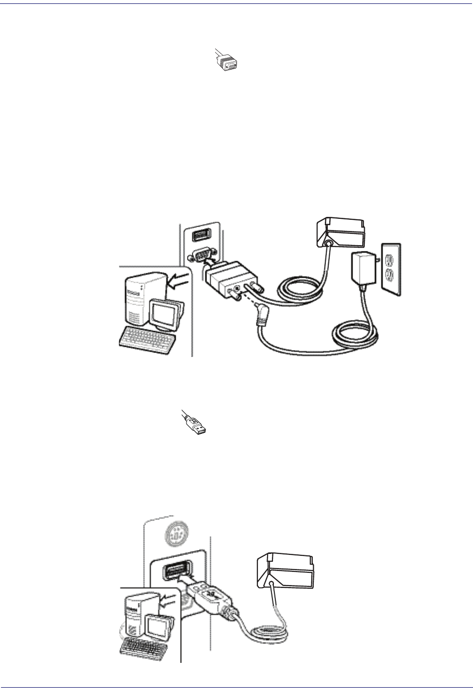
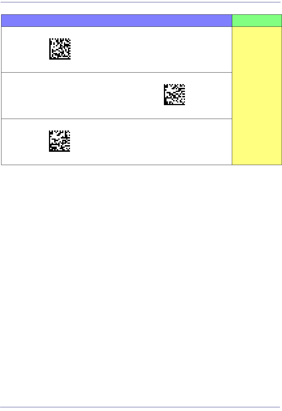
Attaching Reader to Host .............................................................................................................................................................................14
Interface Selection ....................................................................................................................................................................................... 15
Custom Configuration Settings ................................................................................................................................................................... 18
Configure Interface Settings ............................................................................................................................................................................................................18
Global Interface Features ...................................................................................................................................................................................................................18
Configuring Other Features ..............................................................................................................................................................................................................18
Software Version Transmission .......................................................................................................................................................................................................18
Resetting the Product Configuration to Defaults .....................................................................................................................................................................19
CONFIGURATION USING BAR CODES............................................................................................................................................ 21
Configuration Parameters .................................................................................................................................................................................................................21
GLOBAL INTERFACE FEATURES .................................................................................................................................................. 23
Host Commands — Obey/Ignore .............................................................................................................................................................................23
RS-232 Only Interface............................................................................................................................................................. 25
Baud Rate ...........................................................................................................................................................................................................................26
Data Bits .............................................................................................................................................................................................................................27
Stop Bits ..............................................................................................................................................................................................................................27
Parity ....................................................................................................................................................................................................................................28
Handshaking Control ....................................................................................................................................................................................................29
RS-232/USB-Com Interfaces................................................................................................................................................... 30
Intercharacter Delay .......................................................................................................................................................................................................31
Beep On ASCII BEL ..........................................................................................................................................................................................................31
Beep On Not on File .......................................................................................................................................................................................................32
ACK NAK Options ............................................................................................................................................................................................................32
ACK Character ..................................................................................................................................................................................................................33
NAK Character ..................................................................................................................................................................................................................33
ACK NAK Timeout Value ...............................................................................................................................................................................................34
ACK NAK Retry Count ....................................................................................................................................................................................................34
ACK NAK Error Handling ...............................................................................................................................................................................................35
Indicate Transmission Failure .....................................................................................................................................................................................35
Disable Character ............................................................................................................................................................................................................36
Enable Character .............................................................................................................................................................................................................36
USB Keyboard Settings .......................................................................................................................................................... 37
Country Mode ..................................................................................................................................................................................................................38
Send Control Characters ..............................................................................................................................................................................................42
Intercode Delay ...............................................................................................................................................................................................................43
Caps Lock State ................................................................................................................................................................................................................43
USB Keyboard Speed .....................................................................................................................................................................................................44
USB Keyboard Numeric Keypad ................................................................................................................................................................................45
USB-OEM Interface ................................................................................................................................................................. 47
Contents
2
Gryphon™ I GFS4400
USB-OEM Device Usage ................................................................................................................................................................................................48
Transmit Labels in Code 39 Format ..........................................................................................................................................................................49
Interface Options ............................................................................................................................................................................................................49
Data Format ............................................................................................................................................................................ 51
Global Prefix/Suffix ...................................................................................................................................................................................... 52
Global AIM ID ................................................................................................................................................................................................53
Set AIM ID Individually for GS1-128 ...............................................................................................................................................................................................55
Label ID ..........................................................................................................................................................................................................56
Label ID: Pre-Loaded Sets ..................................................................................................................................................................................................................56
Individually Set Label ID .....................................................................................................................................................................................................................57
Label ID Control ...............................................................................................................................................................................................................57
Label ID Symbology Selection − 1D Symbologies ..............................................................................................................................................58
No Read Message ............................................................................................................................................................................................................63
No Read String .................................................................................................................................................................................................................63
CODE VERIFIER ............................................................................................................................................................................ 64
Code Verifier Mode .........................................................................................................................................................................................................64
Match String .....................................................................................................................................................................................................................65
Wrong Code String .........................................................................................................................................................................................................65
Label Transmit Mode .....................................................................................................................................................................................................66
Advanced Formatting: User Label Edit ...................................................................................................................................................................66
Case Conversion ..............................................................................................................................................................................................................67
Character Conversion ....................................................................................................................................................................................................67
Digital Output ......................................................................................................................................................................... 69
Activation Event ..............................................................................................................................................................................................................70
Deactivation Event .........................................................................................................................................................................................................71
Deactivation Timeout ....................................................................................................................................................................................................71
Activation State ...............................................................................................................................................................................................................72
Reading Parameters ............................................................................................................................................................. 73
Double Read Timeout ...................................................................................................................................................................................................74
LED AND BEEPER INDICATORS ................................................................................................................................................... 75
Power On Alert .................................................................................................................................................................................................................75
Good Read: When to Indicate .....................................................................................................................................................................................75
Good Read Beep Type ...................................................................................................................................................................................................76
Good Read Beep Frequency .......................................................................................................................................................................................76
Good Read Beep Length ..............................................................................................................................................................................................77
Good Read Beep Volume .............................................................................................................................................................................................78
Good Read LED Duration .............................................................................................................................................................................................79
SCANNING FEATURES ................................................................................................................................................................. 80
Operating Mode ..............................................................................................................................................................................................................80
Phase Off Event ................................................................................................................................................................................................................81
Phase Off Timeout ..........................................................................................................................................................................................................81
Serial Start Character .....................................................................................................................................................................................................82
Serial Stop Character .....................................................................................................................................................................................................82
Presentation Mode Indication ....................................................................................................................................................................................83
Manual Trigger Control .................................................................................................................................................................................................83
Central Code Only ...........................................................................................................................................................................................................84
Illumination Off Time .....................................................................................................................................................................................................84
Illumination On Time .....................................................................................................................................................................................................85
Scanning Active Time ....................................................................................................................................................................................................85
Presentation Illumination Control ............................................................................................................................................................................86
Aiming Pointer .................................................................................................................................................................................................................86
Aiming Duration Timer .................................................................................................................................................................................................87
Green Spot Duration ......................................................................................................................................................................................................87
Mobile Phone Mode ......................................................................................................................................................................................................88
Mobile Bias ........................................................................................................................................................................................................................88
Partial Label Reading Control .....................................................................................................................................................................................89
Mirror Reading Mode ....................................................................................................................................................................................................89
Decode Negative Image ...............................................................................................................................................................................................90
Image Capture .................................................................................................................................................................................................................90
MULTIPLE LABEL READING ........................................................................................................................................................ 91
Multiple Labels per Frame ...........................................................................................................................................................................................91
Multiple Labels Ordering by Code Symbology ....................................................................................................................................................92
Contents
Product Reference Guide
3
Multiple Labels Ordering by Code Length ............................................................................................................................................................92
Symbologies ........................................................................................................................................................................... 93
1D Code Selection ........................................................................................................................................................................................ 93
DISABLE ALL SYMBOLOGIES ...................................................................................................................................................... 94
CODE EAN/UPC ............................................................................................................................................................................ 95
Coupon Control ...............................................................................................................................................................................................................95
UPC-A ..................................................................................................................................................................................................................................96
UPC-A Enable/Disable ...................................................................................................................................................................................................96
UPC-A Check Character Transmission .....................................................................................................................................................................96
Expand UPC-A to EAN-13 .............................................................................................................................................................................................97
UPC-A Number System Character Transmission .................................................................................................................................................97
UPC-A 2D Component ..................................................................................................................................................................................................98
UPC-E ............................................................................................................................................................................................98
UPC-E Enable/Disable ....................................................................................................................................................................................................98
UPC-E Check Character Transmission ......................................................................................................................................................................99
UPC-E 2D Component ...................................................................................................................................................................................................99
Expand UPC-E to EAN-13 .......................................................................................................................................................................................... 100
Expand UPC-E to UPC-A ............................................................................................................................................................................................ 100
UPC-E Number System Character Transmission ............................................................................................................................................... 101
GTIN FORMATTING ....................................................................................................................................................................101
EAN 13 (JAN 13) .........................................................................................................................................................................102
EAN 13 Enable/Disable .............................................................................................................................................................................................. 102
EAN 13 Check Character Transmission ................................................................................................................................................................ 102
EAN-13 Flag 1 Character ............................................................................................................................................................................................ 103
EAN-13 ISBN Conversion ........................................................................................................................................................................................... 103
EAN-13 2D Component ............................................................................................................................................................................................. 104
ISSN ............................................................................................................................................................................................104
ISSN Enable/Disable .................................................................................................................................................................................................... 104
EAN 8 (JAN 8) .............................................................................................................................................................................105
EAN 8 Enable/Disable ................................................................................................................................................................................................. 105
EAN 8 Check Character Transmission ................................................................................................................................................................... 105
Expand EAN 8 to EAN 13 ........................................................................................................................................................................................... 106
EAN 8 2D Component ................................................................................................................................................................................................ 106
UPC/EAN GLOBAL SETTINGS ....................................................................................................................................................107
UPC/EAN Price Weight Check .................................................................................................................................................................................. 107
UPC/EAN Quiet Zones ................................................................................................................................................................................................ 108
ADD-ONS ....................................................................................................................................................................................109
Optional Add-ons ........................................................................................................................................................................................................ 109
Optional Add-On Timer ............................................................................................................................................................................................. 110
Optional GS1-128 Add-On Timer ........................................................................................................................................................................... 113
CODE 39 ......................................................................................................................................................................................116
Code 39 Enable/Disable ............................................................................................................................................................................................ 116
Code 39 Check Character Calculation .................................................................................................................................................................. 116
Code 39 Check Character Transmission .............................................................................................................................................................. 117
Code 39 Start/Stop Character Transmission ...................................................................................................................................................... 118
Code 39 Full ASCII ........................................................................................................................................................................................................ 118
Code 39 Quiet Zones .................................................................................................................................................................................................. 119
Code 39 Length Control ............................................................................................................................................................................................ 119
Code 39 Set Length 1 ................................................................................................................................................................................................. 120
Code 39 Set Length 2 ................................................................................................................................................................................................. 121
TRIOPTIC CODE ..........................................................................................................................................................................122
Trioptic Code Enable/Disable .................................................................................................................................................................................. 122
CODE 32 (ITAL PHARMACEUTICAL CODE) ...............................................................................................................................122
Code 32 Enable/Disable ............................................................................................................................................................................................ 122
Code 32 Feature Setting Exceptions ..................................................................................................................................................................... 123
Code 32 Check Char Transmission ........................................................................................................................................................................ 123
Code 32 Start/Stop Character Transmission ...................................................................................................................................................... 123
CODE 39 CIP (FRENCH PHARMACEUTICAL) .............................................................................................................................124
Code 39 CIP Enable/Disable ..................................................................................................................................................................................... 124
CODE 39 DANISH PPT ................................................................................................................................................................124
Code 39 Danish PPT Enable/Disable ..................................................................................................................................................................... 124
CODE 39 LAPOSTE .....................................................................................................................................................................125
Contents
4
Gryphon™ I GFS4400
Code 39 LaPoste Enable/Disable ............................................................................................................................................................................ 125
CODE 39 PZN ..............................................................................................................................................................................125
Code 39 PZN Enable/Disable ................................................................................................................................................................................... 125
CODE 128 ...................................................................................................................................................................................126
Code 128 Enable/Disable .......................................................................................................................................................................................... 126
Expand Code 128 to Code 39 .................................................................................................................................................................................. 126
Code 128 Check Character Transmission ............................................................................................................................................................ 127
Code 128 Function Character Transmission ...................................................................................................................................................... 127
Code 128 Sub-Code Exchange Transmission .................................................................................................................................................... 128
Code 128 Quiet Zones ................................................................................................................................................................................................ 128
Code 128 Length Control .......................................................................................................................................................................................... 129
Code 128 Set Length 1 ............................................................................................................................................................................................... 130
Code 128 Set Length 2 ............................................................................................................................................................................................... 131
GS1-128 ......................................................................................................................................................................................132
GS1-128 Enable ............................................................................................................................................................................................................. 132
GS1-128 2D Component ........................................................................................................................................................................................... 132
CODE ISBT 128 ...........................................................................................................................................................................133
ISBT 128 Concatenation ............................................................................................................................................................................................ 133
ISBT 128 Force Concatenation ................................................................................................................................................................................ 133
ISBT 128 Concatenation Mode ................................................................................................................................................................................ 134
ISBT 128 Dynamic Concatenation Timeout ........................................................................................................................................................ 135
ISBT 128 Advanced Concatenation Options ...................................................................................................................................................... 135
INTERLEAVED 2 OF 5 (I 2 OF 5) .................................................................................................................................................136
I 2 of 5 Enable/Disable ................................................................................................................................................................................................ 136
I 2 of 5 Check Character Calculation ..................................................................................................................................................................... 137
I 2 of 5 Check Character Transmission .................................................................................................................................................................. 138
I 2 of 5 Length Control ............................................................................................................................................................................................... 138
I 2 of 5 Set Length 1 ..................................................................................................................................................................................................... 139
I 2 of 5 Set Length 2 ..................................................................................................................................................................................................... 140
INTERLEAVED 2 OF 5 CIP HR .....................................................................................................................................................141
Interleaved 2 of 5 CIP HR Enable/Disable ............................................................................................................................................................ 141
FOLLETT 2 OF 5 ..........................................................................................................................................................................141
Follett 2 of 5 Enable/Disable .................................................................................................................................................................................... 141
STANDARD 2 OF 5 .....................................................................................................................................................................142
Standard 2 of 5 Enable/Disable .............................................................................................................................................................................. 142
Standard 2 of 5 Check Character Calculation .................................................................................................................................................... 142
Standard 2 of 5 Check Character Transmission ................................................................................................................................................. 143
Standard 2 of 5 Length Control .............................................................................................................................................................................. 143
Standard 2 of 5 Set Length 1 ................................................................................................................................................................................... 144
Standard 2 of 5 Set Length 2 ................................................................................................................................................................................... 145
INDUSTRIAL 2 OF 5 ....................................................................................................................................................................146
Industrial 2 of 5 Enable/Disable .............................................................................................................................................................................. 146
Industrial 2 of 5 Check Character Calculation .................................................................................................................................................... 146
Industrial 2 of 5 Check Character Transmission ................................................................................................................................................ 147
Industrial 2 of 5 Length Control .............................................................................................................................................................................. 147
Industrial 2 of 5 Set Length 1 ................................................................................................................................................................................... 148
Industrial 2 of 5 Set Length 2 ................................................................................................................................................................................... 149
CODE IATA ..................................................................................................................................................................................150
IATA Enable/Disable ................................................................................................................................................................................................... 150
IATA Check Character Transmission ..................................................................................................................................................................... 150
CODABAR ...................................................................................................................................................................................151
Codabar Enable/Disable ............................................................................................................................................................................................ 151
Codabar Check Character Calculation .................................................................................................................................................................. 151
Codabar Check Character Transmission .............................................................................................................................................................. 152
Codabar Start/Stop Character Transmission ...................................................................................................................................................... 152
Codabar Start/Stop Character Set .......................................................................................................................................................................... 153
Codabar Start/Stop Character Match ................................................................................................................................................................... 153
Codabar Quiet Zones .................................................................................................................................................................................................. 154
Codabar Length Control ............................................................................................................................................................................................ 154
Codabar Set Length 1 ................................................................................................................................................................................................. 155
Codabar Set Length 2 ................................................................................................................................................................................................. 156
ABC CODABAR ...........................................................................................................................................................................157
Contents
Product Reference Guide
5
ABC Codabar Enable/Disable .................................................................................................................................................................................. 157
ABC Codabar Concatenation Mode ...................................................................................................................................................................... 157
ABC Codabar Dynamic Concatenation Timeout .............................................................................................................................................. 158
ABC Codabar Force Concatenation ....................................................................................................................................................................... 159
CODE 11 ......................................................................................................................................................................................160
Code 11 Enable/Disable ............................................................................................................................................................................................ 160
Code 11 Check Character Calculation .................................................................................................................................................................. 160
Code 11 Check Character Transmission .............................................................................................................................................................. 161
Code 11 Length Control ............................................................................................................................................................................................ 161
Code 11 Set Length 1 ................................................................................................................................................................................................. 162
Code 11 Set Length 2 ................................................................................................................................................................................................. 163
GS1 DATABAR™ OMNIDIRECTIONAL .......................................................................................................................................164
GS1 DataBar™ Omnidirectional Enable/Disable ............................................................................................................................................... 164
GS1 DataBar™ Omnidirectional GS1-128 Emulation ....................................................................................................................................... 164
GS1 DataBar™ Omnidirectional 2D Component .............................................................................................................................................. 165
GS1 DATABAR™ EXPANDED .....................................................................................................................................................165
GS1 DataBar™ Expanded Enable/Disable ............................................................................................................................................................ 165
GS1 DataBar™ Expanded GS1-128 Emulation ................................................................................................................................................... 166
GS1 DataBar™ Expanded 2D Component ........................................................................................................................................................... 166
GS1 DataBar™ Expanded Length Control ........................................................................................................................................................... 167
GS1 DataBar™ Expanded Set Length 1 ................................................................................................................................................................. 168
GS1 DataBar™ Expanded Set Length 2 ................................................................................................................................................................. 169
GS1 DATABAR™ LIMITED ..........................................................................................................................................................170
GS1 DataBar™ Limited Enable/Disable ................................................................................................................................................................. 170
GS1 DataBar™ Limited GS1-128 Emulation ........................................................................................................................................................ 170
GS1 DataBar™ Limited 2D Component ................................................................................................................................................................ 171
CODE 93 ......................................................................................................................................................................................171
Code 93 Enable/Disable ............................................................................................................................................................................................ 171
Code 93 Check Character Calculation .................................................................................................................................................................. 172
Code 93 Check Character Transmission .............................................................................................................................................................. 172
Code 93 Length Control ............................................................................................................................................................................................ 173
Code 93 Set Length 1 ................................................................................................................................................................................................. 174
Code 93 Set Length 2 ................................................................................................................................................................................................. 175
Code 93 Quiet Zones .................................................................................................................................................................................................. 176
MSI ..............................................................................................................................................................................................176
MSI Enable/Disable ...................................................................................................................................................................................................... 176
MSI Check Character Calculation ........................................................................................................................................................................... 177
MSI Check Character Transmission ........................................................................................................................................................................ 177
MSI Length Control ..................................................................................................................................................................................................... 178
MSI Set Length 1 .......................................................................................................................................................................................................... 179
MSI Set Length 2 .......................................................................................................................................................................................................... 180
PLESSEY ......................................................................................................................................................................................181
Plessey Enable/Disable .............................................................................................................................................................................................. 181
Plessey Check Character Calculation .................................................................................................................................................................... 181
Plessey Check Character Transmission ................................................................................................................................................................ 182
Plessey Length Control .............................................................................................................................................................................................. 182
Plessey Set Length 1 ................................................................................................................................................................................................... 183
Plessey Set Length 2 ................................................................................................................................................................................................... 184
2D Symbologies.................................................................................................................................................................... 185
2D Global Features .....................................................................................................................................................................................185
2D Maximum Decoding Time ....................................................................................................................................................................................................... 186
2D Structured Append .................................................................................................................................................................................................................... 187
2D Normal/Inverse Symbol Control ............................................................................................................................................................................................ 187
Aztec Code ..................................................................................................................................................................................................188
Aztec Code Enable / Disable .......................................................................................................................................................................................................... 188
Aztec Code Length Control ........................................................................................................................................................................................................... 188
Aztec Code Set Length 1 ........................................................................................................................................................................................... 189
Aztec Code Set Length 2 ........................................................................................................................................................................................... 190
China Sensible Code ...................................................................................................................................................................................191
China Sensible Code Enable / Disable ....................................................................................................................................................................................... 191
China Sensible Code Length Control ......................................................................................................................................................................................... 191
China Sensible Code Set Length 1 ......................................................................................................................................................................... 192
Contents
6
Gryphon™ I GFS4400
China Sensible Code Set Length 2 ......................................................................................................................................................................... 193
Data Matrix .................................................................................................................................................................................................194
Data Matrix Enable / Disable ......................................................................................................................................................................................................... 194
Data Matrix Square/Rectangular Style ....................................................................................................................................................................................... 194
Data Matrix Length Control ........................................................................................................................................................................................................... 195
Data Matrix Set Length 1 ........................................................................................................................................................................................... 195
Data Matrix Set Length 2 ........................................................................................................................................................................................... 196
Maxicode .....................................................................................................................................................................................................197
Maxicode Enable / Disable ............................................................................................................................................................................................................. 197
Maxicode Primary Message Transmission ................................................................................................................................................................................ 197
Maxicode Length Control ............................................................................................................................................................................................................... 198
Maxicode Set Length 1 .............................................................................................................................................................................................. 198
Maxicode Set Length 2 .............................................................................................................................................................................................. 199
PDF417 ........................................................................................................................................................................................................200
PDF417 Enable / Disable ................................................................................................................................................................................................................. 200
PDF417 Length Control ................................................................................................................................................................................................................... 200
PDF417 Set Length 1 .................................................................................................................................................................................................. 201
PDF417 Set Length 2 .................................................................................................................................................................................................. 202
Micro PDF417 ..............................................................................................................................................................................................203
Micro PDF417 Enable / Disable .................................................................................................................................................................................................... 203
Micro PDF417 Code 128 GS1-128 Emulation .......................................................................................................................................................................... 203
Micro PDF417 Length Control ...................................................................................................................................................................................................... 204
Micro PDF417 Set Length 1 ...................................................................................................................................................................................... 204
Micro PDF417 Set Length 2 ...................................................................................................................................................................................... 205
QR Code .......................................................................................................................................................................................................206
QR Code Enable / Disable ............................................................................................................................................................................................................... 206
QR Code Length Control ................................................................................................................................................................................................................. 206
QR Code Set Length 1 ................................................................................................................................................................................................ 207
QR Code Set Length 2 ................................................................................................................................................................................................ 208
Micro QR Code ............................................................................................................................................................................................209
Micro QR Code Enable/Disable .................................................................................................................................................................................................... 209
Micro QR Code Length Control .................................................................................................................................................................................................... 209
Micro QR Code Set Length 1 .................................................................................................................................................................................... 210
Micro QR Code Set Length 2 .................................................................................................................................................................................... 211
UCC Composite ...........................................................................................................................................................................................212
UCC Composite Enable / Disable ................................................................................................................................................................................................. 212
UCC Optional Composite Timer ................................................................................................................................................................................................... 213
Postal Code Selection .................................................................................................................................................................................214
Postnet BB Control ............................................................................................................................................................................................................................ 215
SOFTWARE CONFIGURATION STRINGS ..................................................................................................................................... 217
Command Syntax .............................................................................................................................................................................................................................. 218
SERIAL CONFIGURATION STRINGS ......................................................................................................................................................................... 220
2D CODES ...................................................................................................................................................................................242
REFERENCES................................................................................................................................................................................. 245
RS-232 Parameters .....................................................................................................................................................................................246
RS-232 Only ......................................................................................................................................................................................................................................... 246
RS-232/USB COM Parameters ....................................................................................................................................................................................................... 247
USB Intercode Delay ......................................................................................................................................................................................................................... 254
Symbologies ...............................................................................................................................................................................................255
Set Length ............................................................................................................................................................................................................................................ 255
Data Editing ................................................................................................................................................................................................256
Global Prefix/Suffix ........................................................................................................................................................................................................................... 257
Global AIM ID ...................................................................................................................................................................................................................................... 258
Label ID ................................................................................................................................................................................................................................................. 259
Character Conversion ...................................................................................................................................................................................................................... 264
Scanner Data Formatting Control ............................................................................................................................................................................................... 265
Digital Output .............................................................................................................................................................................................267
Reading Parameters ...................................................................................................................................................................................268
Double Read Timeout ...................................................................................................................................................................................................................... 268
Good Read LED Duration ................................................................................................................................................................................................................ 269
Scanning Features ......................................................................................................................................................................................270
Contents
Product Reference Guide
7
Operating Mode ................................................................................................................................................................................................................................ 270
Digital Output ..................................................................................................................................................................................................................................... 271
Scanning Active Time ...................................................................................................................................................................................................................... 272
Aiming Duration Time ..................................................................................................................................................................................................................... 273
Multiple Labels Ordering by Code Symbology ...................................................................................................................................................................... 274
TECHNICAL SPECIFICATIONS...................................................................................................................................................... 277
Imager Labeling ..........................................................................................................................................................................................282
Aiming System ................................................................................................................................................................................................................................... 282
LED and Beeper Indications .......................................................................................................................................................................283
Button and LED Status ..................................................................................................................................................................................................................... 283
Indicators .............................................................................................................................................................................................................................................. 283
Error Codes ..................................................................................................................................................................................................285
AIMER CALIBRATION................................................................................................................................................................... 287
STANDARD DEFAULTS................................................................................................................................................................ 291
Sample Bar Codes........................................................................................................................................................................ 303
KEYPAD ........................................................................................................................................................................................ 307
RESERVED CHARACTERS............................................................................................................................................................. 309
SCANCODE TABLES ..................................................................................................................................................................... 311
Control Character Emulation .....................................................................................................................................................................311
Single Press and Release Keys ....................................................................................................................................................................................................... 311
Interface Type PC AT PS/2, USB-Keyboard or USB-Keyboard for APPLE ...............................................................................................312
Interface type PC AT PS/2 Alt Mode or USB-Keyboard Alt Mode ...........................................................................................................314
Digital Interface ..........................................................................................................................................................................................316
IBM31xx 102-key ........................................................................................................................................................................................317
IBM XT ..........................................................................................................................................................................................................318
Microsoft Windows Codepage 1252 .........................................................................................................................................................319
Contents
8
Gryphon™ I GFS4400
NOTES
Product Reference Guide
9
Chapter 1
Introduction
About this Manual
This Product Reference Guide (PRG) is provided for users seeking advanced technical
information, including connection, programming, maintenance and specifications. The Quick
Reference Guide (QRG) and other publications associated with this product are downloadable
free of charge from the website listed on the back cover of this manual.
Overview
Chapter 1, (this chapter) presents information about manual conventions, and an overview of the
reader, its features and operation.
Chapter 2, Setup presents information about unpacking, cable connection information and
setting up the reader.
Chapter 3, Configuration Using Bar Codes provides instructions and bar code labels for customizing
your reader. There are different sections for interface ty
pes, general features, data formattin
g,
symbology-specific and model-specific features.
Chapter 4, Software Configuration Strings provides background information and detailed
instructions for more complex programming items.
Chapter 5, References provides background information and detailed instructions for more
complex programming items.
Appendix A, Technical Specifications lists physical and performance characteristics, as well
as
en
vironmental and regulatory specifications. It also provides standard cable pinouts and LED/
Beeper functions.
Chapter B
, Aimer Calibration describes the procedur
es for calibrating the aiming system in the scan
modules.
Appendix C, Standard Defaults references common factory default settings
for reader features and
options.
App
endix D, Sample Bar Codes offers sample bar codes for several common symbologies.
Appendix E, Keypad includes numeric bar codes to be scanned for certain parameter settings.
App
endix F, Reserved Characters provides a table of reserved characters.
Appendix G, Scancode Tables lists control character emulation information for USB Keyboard
interfaces.
Introduction References
10
Gryphon™ I GFS4400
Manual Conventions
The following conventions are used in this document:
The symbols listed below are used in this manual to not
ify the reader of key issues or procedures
that must be observed when using the reader:
Notes contain information necessary for properly diagnosing, repairing
and operating the reader.
CAUTION
The CAUTION symbol advises you of actions that could damage equip-
ment or property.
References
Current versions of this Product Reference Guide (PRG), Quick Reference Guide (QRG), the
Datalogic Aladdin™ Configuration application, and any other manuals, instruction sheets and
utilities for this product can be downloaded from the website listed below. Alternatively, printed
copies or product support CDs for most products can be purchased through your Datalogic
reseller.
Technical Support
Datalogic Website Support
The Datalogic website (www.datalogic.com) is the complete source for technical support and
information for Datalogic products. The site offers product support, warranty information,
product manuals, product tech notes, software
updates, demos, and instructions for returning
products for repair.
Reseller Technical Support
An excellent source for technical assistance and information is an authorized Datalogic reseller.
A reseller is acquainted with specific types of businesses, application software, and computer
systems and can provide individualized assistance.
Telephone Technical Support
If you do not have internet or email access, you may contact Datalogic technical support at
(541) 349-8283 or check the back cover of your manual for more contact information.
About the Reader Introduction
Product Reference Guide
11
About the Reader
The Gryphon GFS4400 is a fully self-contained standard range 2D bar code scanning module
for use in OEM applications such as self service kiosks or other semi-automated equipment
requiring the ability to read a bar code. It is intended to be an easy integration by system
designers with little expertise in scanning technology. Unlike currently available products, the
GFS4400 uses the latest and fastest imaging technology and offers Datalogic’s Green Spot for
targeting and good read feedback.
The scanning technology is essentially the same as the Gryphon
I 4400 handheld scanner family
of area imagers, with some enhancements for presentation reading and improved motion
tolerance. The enclosure is designed for ease of integration, is sealed to IP54 for cleaning, and is
constructed of a solvent- and disinfectant-tolerant resin for health care applications.
Advancements in the LED technology used in the imager-based readers significantly improve
the illumination of th
e target field of view, resulting in higher scan efficiency.
The GFS4400 is available in two different data interface versions:
Gryphon I GFS4470 Gryphon Fixed Scanner 2D Imager USB
Gryphon I GFS4450-9 Gryphon Fixed Scanner 2D Imager RS-232 9-pin connector
Programming the Reader
Configuration Methods
Programming Bar Codes
The reader is factory-configured with a standard set of default features. After scanning the
interface bar code, you can select other options and customize your reader through use of the
instructions and programming bar code labels available in the corresponding features section for
your interface. Customizable settings for many features are found in "Configuration Parameters"
starting on page 21.
Some programming labels, like "Restore Custom Defaults" on page 19, require only the scan of the
single label to enact the change. Most, however, require the r
eader to be placed in Programming
Mode prior to scanning them. Scan an ENTER/EXIT bar code once to enter Programming
Mode. Once the reader is in Programming Mode, scan a number of parameter settings before
scanning the ENTER/EXIT bar code a second time, which will then accept your changes, exit
Programming Mode and return the reader to normal operation.
There are some exceptions to the typical programming sequence described
above. Please read the description and setting instructions carefully when
configuring each programmable feature.
Introduction Programming the Reader
12
Gryphon™ I GFS4400
Datalogic Aladdin™
Programming can alternatively be performed using the Datalogic Aladdin™ Configuration
application. Aladdin™ is a multi-platform utility program providing a quick and user-friendly
configuration method via the RS-232/USB-COM interface. It communicates to the device
through a user-friendly graphical interface running on a PC. Selected configuration commands
are sent to the reader over the selected communication interface using a serial or USB cable, or
they can be printed as bar codes to be scanned.
Aladdin also provides the ability to perform a soft
ware upgrade for the connected device (see the
Datalogic Aladdin™ Help On-Line for more details).
Aladdin is available for free downlo
ad from the Datalogic website.
Software Configuration Strings
The reader can also be configured by using command strings. These strings can be sent via the
RS232/USB-COM interface using a terminal emulator such as HyperTerminal.
Refer to"Software Configuration Strings" starting on page 217 for configuration procedures using
Serial Strings sent by the Host."
Product Reference Guide
13
Chapter 2
Setup
Unpacking
Check carefully to ensure the reader and any accessories ordered are present and undamaged. If
any damage occurred during shipment, contact Datalogic Technical Support. Information is
shown on
page 10
.
KEEP THE PACKAGING. Should the unit ever require se
rvice, it should be returned in its
original shipping container.
Setting Up the Reader
Follow the steps provided in this section to connect and get your reader up and communicating
with its host.
1. Begin by connecting the scan module to the host. The correct Interface Selection will
occur auto
matically.
2. If modifications are needed, go to
Interface Selection
and set the desired interface.
3.
Configure Interface Settings
(only if not using factory settings for that interface)
4. Go to
Configuring Other Features
(if modifications are needed from factory settings)
Setup Attaching Reader to Host
14
Gryphon™ I GFS4400
Attaching Reader to Host
RS-232 Serial Connection
Turn off power to the terminal/PC and connect the reader to the terminal/PC serial port via the
RS-232 cable as shown in
Figure 1
. If the terminal will not support POT (Power Off the
Terminal) to supply reader power, use the approved power supply (AC Adapter). Plug the AC
Adapter barrel connector into th
e socket on the RS-232 cable connector and the AC Adapter
plug into a standard power outlet.
Figure 1. RS-232 Connection
USB Connection
Connect the reader to a USB port on the terminal/PC. Reference
Figure 2
.
Figure 2. USB connection
Interface Selection Setup
Product Reference Guide
15
Interface Selection
Since your scanner should have shipped with the correct interface cable (RS-232 or USB), the
interface type should already be defined. If you need to change the interface type, go to Table 1
starting on page 16
and scan the appropriate bar code in that section.
Each reader model will support one of the following sets of host interfaces:
GFS4450-9 Model GFS4470 Model
RS-232-STD
RS-232 Wincor-Nixdorf
USB-COM, USB-OEM, USB-KBD,
USB_KBD-ALT,
USB-KBD-Apple
If your installation requires you to select options to customize your reader, turn to the
appropriate
se
ction for your interface type in
"Configuration Using Bar Codes" starting on page 21
(also listed beside each interface type in
Table 1 on page 16
).
Unlike some programming features and options, interface selections
require that you scan only one programming bar code label. DO NOT
scan an ENTER/EXIT bar code prior to scanning an interface selection bar
code.
Some interfaces require the scanner to start in
the disabled state when
powered up. If additional scanner configuration is desired while in this
state, pull the trigger and hold it for five seconds. The scanner will
change to a state that allows programming with bar codes.
Setup Interface Selection
16
Gryphon™ I GFS4400
Table 1. Available Interfaces
RS-232 FEATURES
RS-232 standard interface
Select RS232-STD
Set RS-232
Interface
Features
starting on
page 25
$P,HA12,P(CR)
Select RS232-WN
RS-232 Wincor-Nixdorf
RS-232 for use with OPOS/UPOS/JavaPOS
$P,HA13,P(CR)
Select RS-232 OPOS
$P,HA47,P(CR)
Select USB-COM-STD
a
a. Download the correct USB Com driver from www.adc.datalogic.com
USB Com to simulate RS-232 standard interface
USB-OEM FEATURES
$P,HA45,P(CR)
Select USB-OEM
USB-OEM
(can be used for OPOS/UPOS/JavaPOS)
Set USB-OEM
Interface
Features
starting on
page 47
KEYBOARD FEATURES
$P,HA35,P(CR)
Select USB Keyboard
USB Keyboard with standard key encoding
Set KEYBOARD
Interface
Features
starting on page 37
USB Keyboard for Apple computers
$P,HA2C,P(CR)
Select USB-KBD-APPLE
$P,HA2B,P(CR)
Select USB Alternate Keyboard
USB Keyboard with alternate key encoding
Interface Selection Setup
Product Reference Guide
17
Setup Custom Configuration Settings
18
Gryphon™ I GFS4400
Custom Configuration Settings
Configure Interface Settings
If your installation requires you to select options to customize your reader, turn to the
appropriate section for your interface type in
"Configuration Using Bar Codes" starting on page 21
.
"RS-232 Only Interface" on page 25
"RS-232/USB-Com Interfaces" on page 30
"USB Keyboard Settings" on page 37
Global Interface Features
See "
Global Interface Features" on page 23
for settings configurable by all interface types.
Configuring Other Features
If your installation requires different programming than the standard factory default settings,
the following sections of this manual allow configuration of non-interface-specific settings you
might require:
Reading Parameters
:
Reading Parameters include programming for scanning, beeper and LED
indicators and other universal settings.
Symbologies
:
Includes options concerning the bar code label types (symbologies). These settings
allow you to enable/disable symbologies, set label lengths, require check digit, etc.
Software Version Transmission
The software version of the device can be transmitted over the interface by scanning the
following label.
Custom Configuration Settings Setup
Product Reference Guide
19
Resetting the Product Configuration to Defaults
Restore Custom Defaults
If you aren’t sure what programming options are in your imager, or you’ve changed some
options and want to restore the Custom Default Configuration that may have been saved in the
scanner, scan the Restore Custom Default Configuration bar code below. This will restore the
custom configuration for the currently active interface.
Custom defaults are based on the interface type. Configure the imager
for the correct interface before scanning this label.
Restore Factory Configuration
If you want to restore the Factory Configuration for your imager, scan either the Restore USA
Factory Configuration bar code or the Restore EU Factory Configuration bar code below. Both
labels restore the scanner configuration to the factory settings, including the interface type. The
USA label restores Label IDs to those historically used in the USA. The EU label restores Label
IDs to those historically used in Europe. The Label ID sets for USA and EU are shown in the
“Label ID Control” section on page 57
of this manual.
$P,AE,P(CR)
Restore USA Factory Configuration
$P,Ae,P(CR)
Restore EU Factory Configuration
The programming items listed in the following sections show the factory default settings for
each of the menu commands.
Setup Custom Configuration Settings
20
Gryphon™ I GFS4400
NOTES
Product Reference Guide
21
Chapter 3
Configuration Using Bar Codes
This and following sections provide programming bar codes to configure your reader by
changing the default settings. For details about additional methods of programming, see
"Configuration Methods" on page 11.
You must first enable your reader to read bar codes in order to use this
section. If you have not done this, go to
Setup, starting on page 13
and
complete the appropriate procedure.
Configuration Parameters
Once the reader is set up, you can change the default parameters to meet your application needs.
Refer to "Standard Defaults" starting on page 291 for initial configuration in order to set the
default values and select the interface for your application.
The following configuration parameters are divided into logical groups, making it easy to find
the
desired function based on its reference group.
Interface Configuration:
"Global Interface Features" on page 23
"RS-232 Only Interface" on page 25
"RS-232/USB-Com Interfaces" on page 30
"USB Keyboard Settings" on page 37
"USB-OEM Interface" on page 47
Parameters common to all interface applications:
"Data Format" on page 51 gives options to control the messages sent to the Host system.
"Reading Parameters" on page 73 control various operating modes and indicators status
functioning.
Symbology-specific parameters:
"Symbologies" on page 93 provides configuration of a personalized mix of 1D codes, code
families and their options.
"2D Symbologies" on page 185 provides configuration of a personalized mix of 2D codes,
code families and their options.
You must first enable your reader to read bar codes in order to use this
section. If you have not done this, go to
Setup, starting on page 13
and
complete the appropriate procedure.
Enter/Exit Programming Mode
22
Gryphon™ I GFS4400
To program features:
1. Scan the ENTER/EXIT PROGRAMMING bar code, available at the top of each pro-
gramming page, when applicable.
2. Scan the bar code to set the desired programming feature. You may need to cover unused
bar codes on the page, and possibly the facing page,
to ensure that the reader reads only
the bar code you intend to scan.
3. If additional input parameters are needed, go to Appendix E, Keypad, and scan the appro-
priate characters from the keypad.
Additional information about many features can be found in the “Refer-
ences” chapter.
If you make a mistake before the last character, scan the CANCEL bar code
to
ab
ort and not save the entry string. You can then start again at the
beginning.
4. Complete the programming sequence by scanning the ENTER/EXIT PROGRAM-
MING bar code to exit Programming Mode.
For more detailed descriptions, programming information and examples
for setting selected
configuration items,
see References, starting on page 245.
Enter/Exit Programming Mode
Product Reference Guide
23
GLOBAL INTERFACE FEATURES
The following interface features are configurable by all interface types.
Host Commands — Obey/Ignore
This option specifies whether the reader will obey or ignore host commands. When set to
ignore, the reader will ignore all host commands except for those necessary for:
•service mode
flash programming mode
keeping the interface active
transmission of labels.
DEFAULT
$CIFIH00(CR)
Host Commands = Obey
(Do Not Ignore Host Commands)
$CIFIH01(CR)
Host Commands = Ignore
Enter/Exit Programming Mode
24
Gryphon™ I GFS4400
NOTES
Product Reference Guide
25
RS-232 ONLY INTERFACE
BAUD RATE on page 26
DATA BITS on page 27
STOP BITS on page 27
PARITY on page 28
HANDSHAKING CONTROL on page 29
Use the programming bar codes in this section if modifica
tions to the standard RS-232
interface settings are necessary to meet your system’s requirements. Additional settings
which apply to both the RS-232 and USB interfaces are available in the next section, "RS-
232/USB-Com Interfaces" starting on page 30.
Reference Appendix C, Standard Defaults for a listing of standard factory settings.
Enter/Exit Programming Mode RS-232 Only Interface
26
Gryphon™ I GFS4400
Baud Rate
See page 246 for information on this feature.
$CR2BA00(CR)
Baud Rate = 1200
$CR2BA01(CR)
Baud Rate = 2400
$CR2BA02(CR)
Baud Rate = 4800
$CR2BA03(CR)
Baud Rate = 9600
DEFAULT
$CR2BA04(CR)
Baud Rate = 19,200
$CR2BA05(CR)
Baud Rate = 38,400
$CR2BA06(CR)
Baud Rate = 57,600
$CR2BA07(CR)
Baud Rate = 115,200
RS-232 Only Interface Enter/Exit Programming Mode
Product Reference Guide
27
Data Bits
This parameter allows the reader to interface with devices requiring a 7-bit or 8-bit ASCII
protocol for sending and receiving data.
$CR2DA00(CR)
7 Data Bits
$CR2DA01(CR)
8 Data Bits
DEFAULT
Stop Bits
Set the number of stop bits to match host device requirements. See page 246 for more
information on this feature.
DEFAULT
$CR2ST00(CR)
1 Stop Bit
$CR2ST01(CR)
2 Stop Bits
Enter/Exit Programming Mode RS-232 Only Interface
28
Gryphon™ I GFS4400
Parity
This feature specifies parity required for sending and receiving data. Select the parity type
according to host device requirements. See page 246 for more information.
DEFAULT
$CR2PA00(CR)
Parity = None
$CR2PA01(CR)
Parity = Even
$CR2PA02(CR)
Parity = Odd
RS-232 Only Interface Enter/Exit Programming Mode
Product Reference Guide
29
Handshaking Control
DEFAULT
$CR2HC00(CR)
Handshaking Control = RTS
$CR2HC01(CR)
Handshaking Control = RTS/CTS
$CR2HC02(CR)
Handshaking Control = RTS/XON/XOFF
$CR2HC03(CR)
Handshaking Control = RTS On/CTS
$CR2HC04(CR)
Handshaking Control = RTS/CTS Scan Control
See page 246 for more information about this feature.
Product Reference Guide
30
RS-232/USB-COM INTERFACES
INTERCHARACTER DELAY on page 31
BEEP ON ASCII BEL on page 31
BEEP ON NOT ON FILE on page 32
ACK NAK OPTIONS on page 32
ACK CHARACTER on page 33
NAK CHARACTER on page 33
ACK NAK TIMEOUT VALUE on page 34
ACK NAK RETRY COUNT on page 34
ACK NAK ERROR HANDLING on page 35
INDICATE TRANSMISSION FAILURE on page 35
DISABLE CHARACTER on page 36
ENABLE CHARACTER on page 36
The programming bar codes in this chapter allow modifications t
o the standard RS-232 and
USB-Com interfaces. Reference Appendix C, Standard Defaults for a listing of standard factory
settings.
RS-232/USB-Com Interfaces Enter/Exit Programming Mode
Product Reference Guide
31
Intercharacter Delay
This parameter specifies the intercharacter delay between the end of one character and the
beginning of the next. The delay can be set within a range of zero (0) to 990 milliseconds in
10ms increments. A setting of zero specifies no delay.
$CR2IC00(CR)
Intercharacter Delay = No Delay
$CR2IC
Select Intercharacter Delay Setting
To configure this feature, scan the ENTER/EXIT
PROGRAMMING MODE bar code above, then the
bar code at left followed by the digits from the
Alphanumeric characters in Appendix E, Keypad
representing your desired character(s). End by
scanning the ENTER/EXIT b
ar code again.
Make a mistake? Scan the CANCEL bar code to abort
and not save the entry string. You can then start again at
the beginning.
~
CANCEL
DEFAULT
00 = No Intercharacter Delay
Beep On ASCII BEL
When this parameter is enabled, the reader issues a beep when a <BEL> character is detected on
the RS-232 serial line. <BEL> is issued to gain a user's attention to an illegal entry or other
important event.
$CR2BB00(CR)
Beep On ASCII BEL = Disable
DEFAULT
$CR2BB01(CR)
Beep On ASCII BEL = Enable
Enter/Exit Programming Mode RS-232/USB-Com Interfaces
32
Gryphon™ I GFS4400
Beep On Not on File
This option enables/disables the action of the reader to sound a three beep sequence upon
receiving a Not-On-File (NOF) host command.
$CBPNF00(CR)
Beep On Not On File = Disable
DEFAULT
$CBPNF01(CR)
Beep On Not On File = Enable
ACK NAK Options
This enables/disables the ability of the reader to support the RS-232 ACK/NAK protocol.
See page 248 for more information.
DEFAULT
$CR2AE00(CR)
ACK/NAK Protocol = Disable ACK/NAK
$CR2AE01(CR)
ACK/NAK Protocol = Enable for label transmission
$CR2AE02(CR)
ACK/NAK Protocol = Enable for host-command
acknowledge
$CR2AE03(CR)
ACK/NAK Protocol = Enable for label transmission and
host-command acknowledge
RS-232/USB-Com Interfaces Enter/Exit Programming Mode
Product Reference Guide
33
ACK Character
This setting specifies an ASCII character or hex value to be used as the ACK character. ASCII
characters or any hex value from 0 to 0xFF can be selected. See page 248 for more information.
$CR2AC
Select ACK Character Setting
DEFAULT
0x06 ‘ACK’ Character
Setting to previously defined characters such as XON, XOFF, or host commands conflicts with normal
operation of these characters. 8-bit data is not recognized when the option
Data Bits
has been set as
7 Data Bits.
NAK Character
This setting specifies an ASCII character or hex value to be used as the NAK character. ASCII
characters or any hex value from 0 to 0xFF can be selected.
Setting to previously defined characters such as XON, XOFF, or host commands conflicts with normal
operation of these characters. 8-bit data is not recognized when the option
Data Bits
has been set as
7 Data Bits.
See page 249 for more information.
$CR2NA
Select NAK Character Setting
DEFAULT
0x15 ‘NAK’ Character
Enter/Exit Programming Mode RS-232/USB-Com Interfaces
34
Gryphon™ I GFS4400
ACK NAK Timeout Value
This option specifies the amount of time the reader waits for an ACK character from the host
following label transmission. The selectable timeout range is 200 milliseconds to 15,000ms (15
seconds) in 200ms increments. A selection of 0 disables the timeout.
See page 250 for more information on setting this feat
ure.
$CR2AT
Select ACK NAK Timeout Value Setting
To configure this feature, scan the ENTER/EXIT
PROGRAMMING MODE bar code above, then the
bar code at left followed by the digits from the
Alphanumeric characters in Appendix E, Keypad
representing your desired character(s). End by
scanning the ENTER/EXIT b
ar code again.
Make a mistake? Scan the CANCEL bar code to
abort and
not save the entry string. You can then start again at the
beginning.
~
CANCEL
DEFAULT
01 ACK NAK Timeout value is 200ms
ACK NAK Retry Count
This feature specifies the number of times the reader retries a label transmission due to a retry
condition. The selectable range is from 1 to 254 retries. A selection of 0 disables the count, and
a selection of 255 specifies unlimited retries. See page 251 for more information.
$CR2AR
Select ACK NAK Retry Count Setting
To configure this feature, scan the ENTER/EXIT
PROGRAMMING MODE bar code above, then the
bar code at left followed by the digits from the
Alphanumeric characters in Appendix E, Keypad
representing your desired character(s). End by
scanning the ENTER/EXIT b
ar code again.
Make a mistake? Scan the CANCEL bar code to
abort and
not save the entry string. You can then start again at the
beginning.
~
CANCEL
DEFAULT
003 = 3 Retries
RS-232/USB-Com Interfaces Enter/Exit Programming Mode
Product Reference Guide
35
ACK NAK Error Handling
This feature specifies the method the reader uses to handle receive errors detected while waiting
for an ACK character from the host.
DEFAULT
$CR2EH00(CR)
ACK NAK Error Handling = Ignore Errors Detected
$CR2EH01(CR)
ACK NAK Error Handling = Process Error as Valid ACK
Character
$CR2EH02(CR)
ACK NAK Error Handling = Process Error as
Valid NAK Character
Indicate Transmission Failure
This option enables/disables the reader’s ability to sound an error beep to indicate a
transmission failure while in ACK/NAK mode
$CR2TF00(CR)
Indicate Transmission Failure = Disable Indication
$CR2TF01(CR)
Indicate Transmission Failure = Enable Indication
DEFAULT
.
Enter/Exit Programming Mode RS-232/USB-Com Interfaces
36
Gryphon™ I GFS4400
Disable Character
Specifies the value of the RS-232 host command used to disable the reader.
ASCII characters or any hex value from 0 to 0xF
F can be selected.
Setting to previously defined characters such as XON, XOFF, or host commands conflicts with
normal operation of these characters. 8-bit data is not recognized when the option
Data Bits
has been set as 7 Data Bits.
See page 252 for more information on setting this feature.
$CR2DC
Select Disable Character Setting
DEFAULT
0x44 = Disable Character is ‘D’
Enable Character
Specifies the value of the RS-232 host command used to enable the reader.
ASCII characters or any hex value from 0 to 0xF
F can be selected.
Setting to previously defined characters such as XON, XOFF, or host commands conflicts with
normal operation of these characters. 8-bit data is not recognized when the option
Data Bits
has been set as 7 Data Bits.
See page 253 in “References” for more information on setting this feature.
$CR2EC
Select Enable Character Setting
DEFAULT
0x45 = Enable Character is ‘E’
Product Reference Guide
37
USB KEYBOARD SETTINGS
COUNTRY MODE on page 38
SEND CONTROL CHARACTERS on page 42
INTERCODE DELAY on page 43
CAPS LOCK STATE on page 43
USB KEYBOARD SPEED on page 44
USB KEYBOARD NUMERIC KEYPAD on page 45
Use the programming bar codes in this chapter to select options for USB Keyboard
Interface. Reference Appendix C, Standard Defaults for a listing of standard factory
settings.
Information about control character emulation which applies to keyboard interfaces is
listed in Ap
pendix G, Scancode Tables.
Enter/Exit Programming Mode USB Keyboard Settings
38
Gryphon™ I GFS4400
Country Mode
This feature specifies the country/language supported by the keyboard. Several languages are
supported:
DEFAULT
$CKBCO00(CR)
Country Mode = U.S.
$CKBCO01(CR)
Country Mode = Belgium
$CKBCO02(CR)
Country Mode = Britain
$CKBCO11(CR)
Country Mode = Croatia
Supports only the interfaces listed in the Country
Mode feature description.
Supports only the interfaces listed in the Country
Mode
feature description.
$CKBCO0E(CR)
Country Mode = Czech Republic
$CKBCO03(CR)
Country Mode = Denmark
Supports only the interfaces listed in the Country Mode
feature description.
USB Keyboard Settings Enter/Exit Programming Mode
Product Reference Guide
39
Country Mode (continued)
$CKBCO04(CR)
Country Mode = France
Supports only the interfaces listed in the Country Mode fea-
ture description.
$CKBCO13(CR)
Country Mode = French Canadian
$CKBCO05(CR)
Country Mode = Germany
Supports only the interfaces listed in the Country Mode fea-
ture description.
$CKBCO0D(CR)
Country Mode = Hungary
$CKBCO06(CR)
Country Mode = Italy
Supports only the interfaces listed in the Country Mode fea-
ture description.
$CKBCO0C(CR)
Country Mode = Japanese 106-key
Enter/Exit Programming Mode USB Keyboard Settings
40
Gryphon™ I GFS4400
Country Mode (continued)
$CKBCO14(CR)
Country Mode = Lithuanian
Supports only the interfaces listed in the Country Mode
fea
ture description.
$CKBCO07(CR)
Country Mode = Norway
$CKBCO12(CR)
Country Mode = Poland
Supports only the interfaces listed in the Country Mode
feature description.
Supports only the interfaces listed in the Country Mode fea-
ture description.
$CKBCO08(CR)
Country Mode = Portugal
$CKBCO10(CR)
Country Mode = Romania
Supports only the interfaces listed in the Country
Mode fe
ature description.
Supports only the interfaces listed in the Country Mode fea-
ture description.
$CKBCO0F(CR)
Country Mode = Slovakia
USB Keyboard Settings Enter/Exit Programming Mode
Product Reference Guide
41
Country Mode (continued)
$CKBCO09(CR)
Country Mode = Spain
$KBCO0A(CR)
Country Mode = Sweden
$CKBCO0B(CR)
Country Mode = Switzerland
Supports only the interfaces listed in the Country
Mode feature description.
Enter/Exit Programming Mode USB Keyboard Settings
42
Gryphon™ I GFS4400
Send Control Characters
This feature specifies how the reader transmits ASCII control characters to the host. Reference
Appendix G, Scancode Tables for more information about control characters.
Options are as follows:
Control Character 00 :
Characters from 00 to 0x1F are sent as control character Ctrl+Keys,
special keys are located from 0x80 to 0xA1.
Control Character 01 :
Characters from 00 to 0x1F are sent as control character Ctrl+Shift,
special keys are located from 0x80 to 0xA1.
Control Character 02 :
Special keys are located from 00 to 0x1F and characters from 0x80 to
0xFE are intended as an extended ASCII table (see "Microsoft Windows Codepage 1252" on
page 319).
DEFAULT
$CKBSC00(CR)
Reader Send Control Characters = 00
$CKBSC01(CR)
Reader Send Control Characters = 01
$CKBSC02(CR)
Reader Send Control Characters = 02
USB Keyboard Settings Enter/Exit Programming Mode
Product Reference Guide
43
Intercode Delay
Specifies the delay between labels transmitted to the host for this interface. The selectable range
for this feature is from 0 to 99 seconds.
See page 254 in “References” for detailed information and examples for setting this feature.
$CKBID
Set Intercode Delay
To configure this feature, scan the ENTER/EXIT PROGRAM-
MING MODE bar code above, then the bar code at left fol-
lowed by the digits from the Alphanumeric characters in
Appendix E, Keypad representing your desired charac-
ter(s). End by scanning the ENTER/EXIT bar code again.
Make a mistake? Scan the CANCEL bar code to
abort and
not save the entry string. You can then start again at the
beginning.
~
CANCEL
DEFAULT
00 = No Intercode Delay
Caps Lock State
This option specifies the format in which the reader sends character data. This does not apply
when an alternate key encoding keyboard is selected.
DEFAULT
$CKBCL00(CR)
Caps Lock State = Caps Lock OFF
$CKBCL01(CR)
Caps Lock State = Caps Lock ON
$CKBCL02(CR)
Caps Lock State = AUTO Caps Lock Enable
Enter/Exit Programming Mode USB Keyboard Settings
44
Gryphon™ I GFS4400
USB Keyboard Speed
This option specifies the USB poll rate for a USB keyboard.
DEFAULT
$CKBSP01(CR)
USB Keyboard Speed = 1ms
$CKBSP02(CR)
USB Keyboard Speed = 2ms
$CKBSP03(CR)
USB Keyboard Speed = 3ms
$CKBSP04(CR)
USB Keyboard Speed = 4ms
$CKBSP05(CR)
USB Keyboard Speed = 5ms
$CKBSP06(CR)
USB Keyboard Speed = 6ms
This feature applies ONLY to the USB Keyboard interface.
$CKBSP07(CR)
USB Keyboard Speed = 7ms
$CKBSP08(CR)
USB Keyboard Speed = 8ms
$CKBSP09(CR)
USB Keyboard Speed = 9ms
$CKBSP0A(CR)
USB Keyboard Speed = 10ms
USB Keyboard Settings Enter/Exit Programming Mode
Product Reference Guide
45
USB Keyboard Speed (continued)
USB Keyboard Numeric Keypad
This option Controls whether numeric characters will be sent using standard keys or the
numeric keypad.
DEFAULT
$CKBKP00(CR)
Standard Keys
$CKBKP01(CR)
Numeric Keypad
Enter/Exit Programming Mode USB Keyboard Settings
46
Gryphon™ I GFS4400
NOTES
Product Reference Guide
47
USB-OEM INTERFACE
USB-OEM DEVICE USAGE on page 48
TRANSMIT LABELS IN CODE 39 FORMAT on page 49
INTERFACE OPTIONS on page 49
Feature settings for USB interfaces differ depending upon which host type the reader will be
connected with. Use the feature
settings in this chapter to specifically configure for the USB-
OEM interface. Other USB interfaces are included in the appropriate chapter for their host
type.
Reference Appendix C for a listing of standard factory settings.
Enter/Exit Programming Mode USB-OEM Interface
48
Gryphon™ I GFS4400
USB-OEM Device Usage
The USB-OEM protocol allows for the reader to be identified as one of two different types of
bar code scanners. Depending on what other scanners you may already have connected to a
USB-OEM POS, you may need to change this setting to enable all devices to communicate.
Options are:
Table Top Scanner
Handheld Scanner
$CIBUT00(CR)
USB-OEM Device Usage = Table Top Scanner
$CIBUT01(CR)
USB-OEM Device Usage = Handheld Scanner
DEFAULT
It may be necessary to switch device usage when connecting two readers/scanners of the same
type to a POS system.
USB-OEM Interface
Product Reference Guide
49
Transmit Labels in Code 39 Format
This feature enable/disables translation to Code 39 before transmitting label data to a USB-
OEM host. Only the symbology identifier is modified for the translation. The data is not
converted to Code 39 or verified to be valid for Code 39.
Options are:
Code 39 Format:
Translate the following symbologies to Code 39:
USB-OEM: Code128, Code 93, and Codabar
DEFAULT
$CIBC300(CR)
Transmit Labels in Code 39 Format =
IBM Standard Format
$CIBC301(CR)
Transmit Labels in Code 39 Format = Code 39 Format
Interface Options
$CIFO101(CR)
Obey Scanner Configuration Host Commands
$CIFO102(CR)
Ignore Scanner Configuration Host Commands
DEFAULT
This feature provides for an interface-specific control mechanism.
USB-OEM Interface
50
Gryphon™ I GFS4400
NOTES
Product Reference Guide
51
DATA FORMAT
GLOBAL PREFIX/SUFFIX on page 52
GLOBAL AIM ID on page 53
SET AIM ID INDIVIDUALLY FOR GS1-128 on page 55
LABEL ID starting on page 56
Label ID: Pre-Loaded Sets
Individually Set Label ID
Label ID Control
Label ID Symbology Selection • 1D Symbologies
Label ID Symbology Selection • 2D Symbologies
NO READ MESSAGE starting on page 63
NO READ STRING starting on page 63
CODE VERIFIER MODE starting on page 64
Code Verifier Mode
Match String
Wrong Code String
CASE CONVERSION on page 67
CHARACTER CONVERSION on page 67
The features in this chapter can be used to build specific user-defined data in
to a message
string. See “References” starting on page 256 for more detailed instructions on setting these
features.
Reference Appendix C for a listing of standard factory settings.
Enter/Exit Programming Mode Data Format
52
Gryphon™ I GFS4400
Global Prefix/Suffix
This option sets up to 20 characters each from the set of ASCII characters or any hex value from
00 to FF. The characters may be added as a prefix (in a position before the bar code data, also
called a header) and/or as a suffix (in a position following the bar code data, also called a footer).
See page 257 for more detailed instructions on setting this feat
ure.
To configure this feature, scan the ENTER/EXIT PROGRAMMING MODE bar code above
to place
the unit in Programming Mode, then the “Set Global Prefix” or “Set Global Suffix,”
bar code followed by the digits (in hex) from the Alphanumeric characters in Appendix E
Keypad representing your desired character(s). If le
ss than the expected string of 20 characters
are selected, scan the ENTER/EXIT bar code to terminate the st
ring. Exit programming mode
by scanning the ENTER/EXIT bar code again.
$CLFPR
Set Global Prefix
$CLFSU
Set Global Suffix
Make a mistake? Scan the CANCEL bar code to abort and not
save the entry string. You can then start again at the begin-
ning.
~
CANCEL
DEFAULT
No Global Prefix
Global Suffix = 0x0D (CR)
Data Format Enter/Exit Programming Mode
Product Reference Guide
53
Global AIM ID
This feature enables/disables addition of AIM IDs for all symbology
types.
AIM label identifiers (as opposed to custom characters you select yourself as with label
identifiers) can be included with scanned bar code data. See Table 2 on page 3-53 for a listing of
AIM IDs.
AIM label identifiers consist of three characters as follows:
A close brace character (ASCII ‘]’), followed by...
A code character (see some samples in the table below), followed by...
A modifier character (the modifier character is symbol dependent).
DEFAULT
$CAIEN00(CR)
Global AIM ID = Disable
$CAIEN01(CR)
Global AIM ID = Enable
Table 2
. AIM IDs
Tag Name
AIM ID code
character
AIM ID code
ASCII value
ABC CODABAR X 58
ANKER PLESSEY N 4E
AZTEC z 7A
CHINA SENSIBLE CODE X 58
CODABAR F 46
CODE11 H 48
CODE128 C 43
CODE32 A 41
CODE39 A 41
CODE39 CIP X 58
CODE39 DANISH PPT X 58
CODE39 LAPOSTE X 58
CODE39 PZN X 58
CODE93 G 47
DATABAR 14 e 65
DATABAR 14 COMPOSITE e 65
DATABAR EXPANDED e 65
Enter/Exit Programming Mode Data Format
54
Gryphon™ I GFS4400
DATABAR EXPANDED
COMPOSITE e 65
DATABAR LIMITED e 65
DATABAR LIMITED COMPOSITE e 65
DATA MATRIX d 64
EAN128 C 43
EAN128 COMPOSITE C 43
EAN13 E 45
EAN13 P2 E 45
EAN13 P5 E 45
EAN13 COMPOSITE E 45
EAN8 E 45
EAN8 P2 E 45
EAN8 P5 E 45
EAN8 COMPOSITE E 45
FOLLET 2OF5 X 58
I2OF5 I 49
IATA INDUSTRIAL 2OF5 X 58
INDUSTRIAL 2OF5 X 58
ISBN X 58
ISBT128 CONCAT X 58
ISSN X 58
MAXICODE U 55
MICRO QR Q 51
MICRO PDF L 4C
MSI M 4D
PDF417 L 4C
PLESSEY P 50
POSTAL AUSTRALIAN X 58
POSTAL IMB X 58
POSTAL JAPANESE X 58
POSTAL KIX X 58
POSTAL PLANET X 58
POSTAL PORTUGAL X 58
POSTAL POSTNET BB X 58
POSTAL ROYAL MAIL X 58
POSTAL SWEDISH X 58
POSTNET X 58
QR CODE Q 51
S25 S 53
TRIOPTIC X 58
UPCA E 45
UPCA P2 E 45
UPCA P5 E 45
UPCA COMPOSITE E 45
UPCE E 45
UPCE P2 E 45
UPCE P5 E 45
UPCE COMPOSITE E 45
Data Format Enter/Exit Programming Mode
Product Reference Guide
55
Set AIM ID Individually for GS1-128
This feature configures a Label ID individually for the GS1-128 symbology and the
programming for this works the same way as Label ID. See Label ID: Set Individually Per
Symbology, starting on page 262 for detailed instructions on sett
ing this feature.
$CU8AI00(CR)
Set AIM ID Individually for GS1-128 = Disable
$CU8AI01(CR)
Set AIM ID Individually for GS1-128 = Enable
DEFAULT
Data Format
56
Gryphon™ I GFS4400
Label ID
A Label ID is a customizable code of up to three ASCII characters (convert to Hex using the
ASCII Chart on the inside back cover of this manual), used to identify a bar code symbology
type. It can be appended previous to or following the transmitted bar code data depending upon
how this option is enabled. This feature provides options for configuring custom Label IDs or
individually per symbology (see "Individually Set Label ID" on page 57). If you wish to
program the reader to always include an industry standard label identifier for ALL symbology
types, se
e the previous feature "Global AIM ID" on page 53.
See Label ID, starting on page 259 of “References” for more information on setting this feature.
Label ID: Pre-Loaded Sets
The reader supports two pre-loaded sets of Label IDs. See Label ID: Pre-loaded Sets, starting on
page 259 for details on the USA set and EU set.
CAUTION
DEFAULT
$P,AE,P\r
Label ID Pre-loaded Set = USA Set
$P,Ae,P\r
Label ID Pre-loaded Set = EU Set
When changing from one Label ID set to another, all other reader configuration
settings, including the host interface type, will be erased and set to the stan-
dard factory defaults. Any custom configuration or custom defaults will be lost.
Unlike some programming features and options, th
is feature requires that you
scan only one programming bar code label. DO NOT scan an ENTER/EXIT bar
code prior to scanning the bar codes below.
Data Format Enter/Exit Programming Mode
Product Reference Guide
57
Individually Set Label ID
This feature configures a Label ID individually for a single symbology. To set, first define
whether you want it as a prefix or suffix by scanning a label below. Then turn to Label ID
Symbology Selection • 1D Symbologies, starting on page 58 to select the symbology you want
to set, followed by up to 3 characters from the ASCII Chart at the bac
k of this manual. See
"Label ID: Set Individually Per Symbology" on page 262 fo
r detailed instructions on setting this
feature.
Label ID Control
This option controls whether a Label ID is disabled, or sent as a prefix or suffix for a given
symbology type.
DEFAULT
$CIDCO00(CR)
Label ID Transmission = Disable
$CIDCO01(CR)
Label ID Transmission = Enable as Prefix
$CIDCO02(CR)
Label ID Transmission = Enable as Suffix
Enter/Exit Programming Mode Data Format
58
Gryphon™ I GFS4400
Label ID Symbology Selection 1D Symbologies
This option selects the symbology for which a Label ID is to be configured. See "Label ID" on
page 56 or page 262 in “References” for more detailed instructions.
$CACID
If less than the expected string of 3 characters are selected, scan the ENTER/
EXIT bar code twice to accept the selection and exit Programming Mode.
Set ABC Codabar Label ID Character(s)
$CP3ID
Set Code 32 Pharmacode Label ID Character(s)
$CALID
Set Anker Plessey Label ID Character(s)
$CC9ID
Set Code 93 Label ID Character(s)
$CPAID
Set Australian Postal Code Label ID Character(s)
$CI8ID
Set Concatenated ISBT 128 Label ID Character(s)
$CCBID
Set Codabar Label ID Character(s)
$CDPID
Set Danish PPT Label ID Character(s)
$CC1ID
Set Code 11 Label ID Character(s)
$C3BID
Set EAN 13 Label ID Character(s)
$CC8ID
Set Code 128 Label ID Character(s)
$C3MID
Set EAN 13 Composite Label ID Character(s)
$CC3ID
Set Code 39 Label ID Character(s)
$C32ID
Set EAN 13 P2 Label ID Character(s)
Data Format Enter/Exit Programming Mode
Product Reference Guide
59
Label ID Symbology Selection − 1D Symbologies (continued)
$CCCID
Set Code 39 CIP Label ID Character(s)
$C35ID
Set EAN 13 P5 Label ID Character(s)
$C8BID
Set EAN 8 Label ID Character(s)
$CXCID
Set GS1 DataBar Expanded Composite
Label ID Character(s)
$C8MID
Set EAN 8 Composite Label ID Character(s)
$CU8ID
Set GS1-128 Label ID Character(s)
$C82ID
Set EAN 8 P2 Label ID Character(s)
$CUMID
Set GS1-128 Composite Label ID Character(s)
$C85ID
Set EAN 8 P5 Label ID Character(s)
$CLBID
Set GSI DataBar Limited Label ID Character(s)
$CF2ID
Set Follett 2 of 5 Label ID Character(s)
$CLCID
GSI DataBar Limited Composite Label ID Character(s)
$C4BID
Set GS1 DataBar 14 Label ID Character(s)
$CG2ID
Set GTIN 2 Label ID Character(s)
$C4CID
Set GS1 DataBar 14 Composite Label ID Character(s)
$CG5ID
Set GTIN 5 Label ID Character(s)
Enter/Exit Programming Mode Data Format
60
Gryphon™ I GFS4400
Label ID Symbology Selection − 1D Symbologies (continued)
$CXBID
Set GS1 DataBar Expanded Label ID Character(s)
$CGBID
Set GTIN 8 Label ID Character(s)
$CIAID
Set IATA Industrial 2 of 5 Label ID Character(s)
$CLPID
Set LaPoste Code 39 Label ID Character(s)
$CPMID
Set IMB Postal Code Label ID Character(s)
$CMSID
Set MSI Label ID Character(s)
$CU2ID
Set Industrial 2 of 5 Label ID Character(s)
$CPPID
Set Planet Postal Code Label ID Character(s)
$CI2ID
Set Interleaved 2 of 5 Label ID Character(s)
$CPLID
Set Plessey Label ID Character(s)
$CISID
Set ISBN Label ID Character(s)
$CPGID
Set Portugal Postal Code Label ID Character(s)
$CINID
Set ISSN Label ID Character(s)
$CPNID
Set Postnet Label ID Character(s)
$CPJID
Set Japan Postal Code Label ID Character(s)
$CPKID
Set Kix Postal Code Label ID Character(s)
Data Format Enter/Exit Programming Mode
Product Reference Guide
61
Label ID Symbology Selection − 1D Symbologies (continued)
$CPZID
Set PZN Code Label ID Character(s)
$CPBID
Set Postnet BB Label ID Character(s)
$CPRID
Set Royal Postal Code Label ID Character(s)
$CAMID
Set UPC-A Composite Label ID Character(s)
$CS2ID
Set Standard 2 of 5 Label ID Character(s)
$CA2ID
Set UPC-A P2 Label ID Character(s)
$CPSID
Set Swedish Postal Code Label ID Character(s)
$CA5ID
Set UPC-A P5 Label ID Character(s)
$CCTID
Set Trioptic Code Label ID Character(s)
$CEBID
Set UPC-E Label ID Character(s)
$CABID
Set UPC-A Label ID Character(s)
$CE5ID
Set UPC-E P5 Label ID Character(s)
$CAZID
Set Aztec Label ID Character(s)
$CMXID
Set Maxicode Label ID Character(s)
$CCSID
Set China Sensible Label ID Character(s)
$CP4ID
Set PDF 417 Label ID Character(s)
$CCFID
Set Codablock F Label ID Character(s)
$CMIID
Set Micro PDF 417 Label ID Character(s)
$CDMID
Set Data Matrix Label ID Character(s)
$CQRID
Set QR Code Label ID Character(s)
$CMQID
Set Micro QR Label ID Character(s)
Enter/Exit Programming Mode Data Format
62
Gryphon™ I GFS4400
Label ID Symbology Selection 2D Symbologies
Data Format Enter/Exit Programming Mode
Product Reference Guide
63
No Read Message
This feature Enables/Disables the No Read Message feature. When Disabled, nothing is sent if
the trigger is pressed and released when no code has been decoded during a reading phase.
Otherwise, the No Read String is sent. (See "No Read String" on page 265 to configure No
Read String data)
$CNRSS00\r
Disabled
DEFAULT
$CNRSS01\r
Enabled
No Read String
This feature defines the string or character to be displayed in case of No Read during a reading
phase (On Line and Serial On Line Modes only). It allows up to 20 characters, from the set of
ASCII characters or any hex value from 00 to FE.
$CNORS
Select No Read String
To configure this feature, scan the EN
TER/EXIT PROGRAMMING
MODE barcode above, then the barcode at left followed by the
digits (in hex) from the Alphanumeric characters in
Appendix
E Keypad
representing your desired character(s). If less than
the expected string of 20 characters are selected, scan the
ENTER/EXIT ba
rcode to terminate the string.End by scanning
the ENTER/EXIT barcode again.
Make a mistake? Scan the CANCEL barcode to abort and not
s
av
e the entry string. You can then start again at the beginning.
~
CANCEL
DEFAULT
0x18 = (CAN)
See "No Read String" on page 265 for more information on setting this feature.
Enter/Exit Programming Mode Data Format
64
Gryphon™ I GFS4400
CODE VERIFIER
This feature allows the scanner to verify that all codes read and decoded match a defined string
saved in its memory. It is valid when in On Line, Serial On Line, Automatic and Automatic
(Object Sense) Operating Modes.
If the code read matches the code verifier Match String, then it is sent to the host through the
configured port. If it does not match the code verifier Match String,
you can specify whether to
send either the Wrong Code or a defined Wrong String message to indicate the error.
See "Code Verifier" on page 265 in References for
more information about these features.
Code Verifier Mode
Disable or specify parameters for Code Verifier Mode. See "Code Verifier Mode" on page 265
in References for more information.
$CLFCV00
Disabled
DEFAULT
$CLFCV01
Transmit Wrong String
$CLFCV02
Transmit Wrong Code
Data Format Enter/Exit Programming Mode
Product Reference Guide
65
Match String
This feature allows you to define the string to be used as the match code for Code Verification.
The Match String must be configured to include start/stop characters and check digits if their
transmission is enabled. See "Match String" on page 265 in References for more information.
It is possible to define the Match string by inserting:
a
ll printable characters
non printable ASCII characters
No wild card characters are supported.
$CCOVS
Set Match String
To configure this feature, scan the EN
TER/EXIT PROGRAMMING
MODE barcode above, then the barcode at left followed by the
digits (in hex) from the Alphanumeric characters in
Appendix
E Keypad
representing your desired character(s). End by
scanning the ENTER/EXIT barcode again.
Make a mistake? Scan the CANCEL barcode to abort and not
sav
e the entry string. You can then start again at the beginning.
~
CANCEL
Wrong Code String
$CWCVS
Set Wrong Code String
To configure this feature, scan the ENTER/EXIT PROGRAMMING
MODE barcode above, then the barcode at left followed by the
digits (in hex) from the Alphanumeric characters in
Appendix
E Keypad
representing your desired character(s). End by
scanning the ENTER/EXIT barcode again.
Make a mistake? Scan the CANCEL barcode to abort and not
sav
e the entry string. You can then start again at the beginning.
~
CANCEL
See "Wrong Code String" on page 266 in References for more information about this feature.
Enter/Exit Programming Mode Data Format
66
Gryphon™ I GFS4400
Label Transmit Mode
Specifies whether the decoded label must be transmitted to the host as it has been decoded or
after the reading phase has been deactivated (Phase Off).
$CLFTX00\r
Phase Off
DEFAULT
$CLFTX01\r
On Decode
Advanced Formatting: User Label Edit
Advanced formatting is available to create user label edit scripts. See the Datalogic Aladdin
configuration application or contact Technical Support.
Data Format Enter/Exit Programming Mode
Product Reference Guide
67
Case Conversion
This feature allows conversion of the case of all alphabetic characters to upper or lower case.
DEFAULT
$CLFCA00(CR)
Case Conversion = Disable (no case conversion)
$CLFCA01(CR)
Case Conversion = Convert to upper case
$CLFCA02(CR)
Case Conversion = Convert to lower case
Case conversion affects ONLY scanned bar code data, and does not affect Label
ID, Prefix, Suffix, or other appended data.
Character Conversion
Character conversion is an eight byte configuration item. The eight bytes are 4 character pairs
represented in hexadecimal ASCII values. The first character in the pair is the character that will
be converted. The second character in the pair is the character to convert to. If the character to
convert in a pair is FF, then no conversion is done.
$CLFCH
Configure Character Conversion
DEFAULT
0xFFFFFFFFFFFFFFFF
(No character conversion)
If less than the expected string of 16 characters are selected, scan the ENTER/
EXIT bar code twice to accept the selections and exit Programming Mode.
Enter/Exit Programming Mode Data Format
68
Gryphon™ I GFS4400
NOTES
Product Reference Guide
69
DIGITAL OUTPUT
ACTIVATION EVENT on page 70
DEACTIVATION EVENT on page 71
DEACTIVATION TIMEOUT on page 71
ACTIVATION STATE on page 72
Digital Output only pertains to the GFS4450-9 RS232 interface.
See “References” starting on page 256 for more information about Digital Output.
Use the programming barcodes in this chapter to select options for Digital Output
s. Reference
Appendix C, for a listing of standard factory settings.
Enter/Exit Programming Mode Digital Output
70
Gryphon™ I GFS4400
Activation Event
Defines the event activating the output.
$COUA100\r
Disable
DEFAULT
$COUA101\r
Good Read
$COUA102\r
No Read
$COUA103\r
Wrong Code
Digital Output Enter/Exit Programming Mode
Product Reference Guide
71
Deactivation Event
Defines the event deactivating the output. See "Wrong Code String" on page 266 in
“References” for more information about this feature.
$COUD100\r
Disable
DEFAULT
$COUD101\r
Timeout
$COUD102\r
Reading Phase Active
Deactivation Timeout
When Timeout is the selected Deactivation Event, this specifies the maximum duration of the
output pulse.
$COUT1
Set Deactivation Timeout
To configure this feature, scan the ENTER/EXIT PROGRAM-
MING MODE barcode above, then the barcode at left fol-
lowed by the digits (in hex) from the Alphanumeric
charac
ters in Appendix E, Keypad representing your
desired character(s). Exit programming mode by scanning
the ENTER/EXIT barcode
again.
Make a mistake? Scan the CANCEL barcode to abort and not
sav
e the entry string. You can then start again at the begin-
ning.
~
CANCEL
DEFAULT
005 = 500 msec
Enter/Exit Programming Mode Digital Output
72
Gryphon™ I GFS4400
Activation State
Determines the active state of the output.
$COUL100\r
Closed
DEFAULT
$COUL101\r
Open
Product Reference Guide
73
READING PARAMETERS
DOUBLE READ TIMEOUT on page 74 GOOD READ BEEP FREQUENCY on page 76
LED AND BEEPER INDICATORS on page 75 GOOD READ BEEP LENGTH on page 77
POWER ON ALERT on page 75 GOOD READ BEEP VOLUME on page 78
GOOD READ: WHEN TO INDICATE on page 75 GOOD READ LED DURATION on page 79
GOOD READ BEEP TYPE on page 76
SCANNING FEATURES
OPERATING MODE on page 80 AIMING POINTER on page 86
PHASE OFF EVENT on page 81 AIMING DURATION TIMER on page 87
PHASE OFF TIMEOUT on page 81 GREEN SPOT DURATION on page 87
SERIAL START CHARACTER on page 82 MOBILE PHONE MODE on page 88
SERIAL STOP CHARACTER on page 82 MOBILE BIAS on page 88
PRESENTATION MODE INDICATION on page 83 PARTIAL LABEL READING CONTROL on page 89
MANUAL TRIGGER CONTROL on page 83 MIRROR READING MODE on page 89
CENTRAL CODE ONLY on page 84 DECODE NEGATIVE IMAGE on page 90
ILLUMINATION OFF TIME on page 84 IMAGE CAPTURE on page 90
ILLUMINATION ON TIME on page 85 MULTIPLE LABELS PER FRAME on page 91
SCANNING ACTIVE TIME on page 85
MULTIPLE LABELS ORDERING BY CODE SYM-
BOLOGY on page 92
PRESENTATION ILLUMINATION CONTROL on
page 86
MULTIPLE LABELS ORDERING BY CODE LENGTH
on page 92
Enter/Exit Programming Mode Reading Parameters
74
Gryphon™ I GFS4400
Double Read Timeout
Double Read Timeout specifies the minimum time between consecutive good reads of labels of
the same symbology and data. This prevents a double read of the same label. If the unit reads a
label and sees the same label again within the specified timeout, the second read is ignored.
Double Read Timeout does not apply to scan modes that require a trigger pull for each label
read. The timeout can be set within a range of 20 milliseconds to 2,550 milliseconds (2.55
seconds) in 10ms increments.
$CSNDR0A(CR)
Double Read Timeout = 0.1 Second
$CSNDR32(CR)
Double Read Timeout = 0.5 Second
$CSNDR64(CR)
Double Read Timeout = 1 Second
DEFAULT
To specify your own setting, scan the bar code below followed by the appropriate characters
from Appendix E, Keypad. See page 268 in “References” for detailed instructions and examples
for setting this feature.
$CSNDR
Select Double Read Timeout Setting
Make a mistake? Scan the CANCEL bar code to abort and
not save the entry string. You can then start again at the
beginning.
~
CANCEL
Reading Parameters Enter/Exit Programming Mode
Product Reference Guide
75
LED AND BEEPER INDICATORS
Power On Alert
Disables or enables the indication (from the Beeper) that the reader is receiving power.
$CBPPU00(CR)
Power On Alert = Disable (No Audible Indication)
$CBPPU01(CR)
Power On Alert = Power-up Beep
DEFAULT
Good Read: When to Indicate
This feature specifies when the reader will provide indication (beep and/or flash its green LED)
upon successfully reading a bar code.
DEFAULT
$CBPIN00(CR)
Indicate Good Read = After Decode
$CBPIN01(CR)
Indicate Good Read = After Transmit
$CBPIN02(CR)
Indicate Good Read =
After CTS goes inactive then active
Enter/Exit Programming Mode Reading Parameters
76
Gryphon™ I GFS4400
Good Read Beep Type
Specifies whether the good read beep has a mono or bitonal beep sound.
DEFAULT
$CBPTY00(CR)
Good Read Beep Type = Mono
$CBPTY01(CR)
Good Read Beep Type = Bitonal
Good Read Beep Frequency
Adjusts the good read beep to sound at a selectable low, medium or high frequency, selectable
from the list below. (Controls the beeper’s pitch/tone.)
$CBPFR00(CR)
Good Read Beep Frequency = Low
$CBPFR01(CR)
Good Read Beep Frequency = Medium
DEFAULT
$CBPFR02(CR)
Good Read Beep Frequency = High
Reading Parameters Enter/Exit Programming Mode
Product Reference Guide
77
Good Read Beep Length
$CBPLE06(CR)
Good Read Beep Length = 60 msec
$CBPLE08(CR)
Good Read Beep Length = 80 msec
DEFAULT
$CBPLE0A(CR)
Good Read Beep Length = 100 msec
$CBPLE0C(CR)
Good Read Beep Length = 120 msec
$CBPLE0E(CR)
Good Read Beep Length = 140 msec
$CBPLE10(CR)
Good Read Beep Length = 160 msec
$CBPLE12(CR)
Good Read Beep Length = 180 msec
$CBPLE14(CR)
Good Read Beep Length = 200 msec
Enter/Exit Programming Mode Reading Parameters
78
Gryphon™ I GFS4400
Good Read Beep Volume
Selects the beeper volume (loudness) upon a good read beep. There are three selectable volume
levels.
$CBPVO00CR)
Good Read Beep Volume = Beeper Off
$CBPVO01CR)
Good Read Beep Volume = Low
$CBPVO02CR)
Good Read Beep Volume = Medium
$CBPVO03CR)
Good Read Beep Volume = High
DEFAULT
Reading Parameters Enter/Exit Programming Mode
Product Reference Guide
79
Good Read LED Duration
This feature specifies the amount of time that the Good Read LED remains on following a good
read. The good read LED on time can be set within a range of 100 milliseconds to 25,500
milliseconds (0.1 to 25.5 seconds) in 100ms increments. A setting of 00 keeps the LED on until
the next trigger push.
See page 269 in “References” for detailed instructions and examples for setting this feature.
$CLAGL00(CR)
Good Read LED Duration Setting =
Keep LED on until next trigger push
$CLAGL
Select Good Read LED Duration Setting
To configure this feature, scan the ENTER/EXIT PROGRAM-
MING MODE bar code above, then the bar code at left fol-
lowed by the digits from the Alphanumeric characters in
Appendix E, Keypad representing your desired charac-
ter(s). End by scanning the ENTER/EXIT bar code again.
Make a mistake? Scan the CANCEL bar code to
abort and
not save the entry string. You can then start again at the
beginning.
~
CANCEL
DEFAULT
003 = Good Read LED
stays on for 300 ms.
Enter/Exit Programming Mode Reading Parameters
80
Gryphon™ I GFS4400
SCANNING FEATURES
Operating Mode
Selects the reader’s scan operating mode. See page 270 in “References” for descriptions.
$CSNRM00\r
On Line
$CSNRM01\r
Serial On Line
$CSNRM02\r
Automatic
DEFAULT
$CSNRM03\r
Automatic (Object Sense)
Reading Parameters Enter/Exit Programming Mode
Product Reference Guide
81
Phase Off Event
$CSPTO00\r
Trigger Stop
DEFAULT
$CSPTO01\r
Timeout
$CSPTO02\r
Trigger Stop - Timeout
Phase Off Timeout
Timeout can be set within a range of 1second to 255 seconds in 1 second intervals.
$CSNET
Scanning Active Time
To configure this feature scan the ENTER/EXIT PROGRAMMING
MODE barcode above, then the barcode at left, followed by
the digits (in hex) from the Alphanumeric characters in
Appendix E, Keypad
representing your desired charac-
ter(s). End by scanning the ENTER/
EXIT barcode again.
Make a mistake? Scan the CANCEL barcode to abort and not
save the en
try string. You can then start again at the begin-
ning.
~
CANCEL
DEFAULT
5 = Timeout set for 5 seconds
Enter/Exit Programming Mode Reading Parameters
82
Gryphon™ I GFS4400
Serial Start Character
$CSTON
Select Serial Start Characters
To configure this feature scan the ENTER/EXIT PROGRAMMING
MODE barcode abo
ve, then the barcode at left, followed by
the digits (in hex) from the Alphanumeric characters in
Appendix E, Keypad
representing your desired charac-
ter(s). End by scanning the ENTER/
EXIT barcode again.
Make a mistake? Scan the CANCEL barcode to abort and not
save the en
try string. You can then start again at the begin-
ning.
~
CANCEL
DEFAULT
0x02 = Serial Start Character is [02 STX]
See page 270 in “References” for more information.
Serial Stop Character
$CSTOF
Select Serial Stop Characters
To configure this feature scan the ENTER/EXIT PROGRAMMING
MODE barcode above, then the barcode at left, followed by
the digits (in hex) from the Alphanumeric characters in
Appendix E, Keypad
representing your desired charac-
ter(s). End by scanning the ENTER/
EXIT barcode again.
Make a mistake? Scan the CANCEL barcode to abort and not
save the en
try string. You can then start again at the begin-
ning.
~
CANCEL
DEFAULT
0x03 = Serial Stop Character is [03 ETX]
See page 270 in “References” for more information.
The Serial Start/Stop Characters must be different and must not contain
reserved characters (see
Appendix F, Reserved Characters
)
Reading Parameters Enter/Exit Programming Mode
Product Reference Guide
83
Presentation Mode Indication
This operation is useful for indicating when the reader is in Automatic/Triggered Object Sense
Operating Mode. If enabled, the blue indicator will blink when Presentation Mode scanning is
active.
DEFAULT
$CSMFL00(CR)
Presentation Mode Indication = Disable
$CSMFL01(CR)
Presentation Mode Indication = Enable
Manual Trigger Control
This feature is available in Serial On Line mode only.
This feature is used to enable/disable manual trigger when the reader is in Serial On Line
reading mode.
Enable: allows a manual trigger push to start a r
eading phase.
Disable: (default) locks out the trigger button and does not allow manual triggering to
start a re
ading phase. When disabled, the trigger can still be activated once by pressing and
holding the trigger for 5 seconds to enter Debug Mode.
DEFAULT
$CSOTM00
Manual Trigger Control = Disable
$CSOTM01
Manual Trigger Control = Enable
Enter/Exit Programming Mode Reading Parameters
84
Gryphon™ I GFS4400
Central Code Only
Specifies the ability of the reader to decode labels only when they are close to the center of the
aiming pattern. This allows the reader to accurately target labels when they are placed close
together, such as on a pick sheet.
See Appendix B, Aimer Calibration starting on page 287 for information about setting the
aiming coordinates.
This feature is not compatible with Multiple Labels Reading in a Volume.
DEFAULT
$CSNPM00(CR)
Central Code Only = Disable
$CSNPM01(CR)
Central Code Only = Enable
Illumination Off Time
This feature defines the amount of time illumination is kept OFF after Illumination ON
timeout. When illumination OFF expires, Object Sense is resumed. This configuration is
available in Automatic (Object Sense) only. Range is 0 millisecond to 25.5 milliseconds in 100
millisecond intervals.
$CSNOO
Select Presentation Mode Time Setting
To configure this feature, scan the ENTER/EXIT PROGRAM-
MING MODE bar code above, then the bar code at left fol-
lowed by the digits from the Alphanumeric characters in
Appendix E, Keypad representing your desired charac-
ter(s). End by scanning the ENTER/EXIT bar code again.
DEFAULT
0 milliseconds
Reading Parameters Enter/Exit Programming Mode
Product Reference Guide
85
Illumination On Time
Defines the amount of time illumination is kept ON after a label is decoded. If an object is
detected before Illumination ON expires, the timer is refreshed with the Object Gone timeout
value. Range is 0 millisecond to 25.5 milliseconds in 100 millisecond intervals.
$CSNON
Select Presentation Mode Time Setting
To configure this feature, scan the ENTER/EXIT PROGRAM-
MING MODE bar code above, then the bar code at left fol-
lowed by the digits from the Alphanumeric characters in
Appendix E, Keypad representing your desired charac-
ter(s). End by scanning the ENTER/EXIT bar code again.
DEFAULT
1 Second
This configuration is available in Automatic (Object Sense) only.
Scanning Active Time
This setting specifies the amount of time that the reader stays in scan ON state once the state is
entered. The range for this setting is from 1 to 255 seconds in 1-second increments. See
page 272 in “References” for further description of this feature.
$CSNET03(CR)
Scanning Active Time = 3 seconds
$CSNET05(CR)
Scanning Active Time = 5 seconds
DEFAULT
$CSNET08(CR)
Scanning Active Time = 8 seconds
Scanning Active Time works in On Line and Serial On Line Read modes as
the Timeout Phase Off Event. See also
"
Phase Off Timeout" on page
81
.
Enter/Exit Programming Mode Reading Parameters
86
Gryphon™ I GFS4400
Presentation Illumination Control
Controls the illumination status while the reading mode is Automatic Trigger Object Sense
Operating Mode and the reader is attempting to detect objects.
DEFAULT
$CSMIL00(CR)
Illumination Control = OFF
$CSMIL01(CR)
Illumination Control = ON
$CSMIL02(CR)
Illumination Control = Dim
Aiming Pointer
Enables/disables the aiming pointer for all symbologies.
$CTAAP00(CR)
Aiming Pointer = Disable
$CTAAP01(CR)
Aiming Pointer = Enable
DEFAULT
Reading Parameters Enter/Exit Programming Mode
Product Reference Guide
87
Aiming Duration Timer
Specifies the frame of time the aiming pointer remains on after decoding a label, when in On
Line or Serial On Line mode.The range for this setting is from 1 to 255 seconds in 1-second
increments. See page 273 in “References” for a description of this feature.
DEFAULT
LSTM00
Aiming Off After Decoding
LSTM
Set Aiming Duration Timer
To configure, scan the ENTER/EXIT PROGRAMMING MODE
bar code above, then the bar code at left followed by the
digits from the Alphanumeric characters in Appendix E,
Keypad representing your desired character(s). End by
scanning the ENTER/EXIT bar code.
Make a mistake? Scan the CANCEL bar code to
abort and
not save the entry string. You can then start again at the
beginning.
~
CANCEL
Green Spot Duration
Specifies the duration of the good read pointer beam after a good read.
$CLSSP00(CR)
Green Spot Duration = Disable (Green Spot is Off )
$CLSSP01(CR)
Green Spot Duration = Short (300 msec)
DEFAULT
$CLSSP02(CR)
Green Spot Duration = Medium (500 msec)
$CLSSP03(CR)
Green Spot Duration = Long (800 msec)
Enter/Exit Programming Mode Reading Parameters
88
Gryphon™ I GFS4400
Mobile Phone Mode
This mode is useful for scanning bar codes displayed on a mobile phone. Other options for this
feature can be configured using the Datalogic Aladdin application.
$CSNPE00(CR)
Mobile Phone Mode = Disable
$CSNPE01(CR)
Mobile Phone Mode = Enable
DEFAULT
Mobile Bias
This variable mode alters scan module operation, optimizing barcode scanning for reading from
mobile device displays rather than standard labels. The range for this setting is from 0 to 255.
DEFAULT
$CSILF00\r
No Mobile Bias
$CSILF
Set Mobile Bias
To configure, scan the ENTER/EXIT PROGRAMMING MODE
bar code above, then the bar code at left followed by the
digits from the Alphanumeric characters in Appendix E,
Keypad representing your desired character(s). End by
scanning the ENTER/EXIT bar code.
Make a mistake? Scan the CANCEL bar code to
abort and
not save the entry string. You can then start again at the
beginning.
~
CANCEL
Reading Parameters Enter/Exit Programming Mode
Product Reference Guide
89
Partial Label Reading Control
Enable/Disable the option to ignore partial labels to be read within the boundary of the field of
view.
IPPL00
Partial Label Reading Control = Disable
DEFAULT
IPPL01
Partial Label Reading Control = Enable
Mirror Reading Mode
Enable/Disable the ability to decode the mirror image of a bar code label. This feature pertains
mainly to 2D barcodes: Data Matrix, Maxicode, QR Code Aztec and PDF-417. All 1D codes
can be read backwards without changing settings.
Unlike some programming features and options, Mirror Reading Mode requires
that you scan only one programming bar code label. DO NOT scan an ENTER/
EXIT bar code prior to scanning a Mirror Reading Mode bar code.
CAUTION
$P,CMREN00,P\r
Mirror Reading Mode = Disable
DEFAULT
$P,CMREN01,P\r
Mirror Reading Mode = Enable
When this feature is enabled, you will be unable to read other programming
labels in this manual.
Enter/Exit Programming Mode Reading Parameters
90
Gryphon™ I GFS4400
Decode Negative Image
Enable/Disable the ability to decode a negative image for all symbologies. When this feature is
enabled, you will be unable to read normally-printed labels or programming labels in this
manual. Scan the “Disable” bar code below to return the scanner to its default for this feature.
To set the reader to decode only 2D codes, go to "2D Normal/Inverse Symbol Control" on page
187.
For additional options, see the Aladdin conf
iguration application.
Unlike some programming features and options, Decode Negative Image selec-
tions require that you scan only one programming bar code label. DO NOT scan
an ENTER/EXIT ba
r code prior to scanning a Decode Negative Image bar code.
CAUTION
$P,CIPVR00,P\r
Decode Negative Image = Disable
DEFAULT
$P,CI$PVR01,P\r
Decode Negative Image = Enable
When this feature is enabled, you will be unable to read other programming
labels in this manual.
Image Capture
For information and a list of options for Image Capture, use the Datalogic Aladdin
configuration application, available for free download from the Datalogic website.
Reading Parameters
Product Reference Guide
91
MULTIPLE LABEL READING
When the reader’s aiming system is activated by a trigger push or other method (depending on
the mode), it then acquires and processes each image in the area in front of it (the Volume). In
this case, the scanner stops processing the image once it decodes a label. If several labels are
present in the volume, only the first label encountered is decoded and sent.
When Multiple Reading Mode is enabled, the scanner keeps on processing the image until all
the labels present are decoded. The reader then s
orts the data from all the bar codes (if
configured to do so) before transmitting it.
Multiple Labels per Frame
Specifies the ability of the reader to decode and transmit a set of code labels in a specific volume
and in a single frame of time. When in Multiple Labels per Frame the reader beeps and turns on
the good read LED indication for each code read in a frame.
When Multiple Labels Mode is enabled, ISBT pairing, ABC Codabar pairing, an
d composites
are not allowed.
DEFAULT
$CSNML00(CR)
Multiple Labels per Frame = Disable
$CSNML01(CR)
Multiple Labels per Frame = Enable
Reading Parameters
92
Gryphon™ I GFS4400
Multiple Labels Ordering by Code Symbology
This feature allows you to specify the order multiple labels are transmitted by symbology type,
when Multiple Labels per Frame is enabled. See page 274 in “References” for detailed
information on setting this feature.
$CSNMS
Select Symbologies for Multiple Labels Ordering
To configure this feature, scan the ENTER/EXIT PROGRAM-
MING MODE bar code above, then the bar code at left fol-
lowed by the digits From the alphanumeric characters In
Appendix d,
keypad representing your desired Charac-
ter(s). End by scanning the enter/exit bar code again.
Make a mistake? Scan the CANCEL bar code to
abort and
not save the entry string. You can then start again at the
beginning.
~
CANCEL
DEFAULT
000000000000 = Random order
Multiple Labels Ordering by Code Length
Specifies the transmission ordering by code length, when Multiple Labels per Frame is enabled.
DEFAULT
$CSNMT00(CR)
Multiple Labels Ordering = Disable
$CSNMT01(CR)
Transmit Increasing Length Order
$CSNMT02(CR)
Transmit Decreasing Length Order
Product Reference Guide
93
SYMBOLOGIES
1D Code Selection
The reader supports the following 1D symbologies (bar code types). See "2D Symbologies"
starting on page 185
for 2D bar codes. Symbology-dependent options are included in each
chapter.
Disable All Symbologies on page 94 GS1-128 on page 132
Code EAN/UPC on page 95 Code ISBT 128 on page 133
UPC-E on page 98 Interleaved 2 of 5 (I 2 of 5) on page 136
GTIN Formatting on page 101 Interleaved 2 of 5 CIP HR on page 141
EAN 13 (Jan 13) on page 102 "Follett 2 of 5" on page 141
ISSN on page 104 Standard 2 of 5 on page 142
EAN 8 (Jan 8) on page 105 Industrial 2 of 5 on page 146
UPC/EAN Global Settings on page 107 Code IATA on page 150
Add-Ons on page 109 Codabar on page 151
Code 39 on page 116 ABC Codabar on page 157
Trioptic Code on page 122 Code 11 on page 160
Code 32 (Ital Pharmaceutical Code) on page 122 GS1 DataBar™ Omnidirectional on
page 164
Code 39 CIP (French Pharmaceutical) on
page 124
GS1 DataBar™ Expanded on page 165
Code 39 Danish PPT on page 124 GS1 DataBar™ Limited on page 170
Code 39 LaPoste on page 125 Code 93 on page 171
Code 39 PZN on page
125 MSI on page 176
Code 128 on page 126 Plessey on page 181
Default settings are indicated at each feature/option w
ith a green arrow. Also reference
Appendix C, Standard Defaults for a listing of the most widely used set of standard factory
settings. That section also provides spac
e to record any custom settings needed or implemented
for your system.
To set most features:
1. Scan the ENTER/EXIT PROGRAMMING bar code at the top of applicable pr
ogram-
ming pages.
2. Scan the correct bar code to set the desired programming feature or parameter. You may
need to cove
r unused bar codes on the page, and possibly the facing page, to ensure that
the reader reads only the bar code you intend to scan.
3. If additional input parameters are needed, go to Appendix E, Keypad, and scan the appro-
priate characters from the keypad.
Additional information about many features can be found in the “References
chapter.
If you make a mistake before the last character, scan the CANCEL bar code to abort
and not
sav
e the entry string. You can then start again at the beginning.
4. Complete the programming sequence by scanning the ENTER/EXIT PROGRAM-
MING bar code to exit Programming Mode.
Enter/Exit Programming Mode Symbologies
94
Gryphon™ I GFS4400
DISABLE ALL SYMBOLOGIES
Use this feature to disable all symbologies.
1. Scan the ENTER/EXIT PROGRAMMING Mode bar code.
2. Scan the Disable All Symbologies bar code.
3. Complete the programming sequence b
y scanning
the ENTER/EXIT PROGRAM-
MING bar code.
$AD(CR)
Disable All Symbologies
This does not disable the reading of programming labels.
Symbologies Enter/Exit Programming Mode
Product Reference Guide
95
CODE EAN/UPC
Coupon Control
This feature is used to control the reader’s method of processing coupon labels.
$CCPLC00(CR)
Coupon Control = Allow all coupon bar codes to be
decoded
$CCPLC01(CR)
Coupon Control = Enable only UPCA coupon decoding
DEFAULT
$CCPLC02(CR)
Coupon Control = Enable only GS1 DataBar™
coupon decoding
Enter/Exit Programming Mode Symbologies
96
Gryphon™ I GFS4400
UPC-A
The following options apply to the UPC-A symbology.
UPC-A Enable/Disable
When disabled, the reader will not read UPC-A bar codes.
$CABEN00(CR)
UPC-A = Disable
$CABEN01(CR)
UPC-A = Enable
DEFAULT
UPC-A Check Character Transmission
Enable this option to transmit the check character along with UPC-A bar code data.
$CABCT00(CR)
UPC-A Check Character Transmission = Don’t Send
$CABCT01(CR)
UPC-A Check Character Transmission = Send
DEFAULT
Symbologies Enter/Exit Programming Mode
Product Reference Guide
97
Expand UPC-A to EAN-13
Expands UPC-A data to the EAN-13 data format. Selecting this feature also changes the
symbology ID to match those required for EAN-13.
DEFAULT
$CAB3B00(CR)
UPC-A to EAN-13 = Don’t Expand
$CAB3B01(CR)
UPC-A to EAN-13 = Expand
UPC-A Number System Character Transmission
This feature enables/disables transmission of the UPC-A number system character.
$CABNS00(CR)
UPC-A Number System Character = Do not transmit
$CABNS01(CR)
UPC-A Number System Character = Transmit
DEFAULT
Enter/Exit Programming Mode Symbologies
98
Gryphon™ I GFS4400
UPC-A 2D Component
This feature enables/disables a requirement that a 2D label component be decoded when a base
label of this symbology is decoded.
DEFAULT
$CAB2D00(CR)
EAN-13 2D Component =
Disable (2D component not required)
$CAB2D01(CR)
EAN-13 2D Component =
2D component must be decoded
UPC-E
The following options apply to the UPC-E symbology.
UPC-E Enable/Disable
When disabled, the reader will not read UPC-E bar codes.
$CEBEN00(CR)
UPC-E = Disable
$CEBEN01(CR)
UPC-E = Enable
DEFAULT
Symbologies Enter/Exit Programming Mode
Product Reference Guide
99
UPC-E Check Character Transmission
Enable this option to transmit the check character along with UPC-E bar code data.
$CEBCT00(CR)
UPC-E Check Character Transmission = Don’t Send
$CEBCT01(CR)
UPC-E Check Character Transmission = Send
DEFAULT
UPC-E 2D Component
This feature enables/disables a requirement that a 2D label component be decoded when a base
label for this symbology is decoded.
DEFAULT
$CEB2D00(CR)
UPC-E 2D Component =
Disable (2D component not required)
$CEB2D01(CR)
UPC-E 2D Component =
2D component must be decoded
Enter/Exit Programming Mode Symbologies
100
Gryphon™ I GFS4400
Expand UPC-E to EAN-13
Expands UPC-E data to the EAN-13 data format. Selecting this feature also changes the
symbology ID to match those required for EAN-13.
DEFAULT
$CEB3B00(CR)
UPC-E to EAN-13 = Don’t Expand
$CEB3B01(CR)
UPC-E to EAN-13 = Expand
Expand UPC-E to UPC-A
Expands UPC-E data to the UPC-A data format.
DEFAULT
$CEBAB00(CR)
UPC-E to UPC-A = Don’t Expand
$CEBAB01(CR)
UPC-E to UPC-A = Expand
Symbologies Enter/Exit Programming Mode
Product Reference Guide
101
UPC-E Number System Character Transmission
This feature enables/disables transmission of the UPC-E system number character.
$CEBNS00(CR)
UPC-E Number System Character = Do not transmit
$CEBNS01(CR)
UPC-E Number System Character = Transmit
DEFAULT
GTIN FORMATTING
This feature enables/disables the ability to convert UPC-E, UPC-A, EAN 8, and EAN 13 labels
into the GTIN 14-character format.
DEFAULT
$CGBEN00(CR)
GTIN Formatting = Disable
$CGBEN01(CR)
GTIN Formatting = Enable
If add-on information is present on the base label prior to the con-
version taking place, the add-on information will be appended to
the con
verted GTIN label.
Enter/Exit Programming Mode Symbologies
102
Gryphon™ I GFS4400
EAN 13 (JAN 13)
The following options apply to the EAN 13 (Jan 13) symbology.
EAN 13 Enable/Disable
When disabled, the reader will not read EAN 13/JAN 13 bar codes.
$C3BEN00(CR)
EAN 13 = Disable
$C3BEN01(CR)
EAN 13 = Enable
DEFAULT
EAN 13 Check Character Transmission
Enable this option to transmit the check character along with EAN 13 bar code data.
$C3BCT00(CR)
EAN 13 Check Character Transmission = Don’t Send
$C3BCT01(CR)
EAN 13 Check Character Transmission = Send
DEFAULT
Symbologies Enter/Exit Programming Mode
Product Reference Guide
103
EAN-13 Flag 1 Character
Enables/disables transmission of an EAN/JAN13 Flag1 character. The Flag 1 character is the
first character of the label.
$C3BF100(CR)
EAN-13 Flag 1 Char= Don’t transmit
$C3BF101(CR)
EAN-13 Flag 1 Char= Transmit
DEFAULT
EAN-13 ISBN Conversion
This option enables/disables conversion of EAN 13/JAN 13 Bookland labels starting with 978
to ISBN labels.
DEFAULT
$C3BIS00(CR)
EAN-13 ISBN Conversion = Disable
$C3BIS01(CR)
EAN-13 ISBN Conversion = Convert to ISBN
Enter/Exit Programming Mode Symbologies
104
Gryphon™ I GFS4400
EAN-13 2D Component
This feature enables/disables a requirement that a 2D label component be decoded when a base
label of this symbology is decoded.
DEFAULT
$C3B2D00(CR)
EAN-13 2D Component =
Disable (2D component not required)
$C3B2D01(CR)
EAN-13 2D Component =
2D component must be decoded
ISSN
The following options apply to the ISSN symbology.
ISSN Enable/Disable
Enables/disables conversion of EAN/JAN13 Bookland labels starting with 977 to ISSN labels.
DEFAULT
$C3BIN00(CR)
ISSN = Disable
$C3BIN01(CR)
ISSN = Enable
Symbologies Enter/Exit Programming Mode
Product Reference Guide
105
EAN 8 (JAN 8)
The following options apply to the EAN 8 (Jan 8) symbology.
EAN 8 Enable/Disable
When disabled, the reader will not read EAN 8/JAN 8 bar codes.
$C8BEN00(CR)
EAN 8 = Disable
$C8BEN01(CR)
EAN 8 = Enable
DEFAULT
EAN 8 Check Character Transmission
Enable this option to transmit the check character along with EAN 8 bar code data.
$C8BCT00(CR)
EAN 8 Check Character Transmission = Don’t Send
$C8BCT01(CR)
EAN 8 Check Character Transmission = Send
DEFAULT
Enter/Exit Programming Mode Symbologies
106
Gryphon™ I GFS4400
Expand EAN 8 to EAN 13
Enable this option to expand EAN 8/JAN 8 labels to EAN 13/JAN 13.
DEFAULT
$C8B3B00(CR)
Expand EAN 8 to EAN 13 = Disable
$C8B3B01(CR)
Expand EAN 8 to EAN 13 = Enable
EAN 8 2D Component
This feature enables/disables a requirement that a 2D label component be decoded when a base
label for this symbology is decoded.
DEFAULT
$C8B2D00(CR)
EAN 8 2D Component =
Disable (2D component not required)
$C8B2D01(CR)
EAN 8 2D Component =
2D component must be decoded
Symbologies Enter/Exit Programming Mode
Product Reference Guide
107
UPC/EAN GLOBAL SETTINGS
This section provides configuration settings for UPC-A, UPC-E, EAN 13 and EAN 8
symbologies, and affects all of these unless otherwise marked for each feature description.
UPC/EAN Price Weight Check
This feature enables/disables calculation and verification of price/weight check digits.
DEFAULT
$CPWEN00(CR)
Price Weight Check = Disabled
$CPWEN01(CR)
Price Weight Check = 4-digit price-weight check
$CPWEN02(CR)
Price Weight Check = 5-digit price-weight check
$CPWEN03(CR)
Price Weight Check = European 4-digit price-weight
check
$CPWEN04(CR)
Price Weight Check = European 5-digit price-weight
check
Enter/Exit Programming Mode Symbologies
108
Gryphon™ I GFS4400
UPC/EAN Quiet Zones
This feature specifies the number of quiet zones for UPC/EAN labels. Quiet zones are blank
areas at the ends of a bar code, typically 10 times the width of the narrowest bar or space in the
label. The property applies to all EAN-UPC symbologies globally and to the ADDONs.
DEFAULT
$CUNLO02(CR)
UPC/EAN Quiet Zones = Two Modules
$CUNLO03(CR)
UPC/EAN Quiet Zones = Three Modules
Symbologies Enter/Exit Programming Mode
Product Reference Guide
109
ADD-ONS
Contact Customer Support for advanced programming of optional and conditional add-ons.
Optional Add-ons
The reader can be enabled to optionally read the following add-ons (supplementals):
DEFAULT
$CADO200(CR)
Optional Add-Ons = Disable P2
$CADO201(CR)
Optional Add-Ons = Enable P2
DEFAULT
$CADO500(CR)
Optional Add-Ons = Disable P5
$CADO501(CR)
Optional Add-Ons = Enable P5
DEFAULT
$CADO800(CR)
Optional Add-Ons = Disable GS1-128
$CADO801(CR)
Optional Add-Ons = Enable GS1-128
If a UPC/EAN base label and an add-on are both decoded, the reader will
transmit the base label and add-on. If a UPC/EAN base label is decoded
without an add-on, the base label will be transmitted without an add-on.
Conditional add-on settings (if enabled) are considered by the reader
before optional add-on settings.
Enter/Exit Programming Mode Symbologies
110
Gryphon™ I GFS4400
Optional Add-On Timer
This option sets the time the reader will look for an add-on when an add-on fragment has been
seen and optional add-ons are enabled. (Also see "Optional GS1-128 Add-On Timer" on
page 113.)
$CADOT01(CR)
Optional Add-on Timer = 10ms
$CADOT02(CR)
Optional Add-on Timer = 20ms
$CADOT03(CR)
Optional Add-on Timer = 30ms
$CADOT04(CR)
Optional Add-on Timer = 40ms
$CADOT05(CR)
Optional Add-on Timer = 50ms
$CADOT06(CR)
Optional Add-on Timer = 60ms
$CADOT07(CR)
Optional Add-on Timer = 70ms
DEFAULT
$CADOT0A(CR)
Optional Add-on Timer = 100ms
$CADOT0C(CR)
Optional Add-on Timer = 120ms
$CADOT0E(CR)
Optional Add-on Timer = 140ms
$CADOT10(CR)
Optional Add-on Timer = 160ms
Symbologies Enter/Exit Programming Mode
Product Reference Guide
111
Optional Add-On Timer — cont.
$CADOT12(CR)
Optional Add-on Timer = 180ms
$CADOT14(CR)
Optional Add-on Timer = 200ms
$CADOT16(CR)
Optional Add-on Timer = 220ms
$CADOT18(CR)
Optional Add-on Timer = 240ms
$CADOT1A(CR)
Optional Add-on Timer = 260ms
$CADOT1C(CR)
Optional Add-on Timer = 280ms
$CADOT1E(CR)
Optional Add-on Timer = 300ms
Enter/Exit Programming Mode Symbologies
112
Gryphon™ I GFS4400
Optional Add-On Timer — cont.
Symbologies Enter/Exit Programming Mode
Product Reference Guide
113
Optional GS1-128 Add-On Timer
This option sets the timer expiration value to read the added part after reading the linear EAN/
UPC part. For UPC/EAN add-ons other than those of that type, see "Optional Add-On
Timer" on page 110.
DEFAULT
$CADUT00(CR)
Optional GS1-128 Add-On Timer = Disable
$CADUT01(CR)
Optional GS1-128 Add-On Timer = 10ms
$CADUT02(CR)
Optional GS1-128 Add-On Timer = 20ms
$CADUT03(CR)
Optional GS1-128 Add-On Timer = 30ms
$CADUT04(CR)
Optional GS1-128 Add-On Timer = 40ms
$CADUT05(CR)
Optional GS1-128 Add-On Timer = 50ms
$CADUT06(CR)
Optional GS1-128 Add-On Timer = 60ms
$CADUT07(CR)
Optional GS1-128 Add-On Timer = 70ms
$CADUT0A(CR)
Optional GS1-128 Add-On Timer = 100ms
$CADUT0C(CR)
Optional GS1-128 Add-On Timer = 120ms
$CADUT0E(CR)
Optional GS1-128 Add-On Timer = 140ms
$CADUT10(CR)
Optional GS1-128 Add-On Timer = 160ms
Enter/Exit Programming Mode Symbologies
114
Gryphon™ I GFS4400
Optional GS1-128 Add-On Timer — cont.
$CADUT12(CR)
Optional GS1-128 Add-On Timer = 180ms
$CADUT14(CR)
Optional GS1-128 Add-On Timer = 200ms
$CADUT16(CR)
Optional GS1-128 Add-On Timer = 220ms
$CADUT18(CR)
Optional GS1-128 Add-On Timer = 240ms
$CADUT1A(CR)
Optional GS1-128 Add-On Timer = 260ms
$CADUT1C(CR)
Optional GS1-128 Add-On Timer = 280ms
$CADUT1E(CR)
Optional GS1-128 Add-On Timer = 300ms
Symbologies Enter/Exit Programming Mode
Product Reference Guide
115
Optional GS1-128 Add-On Timer — cont.
Enter/Exit Programming Mode Symbologies
116
Gryphon™ I GFS4400
CODE 39
The following options apply to the Code 39 symbology.
Code 39 Enable/Disable
$CC3EN00(CR)
Code 39 = Disable
$CC3EN01(CR)
Code 39 = Enable
DEFAULT
Code 39 Check Character Calculation
Enable this option to enables/disables calculation and verification of an optional Code 39 check
character. When disabled, any check character in the label is treated as a data character
$CC3CC00(CR)
Code 39 Check Character Calculation = Don’t Calculate
$CC3CC01(CR)
Code 39 Check Character Calculation =
Calculate Std Check
DEFAULT
$CC3CC02(CR)
Code 39 Check Character Calculation =
Calculate Mod 7 Check
Symbologies Enter/Exit Programming Mode
Product Reference Guide
117
Code 39 Check Character Transmission
Enable this option to transmit the check character along with Code 39 bar code data.
$CC3CT00(CR)
Code 39 Check Character Transmission = Don’t Send
$CC3CT01(CR)
Code 39 Check Character Transmission = Send
DEFAULT
Code 39 Check Character Calculation — cont.
$CC3CC04(CR)
Code 39 Check Character Calculation =
Enable Italian Post Check
$CC3CC08(CR)
Code 39 Check Character Calculation =
Enable Daimler Chrysler Check
Enter/Exit Programming Mode Symbologies
118
Gryphon™ I GFS4400
Code 39 Start/Stop Character Transmission
Enable this option to enable/disable transmission of Code 39 start and stop characters
DEFAULT
$CC3SS00(CR)
Code 39 Start/Stop Character Transmission =
Don’t Transmit
$CC3SS01(CR)
Code 39 Start/Stop Character Transmission = Transmit
.
Code 39 Full ASCII
Enables/disables the translation of Code 39 characters to Code 39 full-ASCII characters.
DEFAULT
$CC3FA00(CR)
Code 39 Full ASCII = Disable
$CC3FA01(CR)
Code 39 Full ASCII = Enable
Symbologies Enter/Exit Programming Mode
Product Reference Guide
119
Code 39 Quiet Zones
This feature specifies the number of quiet zones for Code 39 labels. Quiet zones are blank areas
at the ends of a bar code, typically 10 times the width of the narrowest bar or space in the label.
$CC3LO02(CR)
Code 39 Quiet Zones = Quiet Zones on two sides
$CC3LO03(CR)
Code 39 Quiet Zones = Small Quiet Zones on two sides
DEFAULT
Code 39 Length Control
This feature specifies either variable length decoding or fixed length decoding for the Code 39
symbology.
Variable Length:
For variable length decoding, a minimum and maximum length may be set.
Fixed Length:
For fixed length decoding, two different lengths may be set.
DEFAULT
$CC3LC00(CR)
Code 39 Length Control = Variable Length
$CC3LC01(CR)
Code 39 Length Control = Fixed Length
Enter/Exit Programming Mode Symbologies
120
Gryphon™ I GFS4400
Code 39 Set Length 1
This feature specifies one of the bar code lengths for Code 39 Length Control. Length 1 is the
minimum label length if in Variable Length Mode, or the first fixed length if in Fixed Length
Mode. Length includes the bar code’s data characters only. The length
can be set from 0 to 50
characters.
Tabl e 3 provides examples for setting Length 1. See page 255 for detailed instructions on setting
this feature.
Table 3. Code 39 Length 1 Setting Examples
STEP ACTION EXAMPLES
1 Desired Setting
00 Characters 07 Characters 15 Characters 50 Characters
2 Scan ENTER/EXIT PROGRAMMING MODE
3 Scan SELECT CODE 39 LENGTH 1 SETTING
4
Scan Two Characters From
Appendix E, Keypad
‘0’ and ‘0’ ‘0’ and ‘7’ ‘1’ and ‘5’ ‘5’ AND ‘0’
5 Scan ENTER/EXIT PROGRAMMING MODE
$CC3L1
Select Code 39 Set Length 1 Setting
Make a mistake? Scan the CANCEL bar code to abort and
not save the entry string. You can then start again at the
beginning.
~
CANCEL
DEFAULT
02 = Length 1 is 2 Characters
Symbologies Enter/Exit Programming Mode
Product Reference Guide
121
Code 39 Set Length 2
This feature specifies one of the bar code lengths for Code 39 Length Control. Length 2 is the
maximum label length if in Variable Length Mode, or the second fixed length if in Fixed Length
Mode. Length includes the bar code’s check, data, and full-ASCII shift characters. The
length
does not include start/stop characters.
Tabl e 4 provides examples for setting Length 2. See page 255 for detailed instructions on setting
this feature.
Table 4. Code 39 Length 2 Setting Examples
STEP ACTION EXAMPLES
1 Desired Setting
00 (Ignore This
Length)
07 Characters 15 Characters 50 Characters
2 Scan ENTER/EXIT PROGRAMMING MODE
3 Scan SELECT CODE 39 LENGTH 2 SETTING
4
Scan Two Characters From
Appendix E, Keypad
‘0’ and ‘0’ ‘0’ and ‘7’ ‘1’ and ‘5’ ‘5’ AND ‘0’
5 Scan ENTER/EXIT PROGRAMMING .MODE
$CC3L2
Select Code 39 Length 2 Setting
Make a mistake? Scan the CANCEL bar code to abort and
not save the entry string. You can then start again at the
beginning.
~
CANCEL
DEFAULT
50 = Length 2 is 50 Characters
Enter/Exit Programming Mode Symbologies
122
Gryphon™ I GFS4400
TRIOPTIC CODE
The following options apply to the Trioptic symbology.
Trioptic Code Enable/Disable
DEFAULT
$CCTEN00(CR)
Trioptic Code = Disable
$CCTEN01(CR)
Trioptic Code = Enable
CODE 32 (ITAL PHARMACEUTICAL CODE)
The following options apply to the Code 32 (Italian Pharmaceutical Code) symbology.
Code 32 Enable/Disable
When disabled, the reader will not read Code 32 bar codes.
DEFAULT
$CP3EN00(CR)
Code 32 = Disable
$CP3EN01(CR)
Code 32 = Enable
Symbologies Enter/Exit Programming Mode
Product Reference Guide
123
Code 32 Feature Setting Exceptions
The following features are set for Code 32 by using these Code 39 settings:
"Code 39 Quiet Zones" on page 119
"Code 39 Length Control" on page 119
"Trioptic Code" on page 122
Code 32 Check Char Transmission
Enable this option to transmit the check character along with Code 32 bar code data.
DEFAULT
$CP3CT00(CR)
Code 32 Check Character Transmission = Don’t Send
$CP3CT01(CR)
Code 32 Check Character Transmission = Send
Code 32 Start/Stop Character Transmission
This option enables/disables transmission of Code 32 start and stop characters
DEFAULT
$CP3SS00(CR)
Code 32 Start/Stop Character Transmission = Don’t
Transmit
$CP3SS01(CR)
Code 32 Start/Stop Character Transmission = Transmit
.
Enter/Exit Programming Mode Symbologies
124
Gryphon™ I GFS4400
CODE 39 CIP (FRENCH PHARMACEUTICAL)
The following options apply to the Code 39 CIP symbology.
Code 39 CIP Enable/Disable
Enables/Disables ability of the reader to decode Code 39 CIP labels.
DEFAULT
$CCCEN00(CR)
Code 39 CIP = Disable
$CCCEN01(CR)
Code 39 CIP = Enable
CODE 39 DANISH PPT
The following options apply to the Code 39 Danish PPT symbology.
Code 39 Danish PPT Enable/Disable
Enables/Disables AIM ID for Code 39 Danish PPT Codes.
DEFAULT
$CDPEN00(CR)
Code 39 Danish PPT = Disable
$CDPEN01(CR)
Code 39 Danish PPT = Enable
Symbologies Enter/Exit Programming Mode
Product Reference Guide
125
CODE 39 LAPOSTE
The following options apply to the Code 39 LaPoste symbology.
Code 39 LaPoste Enable/Disable
Enables/disables the ability of the scanner to decode Code39 La Poste labels.
DEFAULT
$CLPEN00(CR)
Code 39 LaPoste = Disable
$CLPEN01(CR)
Code 39 LaPoste = Enable
CODE 39 PZN
The following options apply to the Code 39 PZN symbology.
Code 39 PZN Enable/Disable
Enables/disables the ability of the scanner to decode Code39 PZN labels.
DEFAULT
$PZEN00(CR)
Code 39 PZN = Disable
$PZEN01(CR)
Code 39 PZN = Enable
Enter/Exit Programming Mode Symbologies
126
Gryphon™ I GFS4400
CODE 128
The following options apply to the Code 128 symbology.
Code 128 Enable/Disable
When disabled, the reader will not read Code 128 bar codes.
$CC8EN00(CR)
Code 128 = Disable
$CC8EN01(CR)
Code 128 = Enable
DEFAULT
Expand Code 128 to Code 39
This feature enables/disables expansion of Code 128 labels to Code 39 labels.
DEFAULT
$CC8C300(CR)
Code 128 to Code 39 = Don’t Expand
$CC8C301(CR)
Code 128 to Code 39 = Expand
Symbologies Enter/Exit Programming Mode
Product Reference Guide
127
Code 128 Check Character Transmission
Enable this option to transmit the check character along with Code 128 bar code data.
DEFAULT
$CC8CT00(CR)
Code 128 Check Character Transmission = Don’t Send
$CC8CT01(CR)
Code 128 Check Character Transmission = Send
Code 128 Function Character Transmission
Enables/disables transmission of Code128 function characters 1, 2, 3, and 4.
DEFAULT
$CC8TF00(CR)
Code 128 Function Character Transmission = Don’t Send
$CC8TF01(CR)
Code 128 Function Character Transmission = Send
Enter/Exit Programming Mode Symbologies
128
Gryphon™ I GFS4400
Code 128 Sub-Code Exchange Transmission
Enables/disables the transmission of “Sub-Code Exchange” characters (NOT transmitted by
standard decoding).
DEFAULT
$CC8SC00(CR)
Code 128 Sub-Code Exchange Transmission = Disable
$CC8SC01(CR)
Code 128 Sub-Code Exchange Transmission = Enable
Code 128 Quiet Zones
This feature specifies the number of quiet zones for Code 128 labels. Quiet zones are blank areas
at the ends of a bar code and are typically 10 times the width of the narrowest bar or space in the
label.
$CC8LO02(CR)
Code 128 Quiet Zones = Quiet Zones on two sides
$CC8LO03(CR)
Code 128 Quiet Zones = Small Quiet Zones on two sides
DEFAULT
Symbologies Enter/Exit Programming Mode
Product Reference Guide
129
Code 128 Length Control
This feature specifies either variable length decoding or fixed length decoding for the Code 128
symbology. See page 255 for more information.
DEFAULT
$CC8LC00(CR)
Code 128 Length Control = Variable Length
$CC8LC01(CR)
Code 128 Length Control = Fixed Length
Enter/Exit Programming Mode Symbologies
130
Gryphon™ I GFS4400
Code 128 Set Length 1
Specifies one of the bar code lengths for Code 128 Length Control. Length 1 is the minimum
label length if in Variable Length Mode, or the first fixed length if in Fixed Length Mode.
Length includes the bar code’s data characters only. The length can be set from 1 to 80
characters.
Tabl e 5 provides some examples for setting Length 1. See page 255 for detailed instructions on
setting this feature.
Table 5. Code 128 Length 1 Setting Examples
STEP ACTION EXAMPLES
1 Desired Setting
01 Character 07 Characters 15 Characters 80 Characters
2 Scan ENTER/EXIT PROGRAMMING MODE
3 Scan SELECT CODE 128 LENGTH 1 SETTING
4
Scan Two Characters From
Appendix E, Keypad
‘0’ and ‘1’ ‘0’ and ‘7’ ‘1’ and ‘5’ ‘8’ AND ‘0’
5 Scan ENTER/EXIT PROGRAMMING MODE
$CC8L1
Select Code 128 Set Length 1 Setting
Make a mistake? Scan the CANCEL bar code to abort and
not save the entry string. You can then start again at the
beginning.
~
CANCEL
DEFAULT
01 = Length 1 is 1 Character
Symbologies Enter/Exit Programming Mode
Product Reference Guide
131
Code 128 Set Length 2
This feature specifies one of the bar code lengths for Code 128 Length Control. Length 2 is the
maximum label length if in Variable Length Mode, or the second fixed length if in Fixed Length
Mode. Length includes the bar code’s data characters only.
The length can be set from 1 to 80 characters. A setting of 0 sp
ecifies to ignore this length (only
one fixed length).
Tabl e 6 provides examples for setting Length 2. See page 255 for detailed instructions on setting
this feature.
Table 6. Code 128 Length 2 Setting Examples
STEP ACTION EXAMPLES
1 Desired Setting
00 (Ignore This
Length)
07 Characters 15 Characters 80 Characters
2 Scan ENTER/EXIT PROGRAMMING MODE
3 Scan SELECT CODE 128 LENGTH 2 SETTING
4
Scan Two Characters From
Appendix E, Keypad
‘0’ and ‘0’ ‘0’ and ‘7’ ‘1’ and ‘5 ‘8’ and 0’
5 Scan ENTER/EXIT PROGRAMMING MODE
.
$CC8L2
Select Code 128 Length 2 Setting
Make a mistake? Scan the CANCEL bar code to abort and
not save the entry string. You can then start again at the
beginning.
~
CANCEL
DEFAULT
80 = Length 2 is 80 Characters
Enter/Exit Programming Mode Symbologies
132
Gryphon™ I GFS4400
GS1-128
The following options apply to the GS1-128 symbology. (Also known as USS-128, GS1-128,
GTIN-128, UCC-128, EAN-128.)
GS1-128 Enable
This option enables/disables the ability of the reader to translate GS1-128 labels to the GS1-128
data format. Options are:
Transmit GS1-128 labels in Code 128 data format.
Transmit GS1-128 labels in GS1-128 data format.
Do not transmit GS1-128 labels.
$CU8EN00CR)
GS1-128 = Transmit in Code 128 data format
$CU8EN01CR)
GS1-128 = Transmit in GS1-128 data format
DEFAULT
$CU8EN02CR)
GS1-128 = Do not transmit GS1-128 labels
GS1-128 2D Component
This feature enables/disables a requirement that a 2D label component be decoded when a base
label of this symbology is decoded.
DEFAULT
$CU82D00(CR)
GS1-128 2D Component = Disable
$CU82D01(CR)
GS1-128 2D Component = Enable
Symbologies Enter/Exit Programming Mode
Product Reference Guide
133
CODE ISBT 128
The following options apply to the ISBT 128 symbology.
ISBT 128 Concatenation
Use this option to enable/disable ISBT128 concatenation of 2 labels.
DEFAULT
$CI8CE00(CR)
ISBN 128 Concatenation = Disable
$CI8CE01(CR)
ISBN 128 Concatenation = Enable
ISBT 128 Force Concatenation
When enabled, this feature forces concatenation for ISBT.
DEFAULT
$CI8FC00(CR)
ISBT 128 Force Concatenation = Disable
$CI8FC01(CR)
ISBT 128 Force Concatenation = Enable
This option is only valid when
ISBT 128 Concatenation
is enabled.
Enter/Exit Programming Mode Symbologies
134
Gryphon™ I GFS4400
ISBT 128 Concatenation Mode
Specifies the concatenation mode between Static and Dynamic.
DEFAULT
$CI8CM00CR)
ISBT 128 Concatenation Mode = Static
$CI8CM01CR)
ISBT 128 Concatenation Mode = Dynamic
This option is only valid when ISBT 128 Concatenation is enabled (see "
ISBT 128 Concate-
nation" on page 133
).
Symbologies Enter/Exit Programming Mode
Product Reference Guide
135
ISBT 128 Dynamic Concatenation Timeout
Specifies the timeout used by the ISBT 128 Dynamic Concatenation Mode.
$CI8DT05(CR)
ISBT 128 Dynamic Concatenation Timeout = 50 msec
$CI8DT0A(CR)
ISBT 128 Dynamic Concatenation Timeout = 100 msec
DEFAULT
$CI8DT14(CR)
ISBT 128 Dynamic Concatenation Timeout = 200 msec
$CI8DT32(CR)
ISBT 128 Dynamic Concatenation Timeout = 500 msec
$CI8DT4B(CR)
ISBT 128 Dynamic Concatenation Timeout = 750 msec
$CI8DT64(CR)
ISBT 128 Dynamic Concatenation Timeout = 1 second
ISBT 128 Advanced Concatenation Options
To set up pairs of label types for concatenation, use the Datalogic Aladdin configuration
application or contact Datalogic Technical Support, as described on
page 10
.
Enter/Exit Programming Mode Symbologies
136
Gryphon™ I GFS4400
INTERLEAVED 2 OF 5 (I 2 OF 5)
The following options apply to the I 2 of 5 symbology.
I 2 of 5 Enable/Disable
When disabled, the reader will not read I 2 of 5 bar codes.
DEFAULT
$CI2EN00(CR)
I 2 of 5 = Disable
$CI2EN01(CR)
I 2 of 5 = Enable
Symbologies Enter/Exit Programming Mode
Product Reference Guide
137
I 2 of 5 Check Character Calculation
This option enables/disables calculation and verification of an optional I 2 of 5 check character.
Combinations of these settings are possible via the Aladdin configuration utility, or contact
Technical Support.
DEFAULT
$CI2CC00(CR)
I 2 of 5 Check Character Calculation = Disable
$CI2CC01(CR)
I 2 of 5 Check Character Calculation = Check Standard
(Modulo 10)
$CI2CC02(CR)
I 2 of 5 Check Character Calculation = Check German Parcel
$CI2CC04(CR)
I 2 of 5 Check Character Calculation = Check DHL
$CI2CC08(CR)
I 2 of 5 Check Character Calculation = Check Daimler Chrysler
$CI2CC10(CR)
I 2 of 5 Check Character Calculation = Check Bosch
$CI2CC20(CR)
I 2 of 5 Check Character Calculation = Italian Post
Enter/Exit Programming Mode Symbologies
138
Gryphon™ I GFS4400
I 2 of 5 Check Character Transmission
Enable this option to transmit the check character along with I 2 of 5 bar code data.
$CI2CT00(CR)
I 2 of 5 Check Character Transmission = Don’t Send
$CI2CT01(CR)
I 2 of 5 Check Character Transmission = Send
DEFAULT
I 2 of 5 Length Control
This feature specifies either variable length decoding or fixed length decoding for the I 2 of 5
symbology.
Variable Length:
For variable length decoding, a minimum and maximum length may be set.
Fixed Length:
For fixed length decoding, two different lengths may be set.
DEFAULT
$CI2LC00(CR)
I 2 of 5 Length Control = Variable Length
$CI2LC01(CR)
I 2 of 5 Length Control = Fixed Length
Symbologies Enter/Exit Programming Mode
Product Reference Guide
139
I 2 of 5 Set Length 1
This feature specifies one of the bar code lengths for I 2 of 5 Length Control. Length 1 is the
minimum label length if in Variable Length Mode, or the first fix
ed length if in Fixed Length
Mode. The length includes the bar code’s check and data characters. The length can be set from
2 to 50 characters in increments of two.
Tabl e 7 provides some examples for setting Length 1. See page 255 for detailed instructions on
setting this feature.
Table 7. I 2 of 5 Length 1 Setting Examples
STEP ACTION EXAMPLES
1 Desired Setting
2 Characters 6 Characters 14 Characters 50 Characters
2
Pad with leading zeroes to
yield two digits
02 06 14 50
3 Scan ENTER/EXIT PROGRAMMING MODE
4 Scan SELECT I 2 of 5 LENGTH 1 SETTING
5
Scan Two Characters From
Appendix E, Keypad
‘0’ and ‘2’ ‘0’ and ‘6’ ‘1’ and ‘4’ ‘5’ AND ‘0’
6 Scan ENTER/EXIT PROGRAMMING MODE
$CI2L1
Select I 2 of 5 Length 1 Setting
Make a mistake? Scan the CANCEL bar code to abort and
not save the entry string. You can then start again at the
beginning.
~
CANCEL
DEFAULT
06 = Length 1 is 6 Characters
Enter/Exit Programming Mode Symbologies
140
Gryphon™ I GFS4400
I 2 of 5 Set Length 2
This feature specifies one of the bar code lengths for I 2 of 5 Length Control. Length 2 is the
maximum label length if in Variable Length Mode, or the second fixed length if in Fixed Length
Mode. The length includes the bar code’s check and data characters.
The length can be set from 2 to 50 characters. A setting of 0 specifies to i
gnore this length (only
one fixed length).
Tabl e 8 provides examples for setting Length 2. See page 255 for detailed instructions on setting
this feature.
Table 8. I 2 of 5 Length 2 Setting Examples
STEP ACTION EXAMPLES
1 Desired Setting
Ignore This
Length
4 Characters 14 Characters 50 Characters
2
Pad with leading zeroes to
yield two digits
00 04 14 50
3 Scan ENTER/EXIT PROGRAMMING MODE
4 Scan SELECT I 2 OF 5 LENGTH 2 SETTING
5
Scan Two Characters From
Appendix E, Keypad
‘0’ and ‘0’ ‘0’ and ‘4’ ‘1’ and ‘4 ‘5’ AND ‘0’
6 Scan ENTER/EXIT PROGRAMMING MODE
$CI2L2
Select I 2 of 5 Length 2 Setting
Make a mistake? Scan the CANCEL bar code to abort and
not save the entry string. You can then start again at the
beginning.
~
CANCEL
DEFAULT
50 = Length 2 is 50 Characters
Symbologies Enter/Exit Programming Mode
Product Reference Guide
141
INTERLEAVED 2 OF 5 CIP HR
The following options apply to the Interleaved 2 of 5 CIP HR symbology.
Interleaved 2 of 5 CIP HR Enable/Disable
Enables/Disables ability of reader to decode Interleaved 2 of 5 CIP HR labels.
DEFAULT
$CCHEN00(CR)
Interleaved 2 of 5 CIP HR = Disable
$CCHEN01(CR)
Interleaved 2 of 5 CIP HR = Enable
FOLLETT 2 OF 5
The following options apply to the Follett 2 of 5 symbology.
Follett 2 of 5 Enable/Disable
Enables/Disables ability of reader to decode Plessey labels.
DEFAULT
$CF2EN00(CR)
Follett 2 of 5 = Disable
$CF2EN01(CR)
Follett 2 of 5 = Enable
Enter/Exit Programming Mode Symbologies
142
Gryphon™ I GFS4400
STANDARD 2 OF 5
The following options apply to the Standard 2 of 5 symbology.
Standard 2 of 5 Enable/Disable
When disabled, the reader will not read Standard 2 of 5 bar codes.
DEFAULT
$C2SEN00(CR)
Standard 2 of 5 = Disable
$C2SEN01(CR)
Standard 2 of 5 = Enable
Standard 2 of 5 Check Character Calculation
This option enables/disables calculation and verification of an optional Standard 2 of 5 check
character.
DEFAULT
$CS2CC00(CR)
Standard 2 of 5 Check Character Calculation = Disable
$CS2CC01(CR)
Standard 2 of 5 Check Character Calculation = Enable
Symbologies Enter/Exit Programming Mode
Product Reference Guide
143
Standard 2 of 5 Check Character Transmission
This feature enables/disables transmission of an optional Standard 2 of 5 check character.
$CS2CT00(CR)
Standard 2 of 5 Check Character Transmission = Don’t
Send
$CS2CT01(CR)
Standard 2 of 5 Check Character Transmission = Send
DEFAULT
Standard 2 of 5 Length Control
This feature specifies either variable length decoding or fixed length decoding for the Standard 2
of 5 symbology.
Variable Length:
For variable length decoding, a minimum and maximum length may be set.
Fixed Length:
For fixed length decoding, two different lengths may be set.
DEFAULT
$CS2LC00(CR)
Standard 2 of 5 Length Control = Variable Length
$CS2LC01(CR)
Standard 2 of 5 Length Control = Fixed Length
Enter/Exit Programming Mode Symbologies
144
Gryphon™ I GFS4400
Standard 2 of 5 Set Length 1
This feature specifies one of the bar code lengths for Standard 2 of 5 Length Control. Length 1
is the minimum label length if in Variable Length Mode, or the first fixed length if in Fixed
Length Mode. Length includes the bar code’s check and data
characters. The length can be set
from 1 to 50 characters.
Tabl e 9 provides some examples for setting Length 1. See page 255 if you want detailed
instructions on setting this feature.
Table 9. Standard 2 of 5 Length 1 Setting Examples
STEP ACTION EXAMPLES
1 Desired Setting
01 Character 07 Characters 15 Characters 50 Characters
2 Scan ENTER/EXIT PROGRAMMING MODE
3 Scan SELECT STANDARD 2 OF 5 LENGTH 1 SETTING
4
Scan Two Characters From
Appendix E, Keypad
‘0’ and ‘1’ ‘0’ and ‘7’ ‘1’ and ‘5’ ‘5’ AND ‘0
5 Scan ENTER/EXIT PROGRAMMING MODE
$CS2L1
Select Standard 2 of 5 Length 1 Setting
Make a mistake? Scan the CANCEL bar code to abort and
not save the entry string. You can then start again at the
beginning.
~
CANCEL
DEFAULT
08 = Length 1 is 8 Characters
Symbologies Enter/Exit Programming Mode
Product Reference Guide
145
Standard 2 of 5 Set Length 2
This feature specifies one of the bar code lengths for Standard 2 of 5 Length Control. Length 2
is the maximum label length if in Variable Length Mode, or the second fixed length if in Fixed
Length Mode. Length includes the bar code’s check and data characters.
The length can be set from 1 to 50 characters. A setting of 0 sp
ecifies to ignore this length (only
one fixed length).
Tabl e 10 provides examples for setting Length 2. See page 255 for detailed instructions on
setting this feature.
Table 10. Standard 2 of 5 Length 2 Setting Examples
STEP ACTION EXAMPLES
1
Desired Setting (pad with
leading zeroes)
00 (Ignore This
Length)
07 Characters 15 Characters 50 Characters
2 Scan ENTER/EXIT PROGRAMMING MODE
3 Scan SELECT STANDARD 2 OF 5 LENGTH 2 SETTING
4
Scan Two Characters From
Appendix E, Keypad
‘0’ and ‘0’ ‘0’ and ‘7’ ‘1’ and ‘5’ ‘5’ AND ‘0’
5 Scan ENTER/EXIT PROGRAMMING MODE
$CS2L2
Select Standard 2 of 5 Length 2 Setting
Make a mistake? Scan the CANCEL bar code to abort and
not save the entry string. You can then start again at the
beginning.
~
CANCEL
DEFAULT
50 = Length 2 is 50 Characters
Enter/Exit Programming Mode Symbologies
146
Gryphon™ I GFS4400
INDUSTRIAL 2 OF 5
The following options apply to the Industrial 2 of 5 symbology.
Industrial 2 of 5 Enable/Disable
Enables/Disables ability of reader to decode Industrial 2 of 5 labels.
DEFAULT
$CU2EN00(CR)
Industrial 2 of 5 = Disable
$CU2EN01(CR)
Industrial 2 of 5 = Enable
Industrial 2 of 5 Check Character Calculation
Enables/Disables calculation and verification of an optional Industrial 2 of 5 check character.
DEFAULT
$CU2CC00(CR)
Industrial 2 of 5 Check Character Calculation = Disable
$CU2CC01(CR)
Industrial 2 of 5 Check Character Calculation = Enable
Symbologies Enter/Exit Programming Mode
Product Reference Guide
147
Industrial 2 of 5 Check Character Transmission
Enables/disables transmission of an Industrial 2 of 5 check character.
$CU2CT00(CR)
Industrial 2 of 5 Check Character Transmission = Disable
$CU2CT01(CR)
Industrial 2 of 5 Check Character Transmission = Enable
DEFAULT
Industrial 2 of 5 Length Control
This feature specifies either variable length decoding or fixed length decoding for the Industrial
2 of 5 symbology.
Variable Length:
For variable length decoding, a minimum and maximum length may be set.
Fixed Length:
For fixed length decoding, two different lengths may be set.
DEFAULT
$CU2LC00(CR)
Industrial 2 of 5 Length Control = Variable Length
$CU2LC01(CR)
Industrial 2 of 5 = Fixed Length
Enter/Exit Programming Mode Symbologies
148
Gryphon™ I GFS4400
Industrial 2 of 5 Set Length 1
This feature specifies one of the bar code lengths for Industrial 2 of 5 Length Control. Length 1
is the minimum label length if in Variable Length Mode, or the first fixed length if in Fixed
Length Mode. Length includes the bar code’s data characters only. The length can be set from 0
to 50 characters.
Ta
ble 11 provides some examples for setting Length 1. See page 255 if you want detailed
instructions on setting this feature.
Table 11. Industrial 2 of 5 Length 1 Setting Examples
STEP ACTION EXAMPLES
1 Desired Setting 00 Characters 07 Characters 15 Characters 50 Characters
2 Scan ENTER/EXIT PROGRAMMING MODE
3 Scan SELECT INDUSTRIAL 2 OF 5 LENGTH 1 SETTING
4
Scan Two Characters From
Appendix E, Keypad
‘0’ and ‘0’ ‘0’ and ‘7’ ‘1’ and ‘5’ ‘5’ AND ‘0’
5 Scan ENTER/EXIT PROGRAMMING MODE
$CU2L1
Select Industrial 2 of 5 Set Length 1 Setting
Make a mistake? Scan the CANCEL bar code to abort and
not save the entry string. You can then start again at the
beginning.
~
CANCEL
DEFAULT
01 = Length 1 is 1 Character
Symbologies Enter/Exit Programming Mode
Product Reference Guide
149
Industrial 2 of 5 Set Length 2
This feature specifies one of the bar code lengths for Industrial 2 of 5 Length Control. Length 2
is the maximum label length if in Variable Length Mode, or the second fixed length if in Fixed
Length Mode. Length includes the bar code’s check, data, and full-ASCII sh
ift characters. The
length does not include start/stop characters.
The length can be set from 1 to 50 characters. A setting of
0 sp
ecifies to ignore this length (only
one fixed length).
Tabl e 12 provides examples for setting Length 2. See page 255 for detailed instructions on
setting this feature.
Table 12. Industrial 2 of 5 Length 2 Setting Examples
STEP ACTION EXAMPLES
1 Desired Setting
00 (Ignore This
Leng
th)
07 Characters 15 Characters 50 Characters
2 Scan ENTER/EXIT PROGRAMMING MODE
3 Scan SELECT INDUSTRIAL 2 OF 5 LENGTH 2 SETTING
4
Scan Two Characters From
Appendix E, Keypad
‘0’ and ‘0’ ‘0’ and ‘7’ ‘1’ and ‘5’ ‘5’ AND ‘0’
5 Scan ENTER/EXIT PROGRAMMING MODE
$CU2L2
Select Industrial 2 of5 Length 2 Setting
Make a mistake? Scan the CANCEL bar code to abort and
not save the entry string. You can then start again at the
beginning.
~
CANCEL
DEFAULT
50 = Length 2 is 50 Characters
Enter/Exit Programming Mode Symbologies
150
Gryphon™ I GFS4400
CODE IATA
The following options apply to the IATA symbology.
IATA Enable/Disable
Enables/Disables the ability of the reader to decode IATA labels.
DEFAULT
$CIAEN00(CR)
IATA = Disable
$CIAEN01(CR)
IATA = Enable
IATA Check Character Transmission
Enables/Disables calculation and verification of an optional Industrial 2 of 5 check character.
$CIACT00(CR)
IATA Check Character Transmission = Disable
$CIACT01(CR)
IATA Check Character Transmission = Enable
DEFAULT
Symbologies Enter/Exit Programming Mode
Product Reference Guide
151
CODABAR
The following options apply to the Codabar symbology.
Codabar Enable/Disable
When disabled, the reader will not read Codabar bar codes.
DEFAULT
$CCBEN00(CR)
Codabar = Disable
$CCBEN01(CR)
Codabar = Enable
Codabar Check Character Calculation
Enable this option to enables/disables calculation and verification of an optional Codabar check
character. When disabled, any check character in the label is treated as a data character
DEFAULT
$CCBCC00(CR)
Codabar Check Character Calculation = Don’t Calculate
$CCBCC01(CR)
Codabar Check Character Calculation = Enable AIM stan-
dard check char.
$CCBCC02(CR)
Codabar Check Character Calculation = Enable Modulo
10 check char.
Enter/Exit Programming Mode Symbologies
152
Gryphon™ I GFS4400
Codabar Check Character Transmission
Enable this option to transmit the check character along with Codabar bar code data.
$CCBCT00(CR)
Codabar Check Character Transmission = Don’t Send
$CCBCT01(CR)
Codabar Check Character Transmission = Send
DEFAULT
Codabar Start/Stop Character Transmission
Enable this option to enable/disable transmission of Codabar start and stop characters
$CCBSS00(CR)
Codabar Start/Stop Character Transmission = Don’t
Transmit
$CCBSS01(CR)
Codabar Start/Stop Character Transmission = Transmit
DEFAULT
.
Symbologies Enter/Exit Programming Mode
Product Reference Guide
153
Codabar Start/Stop Character Set
This option specifies the format of transmitted Codabar start/stop characters
$CCBSC00(CR)
Codabar Check Character Set = ABCD/TN*E
$CCBSC01(CR)
Codabar Check Character Set = ABCD/ABCD
$CCBSC02(CR)
Codabar Check Character Set = abcd/tn*e
$CCBSC03(CR)
Codabar Check Character Set = abcd/abcd
DEFAULT
.
Codabar Start/Stop Character Match
When enabled, this option requires that start and stop characters match
DEFAULT
$CCBSM00(CR)
Codabar Start/Stop Character Match = Don’t Require
Match
$CCBSM01(CR)
Codabar Start/Stop Character Match = Require Match
.
Enter/Exit Programming Mode Symbologies
154
Gryphon™ I GFS4400
Codabar Quiet Zones
Specifies the number of quiet zones for Codabar labels. Quiet zones are blank areas at the ends
of a bar code and are typically 10 times the width of the narrowest bar or space in the label.
$CCBLO02(CR)
Codabar Quiet Zones = Quiet Zones on two sides
$CCBLO03(CR)
Codabar Quiet Zones = Small Quiet Zones on two sides
DEFAULT
Codabar Length Control
This feature specifies either variable length decoding or fixed length decoding for the Codabar
symbology.
Variable Length:
For variable length decoding, a minimum and maximum length may be set.
Fixed Length:
For fixed length decoding, two different lengths may be set.
DEFAULT
$CCBLC00(CR)
Codabar Length Control = Variable Length
$CCBLC01(CR)
Codabar Length Control = Fixed Length
Symbologies Enter/Exit Programming Mode
Product Reference Guide
155
Codabar Set Length 1
This feature specifies one of the bar code lengths for Codabar Length ControlCodabar Length
Control. Length 1 is the minimum label length if in Variable Length Mode, or the first fixed
length if in Fixed Length Mode. Length includes the bar code’s start, stop, check and data
characters. The length must include at least one data character. The leng
th can be set from 3 to
50 characters.
Tabl e 13 provides some examples for setting Length 1. See page 255 for detailed instructions on
setting this feature.
Table 13. Codabar Length 1 Setting Examples
STEP ACTION EXAMPLES
1
Desired Setting (and pad
with le
ading ze
roes)
03 Characters 09 Characters 15 Characters 50 Characters
2 Scan ENTER/EXIT PROGRAMMING MODE
3 Scan SELECT CODABAR LENGTH 1 SETTING
4
Scan Two Characters From
Appendix E, Keypad
‘0’ and ‘3’ ‘0’ and ‘9’ ‘1’ and ‘5’ ‘5’ AND ‘0’
5 Scan ENTER/EXIT PROGRAMMING MODE
$CCBL1
Select Codabar Length 1 Setting
Make a mistake? Scan the CANCEL bar code to abort and
not save the entry string. You can then start again at the
beginning.
~
CANCEL
DEFAULT
03 = Length 1 is 3 Characters
Enter/Exit Programming Mode Symbologies
156
Gryphon™ I GFS4400
Codabar Set Length 2
This feature specifies one of the bar code lengths for Codabar Length ControlCodabar Length
Control. Length 2 is the maximum label length if in Variable Length Mode, or the second fixed
length if in Fixed Length Mode. The length includes the bar code’s start, stop, ch
eck and data
characters. The length must include at least one data character.
The length can be set from 3 to 50 characters. A setting of
0 specifies to i
gnore this length (only
one fixed length).
Tabl e 14 provides examples for setting Length 2. See page 255 for detailed instructions on
setting this feature.
Table 14. Codabar Length 2 Setting Examples
STEP ACTION EXAMPLES
1
Desired Setting (and pad
with le
ading ze
roes)
00 Ignore This
Length
07 Characters 15 Characters 50 Characters
2 Scan ENTER/EXIT PROGRAMMING MODE
3 Scan SELECT CODABAR LENGTH 2 SETTING
4
Scan Two Characters From
Appendix E, Keypad
‘0’ and ‘0’ ‘0’ and ‘7’ ‘1’ and ‘5’ ‘5’ AND ‘0’
5 Scan ENTER/EXIT PROGRAMMING MODE
$CCBL2
Select Codabar Length 2 Setting
Make a mistake? Scan the CANCEL bar code to abort and
not save the entry string. You can then start again at the
beginning.
~
CANCEL
DEFAULT
50 = Length 2 is 50 Characters
Symbologies Enter/Exit Programming Mode
Product Reference Guide
157
ABC CODABAR
The following options apply to the ABC Codabar symbology.
ABC Codabar Enable/Disable
Enables/Disables ability of reader to decode ABC Codabar labels.
DEFAULT
$CCBAB00(CR)
ABC Codabar = Disable
$CCBAB01(CR)
ABC Codabar = Enable
ABC Codabar Concatenation Mode
Specifies the concatenation mode between Static and Dynamic.
DEFAULT
$CCBCM00(CR)
ABC Codabar Concatenation Mode = Static
$CCBCM01(CR)
ABC Codabar Concatenation Mode = Dynamic
Enter/Exit Programming Mode Symbologies
158
Gryphon™ I GFS4400
ABC Codabar Dynamic Concatenation Timeout
Specifies the timeout in 10-millisecond ticks used by the ABC Codabar Dynamic
Concatenation Mode.
$CCBDT05(CR)
ABC Codabar Dynamic Concatenation Timeout = 50
msec
$CCBDT0A(CR)
ABC Codabar Dynamic Concatenation Timeout = 100
msec
DEFAULT
$CCBDT14(CR)
ABC Codabar Dynamic Concatenation Timeout = 200
msec
$CCBDT32(CR)
ABC Codabar Dynamic Concatenation Timeout = 500
msec
$CCBDT4B(CR)
ABC Codabar Dynamic Concatenation Timeout = 750
msec
$CCBDT64(CR)
ABC Codabar Dynamic Concatenation Timeout = 1 Sec-
ond
Symbologies Enter/Exit Programming Mode
Product Reference Guide
159
ABC Codabar Force Concatenation
Forces labels starting or ending with D to be concatenated.
DEFAULT
$CCBFC00(CR)
ABC Codabar Force Concatenation = Disable
$CCBFC01(CR)
ABC Codabar Force Concatenation = Enable
Enter/Exit Programming Mode Symbologies
160
Gryphon™ I GFS4400
CODE 11
The following options apply to the Code 11 symbology.
Code 11 Enable/Disable
When disabled, the reader will not read Code 11 bar codes.
DEFAULT
$CC1EN00(CR)
Code 11 = Disable
$CC1EN01(CR)
Code 11 = Enable
Code 11 Check Character Calculation
This option enables/disables calculation and verification of optional Code 11 check character.
$CC1CC00(CR)
Code 11 Check Character Calculation = Disable
$CC1CC01(CR)
Code 11 Check Character Calculation = Check C
$CC1CC02(CR)
Code 11 Check Character Calculation = Check K
$CC1CC03(CR)
Code 11 Check Character Calculation = Check C and K
DEFAULT
Symbologies Enter/Exit Programming Mode
Product Reference Guide
161
Code 11 Check Character Transmission
This feature enables/disables transmission of an optional Code 11 check character.
$CC1CT00(CR)
Code 11 Check Character Transmission = Don’t Send
$CC1CT01(CR)
Code 11 Check Character Transmission = Send
DEFAULT
Code 11 Length Control
This feature specifies either variable length decoding or fixed length decoding for the Code 11
symbology.
Variable Length:
For variable length decoding, a minimum and maximum length may be set.
Fixed Length:
For fixed length decoding, two different lengths may be set.
DEFAULT
$CC1LC00(CR)
Code 11 Length Control = Variable Length
$CC1LC01(CR)
Code 11 Length Control = Fixed Length
Enter/Exit Programming Mode Symbologies
162
Gryphon™ I GFS4400
Code 11 Set Length 1
This feature specifies one of the bar code lengths for Code 11 Length Control. Length 1 is the
minimum label length if in Variable Length Mode, or the first fixed length if in Fixed Length
Mode. Length includes the bar code’s check and data characters
. The length can be set from 2 to
50 characters.
Tabl e 15 provides some examples for setting Length 1. See page 255 for detailed instructions on
setting this feature.
Table 15. Code 11 Length 1 Setting Examples
STEP ACTION EXAMPLES
1
Desired Setting (pad with
leading zeroes)
02 Characters 07 Characters 15 Characters 50 Characters
2 Scan ENTER/EXIT PROGRAMMING MODE
3 Scan SELECT CODE 11 LENGTH 1 SETTING
4
Scan Two Characters From
Appendix E, Keypad
‘0’ and ‘2’ ‘0’ and ‘7’ ‘1’ and ‘5 ‘5’ AND ‘0’
5 Scan ENTER/EXIT PROGRAMMING MODE
$CC1L1
Select Code 11 Set Length 1 Setting
Make a mistake? Scan the CANCEL bar code to abort and
not save the entry string. You can then start again at the
beginning.
~
CANCEL
DEFAULT
04 = Length 1 is 4 Characters
Symbologies Enter/Exit Programming Mode
Product Reference Guide
163
Code 11 Set Length 2
This feature specifies one of the bar code lengths for Code 11 Length Control. Length 2 is the
maximum label length if in Variable Length Mode, or the second fixed length if in Fixed Length
Mode. Length includes the bar code’s check and data characters.
The
length can be set from 2 to 50 characters. A setting of 0 sp
ecifies to ignore this length (only
one fixed length).
Tabl e 16 provides examples for setting Length 2. See page 255 for detailed instructions on
setting this feature.
Table 16. Code 11 Length 2 Setting Examples
STEP ACTION EXAMPLES
1
Desired Setting (pad with
leading zeroes)
00 (Ignore This
Length)
07 Characters 15 Characters 50 Characters
2 Scan ENTER/EXIT PROGRAMMING MODE
3 Scan SELECT CODE 11 LENGTH 2 SETTING
4
Scan Two Characters From
Appendix E, Keypad
‘0’ and ‘0’ ‘0’ and ‘7’ ‘1’ and ‘5’ ‘5’ and 0’
5 Scan ENTER/EXIT PROGRAMMING MODE
$CC1.2
Select Code 11 Length 2 Setting
Make a mistake? Scan the CANCEL bar code to abort and
not save the entry string. You can then start again at the
beginning.
~
CANCEL
DEFAULT
50 = Length 2 is 50 Characters
Enter/Exit Programming Mode Symbologies
164
Gryphon™ I GFS4400
GS1 DATABAR™ OMNIDIRECTIONAL
The following options apply to the GS1 DataBar™ Omnidirectional (formerly RSS-14)
symbology.
GS1 DataBar™ Omnidirectional Enable/Disable
When disabled, the reader will not read GS1 DataBar™ Omnidirectional bar codes.
DEFAULT
$C4BEN00(CR)
GS1 DataBar™ Omnidirectional = Disable
$C4BEN01(CR)
GS1 DataBar™ Omnidirectional = Enable
GS1 DataBar™ Omnidirectional GS1-128 Emulation
When enabled, GS1 DataBar™ Omnidirectional bar codes will be translated to the GS1-128
label data format.
DEFAULT
$C4BU800(CR)
GS1 DataBar™ Omnidirectional GS1-128 Emulation =
Disable
$C4BU801(CR)
GS1 DataBar™ Omnidirectional GS1-128 Emulation =
Enable
Symbologies Enter/Exit Programming Mode
Product Reference Guide
165
GS1 DataBar™ Omnidirectional 2D Component
This feature enables/disables a requirement that a 2D label component be decoded when a base
label for this symbology is decoded.
DEFAULT
$C4B2D00(CR)
GS1 DataBar™ Omnidirectional 2D Component =
Disable (2D component not required)
$C4B2D01(CR)
GS1 DataBar™ Omnidirectional 2D Component =
2D component must be decoded
GS1 DATABAR™ EXPANDED
The following options apply to the GS1 DataBar™ Expanded (formerly RSS Expanded)
symbology.
GS1 DataBar™ Expanded Enable/Disable
When disabled, the reader will not read GS1 DataBar™ Expanded bar codes.
DEFAULT
$CXBEN00(CR)
GS1 DataBar™ Expanded = Disable
$CXBEN01(CR)
GS1 DataBar™ Expanded = Enable
Enter/Exit Programming Mode Symbologies
166
Gryphon™ I GFS4400
GS1 DataBar™ Expanded GS1-128 Emulation
When enabled, GS1 DataBar™ Expanded bar codes will be translated to the GS1-128 label
data format.
DEFAULT
$CXBU800(CR)
GS1 DataBar™ Expanded GS1-128 Emulation = Disable
$CXBU801(CR)
GS1 DataBar™ Expanded GS1-128 Emulation = Enable
GS1 DataBar™ Expanded 2D Component
This feature enables/disables a requirement that a 2D label component be decoded when a base
label of this symbology is decoded.
DEFAULT
$CXB2D00(CR)
GS1 DataBar™ Expanded 2D Component = Disable
$CXB2D01(CR)
GS1 DataBar™ Expanded 2D Component = Enable
Symbologies Enter/Exit Programming Mode
Product Reference Guide
167
GS1 DataBar™ Expanded Length Control
This feature specifies either variable length decoding or fixed length decoding for the GS1
DataBar™ Expanded symbology.
Variable Length:
For variable-length decoding, a minimum length may be set.
Fixed Length:
For fixed-length decoding, two different lengths may be set.
DEFAULT
$CXBLC00(CR)
GS1 DataBar™ Expanded Length Control = Variable
Length
$CXBLC01(CR)
GS1 DataBar™ Expanded Length Control = Fixed Length
Enter/Exit Programming Mode Symbologies
168
Gryphon™ I GFS4400
GS1 DataBar™ Expanded Set Length 1
This feature specifies one of the bar code lengths for GS1 DataBar™ Expanded Length
Control. Length 1 is the minimum label length if in Variable Length Mode, or the first fixed
length if in Fixed Length Mode. Length includes the bar code’s data characters
only. The length
can be set from 1 to 74 characters.
Tabl e 17 provides some examples for setting Length 1. See page 255 for detailed instructions on
setting this feature.
Table 17. GS1 DataBar™ Expanded Length 1 Setting Examples
STEP ACTION EXAMPLES
1 Desired Setting
01 Character 07 Characters 52 Characters 74 Characters
2 Scan ENTER/EXIT PROGRAMMING MODE
3 Scan SELECT GS1 DataBar™ EXPANDED LENGTH 1SETTING
4
Scan Two Characters From
Appendix E, Keypad
‘0’ and ‘1’ ‘0’ and ‘7’ ‘5’ and ‘2’ ‘7’ AND ‘4’
5 Scan ENTER/EXIT PROGRAMMING MODE
$CXBL1
Select GS1 DataBar™ Expanded Set Length 1 Setting
Make a mistake? Scan the CANCEL bar code to abort and
not save the entry string. You can then start again at the
beginning.
~
CANCEL
DEFAULT
01 = Length 1 is 1 Character
Symbologies Enter/Exit Programming Mode
Product Reference Guide
169
GS1 DataBar™ Expanded Set Length 2
This feature specifies one of the bar code lengths for GS1 DataBar™ Expanded Length
Control. Length 2 is the maximum label length if in Variable Length Mode, or the second fixed
length if in Fixed Length Mode. Length includes the bar code’s data characters
only. The length
can be set from 1 to 74 characters. A setting of 0 specifies to ignore this length (only one fixed
length
).
Tabl e 18 provides examples for setting Length 2. See page 255 for detailed instructions on
setting this feature.
Table 18. GS1 DataBar™ Expanded Length 2 Setting Examples
STEP ACTION EXAMPLES
1 Desired Setting
00 (ignore sec-
ond length)
07 Characters 52 Characters 74 Characters
2 Scan ENTER/EXIT PROGRAMMING MODE
3 Scan SELECT GS1 DataBar™ EXPANDED LENGTH 2 SETTING
4
Scan Two Characters From
Appendix E, Keypad
‘0’ and ‘0’ ‘0’ and ‘7’ ‘5’ and ‘2’ ‘7’ and ‘4’
5 Scan ENTER/EXIT PROGRAMMING MODE
$CXBL2
Select GS1 DataBar™ Expanded Set Length 2 Setting
Make a mistake? Scan the CANCEL bar code to abort and
not save the entry string. You can then start again at the
beginning.
~
CANCEL
DEFAULT
74 = Length 2 is 74 Characters
Enter/Exit Programming Mode Symbologies
170
Gryphon™ I GFS4400
GS1 DATABAR™ LIMITED
The following options apply to the GS1 DataBar™ Limited (formerly RSS Limited)
symbology.
GS1 DataBar™ Limited Enable/Disable
When disabled, the reader will not read GS1 DataBar™ Limited bar codes.
DEFAULT
$CLBEN00(CR)
GS1 DataBar™ Limited = Disable
$CLBEN01(CR)
GS1 DataBar™ Limited = Enable
GS1 DataBar™ Limited GS1-128 Emulation
When enabled, GS1 DataBar™ Limited bar codes will be translated to the GS1-128 label data
format.
DEFAULT
$CLBU800(CR)
GS1 DataBar™ Limited GS1-128 Emulation = Disable
$CLBU801(CR)
GS1 DataBar™ Limited GS1-128 Emulation = Enable
Symbologies Enter/Exit Programming Mode
Product Reference Guide
171
GS1 DataBar™ Limited 2D Component
This feature enables/disables a requirement that a 2D label component be decoded when a base
label of this symbology is decoded.
DEFAULT
$CLB2D00(CR)
GS1 DataBar™ Limited 2D Component =
Disable (2D component not required)
$CLB2D01(CR)
GS1 DataBar™ Limited 2D Component =
2D component must be decoded
CODE 93
The following options apply to the Code 93 symbology.
Code 93 Enable/Disable
Enables/Disables ability of reader to decode Code 93 labels.
DEFAULT
$CC9EN00(CR)
Code 93 = Disable
$CC9EN01(CR)
Code 93 = Enable
Enter/Exit Programming Mode Symbologies
172
Gryphon™ I GFS4400
Code 93 Check Character Calculation
Enables/disables calculation and verification of an optional Code 93 check character.
$CC9CC00(CR)
Code 93 Check Character Calculation = Disable
$CC9CC01(CR)
Code 93 Check Character Calculation = Enable Check C
$CC9CC02(CR)
Code 93 Check Character Calculation = Enable Check K
$CC9CC03(CR)
Code 93 Check Character Calculation = Enable Check C
and K
DEFAULT
Code 93 Check Character Transmission
Enables/disables transmission of an optional Code 93 check character.
$CC9CT00(CR)
Code 93 Check Character Transmission = Disable
$CC9CT01(CR)
Code 93 Check Character Transmission = Enable
DEFAULT
Symbologies Enter/Exit Programming Mode
Product Reference Guide
173
Code 93 Length Control
This feature specifies either variable length decoding or fixed length decoding for the Code 93
symbology.
Variable Length:
For variable length decoding, a minimum and maximum length may be set.
Fixed Length:
For fixed length decoding, two different lengths may be set.
DEFAULT
$CC9LC00(CR)
Code 93 Length Control = Variable Length
$CC9LC01(CR)
Code 93 = Fixed Length
Enter/Exit Programming Mode Symbologies
174
Gryphon™ I GFS4400
Code 93 Set Length 1
Specifies one of the bar code lengths for Code 93 Length Control. Length 1 is the minimum
label length if in Variable Length Mode, or the first fixed length if in Fixed Length Mode.
Length includes the bar code’s data characters only. The length can be set from 01 to 50
characters.
Tabl e 19 provides some examples for setting Length 1. See page 255 for detailed instructions on
setting this feature.
Table 19. Code 93 Length 1 Setting Examples
STEP ACTION EXAMPLES
1 Desired Setting 01 Characters 07 Characters 15 Characters 50 Characters
2 Scan ENTER/EXIT PROGRAMMING MODE
3 Scan SELECT CODE 93 LENGTH 1 SETTING
4
Scan Two Characters From
Appendix E, Keypad
‘0’ and ‘1’ ‘0’ and ‘7’ ‘1’ and ‘5’ ‘5’ AND ‘0’
5 Scan ENTER/EXIT PROGRAMMING MODE
$CC9L1
Select Code 93 Set Length 1 Setting
Make a mistake? Scan the CANCEL bar code to abort and
not save the entry string. You can then start again at the
beginning.
~
CANCEL
DEFAULT
01 = Length 1 is 1 Character
Symbologies Enter/Exit Programming Mode
Product Reference Guide
175
Code 93 Set Length 2
This feature specifies one of the bar code lengths for Code 93 Length Control. Length 2 is the
maximum label length if in Variable Length Mode, or the second fixed length if in Fixed Length
Mode. Length includes the bar code’s check, data, and full-ASCII shift characters. The
length
does not include start/stop characters. The length can be set from 1 to 50 characters. A setting of
0 specifies to ignore this length (only one fixed length).
Tabl e 20 provides examples for setting Length 2. See page 255 for detailed instructions on
setting this feature.
Table 20. CODE 93 Length 2 Setting Examples
STEP ACTION EXAMPLES
1 Desired Setting
00 (Ignore This
Leng
th)
07 Characters 15 Characters 50 Characters
2 Scan ENTER/EXIT PROGRAMMING MODE
3 Scan SELECT CODE 93 LENGTH 2 SETTING
4
Scan Two Characters From
Appendix E, Keypad
‘0’ and ‘0’ ‘0’ and ‘7’ ‘1’ and ‘5’ ‘5’ AND ‘0’
5 Scan ENTER/EXIT PROGRAMMING MODE
$CC9L2
Select Code 93 Length 2 Setting
Make a mistake? Scan the CANCEL bar code to abort and
not save the entry string. You can then start again at the
beginning.
~
CANCEL
DEFAULT
50 = Length 2 is 50 Characters
Enter/Exit Programming Mode Symbologies
176
Gryphon™ I GFS4400
Code 93 Quiet Zones
Enables/disables quiet zones for Code 93.
$CC9LO02(CR)
Code 93 Quiet Zones = Quiet Zones on two sides
$CC9LO03(CR)
Code 93 Quiet Zones = Small Quiet Zones on two sides
DEFAULT
MSI
The following options apply to the MSI symbology.
MSI Enable/Disable
Enables/Disables ability of reader to decode MSI labels.
DEFAULT
$CMSEN00(CR)
MSI = Disable
$CMSEN01(CR)
MSI = Enable
Symbologies Enter/Exit Programming Mode
Product Reference Guide
177
MSI Check Character Calculation
Enables/Disables calculation and verification of an optional MSI check character.
$CMSCC00(CR)
MSI Check Character Calculation = Disable
$CMSCC01(CR)
MSI Check Character Calculation = Enable Mod10
DEFAULT
$CMSCC02(CR)
MSI Check Character Calculation = Enable Mod11/10
$CMSCC03(CR)
MSI Check Character Calculation = Enable Mod10/10
MSI Check Character Transmission
Enables/disables transmission of an MSI check character.
$CMSCT00(CR)
MSI Check Character Transmission = Disable
$CMSCT01(CR)
MSI Check Character Transmission = Enable
DEFAULT
Enter/Exit Programming Mode Symbologies
178
Gryphon™ I GFS4400
MSI Length Control
This feature specifies either variable length decoding or fixed length decoding for the
MSI symbology.
Variable Length:
For variable length decoding, a minimum and maximum length may be
set.
Fixed Length:
For fixed length decoding, two different lengths may be set.
DEFAULT
$CMSLC00(CR)
MSI Length Control = Variable Length
$CMSLC01(CR)
MSI = Fixed Length
Symbologies Enter/Exit Programming Mode
Product Reference Guide
179
MSI Set Length 1
This feature specifies one of the bar code lengths for MSI Length Control. Length 1 is the
minimum label length if in Variable Length Mode, or the first fixed length if in Fixed
Length
Mode. Length includes the bar code’s data characters only. The length can be set
from 01 to 50 characters.
Tabl e 21 provides some examples for setting Length 1. See page 255 for detailed instructions on
setting this feature.
Table 21. MSI Length 1 Setting Examples
STEP ACTION EXAMPLES
1 Desired Setting 01 Characters 07 Characters 15 Characters 50 Characters
2 Scan ENTER/EXIT PROGRAMMING MODE
3 Scan SELECT MSI LENGTH 1 SETTING
4
Scan Two Characters From
Appendix E, Keypad
‘0’ and ‘1’ ‘0’ and ‘7’ ‘1’ and ‘5’ ‘5’ AND ‘0’
5 Scan ENTER/EXIT PROGRAMMING MODE
$CMSL1
Select MSI Set Length 1 Setting
Make a mistake? Scan the CANCEL bar code to abort and
not save the entry string. You can then start again at the
beginning.
~
CANCEL
DEFAULT
01 = Length 1 is 1 Character
Enter/Exit Programming Mode Symbologies
180
Gryphon™ I GFS4400
MSI Set Length 2
This feature specifies one of the bar code lengths for MSI Length Control. Length 2 is the
maximum label length if in Variable Length Mode, or the second fixed length if in Fixed
Length
Mode. Length includes the bar code’s check, data, and full-ASCII shift characters.
The length does not include start/stop characters.
The length can be set from 1 to 50 characters. A setting of 0 specifies to ignore this length
(only one fixed length).
Tabl e 22 provides examples for setting Length 2. See page 255 for detailed instructions on
setting this feature.
Table 22. MSI Length 2 Setting Examples
STEP ACTION EXAMPLES
1 Desired Setting
00 (Ignore This
Leng
th)
07 Characters 15 Characters 50 Characters
2 Scan ENTER/EXIT PROGRAMMING MODE
3 Scan SELECT MSI LENGTH 2 SETTING
4
Scan Two Characters From
Appendix E, Keypad
‘0’ and ‘0’ ‘0’ and ‘7’ ‘1’ and ‘5’ ‘5’ AND ‘0’
5 Scan ENTER/EXIT PROGRAMMING MODE
$CMSL2
Select MSI Length 2 Setting
Make a mistake? Scan the CANCEL bar code to abort and
not save the entry string. You can then start again at the
beginning.
~
CANCEL
DEFAULT
50 = Length 2 is 50 Characters
Symbologies Enter/Exit Programming Mode
Product Reference Guide
181
PLESSEY
The following options apply to the Plessey symbology.
Plessey Enable/Disable
Enables/Disables ability of reader to decode Plessey labels.
DEFAULT
$CPLEN00CR)
Plessey = Disable
$CPLEN01CR)
Plessey = Enable
Plessey Check Character Calculation
Enables/Disables calculation and verification of an optional Plessey check character.
$CPLCC00(CR)
Plessey Check Character Calculation = Disable
$CPLCC01(CR)
Plessey Check Character Calculation =
Enable Plessey std. check char. verification
DEFAULT
$CPLCC02(CR)
Plessey Check Character Calculation =
Enable Anker check char. verification
$CPLCC03(CR)
Plessey Check Character Calculation =
Enable Plessey std. and Anker check char verification
Enter/Exit Programming Mode Symbologies
182
Gryphon™ I GFS4400
Plessey Check Character Transmission
Enables/disables transmission of an MSI check character.
$CPLCT00(CR)
Plessey Check Character Transmission = Disable
$CPLCT01(CR)
Plessey Check Character Transmission = Enable
DEFAULT
Plessey Length Control
This feature specifies either variable length decoding or fixed length decoding for the Plessey
symbology.
Variable Length:
For variable length decoding, a minimum and maximum length may be set.
Fixed Length:
For fixed length decoding, two different lengths may be set.
DEFAULT
$CPLLC00(CR)
Plessey Length Control = Variable Length
$CPLLC01(CR)
Plessey = Fixed Length
Symbologies Enter/Exit Programming Mode
Product Reference Guide
183
Plessey Set Length 1
This feature specifies one of the bar code lengths for Plessey Length Control. Length 1 is the
minimum label length if in Variable Length Mode, or the first fixed length if in Fixed Length
Mode. Length includes the bar code’s data characters only. The length can be set from 01 to
50
characters.
Tabl e 23 provides some examples for setting Length 1. See page 255 for detailed instructions on
setting this feature.
Table 23. Plessey Length 1 Setting Examples
STEP ACTION EXAMPLES
1 Desired Setting 01 Characters 07 Characters 15 Characters 50 Characters
2 Scan ENTER/EXIT PROGRAMMING MODE
3 Scan SELECT Plessey LENGTH 1 SETTING
4
Scan Two Characters From
Appendix E, Keypad
‘0’ and ‘1’ ‘0’ and ‘7’ ‘1’ and ‘5’ ‘5’ AND ‘0’
5 Scan ENTER/EXIT PROGRAMMING MODE
$CPLL1
Select Plessey Set Length 1 Setting
Make a mistake? Scan the CANCEL bar code to abort and
not save the entry string. You can then start again at the
beginning.
~
CANCEL
DEFAULT
01 = Length 1 is 1 Character
Enter/Exit Programming Mode Symbologies
184
Gryphon™ I GFS4400
Plessey Set Length 2
This feature specifies one of the bar code lengths for Plessey Length Control. Length 2 is the
maximum label length if in Variable Length Mode, or the second fixed length if in Fixed Length
Mode. Length includes the bar code’s check, data, and full-ASCII shift characters. The
length
does not include start/stop characters.
The length can be set from 1 to 50 characters. A setting of
0 specifies to i
gnore this length (only
one fixed length).
Tabl e 24 provides examples for setting Length 2. See page 255 for detailed instructions on
setting this feature.
Table 24. Plessey Length 2 Setting Examples
STEP ACTION EXAMPLES
1 Desired Setting
00 (Ignore This
Leng
th)
07 Characters 15 Characters 50 Characters
2 Scan ENTER/EXIT PROGRAMMING MODE
3 Scan SELECT PLESSEY LENGTH 2 SETTING
4
Scan Two Characters From
Appendix E, Keypad
‘0’ and ‘0’ ‘0’ and ‘7’ ‘1’ and ‘5’ ‘5’ AND ‘0’
5 Scan ENTER/EXIT PROGRAMMING MODE
$CPLL2
Select Plessey Length 2 Setting
Make a mistake? Scan the CANCEL bar code to abort and
not save the entry string. You can then start again at the
beginning.
~
CANCEL
DEFAULT
50 = Length 2 is 50 Characters
Product Reference Guide
185
2D SYMBOLOGIES
2D Global Features
2D Maximum Decoding Time on page
186
2D Normal/Inverse Symbol Control on
page 187
2D Structured Append on page 187
2D Symbologies
The reader supports the following 2D symbologies (bar code types). Symbology-dependent
options for each
symbology are included in this chapter. See "1D Code Selection" starting on
page 93
for configuration of 1D bar codes.
Aztec Code on page 188 Micro PDF417 on page 203
China Sensible Code on page 191 QR Code on page 206
Data Matrix on page 194 Micro QR Code on page 209
Maxicode on page 197 UCC Composite on page 212
PDF417 on page 200 Postal Code Selection on page 214
To enable the reader for Mirrored or Negative Image 2D bar codes, see
Mirror
Reading Mode on page 89
or
Decode Negative Image on page 90
.
2D Global Features
The following features are common to all, or in some cases, most of the available 2D
symbologies. Default settings are indicated at each feature/option with a green arrow. Also
reference Appendix C, Standard Defaults for a listing of the most widely used set of standard
factory settings. That section also provides space to record any custom settings needed or
implemented for your sy
stem.
To set most features:
1. Scan the ENTER/EXIT PROGRAMMING bar code at the top of applicable pr
ogram-
ming pages.
2. Scan the correct bar code to set the desired programming feature or parameter. You may
need to cove
r unused bar codes on the page, and possibly the facing page, to ensure that
the reader reads only the bar code you intend to scan.
3. If additional input parameters are needed, go to Appendix E, Keypad, and scan the appro-
priate characters from the keypad.
Additional information about many features can be found in the “Refer-
ences” chapter.
If you make a mistake before the last character, scan the CANCEL bar code
to ab
ort and not save the entry string. You can then start again at the
beginning.
Complete the programming sequence by scanning the ENTER/EXIT PROGRAMMING bar
code to exit Programming Mode.
Enter/Exit Programming Mode 2D Symbologies
186
Gryphon™ I GFS4400
2D Maximum Decoding Time
This feature specifies the maximum amount of time the software will spend attempting to
decode a 2D label. The selectable range is 10 milliseconds to 2.55 milliseconds.
$CDETM0A(CR)
2D Maximum Decoding Time = 100 msec
$CDETM32(CR)
2D Maximum Decoding Time = 200 msec
$CDETM23(CR)
2D Maximum Decoding Time = 350 msec
DEFAULT
$CDETM80(CR)
2D Maximum Decoding Time = 500 msec
$CDETM16(CR)
2D Maximum Decoding Time = 1 Second
$CDETMC8(CR)
2D Maximum Decoding Time = 2 Seconds
$CDETMFF(CR)
2D Maximum Decoding Time = 2.55 Seconds
2D Symbologies Enter/Exit Programming Mode
Product Reference Guide
187
2D Structured Append
Enables/disables ability of reader to append multiple 2D Codes labels in a structured format.
The structured append property is globally applied to the following symbologies, if these are
enabled:
Data Matrix •Aztec
•QR Code PDF 417
DEFAULT
$CDESA00(CR)
Structured Append = Disable
$CDESA01(CR)
Structured Append = Enable
2D Normal/Inverse Symbol Control
Specifies the options available for decoding normal/negative printed 2D symbols. This
configuration item applies globally to all the 2D symbologies that support that feature
according to Standard AIM Specification: Data Matrix, QR, MicroQR, Aztec and Chinese
Sensible Code.
To set decoding of mirrored images, see "Mirror Reading Mode" on page 89. To decode al
l
symbologies, including linear symbologies, refer to "D
ecode Negative Image" on page 90
DEFAULT
$CIPNR00(CR)
Normal/Inverse Symbol Control = Normal
$CIPNR01(CR)
Normal/Inverse Symbol Control = Inverse
$CIPNR02(CR)
Normal/Inverse Symbol Control =
Both Normal and Inverse
.
Enter/Exit Programming Mode 2D Symbologies
188
Gryphon™ I GFS4400
Aztec Code
Aztec Code Enable / Disable
Enables/disables the ability of the reader to decode Aztec Code labels.
$CAZEN00(CR)
Aztec Code = Disable
$CAZEN01(CR)
Aztec Code = Enable
DEFAULT
Aztec Code Length Control
This feature specifies either variable length decoding or fixed length decoding for this
symbology.
Variable Length:
For variable length decoding, a minimum and maximum length may be set.
Fixed Length:
For fixed length decoding, two different lengths may be set.
DEFAULT
$CAZLC00(CR)
Aztec Code Length Control = Variable Length
$CAZLC01(CR)
Aztec Code Length Control = Fixed Length
2D Symbologies Enter/Exit Programming Mode
Product Reference Guide
189
Aztec Code Set Length 1
Specifies one of the bar code lengths for Aztec Code Length Control. Length 1 is the minimum
label length if in Variab
le Length Mode, or the first fixed length if in Fixed Length Mode.
Characters can be set from 0001 to 3,832 characters in increments of 0001 (pad with zeroes).
See page 255 for detailed instructions on setting this feature.
$CAZL1
Select Aztec Code Length 1 Setting
To configure this feature, scan th
e ENTER/EXIT PRO-
GRAMMING MODE bar code above, then the bar code
at
left followed by the digits from the Alphanumeric
characters in
Appendix E, Keypad representing your
desired character(s). End by scanning the ENTER/EXIT
bar code
again.
Make a mistake? Scan the CANCEL bar code to abort and
not save the entry string. You can then start again at the
beginning.
~
CANCEL
DEFAULT
0001 = Length 1 is 1 Character
Enter/Exit Programming Mode 2D Symbologies
190
Gryphon™ I GFS4400
Aztec Code Set Length 2
This feature specifies one of the bar code lengths for Aztec Code Length Control. Length 2 is
the maximum label length if in Variable Length Mode, or the second fixed
length if in Fixed
Length Mode. Characters can be set from 0001 to 3,832 characters in increments of 0001 (pad
with zeroes).
See page 255 for detailed instructions on setting this feature.
$CAZL2
Select Aztec Code Length 2 Setting
To configure this feature, scan the ENTER/EXIT PROGRAM-
MING MODE bar code above, then the bar code at left fol-
lowed by the digits from the Alphanumeric characters in
Appendix E, Keypad representing your desired charac-
ter(s). End by scanning the ENTER/EXIT bar code again.
Make a mistake? Scan the CANCEL bar code to
abort and
not save the entry string. You can then start again at the
beginning.
~
CANCEL
DEFAULT
Length 2 is 3,832 Characters
2D Symbologies Enter/Exit Programming Mode
Product Reference Guide
191
China Sensible Code
China Sensible Code Enable / Disable
Enables/disables the ability of the reader to decode China Sensible Code labels.
DEFAULT
$CCSEN00(CR)
China Sensible Code = Disable
$CCSEN01(CR)
China Sensible Code = Enable
China Sensible Code Length Control
This feature specifies either variable length decoding or fixed length decoding for this
symbology.
Variable Length:
For variable length decoding, a minimum and maximum length may be set.
Fixed Length:
For fixed length decoding, two different lengths may be set.
DEFAULT
$CCSLC00(CR)
China Sensible Code Length Control = Variable Length
$CCSLC01(CR)
China Sensible Code Length Control = Fixed Length
Enter/Exit Programming Mode 2D Symbologies
192
Gryphon™ I GFS4400
China Sensible Code
Set Length 1
Specifies one of the bar code lengths for China Sensible Code Length Control. Length 1 is the
minimum label length if in Variable Length
Mode, or the first fixed length if in Fixed Length
Mode. Characters can be set from 0001 to 7,827 characters in increments of 0001 (pad with
zeroes).
See page 255 for detailed instructions on setting this feature.
$CCSL1
Select China Sensible Code Length 1 Setting
To configure this feature, s
c
an
the ENTER/EXIT PRO-
GRAMMING MODE bar code above, then the bar code
at
left followed by the digits from the Alphanumeric
characters in
Appendix E, Keypad representing your
desired character(s). End by scanning the ENTER/EXIT
bar co
de again.
Make a mistake? Scan the CANCEL bar code to abort and
not save the entry string. You can then start again at the
beginning.
~
CANCEL
DEFAULT
0001 = Length 1 is 1 Character
2D Symbologies Enter/Exit Programming Mode
Product Reference Guide
193
China Sensible Code Set Length 2
This feature specifies one of the bar code lengths for China Sensible Code Length Control.
Length 2 is the maximum label length if in Variable Lengt
h Mode, or the second fixed length if
in Fixed Length Mode. Characters can be set from 0001 to 7,827 characters in increments of
0001 (pad with zeroes).
See page 255 for detailed instructions on setting this feature.
$CCSL2
Select China Sensible Code Length 2 Setting
To configure this feature, scan th
e ENTER/EXIT PRO-
GRAMMING MODE bar code above, then the bar code
at
left followed by the digits from the Alphanumeric
characters in
Appendix E, Keypad representing your
desired character(s). End by scanning the ENTER/EXIT
bar code
again.
Make a mistake? Scan the CANCEL bar code to abort and
not save the entry string. You can then start again at the
beginning.
~
CANCEL
DEFAULT
Length 2 is 7,827 Characters
Enter/Exit Programming Mode 2D Symbologies
194
Gryphon™ I GFS4400
Data Matrix
Data Matrix Enable / Disable
Enables/disables ability of reader to decode Data Matrix labels.
$CDMEN00(CR)
Data Matrix = Disable
$CDMEN01(CR)
Data Matrix = Enable
DEFAULT
Data Matrix Square/Rectangular Style
Specifies the options available when reading Data Matrix with different form factors. Choices
are:
•Square Style
•Rectangular Style
Both Square and Rectangular Style
The configuration item can also be configured as a bit mask to filter one or more Data Matrix
labels with different symbol size
AND shape styles.
$CDMDM3FFF0BDF)
Data Matrix Dimensions Mask = Square Style
$CDMDM0000420
Data Matrix Dimensions Mask = Rectangular Style
DEFAULT
$CDMD03FFFFFF
Data Matrix Dimensions Mask =
Both Square and Rectangular Style
2D Symbologies Enter/Exit Programming Mode
Product Reference Guide
195
Data Matrix Length Control
This feature specifies either variable length decoding or fixed length decoding for this
symbology.
Variable Length:
For variable length decoding, a minimum and maximum length may be set.
Fixed Length:
For fixed length decoding, two different lengths may be set.
DEFAULT
$CDMLC00(CR)
Data Matrix Length Control = Variable Length
$CDMLC01(CR)
Data Matrix Length Control = Fixed Length
Data Matrix
Set Length 1
Specifies one of the bar code lengths for Data Matrix Length Control. Length 1 is the minimum
label length if in Variab
le Length Mode, or the first fixed length if in Fixed Length Mode.
Characters can be set from 0001 to 3,116 characters in increments of 0001 (pad with zeroes).
See page 255 for detailed instructions on setting this feature.
$CDML1
Select Data Matrix Length 1 Setting
To configure this feature, scan the ENTER/EXIT PRO-
GRAMMING MODE bar code above, then the bar code
at
left followed by the digits from the Alphanumeric
characters in
Appendix E, Keypad representing your
desired character(s). End by scanning the ENTER/EXIT
bar code
again.
Make a mistake? Scan the CANCEL bar code to abort and
not save the entry string. You can then start again at the
beginning.
~
CANCEL
DEFAULT
0001 = Length 1 is 1 Character
Enter/Exit Programming Mode 2D Symbologies
196
Gryphon™ I GFS4400
Data Matrix Set Length 2
This feature specifies one of the bar code lengths for Data Matrix Length Control. Length 2 is
the maximum label length if in Variable Length Mode, or the second fixed
length if in Fixed
Length Mode. Characters can be set from 0001 to 3,116 characters in increments of 0001 (pad
with zeroes).
See page 255 for detailed instructions on setting this feature.
$CDML2
Select Data Matrix Length 2 Setting
To configure this feature, scan
the ENTER/EXIT PRO-
GRAMMING MODE bar code above, then the bar code
at
left followed by the digits from the Alphanumeric
characters in
Appendix E, Keypad representing your
desired character(s). End by scanning the ENTER/EXIT
bar co
de again.
Make a mistake? Scan the CANCEL bar code to abort and
not save the entry string. You can then start again at the
beginning.
~
CANCEL
DEFAULT
Length 2 is 3,116 Characters
2D Symbologies Enter/Exit Programming Mode
Product Reference Guide
197
Maxicode
Maxicode Enable / Disable
Enables/disables ability of reader to decode Maxicode labels.
DEFAULT
$CMXEN00(CR)
Maxicode = Disable
$CMXEN01(CR)
Maxicode = Enable
Maxicode Primary Message Transmission
Enables/disables the transmission of only the Primary Message when the Secondary
Message is not readable.
DEFAULT
$CMXPT00(CR)
Maxicode Primary Message Transmission = Disable
$CMXPT01(CR)
Maxicode Primary Message Transmission = Enable
Enter/Exit Programming Mode 2D Symbologies
198
Gryphon™ I GFS4400
Maxicode Length Control
This feature specifies either variable length decoding or fixed length decoding for this
symbology.
Variable Length:
For variable length decoding, a minimum and maximum length may be set.
Fixed Length:
For fixed length decoding, two different lengths may be set.
DEFAULT
$CMXLC00(CR)
Maxicode Length Control = Variable Length
$CMXLC01(CR)
Maxicode Length Control = Fixed Length
Maxicode
Set Length 1
Specifies one of the bar code lengths for Maxicode Length Control. Length 1 is the minimum
label length if in Variab
le Length Mode, or the first fixed length if in Fixed Length Mode.
Characters can be set from 0001 to 0145 characters in increments of 0001 (pad with zeroes).
See page 255 for detailed instructions on setting this feature.
$CMXL1
Select Maxicode Length 1 Setting
To configure this feature, scan the ENTER/EXIT PRO-
GRAMMING MODE bar code above, then the bar code
at
left followed by the digits from the Alphanumeric
characters in
Appendix E, Keypad representing your
desired character(s). End by scanning the ENTER/EXIT
bar co
de again.
Make a mistake? Scan the CANCEL bar code to abort and
not save the entry string. You can then start again at the
beginning.
~
CANCEL
DEFAULT
0001 = Length 1 is 1 Character
2D Symbologies Enter/Exit Programming Mode
Product Reference Guide
199
Maxicode Set Length 2
This feature specifies one of the bar code lengths for Maxicode Length Control. Length 2 is the
maximum label length if in Variable Length Mode, or the second fixed
length if in Fixed Length
Mode. Characters can be set from 0001 to 0145 characters in increments of 0001 (pad with
zeroes).
See page 255 for detailed instructions on setting this feature.
$CMXL2
Select Maxicode Length 2 Setting
To configure this feature, scan th
e ENTER/EXIT PRO-
GRAMMING MODE bar code above, then the bar code
at
left followed by the digits from the Alphanumeric
characters in
Appendix E, Keypad representing your
desired character(s). End by scanning the ENTER/EXIT
bar code
again.
Make a mistake? Scan the CANCEL bar code to abort and
not save the entry string. You can then start again at the
beginning.
~
CANCEL
DEFAULT
Length 2 is 0145 Characters
Enter/Exit Programming Mode 2D Symbologies
200
Gryphon™ I GFS4400
PDF417
PDF417 Enable / Disable
Enables/disables the ability of the reader to decode PDF417 labels.
$CP4EN00(CR)
PDF417 = Disable
$CP4EN01(CR)
PDF417 = Enable
DEFAULT
PDF417 Length Control
This feature specifies either variable length decoding or fixed length decoding for this
symbology.
Variable Length:
For variable length decoding, a minimum and maximum length may be set.
Fixed Length:
For fixed length decoding, two different lengths may be set.
DEFAULT
$CP4LC00(CR)
PDF417 Length Control = Variable Length
$CP4LC01(CR)
PDF417 Length Control = Fixed Length
2D Symbologies Enter/Exit Programming Mode
Product Reference Guide
201
PDF417 Set Length 1
Specifies one of the bar code lengths for PDF417 Length Control. Length 1 is the minimum
label length if in Variab
le Length Mode, or the first fixed length if in Fixed Length Mode.
Length includes the bar code’s data characters only. Characters can be set from 0001 to 2,710
characters (pad with zeroes) in increments of 01. Any value greater than 2,710 will be
considered to be 2,710.
See page 255 for detailed instructions on setting this feature.
$CP4L1
Select PDF417 Length 1 Setting
To configure this feature, scan th
e ENTER/EXIT PRO-
GRAMMING MODE bar code above, then the bar code
at
left followed by the digits from the Alphanumeric
characters in
Appendix E, Keypad representing your
desired character(s). End by scanning the ENTER/EXIT
bar code
again.
Make a mistake? Scan the CANCEL bar code to abort and
not save the entry string. You can then start again at the
beginning.
~
CANCEL
DEFAULT
0001 = Length 1 is 1 Character
Enter/Exit Programming Mode 2D Symbologies
202
Gryphon™ I GFS4400
PDF417 Set Length 2
This feature specifies one of the bar code lengths for PDF417 Length Control. Length 2 is the
maximum label length if in Variable Length
Mode, or the second fixed length if in Fixed Length
Mode. Length includes the bar code’s check, data, and full-ASCII shift characters. The length
does not include start/stop characters. Characters can be set from 01 to 2,710 characters (pad
with zeroes) in increments of 01. Any value greater than 2,710 will be considered to be 2,710.
See page 255 for detailed instructions on setting this feature.
$CP4L2
Select PDF417 Length 2 Setting
To configure this feature, scan
the ENTER/EXIT PRO-
GRAMMING MODE bar code above, then the bar code
at
left followed by the digits from the Alphanumeric
characters in
Appendix E, Keypad representing your
desired character(s). End by scanning the ENTER/EXIT
bar co
de again.
Make a mistake? Scan the CANCEL bar code to abort and
not save the entry string. You can then start again at the
beginning.
~
CANCEL
DEFAULT
Length 2 is 2,710 Characters
2D Symbologies Enter/Exit Programming Mode
Product Reference Guide
203
Micro PDF417
Micro PDF417 Enable / Disable
Enables/disables the ability of the reader to decode Micro PDF417 labels
DEFAULT
$CMIEN00(CR)
Micro PDF417 = Disable
$CMIEN01(CR)
Micro PDF417 = Enable
.
Micro PDF417 Code 128 GS1-128 Emulation
Specifies which AIM ID to use for MicroPDF labels when doing Code 128 or GS1-128
emulation.
Emulation choices are:
Micro PDF AIM ID and label type
Code 128 / EAN128 AIM Id and label type
DEFAULT
$CMIU800(CR)
Micro PDF417 Code 128 GS1-128 Emulation =
Micro PDF AIM ID and label type
$CMIU801(CR)
Micro PDF417 Code 128 GS1-128 Emulation =
Code 128 / EAN128 AIM ID and label type
Enter/Exit Programming Mode 2D Symbologies
204
Gryphon™ I GFS4400
Micro PDF417 Length Control
This feature specifies either variable length decoding or fixed length decoding for this
symbology.
Variable Length:
For variable length decoding, a minimum and maximum length may be set.
Fixed Length:
For fixed length decoding, two different lengths may be set.
DEFAULT
$CMILC00(CR)
Micro PDF417 Length Control = Variable Length
$CMILC01(CR)
Micro PDF417 Length Control = Fixed Length
Micro PDF417 Set Length 1
Specifies one of the bar code lengths for Micro PDF417 Length Control. Length 1 is the
minimum label length if in Variable Length
Mode, or the first fixed length if in Fixed Length
Mode. Length includes the bar code’s data characters only. Characters can be set from 0001 to
0366 characters (pad with zeroes) in increments of 01. Any value greater than 0366 will be
considered to be 0366.
See page 255 for detailed instructions on setting this feature.
$CMIL1
Select Micro PDF417 Length 1 Setting
To configure this feature, scan the ENTER/EXIT PRO-
GRAMMING MODE bar code above, then the bar code
at
left followed by the digits from the Alphanumeric
characters in
Appendix E, Keypad representing your
desired character(s). End by scanning the ENTER/EXIT
bar co
de again.
Make a mistake? Scan the CANCEL bar code to abort and
not save the entry string. You can then start again at the
beginning.
~
CANCEL
DEFAULT
0001 = Length 1 is 1 Character
2D Symbologies Enter/Exit Programming Mode
Product Reference Guide
205
Micro PDF417 Set Length 2
This feature specifies one of the bar code lengths for Micro PDF417 Length Control. Length 2
is the maximum label length if in Variable Length Mode, or the second fixed len
gth if in Fixed
Length includes the bar code’s data characters only. Characters can be set from 0001 to 0366
characters (pad with zeroes) in increments of 01. Any value greater than 0366 will be considered
to be 0366.
See page 255 for detailed instructions on setting this feature.
$CMIL2
Select Micro PDF417 Length 2 Setting
To configure this feature, scan th
e ENTER/EXIT PRO-
GRAMMING MODE bar code above, then the bar code
at
left followed by the digits from the Alphanumeric
characters in
Appendix E, Keypad representing your
desired character(s). End by scanning the ENTER/EXIT
bar code
again.
Make a mistake? Scan the CANCEL bar code to abort and
not save the entry string. You can then start again at the
beginning.
~
CANCEL
DEFAULT
Length 2 is 0366 Characters
Enter/Exit Programming Mode 2D Symbologies
206
Gryphon™ I GFS4400
QR Code
QR Code Enable / Disable
Enables/disables the ability of the reader to decode QR Code labels
$CQREN00(CR)
QR Code = Disable
$CQREN01(CR)
QR Code = Enable
DEFAULT
.
QR Code Length Control
This feature specifies either variable length decoding or fixed length decoding for this
symbology.
Variable Length:
For variable length decoding, a minimum and maximum length may be set.
Fixed Length:
For fixed length decoding, two different lengths may be set.
DEFAULT
$CQRLC00(CR)
QR Code Length Control = Variable Length
$CQRLC01(CR)
QR Code Length Control = Fixed Length
2D Symbologies Enter/Exit Programming Mode
Product Reference Guide
207
QR Code
Set Length 1
Specifies one of the bar code lengths for QR Code Length Control. Length 1 is the minimum
label length if in Variab
le Length Mode, or the first fixed length if in Fixed Length Mode.
Characters can be set from 0001 to 7,089 characters in increments of 0001 (pad with zeroes).
See page 255 for detailed instructions on setting this feature.
$CQRL1
Select QR Code Length 1 Setting
To configure this feature, scan th
e ENTER/EXIT PRO-
GRAMMING MODE bar code above, then the bar code
at
left followed by the digits from the Alphanumeric
characters in
Appendix E, Keypad representing your
desired character(s). End by scanning the ENTER/EXIT
bar code
again.
Make a mistake? Scan the CANCEL bar code to abort and
not save the entry string. You can then start again at the
beginning.
~
CANCEL
DEFAULT
0001 = Length 1 is 1 Character
Enter/Exit Programming Mode 2D Symbologies
208
Gryphon™ I GFS4400
QR Code
Set Length 2
This feature specifies one of the bar code lengths for QR Code Length Control. Length 2 is the
maximum label length if in Variable Length
Mode, or the second fixed length if in Fixed Length
Mode. Characters can be set from 0001 to 7,089 characters in increments of 0001 (pad with
zeroes).
See page 255 for detailed instructions on setting this feature.
$CQRL2
Select QR Code Length 2 Setting
To configure this feature, scan
the ENTER/EXIT PRO-
GRAMMING MODE bar code above, then the bar code
at
left followed by the digits from the Alphanumeric
characters in
Appendix E, Keypad representing your
desired character(s). End by scanning the ENTER/EXIT
bar co
de again.
Make a mistake? Scan the CANCEL bar code to abort and
not save the entry string. You can then start again at the
beginning.
~
CANCEL
DEFAULT
Length 2 is 7,089 Characters
2D Symbologies Enter/Exit Programming Mode
Product Reference Guide
209
Micro QR Code
Micro QR Code Enable/Disable
Enables/disables the ability of the reader to decode Micro QR Code labels
DEFAULT
MQEN00
Micro QR Code = Disable
MQEN01
Micro QR Code = Enable
.
Micro QR Code Length Control
This feature specifies either variable length decoding or fixed length decoding for this
symbology.
Variable Length:
For variable length decoding, a minimum and maximum length may be set.
Fixed Length:
For fixed length decoding, two different lengths may be set.
DEFAULT
$CMQLC00(CR)
Micro QR Code Length Control = Variable Length
$CMQLC01(CR)
Micro QR Code Length Control = Fixed Length
Enter/Exit Programming Mode 2D Symbologies
210
Gryphon™ I GFS4400
Micro QR Code
Set Length 1
Specifies one of the bar code lengths for Micro QR Code Length Control. Length 1 is the
minimum label length if in Variable Length Mode, or the first fixed length if in Fixed Length
Mode. Characters can be set from 0001 to 0035 characters in increments of 0001 (pad with
zeroes).
See page 255 for detailed instructions on setting this feature.
$CMQL1
Select Micro QR Code Length 1 Setting
To configure this feature, scan the ENTER/EXIT PROGRAM-
MING MODE bar code above, then the bar code at left fol-
lowed by the digits from the Alphanumeric characters in
Appendix E, Keypad representing your desired charac-
ter(s). End by scanning the ENTER/EXIT bar code again.
Make a mistake? Scan the CANCEL bar code to
abort and
not save the entry string. You can then start again at the
beginning.
~
CANCEL
DEFAULT
0001 = Length 1 is 1 Character
2D Symbologies Enter/Exit Programming Mode
Product Reference Guide
211
Micro QR Code
Set Length 2
This feature specifies one of the bar code lengths for Micro QR Code Length Control. Length 2
is the maximum label length if in Variable Length Mode, or the second fixed length if in Fixed
Length Mode. Characters can be set from 0001 to 0035 characters in increments of 0001 (pad
with zeroes).
See page 255 for detailed instructions on setting this feature.
$CMQL2
Select QR Code Length 2 Setting
To configure this feature, scan the ENTER/EXIT PROGRAM-
MING MODE bar code above, then the bar code at left fol-
lowed by the digits from the Alphanumeric characters in
Appendix E, Keypad representing your desired charac-
ter(s). End by scanning the ENTER/EXIT bar code again.
Make a mistake? Scan the CANCEL bar code to
abort and
not save the entry string. You can then start again at the
beginning.
~
CANCEL
DEFAULT
Length 2 is 0035 Characters
Enter/Exit Programming Mode 2D Symbologies
212
Gryphon™ I GFS4400
UCC Composite
UCC Composite Enable / Disable
Enables/disables the ability of the reader to decode the stacked part of a UCC Composite label.
DEFAULT
$CCMEN00(CR)
UCC Composite = Disable
$CCMEN01(CR)
UCC Composite = Enable
This feature is not effective when Global AIM IDs are enabled (see "
Global
AIM ID" on page 53
).
2D Symbologies Enter/Exit Programming Mode
Product Reference Guide
213
UCC Optional Composite Timer
Specifies the amount of time the system will wait for the stacked part of a UCC Composite label
before transmitting the linear label without an add-on.
DEFAULT
$CCMOT00(CR)
UCC Optional Composite Timer = Timer Disabled
$CCMOT01(CR)
UCC Optional Composite Timer = 100msec
$CCMOT02(CR)
UCC Optional Composite Timer = 200msec
$CCMOT03(CR)
UCC Optional Composite Timer = 300msec
$CCMOT04(CR)
UCC Optional Composite Timer = 400msec
$CCMOT05(CR)
UCC Optional Composite Timer = 500msec
Enter/Exit Programming Mode 2D Symbologies
214
Gryphon™ I GFS4400
Postal Code Selection
Enables/disables the ability of the scanner to decode labels of a specific postal symbology.
Disable All Postal Codes •Australia Post
•Postnet Japan Post
•Planet •IMB
•Royal Mail •Sweden Post
•Kix •Portugal Post
DEFAULT
$CPOEN00(CR)
Postal Code Selection = Disable All Postal Codes
$CPOEN01(CR)
Postal Code Selection = Enable Postnet
$CPOEN02(CR)
Postal Code Selection = Enable Planet
$CPOEN03(CR)
Postal Code Selection = Enable Royal Mail
$CPOEN04(CR)
Postal Code Selection = Enable Kix
$CPOEN05(CR)
Postal Code Selection = Enable Australia Post
2D Symbologies Enter/Exit Programming Mode
Product Reference Guide
215
Postal Code Selection — cont.
$CPOEN06(CR)
Postal Code Selection = Enable Japan Post
$CPOEN07(CR)
Postal Code Selection = Enable IMB
$CPOEN08(CR)
Postal Code Selection = Enable Sweden Post
$CPOEN09(CR)
Postal Code Selection = Enable Portugal Post
Postnet BB Control
Controls the ability of the scanner to decode B and B' fields of Postnet labels.
DEFAULT
$CPOBB00(CR)
Postnet BB Control = Disable
$CPOBB01(CR)
Postnet BB Control = Enable
2D Symbologies
216
Gryphon™ I GFS4400
NOTES
Product Reference Guide
217
Chapter 4
Software Configuration Strings
RS-232 models (as well as USB models with the USB-COM Interface selected) can be
configured using the serial strings contained in this chapter.
To configure RS-232 models by using the configuration strings:
1. Connect your reader to a PC RS-232 port according to the information in
Attaching
Reader to Host, starting on page 14
. Set the PC serial port to the default RS-232 communi-
cation parameters (see
, starting on page 291
).
To configure the reader using configuration strings you must
enter Service Mode, which automatically sets the reader commu-
nication to 115200 baud rate. You must therefore set the host
acco
rdingly for RS-232 communications. Upon exiting Service
Mode, the programmed baud rate will be restored.
2. Using Datalogic Aladdin (available on the Datalogic website) or a Terminal Emulation
Program, send the Restore Current Interface (Custom) Default string to the reader using
the syntax described on the next page.
3. Send all the necessary command strings accor
ding to y
our application's requirements.
To configure USB models (only for USB-COM Interface) by using the configuration strings:
USB models by default have the USB-COM Interface selected.
They can be easily configured by reading the barcodes in
Interface Selection, starting on page 15
.
1. Download and install the USB-COM driver from
www.adc.datalogic.com
.
2. Connect your reader to a PC USB port according to the information in
Attaching Reader
to Host, starting on page 14
.
3. Change the interface to USB-COM by reading the barcode below.
USB-COM
4. Using a Terminal Emulation Program, send the Restore Current Interface (Custom)
Default string
to the reader using the syntax described on the next page.
5. Send all the necessary command strings according to y
our application's requirements.
Software Configuration Strings
218
Gryphon™ I GFS4400
Command Syntax
1. Enter Service (Serial String Programming) Mode
$S<CR>
This command automatically sets the reader communication to
115200 baud rate. Before continuing, please set the baud rate of
the Terminal Emulation Program to 115200.
2. Send Command
Where:
Command: Description
HAXX
Interface Selection
AA
Enable All Symbologies
AD
Disable All Symbologies
R
Reset Reader
CXXXXXX
Write Single Configuration Item to RAM
Parameter:
XXXX
A 4-character ASCII string
See Serial Configuration Strings Table
Value:
XX
A 2-character Hex string
See Serial Configuration Strings Table
3. Apply and Save Configuration to FLASH (permanent memory) and Exit Service Mode
$Ar<CR>
This command automatically returns to the programmed baud
rate. Before continuing, please set the baud rate of the Terminal
Emulation Program to the programmed baud rate.
Software Configuration Strings
Product Reference Guide
219
Example 1:
1. $S<CR>
Enter Service Mode.
2. $CLFCA02<CR>
W
rite command "Convert to Lower Case" to current configuration.
3. $Ar<CR>
A
pply and Save Configuration to FLASH (permanent memory) and Exit Service Mode.
Each configuration parameter setting removes the condition previously active for that
par
a
meter.
Example 2:
1. $S<CR>
Enter Service Mode.
2. $HA05<CR>
Select RS232 Interface.
3. $Ar<CR>
A
pply and Save Configuration to FLASH (permanent memory) and Exit Service Mode.
Example 3:
1. $+$!<CR>
Read Application Software Release.
Example 4:
Some parameters (ex. Strings) need to insert all the characters (typically 20 Chrs). For example,
to apply the Chr "T" (0x54) as Serial Stop String:
1. $S<CR>
Enter Service Mode
2. $CSTON5400000000000000000000000000000000000000<CR>
Select the string:"T" (54 = T) as Serial Stop Character
.
You must insert all the 20 Chrs (00
= one empty Chr)
3. $Ar<CR>
Apply and Save Configuration to FLASH (permanent memory) and Exit Service Mode.
Software Configuration Strings
220
Gryphon™ I GFS4400
SERIAL CONFIGURATION STRINGS
ENTER/EXIT CONFIGURATION COMMANDS
Description Command
Enter Service Mode (configuration) fixed 115200 Baud rate
S
Exit Service Mode (configuration) return to programmed Baud rate
s
Apply Configuration to RAM (temporary memory) and Exit Service Mode
r01
Apply and Save Configuration to FLASH (permanent memory) and Exit Service
Mode
Ar
CONFIGURATION COMMANDS
Description Command
Write Single Configuration Item to RAM (temporary memory)
Cxxxxxx
Read Single Configuration Item from RAM (temporary memory)
cxxxx
Reset Reader
R
Read Application Software Release (does not require Enter/Exit Service Mode)
$+$!
Host Commands Obey
CIFIH00
Host Commands Ignore
CIFIH01
Enable All Symbologies
AA
Disable All Symbologies
AD
The Interface Selection commands store and load the new interface
type with its factory defaults into the current configuration.
To configure the reader using configuration strings, it must be placed
into S
ervice Mode, which automatically sets the reader communica-
tion to 115200 baud rate. You must therefor
e set the host accordingly
for RS-232 communications. Upon exiting Service Mode, the pro-
grammed baud rate will be restored.
INTERFACE SELECTION COMMANDS
Description Command
Restore Current Interface (Custom) Default Configuration
HA00
RS232-STD
HA05
USB-COM
HA47
RS232-Wincor-Nixdorf
HA12
USB-KBD
HA35
USB-KBD-ALT
HA2B
USB KBD-APPLE
HA2C
RS-232 ONLY PARAMETERS
Description Parameter Value
Baud Rate 1200
R2BA 00
2400
01
4800
02
9600
03
19200
04
38400
05
57600
06
115200
07
Parity none
R2PA 00
even
01
odd
02
Data Bits 7
R2DA 00
8
01
Stop Bits 1
R2ST 00
2
01
Handshaking Control RTS
R2HC 00
RTS/CTS
R2HC 01
RTS/Xon/Xoff
R2HC 02
RTS On/CTS
R2HC 03
RTS/CTS Scan Control
R2HC 04
To read a particular parameter setting from the reader, send the
read parameter command without any value. The reader will
respond with its currently configured value.
The Read Application Software Release command is a direct com-
mand that does not require entering Service Mode.
Software Configuration Strings
Product Reference Guide
221
RS-232/USB-COM PARAMETERS
Description Parameter Value
Intercharacter Delay No delay or from 10 to 990 ms
R2IC a
Disable Character
Host command character which dis-
ables the reader
R2DC b
Enable Character
Host command character which
enab
les the reader
R2EC b
ACK/NAK Options Disable
R2AE 00
Enable for label transmission
01
Enable for host command acknowl-
edge
02
Enable for label transmission and
host command acknowledge
03
ACK Character Selects character to be used as ACK
R2AC c
NAK Character Selects character to be used as NAK
R2NA c
ACK/NAK Timeout Value No timeout or from 200 to 15000 ms
R2AT d
ACK/NAK Retry Count From 0 to unlimited retries
R2AR e
ACK/NAK Error Handling Ignore errors detected
R2EH 00
Process errors as valid ACK character
01
Process errors as valid NAK character
02
Beep On ASCII BEL Disable
R2BB 00
Enable
01
Beep On Not-On-File Disable
BPNF 00
Enable
01
Indicate Transmission
Failure
Disable
R2TF 00
Enable
01
Software Configuration Strings
222
Gryphon™ I GFS4400
a = Hex value from 00 to 63 representing the decimal number (00 = no delay; all others x10 ms)
b = Hex value from 00 to FE representing the ASCII character
c = Hex value from
00 to FF repr
esenting the ASCII character
d =Hex value from 00 to 4B re
presenting the decimal number (00 = timeout disabled; all others
x200 ms)
e = Hex value from 00 to FF repr
esenting the number of retries (00 = no retries; 01-FE = 1-254
retries; FF = unlimited retries)
USB-KBD / USB-KBD-ALT / USB-KBD-APPLE PARAMETERS
Description Parameter Value
Keyboard Country Mode
*
US
KBCO 00
*
Belgium
01
*
Britain
02
Croatia
11
Czechoslovakia
0E
Denmark
03
*
France
04
*
Germany
05
Hungary
0D
*
Italy
06
Japanese (106 key)
0C
Norway
07
Poland
12
Portugal
08
Romania
10
Slovakia
0F
*
Spain
09
*
Sweden
0A
Switzerland
0B
Send Control Characters CTRL + KEY
KBSC 00
CTRL + SHIFT + KEY
01
Special Function KEY
02
USB Keyboard Speed 1 ms
KBSP 01
2 ms
02
3 ms
03
4 ms
04
5 ms
05
6 ms
06
7 ms
07
8 ms
08
9 ms
09
10 ms
0A
Software Configuration Strings
Product Reference Guide
223
* = Valid for USB-KBD-APPLE
READING PARAMETERS
Description Parameter Value
Double Read Timeout
20 to 2,550 milliseconds (2.55 seconds) in 10m
s
increments
SNDR f
Illumination Mode Disabled
SPIL 00
Triggered
01
Enabled
02
Operating Modes On Line
SNRM 00
Serial On Line
01
Automatic
02
Automatic (Object Sense)
03
Phase Off Event Trigger Stop
SPTO 00
Timeout
01
Trigger Stop-Timeout
02
Timeout (Scan Active Time) 1 to 255 seconds in 1 second intervals.
SNET h
Serial Start Any string of characters (max 20) between 00-FE
STON i
Serial Stop Any string of characters (max 20) between 00-FE
STOF i
Label Programming Mode Disabled
FAPM 00
Enabled
01
Software Configuration Strings
224
Gryphon™ I GFS4400
f = Hex value from 02 to FF representing the minimum time between same labels
h = Hex value from 02 to FF representin
g the decimal number (x20 ms)
i = Hex value from 00 to FE representing the ASCII ch
aracter
DATA FORMAT
Description Parameter Value
Data Transmission On Decode
LFTX 01
After Phase Off
00
Code Verifier Mode Disabled
LFCV 00
Transmit Wrong String
01
Transmit Wrong Code
02
Match String Any string of characters (max 20) between 00-FE
COVS k
Wrong Code String Any string of characters (max 20) between 00-FE
WCVS k
Case Conversion Disable
LFCA 00
Upper Case
01
Lower Case
02
Global Prefix (Header) Any string of characters (max 20) between 00-FE
LFPR k
Global Suffix (Terminator) Any string of characters (max 20) between 00-FE
LFSU k
No Read String Any string of characters (max 20) between 00-FE
NORS k
Disable
00
Enable
01
Character Conversion An 8-character string between 00-FF
LFCH m
Transmit AIM IDs Disable
AIEN 00
Enable
01
Transmit Custom Label IDs Disable
IDCO 00
Prefix
01
Suffix
02
GS1-128 AIM ID Disable
U8AI 00
Enable
01
Software Configuration Strings
Product Reference Guide
225
k = Hex value from 00 to FE representing the ASCII character
m = 8 Hex values from 00 to FF re
presenting the 8 ASCII characters (FF = no replacement or
ignore)
Software Configuration Strings
226
Gryphon™ I GFS4400
Custom Code Identifiers
Any string of characters (max 3) between 00-FE
UPC-A
ABID k
UPC-E
EBID k
EAN-8
8BID k
EAN-13
3BID k
UPC-A/P2
A2ID k
UPC-A/P5
A5ID k
UPC-E/P2
E2ID k
UPC-E/P5
E5ID k
EAN-8/P2
82ID k
EAN-8/P5
85ID k
EAN-13/P2
32ID k
EAN-13/P5
35ID k
ISBN
ISID k
ISSN
INID k
GTIN for EAN/UPC w/o Add-On
GBID k
GTIN for EAN/UPC w P2
G2ID k
GTIN for EAN/UPC w P5
G5ID k
Code 39
C3ID k
Code 32
P3ID k
Code 128
C8ID k
GS1-128
U8ID k
ISBT 128
I8ID k
Interleaved 2 of 5
I2ID k
Standard 2 of 5
S2ID k
Industrial 2 of 5
U2ID k
Datalogic 2 of 5
D2ID k
IATA
IAID k
Codabar
CBID k
ABC Codabar
ACID k
GS1 Databar 14 (Omnidirectional)
4BID k
GS1 Databar Expanded
XBID k
GS1 Databar Limited
LBID k
k = He
x value from 00 to FE representing the ASCII character
Software Configuration Strings
Product Reference Guide
227
k = Hex value from 00 to FE representing the ASCII character
DIGITAL OUTPUT
Description Parameter Value
OUTPUT
Activation Event Disable
OUA1 00
Good Read
01
No Read
02
Wrong Code
03
Deactivation Event Disable
OUD1 00
Timeout
01
Reading Phase Active
02
Deactivation Timeout 100 to 25500 ms
OUT1 n
Active Level Closed
OUL1 00
Open
01
n = Hex value from 01 to
FF representing the decimal number (x100 ms)
Code 93
C9ID k
MSI
MSID k
Plessey
PLID k
Custom Code Identifiers
Any string of characters (max 3) between 00-FE
LED AND BEEPER INDICATORS
Description Parameter Value
Power On Alert Disable
BPPU 00
Enable
01
Indicate Good Read On Decode
BPIN 00
After Transmit
01
Good Read Beep Disable
BPVO 00
Enable
01
Good Read Beep Length Time length from 10 to 2550 ms
BPLE
o
Good Read Led Duration Time length from 0 to 25,500 ms
LAGL f
Green Spot Duration Disable
LSSP 00
Short 300ms
01
Medium 500ms
02
Long 800ms
03
Led Indication On Decode
BPIN 00
After Transmit
01
Software Configuration Strings
228
Gryphon™ I GFS4400
o = Hex value from 01 to FF representing the decimal number (x10 ms)
f = Hex value from 00 to FF repre
senting the decimal number (00 = Disable; others x100ms)
Software Configuration Strings
Product Reference Guide
229
CODE SELECTION
Description Parameter
Value
UPC-A
UPC-A Disable
ABEN 00
Enable
01
Check Character Tx Disable
ABCT 00
Enable
01
Expand to EAN-13 Disable
AB3B 00
Enable
01
Number System Tx Disable
ABNS 00
Enable
01
Minimum Reads One Read
ABMR 01
Two Reads
02
Three Reads
03
Four Reads
04
Coupon Control Allow all coupon barcodes to be decoded
CPCL 00
Enable only UPC-A coupon decoding
01
Enable only GS1 Databar coupon decoding
02
UPC-E
UPC-E Disable
EBEN 00
Enable
01
Check Character Tx Disable
EBCT 00
Enable
01
Expand to UPC-A Disable
EBAB 00
Enable
01
Expand to EAN-13 Disable
EB3B 00
Enable
01
Number System Tx Disable
EBNS 00
Enable
01
Minimum Reads One Read
EBMR 01
Two Reads
02
Three Reads
03
Four Reads
04
EAN-13
EAN-13 Disable
3BEN 00
Enable
01
Check Character Tx Disable
3BCT 00
Enable
01
ISBN Conversion Disable
3BIS 00
Software Configuration Strings
230
Gryphon™ I GFS4400
Enable
01
ISSN Conversion Disable
3BIN 00
Enable
01
Flag 1 Character Disable
3BF1 00
Enable
01
Minimum Reads One Read
3BMR 01
Two Reads
02
Three Reads
03
Four Reads
04
Coupon Control Allow all coupon barcodes to be decoded
CPCL 00
Enable only UPC-A coupon decoding
01
Enable only GS1 Databar coupon decoding
02
EAN-8
EAN-8 Disable
8BEN 00
Enable
01
Check Character Tx Disable
8BCT 00
Enable
01
Expand to EAN-13 Disable
8B3B 00
Enable
01
Minimum Reads One Read
8BMR 01
Two Reads
02
Three Reads
03
Four Reads
04
Add-Ons
P2 Add-On Disable
ADO2 00
Enable
01
P5 Add-On Disable
ADO5 00
Enable
01
P2 Minimum Reads One Read
ADM2 01
Two Reads
02
Three Reads
03
Four Reads
04
P5 Minimum Reads One Read
ADM5 01
Two Reads
02
Three Reads
03
Four Reads
04
Optional Add-On Timer Timer disabled or from 10 to 300 ms
ADOT p
p = Hex value from 00 to 1E repre
senting the decimal number (00 = Timer disabled; all others x10 ms)
CODE SELECTION
Desc
ription Parameter Value
Software Configuration Strings
Product Reference Guide
231
EAN/UPC Global Settings
GTIN Format Disable
GBEN 00
Enable
01
Decoding Level Disable
UNDL 00
Level 1
01
Level 2
02
Level 3
03
Level 4
04
Level 5
05
Character Correlation Disable
UNCO 00
Enable
01
In-Store Minimum Reads One Read
INMR 01
Two Reads
02
Three Reads
03
Four Reads
04
Code 39
Code 39 Disable
C3EN 00
Enable
01
Code 39 Full ASCII Disable
C3FA 00
Enable
01
Code Length Control Variable
C3LC 00
Fixed
01
Set Length Length 1 (or Min Length) from 1 to 50 characters
C3L1 q
Length 2 (or Max Length) 0 or from 1 to 50 characters
C3L2 q
Code 32 (Italian Pharma) Disable
P3EN 00
Enable
01
Code 32 Check Tx Disable
P3CT 00
Enable
01
Code 32 Start/Stop Tx Disable
P3SS 00
Enable
01
Check Options
Check Calculation Disable
C3CC 00
Enable Standard Check
01
Enable Mod-7 Check
02
Enable Italian Post Check
04
Enable Daimler Chrysler Check
08
q = Hex value from 00 to 32 representing the decimal number
CODE SELECTION
Description Parameter Value
Software Configuration Strings
232
Gryphon™ I GFS4400
Code 39 Check Tx Disable
C3CT 00
Enable
01
Code 39 Start/Stop Tx Disable
C3SS 00
Enable
01
Decoding Options
Minimum Reads One Read
C3MR 01
Two Reads
02
Three Reads
03
Four Reads
04
Decoding Level Disable
C3DL 00
Level 1
01
Level 2
02
Level 3
03
Level 4
04
Level 5
05
Interdigit Ratio Any ratio or 1 to 10
C3IR r
Character Correlation Disable
C3CO 00
Enable
01
Quiet Zones Quiet Zone on One Side
C3LO 01
Quiet Zones on Two Sides
02
Auto
03
Virtual Quiet Zones on Two Sides
04
Small Quiet Zones on Two Sides
05
Stitching Disable
C3ST 00
Enable
01
Code 128 (GS1-128)
Code 128 Disable
C8EN 00
Enable
01
GS1-128 Enable Enable (transmit labels in Code 128 data format)
U8EN 00
Enable (transmit labels in GS1-128 data format)
01
Disable
02
Code Length Control Variable
C8LC 00
Fixed
01
Set Length Length 1 (or Min Length) from 1 to 80 characters
C8L1 s
Length 2 (or Max Length) 0 or from 1 to 80 characters
C8L2 s
r =
Hex value from 00 to 0A representing the decimal number of the interdigit space/module ratio (00 = any ratio)
s = Hex value from 00 to 50 representing the decimal number
CODE SELECTION
Description Parameter Value
Software Configuration Strings
Product Reference Guide
233
Expand to Code 39 Disable
C8C3 00
Enable
01
Check Options
Check Tx Disable
C8CT 00
Enable
01
Function Character Tx Disable
C8TF 00
Enable
01
Sub-Code Change Tx Disable
C8SC 00
Enable
01
Decoding Options
Minimum Reads One Read
C8MR 01
Two Reads
02
Three Reads
03
Four Reads
04
Decoding Level Disable
C8DL 00
Level 1
01
Level 2
02
Level 3
03
Level 4
04
Level 5
05
Character Correlation Disable
C8CO 00
Enable
01
Quiet Zones No Quiet Zones
C8LO 00
Quiet Zone on One Side
01
Quiet Zones on Two Sides
02
Auto
03
Virtual Quiet Zones on Two Sides
04
Stitching Disable
C8ST 00
Enable
01
ISBT 128
ISBT 128 Concatenation Disable
I8CE 00
Enable
01
Concatenation Mode Static
I8CM 00
Dynamic
01
Dynamic Concat. Timeout From 50 to 2550 ms
I8DT t
Chain 0 - Chain 15 Contact Datalogic
t = Hex value from 05 to FF representing the decimal number (x10 ms)
CODE SELECTION
Description Parameter Value
Software Configuration Strings
234
Gryphon™ I GFS4400
Interleaved 2 of 5 (I 2 of 5)
I 2 of 5 Disable
I2EN 00
Enable
01
Code Length Control Variable
I2LC 00
Fixed
01
Set Length
Length 1 (or Min Length) from 2 to 50 characters
(onl
y even numbers)
I2L1 v
Length 2 (or Max Length) from 0 or from 2 to 50 char-
acters (only even numbers)
I2L2 v
Check Options
Check Calculation Disable
I2CC 00
Enable Standard(Mod 10)
01
Enable German Parcel
02
Enable DHL
04
Enable Daimler Chrysler
08
Enable Bosch
10
Enable Italian Post
20
Check Tx Disable
I2CT 00
Enable
01
Decoding Options
Minimum Reads One Read
I2MR 01
Two Reads
02
Three Reads
03
Four Reads
04
Decoding Level Disable
I2DL 00
Level 1
01
Level 2
02
Level 3
03
Level 4
04
Level 5
05
Character Correlation Disable
I2CO 00
Enable
01
Stitching Disable
I2ST 00
Enable
01
Zero Pattern Disable
I2ZP 00
Enable
01
v
= Hex value from 00 or 02 to 32 representing the decimal number
CODE SELECTION
Description Parameter Value
Software Configuration Strings
Product Reference Guide
235
Standard 2 of 5
Standard 2 of 5 Disable
S2EN 00
Enable
01
Code Length Control Variable
S2LC 00
Fixed
01
Set Length Length 1 (or Min Length) from 1 to 50 characters
S2L1 v
Length 2 (or Max Length) 0 or from 1 to 50 characters
S2L2 v
Check Options
Check Calculation Disable
S2CC 00
Enable
01
Check Tx Disable
S2CT 00
Enable
01
Decoding Options
Minimum Reads One Read
S2MR 01
Two Reads
02
Three Reads
03
Four Reads
04
Decoding Level Disable
S2DL 00
Level 1
01
Level 2
02
Level 3
03
Level 4
04
Level 5
05
Character Correlation Disable
S2CO 00
Enable
01
Stitching Disable
S2ST 00
Enable
01
Industrial 2 of 5
Industrial 2 of 5 Disable
U2EN 00
Enable
01
Code Length Control Variable
U2LC 00
Fixed
01
Set Length Length 1 (or Min Length) from 1 to 50 characters
U2L1 v
Length 2 (or Max Length) 0 or from 1 to 50 characters
U2L2 v
Check Options
Check Calculation Disable
U2CC 00
Enable
01
v
= Hex value from 00 or 02 to 32 representing the decimal number
CODE SELECTION
Description Parameter Value
Software Configuration Strings
236
Gryphon™ I GFS4400
Check Tx Disable
U2CT 00
Enable
01
Decoding Options
Minimum Reads One Read
U2MR 01
Two Reads
02
Three Reads
03
Four Reads
04
Character Correlation Disable
U2CO 00
Enable
01
Stitching Disable
U2ST 00
Enable
01
IATA
IATA Disable
IAEN 00
Enable
01
Check Tx Disable
IACT 00
Enable
01
Datalogic 2 of 5
Datalogic 2 of 5 Disable
D2EN 00
Enable
01
Code Length Control Variable
D2LC 00
Fixed
01
Set Length Length 1 (or Min Length) from 1 to 50 characters
D2L1 v
Length 2 (or Max Length) 0 or from 1 to 50 characters
D2L2 v
Check Options
Check Calculation Disable
D2CC 00
Enable
01
Check Tx Disable
D2CT 00
Enable
01
Decoding Options
Minimum Reads One Read
D2MR 01
Two Reads
02
Three Reads
03
Four Reads
04
Decoding Level Disable
D2DL 00
Level 1
01
Level 2
02
Level 3
03
v
= Hex value from 00 or 02 to 32 representing the decimal number
CODE SELECTION
Description Parameter Value
Software Configuration Strings
Product Reference Guide
237
Level 4
04
Level 5
05
Character Correlation Disable
D2CO 00
Enable
01
Stitching Disable
D2ST 00
Enable
01
Codabar
Codabar Disable
CBEN 00
Enable
01
Code Length Control Variable
CBLC 00
Fixed
01
Set Length Length 1 (or Min Length) from 3 to 50 characters
CBL1 v
Length 2 (or Max Length) 0 or from 3 to 50 characters
CBL2 v
ABC Codabar
ABC Codabar Disable
CBAB 00
Enable
01
Concatenation Mode Static
CBCM 00
Dynamic
01
Dynamic Concat. Timeout From 50 to 2550 ms
CBDT t
Check Options
Check Calculation Disable
CBCC 00
Enable AIM Standard Check
01
Enable Mod-10 Check
02
Check Tx Disable
CBCT 00
Enable
01
Start/Stop Set ABCD/TN*E
CBSC 00
ABCD/ABCD
01
abcd/tn*e
02
abcd/abcd
03
Start/Stop Tx Disable
CBSS 00
Enable
01
Start/Stop Match Disable
CBSM 00
Enable
01
Decoding Options
Minimum Reads One Read
CBMR 01
Two Reads
02
v
= Hex value from 00 or 02 to 32 representing the decimal number
t = Hex value from 05 to FF representing the decimal number (x10 ms)
CODE SELECTION
Description Parameter Value
Software Configuration Strings
238
Gryphon™ I GFS4400
Three Reads
03
Four Reads
04
Decoding Level Disable
CBDL 00
Level 1
01
Level 2
02
Level 3
03
Level 4
04
Level 5
05
Character Correlation Disable
CBCO 00
Enable
01
Interdigit Ratio Any ratio or 1 to 10
CBIR r
Quiet Zones Quiet Zone on One Side
CBLO 01
Quiet Zones on Two Sides
02
Auto
03
Virtual Quiet Zones on Two Sides
04
Small Quiet Zones on Two Sides
05
Stitching Disable
CBST 00
Enable
01
GS1 Databar Omnidirectional
GS1 Databar Omnidirec-
tional
Disable
4BEN 00
Enable
01
GS1-128 Emulation Disable
4BU8 00
Enable
01
Omnidirectional Decoding Options
Minimum Reads One Read
4BMR 01
Two Reads
02
Three Reads
03
Four Reads
04
GS1 Databar Expanded
GS1 Databar Expanded Disable
XBEN 00
Enable
01
GS1-128 Emulation Disable
XBU8 00
Enable
01
Code Length Control Variable
XBLC 00
Fixed
01
r =
Hex value from 00 to 0A representing the decimal number of the interdigit space/module ratio (00 = any ratio)
CODE SELECTION
Description Parameter Value
Software Configuration Strings
Product Reference Guide
239
Set Length Length 1 (or Min Length) from 1 to 74 characters
XBL1 w
Length 2 (or Max Length) 0 or from 1 to 74 characters
XBL2 w
Expanded Decoding Options
Minimum Reads One Read
XBMR 01
Two Reads
02
Three Reads
03
Four Reads
04
Coupon Control Allow all coupon barcodes to be decoded
CPCL 00
Enable only UPC-A coupon decoding
01
Enable only GS1 Databar coupon decoding
02
GS1 Databar Limited
GS1 Databar Limited Disable
LBEN 00
Enable
01
GS1-128 Emulation Disable
LBU8 00
Enable
01
Limited Decoding Options
Minimum Reads One Read
LBMR 01
Two Reads
02
Three Reads
03
Four Reads
04
Code 93
Code 93 Disable
C9EN 00
Enable
01
Code Length Control Variable
C9LC 00
Fixed
01
Set Length Length 1 (or Min Length) from 1 to 50 characters
C9L1 v
Length 2 (or Max Length) 0 or from 1 to 50 characters
C9L2 v
Check Options
Check Calculation Disable
C9CC 00
Enable Check C
01
Enable Check K
02
Enable Check C and K
03
Check Tx Disable
C9CT 00
Enable
01
Decoding Options
Minimum Reads One Read
C9MR 01
w
= Hex value from 00 to 4A representing the decimal number
v = Hex value from 00 or 02 to 32 representing the decimal number
CODE SELECTION
Description Parameter Value
Software Configuration Strings
240
Gryphon™ I GFS4400
Two Reads
02
Three Reads
03
Four Reads
04
Decoding Level Disable
C9DL 00
Level 1
01
Level 2
02
Level 3
03
Level 4
04
Level 5
05
Character Correlation Disable
C9CO 00
Enable
01
Quiet Zones No Quiet Zones
C9LO 00
Quiet Zone on One Side
01
Quiet Zones on Two Sides
02
Auto
03
Virtual Quiet Zones on Two Sides
04
Stitching Disable
C9ST 00
Enable
01
MSI
MSI Disable
MSEN 00
Enable
01
Code Length Control Variable
MSLC 00
Fixed
01
Set Length Length 1 (or Min Length) from 1 to 50 characters
MSL1 v
Length 2 (or Max Length) 0 or from 1 to 50 characters
MSL2 v
Check Options
Check Calculation Disable
MSCC 00
Enable Mod 10
01
Enable Mod 11/10
02
Enable Mod 10/10
03
Check Tx Disable
MSCT 00
Enable
01
Decoding Options
Minimum Reads One Read
MSMR 01
Two Reads
02
Three Reads
03
Four Reads
04
v
= Hex value from
00
or
02
to
32
representing the decimal number
CODE SELECTION
Description Parameter Value
Software Configuration Strings
Product Reference Guide
241
Decoding Level Disable
MSDL 00
Level 1
01
Level 2
02
Level 3
03
Level 4
04
Level 5
05
Stitching Disable
MSST 00
Enable
01
Plessey
Plessey Disable
PLEN 00
Enable
01
Code Length Control Variable
PLLC 00
Fixed
01
Set Length Length 1 (or Min Length) from 1 to 50 characters
PLL1 v
Length 2 (or Max Length) 0 or from 1 to 50 characters
PLL2 v
Check Options
Check Calculation Disable
PLCC 00
Standard
01
Anker Calculation
02
Standard and Anker Calculation
03
Check Tx Disable
PLCT 00
Enable
01
Decoding Options
Minimum Reads One Read
PLMR 01
Two Reads
02
Three Reads
03
Four Reads
04
Decoding Level Disable
PLDL 00
Level 1
01
Level 2
02
Level 3
03
Level 4
04
Level 5
05
Character Correlation Disable
PLCO 00
Enable
01
Stitching Disable
PLST 00
Enable
01
v
= Hex value from
00
or
02
to
32
representing the decimal number
CODE SELECTION
Description Parameter Value
Software Configuration Strings
242
Gryphon™ I GFS4400
2D Codes
2D GLOBAL FEATURES
Description Parameter Value
2D Max Decoding Time 10-2550 ms in 10ms intervals
DETM h
2D Structured Append Disabled
DESA 00
Enabled
01
2D Normal/Inverse Symbol
Control
Normal
IPNR 00
Inverse
01
Both Normal & Inverse
02
2D CODE SELECTION
Aztec Code
Aztec Code Disabled
AZEN 00
Enabled
01
Code Length Control Variable
AZLC 00
Fixed
01
Set Length Length1 (Min for Variable) 1
AZL1 q
Length2 (Max for Variable) 3832
AZL2 q
China Sensible Code
China Sensible Code Disabled
CSEN 00
Enabled
01
Code Length Control Variable
CSLC 00
Fixed
01
Set Length Length1 (Min for Variable) 1
CSL1 r
Length2 (Max for Variable) 7827
CSL2 r
Data Matrix
Data Matrix Disabled
DMEN 00
Enabled
01
Style Square
DMDM 3FFF0BDF
Rectangular
0000F420
Both Square & Rectangular
3FFFFFFF
Code Length Control Variable
DMLC 00
Fixed
01
h
= Hex value from
01-FF
q
= Hex value from
0001 - 0EF8
r
= Hex value from
0001 - 1E931
Software Configuration Strings
Product Reference Guide
243
Set Length Length1 (Min for Variable) 1
DML1 t
Length2 (Max for Variable) 3116
DML2 t
Maxicode
Maxicode Disabled
MXEN 00
Enabled
01
Primary Message TX Disabled
MXPT 00
Enabled
01
Code Length Control Variable
MXLC 00
Fixed
01
Set Length Length1 (Min for Variable) 1
MXL1 u
Length2 (Max for Variable) 145
MXL2 u
PDF417
PDF417 Disabled
P4EN 00
Enabled
01
Code Length Control Variable
P4LC 00
Fixed
01
Set Length Length1 (Min for Variable) 1
P4L1 v
Length2 (Max for Variable) 2710
P4L2 v
Micro PDF417
Micro PDF417 Disabled
MIEN 00
Enabled
01
Code 128 GS1-128 Emula-
tion
Micro PDF AIM ID and label type
MIU8 00
Code 128 / EAN128 AIM ID and label type
01
Code Length Control Variable
MILC 00
Fixed
01
Set Length Length1 (Min for Variable) 1
MIL1 w
Length2 (Max for Variable) 366
MIL2 w
QR Code
QR Code Disabled
QREN 00
Enabled
01
Code Length Control Variable
QRLC 00
Fixed
01
t
= Hex value from
0001 - 0C2C
u
= Hex value from
0001 - 0091
v
= Hex value from
0001 - 0A96
w
= Hex value from
0001 - 016E
Software Configuration Strings
244
Gryphon™ I GFS4400
Set Length Length1 (Min for Variable) 1
QRL1 x
Length2 (Max for Variable) 7089
QRL2 x
Micro QR Code
Micro QR Code Disabled
MQEN 00
Enabled
01
Code Length Control Variable
MQLC 00
Fixed
01
Set Length Length1 (Min for Variable) 1
MQL1 y
Length2 (Max for Variable) 35
MQL2 y
UCC Composite
UCC Composite Disabled
CMEN 00
Enabled
01
Optional Composite Timer
Variable: 00 = disabled, 100-3000 ms in 100ms inter-
vals
CMOT i
Postal Codes
Postal Code Selection
POEN 00
Postnet BB Control Disabled
POBB 00
Enabled
01
x
= Hex value from
0001 - 1BB1
y
= Hex value from
0001 - 0023
i
= Hex value from
00 - 1E
Product Reference Guide
245
Chapter 5
References
This section contains explanations and examples of selected bar code features. See
Configuration
Using Bar Codes, starting on page 21
for the actual bar code labels used to configure the reader.
RS-232 Parameters............................................................................................................... 244
RS-232 Only........................................................................................................... 244
RS-232/USB COM Parameters......................................................................... 245
USB Intercode Delay .......................................................................................... 252
Symbologies........................................................................................................................... 253
Set Length.............................................................................................................. 253
Data Editing............................................................................................................................ 254
Global Prefix/Suffix............................................................................................. 255
Global AIM ID........................................................................................................ 256
Label ID................................................................................................................... 257
Character Conversion........................................................................................ 262
Scanner Data Formatting Control................................................................. 263
Digital Output........................................................................................................................ 265
Reading Parameters ............................................................................................................ 266
Double Read Timeout........................................................................................ 266
Good Read LED Duration ................................................................................. 267
Scanning Features................................................................................................................ 268
Operating Mode .................................................................................................. 268
Digital Output ...................................................................................................... 269
Scanning Active Time........................................................................................ 270
Aiming Duration Time....................................................................................... 271
Multiple Labels Ordering by Code Symbology........................................ 272
References RS-232 Parameters
246
Gryphon™ I GFS4400
RS-232 Parameters
RS-232 Only
Baud Rate
Baud rate is the number of bits of data transmitted per second. Set the reader's baud rate to
match the baud rate setting of the host device. With an improper baud rate setting, data may
not reach the host correctly.
Stop Bits
The stop bit(s) at the end of each transmitted character marks the end of transmission of one
character and prepares the receiving device for the next character in the serial data stream. The
number of stop bits selected (one or two) depends on the number the receiving terminal is
programmed to accommodate. Set the number of stop bits to match host device requirements.
Parity
This feature specifies parity required for sending and receiving data. A parity check bit is the
most significant bit of each ASCII coded character. Select the parity type according to host
device requirements.
Select None when no parity bit is required.
Select Odd parity and the parity bit value is set to 0 or 1, based on data, to ensure that an
odd number of 1 bi
ts ar
e contained in the coded character.
Select Even parity and the parity bit value is set to 0 or 1, based on data, to ensure that an
ev
en number of 1 bits are contained in the coded character.
Handshaking Control
The data interface consists of an RS-232 port designed to operate either with or without the
hardware handshaking lines, Request to Send (RTS), and Clear to Send (CTS). Handshaking
Control includes the following options:
RTS — RTS is asserted during transmissions. CTS is ignored.
RTS/CTS — RTS is asserted during transmissions. CTS gates transmissions.
RTS/XON/XOFF — RTS is asserted during transmissions. CTS is ignored. XON and
XO
FF gate transmissions.
RTS On/CTS — RTS is always asserted. CTS gates transmissions.
RTS/CTS Scan Control — RTS is asserted during transmissions. CTS gates transmissions and
controls enable and disable state of scanner
.
RS-232 Parameters References
Product Reference Guide
247
RS-232/USB COM Parameters
Intercharacter Delay
This parameter specifies the intercharacter delay between the end of one character and the
beginning of the next. The delay can be set within a range of zero (0) to 990 milliseconds in
10ms increments. A setting of zero specifies no delay.
To set the delay:
1. Determine the desired setting in milliseconds.
2. Divide the desired setting by 10 (setting is in 10ms increments). Pad the result with lead-
ing zeroes to yield two digits. For example: 0 = 00, 5 = 05, 20 = 20, etc.
3. Scan the ENTER/EXIT PROGRAMMING MODE bar code to enter Programming
Mo
de
.
4. Go to
page 31
and scan the bar code: SELECT INTERCHARACTER DELAY SET-
TING.
5. Scan the appropriate two digits from the keypad in
Appendix E, Keypad
, that represent the
duration which was determined in the steps above. Y
ou will hear a two-beep indication
after the last character.
If you make a mistake before the last character, scan the CANCEL bar code to
abort and not save the entry string. You can then start again at the beginning.
6. Scan the ENTER/EXIT PROGRAMMING MODE bar code to exit.
This completes the procedure. See
Table 25
for some examples of how to set this feature.
Table 25. Intercharacter Delay Setting Examples
STEP ACTION EXAMPLES
1 Desired Setting
50ms 150ms 600ms 850ms
2
Divide by 10 (pad with leading
zero
es to yield two-digits)
05 15 60 85
3 Scan ENTER/EXIT PROGRAMMING MODE
4 Scan SELECT INTERCHARACTER DELAY SETTING
5
Scan Two Characters From
Appendix E, Keypad
‘0’ and ‘5’ ‘5’ and ‘0’ ‘6’ and ‘0’ ‘8’ and ‘5’
6 Scan ENTER/EXIT PROGRAMMING MODE
References RS-232 Parameters
248
Gryphon™ I GFS4400
ACK NAK Options
This enables/disables the ability of the reader to support the RS-232 ACK/NAK protocol.
When configured, the reader and/or host sends an “ACK” when it receives data properly, and
sends “NAK” when the data is in error.
Options are:
•Disable
Enable for label transmission — The reader expects an ACK/NAK response from the host
when a label is sent.
E
nable for host-command acknowledge — The reader will respond with ACK/NAK
when th
e host sends a command.
Enable for label transmission and host-command acknowledge
ACK Character
This setting specifies an ASCII character or hex value to be used as the ACK character. ASCII
characters or any hex value from 0 to 0xFF can be selected.
Setting to previously defined characters such as XON, XOFF, or host com-
mands conflicts with normal operation of these characters. 8-bit data is not
recogniz
ed when the option
Data Bits
has been set as 7 Data Bits.
1. Determine the desired character or value.
2. Use the
ASCII Chart
on the inside back cover of this manual to find the hex equivalent for
the desired character/value.
3. Go to
page 33
and scan ENTER/EXIT PROGRAMMING MODE to enter Program-
ming Mode.
4. Scan the bar code: SELECT ACK CHARACTER SETTING.
5. Scan the appropriate two alphanumeric
characters fr
om the keypad in
Appendix E, Keypad
,
that represent the desired character/value in step 1 above. The second character will cause
a two-beep indication.
6. Scan the ENTER/EXIT PROGRAMMING MODE bar code to exit.
See
Table 26
for some examples of how to set this feature.
Table 26. ACK Character Setting Examples
STEP ACTION EXAMPLES
1 Desired Character/Value
ACK $ @ >
2 Hex equivalent from
ASCII Chart
0x06 0x24 0x40 0x3E
3 Scan ENTER/EXIT PROGRAMMING MODE
4 Scan SELECT ACK CHARACTER SETTING
5
Scan Two Characters from
Appendix E, Keypad
‘0’ and ‘6’ ‘2’ and ‘4’ ‘4’ and ‘0’ ‘3’ AND ‘E’
6 Scan ENTER/EXIT PROGRAMMING MODE
RS-232 Parameters References
Product Reference Guide
249
NAK Character
This setting specifies an ASCII character or hex value to be used as the NAK character. ASCII
characters or any hex value from 0 to 0xFF can be selected.
Setting to previously defined characters such as XON, XOFF, or host
commands conflicts with normal operation of these characters. 8-
bit data is not recognized when the option
Data Bits
has been set as
7 Data Bits.
To set this feature:
1. Determine the desired character or value.
2. U
se the
ASCII Chart
on the inside back cover of this manual to find the hex equivalent for
the desired character/value.
3. Go to
page 33
and scan the ENTER/EXIT PROGRAMMING MODE bar code to enter
Programming Mode.
4. Scan the bar code: SELECT NAK CHARACTER SETTING.
5. Scan the appropriate two alphanumeric
characters fr
om the keypad in
Appendix E, Keypad
,
that represent the desired character/value in step 1 above. The second character will cause
a two-beep indication.
6. Scan the ENTER/EXIT PROGRAMMING MODE bar code to exit Programming
Mode
.
This completes the procedure. See
Table 27
for some examples of how to set this feature.
Table 27. NAK Character Setting Examples
STEP ACTION EXAMPLES
1 Desired Character/Value
NAK $ @ >
2 Hex equivalent from
ASCII Chart
0x15 0x24 0x40 0x3E
3 Scan ENTER/EXIT PROGRAMMING MODE
4 Scan SELECT NAK CHARACTER SETTING
5
Scan Two Characters From
Appendix E, Keypad
‘1’ and ‘5’ ‘2’ and ‘4’ ‘4’ and ‘0’ ‘3’ AND ‘E’
6 Scan ENTER/EXIT PROGRAMMING MODE
References RS-232 Parameters
250
Gryphon™ I GFS4400
ACK NAK Timeout Value
This option specifies the amount of time the reader waits for an ACK character from the host
following label transmission. The selectable timeout range is 200 milliseconds to 15,000ms (15
seconds) in 200ms increments. A selection of 0 disables the timeout.
To set this value:
1. Determine the desired setting in milliseconds.
2. Divide the desired setting by 200 (setting is in 200ms increments). Pad the result with
leading ze
roes to yield two digits. For example: 0 = 00, 5 = 05, 20 = 20, etc.
3. Go to
page 34
and scan the ENTER/EXIT PROGRAMMING MODE bar code to enter
Programming Mode.
4. Scan the bar code: SELECT ACK NAK TIMEOUT VALUE SETTING.
5. Scan the appropriate two digits from the keypad in
Appendix E, Keypad
, that represent the
duration which was determined in the steps above. Y
ou will hear a two-beep indication
after the last character.
If you make a mistake before the last character, scan the CANCEL bar code
to abort and not save the entry string. You can then start again at the
beginning.
6. Scan the ENTER/EXIT PROGRAMMING MODE bar code to exit Programming
Mode.
This completes the procedure. See
Table 28
for some examples of how to set this feature.
Table 28. ACK NAK Timeout Value Setting Examples
STEP ACTION EXAMPLES
1 Desired Setting
200ms 1,000ms (1 sec.) 5200ms (5.2 sec.) 15,000ms (15 sec.)
2 Divide by 200
01 05 26 75
3 Scan ENTER/EXIT PROGRAMMING MODE
4 Scan SELECT ACK NAK TIMEOUT VALUE SETTING
5
Scan Two Characters From
Appendix E, Keypad
‘0’ and ‘1’ ‘0’ and ‘5’ 2’ and ‘6’ ‘7’ and ‘5’
6 Scan ENTER/EXIT PROGRAMMING MODE
RS-232 Parameters References
Product Reference Guide
251
ACK NAK Retry Count
This feature specifies the number of times the reader retries a label transmission due to a retry
condition. The selectable range is from 1 to 254 retries. A selection of 0 disables the count, and
a selection of 255 specifies unlimited retries.
To set this feature:
1. Determine the desired setting.
2. Pad the number with leading zeroes to yield three digits. For example: 0 = 000, 5 = 005,
20
= 02
0, etc.
3. Go to
page 34
and scan the ENTER/EXIT PROGRAMMING MODE bar code to enter
Programming Mode.
4. Scan the bar code: SELECT ACK NAK RETRY COUNT SETTING.
5. Scan the appropriate three digits from the keypad in
Appendix E, Keypad
, that represent the
number which was determined in the steps above. You will hear a two-beep indication
after the last character.
If you make a mistake before the last character, scan the CANCEL bar code
to abort and not save the entry string. You can then start again at the
beginning.
6. Scan the ENTER/EXIT PROGRAMMING MODE bar code to exit Programming
Mode.
This completes the procedure. See
Table 29
for some examples of how to set this feature.
Table 29. ACK NAK Retry Count Setting Examples
STEP ACTION EXAMPLES
1 Desired Setting
Disable Retry
Count
3 Retries 54 Retries Unlimited Retries
2 Pad with leading zero(es)
000 003 054 255
3 Scan ENTER/EXIT PROGRAMMING MODE
4 Scan SELECT ACK NAK RETRY COUNT SETTING
5
Scan Three Characters From
Appendix E, Keypad
‘0’, ‘0’ and ‘0’ ‘0’, ‘0’ and ‘3’ ‘0’, ‘5’ and ‘4’ ‘2’, ‘5’ and ‘5’
6 Scan ENTER/EXIT PROGRAMMING MODE
References RS-232 Parameters
252
Gryphon™ I GFS4400
Disable Character
Specifies the value of the RS-232 host command used to disable the reader.
ASCII characters or any hex value from 0 to 0xF
F can be selected.
Setting to previously defined characters such as XON, XOFF, or host
commands conflicts with normal operation of these characters. 8-
bit data is not recognized when the option
Data Bits
has been set as
7 Data Bits.
To set the value:
1. Determine the desired character or value. A setting of 0xFF indicates the Disable Charac-
ter is not used (not available).
2. Use the
ASCII Chart
on the inside back cover of this manual to find the hex equivalent for
the desired character/value.
3. Go to
page 36
and scan the ENTER/EXIT PROGRAMMING MODE bar code to enter
Programming Mode.
4. Scan the bar code: SELECT DISABLE CHARACTER SETTING.
5. Scan the appropriate two alphanumeric
characters fr
om the keypad in
Appendix E, Keypad
,
that represent the desired character/value in step 1 above. The second character will cause
a two-beep indication.
6. Scan the ENTER/EXIT PROGRAMMING MODE bar code to exit Programming
Mode
.
This completes the procedure. See
Table 30
for some examples of how to set this feature.
Table 30. Disable Character Setting Examples
STEP ACTION EXAMPLES
1 Desired character/value
‘d ‘}’ ‘D’
Disable Command
Not Used
2 Hex equivalent from
ASCII Chart
0x64 0x7D 0x44 0xFF
3 Scan ENTER/EXIT PROGRAMMING MODE
4 Scan SELECT DISABLE CHARACTER VALUE SETTING
5
Scan Two Characters From
Appendix E, Keypad
‘6’ and ‘4’ ‘7’ and ‘D’ ‘4’ and ‘4’ ‘F’ AND ‘F’
6 Scan ENTER/EXIT PROGRAMMING MODE
RS-232 Parameters References
Product Reference Guide
253
Enable Character
Specifies the value of the RS-232 host command used to enable the reader.
ASCII characters or any hex value from 0 to 0xF
F can be selected.
Setting to previously defined characters such as XON, XOFF, or host
commands conflicts with normal operation of these characters. 8-
bit data is not recognized when the option
Data Bits
has been set as
7 Data Bits.
To set this feature:
Determine the desired character or value. A setting of 0xFF indica
tes the Enable Character is
not used (not available).
1. Determine the desired character or value.
2.
Use the
ASCII Chart
on the inside back cover of this manual to find the hex equivalent for
the desired character/value.
3. Go to
page 36
and scan the ENTER/EXIT PROGRAMMING MODE bar code to enter
Programming Mode.
4. Scan the bar code: SELECT ENABLE CHARACTER SETTING.
5. Scan the appropriate two alphanumeric
characters fr
om the keypad in
Appendix E, Keypad
,
that represent the desired character/value in step 2 above. The second character will cause
a two-beep indication.
6. Scan the ENTER/EXIT PROGRAMMING MODE bar code to exit Programming
Mode
.
This completes the procedure. See
Table 31
for some examples of how to set this feature.
Table 31. Enable Character Setting Examples
STEP ACTION EXAMPLES
1 Desired character/value
‘e ‘}’ ‘E’
Enable Command
Not Used
2 Hex equivalent from
ASCII Chart
0x65 0x7D 0x45 0xFF
3 Scan ENTER/EXIT PROGRAMMING MODE
4 Scan SELECT ENABLE CHARACTER VALUE SETTING
5
Scan Two Characters From
Appendix E, Keypad
‘6’ and ‘5’ ‘7’ and ‘D’ ‘4’ and ‘5’ ‘F’ AND ‘F’
6 Scan ENTER/EXIT PROGRAMMING MODE
References RS-232 Parameters
254
Gryphon™ I GFS4400
USB Intercode Delay
Specifies the delay between labels transmitted to the host for this interface. The selectable range
for this feature is from 0 to 99 seconds.
Follow these instructions to set this feature:
1. Determine the desired setting.
2. Pad the number with leading zeroes to yield two digits. For example: 0 = 00, 5 = 05, 20 =
20, etc
3. Go t
o
page 43
and scan the ENTER/EXIT PROGRAMMING MODE bar code to enter
Programming Mode.
4. Scan the bar code: SELECT INTERCODE DELAY SETTING.
5. Scan the appropriate two digits from the keypad in
Appendix E, Keypad
, that represent the
duration which was determined in the steps above. Y
ou will hear a two-beep indication
after the last character.
If you make a mistake before the last character, scan the CANCEL bar code
to abort and not save the entry string. You can then start again at the
beginning.
6. Scan the ENTER/EXIT PROGRAMMING MODE bar code to exit Programming
Mode.
This completes the procedure. See
Table 32
for some examples of how to set this feature.
Table 32. USB Intercode Delay Examples
STEP ACTION EXAMPLES
1 Desired Setting
No Delay 5 Seconds 60 Seconds 99 Seconds
2 Pad with leading zero(es)
00 05 60 99
3 Scan ENTER/EXIT PROGRAMMING MODE
4 Scan SELECT INTERCODE DELAY SETTING
5
Scan Two Characters From
Appendix E, Keypad
‘0’ and ‘0’ ‘0’ and ‘5’ 6’ and ‘0’ ‘9’ AND ‘9’
6 Scan ENTER/EXIT PROGRAMMING MODE
Symbologies References
Product Reference Guide
255
Symbologies
Set Length
Length Control allows you to select either variable length decoding or fixed length decoding for
the specified symbology.
Variable Length:
For variable length decoding, a minimum and maximum length may be set.
Fixed Length:
For fixed length decoding, two different lengths may be set.
Set Length 1
This feature specifies one of the bar code lengths for Length Control. Length 1 is the minimum
label length if in Variable Length Mode, or the first fixed length if in Fixed Length Mode.
Length includes the bar code’s data characters only.
The number of characters that can be set varies, dependi
ng on the symbology. Reference the
page for your selected symbology to see specific variables.
1. Determine the desired character length (varies depending on
symbology). P
ad the number
with leading zeroes to yield two digits. For example: 0 = 00, 5 = 05, 20 = 20, etc.
2. Go to the Set Length page for your selected symbology and scan the ENTER/EXIT PRO-
GRAMMING MODE bar code to enter Programming Mode.
3. Scan the bar code to SELECT LENGTH 1 SETTING for your selected symbology.
4. Scan the appropriate two digits from the keypad in
Appendix E, Keypad
, that represent the
length setting which was determined in the steps above. Y
ou will hear a two-beep indica-
tion after the last character.
If you make a mistake before the last character, scan the CANCEL bar code to abort
and not save the entry string. You can then start again at the beginning.
5. Scan the ENTER/EXIT PROGRAMMING MODE bar code to exit Prog Mode.
Set Length 2
This feature allows you to set one of the bar code lengths for the specified symbology. Length 2
is the maximum label length if in
Variable Length
Mode, or the second fixed length if in
Fixed
Length
Mode. See the page for the specific symbology for parameters.
The length that can be set varies depending on the symbology. A setting of
0 specifies to ignore
this length (only one fixed length).
Follow these instructions to set this feature:
1. Determine the desired character length (from 1 to 50 —
or 0 to
ignore this length). Pad
the number with leading zeroes to yield two digits. For example: 0 = 00, 5 = 05, 20 = 20,
etc.
2. Go to the Set Length page for your selected symbology and scan the ENTER/EXIT PRO-
GRAMMING MODE bar code to enter Programming Mode.
References Data Editing
256
Gryphon™ I GFS4400
3. Scan the bar code to SELECT LENGTH 2 SETTING for your selected symbology.
4. Scan the appropriate two digits from the keypad in
Appendix E, Keypad
that represent the
length setting which was determined in the steps above. Y
ou will hear a two-beep indica-
tion after the last character.
If you make a mistake, before the last character scan the CANCEL bar code
to abort and not save the entry string. You can then start again at the
beginning.
5. Scan the ENTER/EXIT PROGRAMMING MODE bar code to exit Programming
Mode.
This completes the procedure.
Data Editing
When a bar code is scanned, additional information can be sent to the host computer along
with the bar code data. This combination of bar code data and supplementary user-defined data
is called a “message string.” The Data Editing features can be used to build specific user-defined
data into a message string.
There are several types of selectable data characters that can be sent before and after scanned
data.
You can specify if they should be sent with all symbologies, or only with specific
symbologies.
Figure 3
shows the available elements you can add to a message string:
Figure 3. Breakdown of a Message String
Prefix SuffixAIM IDLabel ID Label IDBar Code Data
00 - 20 Characters (ASCII)
Label ID Transmission:
Enable this option to
transmit the Label ID you
configure for the scanned
symbology.
AIM ID: This function is used to identify and display the
common label identifier for its symbology. When enabled,
this ID code will be transmitted before the scanned bar
code data.
OR...
Additional advanced editing is available. See the Advanced formatting fea-
tures in the Datalogic Aladdin configuration software, or contact Technical
Suppor
t (as described on
page 10
) for more information.
Please Keep In Mind...
Modifying a message string is not a mandatory requirement. Data editing is a sophisti-
cated feature allowing highly customizable output for advanced users. Factor
y default set-
tings for data editing is typically set to NONE.
Data Editing References
Product Reference Guide
257
A prefix or suffix may be applied only to a specified symbology (reference
1D Code
Selection, starting on page 93
) or across all symbologies (set via the Global features in this
chapter).
You can add any character from the
ASCII Chart
(from 00-FF) on the inside back cover of
this manual as a prefix, suffix or Label ID.
Enter prefixes and suffixes in the order in which
y
ou want them to appear on the output.
Global Prefix/Suffix
Up to 20 ASCII characters may be added as a prefix (in a position before the bar code data) and/
or as a suffix (in a position following the bar code data) as indicated in
Figure 4
.
Figure 4. Prefix and Suffix Positions
Prefix SuffixAIM IDLabel ID Label IDBar Code Data
00 - 20 Characters (ASCII)
AND
OR
OR...
Example: Setting a Prefix
In this example, we’ll set a prefix for all symbologies.
1. Determine which ASCII character(s) are to be added to scanned bar code d
ata. In this
example, we’ll add a dollar sign (‘$’) as a prefix.
2. Go to
page 52
and scan the ENTER/EXIT PROGRAMMING MODE bar code, then
scan the SET GLOBAL PREFIX bar code.
3. Reference the
ASCII Chart
on the inside back cover of this manual to find the hex value
assigned to the desired character. The corresponding hex number for the ‘$’ character is
24. T
o enter this selection code, scan the ‘2’ and ‘4’ bar codes from
Appendix E, Keypad
.
If you make a mistake before the last character, scan the CANCEL bar code
to abort and not save the entry string. You can then start again at the
beginning.
4. If less than the expected string of 20 characters are selected, scan the ENTER/EXIT bar
code to terminate the string.
5. Scan the ENTER/EXIT bar code once again to exit Programming Mode.
6. The resulting message string would appear as follows:
Scanned bar code data: 12
345
Resulting message string output: $12345
References Data Editing
258
Gryphon™ I GFS4400
Global AIM ID
This feature enables/disables addition of AIM IDs for all symbology types.
AIM label identifiers (as opposed to custom characters you select yourself as with label
identifiers) can be included with scanned bar code data. AIM label identifiers consist of three
characters as follows:
A close brace character (ASCII ‘]’), followed by...
A code character (see the table below), followed by...
A modifier character (the modifier character is symbol dependent).
SYMBOLOGY CHAR SYMBOLOGY CHAR
UPC/EAN
E
a
a. UPC-A and UPC-E labels are converted to EAN 13 when adding AIM IDs.
Code 128/GS1-128 C
Code 39 and
Code 32
A
DataBar Omnidirectional,
Da
taBar Expanded
e
Cod
abar F Standard 2 of 5 S
Interleaved 2 of 5 I ISBN
X
b
b. ISBN (X with a 0 modifier character)
Code 93 G Code 11 H
Figure 5. AIM ID
Prefix SuffixLabel ID Label IDBar Code DataAIM ID
Data Editing References
Product Reference Guide
259
Label ID
A Label ID is a customizable code of up to three ASCII characters (each can be one of hex 0x01-
0xFF), used to identify a bar code (symbology) type. It can be appended previous to or
following the transmitted bar code data depending upon how this option is enabled. This
feature provides options for configuring custom Label IDs as a pre-loaded set (see "Label ID:
Pre-loaded Sets" below) or individually per symbology (see
"Label ID: Set Individually Per Symbology"
on page 262
). If you wish to program the reader to always include an industry standard label
identifier for ALL symbology types, see
"Global AIM ID" on page 53
.
Label ID: Pre-loaded Sets
The reader supports two pre-loaded sets of Label IDs.
Table 33
shows the USA and the EU sets.
CAUTION
When changing from one Label ID set to another, all other reader configu-
ration settings, including the host interfac
e type, will be erased and set to
the standard factory defaults. Any custom configuration or custom defaults
will be lost.
Table 33
.
Label ID Pre-loaded Sets
Symbology
USA Label ID set EU Label ID set
Default
Character
Default
ASCII
Default
Character
Default
ASCII
ABC CODABAR
S 530000 S 530000
ANKER PLESSEY
o 6F0000 o 6F0000
AZTEC
Az 417A00 ! 210000
CHINA SENSIBLE CODE
$S 245300 $S 245300
CODABAR
% 250000 R 520000
CODE11
CE 434500 b 620000
CODE128
# 230000 T 540000
CODE32
A 410000 X 580000
CODE39
* 2A0000 V 560000
CODE39 CIP
Y 590000 Y 590000
CODE39 DANISH PPT
$Y 245900 $Y 245900
CODE39 LAPOSTE
$a 246100 $a 246100
CODE39 PZN
$Z 245A00 $Z 245A00
CODE93
& 260000 U 550000
DATABAR 14
R4 523400 u 750000
References Data Editing
260
Gryphon™ I GFS4400
DATABAR 14 COMPOSITE
R4 523400 c 523400
DATABAR EXPANDED
RX 525800 t 740000
DATABAR EXPANDED COMPOSITE
RX 525800 d 525800
DATABAR LIMITED
RL 524C00 v 760000
DATABAR LIMITED COMPOSITE
RL 524C00 i 524C00
DATA MATRIX
Dm 446D00 w 770000
EAN128
000000 k 6B0000
EAN128 COMPOSITE
000000 $E 244500
EAN13
F 460000 B 420000
EAN13 P2
F 460000 L 4C0000
EAN13 P5
F 460000 M 4D0000
EAN13 COMPOSITE
F 460000 $F 244600
EAN8
FF 464600 A 410000
EAN8 P2
FF 464600 J 4A0000
EAN8 P5
FF 464600 K 4B0000
EAN8 COMPOSITE
FF 464600 $G 244700
FOLLET 2OF5
O 4F0000 O 4F0000
GTIN
G 470000 $A 244100
GTIN2
G2 473200 $B 244200
GTIN5
G5 473500 $C 244300
I2OF5
i 690000 N 4E0000
IATA INDUSTRIAL 2OF5
IA 494100 & 260000
INDUSTRIAL 2OF5
W 570000 W 570000
ISBN
I 490000 @ 400000
ISBT128 CONCAT
f 660000 f 660000
ISSN
n 6E0000 n 6E0000
MAXICODE
MC 4D4300 x 780000
MICRO QR
$Q 245100 $Q 245100
MICRO PDF
mP 6D5000 8 380000
Symbology
USA Label ID set EU Label ID set
Default
Character
Default
ASCII
Default
Character
Default
ASCII
Data Editing References
Product Reference Guide
261
MSI
@ 400000 Z 5A0000
PDF417
P 500000 r 720000
PLESSEY
a 610000 a 610000
POSTAL AUSTRALIAN
$K 244B00 $K 244B00
POSTAL IMB
$V 245600 $V 245600
POSTAL JAPANESE
$R 245200 $R 245200
POSTAL KIX
$U 245500 $U 245500
POSTAL PLANET
$W 245700 $W 245700
POSTAL PORTUGAL
$P 245000 $P 245000
POSTAL POSTNET BB
$L 244C00 $L 244C00
POSTAL ROYAL MAIL
$M 244D00 $M 244D00
POSTAL SWEDISH
$X 245800 $X 245800
POSTNET
1 310000 1 310000
QR CODE
QR 515200 y 790000
S25
s 730000 P 500000
TRIOPTIC
$T 245400 $T 245400
UPCA
A 410000 C 430000
UPCA P2
A 410000 F 460000
UPCA P5
A 410000 G 470000
UPCA COMPOSITE
A 410000 $H 244800
UPCE
E 450000 D 440000
UPCE P2
E 450000 H 480000
UPCE P5
E 450000 I 490000
UPCE COMPOSITE
E 450000 $J 244A00
Symbology
USA Label ID set EU Label ID set
Default
Character
Default
ASCII
Default
Character
Default
ASCII
References Data Editing
262
Gryphon™ I GFS4400
Label ID: Set Individually Per Symbology
To configure a Label ID individually for a single symbology:
1. Go to
page 57
and scan the ENTER/EXIT bar code.
2. Select Label ID position as either BEFORE (Enable as Prefix) or AFTER (Enable as suf-
fix) by scanning the appropriate bar code in the section
"Label ID Control" on page 57
. Refer-
ence
Figure 6
for Label ID positioning options if multiple identification features are
enabled.
3. Scan a bar code to select the symbology for which you wish to configure a custom Label
ID
from the section
"Label ID Symbology Selection − 1D Symbologies" on page 58
.
4. Determine the desired character(s) (you may choose up to
three) which will represent the
Label ID for the selected symbology.
5. Turn to the
ASCII Chart
on the inside back cover of this manual and find the equivalent hex
digits associated with your choice of Label ID. For example, if you wish to select an equal
sign (=) as a Label ID, th
e chart indicates its associated hex characters as 3D. Turn to
Keypad, starting on page 307
and scan the bar codes representing the hex characters deter-
mined. For the example given, the characters ‘3’ and ‘D’ would be scanned. Mor
e exam-
ples of Label ID settings are provided in
Table 34
.
If you make a mistake before the last character, scan the CANCEL bar code
to abort and not save the entry string. You can then start again at the
beginning.
6. Scan the ENTER/EXIT bar code to exit Label ID entry.
7. Scan the ENTER/EXIT bar code once again to exit Programming Mode.
This completes the steps to configure a Label ID for a given symbology.
Figure 6. Label ID Position Options
OR
Prefix SuffixLabel ID Label IDBar Code DataAim ID
Data Editing References
Product Reference Guide
263
Table 34
STEP ACTION EXAMPLES
1. Scan the ENTER/EXIT bar code
(Scanner enters Programming Mode)
2.
Determine placement of the
Label ID charac
ters BEFORE or
AFTER with regard to scanned
data using
Label ID
Control, starting on page 57
Enable as Prefix Enable as Suffix Enable as Prefix Enable as Suffix
3.
Scan the bar code selecting
the symbology type y
ou wish
to designate label ID
characters for using
Label ID
Symbology Selection − 1D
Symbologies, starting on page 58
.
DataBar
Omnidirectional
Code 39 Interleaved 2 of 5 Code 32
4.
Custom Label ID example
(desired characters):
D B * = C 3 + P H
5.
Find hex equivalents from the
ASCII Chart
(inside back cover),
then scan in these digits/
charact
ers using the bar codes
in the section:
Keypad, starting
on page 307
. If you make a
mistake before the last
character, scan the CANCEL
bar code to abort and not save
the entry string. You can then
start again at the beginning.
44 42 2A 3D 43 33 2B 50 48
6. Scan the ENTER/EXIT bar code
(Scanner exits Label ID entry)
7.
Scan the ENTER/EXIT bar code
once again
(Scanner exits Programming Mode)
Result:
DB*[bar code
data]
[bar code
data]=C3
+[bar code data] [bar code data]PH
. Label ID Examples
References Data Editing
264
Gryphon™ I GFS4400
Character Conversion
Character conversion is an eight byte configuration item. The eight bytes are 4 character pairs
represented in hexadecimal ASCII values. The first character in the pair is the character that will
be converted. The second character in the pair is the character to convert to. If the character to
convert in a pair is FF, then no conversion is done.
For example, if you have the character conversion configuration item set to the following:
414231
32FFFFFFFF
The first pair is 4142 or AB (41 hex is an ASCII capital A, 42 hex is an ASCII capital B) and the
second pair is
3132 or 12 (31 hex is an ASCII 1, 32 is an ASCII 2). The other two pairs are
FFFF and FFFF.
With the label, AB12BA21, it would look as follows after the character conversion: BB22BB22.
The
A characters were converted to B characters and the 1 characters were converted to 2
characte
rs. Nothing is done with the last two character pairs, since they are all FF.
To set Character Conversion:
1. Go to
page 67
and scan the ENTER/EXIT bar code.
2. Scan the “Configure Character Conversion” bar code.
3. Determine the desired string. Sixteen positions must be determined as in the above exam-
ple. Next, turn to the
ASCII Chart
on the inside back cover of this manual and find the
equivalent hex digits needed to fulfill the string.
4. Turn to
Appendix E, Keypad
and scan the bar codes representing the hex characters deter-
mined in the previous step.
5. Scan the ENTER/EXIT bar code to exit Programming Mode.
If less than the expected string of 16 characters are selected, scan the ENTER/
EXIT bar code twice to accept the selections and exit Programming Mode.
Data Editing References
Product Reference Guide
265
Scanner Data Formatting Control
No Read String
This feature allows the transmission of a programmable character or string when no code has
been decoded (No read) during a reading phase (On Line Mode only).
To set this feature:
1. Determine the desired character st
ring (maximum 20).
2. Reference the ASCII Chart on the inside back cover of this manual to find the hex value
assigned to t
he desired character.
3. Go to "
No Read String" on page 63
and scan ENTER/EXIT PROGRAMMING MODE to
enter Programming Mode
4. Scan the barcode: "Select No Read String."
5. Scan the hex equivalent characters from the
k
eypad in Appendix D that represent the
desired character string in step 1 above.
6. If less than the expected string of 20 characters is selected, scan
the ENTER/EXIT bar-
code to terminat
e the string.
7. Scan the ENTER/EXIT PROGRAMMING MODE barcode once again to exit
Program-
ming Mode.
This completes the procedure.
Code Verifier
Code Verifier is available in On Line or Serial On Line and Automatic modes only. A
programmable character or string is transmitted after a successful reading phase depending on
the result of a comparison between the decoded label and a user specified label.
Code Verifier Mode
Options for this feature are:
Disable: disable the Code Verifier functionality
Transmit Wrong String: the reader will transmit the wrong string to the Host.
Transmit Wrong Code: the reader wll transmit the wrong code to the Host.
If the code read matches the code verifier Match String then it is sent
to the host through the
configured port. If it does not match the code verifier Match String, either the Wrong Code can
be sent or the defined Wrong String message can be sent indicating the error.
Match String
The string used as the match code for code verification. The Match String must be configured
to include start/stop characters and check digits, if their transmission is enabled.
It is possible to define the Match string by inserting:
any printable characters
non-printable ASCII characters available in the list inside
the parameter edit box
References Data Editing
266
Gryphon™ I GFS4400
No wild card characters are supported.
To set this feature:
1. Determine the desired character string (max 32).
2. Reference the ASCII Chart on the inside back cover of this manual to find the hex value
assigned to t
he desired character.
3. Go to "
Match String" on page 65
and scan ENTER/EXIT PROGRAMMING MODE to
enter Programming Mode.
4. Scan the barcode: SELECT MATCH STRING.
5. Turn to
Appendix E, Keypad
and scan the barcodes representing the hex characters deter-
mined in step 1 above.
6. If less than the expected string of 32 characters are selected,
scan the ENTER/EXIT bar-
code to terminate the string.
7. Scan the ENTER/EXIT PROGRAMMING MODE barcode to exit Programming
Mod
e.
This completes the procedure.
Wrong Code String
The string sent in case of a mismatch (wrong code read).
To set this feature:
1. Determine the desired character string (max 20).
2. Reference the ASCII Chart on the inside back cover of this manual to find the hex value
assigned to t
he desired character.
3. Go to "
Wrong Code String" on page 65
and scan ENTER/EXIT PROGRAMMING MODE
to enter Programming Mode.
4. Scan the barcode: SELECT WRONG CODE STRING.
5. Turn to
Appendix E, Keypad
and scan the barcodes representing the hex characters deter-
mined in step 1 above.
6. If less than the expected string of 20 characters are selected,
scan the ENTER/EXIT bar-
code to terminate the string.
7. Scan the ENTER/EXIT PROGRAMMING MODE barcode to exit Programming
Mod
e.
This completes the procedure.
Label Transmit Mode
Specifies whether the decoded label must be transmitted over the host interface as it has been
decoded or after the reading phase has been deactivated (phase off). This does not apply to Test
Mode.
Digital Output References
Product Reference Guide
267
Digital Output
Output Activation:
Digital Output can set to be Activated/Deactivated when specified events occur.
Line State:
Selects whether the line is Active Low or Active High.
Activation Event:
Selects the event the line is activated on. Selectable events: Disabled, Good
Read, No Read, Right Code, Wrong Code. Right Code and Wrong Code are available only if
Code Verifier functionality is enabled.
Deactivation Event:
Selects the event the line is deactivated on. Selectable events: Disabled,
Timeout, Reading Phase On.
Deactivation Timeout:
Related to the previous parameter, sets the deactivation timeout for the
output.
References Reading Parameters
268
Gryphon™ I GFS4400
Reading Parameters
Double Read Timeout
Double Read Timeout prevents a double read of the same label by setting the minimum time
allowed between reads of labels of the same symbology and data. If the unit reads a label and
sees the same label again within the specified timeout, the second read is ignored. Double Read
Timeout does not apply to scan modes that require a trigger pull for each label read.
Follow these instructions to set this feature:
1. Determine the desired setting in milliseconds.
2. Divide the desired setting by 10 (setting is in 10ms increments). Pad the result with lead-
ing zeroes to yield three digits. For example: 0 = 000, 5 = 005, 20 = 020, etc.
3. Go to
page 74
and scan the ENTER/EXIT PROGRAMMING MODE bar code to enter
Programming Mode.
4. Scan the bar code: SET DOUBLE READ TIMEOUT SETTING.
5. Scan the appropriate three alphanumeric characters from the keypad in
Appendix E, Keypad
representing the duration which was determined in the steps above. You will hear a two-
beep indication after the last character
.
If you make a mistake before the last character, scan the CANCEL bar code
to abort and not save the entry string. You can then start again at the
beginning.
6. Scan the ENTER/EXIT PROGRAMMING MODE bar code to exit Programming
Mode.
This completes the procedure. See
Table 35
for some examples of how to set this feature.
Table 35. Double Read Timeout Setting Examples
STEP ACTION EXAMPLES
1 Desired Setting
50ms 150ms 1800ms (1.8 sec.) 2550ms (2.55 sec.)
2
Divide by 10 (and pad with
leading zer
oes)
005 015 180 255
3 Scan ENTER/EXIT PROGRAMMING MODE
4 Scan SET DOUBLE READ TIMEOUT SETTING
5
Scan Three Characters From
Appendix E, Keypad
‘0’, ‘0’ and ‘5’ ‘0’, ‘1’ and ‘5’ ‘1’, ‘8’ and ‘0’ ‘2’, ‘5’ and ‘5’
6 Scan ENTER/EXIT PROGRAMMING MODE
Reading Parameters References
Product Reference Guide
269
Good Read LED Duration
This feature specifies the amount of time that the Good Read LED remains on following a good
read. The good read LED on time can be set within a range of 10 milliseconds to 2,550
milliseconds (0.001 to 2.55 seconds) in 100ms increments.
Follow these instructions to set this feature:
1. Determine the desired setting in milliseconds. A setting of 0 means that the good read
LED stays on until th
e next time t
he trigger is pulled.
2. Divide the desired setting by 10 (setting is in 100ms increments). Pad the result with lead-
ing zeroes to yield three digits. For example: 0 = 000, 5 = 000, 20 = 020, etc.
3. Go to
page 79
and scan the ENTER/EXIT PROGRAMMING MODE bar code to enter
Programming Mode.
4. Scan the bar code: SELECT GOOD READ LED DURATION SETTING.
5. Scan the appropriate three digits from the keypad in
Appendix E, Keypad
representing the
duration which was determined in the steps above. Y
ou will hear a two-beep indication
after the last character.
If you make a mistake before the last character, scan the CANCEL bar code
to abort and not save the entry string. You can then start again at the
beginning.
6. Scan the ENTER/EXIT PROGRAMMING MODE bar code to exit Programming
Mode.
This completes the procedure. See
Table 36
for some examples of how to set this feature.
Table 36. Good Read LED Duration Setting Examples
STEP ACTION EXAMPLES
1 Desired Setting
Good Read LED
stays on until next
trigger pull (00)
20ms 150ms 2550ms (2.55 sec.)
2
Divide by 10 (and pad with
leading zer
oes)
000 002 015 255
3 Scan ENTER/EXIT PROGRAMMING MODE
4 Scan
SELECT GOOD READ LED DURATION SETTING
5
Scan Three Characters From
Appendix E, Keypad
‘0’, ‘0’ and ‘0’ ‘0’, ‘0’ and ‘2’ ‘0’, ‘1’ and ‘5’ ‘2’, ‘5’ and ‘5’
6 Scan ENTER/EXIT PROGRAMMING MODE
References Scanning Features
270
Gryphon™ I GFS4400
Scanning Features
Operating Mode
The following Operating Modes (Reading Modes) are supported:
On Line
In On Line mode, the reading phase is defined as the time between the Phase ON and Phase
OFF events. The Phase events can be generated by an external input (trigger) or by the Trigger
button. While in this mode the scanner activates reading only during a reading phase. The
Phase events can be signals coming from the trigger button (or external presence sensor
connected to the scanner input for RS-232 models).
On Line mode allows the following configurations:
Phase Off Event:
Specifies whether the reading phase is closed on a timeout or phase off event.
The following selections are available:
Trigger Stop: the reading phase ends when the trigger event stops. Timeout is disabled.
Timeout: the reading phase ends when the timeout is expi
re
d. Trigger stop is ignored.
Trigger Stop - Timeout: the reading phase ends when the first event occured.
Timeout:
Specifies the maximum duration for the reading phase. Selections: from 1 to 255
seconds in 1 second increments.
Serial On Line
In Serial On Line mode, a reading phase is defined as the time between two events: phase on
and phase off, generated by a message sent from the host interface to the scanner. While in this
mode the scanner activates reading only during a reading phase. The message (character or
string) is user programmable.
Serial On Line mode configurations:
Serial Start Character (or String):
Specifies the string message to be sent over the host interface
to activate the reading phase.
Serial Stop Character (or String):
Specifies the string message to be sent over the host interface
to stop the reading phase.
The Serial Start/Stop Characters must be different and must not contain
reserved characters (see
Appendix F, Res er ved Characte rs
).
See
"Manual Trigger Control" on page 83
to configure control of manual trig-
gering.
Scanning Features References
Product Reference Guide
271
Phase Off Event:
Specifies whether the reading phase is closed on a timeout or phase off event.
The following selections are available:
Trigger Stop: the reading phase ends when the seri
al stop character (or string) is received.
Timeout is disabled.
Timeout: the reading phase ends when the timeout is expire
d. Serial stop character (or
string) is ignored.
Trigger Stop - Timeout: the reading phase ends when the first event occured.
Timeout (Scanning Active Time option):
Specifies the maximum duration for the reading
phase. Selections: from 1 to 255 seconds in 1 second increments.
Automatic Mode
In Automatic mode, the scanner is continuously scanning. When a label enters the reading zone
and is decoded, no more decodes and reading phases are allowed until the label has left the
reading area. In order to guarantee identification of the code in the reading zone, a threshold
specifies the number of scans after the successful decode that the scanner will wait before
rearming the reading phase. The transmission of the decoded label depends on the
configuration of the Transmission Mode parameter.
Automatic/Trigger Object Sense
Automatic/TOS mode is the same as Automatic mode but with the illumination system
normally off*. As an object or bar code enters the reading area, illumination is turned ON.
Illumination will return to the Presentation Illumination Control setting as the reading phase is
closed (see Automatic Mode above).
*Default. The illumination can be programmed for sev
eral different operation states
(off, dim or on) while the reading phase is not active. See
"Presentation Illumination
Control" on page 86
.
Digital Output
Output Activation:
Digital Output can be set to be Activated/Deactivated when specified events occur.
Line State:
Selects whether the line is Active Low or Active High.
Activation Event:
Selects the event the line is activated on. Selectable events are Disabled, Good
Read, No Read, Right Code, Wrong Code. Right Code and Wrong Code are available only if
Code Verifier functionality is enabled.
Deactivation Event:
Selects the event the line is deactivated on. Selectable events are Disabled,
Timeout, Reading Phase On.
Deactivation Timeout:
Related to the previous parameter, this feature sets the deactivation
timeout for the output.
References Scanning Features
272
Gryphon™ I GFS4400
Scanning Active Time
This setting specifies the amount of time that the reader stays in scan ON state once the state is
entered. It controls the Timeout within On Line & Serial On Line read modes Phase Off Event.
The range for this setting is from 1 to 255 seconds in 1-second increments.
Follow these instructions to set this feature:
1. Determine the desired setting.
2. Pad the result with leading zeroes to yield three digits. For example: 0 = 000, 5 = 005, 20
= 020,
etc.
3. Go to
page 85
and scan the ENTER/EXIT PROGRAMMING MODE bar code to enter
Programming Mode.
4. Scan the bar code: SELECT SCANNING ACTIVE TIME SETTING.
5. Scan the appropriate three digits from the keypad in
Appendix E, Keypad
, that represent the
duration which was determined in the steps above. Y
ou will hear a two-beep indication
after the last character.
If you make a mistake before the last character, scan the CANCEL bar code
to abort and not save the entry string. You can then start again at the
beginning.
6. Scan the ENTER/EXIT PROGRAMMING MODE bar code to exit Programming
Mode.
This completes the procedure. See
Table 37
for some examples of how to set this feature.
Table 37. Scanning Active Time Setting Examples
STEP ACTION EXAMPLES
1 Desired Setting
1 Second 90 Sec. (1.5 min.) 180 Sec. (3 min.) 255 Seconds (4.25 min.)
2 Pad leading zero(es)
001 090 180 255
3 Scan ENTER/EXIT PROGRAMMING MODE
4 Scan SELECT SCANNING ACTIVE TIME SETTING
5
Scan Three Characters From
Appendix E, Keypad
‘0’, ‘0’ and ‘1’ ‘0’, ‘9’ and ‘0’ ‘1’, ‘8’ and ‘0’ ‘2’, ‘5’ and ‘5’
6 Scan ENTER/EXIT PROGRAMMING MODE
Scanning Features References
Product Reference Guide
273
Aiming Duration Time
Specifies the frame of time the aiming pointer remains on after decoding a label, when in On
Line or Serial On Line mode. The range for this setting is from 1 to 255 seconds in 1-second
increments.
Follow these instructions to set this feature:
1. Determine the desired setting.
2. Pad the result with leading zeroes to yield three digits. For example: 0 = 000, 5 = 005, 20
= 020,
etc.
3. Go to
page 87
and scan the ENTER/EXIT PROGRAMMING MODE bar code to enter
Programming Mode.
4. Scan the bar code: SELECT AIMING DURATION TIME SETTING.
5. Scan the appropriate three digits from the keypad in
Appendix E, Keypad
, that represent the
duration which was determined in the steps above. Y
ou will hear a two-beep indication
after the last character.
If you make a mistake before the last character, scan the CANCEL bar code
to abort and not save the entry string. You can then start again at the
beginning.
6. Scan the ENTER/EXIT PROGRAMMING MODE bar code to exit Programming
Mode.
This completes the procedure. See
Table 38
for some examples of how to set this feature.
Table 38. Aiming Duration Time Setting Examples
STEP ACTION EXAMPLES
1 Desired Setting
1 Second 90 Sec. (1.5 min.) 180 Sec. (3 min.) 255 Seconds (4.25 min.)
2 Pad leading zero(es)
001 090 180 255
3 Scan ENTER/EXIT PROGRAMMING MODE
4 Scan SELECT AIMING DURATION TIME SETTING
5
Scan Three Characters From
Appendix E, Keypad
‘0’, ‘0’ and ‘1’ ‘0’, ‘9’ and ‘0’ ‘1’, ‘8’ and ‘0’ ‘2’, ‘5’ and ‘5’
6 Scan ENTER/EXIT PROGRAMMING MODE
References Scanning Features
274
Gryphon™ I GFS4400
Multiple Labels Ordering by Code Symbology
This feature Specifies the transmission ordering by symbology type, when Multiple Labels per
Frame is enabled.Up to six symbologies can be selected. Zeroes must be added to pad the string
to 12 characters if not using all six symbologies.
The labels are ordered first as specified in the output mas
k. Labels present in the volume but not
specified will be transmitted as unspecified symbologies in random order as allowed by the
reading time sequence. For each label decoded in the volume the reader signals the standard
beeper and LED indications.
To specify the symbology order:
1. Determine the symbologies and or
der you wan
t to specify.
2. Use
Table 40 on page 275
to find the hex values for up to six symbologies.
3. Go to
page 92
and scan the ENTER/EXIT PROGRAMMING MODE bar code to enter
Programming Mode.
4. Scan the bar code: “SELECT SYMBOLOGIES FOR MULTIPLE LABELS ORDER-
ING”.
5. Scan the appropriate two alphanumeric
characters fr
om the keypad in
Appendix E, Keypad
,
that represent the desired character/value in step 2 above.
6. Scan zeroes if needed to make a 12-character string.
7. When finished, scan the ENTER/EXIT PROGRAMMING MODE bar code to exit Pro-
gramming Mode.
This completes the procedure. See
Table 39
for some examples of how to set this feature.
Table 39. Multiple Labels Ordering by Code Symbology Examples
STEP ACTION EXAMPLES
1 Desired symbology
Code 39 Data Matrix Code 128 Aztec
2 Hex equivalent from
Table 40
24 0E 0C 4E
3 Scan ENTER/EXIT PROGRAMMING MODE
4
Scan SELECT SYMBOLOGIES FOR MULTIPLE LABELS ORDERING
5
Scan Two Characters From
Appendix E, Keypad
‘2’ and ‘4’ ‘0’ and ‘E’ ‘0’ and ‘C’ ‘4’ and ‘E’
RESULT
0x240E0C4E0000
6 Scan ENTER/EXIT PROGRAMMING MODE
Table 40 on page 275
shows the hex value associated with each symbology.
Scanning Features References
Product Reference Guide
275
Table 40
Hex
Value Symbology ID
Hex
Value Symbology ID
00
Don't care
2C
GTIN5
01
UPC-A
2D
GTIN8
02
UPC-E
2E
S2OF5
03
EAN8
2F
PDF417
04
EAN13
30
CODE11
05
UPC2
31
IATA
06
UPC5
32
MICRO_PDF
07
C128_ADDON
33
GS1 DataBar_LIM_ID
0A
EAN128
34
GS1 DataBar_LIM_COMP
0B
C128_PROGRAMMING_LABEL
35
GS1 DataBar_Omnidirectional_COMP
0C
CODE128
36
GS1 DataBar_EXP_COMP
0D
FNC3_C128_LABEL
37
GENERIC_DATA
0E
DATA MATRIX
38
CC_A
0F
MAXICODE
39
CC_B
10
QRCODE
3A
CC_C
11
Reserved
3B
LABELIMAGE
12
Reserved
3C
CAPTURE_IMAGE_LABEL
13
CODE49
3D
Reserved
14
UPC-E2
3E
M2OF5
15
UPC-E5
3F
D2OF5
16
Reserved
40
PLESSEY65
17
UPC-A2
42
ISSN
18
UPC-A5
43
ISBT
19
Reserved
44
Reserved
1A
EAN82
45
TIMER_EXPIRED_EVENT
1B
EAN85
46
FOLLETT_2OF5
1C
Reserved
47
Reserved
1D
EAN132
48
Reserved
1E
EAN135
49
CODE39_CIP
1F
EAN138
4A
ABC_CODABAR
20
ISBN_ID
4B
I2OF5_CIP
21
TWO_LABEL_PAIR
4C
C2OF5
22
I2OF5
4D
IND2OF5
23
CODABAR
4E
AZTEC
24
CODE39
4F
UPC-E_COMP
25
PHARMAC39
50
UPC-A_COMP
26
MSI_PLESSEY
51
EAN8_COMP
27
CODE93
52
EAN13_COMP
28
RSS_EXP_ID
53
EAN128_COMP
29
RSS_14_ID
54
DATA MATRIX_PROGRAMMING_LABEL
2A
GTIN
55
LABEL_ID_MAX
2B
GTIN2
FF
INVALID_LABEL_TYPE
. Symbology Hex Values
References Scanning Features
276
Gryphon™ I GFS4400
NOTES
Product Reference Guide
277
Appendix A
Technical Specifications
Tabl e 41 contains Physical and Performance Characteristics, User Environment and Regulatory
information.
Table 41. Technical Specifications
Item Description
Physical Characteristics
Color Grey
Dimensions
Height 1.54" / 39mm
Length 2.24" / 57mm
Width 2.28" / 58 mm
Weight (with cable, without
brack
et)
USB version - Approximately 6.3 ounces/170 g
RS-232 version - Approximately 7.2 ounces/204 g
Electrical Characteristics
Input Voltage
5 VDC ± 5%
Overvoltage tolerant to 14VDC
External Trigger Input (Only GFS4450-9): 1V - 5V
Current Consumption for 1V = 2mA max
5V = 10mA max
Min Pulse Duration = 25ms *
Output (Only GFS4450-9): 14VDC
Vout 14VDC
Vce 20 VDC max
Collector Current 40 mA continuous max
Vce Saturation 0.3 V max at 15 mA
Power Dissipation 80 mW max at 50 °C (ambient temperature)
* Although the scan engine can respond to this minimum pulse width for triggering, bar code
decoding ti
m
e is dependent on several factors. External Trigger should be held active until there
is a good read decode or a determined timeout period.
Technical Specifications
278
Gryphon™ I GFS4400
*EAN 13 mil
Current & Power Consumption
Input current at 5V in Automatic (
Object Sense) Reading Mode
Operating (typical) 180 mA
Operating (max) 250 mA
Idle/standby (typical)
65 mA (On Line & Serial On Line Modes)
115 mA (Automatic Object Sense Mode)
No idle in Automatic Mode
Performance Characteristics
Nominal Frame Rate 53 frames/second
Light Source Dual Red LEDs
Roll (Tilt) Tolerance Up to ± 180°
Pitch Tolerance ± 70° *
Skew (Yaw) Tolerance ± 80° *
Print Contrast Minimum 25% minimum reflectance
Field of View 40° H x 26° V
Depth of Field (Typical)
cm inches
NF FF NF FF
Code 39 5mil
Code 39 10mil
Code 39 20mil
4.7
1.7
1.1
17.7
33.2
492
1.8
0.7
0.4
7.0
13.1
19.4
EAN 7.5mil
EAN 13mil
2.8
2.5
27.3
41.9
1.1
1.0
10.8
16.5
PDF-417 6.6mil
PDF-417 10mil
PDF-417 15mil
3.3
2.2
2.5
15.4
23.9
35.6
1.3
0.9
1.0
6.0
9.4
14.0
Item Description
Technical Specifications
Product Reference Guide
279
DataMatrix 10mil
DataMatrix 15mil
2.7
1.2
17.1
24.6
1.1
0.5
6.7
9.7
QR Code 10mil
QR Code 15mil
3.5
0.5
16.0
24.3
1.4
0.2
6.3
9.6
Item Description
Minimum Element Width
1D Min Resolution = 4 mil
PDF-417 Min Resolution = 5 mil
Datamatrix Min Resolution= 7 mil
Decode Capability
1D Bar Codes
UPC/EAN/JAN (A, E, 13, 8); UPC/EAN/JAN (including P2 /P5);
UPC/EAN/JAN (including; ISBN / Bookland & ISSN); UPC/EAN
Coupons; Code 39 (including full ASCII); Code 39 Trioptic;
Code39 CIP (French Pharmaceutical); LOGMARS (Code 39 w/
standard check digit enabled); Danish PPT; Code 32 (Italian
Pharmacode 39); Code 128; Code 128 ISBT; Interleaved 2 of 5 ;
Standard 2 of 5; Interleaved 2 of 5 CIP (HR); Industrial 2 of 5;
Discrete 2 of 5; Datalogic 2 of 5 (China Post Code/Chinese 2 of
5); IATA 2of5 Air cargo code; Code 11; Codabar; Codabar (NW7);
ABC Codabar; EAN 128; Code 93 ; MSI; PZN; Plessey; Anker
Plessey; GS1 DataBar Omnidirectional; GS1 DataBar Limited;
GS1 DataBar Expanded; GS1 DataBar Truncated; DATABAR
Expanded Coupon.
2D / Stacked Codes
The Gryphon I GFS4400 scanner is capable of decoding the fol-
lowing symbologies using multiple frames (i.e. Multi-Frame
Decoding):
D
atamatrix; Inverse Datamatrix; Datamatrix is configurable for
the f
ollowing parameters:; Normal or Inverted; Square or Rect-
angular Style; Data length (1 - 3600 characters); Maxicode; QR
C
o
des (QR, Micro QR and Multiple QR Codes); Aztec; Postal
Codes - (Australian Post; Japanese Post; KIX Post; Planet Code;
Postnet; Royal Mail Code (RM45CC); Intelligent Mail Barcode
(IMB); Sweden Post; Portugal Post); LaPoste A/R 39; 4-State Can-
ada; PDF-417; MacroPDF; Micro PDF417; GS1 Composites (1 -
12);
Codablock F; French CIP13
a
; GS1 DataBar Stacked; GS1
DataBar Stacked Omnidirectional; GS1 DataBar Expanded
Stacked; GSI Databar Composites; Chinese Sensible Code;
Inverted 2D codes
b
.
a
It is acceptable to handle this with ULE
b
The SW can apply the Normal/Reverse Decoding Control to the
following symbologies: Datamatrix, QR, Micro QR, Aztec and
Chinese Sensible Code.
Technical Specifications
280
Gryphon™ I GFS4400
RS-232 Electrical Connections
9-pin connector
1 Trigger Trigger signal input (see
Figure 8
and
Figure 9
on next page)
2 TX Transmit Data (output from sca
nner)
3 RX Receive Data (input to scanner)
4 NC Not connected
5 GND Ground
6 VCC +5Vdc
7 CTS Clear To Send (input to scanner)
8 RTS Request To Send (output from scanner)
9 DIGITAL OUTPUT Output signal (see
Figure 7
)
Default configuration is RS-232: 9600, 8, N, 1, no handshaking, ACK/NAK disabled.
NOTE: The Scanner can also decode mirrored images o
f 2D m
atrix codes Datamatrix, QR Code
and Maxicode.
Interfaces Supported
GFS4450-9 version: RS-232 Standard
GFS4470 version:USB-COM, USB-Keyboard, USB-OEM
User Environment
Operating Temperature -4° to 122° F (-20° to 50° C)
Storage Temperature -4° to 158° F (-20° to 70° C)
Humidity Operating: 5% to 90% relative humidity, non condensing
Drop specifications 5 drops from 30 inches (0.76 mt.) to concrete
Ambient Light immunity Up to 100,000 Lux
Contaminants IEC529-IP54
ESD Level +/-16Kv
Regulatory
LED Emission Class
(IEC-62471:2006-07) Exempt (No Risk)
IEC60825-1: 2007
Electrical Safety IEC 60950-1 , CAN/CSA C22.2 No. 60950-1-07; UL 60950-1
EMI/RFI
North America (FCC) : Part 15 Class B, Canada ( IC) : ICES-003
Class B,
European Union EMC Directive, Australian (C-tick), Rus-
sia (Gost)
Technical Specifications
Product Reference Guide
281
Figure 7. Output Connection
c
OUT
9
5
GND
USER INTERFACEGFS4450-9
Vext 14Vdc max
Output Connection
DB9
Figure 8. Using GFS4450-9 Power
VCC
1
5
GND
GFS4450-9
6
TRIGGER
EXT TRIGGER
Input Trigger Using
GFS4450-9 Power
DB9
Figure 9. Using External Power Supply
1
5
GND
GFS4450-9
TRIGGER
EXT TRIGGER
Vext
5Vdc
only
Input Trigger Using
External Power
DB9
Technical Specifications
282
Gryphon™ I GFS4400
Imager Labeling
The sample labels shown below are for illustrative purposes only. Please view the labels on your
product for actual details, as they may vary.
.
CAUTION - CLASS 2 LASER LIGHT WHEN OPEN.
AVOID EXPOSURE
LASER LIGHT - DO NOT STARE INTO BEAM.
CLASS 2 LASER PRODUCT. OUTPUT RADIATION
1 mW AVG. EMITTED WAVE LENGTH
650nm IEC60825 - 1:2007
239045
Scanner Labels
Aiming System
The Gryphon
aiming system meets the Class 2 requirements for laser safety. The laser infor-
mation is located on the window of the Scanner and is shown below.
Technical Specifications
Product Reference Guide
283
LED and Beeper Indications
Button and LED Status
The top of the product has a button and three indicator LEDs:
POWER
(yellow LED)
ON = Power ON
OFF = Power OFF or standby (only USB
ve
rs
ion)
GOOD
(green LED)
ON = Good Read
Blinks = USB enumeration or interface
inac
tive or waiting for change of config-
uration
TRIGGER
(blue LED)
ON = External trigger or button pressed
or phase ac
tive
Blinks = During transfer of captured
image, du
ring Flash memory updates, or
as Presentation Mode indication
Button Press for manual trigger
Indicators
The readers beeper sounds and its LED illuminates to indicate various functions or errors on the
reader. An optional “Green Spot” also performs useful functions. The following tables list these
indications. One exception to the behaviors listed in the tables is that the reader’s functions are
programmable, and so may or may not be turned on. For example, certain indications such as the
power-up beep can be disabled using programming bar code labels.
Indicator Description LED Beeper
Power-up Beep
The reader is in the
process of po
wering-
up.
N/A
Reader beeps four
times a
t highest fre-
quency and volume
upon po
wer-up.
Good Read Beep
A label has been suc-
cessfully scanned by
the r
eader.
LED behavior for this
indic
ation is configu-
rable via the feature
“Goo
d Read: When to
Indicate
(see the PRG for infor-
mation.)
The reader will beep
once
at cu
rrent fre-
quency, volume,
mono/b
i-tonal set-
ting and duration
upon a suc
cessful
la
bel scan.
ROM Failure
There is an error in the
re
ad
er's software/pro-
gramming
Flashes
Reader sounds one
error beep at highest
volume.
Technical Specifications
284
Gryphon™ I GFS4400
Limited Scanning
Label Read
Indicates that a host
co
nnection is not
established.
N/A
Reader 'chirps' six
ti
mes
at the highest
frequency and current
volume.
Reader Active
Mode
The reader is active
an
d r
eady to scan.
The LED is lit steadily
a
N/A
Reader
Disabled
The reader has been
disabled b
y the host.
The LED blinks con-
tinuously
N/A
Green Spot
a
flashes
momentarily
Upon successful read
of a la
bel, the software
shall turn the green
spot on for the time
specified by the con-
figured value.
N/A N/A
Image Capture
On when ready to cap-
ture image
Blue LED on N/A
Flash Memory
Up
date
Occur
s while update is
in progress
Blue LED blinks
a
Except when in sleep mode or when a Good Read LED Duration other than 00 is selected
Indicator Description LED Beeper
Technical Specifications
Product Reference Guide
285
Programming Mode
-
The following indications ONLY occur when the reader is in Programming
Mode
.
Indicator Description LED Beeper
Label Programming
Mode Entry
A valid programming label
has been scanned.
LED blinks continu-
ously
Reader sounds four
low frequency beeps.
Label Programming
Mode Rejection of
Lab
el
A label has been rejected. N/A
Reader sounds three
time
s at lowest fre-
quency and current
volume
.
Label Programming
Mode Accep
tance of
Partial Label
In cases where multiple
labels m
ust be scanned t
o
program one feature, this
indication acknowledges
each portion as it is suc-
cessfully scanned.
N/A
Reader sounds one
shor
t beep at highest
fr
equency and cur-
rent volume.
Label Programming
Mode Accep
tance of
Programming
Configuration option(s)
have be
en successfully pro-
grammed via labels and the
r
ead
er has exited Program-
ming Mode.
N/A
Reader sounds one
high fre
quency beep
and 4 low frequency
beeps followed by
reset beeps.
Label Programming
Mode C
anc
el Item
Entry
Cancel label has been
scanned
.
N/A
Reader sounds two
ti
mes at
low fre-
quency and current
vol
ume
.
Error Codes
Upon startup, if the reader sounds a long tone, this means the reader has not passed its automatic
Selftest and has entered FRU (Field Replaceable Unit) isolation mode. If the reader is reset, the
sequence will be repeated. Press and release the trigger to hear the FRU indication code.
The following table describes the LED flashes/beep codes associated with an error
found.
Number of LED Flashes/
Beeps
Error Corrective Action
1 Configuration
Contact Helpdesk
for assi
stance
2 Interface PCB
6 Digital PCB
11 Imager
Technical Specifications
286
Gryphon™ I GFS4400
NOTES
Product Reference Guide
287
Appendix B
Aimer Calibration
The Scan Modules in the GFS4400 series
contain a laser-based aiming system
consisting of four corner dots and a center
crosshair pattern that helps define the
reading volume. The center cross location in
the imager's Field Of View (FOV) is
recorded and logged in the system's non-
volatile memory (calibration process), and
facilitates the Central Code Only operation.
Central Code Only is a programmable
mode of operation which controls the scan
module's ability to decode labels only when
they are close to the center of the aiming
pattern. This allows the reader to accurately target a particular label when there are multiple bar
codes placed close together, such as on a pick sheet.
The imager's sensor has a resolution of WVGA (752H x 480V) and typical 'aimer coordinates'
will be in the realm of 03350235, which translates to a location 335H x 235V in the FOV.
These coordinate values will change slightly from scanner to scanner, and are also dependent
upon Depth of Field (DOF) when calibration is performed.
Aimer calibration can be done using simple Command
String
s within the reader's Service Mode of operation
(described in
"Software Configuration Strings"
starting
on page 217). Recalibration of the reader's aimer can
be done if it is believed that performance can be
improved by calibrating at a specific depth of field (a
recalibration), or if
some special application would
benefit by custom configuring and writing in
'phantom coordinates'
1
.
Below are the commands available for aimer
calibration, followed by examples.
Fx - Aiming Auto Calibration. The reader
will switch on the laser aimer, determine the
coordinates of the center cross, and store into the factory non-volatile memory area (Aimer
Calibration).
Fa - Aiming Read Coordinates. Returns th
e coordinates of the center of the aiming pattern
or the custom coordinates set from user defined (FA).
1. Phantom Coordinates - aimer coordinates custom programmed into a scanner's Field of View location rather than at
the aimer's center crosshairs.
Aimer Calibration
288
Gryphon™ I GFS4400
FA - Aiming Write Coordinates. Writes specified coordinates into the factory non-volatile
memory area. Use this command if you wish to override any other previously written; factory,
user or custom calibration or setting.
Examples shown use the terminal window tool provided within Datalogic A
laddin
configuration utility (available from the Datalogic website), or any other serial terminal utility.
In Aladdin with terminal window opened, check the Log box and then click on Select
Connection to provide the reader’s COM port information.
The Select Connection dialog box will open:
To perform any of the Aiming commands, use the following steps:
1. Set the reader into Service Mode
2
with the initial command of $S <CR>.
The reader will respond with an ascending set of beeps. While in this mode
the green indi-
cator will stay on, communication is at 115K baud, and the reader will respond to proper
commands with $>.
2. When finished, exit Service Mode with the command $s <CR>.
The
reader will respond with a descending set of beeps, and the green indicator will turn
off.
3.
Reset baud rate (if necessary).
The reader will now be back to normal operation.
2 While in Service Mode, the reader communicates at 115K baud. Upon entering into this mode, you must immediately
change to this speed (if not already set), then change back to the original rate after exiting Service Mode.
Product Reference Guide
289
Auto Calibration
To Auto Calibrate the scanner, do the following:
1. Position and steady the reader in front of a plain flat sheet of paper
or surface at a Depth
of Field (distance) that is most appropriate for the application.
2. Send the command $Fx. The r
eader will turn the aimer on for an instant, then beep.
The reader will reply with one of the following beep types in response to the auto calibra-
tion result:
Loud/ Long Beep = crosshair detected and new coor
d
inates recorded into a non-vola-
tile memory location ($> )
Loud/Short Beep = crosshair detected with same coor
dinat
es as already stored ($> )
Quiet/Short Beep = Execution error, the procedure failed to determine the crosshair
coordinates ($@)
Reading Coordinates
To read the aimer coordinates currently set, simply send the command $Fa. The reader will
return a set of numbers in the following format: $>xxxxyyyy, which translates to xxxx as
the horizontal position and yyyy being the vertical position.
A complete sequence [enter—autocalibrate—read coordinates—exit] would look similar
to the
following:
$S
$> (ensure baud rate is set to 115K)
$Fx
$>
$Fa
$>0
3350235
$s
$>
(reset baud rate if necessary)
Writing Coordinates
To write custom coordinates into the reader’s memory, overwriting previous values, use the
command $FAxxxxyyyy, where xxxx is a four-digit decimal value in the range of 0-752
and yyyy is a four digit decimal value in the range of 0-480.
A complete sequence [enter—write 200 100—read coordinates—exit] would look similar to
the
following:
$S
$>
(ensure baud rate is set for 115K)
$FA
02000100
$>
$Fa
$>02000100
$s
$>
(reset baud rate if necessary)
Aimer Calibration
290
Gryphon™ I GFS4400
NOTES
Product Reference Guide
291
Appendix C
Standard Defaults
The most common configuration settings are listed in the “Default” column of the table below.
Page references are also provided for featur
e descriptions and programming bar codes for each
parameter. A column has also been provided for recording of your preferred
default settings for
these same configurable features.
Table 42. Standard Defaults
Parameter Default Your Setting
Page
Number
GLOBAL INTERFACE FEATURES
Host Commands — Obey/Ignore
Obey 23
RS-232 ONLY
Baud Rate
9600 26
Data Bits
8 Data Bits 27
Stop Bits
1 Stop Bit 27
Parity
None 28
Handshaking Control
RTS 29
RS-232/USB-Com
Intercharacter Delay
No Delay 31
Beep On ASCII BEL
Disable 31
Beep On Not on File
Enable 32
ACK NAK Options
Disable 32
ACK Character
‘ACK 33
NAK Character
‘NAK’ 33
ACK NAK Timeout Value
200 ms 34
ACK NAK Retry Count
3 Retries 34
ACK NAK Error Handling
Ignore Errors Detected 35
Indicate Transmission Failure
Enable 35
Disable Character
‘D’ 36
Standard Defaults
292
Gryphon™ I GFS4400
Enable Character
‘E’ 36
USB KEYBOARD
Country Mode
U.S. Keyboard 38
Send Control Characters
00 42
Intercode Delay
100 ms 43
Intercode Delay
No Delay 43
Caps Lock State
Caps Lock OFF 43
USB Keyboard Speed
1 ms 44
USB Keyboard Numeric Keypad
Standard Keys 45
USB-OEM
USB-OEM Device Usage
Handheld
48
Transmit Labels in Code 39 Format
IBM Standard Format
49
Interface Options
Ignore Scanner Configu-
ration Host Commands
49
DATA FORMAT
Global Prefix/Suffix
No Global Prefix
Global Suffix = 0x0D (CR)
52
Global AIM ID
Disable 53
Set AIM ID Individually for GS1-128
Enable 55
Label ID: Pre-Loaded Sets
USA Set 56
Individually Set Label ID
Disable 57
No Read String
0x18 = (CAN) 63
Code Verifier Mode
Disable 64
Match String
Disable 65
Wrong Code String
Disable 65
Label Transmit Mode
Disable 66
Advanced Formatting: User Label Edit
Disable 66
Case Conversion
Disable
67
Character Conversion
No Char Conversion 67
Parameter Default Your Setting
Page
Number
Standard Defaults
Product Reference Guide
293
DIGITAL OUTPUT
Activation Event
Disable
70
Deactivation Event
Disable
71
Deactivation Timeout
005 = 500 msec
71
Activation State
Closed
72
READING PARAMETERS
Double Read Timeout
1 Second 73
Power On Alert
Power-up Beep 75
Good Read: When to Indicate
After Decode 75
Good Read Beep Type
Mono 76
Good Read Beep Frequency
High 76
Good Read Beep Length
80 ms 77
Good Read Beep Volume
High 78
Good Read LED Duration
300 ms 79
Scanning Features
Operating Mode
On Line 80
Phase Off Event
Trigger Stop 81
Phase Off Timeout
5 = Timeout set for
5 seconds
81
Serial Start Character
0x02 = Serial Start
Character is [02 STX]
82
Serial Stop Character
0x03 = Serial Stop Char-
acter is [03 ETX]
82
Presentation Mode Indication
Disable 83
Manual Trigger Control
Disable 83
Central Code Only
Disable 84
Illumination Off Time
Disable 84
Illumination On Time
Disable 85
Scanning Active Time
5 Seconds 85
Presentation Illumination Control
OFF 86
Aiming Pointer
Enable 86
Parameter Default Your Setting
Page
Number
Standard Defaults
294
Gryphon™ I GFS4400
Aiming Duration Timer
Aiming Off
After Decoding
87
Green Spot Duration
300 ms 87
Mobile Phone Mode
Enable 88
Mobile Bias
No Mobile Bias 88
Partial Label Reading Control
Enable 89
Mirror Reading Mode
Disable 89
Decode Negative Image
Disable 90
Multiple Label Reading
Multiple Labels per Frame
Disable 91
Multiple Labels Ordering by Code Symbology
Random Order 92
Multiple Labels Ordering by Code Length
Disable 92
CODE SELECTION - 1D SYMBOLOGIES
Code EAN/UPC
Coupon Control
Enable only UPCA
coupon decoding
95
UPC-A
UPC-A Enable/Disable
Enable 96
UPC-A Check Character Transmission
Send 96
Expand UPC-A to EAN-13
Don’t Expand 97
UPC-A Number System Character Transmission
Transmit 97
UPC-A 2D Component
2D Component Not
Required
98
UPC-E
UPC-E Enable/Disable
Enable 98
UPC-E Check Character Transmission
Send 99
UPC-E 2D Component
2D Component Not
Required
99
Expand UPC-E to EAN-13
Don’t Expand 100
Expand UPC-E to UPC-A
Don’t Expand 100
UPC-E Number System Character Transmission
Transmit 101
GTIN
Parameter Default Your Setting
Pag
e
Number
Standard Defaults
Product Reference Guide
295
GTIN Formatting
Disable
101
EAN 13 (Jan 13)
EAN 13 Enable/Disable
Enable
102
EAN 13 Check Character Transmission
Send
102
EAN-13 Flag 1 Character
Transmit
103
EAN-13 ISBN Conversion
Disable
103
EAN-13 2D Component
2D Component Not
Required
104
ISSN
ISSN Enable/Disable
Disable
104
EAN 8
EAN 8 Enable/Disable
Enable
105
EAN 8 Check Character Transmission
Send
105
Expand EAN 8 to EAN 13
Disable
106
EAN 8 2D Component
2D Component Not
Required
106
UPC/EAN Global Settings
UPC/EAN Price Weight Check
Disable
107
UPC/EAN Quiet Zones
Two Modules
108
Add-Ons
Optional Add-ons
Disable P2, P5 and P8
109
Optional Add-On Timer
70 ms
110
Optional GS1-128 Add-On Timer
Disable
113
Code 39
Code 39 Enable/Disable
Enable
116
Code 39 Check Character Calculation
Calculate Std Check
116
Code 39 Check Character Transmission
Send
117
Code 39 Start/Stop Character Transmission
Don’t Transmit
118
Code 39 Full ASCII
Disable
118
Code 39 Quiet Zones
Small Quiet Zones on
two sides
119
Code 39 Length Control
Variable
119
Parameter Default Your Setting
Pag
e
Number
Standard Defaults
296
Gryphon™ I GFS4400
Code 39 Set Length 1
2
120
Code 39 Set Length 2
50
121
Trioptic Code
Trioptic Code Enable/Disable
Disable
122
Code 32 (Italian Pharmaceutical Code)
Code 32 Enable/Disable
Disable
122
Code 32 Check Char Transmission
Don’t Send
123
Code 32 Start/Stop Character Transmission
Don’t Transmit
123
Code 39 CIP (French Pharmaceutical Code)
Code 39 CIP Enable/Disable
Disable 124
Special Codes
Code 39 Danish PPT Enable/Disable
Disable 124
Code 39 LaPoste Enable/Disable
Disable 125
Code 39 PZN Enable/Disable
Disable 125
Code 128
Code 128 Enable/Disable
Enable 126
Expand Code 128 to Code 39
Don’t Expand 126
Code 128 Check Character Transmission
Don’t Send 127
Code 128 Function Character Transmission
Don’t Send 127
Code 128 Sub-Code Exchange Transmission
Disable 128
Code 128 Quiet Zones
Small Quiet Zones on
two sides
128
Code 128 Length Control
Variable 129
Code 128 Set Length 1
1 130
Code 128 Set Length 2
80 131
GS1-128
GS1-128 Enable
Transmit in Code 128
Data Format
132
GS1-128 2D Component
Disable 132
ISBT 128
ISBT 128 Concatenation
Disable 133
Parameter Default Your Setting
Page
Number
Standard Defaults
Product Reference Guide
297
ISBT 128 Force Concatenation
Disable 133
ISBT 128 Concatenation Mode
Static 134
ISBT 128 Dynamic Concatenation Timeout
200 msec 135
Interleaved 2 of 5
I 2 of 5 Enable/Disable
Disable 136
I 2 of 5 Check Character Calculation
Disable 137
I 2 of 5 Check Character Transmission
Send 138
I 2 of 5 Length Control
Variable 138
I 2 of 5 Set Length 1
6 139
I 2 of 5 Set Length 2
50 140
Interleaved 2 of 5 CIP HR
Interleaved 2 of 5 CIP HR Enable/Disable
Disable 141
Follett 2 of 5
Follett 2 of 5 Enable/Disable
Disable 141
Standard 2 of 5
Standard 2 of 5 Enable/Disable
Disable 142
Standard 2 of 5 Check Character Calculation
Disable 142
Standard 2 of 5 Check Character Transmission
Send 143
Standard 2 of 5 Length Control
Variable 143
Standard 2 of 5 Set Length 1
8 144
Standard 2 of 5 Set Length 2
50 145
Industrial 2 of 5
Industrial 2 of 5 Enable/Disable
Disable 146
Industrial 2 of 5 Check Character Calculation
Disable 146
Industrial 2 of 5 Check Character Transmission
Enable 147
Industrial 2 of 5 Length Control
Variable 147
Industrial 2 of 5 Set Length 1
1 148
Industrial 2 of 5 Set Length 2
50 149
Code IATA
IATA Enable/Disable
Disable 150
Parameter Default Your Setting
Page
Number
Standard Defaults
298
Gryphon™ I GFS4400
IATA Check Character Transmission
Enable 150
Codabar
Codabar Enable/Disable
Disable 151
Codabar Check Character Calculation
Don’t Calculate 151
Codabar Check Character Transmission
Send 152
Codabar Start/Stop Character Transmission
Transmit 152
Codabar Start/Stop Character Set
abcd/abcd 153
Codabar Start/Stop Character Match
Don’t Require Match 153
Codabar Quiet Zones
Small Quiet Zones on
two sides
154
Codabar Length Control
Variable 154
Codabar Set Length 1
3 155
Codabar Set Length 2
50 156
ABC Codabar
Disable 157
ABC Codabar
ABC Codabar Enable/Disable
Disable 157
ABC Codabar Concatenation Mode
Static 157
ABC Codabar Dynamic Concatenation Timeout
200 msec 158
ABC Codabar Force Concatenation
Disable 159
Code 11
Code 11 Enable/Disable
Disable 160
Code 11 Check Character Calculation
Check C and K 160
Code 11 Check Character Transmission
Send 161
Code 11 Length Control
Variable 161
Code 11 Set Length 1
4 162
Code 11 Set Length 2
50 163
GS1 DataBar™ Omnidirectional
GS1 DataBar™ Omnidirectional Enable/Disable
Disable 164
GS1 DataBar™ Omnidirectional GS1-128 Emulation
Disable 164
GS1 DataBar™ Omnidirectional 2D Component
2D component not
required
165
Parameter Default Your Setting
Page
Number
Standard Defaults
Product Reference Guide
299
GS1 DataBar™ Expanded
GS1 DataBar™ Expanded Enable/Disable
Disable 165
GS1 DataBar™ Expanded GS1-128 Emulation
Disable 166
GS1 DataBar™ Expanded 2D Component
2D component not
required
166
GS1 DataBar™ Expanded Length Control
Variable 167
GS1 DataBar™ Expanded Set Length 1
1 168
GS1 DataBar™ Expanded Set Length 2
74 169
GS1 DataBar™ Limited
GS1 DataBar™ Limited Enable/Disable
Disable 170
GS1 DataBar™ Limited GS1-128 Emulation
Disable 170
GS1 DataBar™ Limited 2D Component
2D component not
required
171
Code 93
Code 93 Enable/Disable
Disable 171
Code 93 Check Character Calculation
Enable Check C and K 172
Code 93 Check Character Transmission
Enable 172
Code 93 Length Control
Variable 173
Code 93 Set Length 1
1 174
Code 93 Set Length 2
50 175
Code 93 Quiet Zones
Small Quiet Zones on
two sides
176
MSI
MSI Enable/Disable
Disable 176
MSI Check Character Calculation
Enable Mod10 177
MSI Check Character Transmission
Enable 177
MSI Length Control
Variable 179
MSI Set Length 1
1 179
MSI Set Length 2
50 180
Plessey
Plessey Enable/Disable
Disable 181
Parameter Default Your Setting
Page
Number
Standard Defaults
300
Gryphon™ I GFS4400
Plessey Check Character Calculation
Enable Plessey std. check
char. verification
181
Plessey Check Character Transmission
Enable 182
Plessey Length Control
Variable 182
Plessey Set Length 1
1 183
Plessey Set Length 2
50 184
CODE SELECTION - 2D SYMBOLOGIES
2D Maximum Decoding Time
350msec 186
2D Structured Append
Disable 187
2D Normal/Inverse Symbol Control
Normal 187
Aztec Code Enable / Disable
Enable 188
Aztec Code Length Control
Enable 188
Aztec Code Length Control
Variable 188
Aztec Code Set Length 1
1 189
China Sensible Code Enable / Disable
Disable 191
China Sensible Code Length Control
Variable 191
China Sensible Code Set Length 1
1 192
China Sensible Code Set Length 2 7,827
193
Data Matrix Enable / Disable
Enable 194
Data Matrix Square/Rectangular Style
Both Square and
Rectangular style
194
Data Matrix Length Control
Variable 195
Data Matrix Set Length 1
1 195
Data Matrix Set Length 2 3,116
196
Maxicode Enable / Disable
Disable 197
Maxicode Primary Message Transmission
Disable 197
Maxicode Length Control
Variable 198
Maxicode Set Length 1
1 198
Maxicode Set Length 2 0145
199
PDF417 Enable / Disable
Enable 200
PDF417 Length Control
Variable 200
Parameter Default Your Setting
Page
Number
Standard Defaults
Product Reference Guide
301
PDF417 Set Length 1
1 201
PDF417 Set Length 2 2,710
202
Micro PDF417 Enable / Disable
Disable 203
Micro PDF417 Code 128 GS1-128 Emulation
Micro PDF AIM ID and
label type
203
Micro PDF417 Length Control
Variable 204
Micro PDF417 Set Length 1
1 204
Micro PDF417 Set Length 2
0366 205
QR Code Enable / Disable
Enable 206
QR Code Length Control
Variable 206
QR Code Set Length 1
1 207
QR Code Set Length 2 7,089
208
Micro QR Code Enable/Disable
Disable 209
Micro QR Code Length Control
Variable 209
Micro QR Code Set Length 1
0001 210
Micro QR Code Set Length 2 0035
211
UCC Composite Enable / Disable
Disable 212
UCC Optional Composite Timer
Timer Disabled 213
Postal Code Selection
Disable all Postal codes 214
Postnet BB Control
Disable 215
Parameter Default Your Setting
Page
Number
Standard Defaults
302
Gryphon™ I GFS4400
NOTES
Product Reference Guide
303
Appendix D
Sample Bar Codes
The sample bar codes in this appendix are typical representations for their symbology types.
1D Bar Codes
UPC-A
EAN-13
Code 39
Code 128
Interleaved 2 of 5
Sample Bar Codes
304
Gryphon™ I GFS4400
1D Bar Codes — continued
Code 32
Codabar
Code 93
Code 11
Sample Bar Codes
Product Reference Guide
305
GS1 DataBar™
GS1 DataBar™ 14
GS1 DataBar™ Expanded
GS1 DataBar™ Limited
GS1 DataBar™ Truncated
GS1 DataBar™ Stacked
(01)12345678901231
GS1 DataBar™ Omnidirectional Stacked
(01)12345678901231
GS1 DataBar™ Expanded Stacked
GS1 DataBar™ variants must be enabled to read the bar codes below (see
GS1 DataBar™ Omnidi-
rectional on page 164
).
Sample Bar Codes
306
Gryphon™ I GFS4400
2D Bar Codes
Aztec
ABCabc
Datamatrix
ABCabc
China Sensible Code MaxiCode
ABCabc
PDF 417
ABCabc
Micro PDF 417
12345678
QR Code
ABCabc
Micro QR Code
ABCDEF
DataBar™ Expanded Stacked Composite
GS1-128 Composite
Composite Codes
Product Reference Guide
307
Appendix E
Keypad
Use the bar codes in this appendix to enter numbers as you would select digits/characters from a
keypad.
0
1
2
3
4 5
6
7
8
9
Keypad
308
Gryphon™ I GFS4400
A
B
C
D
E
F
Product Reference Guide
309
Appendix F
Reserved Characters
Reserved Characters Hex Value Notes
[SOH] 0x01
[BEL] 0x07
# 0x23
$ 0x24
0 0x30
3 0x33
B 0X42
D 0X44
E 0X45
F 0X46
R 0X52
S 0X53
h 0x68
i 0x69
s 0x73
t 0x74
[FF] 0xFF
Reserved Strings
C<up to 36 chars>[CR] 0x43 <xxx> 0x0D
C can be used without [CR] or inside a
string
(not t
he first character)
01[CR] 0x30 0x31 0x0D
34[CR] 0x33 0x34 0x0D
310
Gryphon™ I GFS4400
NOTES
Product Reference Guide
311
Appendix G
Scancode Tables
Control Character Emulation
Control character emulation selects from different scancode tables as listed in this appendix.
Each of the control character sets below are detailed by interface type in the tables. These apply
to USB Keyboard platforms.
Control Character 00 :
Characters from 00 to 0x1F are sent as control character Ctrl+Keys,
special keys are located from 0x80 to 0xA1.
Control Character 01 :
Characters from 00 to 0x1F are sent as control character Ctrl+Capital
Key, special keys are located from 0x80 to 0xA1.
Control Character 02 :
Special keys are located from 00 to 0x1F and characters from 0x80 to
0xFE are intended as an extended ASCII table (Microsoft Windows Codepage 1252 — See
page -318.)
Single Press and Release Keys
In the following tables, Ar means Alt right pressed and Ar means Alt right released and so on.
Definitions for other keys are Al (Alt left ), Cr (Control Right ) Cl (Control Left ) Sh (shift).
This method can be used for combining Alt, Control or Shift with other keys.
Example: Consider a Control character s
et to 00. If AltRight+A is required before sending a
label to the host, it could be done by setting three Prefix keys in this way: 0x99 0x41 0x9A.
312
Gryphon™ I GFS4400
Interface Type PC AT PS/2, USB-Keyboard or USB-Keyboard for APPLE
Table 43. Scancode Set When Control Character is 00 or 01
x0 x1 x2 x3 x4 x5 X6 x7 x8 x9 xA xB xC xD xE xF
0x
NULL
C+@
SOH
C(S)+A
STX
C(S)+B
ETX
C(S)+C
EOT
C(S)+D
ENQ
C(S)+E
ACK
C(S)+F
BEL
C(S)+G
BS
HT
TAB
LF
C(S)+J
VT
C(S)+K
FF
C(S)+L
CR
Enter
SO
C(S)+N
SI
C(S)+O
1x
DLE
C(S)+P
DC1
C(S)+Q
DC2
C(S)+R
DC3
C(S)+S
DC4
C(S)+T
NAK
C(S)+U
SYN
C(S)+V
ETB
C(S)+W
CAN
C(S)+X
EM
C(S)+Y
SUB
C(S)+Z
ESC
Esc
FS
C+\
GS
C+]
RS
C+^
US
C(S)+_
2x SP ! " # $ % & ' ( ) * + , - . /
3x 0 1 2 3 4 5 6 7 8 9 : ; < = > ?
4x @ A B C D E F G H I J K L M N O
5x P Q R S T U V W X Y Z [ \ ] ^ _
6x ` a b c d e f g h i j k l m n o
7x p q r s t u v w x y z { | } ~ Del
8x Sh Sh Ins
Ent
(keyp)
F1 F2 F3 F4 F5 F6 F7 F8 F9 F10 F11
9x F12 Home End Pg Up Pg Dwn Ar Ar Al Al Cl Cl Cr
Ax Cr
ƒ ˆ Š Ś Œ
Bx ° ± ² ³ ´ µ · ¸ ¹ º » ¼ ½ ¾ ¿
Cx À Á Â Ã Ä Å Æ Ç È É Ê Ë Ì Í Î Ï
Dx Ð
Ò Ó Ô Õ Ö × Ø Ù Ú Û Ü Ý Þ ß
Ex à á â ã ä å æ ç è é ê ë ì í î ï
Fx ð ñ ò ó ô õ ö ÷ ø ù ú û ü ý þ ÿ
Extended characters (sky blue) are sent through dedicated keys (when available in the selected country mode) or by using an Alt Mode sequence.
313
Gryphon™ I GFS4400
Interface Type PC AT PS/2, USB-Keyboard or USB-Keyboard for APPLE — cont.
Table 44. Scancode Set When Control Character is 02
x0 x1 x2 x3 x4 x5 X6 x7 x8 x9 xA xB xC xD xE xF
0x Ar Ar Al Al Cl Cl Cr Cr BS Tab S+ Tab
Enter
Keypd
Enter Ins Pg Up
1x Pg Dwn Home F6 F1 F2 F3 F4 F5 ESC F7 F8 F9 F10
2x Space ! # $ % & ( ) * + , - . /
3x 0 1 2 3 4 5 6 7 8 9 : ; < = > ?
4x @ A B C D E F G H I J K L M N O
5x P Q R S T U V W X Y Z [ \ ] ^ _
6x ` a b c d e f g h i j k l m n o
7x p q r s t u v w x y z { | } ~ Del
8x
ƒ ˆ Š Ś Œ
9x
˜ š œ
ž Ÿ
Ax NBSP ¡ ¢ £ ¤ ¥ ¦ § ¨ © ª « ¬ - ® ¯
Bx ° ± ² ³ ´ µ · ¸ ¹ º » ¼ ½ ¾ ¿
Cx À Á Â Ã Ä Å Æ Ç È É Ê Ë Ì Í Î Ï
Dx Ð
Ò Ó Ô Õ Ö × Ø Ù Ú Û Ü Ý Þ ß
Ex à á â ã ä å æ ç è é ê ë ì í î ï
Fx ð ñ ò ó ô õ ö ÷ ø ù ú û ü ý þ ÿ
Product Reference Guide 314
Interface type PC AT PS/2 Alt Mode or USB-Keyboard Alt Mode
Table 45. Scancode Set When Control Character is 00 or 01
x0 x1 x2 x3 x4 x5 X6 x7 x8 x9 xA xB xC xD xE Xf
0x Alt+000 Alt+001 Alt+002 Alt+003 Alt+004 Alt+005 Alt+006 Alt+007 BS
HT
TAB
Alt+010 Alt+011 Alt+012
CR
Enter
Alt+014 Alt+015
1x Alt+016 Alt+017 Alt+018 Alt+019 Alt+020 Alt+021 Alt+022 Alt+023 Alt+024 Alt+025 Alt+026
ESC
Esc
Alt+028 Alt+029 Alt+030 Alt+031
2x A+032 A+033 A+034 A+035 A+036 A+037 A+038 A+039 A+040 A+041 A+042 A+043 A+044 A+045 A+046 A+047
3x A+048 A+049 A+050 A+051 A+052 A+053 A+054 A+055 A+056 A+057 A+058 A+059 A+060 A+061 A+062 A+063
4x A+064 A+065 A+066 A+067 A+068 A+069 A+070 A+071 A+072 A+073 A+074 A+075 A+076 A+077 A+078 A+079
5x A+080 A+081 A+082 A+083 A+084 A+085 A+086 A+087 A+088 A+089 A+090 A+091 A+092 A+093 A+094 A+095
6x A+096 A+097 A+098 A+099 A+100 A+101 A+102 A+103 A+104 A+105 A+106 A+107 A+108 A+109 A+110 A+111
7x A+112 A+113 A+114 A+115 A+116 A+117 A+118 A+119 A+120 A+121 A+122 A+123 A+124 A+125 A+126 A+127
8x Sh Sh Ins
Ent
(keyp)
F1 F2 F3 F4 F5 F6 F7 F8 F9 F10 F11
9x F12 Home End Pg Up Pg Dwn Ar Ar Al Al Cl Cl Cr
Ax Cr A+0161 A+0162 A+0163 A+0164 A+0165 A+0166 A+0167 A+0168 A+0169 A+0170 A+0171 A+0172 A+0173 A+0174 A+0175
Bx A+0176 A+0177 A+0178 A+0179 A+0180 A+0181 A+0182 A+0183 A+0184 A+0185 A+0186 A+0187 A+0188 A+0189 A+0190 A+0191
Cx A+0192 A+0193 A+0194 A+0195 A+0196 A+0197 A+0198 A+0199 A+0200 A+0201 A+0202 A+0203 A+0204 A+0205 A+0206 A+0207
Dx A+0208 A+0209 A+0210 A+0211 A+0212 A+0213 A+0214 A+0215 A+0216 A+0217 A+0218 A+0219 A+0220 A+0221 A+0222 A+0223
Ex A+0224 A+0225 A+0226 A+0227 A+0228 A+0229 A+0230 A+0231 A+0232 A+0233 A+0234 A+0235 A+0236 A+0237 A+0238 A+0239
Fx A+0240 A+0241 A+0242 A+0243 A+0244 A+0245 A+0246 A+0247 A+0248 A+0249 A+0250 A+0251 A+052 A+0253 A+0254 A+0255
315
Gryphon™ I GFS4400
Interface type PC AT PS/2 Alt Mode or USB-Keyboard Alt Mode — cont.
Table 46. Scancode Set When Control Character is 02
x0 x1 x2 x3 x4 x5 X6 x7 x8 x9 xA xB xC xD xE xF
0x Ar Ar Al Al Cl Cl Cr Cr BS Tab S+ Tab
Enter
Keypd
Enter Ins Pg Up
1x Pg Dwn Home    F6 F1 F2 F3 F4 F5 ESC F7 F8 F9 F10
2x A+032 A+033 A+034 A+035 A+036 A+037 A+038 A+039 A+040 A+041 A+042 A+043 A+044 A+045 A+046 A+047
3x A+048 A+049 A+050 A+051 A+052 A+053 A+054 A+055 A+056 A+057 A+058 A+059 A+060 A+061 A+062 A+063
4x A+064 A+065 A+066 A+067 A+068 A+069 A+070 A+071 A+072 A+073 A+074 A+075 A+076 A+077 A+078 A+079
5x A+080 A+081 A+082 A+083 A+084 A+085 A+086 A+087 A+088 A+089 A+090 A+091 A+092 A+093 A+094 A+095
6x A+096 A+097 A+098 A+099 A+100 A+101 A+102 A+103 A+104 A+105 A+106 A+107 A+108 A+109 A+110 A+111
7x A+112 A+113 A+114 A+115 A+116 A+117 A+118 A+119 A+120 A+121 A+122 A+123 A+124 A+125 A+126 A+127
8x A+0128 A+0129 A+0130 A+0131 A+0132 A+0133 A+0134 A+0135 A+0136 A+0137 A+0138 A+0139 A+0140 A+0141 A+0142 A+0143
9x A+0144 A+0145 A+0146 A+0147 A+0148 A+0149 A+0150 A+0151 A+0152 A+0153 A+0154 A+0155 A+0156 A+0157 A+0158 A+0159
Ax A+0160 A+0161 A+0162 A+0163 A+0164 A+0165 A+0166 A+0167 A+0168 A+0169 A+0170 A+0171 A+0172 A+0173 A+0174 A+0175
Bx A+0176 A+0177 A+0178 A+0179 A+0180 A+0181 A+0182 A+0183 A+0184 A+0185 A+0186 A+0187 A+0188 A+0189 A+0190 A+0191
Cx A+0192 A+0193 A+0194 A+0195 A+0196 A+0197 A+0198 A+0199 A+0200 A+0201 A+0202 A+0203 A+0204 A+0205 A+0206 A+0207
Dx A+0208 A+0209 A+0210 A+0211 A+0212 A+0213 A+0214 A+0215 A+0216 A+0217 A+0218 A+0219 A+0220 A+0221 A+0222 A+0223
Ex A+0224 A+0225 A+0226 A+0227 A+0228 A+0229 A+0230 A+0231 A+0232 A+0233 A+0234 A+0235 A+0236 A+0237 A+0238 A+0239
Fx A+0240 A+0241 A+0242 A+0243 A+0244 A+0245 A+0246 A+0247 A+0248 A+0249 A+0250 A+0251 A+052 A+0253 A+0254 A+0255
Product Reference Guide 316
Digital Interface
Table 47. Scancode Set When Control Character is 00 or 01
X0 x1 x2 x3 x4 x5 x6 x7 x8 x9 xA xB xC xD xE xF
0x
NULL
C+@
SOH
C(S)+A
STX
C(S)+B
ETX
C(S)+C
EOT
C+D
ENQ
C(S)+E
ACK
C(S)+F
BEL
C(S)+G
BS
HT
TAB
LF
C(S)+J
VT
C(S)+K
FF
C(S)+L
CR
Enter
SO
C(S)+N
SI
C(S)+O
1x
DLE
C(S)+P
DC1
C(S)+Q
DC2
C(S)+R
DC3
C(S)+S
DC4
C(S)+T
NAK
C(S)+U
SYN
C(S)+V
ETB
C(S)+W
CAN
C(S)+X
EM
C(S)+Y
SUB
C(S)+Z
ESC
Esc
FS
C(S)+\
GS
C+]
RS
C(S)+^
US
C(S)+_
2x Space ! # $ % & ( ) * + , - . /
3x 0 1 2 3 4 5 6 7 8 9 : ; < = > ?
4x @ A B C D E F G H I J K L M N O
5x P Q R S T U V W X Y Z [ \ ] ^ _
6x ` a b c d e f g h i j k l m n o
7x p q r s t u v w x y z { | } ~ Del
8x Sh Sh Ins
Ent
(keyp)
F1 F2 F3 F4 F5 F6 F7 F8 F9 F10 F11
9x F12 F13 F14 F15 F16 Cl Cl
Table 48. Scancode Set When Control Character is 02
X0 x1 x2 x3 x4 x5 x6 x7 x8 x9 xA xB xC xD xE xF
0x Cl Cl BS Tab à S+ Tab
Enter
Keypd
Enter Ins
1x    F6 F1 F2 F3 F4 F5 ESC F7 F8 F9 F10
2x Space ! # $ % & ( ) * + , - . /
3x 0 1 2 3 4 5 6 7 8 9 : ; < = > ?
4x @ A B C D E F G H I J K L M N O
5x P Q R S T U V W X Y Z [ \ ] ^ _
6x ` a b c d e f g h i j k l m n o
7x p q r s t u v w x y z { | } ~ Del
317
Gryphon™ I GFS4400
IBM31xx 102-key
Table 49. Scancode Set When Control Character is 00 or 01
X0 x1 x2 x3 x4 x5 x6 x7 x8 x9 xA xB xC xD xE xF
0x
NULL
C+@
SOH
C(S)+A
STX
C(S)+B
ETX
C(S)+C
EOT
C+D
ENQ
C(S)+E
ACK
C(S)+F
BEL
C(S)+G
BS
HT
TAB
LF
C(S)+J
VT
C(S)+K
FF
C(S)+L
CR
Enter
SO
C(S)+N
SI
C(S)+O
1x
DLE
C(S)+P
DC1
C(S)+Q
DC2
C(S)+R
DC3
C(S)+S
DC4
C(S)+T
NAK
C(S)+U
SYN
C(S)+V
ETB
C(S)+W
CAN
C(S)+X
EM
C(S)+Y
SUB
C(S)+Z
ESC
Esc
FS
C(S)+\
GS
C+]
RS
C(S)+^
US
C(S)+_
2x Space ! # $ % & ( ) * + , - . /
3x 0 1 2 3 4 5 6 7 8 9 : ; < = > ?
4x @ A B C D E F G H I J K L M N O
5x P Q R S T U V W X Y Z [ \ ] ^ _
6x a B c d e f g h i j k l m n o
7x p q R s t u v w x y z { | } Del
8x Sh Sh Ins
Ent
(keyp)
F1 F2 F3 F4 F5 F6 F7 F8 F9 F10 F11
9x F12 Enter Reset Insert Delete Field - Field +
Enter
paddle
Printl Ar Ar Al Al Cl Cl Cr
Ax Cr
Table 50. Scancode Set When Control Character is 02
X0 x1 x2 x3 x4 x5 x6 x7 x8 x9 xA xB xC xD xE xF
0x Ar Ar Al Al Cl Cl Cr Cr BS Tab S+ Tab
Enter
Keypd
Enter Ins Pg Up
1x Pg Dwn Home F6 F1 F2 F3 F4 F5 ESC F7 F8 F9 F10
2x Space ! # $ % & ( ) * + , - . /
3x 0 1 2 3 4 5 6 7 8 9 : ; < = > ?
4x @ A B C D E F G H I J K L M N O
5x P Q R S T U V W X Y Z [ \ ] ^ _
6x a B c d e f g h i j k l m n o
7x p q R s t u v w x y z { | } Del
Product Reference Guide 318
IBM XT
Table 51. Scancode Set When Control Character is 00 or 01
X0 x1 x2 x3 x4 x5 x6 x7 x8 x9 xA xB xC xD xE xF
0x
NULL
C+@
SOH
C(S)+A
STX
C(S)+B
ETX
C(S)+C
EOT
C+D
ENQ
C(S)+E
ACK
C(S)+F
BEL
C(S)+G
BS
C(S)+H
HT
TAB
LF
C(S)+J
VT
C(S)+K
FF
C(S)+L
CR
Enter
SO
C(S)+N
SI
C(S)+O
1x
DLE
C(S)+P
DC1
C(S)+Q
DC2
C(S)+R
DC3
C(S)+S
DC4
C(S)+T
NAK
C(S)+U
SYN
C(S)+V
ETB
C(S)+W
CAN
C(S)+X
EM
C(S)+Y
SUB
C(S)+Z
ESC
Esc
FS
C(S)+\
GS
C+]
RS
C(S)+^
US
C(S)+_
2x Space ! # $ % & ( ) * + , - . /
3x 0 1 2 3 4 5 6 7 8 9 : ; < = > ?
4x @ A B C D E F G H I J K L M N O
5x P Q R S T U V W X Y Z [ \ ] ^ _
6x a B c d e f g h i j k l m n o
7x p q R s t u v w x y z { | } Del
8x Sh Sh Ins
Ent
(keyp)
F1 F2 F3 F4 F5 F6 F7 F8 F9 F10 F11
9x F12 Home End Pg Up Pg Dwn Ar Ar Al Al Cl Cl Cr
Ax Cr
Table 52. Scancode Set when Control Character 02
X0 x1 x2 x3 x4 x5 x6 x7 x8 x9 xA xB xC xD xE xF
0x Ar Ar Al Al Cl Cl Cr Cr BS Tab S+ Tab
Enter
Keypd
Enter Ins Pg Up
1x Pg Dwn Home    F6 F1 F2 F3 F4 F5 ESC F7 F8 F9 F10
2x Space ! # $ % & ( ) * + , - . /
3x 0 1 2 3 4 5 6 7 8 9 : ; < = > ?
4x @ A B C D E F G H I J K L M N O
5x P Q R S T U V W X Y Z [ \ ] ^ _
6x a B c d e f g h i j k l m n o
7x p q R s t u v w x y z { | } Del
Product Reference Guide
319
Microsoft Windows Codepage 1252
Windows-1252 is a character encoding of the Latin alphabet, used by default in the
legacy components of Microsoft Windows in English and some other Western
languages.
320
Gryphon™ I GFS4400
NOTES
ASCII Chart
ASCII
Char.
Hex No.
ASCII
Char.
Hex No.
ASCII
Char.
Hex No.
ASCII
Char.
Hex
No.
NUL
SOH
STX
ETX
EOT
ENQ
ACK
BEL
BS
HT
LF
VT
FF
CR
SO
SI
DLE
DC1
DC2
DC3
DC4
NAK
SYN
ETB
CAN
EM
SUB
ESC
FS
GS
RS
US
00
01
02
03
04
05
06
07
08
09
0A
0B
0C
0D
0E
0F
10
11
12
13
14
15
16
17
18
19
1A
1B
1C
1D
1E
1F
SP
!
#
$
%
&
(
)
*
+
,
-
.
/
0
1
2
3
4
5
6
7
8
9
:
;
<
=
>
?
20
21
22
23
24
25
26
27
28
29
2A
2B
2C
2D
2E
2F
30
31
32
33
34
35
36
37
38
39
3A
3B
3C
3D
3E
3F
@
A
B
C
D
E
F
G
H
I
J
K
L
M
N
O
P
Q
R
S
T
U
V
W
X
Y
Z
[
\
]
^
_
40
41
42
43
44
45
46
47
48
49
4A
4B
4C
4D
4E
4F
50
51
52
53
54
55
56
57
58
59
5A
5B
5C
5D
5E
5F
a
b
c
d
e
f
g
h
i
j
k
l
m
n
o
p
q
r
s
t
u
v
w
x
y
z
{
|
}
~
DEL
60
61
62
63
64
65
66
67
68
69
6A
6B
6C
6D
6E
6F
70
71
72
73
74
75
76
77
78
79
7A
7B
7C
7D
7E
7F
Datalogic ADC, Inc.
959 Terry Street
Eugene, OR 97402
USA
Telephone: (541) 683-5700
Fax: (541) 345-7140
www.datalogic.com
© 2012 Datalogic ADC, Inc. 820049614 (Rev B) December 2012
317


Need help? Post your question in this forum.

Forumrules


Report abuse

Libble takes abuse of its services very seriously. We're committed to dealing with such abuse according to the laws in your country of residence. When you submit a report, we'll investigate it and take the appropriate action. We'll get back to you only if we require additional details or have more information to share.

Product:

For example, Anti-Semitic content, racist content, or material that could result in a violent physical act.

For example, a credit card number, a personal identification number, or an unlisted home address. Note that email addresses and full names are not considered private information.

Forumrules

To achieve meaningful questions, we apply the following rules:

Register

Register getting emails for Datalogic GFS4400 2D at:


You will receive an email to register for one or both of the options.


Get your user manual by e-mail

Enter your email address to receive the manual of Datalogic GFS4400 2D in the language / languages: English as an attachment in your email.

The manual is 7,47 mb in size.


You will receive the manual in your email within minutes. If you have not received an email, then probably have entered the wrong email address or your mailbox is too full. In addition, it may be that your ISP may have a maximum size for emails to receive.

The manual is sent by email. Check your email

If you have not received an email with the manual within fifteen minutes, it may be that you have a entered a wrong email address or that your ISP has set a maximum size to receive email that is smaller than the size of the manual.

The email address you have provided is not correct.

Please check the email address and correct it.

Your question is posted on this page

Would you like to receive an email when new answers and questions are posted? Please enter your email address.


Info