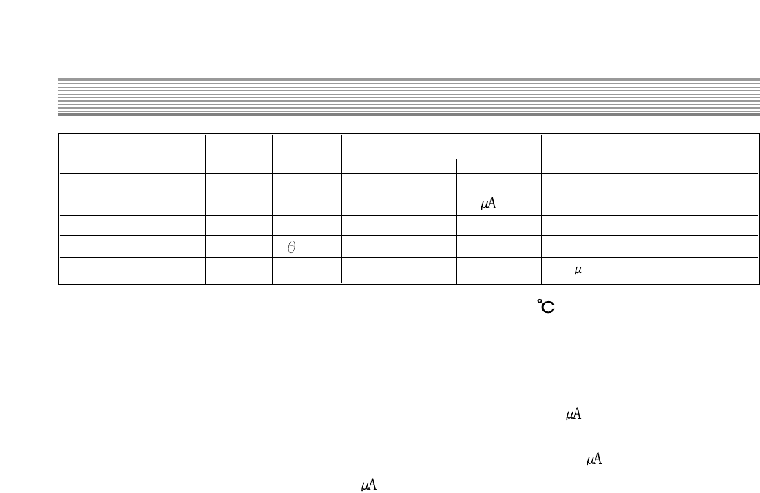
<Electrical features of MOSFET(Ta=25 >
4) Explanation for operation
When the VIN terminal (Pin No.4) voltage of STR-F6656, which is charged in C815 and C822
via starting resistance (R809+R817) and (R823+R824) at the early starting, reaches 10V, a
control circuit in SRT-F6656 starts.
Since the circuit current before 6656 operation is limited to 400 (MAX), a high starting
resistance can be used.
Because a sustaining current of latch circuit in 6656 is set to 500 (MAX), this starting
resistance needs to be set so that 500 or more current flows though AC input power is the
lowest.
Because the time until control circuit in 6656 starts is determined after AC input voltage is
input by (R809+R817), (R823+R824) and C815, C822 product, the power start gets slow if
C815 and C822 is set too high.
The voltage via a coil D (d1) of trans (T802. T803) is rectified and smoothed after operation
of 6656 and a stable voltage is supplied for Vin terminal. For coil D1, approx. 15.5V voltage is
rectified and smoothed via R813, R818, D810, D813, C815 and C822 and approx. 15V
voltage is supplied for Vin terminal of 6656.
Since VIN (OFF) voltage is set to 10V (TYP) in 6656, the terminal voltage supplied for Vin
terminal should not be less than 10V (15V at present). The voltage of coil d1 should be set
over operation stop voltage (VIN(OFF)=10V(MAX)) and under OVP operation voltage
(VOVP=16V(MIN)) at normal operating state.
5) Protection circuit
5-1) OCP circuit
This is an overcurrent protection circuit of pulse by pulse type that the peak of MOSFET
drain current is detected by 1 pulse and the output of oscillator is reversed.
To detect the MOSFET drain current, R810 and R820 are connected between source
terminal (Pin No.2) and GND terminal (Pin No.5) of MOSFET and the voltage drop is input to
OCP/FB terminal. The threshold voltage of OCP/FB is set to approx. 0.78V for GND.
5-2) Latch circuit
This circuit stops the operation of power circuit, keeping the oscillator output low when the
overvoltage protection circuit and overheat protection circuit are operated.
Because the circuit current gets less than 400uA when Vin terminal voltage is lower than
operation stop voltage (10V), it begins to increase. Because the circuit current increases
again when it reaches operation start voltage (16V), it decreases. Therefore, this circuit
prevents the Vin terminal voltage from rising, making it goes up and down between 10V and