en-3
ELECTRICAL CONNECTION
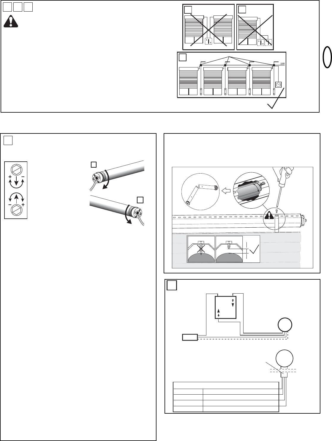
Never connect more than one motor to a timer or wall
switch without using a central module – (h) (available as an
accessory), i.e. one central module is required for each
connected motor.
For a left-side motor installation, follow the wiring diagram exactly as
shown in the control accessory package.
For the correct direction of rotation in a right-side motor installation,
electrical wires (brown & black) must be reversed between the control
accessory and the motor. (See instructions packed with the accessory
you have chosen).
Have the electrical hook-up done by a qualified electrician in
compliance with your local electrical code.
I
SETTING THE LIMITS
“Open” and “Close” Positions
In general the following applies:
+ = Stops later
– = Stops earlier
#1 White screw
#2 Red screw
My roller shutter box is:
A: Aleft-handed installation. I look into the box and the limit switch of
the motor is on the left (see Fig. L1)
White = Limit switch ATBOTTOM
Red = Limit switch ATTOP
B: Aright-handed installation. I look into the box and the limit switch
of the motor is on the right (see Fig. L2)
Red = Limit switch ATBOTTOM
White = Limit switch AT TOP
The bottom adjusting screw is always for the upper limit and the upper
is always for the lower limit, no matter whether the motor is pushed into
the shaft from the right or the left.
PLEASE READ THROUGH AND NOTE THE FOLLOWING
INSTRUCTIONS ACCURATELY BEFORE SETTING THE END
POSITIONS.
Connect a suitable switch to the roller shutters. Run the roller shutter
drive downwards until it switches itself off and then (and only then)
attach the roller shutter jacket to the shaft.
Advice: In order to fix the roller shutter hangers to the shaft, ONLY
use short fixing screws. If the screws are too long damage may occur
to the motor. The recommended fixing method for the hangers is
without screws by means of spring band loops (which are hooked on).
Allow drive to run upwards. If it switches off too early the bottom
adjusting screw must be adjusted in the plus direction. Each full turn of
this screw extends the travel path by about 40° of one turn of the
motor. The motor should stop just a few inches below the window
frame. If not the adjusting screw should be adjusted in the minus
direction. After this the drive must be driven back a little and then up
again to check the result.
It is possible that the drive will switch itself off after several trips
because it has reached a temperature which is too high. Howevere
after 15 – 20 minutes cooling time it will be ready to operate again.
Please note that the limit switches of the drive only function
properly if the drive has been installed correctly and is completely
within the shaft.
L
J K
Advice: In order to fix the roller shutter hangers to the shaft,
ONLY use short fixing screws. If the screws are too long damage
may occur to the motor. The recommended fixing method for the
hangers is without screws by means of spring band loops
(which are hooked on).