Getting Started! – First Steps
As you unpack your telescope, carefully note the following parts. The
assembly is shipped in separate boxes.
Telescope Assembly
• Equatorial mount with polar alignment finder
• Heavy duty, adjustable steel tube tripod with leg braces, three tripod leg
lock knobs, and a captive mount locking knob
• Complete optical tube assembly including primary mirror with dust cover
and a rack-and-pinion focuser and eyepiece holders for both 1.25" and
2" eyepiece holders, tube cradle assembly with two rings and two lock
knobs
• Eyepiece
• Counterweight and counterweight shaft. Some models include an
additional counterweight.
• 8 x 50mm or 6 x 30mm viewfinder
How to Assemble Your Telescope
The giftboxes contain the optical tube assembly and the tripod with the
equatorial mount. The accessories are located within compartments
custom-cut into the styrofoam block inserts.
1. Remove the components from the giftboxes. Remove and identify the
telescope’s equipment. Refer Figures 1a to 1f for images of the parts
and the overall assembly of your telescope. When removing the tripod
from the giftbox, hold the assembly parallel (horizontal) to the ground or
the inner tripod leg extensions will slide out as they are not locked in
place.
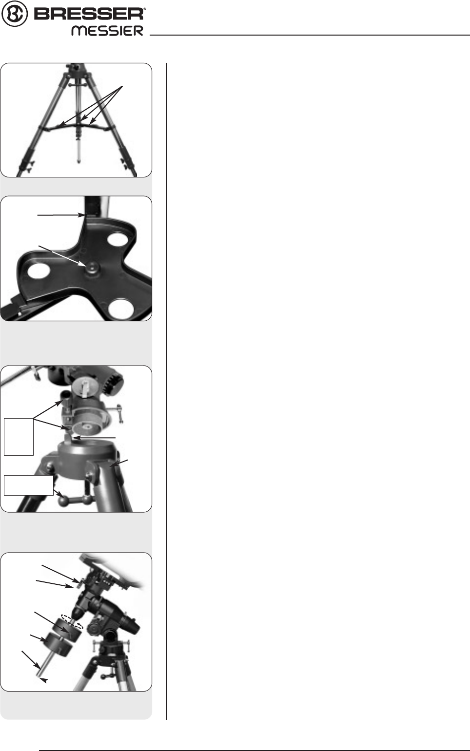
2. Adjust the tripod legs. Spread the tripod legs as far as they will open,
so that the leg braces are taut. See Fig. 3.
3. Attach the accessory shelf to the tripod. Place the triangular accessory
shelf on top of the leg braces so that each corner of the triangle lies
over a leg brace. Notice that there is protrusion on each leg brace.
There is a corresponding slot for each protrusion on the accessory tray.
See Fig. 4. Line up the slots with the protrusions and slide the
protrusions through the slots to hold the tray in place.
4. Attach mount to tripod base. Place the mount over the base of the
tripod with the computer control panel positioned above the tripod leg
marked with a star and with the protrusion on top of the tripod's base
positioned between the fine azimuth control knobs. See Fig. 5. Back off
the azimuth control knobs wide enough for protrusion to fit between
them. Slide the hole in the center of the underside of the mount onto
the captive mount locking bolt in the center of the base and tighten it by
turning the knob below the base. Tighten to a firm feel.
5. Attach the counterweight(s) to the counterweight shaft. Place the counter-
weight shaft base (20, Fig. 1d) over the threaded end of the shaft (22, Fig.
1d). Thread the shaft and base assembly into the hole beneath the Dec.
setting circle as depicted in Fig. 6. Look through the hole in the
counterweight and note the pin blocking the hole. Tilt the counterweight
slightly and the pin moves out of position, clearing the hole. If the pin does
not move, unscrew the counterweight lock knob slightly until the pin moves.
Unscrew the safety cap (23, Fig. 1d) from the shaft. Holding the
counterweight (21, Fig. 1d) firmly in one hand, slip the counterweight to
approximately the midpoint of the counterweight shaft (22, Fig. 1d). Tighten
the counterweight lock knob to a firm feel. Replace the safety cap.
NOTE:
If the counterweight ever slips, the safety cap (23, Fig. 1d) prevents the
counterweight from sliding entirely off the shaft. Always leave the safety
cap in place when the counterweight is on the shaft.
Looking at or near the Sun will cause instant and irreversible damage to your eye!
8
FIRST STEPS
Fig. 3: Tripod assembly
Fig 4: Place slots in tray over prot-
rusions on leg braces
Fig. 5: Attach the mount to the tri-
pod
Locking
protrusion
leg
braces
Abb. 6: ATtach counterweight
assembly (here: MON 2)
Shaft
Safety cap
Lock knob
Counterweight
shaft base
DEC-setting circle
Mounting
thumbscrew
protrusion
fine
Azimuth
control
knobs
star
Mount
locking knob