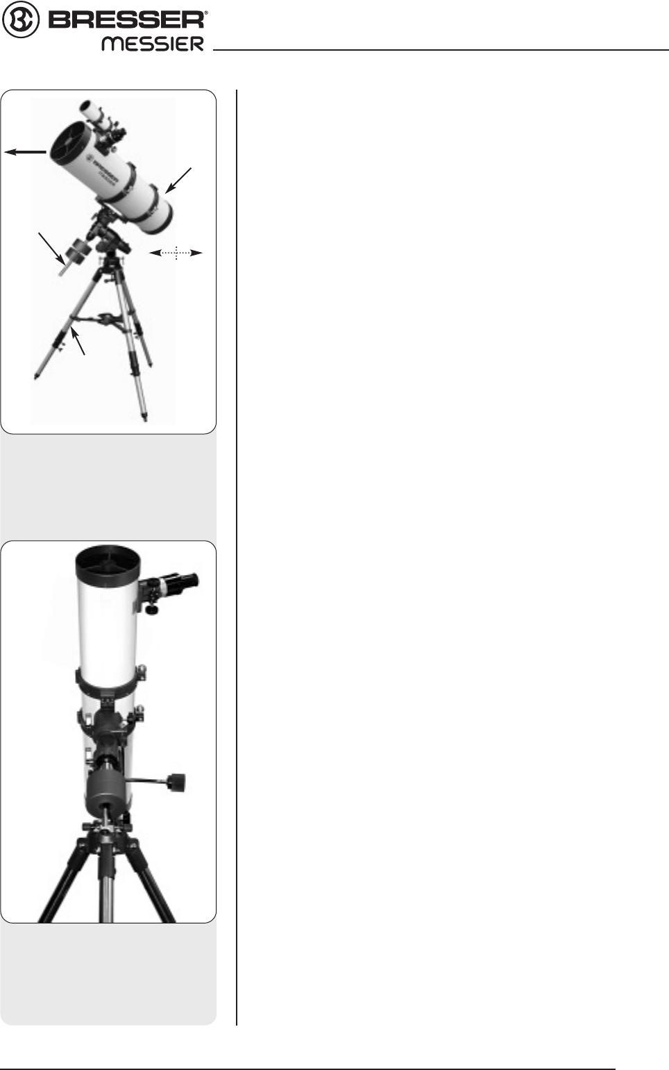
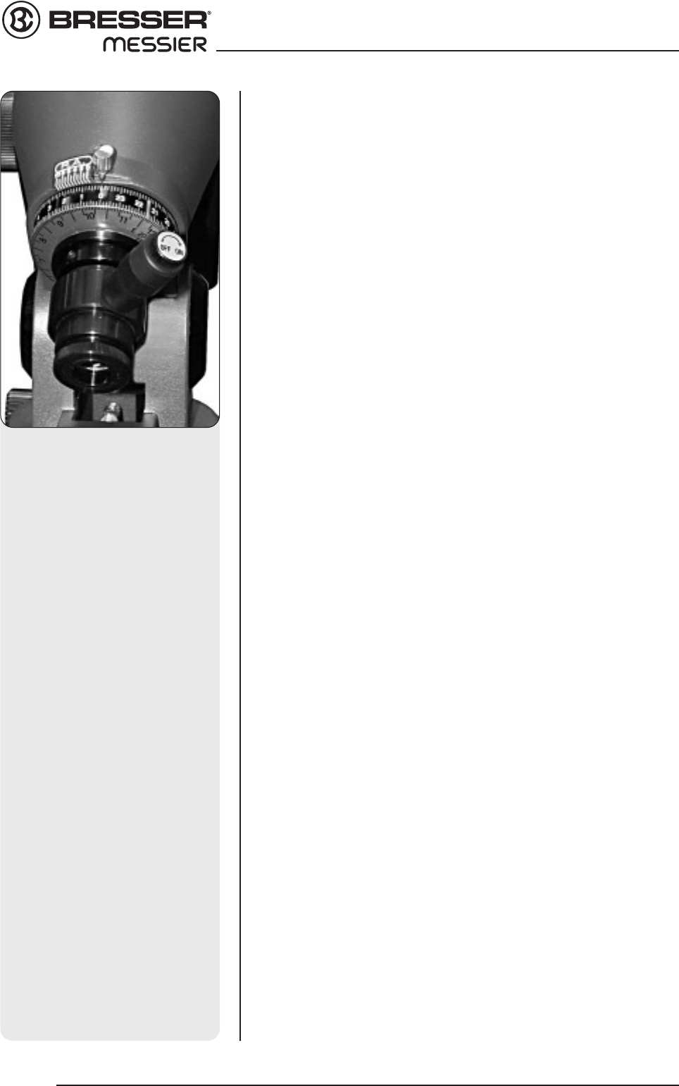
6. Set the latitude. Setting the latitude is easier if it is set before you attach
the optical tube to the assembly. Locate the latitude dial (28, Fig. 1d); note
that there is a triangular pointer above the dial located on the mount. The
pointer is not fixed; it moves as the mount moves.
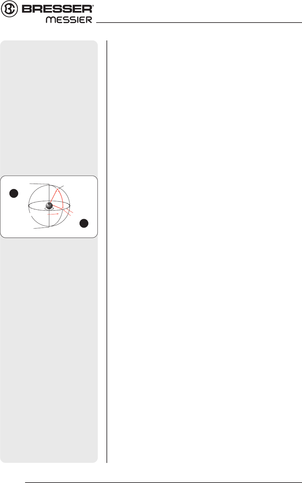
Determine the latitude of your observing location. See APPENDIX B:
LATITUDE CHART, page 25, for a list of latitudes, or check an atlas. Move
the latitude T-handle screws in order to move the mount until the pointer
points to your latitude. The two T-handle screws (MON 2 only) work in a
"push - pull" operation—as you tighten one, loosen the other. When the
pointer points at your latitude, tighten both screws until they make contact
with the mount. The MON 1 has on screw with similar operation.
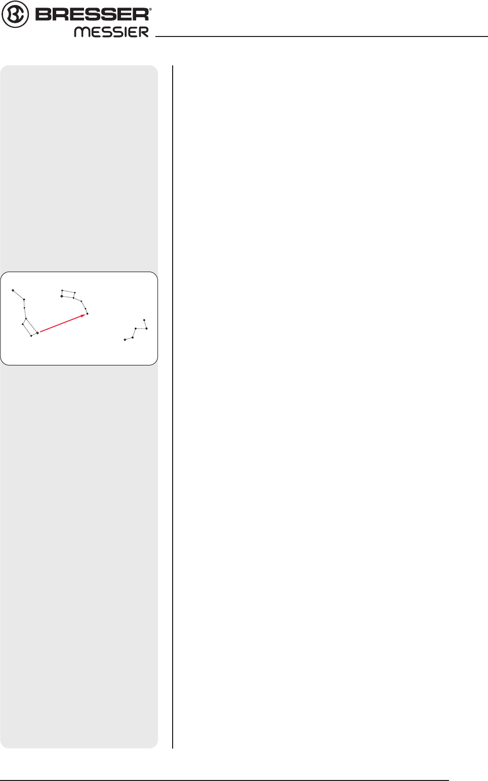
At your observing site, set up the telescope assembly so that this leg
approximately faces North (or South in the Southern Hemisphere).
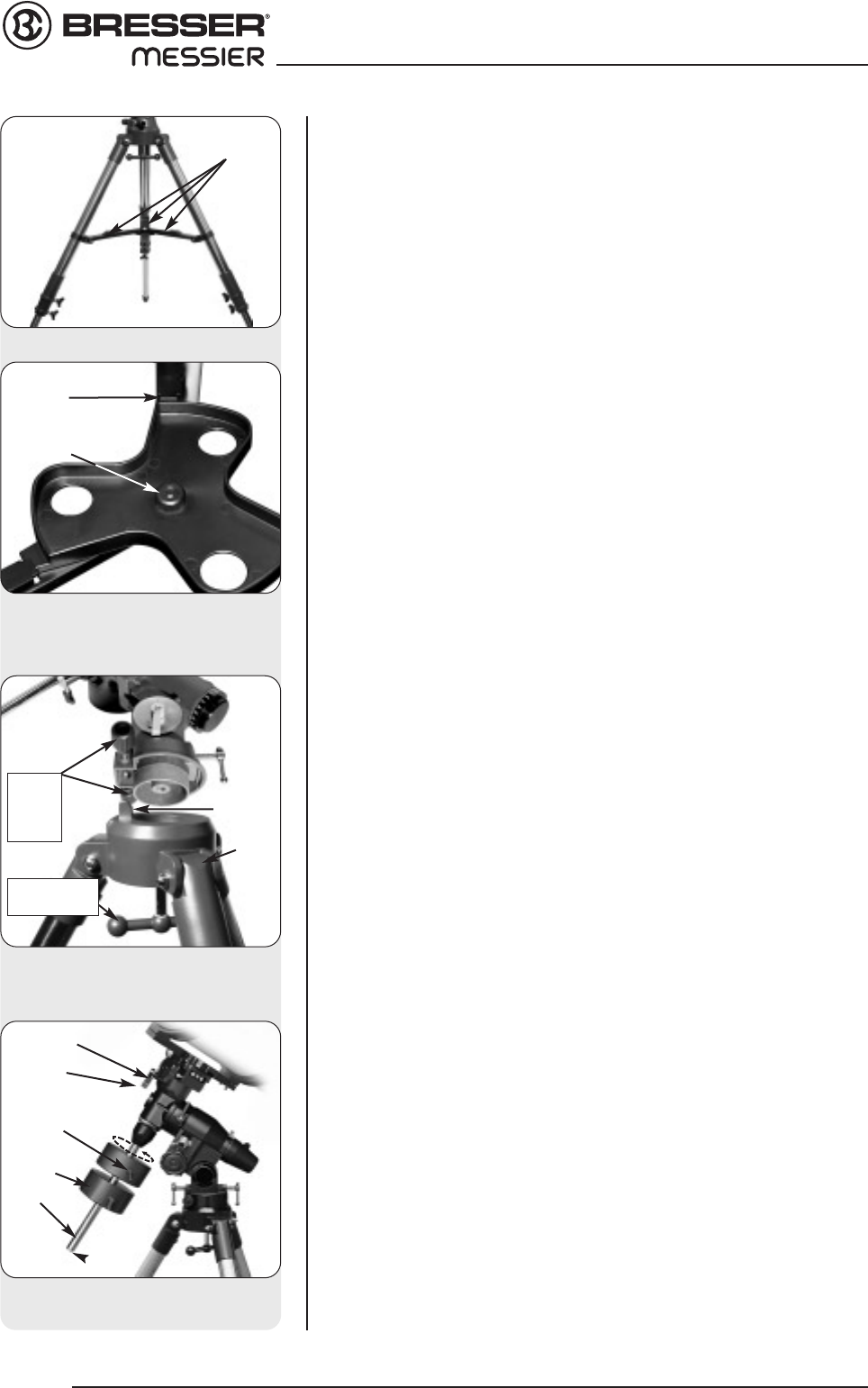
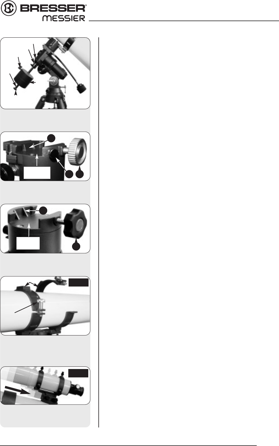
7. Attach the cradle assembly to the mount
–
Models R and N: Remove the
optical tube from the cradle and slide the cradle assembly (11, Fig. 1a)
onto the cradle mounting slot. See Fig. 7. The rounded base of the cradle
assembly fits into the rounded portion of the mounting slot. Tighten both
the cradle locking knob and the secondary locking knob to a firm feel.
8. Position optical tube –
Models R and N:
Unscrew the cradle ring lock
knobs (13, Fig. 1a) and open the cradle rings. While firmly holding the
optical tube (10, Fig. 1a), position it onto the cradle rings (14, Fig. 1a)
with the mid-point of the optical tube’s length lying roughly in the center
of the cradle ring assembly. Point the tube so that the front end (this
end comes shipped with the dust cover (9, Fig. 1a) over it) is oriented as
depicted in Fig. 1a. Then close the cradle rings (14, Fig. 1a) over the
optical tube. Loosely tighten the cradle ring lock knobs just to hold the
tube securely in place until you balance it. See Balancing the
telescope, page 10.
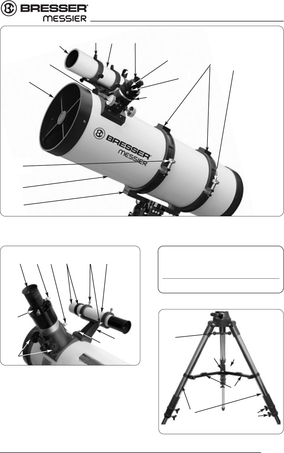
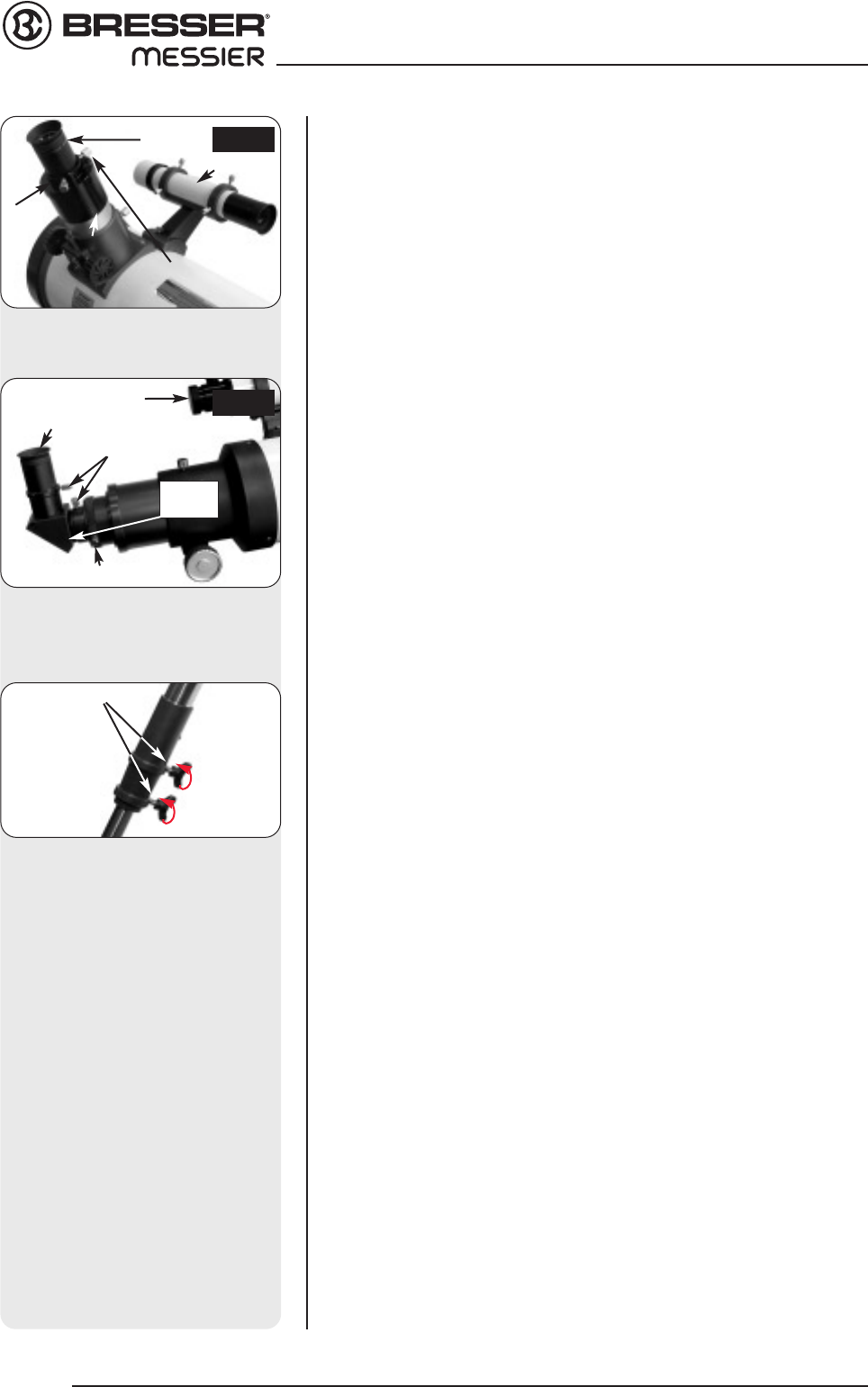
9.
Attach viewfinder bracket
(Abb. 9b). Locate the viewfinder bracket
screws (15, Fig. 1b and Fig. 9a) and remove the nuts from the screws.
Slide the holes in the viewfinder bracket over the viewfinder bracket
screws. Replace the nuts and tighten to a firm feel only.
9a. Attach viewfinder tube:. Back off the viewfinder collimation screws (5,
Fig. 1b) and slide the viewfinder tube into the bracket. Orient the view-
finder eyepiece as depicted in Fig. 1b. Tighten the collimation screws
to a firm feel. See Aligning the viewfinder, page 11.
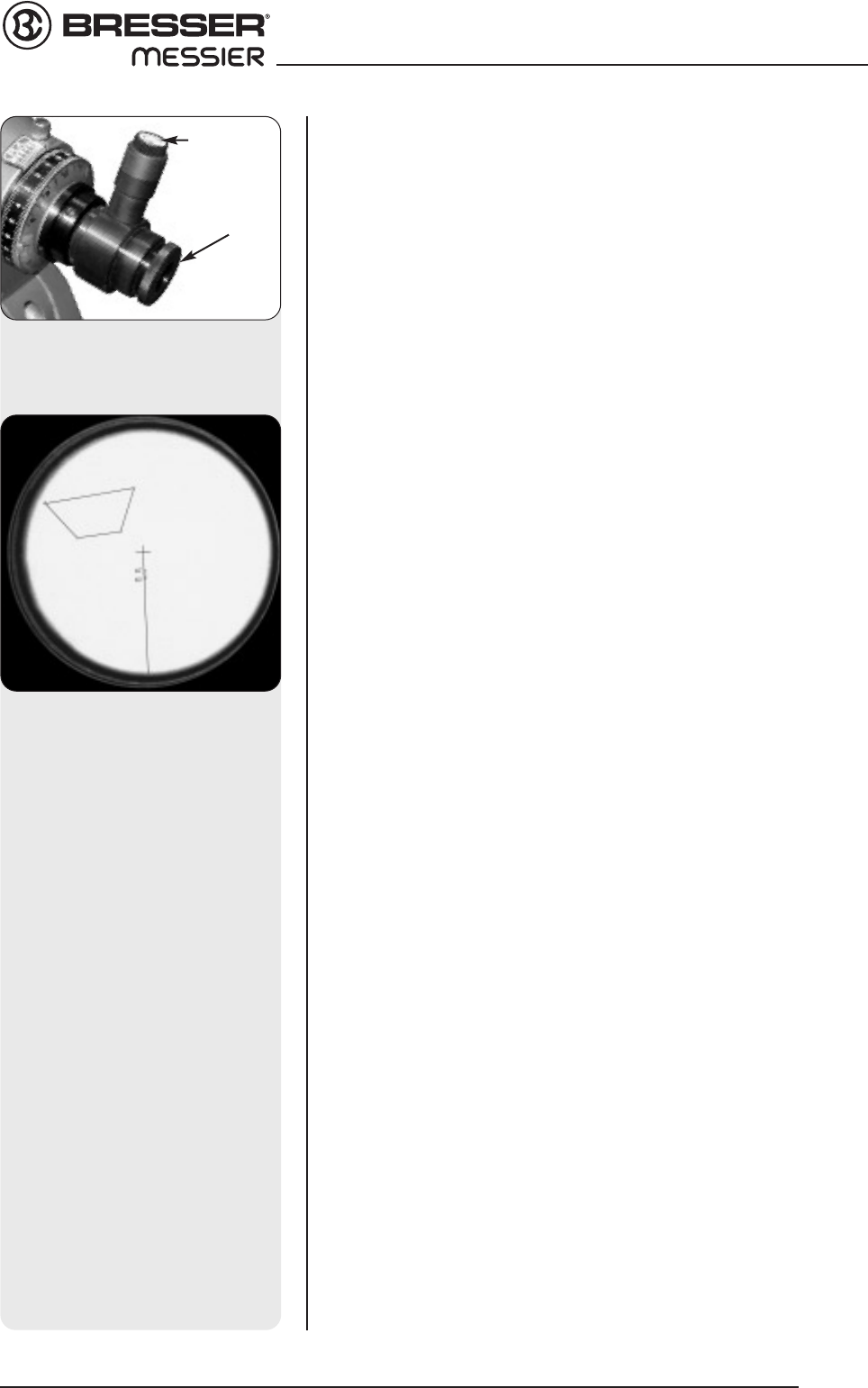
10. Insert the eyepiece: N models (Fig. 10a): Lift to remove the dust cap
from the eyepiece holder on the focuser assembly. Set the dust cap
aside in a safe place and replace it when you have finished observing
to protect the eyepiece assembly. Back off the eyepiece thumbscrews
(1, Fig. 1a) and insert the supplied 25mm eyepiece (3, Fig. 1a) into the
the eyepiece holder. Tighten the holder thumbscrews to a firm feel to
secure the eyepiece..
R models (Abb. 10b): Lift to remove the dust cap from the eyepiece
holder on the focuser assembly. Set the dust cap aside in a safe place
and replace it when you have finished observing to protect the
eyepiece assembly. Back off the eyepiece thumbscrews (1, Fig. 1b) and
slide the diagonal prism into the holder and tighten the thumbscrews to
a firm feel only. Insert the supplied 25mm eyepiece (3, Fig. 1b) into the
the diagonal prism. Tighten the prism's thumbscrews to a firm feel to
secure the eyepiece.
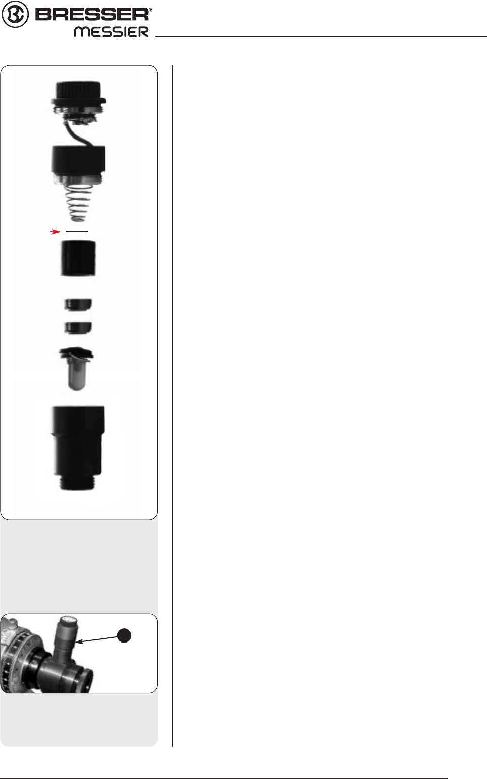
NOTE:
Two eyepiece holders are included with your telescope—for both 1.25" and
2" eyepieces.To change eyepiece holders, unscrew the attached holder
from the focuser and thread on the other holder.
11. Adjust the height of the tripod: Adjust the height of the tripod by
loosening the tripod lock knobs (Fig. 11). Extend the sliding inner
section of each tripod leg to the desired length; then tighten each knob.
Adjust the tripod to a height that is comfortable for viewing.
13. Remove Plastic from Reticle LED: The polar alignment reticle LED
(30, Fig. 1d) contains two watch batteries. The reticle's LED is shipped
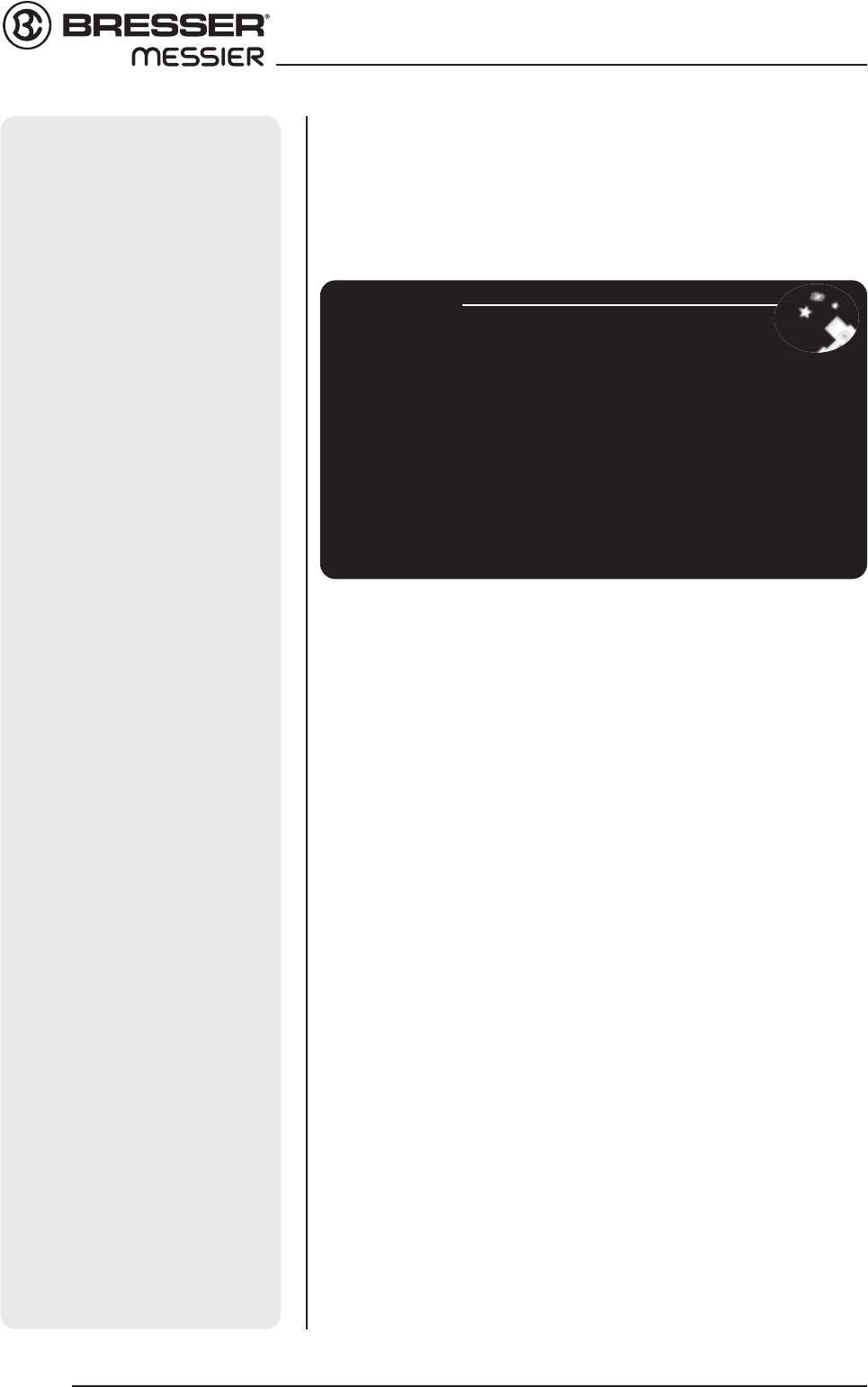
Looking at or near the Sun will cause instant and irreversible damage to your eye!
9
FIRST STEPS
Fig. 9: Viewfinder assembly. Slide
bracket into slot.
Fig. 8: Place the optical tube in
rings and loosely tighten the crad-
le ring lock knobs.
Cradle rings
Lock
knobs
R/N
R/N
Fig. 6a: Attach counterweight
assembly (MON1)
Safety cap
Lock knob
Shaft
Counter
weight
Shaft base
DEC-setting circle
Fig. 7a: Attach cradle to base mounting
and tighten locking (MON1)
Cradle
assembly
A
B
Fig. 7: Attach cradle to base mounting
slot and tighten locking (MON2)
Cradle
assembly set
A
BC