714528
16
Zoom out
Zoom in
Previous page
1/48
Next page
ENEN
BFIASUMEN-005
www.bora.com
Operating and installation instructions BFIAS (BFIA, BFIU)
BORA Basic induction-glass-ceramic-cooktop with cooktop
extractor – exhaust/recirculation
Operating and installation instructions: Original Translation
Manufacturer
BORA Vertriebs GmbH & Co KG
Innstraße 1
6342 Niederndorf
Austria
Contact
T +43 (0) 5373 / 62250-0
mail@bora.com
www.bora.com
The distribution and duplication of this document, as well as the use and disclosure of its contents are prohibited
unless expressly authorised.
These operating and installation instructions have been drawn up with the greatest of care. But it cannot be ruled
out that subsequent technical modifications have not yet been incorporated or the relevant content has not yet been
adapted. Please accept our apologies in this eventuality. An updated version can be requested from the BORA Service
Team. Subject to printing errors and mistakes.
© BORA Vertriebs GmbH & Co KG
All rights reserved.
EN
3
www.bora.com
Table of Contents
1 General information 4
1.1 Target group ................................................................ 4
1.2 Validity of the operating and installation
instructions .................................................................4
1.3 Other applicable documents ......................................4
1.4 Presentation of information ........................................5
2 Safety 6
2.1 General safety instructions ......................................... 6
2.2 Safety instructions – Cooktop operation ...................7
2.3 Safety instructions – Cooktop extractor ....................9
2.4 Safety Instructions – Installation ................................9
2.5 Safety instructions – Cleaning and Maintenance ....11
2.6 Safety instructions – disassembly and disposal ......11
2.7 Safety instructions – spare parts .............................11
2.8 Use as intended ........................................................11
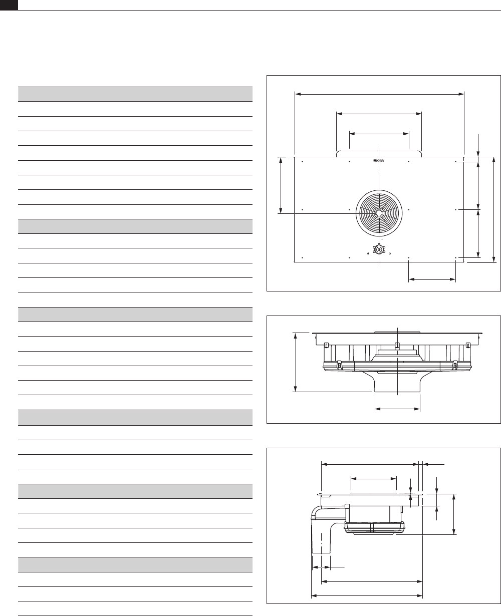
3 Technical data 12
4 Energy label 14
5 Device description 15
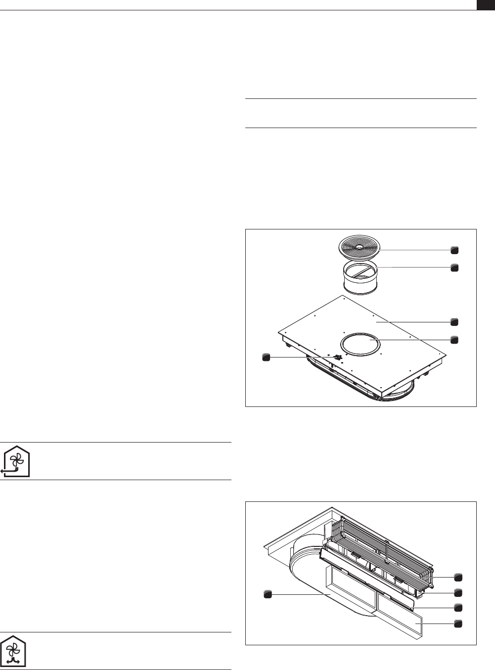
5.1 Structure ...................................................................15
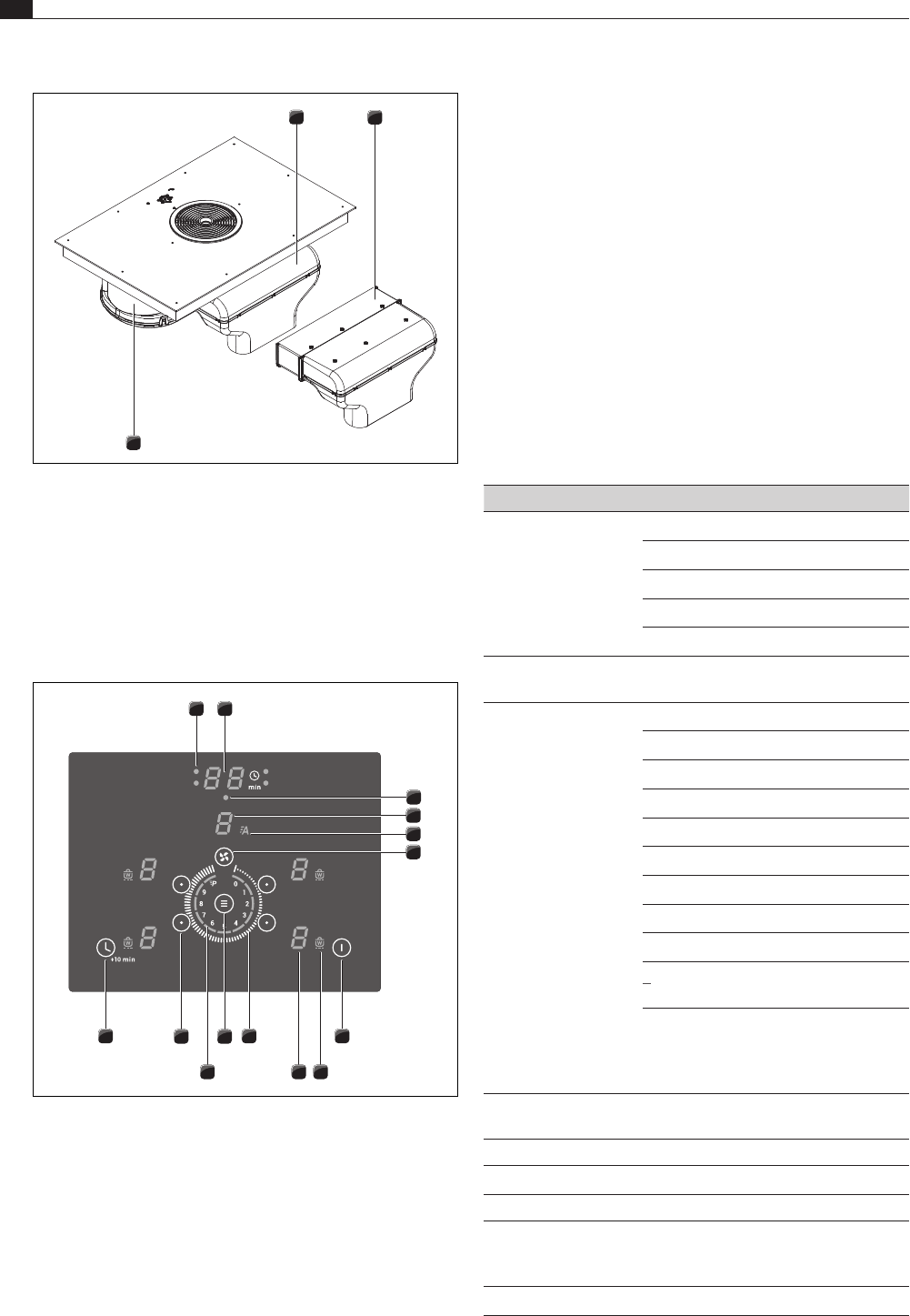
5.2 Operating panel and operating principle ..................16
5.3 Functional principle of the cooking zone .................17
5.3.1 Power levels ..............................................................17
5.3.2 Automatic heat up function ......................................17
5.3.3 power setting ............................................................17
5.3.4 Heat retention levels .................................................17
5.3.5 Bridging function .......................................................18
5.3.6 Pause function ..........................................................18
5.3.7 Timer functions .........................................................18
5.3.8 Pan size recognition ..................................................18
5.3.9 Suitable cookware ....................................................18
5.4 Functional principle of the cooktop extractor ..........18
5.4.1 Freely adjustable power control ...............................18
5.4.2 Automatic cooktop extractor function .....................18
5.4.3 Power setting ............................................................19
5.4.4 Automatic after-run ...................................................19
5.4.5 Filter service display .................................................19
5.4.6 Interface communication ..........................................19
5.5 Safety devices ...........................................................19
5.5.1 Residual heat display ................................................19
5.5.2 Safety shut-down ......................................................19
5.5.3 Overheating protection .............................................19
5.5.4 Automatic switch-off if the button is pressed and
held ............................................................................19
5.5.5 Childproofing feature ................................................19
6 Installation 20
6.1 Checking the scope of delivery ................................20
6.2 Tool and aids .............................................................20
6.3 Assembly instructions ...............................................20
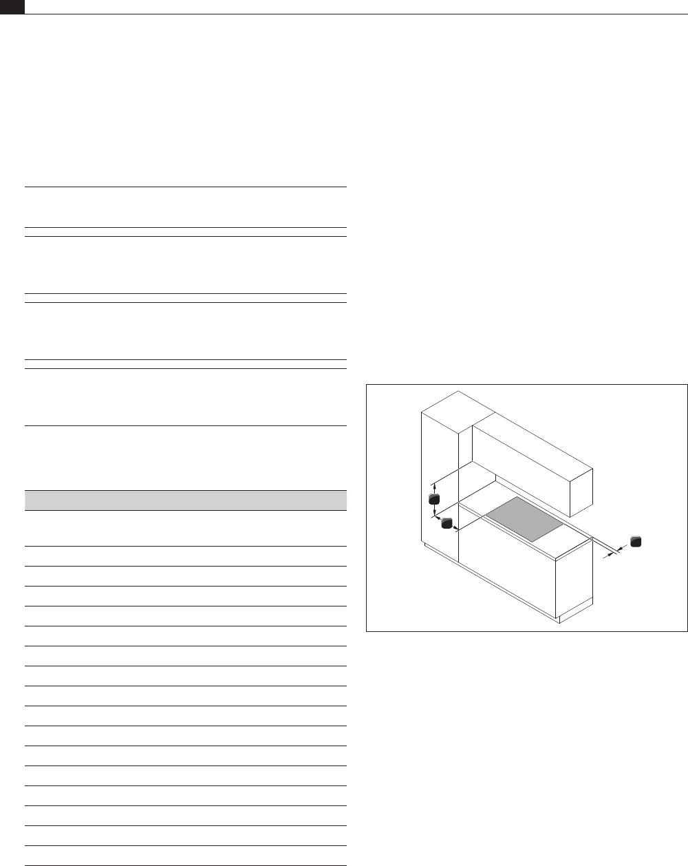
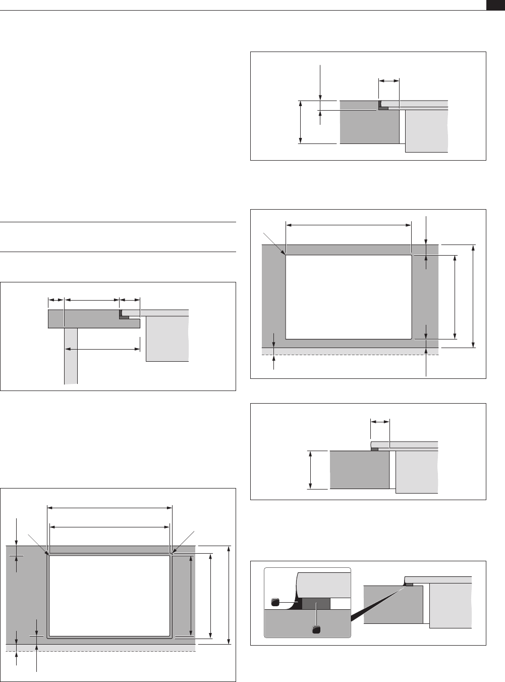
6.3.1 Safety distances ........................................................20
6.3.2 Worktop and kitchen units .......................................20
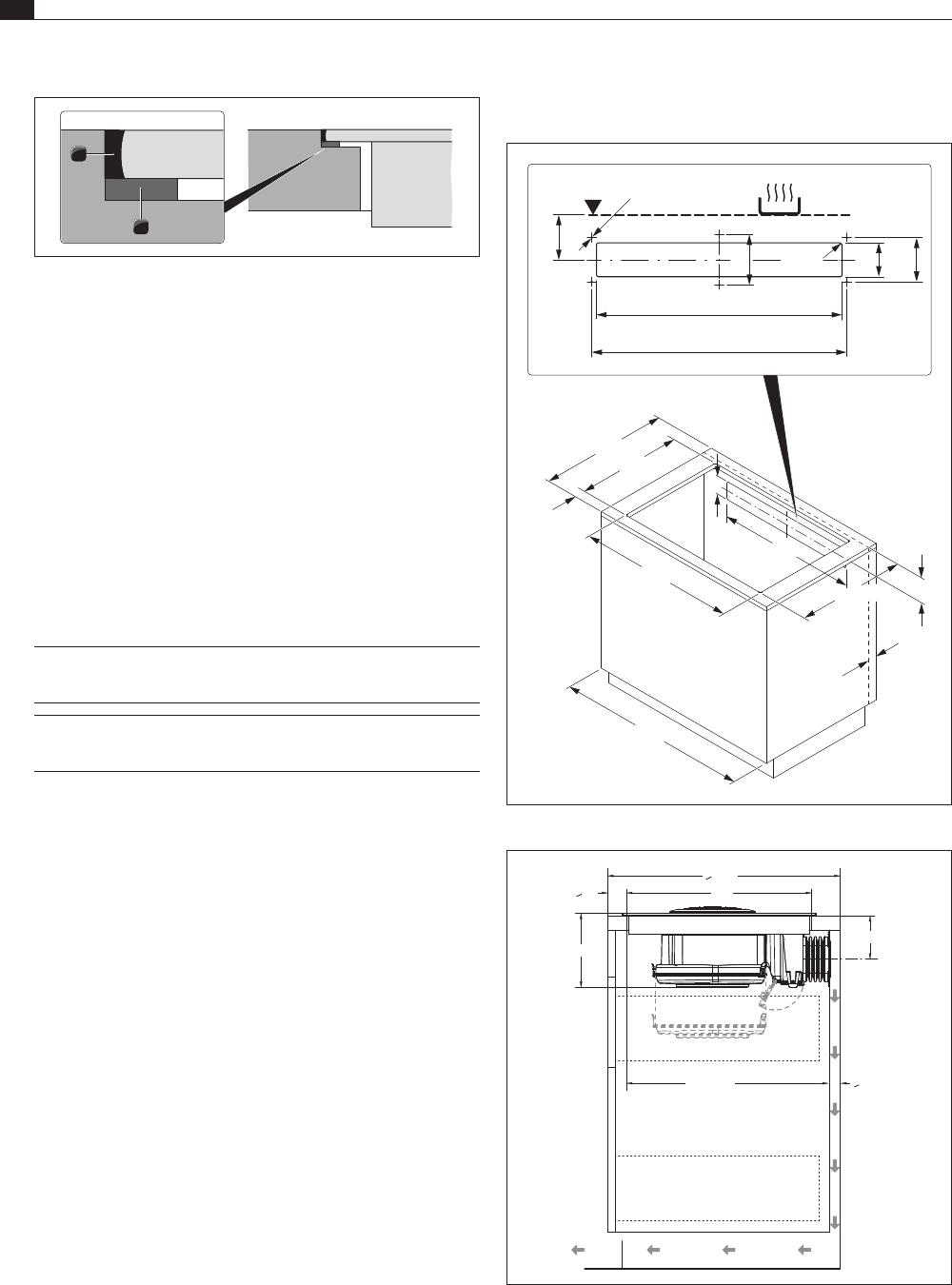
6.4 Cut-out dimensions for the cooktop ........................21
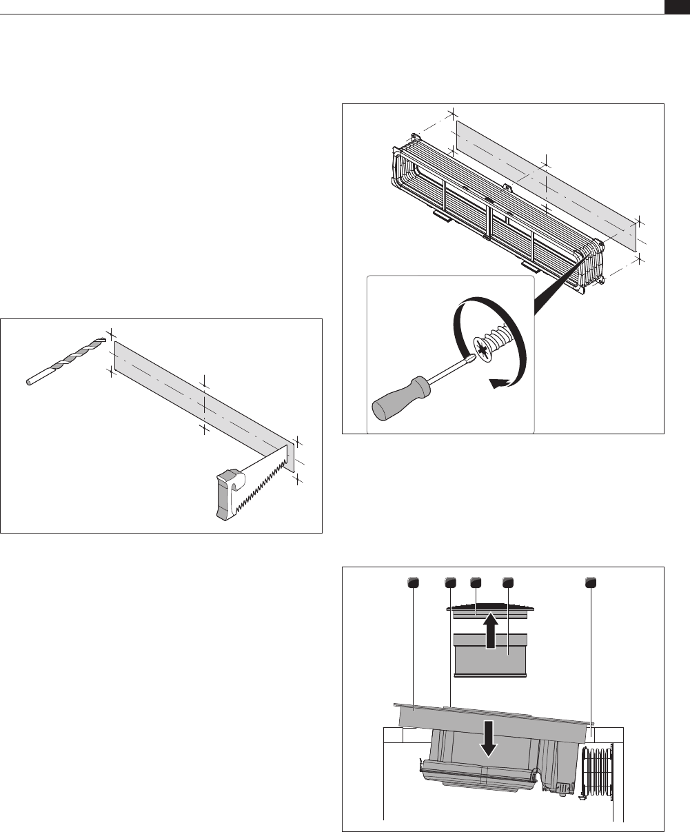
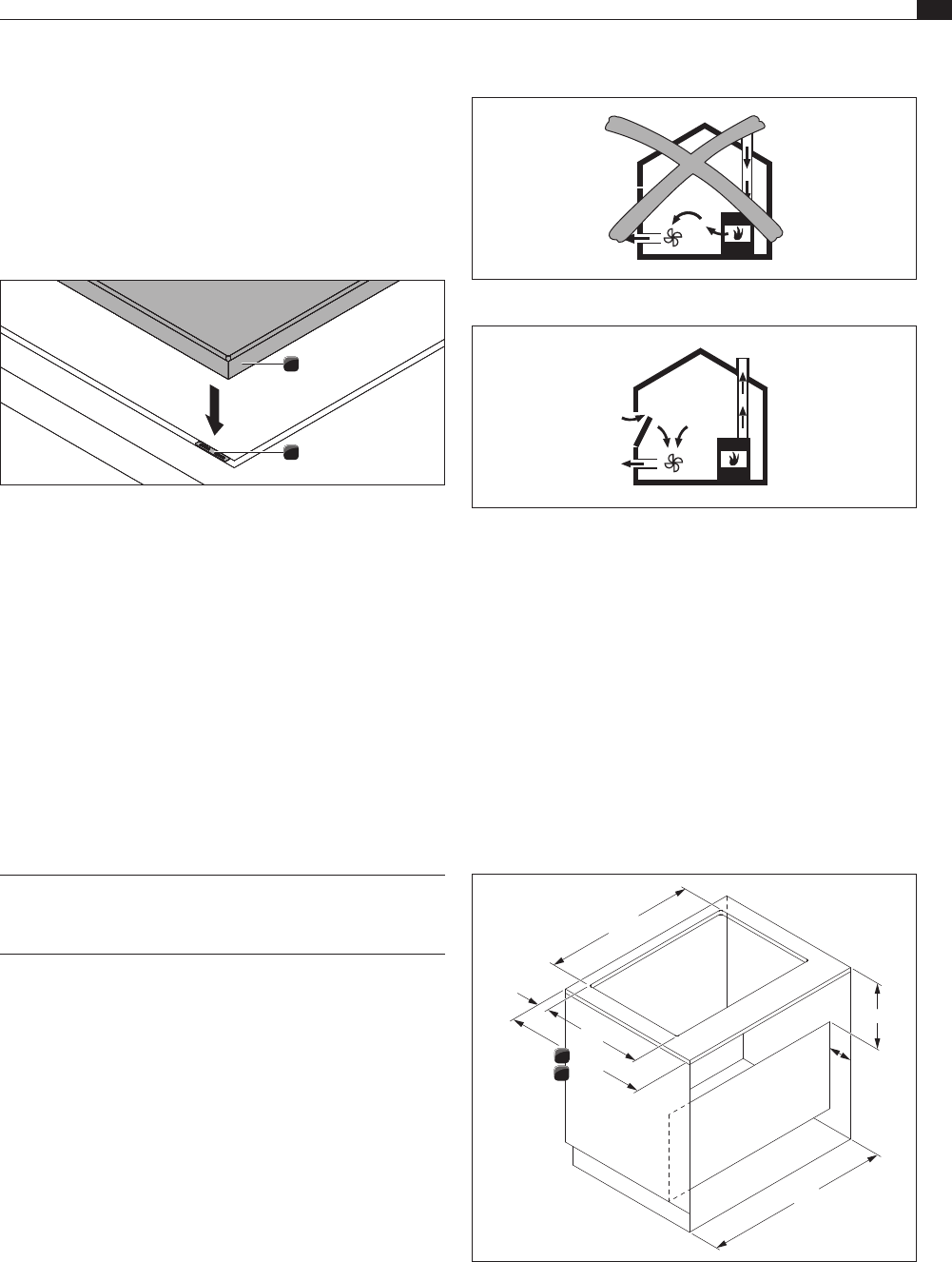
6.5 Attaching the sealing tape ........................................21
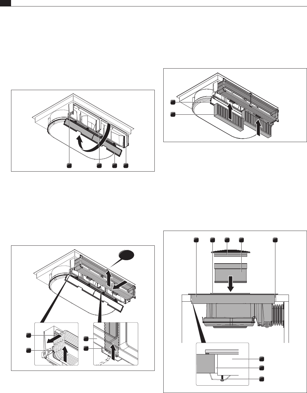
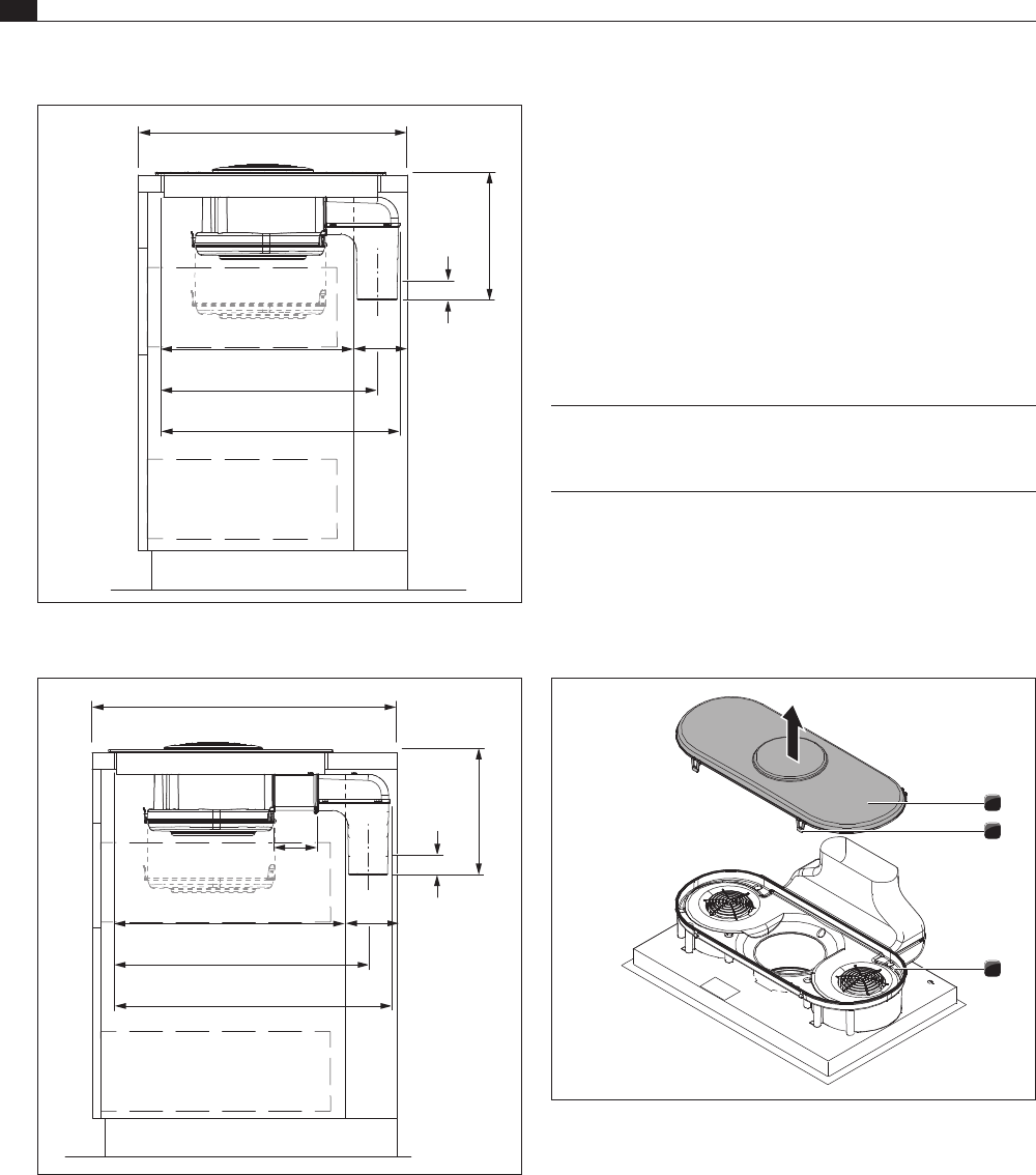
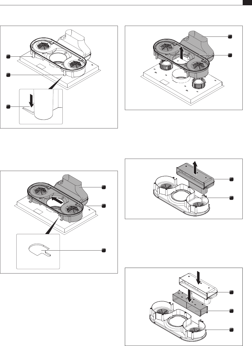
6.6 Installing the recirculation version (BFIU) ................22
6.7 Installing the exhaust air version (BFIA) ...................25
6.7.1 Operating the cooktop extractor with a fireplace
that depends on the air in the room ........................25
6.8 Establishing the power connection ..........................29
6.9 Device power management
(overall power reduction) ..........................................30
6.10 Connect the external switch contact .......................31
6.11 Handover to user ......................................................32
7 Operation 33
7.1 General operating instructions .................................33
7.2 Operating the cooktop ..............................................33
7.2.1 Select cooking zone ..................................................33
7.2.2 Adjusting the power level .........................................33
7.2.3 Changing the power level .........................................33
7.2.4 Selecting the power setting ......................................33
7.2.5 Switching the power setting off early .......................33
7.2.6 Switching off the cooking zone ................................33
7.2.7 Pay attention to the residual heat display ................33
7.2.8 Pause function ..........................................................34
7.2.9 Bridging function .......................................................34
7.2.10 Switching on the bridging function ...........................34
7.2.11 Switching off the bridging function ..........................34
7.2.12 Automatic heat up function .....................................34
7.2.13 Switching off the automatic heat up function ..........35
7.2.14 Heat retention level ..................................................35
7.2.15 Using the timer function ...........................................35
7.2.16 Switching the signal beep off early ..........................35
7.2.17 Setting the short-time timer (egg timer) ..................35
7.2.18 Switching off the short-time timer
(egg timer) early ........................................................35
7.2.19 Setting the automatic cut-off ....................................35
7.2.20 Switching off the automatic cut-off early .................35
7.2.21 Changing the timer settings .....................................35
7.2.22 Switching the childproofing feature on/off ..............36
7.3 Operating the cooktop extractor ..............................36
7.3.1 Selecting a cooktop extractor ..................................36
7.3.2 Adjusting the power level .........................................36
7.3.3 Changing the power level .........................................36
7.3.4 Selecting the power setting ......................................36
7.3.5 Automatic cooktop extractor function .....................36
7.3.6 Switching off the automatic cooktop extractor
function .....................................................................37
7.3.7 Automatic after-run ...................................................37
7.3.8 Switching off the automatic after-run early .............37
7.3.9 Switching off the cooktop extractor .........................37
7.4 Pay attention to the filter service display .................37
7.5 Saving energy ............................................................37
8 Cleaning and maintenance 38
8.1 Cleaning agents ........................................................38
8.2 Maintaining the cooktop ...........................................38
8.3 Cleaning the cooktop ................................................38
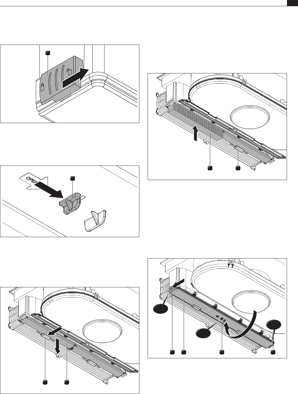
8.4 Cleaning the cooktop extractor ................................39
8.4.1 Removing the air inlet nozzle and stainless steel
grease filter ...............................................................39
8.4.2 Cleaning the air inlet nozzle and stainless steel
grease filter ...............................................................39
8.4.3 Installing stainless steel grease filter and air inlet
nozzle ........................................................................39
8.5 Cleaning the air guiding housing ..............................39
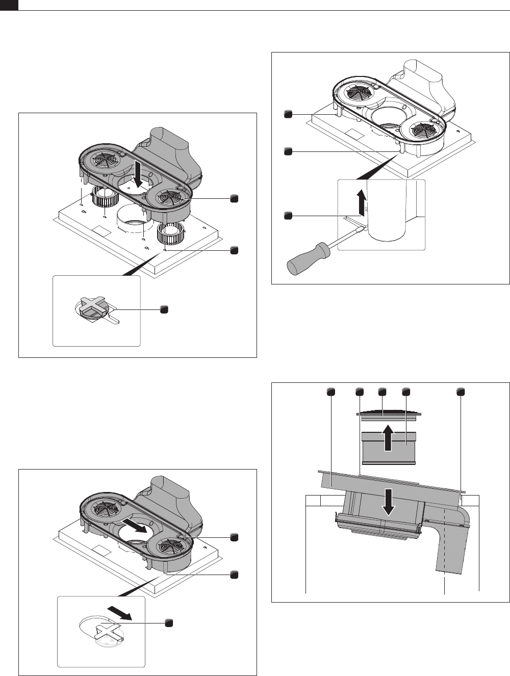
8.5.1 Opening the air guiding housing ...............................39
8.5.2 Closing the air guiding housing ................................40
8.6 Replacing the activated charcoal filter .....................40
9 Troubleshooting 42
10 Decommissioning, disassembly and
disposal 43
10.1 Decommissioning......................................................43
10.2 Disassembly ..............................................................43
10.3 Environmentally-friendly disposal .............................43
11 Warranty, technical service,
spare parts, accessories 44
11.1 BORA manufacturer’s warranty ................................44
11.1.1 Warranty extension ...................................................44
11.2 Service .......................................................................44
11.3 Spare parts ................................................................44
11.4 Accessories ...............................................................45
EN
4
General information
www.bora.com
1 General information
1.1 Target group
These operating and installation instructions apply for the
following target groups:
Target group Requirements
User The appliance can be used by children
aged 8 and above as well as people with
reduced physical, sensory or mental
capacities or a lack of experience and/or
knowledge if they are supervised or have
been instructed how to safely use the
appliance and understand the resultant
risks. Children must be supervised. All
safety and warning information and the
handling instructions in the installation
instructions must be complied with.
Ambitious DIYers Ambitious DIYers can independently
conduct all joinery and installation work
providing they possess the necessary
skills and expertise. They must never
independently establish electricity and
gas connections.
Installation specialists Installation specialists are authorised
to conduct all joinery and installation
work in line with
existing regulations. The
electricity and gas connections must be
certified by a certified engineer for the
applicable trade prior to commissioning.
Electricians The electrical connection may only be
established by a certified engineer.
He/she also assumes responsibility for
the proper electrical installation and
commissioning.
Gas specialists The gas connection may only be
established by certified engineers.
They also assume responsibility for
proper installation and commissioning of
the gas system.
Tab. 1.1 Target groups
INFO BORA Holding GmbH, BORA Vertriebs GmbH
& Co KG, BORA APAC Pty Ltd and BORA
Lüftungstechnik GmbH - hereinafter referred to
as BORA - do not assume any liability for damage
arising from non-adherence to these documents
and from improper assembly! The electricity and
gas connections must be made by a qualified
specialist. Installation must comply with the
valid standards, regulations and laws. All safety
and warning information and the operating and
installation instructions must be complied with.
1.2 Validity of the operating and
installation instructions
These instructions apply to several device versions. It is
therefore possible that some of the features described do
not apply to your appliance.
1.3 Other applicable documents
These operating and installation instructions are valid
in conjunction with other documents, which must be
adhered to.
Please be sure to adhere to all documents that form part
of the scope of delivery.
INFO BORA accepts no liability for damage caused by
failure to comply with these documents!
Directives
This device meets the following EU/EC directives:
2014/30/EU EMC Directive
2014/35/EU Low Voltage Directive
2009/125/EC Ecodesign Directive
2010/30/EU Energy Consumption Label Directive
2011/65/EU RoHS Directive
2012/19/EU WEEE Directive
EN
5
General information
www.bora.com
1.4 Presentation of information
To make working with these instructions quick and
easy, consistent formatting, numbering, symbols,
safety instructions, terms and abbreviations are used
throughout.
Handling instructions are market with an arrow.
Always carry out handling instructions in the sequence
shown.
Bullet points are indicated by a square bullet point at
the edge of the line.
Bullet point 1
Bullet point 2
INFO Information points out specific points you must
always comply with.
Safety and warning information
The safety and warning information in these instructions
are highlighted with symbols and signal words.
Safety and warning information is structured as follows:
WARNING SYMBOL AND SIGNAL
WORD!
Type and source of the danger
Consequences of non-compliance
Measures to minimise risk
The following applies:
The warning symbol draws attention to the danger.
The signal word indicates the severity of the risk.
Warning sign Signal word Hazard
Danger Indicates an imminent hazardous
situation which could lead to
death or serious injury
if ignored.
Warning Indicates an imminent hazardous
situation which could lead to
death or serious injury if
ignored.
Caution Indicates a potentially hazardous
situation which could lead to slight
or minor injuries if ignored.
Caution Indicates a situation which could
result in material damage if
ignored.
Tab. 1.2 Meaning of warning symbols and signal words
EN
6
Safety
www.bora.com
2 Safety
2.1 General safety instructions
INFO The appliance complies with the
stipulated safety requirements. The
user is responsible for appliance
cleaning and maintenance as well as
its safe use. Improper use can lead
to personal injury and damage to
property.
The operating and installation instructions
contain important information about
installation and operation. These enable you
to protect yourself against injuries and
prevent damage to the appliance. Contact
details for further information as well as
application and usage questions can be found
on the back of these operating and
installation instructions.
The term “appliance” is used to refer to
cooktops, cooktop extractors or cooktops
with integrated cooktop extractor.
Read the operating and installation
instructions fully before using the appliance
for the first time.
Always store the operating and installation
instructions within easy reach so that they
can be accessed if required.
Pass the operating and installation
instructions to the next owner if you sell the
appliance.
Conduct all work extremely attentively and
conscientiously.
Check the appliance for visible damage when
unpacking it.
Do not connect a damaged appliance.
Do not connect the appliance to the mains
until the duct system has been installed or
the recirculation filter has been fitted.
Do not use the appliance until installation is
complete. This is the only way to ensure safe
operation.
Make sure contact with hot cooking surfaces
is not possible.
Do not place any objects on the operating
panel or the cooktop extractor air inlet nozzle.
Switch off the appliance after use.
Keep pets away from the appliance.
CAUTION!
Appliance components can cause
injury if dropped!
Appliance components such as pan
supports, operating controls, covers,
grease lters, etc. can cause injury if
dropped.
Place any appliance components
that have been removed in a safe
place near the appliances.
Ensure that no components removed
from the appliance can fall on the
floor.
Unauthorised modifications
Unauthorised modifications can cause the
appliance to pose risks.
Do not make any changes to the appliance.
Households with children and people with
special needs
The appliance can be used by children aged 8
and above as well as people with reduced
physical, sensory or mental capacities or a
lack of experience and/or knowledge if they
are supervised or have been instructed how
to use the appliance safely and understand
the resultant risks.
Supervise children in the vicinity of the
appliance.
Children must not play with the appliance.
Use the childproofing feature in order to
prevent children from switching on the
cooktop or changing the settings when they
are unattended.
Do not store any items that could be of
interest to children in storage spaces above
or behind the appliance. Otherwise, they will
be tempted to climb onto the appliance.
Keep children and other persons away from
the cooking surfaces when hot.
Recirculation mode
INFO When cooking, additional moisture is
released into the ambient air.
INFO In recirculation mode, only a slight
amount of moisture is removed from
the cooking vapour.
EN
7
Safety
www.bora.com
DANGER!
Risk of electric shock!
Cracks, ssures or fractures in the
glass ceramic panel can damage the
underlying electronics. This can cause
an electrical shock.
If there are any cracks, fissures or
fractures in the glass ceramic,
switch the appliance off
immediately.
Securely disconnect the appliance
from the mains using the LS switch,
fuses, automatic circuit breakers or
contactor.
WARNING!
Risk of burns from hot cooktop!
The cooktop and its exposed areas get
hot during use. Once the cooking zone
is switched o, it takes a little while to
cool down to below 60 °C. Touching
hot surfaces can cause serious burns.
Never touch the cooktop when it is
hot.
Keep children away from the
cooktop when it is hot or ensure
they are supervised at all times.
WARNING!
During or after a power cut, cooktops
may still be hot!
In the event of a power cut, a cooktop
that was previously in operation may
still be hot even though there is no
indication of residual heat.
Do not took the cooktop while it is
still hot.
Keep children away from the hot
cooktop.
WARNING!
Risk of fire from objects on the
cooking surfaces!
The cooktop and its exposed parts are
hot when the cooking zone is switched
on and during the cooling phase.
Objects on the cooktop can heat up
and catch re.
Do not place any items on the
cooktop.
When using recirculation mode, ensure a
sufficient supply of fresh air, e.g. by opening a
window.
Ensure a normal and comfortable room
climate (humidity of 45–60%), e.g. by opening
natural ventilation openings or using domestic
ventilation systems.
After every use in recirculation mode, switch
the cooktop extractor to a low level for about
20 minutes or activate the automatic after-run
function.
2.2 Safety instructions – Cooktop
operation
Avoid over-cooking.
Pay attention to the residual heat display.
Do not place any hot cookware in the area of
the cooktop display so as not to damage the
underlying electronics.
Make sure that the base of the cookware as
well as the cooking zones are clean and dry.
Always lift (do not drag!) the cookware to
prevent scratching and abrasion on the
surface.
DANGER!
Danger of fire caused by leaving the
cooktop unattended!
Oil or fat in the pot can quickly heat up
and ignite.
Never leave oil or fat to heat up
unattended.
Never extinguish oil and fat fires
with water.
Suffocate the fire, for example by
using a lid.
DANGER!
Risk of explosion caused by
flammable liquids!
Flammable liquids in the vicinity of the
cooktop can explode and cause serious
injury.
Do not spray aerosols in the vicinity
of this appliance while it is in
operation.
Do not place any flammable liquids
in the vicinity of the cooktop.
EN
8
Safety
www.bora.com
CAUTION!
Damage from sugary and salty foods!
Sugary and salty foods and juices can
damage the hot cooking zone.
Make sure sugary and salty foods or
juices do not get onto the cooking
zone while it is hot.
Remove sugary and salty foods and
juices from the hot cooking zone
immediately.
CAUTION!
Escaping hot liquids!
Unattended pans can boil over allowing
hot liquids to escape.
Always keep an eye on pans while
cooking.
Short cooking sessions must be
constantly monitored.
CAUTION!
Damage caused by objects on the
cooktop!
Objects such as cookware lids on the
cooktop can damage the glass ceramic
panel.
Do not place any objects on the
cooktop while it is hot.
2.2.1 Safety instructions – cooktop
installation
Do not rely on the pan size recognition.
Effect on pace makers, hearing aids and metal
implants
INFO Induction cooktops generate a high-
frequency electromagnetic field in the
area of the cooking zones. The cooking
zones may affect pacemakers, hearing
aids or metal implants negatively or
disturb their function when in close
proximity. A reduced function of the
pacemaker is unlikely.
If in doubt, contact the manufacturer of your
medical device or your doctor.
WARNING!
Risk of burns from hot objects!
The cooktop and its exposed parts
are hot when the cooktop is in use
and during the cooling phase. Objects
on the cooktop heat up very quickly
and can cause serious burns. This
particularly applies to metal objects
(e.g. knives, forks, spoons, lids or
cooktop extractor covers).
Do not place any items on the
cooktop.
Please use suitable tools (pot
holders, oven gloves).
WARNING!
Risk of burns from hot cookware!
Handles projecting over the edge are
enticing for children to grab.
Do not turn pot and pan handles so
they stick out beyond the work
surface.
Make sure that children cannot pull
hot pots and pans over.
Use suitable stove guards.
Do not use unsuitable stove guards
(accident risk).
To choose a suitable stove guard,
contact your specialist supplier or
the BORA Service Team.
WARNING!
Risk of burns!
Liquid between the cooking zone and
the pan base can evaporate and cause
burns.
Make sure that the cooking zone
and the pan base are always dry.
CAUTION!
Damage from hard and pointed
objects!
Hard and pointed objects can damage
the glass ceramic panel of the cooktop.
Do not use the surface of the
cooktop as a worktop.
Do not use hard and pointed objects
when working on the cooktop.
EN
9
Safety
www.bora.com
2.3 Safety instructions – Cooktop
extractor
Do not place any hot cookware on the air inlet
nozzle of the cooktop extractor.
Make sure that hot cookware does not touch
the edge of the air inlet nozzle.
DANGER!
Risk of smoke inhalation!
Using a replace that depends on the
air in the room produces combustion
gases.
If the cooktop extractor is used in
conjunction with a replace that
depends on the air in the room, toxic
combustion gases (carbon monoxide)
can be extracted from the chimney or
outlet duct into the living area.
Make sure that there is always a
sufficient air supply.
DANGER!
Fire risk from flambéing!
While the cooktop extractor is working,
it sucks up grease from cooking.
Flambéing food can cause the grease
to catch re.
Clean the cooktop extractor
regularly.
Never work with a naked flame while
the cooktop extractor is running.
DANGER!
Fire risk from fat deposits!
If the stainless steel grease lter is
not cleaned regularly, this can lead to
increased levels of grease in it. This
increases the re risk.
Clean and replace the filter at
regular intervals.
CAUTION!
Exposed parts may become hot!
The cooktop extractor and its exposed
parts are hot when the cooking zone
is switched on and during the cooling
phase.
Please use suitable tools (pot
holders, oven gloves).
WARNING!
Risk of injury when opening the
bottom housing cover!
There is a risk of injury while the fan is
turning.
Switch off the cooktop extractor and
the cooktop.
Turn off the mains supply.
CAUTION!
Damage caused by objects or paper
suctioned in!
Small and light items, such as cleaning
cloths made from material or paper,
can be suctioned into the cooktop
extractor. This can damage the fan or
impair the exhaust performance.
Do not store any items or paper on
the cooktop extractor.
CAUTION!
Damage caused by grease and dirt
deposits!
Grease and dirt deposits can prevent
the cooktop extractor from functioning
properly.
Never use the cooktop extractor
without a stainless steel grease
filter.
2.4 Safety Instructions – Installation
The appliance must only be installed and
assembled by trained specialists who are familiar
with and comply with the standard national
regulations and supplementary regulations of the
local utility companies.
Work on electrical components must be
conducted by trained electrical personnel.
The electrical safety of the appliance is only
guaranteed if it is connected to a protective
conductor system that has been installed in line
with regulations. Ensure that this basic safety
precaution is met.
Check the appliance for visible damage prior
to installation.
Do not install any damaged appliance.
A damaged appliance may put your safety at
risk.
Repair and maintenance work may only be
carried out by specialists authorised by the
manufacturer.
EN
10
Safety
www.bora.com
DANGER!
Risk of asphyxiation!
Packaging components (e.g. lm,
polystyrene) can be life-threatening for
children.
Store all packaging components out
of reach of children.
Dispose of the packaging properly
and immediately.
2.4.1 Safety Instructions – Cooktop
installation
DANGER!
Risk of electric shock!
Connecting the appliance to the mains
incorrectly poses a risk of electric
shock.
Make sure that the appliance has a
fixed connection to the mains
voltage.
Make sure that the appliance is
connected to a properly installed
protective conductor system.
Make sure that technical equipment
is provided to enable all of the
appliance’s poles to be disconnected
from the mains with a contact
opening width of at least 3 mm (LS
switch and automatic circuit
breakers, fuses, contactor).
DANGER!
Risk of electric shock!
The connection cable can be damaged
if it comes into contact with hot
cooking zones. A damaged connection
cable can cause a (fatal) electrical
shock.
Make sure that the connection cable
does not come into contact with hot
cooking surfaces.
Make sure that the connection cable
does not become trapped or
damaged.
CAUTION!
Lifting heavy loads can cause back
injuries!
If not handled correctly, removing and
installing the appliance can cause
injuries to the limbs or torso.
Removing the cooktop from the
packaging is a two-person job.
Placing the cooktop into the worktop
cut-out is a two-person job.
Use appropriate aids to prevent
damage or injuries to limbs or torso.
2.4.2 Safety Instructions – Cooktop
extractor
DANGER!
Risk of poisoning caused by
combustion gases!
When the cooktop extractor is used
in exhaust mode, it draws in air from
the room it is installed in and from
neighbouring rooms. Without sucient
air, there will be a drop in air pressure.
Toxic gases could be drawn out of the
chimney or extraction ducting on a
replace that depends on the room air
and back into the room.
Make sure that there is always a
sufficient air supply.
Only use reliable, tried-and-tested
switching devices, (e.g. window
contact switch, low pressure
warning device) and have them
approved by a qualified expert
(certified chimney sweep).
DANGER!
Risk of electric shock!
Incorrect stripping of the connection
cable to external switching devices
results in a risk of electric shock.
Ensure that the stated stripping
lengths are adhered to.
Special safety information for exhaust systems
Please pay attention to the channel length
between the fan and the wall sleeve in
straight channel design.
A minimum space of 90 cm between the blow
out opening of the fan and the blow out
opening of the wall sleeve must be planned in.
EN
11
Safety
www.bora.com
2.5 Safety instructions – Cleaning
and Maintenance
The appliance must be cleaned at regular
intervals. Dirt can lead to damage or bothersome
odours. Remove dirt immediately.
Any work involving cleaning and maintenance
must not be carried out by children unless
they are supervised at all times while doing
so.
Do not use a steam cleaner for cleaning.
Steam can cause a short circuit on live parts
and thus lead to property damage (see the
Cleaning and Maintenance chapter).
When cleaning, ensure that no water
penetrates the appliance. Use only a slightly
damp cloth. Never spray the device with
water. Water penetration can cause damage!
Whenever possible, clean the cooktop after
every use.
Clean the cooktop only after it has cooled
down.
When cleaning, only use non-abrasive
detergents to prevent scratching and abrasion
on the surface.
2.6 Safety instructions –
disassembly and disposal
The appliance must only be disassembled by
trained specialists who are familiar with and
comply with the standard national regulations
and supplementary regulations of the local utility
companies.
Work on electrical components must only be
conducted by trained electrical personnel.
DANGER!
Risk of electric shock!
Incorrectly disconnecting the appliance
from the mains results in a risk of
electric shock.
Securely disconnect the appliance
from the mains using LS switches,
fuses, automatic circuit breakers or
contactors.
Use an authorised measuring device
to ensure that there is no power to
the appliance.
Do not touch exposed contacts on
the electronic unit as they can
contain residual charge.
2.7 Safety instructions – spare parts
WARNING!
Risk of injury and damage to
property!
Incorrect components can lead to
personal injury or damage to the
appliance. Modications, additions or
alterations to the appliance can lead to
safety risks.
Only use original spare parts for
repairs.
INFO A damaged power supply cable must
be replaced by a suitable power supply
cable. This may only be done by an
authorised member of the After Sales
Service team.
2.8 Use as intended
The appliance cannot be used at altitudes above
2,000 m (metres above sea level).
The appliance is solely intended for preparing
food in private households. This appliance is not
intended for:
Outdoor use
Installation in vehicles
Heating rooms
Use in non-stationary installation sites (e.g. on
ships)
Use with an external timer or a separate
remote control system (remote operation)
Any use other than that specified in these
operating and installation instructions or any use
that goes beyond that which is described here is
classed as unintended. BORA does not assume
any liability for damages caused by improper use
or incorrect operation.
All misuse is prohibited!
INFO BORA Holding GmbH, BORA Vertriebs
GmbH & Co KG, BORA APAC Pty Ltd
and BORA Lüftungstechnik GmbH do
not assume any liability for damage
arising from non-adherence to the
safety and warning information.
EN
12
Technical data
www.bora.com
3 Technical data
Parameter Value
Supply voltage 380–415 V
Frequency 50/60 Hz
Power consumption 7.6 kW
Fuse protection, minimum 1 x 32 A / 2 x 16 A
Total power 7.6 kW
Line-to-line voltage AC 220–240 V / 50 Hz
Main dimensions 830 x 515 x 198 mm
Weight (incl. accessories/packaging) Approx. 25 kg
Cooktop
Front cooking zones 230 x 230 mm 2100 W
power setting 3700 W
Rear cooking zones 230 x 230 mm 2100 W
power setting 3700 W
Power levels 1–9, power setting
Cooktop energy consumption (pan size)
Cooking zone 1 front left (150 mm) 194,1 (Wh/kg)
Cooking zone 2 back left (180 mm) 177 (Wh/kg)
Cooking zone 3 front right (150 mm) 194 (Wh/kg)
Cooking zone 4 back right (180 mm) 177,1 (Wh/kg)
Cooking zones 3 and 4 bridget (210 mm) 202,5 (Wh/kg)
Total (average) 193,1 (Wh/kg)
Extraction system (BFIA)
Maximum flow volume 697.3 m
3
/h
Maximum static pressure 372 Pa
Power control 1-9, power setting
Exhaust air connection (BFIA) 222 x 40 x 89 mm
Recirculation system (BFIU)
Maximum flow volume 658.8 m
3
/h
Maximum static pressure 375 Pa
Power control 1–9, power setting
Recirculation connection (BFIU) 650 x 90 mm
Recirculation filter
Filter area 2 x 0,4 m
2
Filter capacity 150 operating hours
Service life 1 year
Tab. 3.1 Technical data
Device dimensions BFIA
515
230 27,5230
290
230
830
275
418
Fig. 3.1 BFIA Device dimensions aerial view
245
290
Fig. 3.2 BFIA Device dimensions front view
59
89
Ø222
484
496
6
198
15,5
547
Fig. 3.3 BFIA Device dimensions side view
EN
13
Technical data
www.bora.com
59
89
100
Ø222
484
596
6
198
15,5
647
Fig. 3.4 Device dimensions with cable extension
(BFIA + BLAVH1)
Device dimensions BFIU
230230
230
515
290
275
650
830
27,5
Fig. 3.5 BFIU Device dimensions aerial view
727
Fig. 3.6 BFIU Device dimensions front view
45–105
Ø222
484
525–585
6
90
118
198
15,5
59
Fig. 3.7 BFIU Device dimensions side view
EN
14
Energy label
www.bora.com
4 Energy label
BFIA BFIU
Exhaust air Recirculation
Value Value EN standard
hood
) 54,8 kW/a 51,9 kW/a 61591
B * 61591
hood
) 23.1 21.0 61591
B * 61591
hood
) * lx/Watt * lx/Watt *
* * *
hood
) 91 % 91 % 61591
B * 61591
hood
) 93 % 93 % 61591
B * 61591
194.8 m³/h * m³/h 61591
607.3 m³/h * m³/h 61591
max
) 697.3 m³/h 658.8 m³/h 61591
40 dB(A) 39 dB(A) 60704-2-13
66 dB(A) 67 dB(A) 60704-2-13
70 dB(A) 70 dB(A) 60704-2-13
27 dB(A) 26 dB(A) **
54 dB(A) 54 dB(A) **
57 dB(A) 57 dB(A) **
O
) < 0.5 W < 0.5 W 61591
1.2 1.2 61591
hood
) 65.2 64.5 61591
BEP
) 382 m³/h 311.4 m³/h 61591
BEP
) 272 Pa 288 Pa 61591
BEP
) 125 W 118.5 W 61591
Tab. 4.1 Energy label information
(The recirculation information is optional and not subject to mandatory inclusion on the label)
* This specification is not applicable for this product.
** The sound pressure level has been determined from a distance of 1 m (distance-dependent level recording) on the
basis of the sound power level established in EN 60704-2-13.
EN
15
Device description
www.bora.com
5 Device description
Observe all safety and warning information during
operation (see the Safety chapter).
The cooktop with cooktop extractor has the following
features:
Cooktop:
Automatic heat up function
Safety shut-down
Bridging function
Electronic power control (9 power levels)
Childproofing feature
Pause function
power setting
Residual heat display
Timer functions
Pan size recognition
Heat retention levels
Cooktop extractor:
Freely adjustable power control
Automatic cooktop extractor function
Automatic after-run
Safety shut-down
Filter service display
Interface communication
Depending on what you opted for when purchasing, the
cooktop extractor can be operated as an exhaust air or an
recirculating air version.
Exhaust mode
The air extracted from the cooktop is cleaned by the
stainless steel grease filter and released outside through
a duct system.
The exhaust air must not be expelled into:
a smoke or exhaust gas flue that is in operation;
a shaft used for the aeration of rooms where
fireplaces are installed.
If the exhaust air is to be directed into a smoke or exhaust
gas flue that is not in use, the installation must be checked
and approved by the responsible heating engineer.
Recirculation mode
The air suctioned away by the cooktop is purified by the
stainless steel grease filter and an activated charcoal filter
and fed back into the room in which the appliance is installed.
To prevent odours in the recirculated air, an activated
charcoal filter must be used.
For hygiene and health reasons, the activated charcoal
filter must be replaced at the recommended intervals (see
the Cleaning and maintenance section).
INFO In recirculation mode, ensure sufficient
ventilation and aeration to expel humidity.
The activated charcoal filter is equipped with an
integrated fine filter. The filter in the activated charcoal
filter is made from special activated charcoal, which is
ideal for trapping cooking odours.
5.1 Structure
2
1
4
3
5
Fig. 5.1 Cooktop
[1] Air inlet nozzle
[2] Stainless steel grease filter
[3] Cooktop
[4] Suction opening
[5] Operating panel
1
2
3
4
5
Fig. 5.2 Cooktop extractor – recirculation (BFIU)
[1] Flexible duct
[2] Activated charcoal filter housing
[3] Activated charcoal filter housing cover
[4] Activated charcoal filter
[5] Air guiding housing with housing base
EN
16
Device description
www.bora.com
Setting ring:
[6] Selecting the cooktop extractor
[10] Adjusting the power level
[10] Setting the timer value (minutes)
[10] Locking/unlocking the childproofing feature
[10] Locking/unlocking the pause function
[13] Selecting the cooking zone
Display fields:
[1] Automatic cut-off timer control light
[2] Timer display
[3] Short-time timer control light
[4] Fan display/filter service display
[5] Automatic cooktop extractor display
[8] Heat retention level display
[9] Cooking zone indicator
[12] Power display
Display field Display Meaning
Fan display
0
Fan off
1 -
9
Power level
P
Power setting
n
Automatic after-run
F
Filter service display
Automatic cooktop
extractor function
A Active
Cooking zone
indicator
1 -
9
Power level
P
Power setting
A
Automatic heat up function
L
Childproofing feature
%
Bridging function
I I
Break
-
Heat retention level 42°C
:
Heat retention level 74°C
*
Heat retention level 94°C
v
No cookware or
cookware is too small.
H
Residual heat display:
Cooking zone is
switched off but still hot
(temperature > 60°C)
Heat retention level
display
On Active
Timer control light On Active
Flashes
Timer on (
00
); no time set
Off Timer off
Timer display
0 1 -
99
Set minutes for short time
(egg timer) or automatic
cut-off
00
Timer on; no time set
Tab. 5.1 Meaning of displays
1
2
3
Fig. 5.3 Cooktop extractor – exhaust air (BFIA)
[1] Exhaust air arc with duct connection
[2] Horizontal exhaust air extension
[3] Air guiding housing with housing base
5.2 Operating panel and
operating principle
2
12
14
10
13
7
9 8
11
1
3
4
5
6
Fig. 5.4 Operating panel
Sensor buttons:
[7] Switching the cooktop/cooktop extractor on/off
[11] Multi-function button
[14] Activating the timer
[14] Setting the timer value (+10 min)
EN
17
Device description
www.bora.com
Depending on the cookware and filling quantity, it is
recommended to either decrease or increase the power
level.
5.3.2 Automatic heat up function
The cooking zones are equipped with an automatic heat
up function that can be switched on and off.
The display shows
A
.
This function enables the cooking zone to work at full
power for a certain duration after switching on. After this
time, the power level is automatically switched back to
the power level set.
Automatic heat up function
Power level 1 2 3 4 5 6 7 8
Cooking
duration in
min./sec
0:48 2:24 3:50 5:12 6:48 2:00 2:48 3:36
Tab. 5.3 Overview of the automatic heat up function
5.3.3 power setting
All cooking zones are equipped with a power-enhancing
power setting.
The power setting can be used in order to quickly heat up
large quantities of water. If the power setting is activated,
the cooking zones will run at extra high power. After
10 minutes, the cooking zone is automatically switched
to power level
9
.
If one cooking zone is operated with the
P
power setting,
then the operation of the second cooking zone on this
side is possible at a maximum of power level
5
.
If the bridging function is activated, the power setting
cannot be used.
If cooking zone overheating protection is activated, the
power setting cannot be activated. The display flashes for
3 seconds and then switches back.
INFO Never heat up oil, fat and the like at this power
setting. The bottom of the pan can overheat due
to the high power output.
5.3.4 Heat retention levels
The heat retention level keeps cooked foods warm at
different temperatures.
The heat retention level display is active and lit.
The heat retention level is shown in the cooking zone
indicator e.g. for level 2
:
.
The maximum duration for the warming function is
limited to 8 hours.
Heat retention level Temperature in °C
Level 1 42 °C
Level 2 74 °C
Level 3 94 °C
Tab. 5.4 Heat retention levels
Touch control
The operating panel is fitted with electronic sensor buttons,
a setting field and display panels. The sensor buttons
respond to finger contact.
You operate the device by touching the corresponding
sensor button with your finger. Keep the finger pressed
on the sensor button until you either hear an acoustic
signal or the display changes accordingly.
5.3 Functional principle of the
cooking zone
An induction coil is located underneath an induction
cooking zone. If the cooking zone is switched on, this coil
creates a magnetic field that acts directly on the base of
the pot thus heating it up. The cooking zone is only
indirectly heated up by the heat emitted by the pot.
Cooking zones with induction only work if the cookware
has a magnetisable base.
The induction automatically takes into account the size
of the cookware used so that only the area in the cooking
zone covered by the base of the pot is heated up.
Observe the minimum pot base diameter.
The cooking zone does not work
if it is switched on without cookware or with
unsuitable cookware;
if the base diameter of the cookware is too small;
if the cookware is removed from a switched on
cooking zone.
A
v
will appear in the cooking zone indicator if cookware
that is unsuitable or too small is used.
5.3.1 Power levels
The high power output of induction cooktops results
in the very quick heating up of cookware. A slight
adjustment is needed in comparison to conventional
cooking systems when selecting the power level in order
to avoid burning food.
Activity Power level
Melting of butter and chocolate, breaking up gelatine 1
Keeping sauces and soups warm, soaking rice 1-3
Cooking potatoes, pasta, soups, ragouts, steaming
fruit, vegetables and fish, defrosting food
2-6
Frying in coated pans, moderate frying (without
overheating the fat) of pork cutlets, fish
6-7
Heating up fat, browning fish, cooking thickened
sources and soups, making omelettes
7-8
Cooking large quantities of liquid, browning steaks 9
Heating up water P
Tab. 5.2 Recommendations for power levels
The specifications provided in the table are standard
values.
EN
18
Device description
www.bora.com
Perform a magnet test, if necessary. If a magnet sticks
to the base of the utensils, they are normally induction
compatible.
Pay attention to the cookware bottom. The base of
the cookware should not show any sign of curvature.
Due to incorrect temperature monitoring of the hob
caused by the air gap between the cookware and the
temperature sensor underneath the hob, overheating
may occur. The bottom of the cookware must not have
any sharp grooves or sharp edges to avoid scratching
the cooktop.
Place the cookware (without a mat or similar) directly
onto the glass ceramic.
Noises
The following noises may occur in the cookware when
using induction cooking zones, depending on the material
and the finish of the base:
Humming may occur when using a high power level. It
decreases or disappears if the power level is decreased.
Crackling or whistling may occur due to the bases of
cookware made of different materials (e.g. sandwich
base).
Clicking sounds may occur during electronic switching
procedures especially at low power levels.
Whirring may occur when the cooling fan is switched
on. In order to increase the service life of the
electronic system, the cooktop is equipped with a
cooling fan. The cooling fan switches on automatically
if the cooktop is used intensively. You will hear a
whirring sound. The cooling fan may continue running
after the device has been switched off.
5.4 Functional principle of the
cooktop extractor
5.4.1 Freely adjustable power control
The power levels are controlled using the central setting
field on the operating panel.
5.4.2 Automatic cooktop extractor function
The automatic cooktop extractor function adjusts the
extraction performance (power level) to the highest
cooking zone cooking level used.
Function Power levels
Extractor level 4 4 4 4 5 6 7 8 9 P
Cooking level 1 2 3 4 5 6 7 8 9 P
Tab. 5.6 Extraction performance and cooking level
If the power level of the cooking zones is changed,
the automatic cooktop extractor function adjusts the
cooktop extractor performance after a 30 second
delay.
Once the cooking session is complete, the automatic
after-run is activated.
5.3.5 Bridging function
The two side cooking zones can be operated as a
connected cooking zone at the same power level.
The display shows
%
.
The bridging function is suitable for heating food in a
roaster.
5.3.6 Pause function
The cooking session can be temporarily interrupted.
I I
appears in the display.
The cooking session and set timer are interrupted
while the pause function is active.
The pause function is limited to a maximum duration of
10 minutes.
5.3.7 Timer functions
You can use 2 timer functions:
Short-time timer (egg timer), no automatic switching
off of a cooking zone.
Automatic cut-off for automatically switching off a
cooking zone.
5.3.8 Pan size recognition
The cooking zone does not work
if
v
is shown in the display;
if it is switched on without cookware or with
unsuitable cookware;
if the base diameter of the cookware is too small;
if the cookware is removed from a switched on
cooking zone.
After 10 minutes have passed without a pan being
detected, the cooking zone will switch off automatically.
5.3.9 Suitable cookware
INFO The heating and heat through time for the base
of the cookware as well as the cooking results
are significantly influenced by the structure and
material of the cookware.
Cookware with this symbol is suitable for
induction cooktops.
The cookware used for the induction cooktop
must be made of metal, feature magnetic
properties and possess a sufficient bottom
surface.
Suitable cookware is made of:
stainless steel with a magnetisable base
enamelled steel
cast iron
Cooking zone Minimum diameter
Front 120 mm
Back 120 mm
Tab. 5.5 Minimum cookware diameter
EN
19
Device description
www.bora.com
Heat retention level Power level Switch off after hours
1 2.0
2 2.0
3 2.0
1 6.0
2 6.0
3 5.0
4 5.0
5 4.0
6 1.5
7 1.5
8 1.5
9 1.5
P 0.2
Tab. 5.7 Overview of the safety shut-down
Switch the cooking zone back on (see Operating control)
if you want to put the cooking zone back into operation.
Cooktop extractor
The cooktop extractor switches off automatically if no
buttons are pressed for 120 minutes.
5.5.3 Overheating protection
The device is fitted with overheating protection.The
overheating protection can be triggered if:
Cookware is heated up empty.
Oil or fat is heated on high power.
A hot cooking zone is switched on again after a power cut.
There is insufficient ventilation below the cooktop (see
Cooktop air intake).
Before the overheating damages the electronics, one of
the following measures is taken:
The power level can no longer be increased.
The power level set is reduced.
The cooktop switches off completely.
After a sufficient cooling period, the cooktop can be used
again in full.
5.5.4 Automatic switch-off if the button is
pressed and held
The cooktop will be switched off automatically when
one or more sensor buttons are touched for longer than
10 seconds (finger contact, objects, soiling).
After a few seconds, the cooktop will switch off.
Remove the finger or object from the cooktop.
Clean the cooktop as required.
Where necessary, switch the cooktop back on.
5.5.5 Childproofing feature
The childproong feature prevents the cooktop from being
switched on accidentally. The childproong feature can
only be activated when the cooktop is switched on and all
cooking zones are switched o (see the Operation chapter).
5.4.3 Power setting
The cooktop extractor has a power-enhancing power
setting.
This power setting makes it possible to suction away high
levels of cooking vapours more quickly. After 10 minutes,
the power setting is automatically switched to power level
9
.
5.4.4 Automatic after-run
The cooktop extractor continues to run at a lower level
n
and switches off automatically after 20 minutes.
5.4.5 Filter service display
The filter service display becomes active after the cooktop
extractor has operated for 150 hours. The activated
charcoal filters have reached the end of their service life
(with recirculation only) and the stainless steel grease
filter needs to be thoroughly cleaned.
A flashing
F
is displayed in the filter service display.
The filter service display is shown every time the
cooktop extractor is switched on and remains active
until the filter has been changed and the filter service
display is reset.
The cooktop extractor can still be operated without
limitations.
5.4.6 Interface communication
The internal interface can be used for extended control
options. This has a Home-In and a Home-Out contact
(see Installation chapter).
The Home-In contact can be used for the incoming
signal from external switch devices (e.g. window
contact switch).
The Home-Out contact can be used to control
external installations.
5.5 Safety devices
5.5.1 Residual heat display
INFO While
H
is displayed in the cooking zone indicator
(residual heat display), do not touch the cooking
zone or place any heat-sensitive objects on top of
it. Risk of burns and fire!
After switching it off, the cooking zone remains hot.
H
is displayed in the cooking zone indicator (residual heat
display). The cooking zone indicator will go out after
sufficient cooling time (temperature < 60°C).
5.5.2 Safety shut-down
Cooking zone
Each cooking zone is switched off automatically when the
cooking zone exceeds the maximum operating duration at
a power level.
H
(residual heat display) is then displayed in
the cooking zone indicator.
EN
20
Installation
www.bora.com
6 Installation
Observe all safety and warning information (see the
Safety chapter).
Follow the enclosed manufacturer‘s information.
INFO The power supply cable must be provided by the
customer.
INFO The device must not be installed above cooling
devices, dishwashers, stoves, ovens, washing
machines or dryers.
INFO The contact surfaces of the worktops and wall
sealing strips must be made of a heat-resistant
material (up to approx. 100°C).
INFO Worktop cut-outs must be moisture-sealed using
suitable means and, where necessary, fitted with
a thermal insulator.
6.1 Checking the scope of delivery
Name Quantity
Surface induction glass ceramic cooktop with cooktop
extractor
1
Air inlet nozzle 1
Stainless steel grease filter 1
BAKF activated charcoal filter (BFIU only) 2
Flexible duct (BFIU only) 1
EURO screws (BFIU only) 6
BLAVH1 horizontal exhaust air extension (BFIA only) 1
Mounting straps 5
Sealing tape 1
Glass ceramic scraper 1
Cable routing clips 3
Protective hose 2
Cable tie 2
Operating and installation instructions 1
Lenshead screw 5
Drilling template (BFIU only) 1
Height adjustment plate set 2
Tab. 6.1 Scope of delivery
Check the scope of delivery for damage and make sure
it is complete.
If there are any missing or damaged parts, please
notify BORA After Sales Service immediately.
Do not under any circumstances install parts which are
damaged.
Dispose of transport packaging in the proper manner (see
the Decommissioning, Disassembly and Disposal chapter).
6.2 Tool and aids
The following tools are required for the correct installation
of the cooktop:
Pencil
Standard or cordless drill with a 5 mm wood drill
(for the rear wall)
Compass saw or hand saw
Drilling template for cut-out on rear wall
(included in scope of delivery)
Phillips screwdriver Z2
Silicone sealant for sealing cutting surfaces
6.3 Assembly instructions
6.3.1 Safety distances
Maintain the following safety distances:
1
3
2
Fig. 6.1 Recommended minimum clearances
[1] Rear minimum clearance of 50 mm between the worktop
cut-out and the rear corner of the worktop.
[2] Minimum clearance of 300 mm from the left and right of the
worktop cut-out to the adjacent cabinet or wall.
[3] Minimum clearance of 600 mm between the worktop
and the wall unit. A minimum clearance of 1000 mm is
recommended for ergonomic reasons.
6.3.2 Worktop and kitchen units
Create the worktop cut-out taking into account the
specified cut-out dimensions.
Make sure that the cut surfaces of the worktops are
properly sealed.
Comply with the instructions of the worktop
manufacturer.
Cross bars on the kitchen unit in the area of the
worktop cut-out may need to be removed.
No false floor is necessary below the cooktop. If cable
protection (false floor) is planned, the following must
be taken into account:
It must be fitted in such a way that it can be
removed for maintenance work.
EN
21
Installation
www.bora.com
6,5 +0,5
14,5
10 - 50
Fig. 6.4 Dimension of groove for ush installation
Surface mounting
x
805 ±2
≤ R5
50 ( 50)
490 ±2
≥ 600
Fig. 6.5 Cut-out dimensions for surface mounting
12,5
10 – 50
Fig. 6.6 Dimension of support for surface mounting
6.5 Attaching the sealing tape
2
1
Fig. 6.7 Sealing tape with surface mounting
To ensure sufficient cooktop ventilation, a minimum
distance of 15 mm to the bottom edge of the
cooktop is to be observed.
The drawers and/or shelves in the floor unit must be
removable.
A return flow aperture > 500 cm
2
is required in the
kitchen units for recirculation appliances (e.g. by
shortening the plinth boards or using suitable slatted
plinths).
6.4 Cut-out dimensions for the
cooktop
INFO All dimensions are shown from the front edge of
the front cover.
Worktop overhang
≥35,5
(
≥50
)
14,5x
Fig. 6.2 Worktop overhang
Please note the worktop overhang x when creating
the worktop cut-out. Applies to flush installation and
surface mounting.
Flush installation
x
834 ±2
805 ±2
519 ±2
≤ R5
≤ R5
50
(≥ 50)
490 ±2
600
Fig. 6.3 Cut-out dimensions for ush installation
EN
22
Installation
www.bora.com
Installation dimensions
805
510 - 570
>900
650
>50
119
>25
90
490
>600
90
117
650
675
< R15
133
119
6x Ø5mm
Fig. 6.9 Furniture dimensions for recirculation
490
> 50
> 600
510 - 570
196
> 25
119
Fig. 6.10 Installation dimensions for recirculation, depth of
worktop 600 mm
1
2
Fig. 6.8 Sealing tape, ush installation
[1] Black heat-resistant silicone sealing compound
[2] Sealing tape
With surface mounting, attach the enclosed sealing
tape [2] to the underside of the cooktop before
installing it. Do not leave any gaps.
With flush installation, attach the enclosed sealing tape
[2] to the horizontal cutting edge in the worktop cut-out,
even if you are sealing the cooktop with a silicone
sealing compound [1] or similar.
6.6 Installing the recirculation
version (BFIU)
INFO A minimum clearance of 25 mm must be provided
for the vertical return flow aperture.
INFO A return flow aperture of at least 500 cm
2
must be
provided.
If the cooktop extractor is used exclusively in recirculation
mode, operation with an open fireplace is possible without
any additional safety measures.
EN
23
Installation
www.bora.com
Screwing on the flexible duct
Fig. 6.12 Flexible duct with 6 EURO screws 6.3 x 10 mm
Use a screwdriver (not an electric screwdriver) to
screw the flexible duct to the back wall of the kitchen
unit until it is hand-tight.
Inserting the cooktop
54321
Fig. 6.13 Insert the cooktop obliquely
[1] Cooktop
[2] Suction opening
[3] Air inlet nozzle
[4] Stainless steel grease filter
[5] Worktop cut-out
The floor unit must have a continuous back wall so
that the recirculation air is not directed into the front
furniture body compartment.
There must be a cut-out in the back wall.
A minimum clearance of 25 mm between the back
furniture body wall and an adjacent kitchen unit or room
wall must be observed for the return flow aperture.
Preparing the back wall of the kitchen unit
Adjust the back wall according to the required
installation dimensions.
If applicable, move the back wall.
If necessary, extend the height of the back wall so that
the unit is closed to the front.
6 x ø5
Fig. 6.11 Cut-out and connection requirements
In the middle of the cooktop, use the drilling template
provided to mark the return flow aperture and
the connection drill holes in accordance with the
installation dimensions.
Saw out the return flow aperture.
Drill the connection drill holes.
Decrease the height of the skirting boards or create
corresponding openings in the plinth.
EN
24
Installation
www.bora.com
Slide the frame [3] up until the bottom lock [4] and the
upper lock engage in the middle.
Make sure that the frame is fitted all around in the
groove of the activated charcoal filter housing.
1
2
Fig. 6.16 Inserting the activated charcoal lter
[1] Housing cover of the activated charcoal filter
[2] Activated charcoal filter
Remove the packaging from the activated charcoal
filters.
Insert the two activated charcoal filters [2] from below.
Check the direction of flow of the filters.
This is identified by an arrow.
Close the housing cover [1].
54321
6
5
1
Fig. 6.17 Securing the cooktop in the middle
[1] Cooktop
[2] Suction opening
[3] Air inlet nozzle
[4] Stainless steel grease filter
[5] Worktop cut-out
[6] Mounting bracket
Before inserting, remove the air inlet nozzle [3] and the
stainless steel grease filter [4].
Use the suction opening [2] as a handle when inserting.
Lift the cooktop [1] diagonally into the worktop cut-out [5]
Place the cooktop [1] in the centre of the worktop cut-
out [5].
Precisely align the cooktop.
12 31
Fig. 6.14 Opening the housing cover
[1] Outer locks
[2] Middle lock
[3] Housing of the activated charcoal filter
Fold down the cover of the activated charcoal filter
housing [3] from below by opening the two outer locks
[1] and the middle lock [2].
click
2
4
3
1
Fig. 6.15 Mounting the frame of the exible duct
[1] Position shackles
[2] Retaining groove on the activated charcoal filter housing
[3] Flexible duct frame
[4] Bottom lock
Hang the frame of the flexible duct into the retaining
groove on the activated charcoal filter housing [2].
Make sure that the two lateral position shackles [1] are
in the guide.
EN
25
Installation
www.bora.com
Fig. 6.19 Exhaust air installation – not permitted
Fig. 6.20 Exhaust air installation – correct
If simultaneously operating both a fireplace and the
cooktop extractor in the same room, ensure that:
the maximum low pressure is 4 Pa (4 x 10⁻⁵ bar);
a safety device (e.g. window contact switch, low
pressure warning device) is used to ensure that a
sufficient supply of fresh air is guaranteed;
the exhaust air is not be ducted into a chimney that
is used for exhaust gases of devices operated with
gas or other combustibles;
the installation is checked and approved by an
authorised certified engineer (e.g. heating engineer).
Installation dimensions
805
490
>50
>900
320
110
b
a
600
700
Fig. 6.21 Kitchen unit dimensions with exhaust air
[a] Worktop depth from 600 mm
[b] Worktop depth from 700 mm
For surface mounting
Make sure that the sealing tape for the cooktop is flat
against the worktop.
For flush installation
Make sure that the sealing tape of the cooktop is
sealed well all the way round.
1
2
Fig. 6.18 Height adjustment plates
[1] Cooktop
[2] Height adjustment plate
If applicable, insert the height adjustment plate [2].
Fasten the cooktop to the worktop using the mounting
brackets [6].
Next, insert the stainless steel grease filter [4] and the
air inlet nozzle [3].
Seal the surrounding gap with black, heat-resistant
silicone sealant.
6.7 Installing the exhaust air version
(BFIA)
INFO The state and regional laws and regulations must
be observed with regard to the exhaust duct
design. A sufficient air supply must be ensured.
6.7.1 Operating the cooktop extractor with
a fireplace that depends on the air in
the room
Fireplaces that depend on the air in the room (e.g. gas,
oil, wood or coal-fired heaters, continuous-flow water
heaters, instantaneous water heaters) draw in air from
the room in which they are installed and release the
exhaust fumes into the outside air via an exhaust system
(e.g. chimney).
If the cooktop extractor is used in exhaust mode, it draws
in air from the room in which it is installed as well as from
neighbouring rooms. If there is insufficient air supply, low
pressure will occur. Toxic gases could be drawn out of the
chimney or extraction ducting and back into the room.
EN
26
Installation
www.bora.com
Planning instructions for the installation of the exhaust
air ducts are provided in the BORA ventilation handbook.
Preparing the back wall of the kitchen unit
Before installation, check the suitability of floor unit
with regard to the necessary installation dimensions
for the device and the planned duct system.
If necessary, adjust the position of the back wall
according to the required installation dimensions.
Extending the exhaust air duct
INFO The exhaust air duct can optionally be extended by
100 mm to the rear using the supplied horizontal
extension BLAVH1.
Remove the air inlet nozzle and the stainless steel
grease filter.
Insert the cooktop with the glass ceramic panel facing
downward on a clean and soft surface (e.g. cardboard,
packaging material) in order to avoid damage to the
glass ceramic panel.
3
2
1
Fig. 6.24 Removing the housing base
[1] Housing base
[2] Locks
[3] Air guiding housing
Open the 4 locks [2].
Remove the housing base [1] from the air guiding
housing [3].
> 600
< 430
480
535
105
290
40
Fig. 6.22 Installation dimensions for exhaust air,
worktop depth 600 mm
> 700
< 530
580
635
105
290
40
100
Fig. 6.23 Installation dimensions for exhaust air,
worktop depth from 700 mm
Installation conditions
The back wall of the floor unit must be adjusted for the
exhaust air duct.
A minimum clearance of 110 mm between the back
furniture body wall and an adjacent kitchen unit or
room wall must be observed for the air duct.
The exhaust air must be directed to the outside in
appropriate exhaust air ducts.
The minimum cross-section of the air ducts must be
176 cm
2
. This corresponds to a round pipe with a
diameter of 150 mm.
The maximum exhaust air duct length is 6 m.
EN
27
Installation
www.bora.com
2
1
Fig. 6.27 Removing the air guiding housing
[1] Exhaust air arc
[2] Air guiding housing
Remove the air guiding housing [2] with the exhaust air
arc [1] upward.
2
1
Fig. 6.28 Removing the exhaust air arc
[1] Exhaust air arc
[2] Air guiding housing
Remove the exhaust air arc [1] from the air guiding
housing [2] upward.
3
2
1
Fig. 6.29 Inserting the air duct extension
[1] Exhaust air arc
[2] Exhaust air duct extension
[3] Air guiding housing
1
1
1
Fig. 6.25 Unlocking the position lock
[1] Shackles for position lock
Use a screw driver to press the shackles left and right
[1] downward to unlock the position lock.
3
2
1
Fig. 6.26 Moving the air guiding housing
[1] Exhaust air arc
[2] Air guiding housing
[3] Insertion aperture
Move the air guiding housing [2] laterally together with
the exhaust air arc [1] to the left edge of the insertion
aperture [3].
EN
28
Installation
www.bora.com
1
1
1
Fig. 6.32 Position lock
[1] Shackles for transportation and position lock
Press the two shackles [1] for the position lock upward.
Raise the cooktop with integrated cooktop extractor.
Turn the glass ceramic side upward.
54321
Fig. 6.33 Inserting the cooktop
[1] Cooktop
[2] Suction opening
[3] Air inlet nozzle
[4] Stainless steel grease filter
[5] Worktop cut-out
Use the suction opening [2] as a handle during insertion.
Hold the suction opening [2].
Insert the cooktop in the middle of the worktop cut-
out [5].
Precisely align the cooktop.
Insert the exhaust air duct extension [2] into the
groove of the air guiding housing [3].
Insert the exhaust air arc [1] into the groove of the
exhaust air duct extension [2].
2
2
1
Fig. 6.30 Placing the airow assembly on the cooktop base
[1] Airflow assembly
[2] Openings
Position the airflow assembly [1] on the cooktop base
in such a way that all retaining hooks fit into the
openings [2].
2
2
1
Fig. 6.31 Engaging the airow assembly
[1] Airflow assembly
[2] Openings
Now move the airflow assembly [1] to the right until it
is fully engaged in the opening slot [2].
EN
29
Installation
www.bora.com
Fasten the cooktop to the worktop using the mounting
brackets [8].
Next, insert the stainless steel grease filter [4] and the
air inlet nozzle [3].
Seal the surrounding gap with black, heat-resistant
silicone sealant.
6.8 Establishing the power connection
Observe all safety and warning information
(see the Safety chapter).
Observe all national and regional laws and regulations
as well as the supplementary regulations of the local
utility companies.
INFO The power connection may only be established
by certified specialists. He/she also assumes
responsibility for the proper installation and
commissioning.
INFO Connections via plug-in contacts (Schuko plugs)
are not permitted.
INFO The device complies with IEC 61000-3-12
Switch off the main switch/automatic circuit breaker
before connecting the cooktop.
Protect the main switch/automatic circuit breaker
from being switched on without permission.
Make sure the device is not energised.
Connect the cooktop exclusively via a fixed connection
to an H 05 VV-F power supply cable with corresponding
minimum cross-section (see tab. Fuse protection and
minimum cross-section).
Connection Fuse protection Minimum
crosssection
3-phase connection 3 x 16 A 2.5 mm
2
2-phase connection 2 x 16 A 2.5 mm
2
1-phase connection 1 x 32 A 4 mm
2
Tab. 6.2 Fuse protection and minimum cross-section
1
L1 L2 L3
2 3 4
N PE
220 - 240 V~
220 - 240 V~
220 - 240 V~
Fig. 6.36 Connection diagram 3-phase connection
For surface mounting
Make sure that the sealing tape is resting on the worktop.
For flush installation
Make sure that the sealing tape of the cooktop is
sealed well all the way round.
1
2
Fig. 6.34 Height adjustment plates
[1] Cooktop
[2] Height adjustment plate
If applicable, insert the height adjustment plate [2].
54321
8
5
7
6
1
Fig. 6.35 Connect the air duct + secure
[1] Cooktop
[2] Suction opening
[3] Air inlet nozzle
[4] Stainless steel grease filter
[5] Worktop cut-out
[6] Exhaust air arc
[7] Exhaust air duct
[8] Mounting bracket
Connect the exhaust air duct [7] at the installation site
to the exhaust air arc [6].
Seal the duct connection so that it is airtight using
adhesive sealing tape UDB1.
EN
30
Installation
www.bora.com
6.9 Device power management
(overall power reduction)
INFO
The device power management function can be set
in the service menu. Accessing the service menu and
changing the power management setting may only be
performed by a certified specialist.
The total device power can be reduced to 4.4 kW upon
initial commissioning if the required electrical power
cannot be provided at the installation site.
The connection must always be equipped with 20 A fuse
protection as a minimum.
Programming the device power management
Prerequisites:
The cooktop is switched off.
All cooking zones are switched off.
Separate the device from the voltage supply using the LS
switch, fuses, automatic circuit breakers or contactors.
After re-establishing the voltage supply, you have up to
two minutes to open the service menu.
Re-connect the appliance to the voltage supply.
Press and hold the multi-function button.
Briefly press the timer button.
A short signal tone will sound and the front half of the
setting ring lights up.
Now release the multi-function button.
Swipe the setting ring in a circular, clockwise motion
to move from 3 to 8.
0
3
8
Fig. 6.40 Opening the service menu
C0
is displayed intermittently with
C
and
O
on the left
front cooking zone indicator.
0
is displayed in the left back cooking zone indicator
(factory setting).
Use the multi-function button to select the menu level
C0
.
Press any key at the adjusting ring to change the
setting of the back left cooking zone from
0
to
1
.
Press the timer button to save the change.
The cooktop is ready for use.
1
L1 L3
2 3 4
N PE
220 - 240 V~
220 - 240 V~
Fig. 6.37 Connection diagram 2-phase connection
1
L1
2 3 4
N PE
220 - 240 V~
Fig. 6.38 Connection diagram 1-phase connection
4
4
1
1
3
2
Fig. 6.39 Electrical connections of the cooktop
[1] Bore holes
[2] Power supply
[3] Connection control
[4] Cable mounting clip
Connect the power supply cable to the power supply [2]
of the cooktop with cooktopFig. 6.36r in accordance
with the relevant connection diagram (see fig. 6.36
Connection diagram).
For a 1-phase or 2-phase connection, connect the
relevant contacts with the BKAS connector clip
(in scope of delivery).
Fasten the cable mounting clips [3] to the designated
bore holes [1] either on the left or right hand side for
the cable routing to the rear.
Ensure that the cable is not caught or damaged and is
not able to touch any hot hobs.
Verify that the installation was done correctly.
Switch on the main switch/automatic circuit breaker.
Put the cooktop into operation (see the Operation
chapter).
Check all the functions are working correctly.
EN
31
Installation
www.bora.com
3
2
1
Fig. 6.41 Opening the cover and disconnecting the contact plug
[1] Cover
[2] Electronic unit
[3] Contact plug
Open the cover [1].
Adhere to the connection diagram when connecting
Home-In and Home-Out.
Disconnect the contact plug [3] from the electronic
unit [2].
X1.1
X2.1
X1.2
X1.4
X1.5
Home
In
Home
Out
Fig. 6.42 External switch contacts connection diagram
Menu setting
C0
Cooking zone power
Left side Right side
0
3.7 kW 3.7 kW
1
2.2 kW 2.2 kW
Tab. 6.3 Device power management
6.10 Connect the external switch
contact
INFO The Home-In and Home-Out communication
connection must only be connected by a certified
specialist. He/she also assumes responsibility for
the proper installation and commissioning.
When using Home-In and Home-Out, you will require the
relevant documents for the external switching devices in
order to ensure safe device connection and operation.
The following switch connections can be used:
Contact Function Connection
Home-In Cooktop extractor on/off
connection for external switch
contact (contact closed:
cooktop extractor on)
30 V DC 0.7 mA
Home-Out Electrically isolated contact
for controlling external
installations depending on
the operation of the cooktop
extractor (cooktop extractor
on: contact closed)
Maximum 250V/4A
Tab. 6.4 Home-In and Home-Out switch connections
INFO The Home-In contact can be used for external
safety devices (e.g. window contact switches). If
the switch is open, the cooktop extractor is out of
operation.
INFO Shielded cable must be used for cabled window
contact switches.The shield for this cable must
not come into contact with the earth wire of the
device (cooktop).
EN
32
Installation
www.bora.com
4
3
2
1
Fig. 6.44 Attaching tension relief
[1] Cover
[2] Cable opening
[3] Protective hose
[4] Cable tie
Attach the cable tie [4] to the cover [1].
However, do not yet tighten the cable tie.
Avoid tension on the cable.
Close the cover [1].
Tighten the cable tie [4] (tension relief).
Ensure that the cable is not caught or damaged and is
not able to touch any hot hobs.
Verify that the installation was done correctly.
Switch on the main switch/automatic circuit breaker.
Put the cooktop extractor into operation
(see the Operation chapter).
Check all the functions are working correctly.
6.11 Handover to user
Once installation is done:
Explain the important functions to the user.
Explain all safety-relevant aspects of operation and
handling to the user.
Provide the user with the accessories and operating
and installation instructions to be kept in a safe place.
1
4
7
6
5
3
2
Fig. 6.43 Connecting the cable
[1] Sealing cover
[2] Cover
[3] Cable opening
[4] Protective hose
[5] Electronic unit
[6] Contact plug
[7] Cable connection
Remove the sealing cover [1] for the cable opening [3]
with a screw driver.
Move the protective hose [4] onto the cable [7].
Guide the cable [7] with the protective hose [4]
through the cable opening [3] in the cover.
Remove the installed bridge.
Connect the cable for the relevant contact to the
contact plug [6] in accordance with the relevant
connection diagram (see fig. Connection diagram for
external switch contacts).
INFO The Home-In contact must be bridged if this is not
used (bridged on delivery).
Connect the contact plug [6] to the electronic unit [5].
Ensure that the protective hose [4] is located directly
on the contact plug [6] and that the protective hose [4]
goes through the opening [3] in the cover [2].
EN
33
Operation
www.bora.com
7 Operation
Observe all safety and warning information during
operation (see the Safety chapter).
INFO Only operate the cooktop if the stainless steel
grease filter and the air inlet nozzle have been
installed.
7.1 General operating instructions
The cooktop or cooktop extractor is operated using the
operating panel.
The selection of the cooking zone is performed by the
direct selection of the assigned sensor button on the
operating panel.
There are 9 power levels and one power setting available
for each cooking zone and the cooktop extractor.
The selection on the setting ring is performed by
direct selection or by uniformly swiping clockwise or
anti-clockwise.
0
3
1
6
9
P
Fig. 7.1 Setting ring with power level positions
7.2 Operating the cooktop
Switching on
INFO If the display shows
0
and no other input is made,
the device will switch off automatically after 20
seconds.
Press the on/off switch to switch on the device.
The power level
0
is shown on the display.
Switching off
INFO Use the operating panel to switch off the cooking
zone after use. Do not rely on the pan size
recognition.
Press the on/off switch to switch off the device.
Pay attention to the residual heat display
(see the Device Description chapter).
7.2.1 Select cooking zone
Press the cooking zone button for the desired cooking
zone.
The
0
in the cooking zone indicator lights up more
brightly.
7.2.2 Adjusting the power level
Press the desired power level or
Press and uniformly swipe round the setting ring until
the desired power level is reached.
7.2.3 Changing the power level
Press the cooking zone button for the desired cooking
zone.
The cooking zone indicator lights up more brightly.
Select the desired power level.
7.2.4 Selecting the power setting
Press the cooking zone button for the desired cooking
zone.
The cooking zone indicator lights up more brightly.
Select power setting
P
.
The power setting
P
is displayed in the cooking zone
indicator.
If one cooking zone is operated with the
P
power setting,
then the operation of the second cooking zone on this
side is possible at a maximum of power level
5
.
If power level
5
is increased, the
P
power setting is
switched off.
7.2.5 Switching the power setting off early
Press the cooking zone button for the desired cooking
zone.
The cooking zone indicator lights up more brightly.
Select another power level.
The current power level is displayed in the cooking
zone indicator and the power setting is deselected.
7.2.6 Switching off the cooking zone
Press the cooking zone button for the desired cooking
zone.
The cooking zone indicator lights up more brightly.
Press the power level position
0
.
0
will appear on the display for a few seconds, then the
display will turn off.
7.2.7 Pay attention to the residual heat
display
After switching it off, the cooking zone remains hot.
H
is
displayed in the cooking zone indicator (residual heat
display). The cooking zone indicator will go out after
sufficient cooling time (temperature < 60°C).
INFO While
H
is displayed in the cooking zone indicator
(residual heat display), do not touch the cooking
zone or place any heat-sensitive objects on top of
it. Risk of burns and fire!
EN
34
Operation
www.bora.com
The segments are displayed on the circular display in
accordance with the position.
All displays will show the power level that was
originally set.
The pause function is deactivated.
7.2.9 Bridging function
If the bridging function is active, two cooking zones will
operate at the same time on the same cooking level.
The front cooking zone will also control the rear, bridged
cooking zone.
7.2.10 Switching on the bridging function
Prerequisite
The cooktop is switched on.
All cooking zones are switched off.
Select the front cooking zones and hold down the
cooking zone selection button.
After 2 seconds, the rear cooking zone indicator will
show
%
and there will be a beep.
Press the cooking zone selection button for the rear
cooking zone to activate the bridging function.
Set a power level on the front cooking zone within
3 seconds.
The bridging function is activated and the rear cooking
zone indicator shows
%
.
If there is no input within 3 seconds, the bridging
function will end.
7.2.11 Switching off the bridging function
Switch the power level of the front cooking zone to
0
.
After 3 seconds, the bridging function is deactivated.
7.2.12 Automatic heat up function
Switching on the automatic heat up function
Prerequisite
The cooktop is switched on.
A cooking zone is switched on.
The automatic heat up function is activated if you
press and hold the desired continuous cooking level
(1 to 8) for 2 seconds.
The cooking zone indicator will display the symbol
A
to show that the automatic heat up function is
activated, as well as the continuous cooking level set,
for example
5
.
Changing the automatic heat up function
The power level of the continuous cooking level can be
changed within 15 seconds of activation.
Select the cooking zone.
Select the desired power level.
The selected continuous cooking level, e.g.
7
,
appears in the cooking zone indicator.
Pay attention to the residual heat display.
Be careful not to touch or place objects on hot hobs.
7.2.8 Pause function
Switching on the pause function
Prerequisite
At least one cooking zone is in use.
INFO The pause function switches off automatically
after 10 minutes.
Press and hold the multi-function button for approx.
2-3 seconds.
If there is no input, the display will turn off after
5 seconds.
Swipe the setting ring in a circular, clockwise motion
to move from 1 to P.
0
1
P
Fig. 7.2 Switching on the pause function
The segments are displayed on the circular display in
accordance with the position.
I I
appears in all the cooking zone indicators and two
short successive beeps confirm activation.
The pause function is activated.
The cooktop extractor remains in operation at a lower
power level.
Switching off the pause function
Press the multi-function button .
If there is no input for 10 seconds, the pause function
will continue.
The setting ring will show the last segment.
Swipe the setting ring in a circular, anticlockwise
motion to move from P to 1.
0
1
P
Fig. 7.3 Switching o the pause function
EN
35
Operation
www.bora.com
7.2.17 Setting the short-time timer (egg timer)
Press the timer button
00 will appear in the timer display for a few seconds
and the dot below the display will flash.
If there is no input, the timer display will turn off after
10 seconds.
Press the timer button multiple times to increase
the duration by +10 minutes each time.
Change the minutes in the timer display by making a
selection on the setting ring.
Once the desired time has been selected, the timer
starts automatically.
7.2.18 Switching off the short-time timer
(egg timer) early
You can switch off the short-time timer early by
changing the remaining timer setting to
00
.
7.2.19 Setting the automatic cut-off
You can set an automatic cut-off for every cooking zone.
INFO If several cooking zones are activated with an
automatic cut-off, the lowest timer value will be
shown and the timer control light for the cooking
zone in question will light up more brightly.
Prerequisite
A cooking zone has been selected.
A power level was set.
Select the desired cooking zone.
Press the timer button within 3 seconds.
00 will appear in the timer display for a few seconds
and the dot next to the display will flash.
Press the timer button multiple times to increase
the duration by 10 minutes each time.
Change the minutes in the timer display by making a
selection on the setting ring.
Once the desired time has been selected, the timer
starts automatically.
After the last input, the set time will be displayed in the
timer display for a few seconds.
7.2.20 Switching off the automatic cut-off
early
The activated automatic cut-off function will end early if you
change the remaining timer setting to
00
;
switch off the cooktop using the on/off switch .
Change the power level to 0.
7.2.21 Changing the timer settings
Press the cooking zone button for the cooking zone for
which you wish to change the automatic cut-off.
Press the timer button multiple times to increase
the duration by 10 minutes each time.
Change the minutes in the timer display by uniformly
swiping the setting ring.
After the end of the automatic heat up function
(see the Device Description chapter), the cooking
session will continue with the desired continuous
cooking level, e.g.
7
.
7.2.13 Switching off the automatic heat up
function
The activated automatic heat up function will end
prematurely if you
change the power level;
activate the power setting P;
activate the heat retention level
v
;
switch off the cooktop using the on/off switch .
7.2.14 Heat retention level
The cooktop is switched on.
Select a cooking zone.
Press the multi-function button several times to
increase the heat retention level.
The cooking zone indicator will display the relevant
heat retention level, e.g.
:
.
Press the multi-function button again.
The heat retention level is deactivated.
The cooking zone will automatically switch off after
8 seconds.
7.2.15 Using the timer function
INFO The relevant timer control light shows whether the
timer is activated. The timer control
light lights up until the cooking zone has
automatically switched off after the pre-set time
has passed.
Prerequisite
The cooktop is switched on.
You can use 2 timer functions:
Short-time timer (egg timer – cooking zone does not
switch off automatically).
Automatic cut-off (for automatically switching off a
cooking zone).
You can set a time range of between 1 and 99 minutes for
both timer functions.
INFO After the end of the time set, 00 will appear in
the time display for a few seconds and the dot in
the display or the relevant timer control light will
flash. A signal tone will sound for a few seconds.
The signal tone and the flashing are automatically
deactivated after 2 minutes.
7.2.16 Switching the signal beep off early
Press any sensor button on the operating panel to end
the signal tone prematurely.
EN
36
Operation
www.bora.com
7.3 Operating the cooktop extractor
Prerequisite:
The cooktop with integrated cooktop extractor is
switched on.
Recommendations for efficient vapour extraction:
Always use a lid on pots that are particularly high.
This ensures effective vapour extraction. It also
reduces power consumption.
Only operate the cooktop extractor at the minimum
power level required for an effective vapour extraction.
This enables you to can improve the performance of
the odour filters in recirculation mode.
Only operate the hob at the minimum power level
required for cooking. This reduces the cooking vapours
and the power consumption.
Avoid strong drafts.
7.3.1 Selecting a cooktop extractor
Press the selection button for the cooktop extractor.
The
0
in the cooking zone indicator lights up more
brightly.
7.3.2 Adjusting the power level
Press the desired position on the setting ring to set the
power level or
Press and uniformly swipe round the setting ring until
the desired power level is reached.
7.3.3 Changing the power level
Press the selection button for the cooktop extractor.
The fan display lights up more brightly.
Select the desired power level.
The set power level is displayed in the fan display.
7.3.4 Selecting the power setting
Press the selection button for the cooktop extractor.
The fan display lights up more brightly.
Select power setting
P
.
The power setting
P
is displayed in the cooking zone
indicator.
The power setting
P
automatically switches to power
level
9
after 10 minutes.
7.3.5 Automatic cooktop extractor function
INFO If the automatic cooktop extractor function is
activated, the power level can be changed. The
automatic cooktop extractor function will be
reactivated after 10 minutes.
Press the selection button for the cooktop extractor.
Press the multi-function button .
The fan display lights up more brightly.
The automatic cooktop extractor function is activated.
A appears on the display.
7.2.22
Switching the childproofing feature on/off
INFO If a cooking zone indicator alternates between
displaying
L
and
H
, the cooking zone is still hot.
Switching on the childproofing feature
Prerequisites:
The cooktop is switched on.
All cooking zones are switched off.
Press and hold the multi-function button for approx.
2-3 seconds.
If there is no input, the display will turn off after 5 seconds.
Swipe the setting ring in a circular, clockwise motion
to move from 1 to P.
0
1
P
Fig. 7.4 Switching on the childproong feature
The segments are displayed on the circular display in
accordance with the position.
L
is displayed in all cooking zone indicators.
The childproofing feature is activated.
Switching off the childproofing feature
The cooktop is switched on.
Press and hold the multi-function button for
approx. 2-3 seconds.
The setting ring will show the last segment.
Swipe the setting ring in a circular, anticlockwise
motion to move from P to 1.
0
1
P
Fig. 7.5 Switching o the childproong feature
The segments are displayed on the circular display in
accordance with the position.
All cooking zone indicators display
0
.
The childproofing feature is deactivated.
The power level you require can now be set for each
cooking zone.
EN
37
Operation
www.bora.com
Resetting the filter service display
If the activated charcoal filter has been replaced (with
recirculation only) and the stainless steel grease filter
has been cleaned, it will be necessary to reset the filter
service display.
Switch on the cooktop with integrated cooktop
extractor.
The fan display will show a flashing
F
.
Press the selection button on the cooktop extractor for
at least 4 seconds until a flashing
0
appears.
After a few seconds, a solid
0
will be displayed.
The filter service display has been reset.
7.5 Saving energy
Follow all of the energy-saving tips to use the cooktop
with integrated cooktop extractor in an energy-efficient
manner.
When purchasing cookware, pay attention to the
diameter of the base as the upper diameter of the pot
is usually specified. The diameter of the base is often
smaller.
Use pressure cookers. Due to the closed cooking
chamber and the overpressure, these save a great deal
of time and energy. The short cooking time also helps
preserve vitamins.
Make sure there is sufficient liquid in the pressure
cooker. An empty pot which is still being heated can
lead to overheating. This can damage both the cooking
zone and the pot.
If possible, always seal cookware using a suitable lid.
Choose a suitable size of cookware for the amount
of food you are cooking. A big pot that is barely filled
requires a lot of energy.
7.3.6 Switching off the automatic cooktop
extractor function
Press the selection button for the cooktop extractor.
Press the multi-function button .
The automatic cooktop extractor function is deactivated.
7.3.7 Automatic after-run
Press the selection button for the cooktop extractor.
The fan display lights up more brightly.
Select power level
0
The power level
n
is shown on the display.
The cooktop extractor switches off automatically after
20 minutes.
7.3.8 Switching off the automatic after-run
early
Press the selection button on the cooktop extractor
while the automatic after-run is active.
The automatic after-run is switched off.
7.3.9 Switching off the cooktop extractor
Press the selection button for the cooktop extractor.
The fan display lights up more brightly.
Select power level
0
.
The power level
0
is shown on the display.
Press the selection button for the cooktop extractor
again.
The device switches off.
or
Press the on/off switch to switch off the device.
INFO If the automatic cooktop extractor function is
activated when switching off, it will remain active
the next time the extractor is switched on.
7.4 Pay attention to the filter service
display
If
F
appears on the fan display, this means the service life of
the activated charcoal filter has expired (with recirculation
only) and the stainless steel grease filter needs to be
thoroughly cleaned:
Press the selection button for the cooktop extractor.
Press any button.
0
is shown in the fan display.
Changing the filter
Switch off the cooktop with integrated cooktop
extractor.
Observe all warnings that are described in the Cleaning
chapter.
Replace the activated charcoal filter.
Clean the stainless steel grease filter, the air inlet nozzle,
the air guiding housing and the housing base.
EN
38
Cleaning and maintenance
www.bora.com
8 Cleaning and
maintenance
Observe all safety and warning information
(see Safety chapter).
Follow the enclosed manufacturer’s information.
Make sure that the cooktop and cooktop extractor
have been switched off completely and have cooled
down prior to the planned cleaning and maintenance
work to prevent injury (see the Operation chapter).
Regular cleaning ensures the longevity of the product
and optimal functioning.
Adhere to the following cleaning and maintenance
cycles:
Component Cleaning cycle
Operating panel Immediately after every soiling
Cooktop Immediately after every soiling every week
thoroughly with standard commercially
available glass ceramic cleaners
Cooktop extractor Weekly
Air inlet nozzle and
stainless steel grease
filter
After every time you prepare very greasy
foods; at least weekly, when the fan
level indicator =
F
by hand or in the
dishwashing machine (at a max. 65 °C);
Only clean the stainless steel surfaces in
the polishing direction!
Air guiding housing Clean every 6 months or when replacing
the activated charcoal filter
Activated charcoal
filter (only for
recirculated air)
Replace after the build-up of odour, when
the extraction power has diminished or
the fan level indicator shows
F
Tab. 8.1 Cleaning cycles
8.1 Cleaning agents
INFO Due to the use of aggressive cleaning agents and
abrasion caused by the pot bases the surface will
become damaged and dark stains will occur.
You need a special glass ceramic panel scraper and
suitable cleaning agents to clean the cooktop.
Never use steam cleaners, abrasive sponges, scouring
pads, or chemically aggressive cleaning agents (e.g.
baking oven spray).
Make sure that the cleaning agent does not contain
any sand, soda, acids or chloride.
For air inlet nozzle and grease filter
Do not use any aggressive, acidic or alkaline cleaning
agents.
8.2 Maintaining the cooktop
Do not use the cooktop as a worktop or shelf.
Do not push or pull cookware across the cooktop.
Always lift pots and pans.
Keep the cooktop clean.
Remove any kind of soiling immediately.
Only use cookware which is suitable for glass ceramic
panels (see the Device description chapter)
8.3 Cleaning the cooktop
INFO When the cooktop extractor is switched on, the
air inlet nozzle is installed to ensure that no small
and light objects, such as cleaning wipes made of
fabrics or paper are sucked in.
Make sure that the cooktop is switched off (see
Operating chapter).
Wait until all cooking zones are cold.
Remove all coarse soiling and food residues from the
cooktop with a glass ceramic scraper.
Apply the cleaning agent onto the cold cooktop.
Rub the cleaning agent with a paper towel or a clean cloth.
Wipe off the cooktop while wet.
Rub the cooktop dry with a clean cloth.
When the cooktop is hot:
Immediately remove molten residues of plastic,
aluminium film, sugar or foods containing sugar with
a glass ceramic scraper from the hot cooking zone to
prevent burning them in.
Special soiling
Heavy soiling and stains (limescale stains, pearly
shimmering stains) are best to be removed if the
cooktop is still warm.
Soften dried dirt residues using a damp cloth.
Remove dirt residues with the glass ceramic scraper.
Always remove grains, crumbs or the like which fall
onto the cooktop during general cooking work right
away to prevent the surface from being scratched.
Coloured changes and shiny surfaces are not cooktop
damage. They do not impact on the function of the
cooktop and the stability of the glass ceramic.
Discolourations to the cooktop arise from residues which
are not removed and have been burnt in.
Glossy spots are caused by the abrasion of the pot base,
especially when using cooking utensils with aluminium
bases, or by unsuitable cleaning agents. They are very
hard to remove.
EN
39
Cleaning and maintenance
www.bora.com
8.4.2 Cleaning the air inlet nozzle and
stainless steel grease filter
INFO Clean the stainless steel surfaces in the polishing
direction only.
INFO If the stainless steel grease filter can no longer be
cleaned completely, this means the stainless steel
grease filter will need to be replaced.
Manual cleaning
Use a degreasing cleaning agent.
Rinse the inlet nozzle and stainless steel grease filter
with hot water.
Use a soft brush to clean the inlet nozzle and stainless
steel grease filter.
After cleaning, rinse the inlet nozzle and stainless steel
grease filter well.
Cleaning in the dishwasher
Rinse the air inlet nozzle and the stainless steel grease
filter with a rinsing program at a maximum of 65 °C.
8.4.3 Installing stainless steel grease filter
and air inlet nozzle
Grab the stainless steel grease filter using the handle [2]
(Fig. 7.2)
Insert the stainless steel grease filter [1] into the
suction opening.
Make sure that the stainless steel grease filter rests
against the bottom housing base. A lock is not needed
and is not provided.
Reach into the access opening [2] of the inlet nozzle
with your hand (Fig. 7.1).
Insert the air inlet nozzle (Fig. 7.1; [1]) centrally into
the suction opening.
Press the air inlet nozzle upwards until it engages.
8.5 Cleaning the air guiding housing
Greasy deposits and limescale residues from the cooking
vapour can accumulate on the surface of the air guiding
housing. Regular, thorough cleaning (see Table 7.1) is
thus necessary.
The air guiding housing is on the underside of the cooktop
in the floor unit.
8.5.1 Opening the air guiding housing
Make sure that the cooktop and cooktop extractor are
switched off (see Operating chapter).
Wait until the fan display is
0
.
8.4 Cleaning the cooktop extractor
The air inlet nozzle and the stainless steel grease filter
absorb the greasy components of the kitchen vapour.
Make sure that the cooktop and cooktop extractor are
switched off (see Operating chapter).
Wait until the fan display is 0.
Clean the cooktop extractor in accordance with the
cleaning cycles (see Tab. 7.1).
Clean the surfaces of the exhaust air system using a
soft damp cloth, detergent or a mild window cleaning
agent.
Soften dried-on dirt residues using a damp cloth
(do not scratch!).
8.4.1 Removing the air inlet nozzle and
stainless steel grease filter
1
2
Fig. 8.1 Removing the air inlet nozzle
[1] Air inlet nozzle
[2] Access opening
Prerequisite: The fan level indicator indicates
0
.
Reach into the access opening [2] with your hand.
Remove the air inlet nozzle [1] out upwards.
3
2
1
Fig. 8.2 Removing the stainless steel grease lter
[1] Stainless steel grease filter
[2] Handle
[3] Suction opening
Grab the stainless steel grease filter using the
handle [2].
Pull the stainless steel grease filter [1] out of the
suction opening [3] upwards.
EN
40
Cleaning and maintenance
www.bora.com
Using both hands, position the housing base [5] so that
the position of the locking straps [4] on the housing base
match the position of the hooks [3] on the housing.
Insert the housing base at the sealing groove [2] of the
air guiding housing [1].
Press the housing base [5] upwards until the 4 locks
(2 front, 2 rear) engage into the hooks [3].
Check that all 4 locking straps [4] have correctly engaged.
8.6 Replacing the activated charcoal
filter
Two activated charcoal filters are used only when the
cooktop extractor is being operated in recirculated
air mode. The activated charcoal filter binds odorous
materials which arise during cooking.
INFO The activated charcoal filters must be replaced
when the fan level indicator indicates
F
(filter service
display).
BAKF activated charcoal filters can be pur chased
from your specialist.
You can also contact BORA on its homepage
http://www.bora.com.
Make sure that the cooktop and cooktop extractor are
switched off (see Chapter 6.1).
Wait until the fan display is
0
.
1
2 13
Fig. 8.5 Releasing the activated carbon lter housing lid
[1] Outer locks
[2] Middle lock
[3] Activated carbon filter housing cover
1 12 23 4
Fig. 8.3 Opening the air guiding housing
[1] Rear locks
[2] Front locks
[3] Housing base
[4] Air guiding housing
Hold the housing base with one hand [3].
Open both locks on the rear [1].
Open both front locks [2].
Remove the housing base [3].
Clean the air guiding housing [4] and the housing base
[3] with a mild cleaning agent.
8.5.2 Closing the air guiding housing
1
2
3
4
5
Fig. 8.4 Closing the air guiding housing
[1] Air guiding housing
[2] Sealing groove
[3] Hooks
[4] Locking strop
[5] Housing base
EN
41
Cleaning and maintenance
www.bora.com
Pull the activated charcoal filter down and out.
Dispose of the used activated charcoal filter in
household waste.
Inserting the activated charcoal filter
1 2
Fig. 8.9 Inserting the activated charcoal lter
[1] Activated charcoal filter
[2] Filter retainer
Position the new activated charcoal filter [1] so that
the arrow points to the rear and is visible from below.
Slide the activated charcoal filter into the housing.
Push the activated charcoal filter upwards until the
filter retainer [2] engages.
1 3 12
click
click
click
Fig. 8.10 Closing the activated charcoal lter housing cover
[1] Outer locks
[2] Activated charcoal filter housing cover
[3] Middle lock
Fold up the activated charcoal filter housing cover [2].
Press the activated charcoal filter housing cover in the
centre until the middle lock [3] engages.
Press the activated charcoal filter housing cover on the
sides and close the outer locks [1] until they engage.
Removing the activated carbon filter
1
Fig. 8.6 Opening the outer locks
[1] Outer lock
Open the two outer locks [1].
1
Fig. 8.7 Opening the middle locks
[1] Middle lock
Open the middle lock [1].
Fold down the housing cover until it engages.
1 2
Fig. 8.8 Removing the activated charcoal lter
[1] Filter retainer
[2] Activated charcoal filter
Hold the activated charcoal filter with one hand [2].
Push the filter retainer [1] backwards.
EN
42
Troubleshooting
www.bora.com
9 Troubleshooting
Operating situation Cause Remedy
The cooktop or the fan
cannot be switched on.
The fuse or the automatic
circuit breaker of the electrical
installation of the apartment
and/or house is defective.
Replace the fuse. Switch the automatic circuit breaker
back on.
The fuse or the automatic circuit
breaker trips several times.
Call the BORA Service Team.
The power supply is disconnected. Have a specialist electrician inspect the power supply.
Odours and vapours arise when the
new cooktop is put into operation.
This is normal on brand-new
appliances.
Wait a few operating hours.
Contact the Service Team if the odour persists.
v
is displayed in the cooking zone
indicator.
No or unsuitable cookware has been
placed on the cooking zone.
Only use suitable cookware. Select the cookware size
depending on the cooking zone
(see the Device Description chapter).
L
is displayed in the cooking zone
indicator.
The childproofing feature is
activated.
Switch off the childproofing feature
(see the Operation chapter).
A cooking zone or the entire cooktop
switches off automatically.
The operating time of a cooking zone
has been exceeded.
Put the cooking zone back into operation
(see the Operation chapter).
The overheating protection has tripped. (see the Device Description chapter)
The power setting is automatically
shut off prematurely.
The overheating protection has tripped. (see the Device Description chapter)
ER03
is shown across all 4 cooking
zone indicators and the cooktop
switches off during operation.
One or more sensor buttons are
covered, e.g. due to finger contact or
by objects placed on them.
Clean the operating panel or remove objects
(see the Device description chapter).
The cooling fan continues
running after the cooktop has been
switched off.
The cooling fan will continue to run until
the cooktop has cooled down and will
then switch off automatically.
Wait until the cooling fan switches off
automatically.
E
is displayed in the cooking zone
indicator.
An error has occurred in the electronic
system.
Interrupt the cooktop power supply for approx.
1 minute. If th
e problem continues to persist after the
power supply has been restored, write down the error
number and contact the BORA Service Team.
F
is displayed in the fan level
indicator.
The period of use of the filters has been
exceeded.
Replace the activated charcoal filter (with recirculation
only) and thoroughly clean the stainless steel grease
filter. In case of heavy soiling, replacing the stainless
steel grease filter is also recommended (see Cleaning
and maintenance chapter).
The extraction performance of the
cooktop extractor has decreased.
The stainless steel grease filter is
heavily soiled.
Clean or replace the stainless steel grease filter.
The activated charcoal filter is heavily
soiled (BFIU only).
Replace the activated charcoal filter.
There is an object in the air guiding
housing (e.g. cleaning cloth).
Remove the trapped object.
Er8 1
or
Er82
is shown in the fan
level indicator.
The fan is defective or a duct
connection has become loose.
Call the BORA Service Team.
E
is displayed in the fan level
indicator. The fan cannot be
switched on.
The Home-In contact is broken. When using a window contact switch (safety device),
the window must be open when the fan is operating.
The safety device is defective. Call the BORA Service Team.
Tab. 9.1 Resolving a fault
In all other instances, call the BORA Service Team (see the Warranty, service and spare parts chapter).
EN
43
Decommissioning, disassembly and disposal
www.bora.com
10 Decommissioning,
disassembly and
disposal
Observe all safety and warning information
(see the Safety section).
Follow the enclosed manufacturer’s information.
10.1 Decommissioning
Decommissioning is understood as final shutdown and
disassembly. Following decommissioning, the device can
either be installed into other units, sold on privately or
disposed of.
INFO Electricity and gas connections may only be
disconnected by qualified specialists.
To decommission, switch the device off
(see Operation section)
Disconnect the device from the power supply.
10.2 Disassembly
For removal, the device must be accessible for
disassembly and disconnected from the power supply.
Undo the mounting brackets.
Remove the silicone joints.
Disconnect the device from the extractor duct.
Remove the device from the worktop by lifting it
upwards.
Remove any other accessories.
Dispose of the old device and any contaminated
accessories as described under “ Environmentally-
friendly disposal”.
10.3 Environmentally-friendly disposal
Disposal of transport packaging
INFO The packaging protects the device from damage
in transport. The packaging materials have
been selected from environmental and disposal
perspectives and are therefore recyclable.
Returning the packaging to the materials cycle saves
resources and reduces waste volumes. Your specialist
supplier will take the packaging back.
Give the packaging to your specialist supplier
or
Dispose of the packaging properly in line with local
regulations.
Disposal of old appliance
Electrical devices marked with this label
may not be disposed of in domestic
waste at the end of their service
life. They must be disposed of at a
collection point for the recycling of old
electrical or electronic devices. You
can find information from your city or
district council.
Many electrical and electronic devices still contain
valuable materials. But they also contain damaging
materials which were necessary for them to function
properly and safely. These can damage human health or
the environment if disposed of improperly or incorrectly
handled.
Never put your old appliance in domestic waste.
Take the old appliance to a regional collection point
for return and recycling electrical and electronic
components and other materials.
EN
44
Warranty, technical service, spare parts, accessories
www.bora.com
11 Warranty, technical
service, spare parts,
accessories
Observe all safety and warning information (see the
Safety chapter).
11.1 BORA manufacturer’s warranty
BORA provides its end customers with a 2-year
manufacturer’s warranty for its products. The end
customer is entitled to this warranty in addition to the
statutory claims for defects against the sellers of our
products.
The manufacturer’s warranty applies to all BORA products
sold by authorised BORA dealers with the European
Union, with the exception of products labelled by BORA
as Universal products or accessories.
The manufacturer’s warranty starts as soon as the
BORA product is handed over to the end customer by
an authorised BORA dealer and is valid for 2 years.
By registering on www.bora.com/registration the
end customer has the possibility of extending the
manufacturer’s warranty.
The manufacturer’s warranty requires expert (in
accordance with the valid BORA ventilation handbook
and operating instructions at the time of installation)
installation of the BORA products by an authorised BORA
dealer. During use, the end customer is to adhere to the
specifications and instructions in the operating manual.
In order to file a warranty claim, the end customer is to
notify their dealer or BORA of the fault and must present
the receipt. Alternatively, the end customer can provide
proof of purchase by registering on www.bora.com.
BORA guarantees that all BORA products are free from
material and product defects. The defect must exist prior
to delivery of the product to the end customer. In the
event that a warranty claim is filed, the warranty shall not
commence anew.
BORA will correct defects in BORA products at its own
discretion by repairing or replacing the product. All costs
for the correction of defects under the manufacturer’s
warranty shall be assumed by BORA.
Expressly not covered by the BORA manufacturer’s
warranty are:
BORA products that were not sold by authorised BORA
dealers
Damage caused by non-adherence to the operating
instructions (including product care and cleaning) This
represents improper use.
Damage caused by normal use, e.g. traces of usage on
the cooktop
Damage caused by external influences (such as
transport damage, ingress of condensation, damage
caused by the elements such as a lightning strike)
Damage caused by repairs or attempts to repair not
made by BORA or persons authorised by BORA
Damage to the glass ceramic
Voltage fluctuations
Secondary damage or claims for damages beyond the
defect
Damage to plastic parts
Legal claims, particularly statutory claims for defects
or
product liability are not limited by the warranty.
If a defect is not covered by the manufacturer’s warranty,
the
end customer can employ the services of the BORA
technical service, however, they must cover the costs
themselves.
The laws of the Federal Republic of Germany apply to
these warranty conditions.
You can contact us by:
Telephone: +49 800 7890 0987 Monday to Thursday
from 08:00-18:00 and Friday from 08:00-17:00
Email: info@bora.com
11.1.1 Warranty extension
You can extend the guarantee by registering at www.bora.
com/registration.
11.2 Service
BORA Service:
see reverse side of operating and assembly instructions
+800 7890 0987
In the case of faults you cannot fix yourself, contact
your BORA specialist supplier or the BORA Service
Team.
The BORA Service Team will require the type designation
and serial number of your device (FD number).
Both values are indicated on the rate plate in the warranty
insert and the underside of the device.
11.3 Spare parts
Only use original spare parts for repairs.
Repairs may only be carried out by the BORA Service
Team.
INFO Spare parts can be obtained from your BORA
dealer, the BORA online service website at www.
bora.com/service or by calling the service
number provided.
EN
45
Warranty, technical service, spare parts, accessories
www.bora.com
11.4 Accessories
BFF stainless steel grease filter
Air inlet nozzle BFIED
All Black air inlet nozzle BEDAB
Sealing tape UDB25
Cooktop frame BKR830
Special accessory BFIA:
Recirculation conversion set BUSU
Exhaust air duct extension BLAVH1
Special accessory BFIU:
Exhaust air conversion set BUSAE
Activated charcoal filter set with ion exchanger BAKFS
(2 pcs)
EN
46
Notes:
www.bora.com
12 Notes:
Germany:
BORA Lüftungstechnik GmbH
Rosenheimer Str. 33
83064 Raubling
Germany
T +49 (0) 8035 / 9840-0
F +49 (0) 8035 / 9840-300
info@bora.com
www.bora.com
Austria:
BORA Vertriebs GmbH & Co KG
Innstraße 1
6342 Niederndorf
Austria
T +43 (0) 5373 / 62250-0
F +43 (0) 5373 / 62250-90
mail@bora.com
www.bora.com
Europe:
BORA Holding GmbH
Innstraße 1
6342 Niederndorf
Austria
T +43 (0) 5373 / 62250-0
F +43 (0) 5373 / 62250-90
mail@bora.com
www.bora.com
Australia - New Zealand:
BORA APAC Pty Ltd
100 Victoria Road
Drummoyne NSW 2047
Australia
T +61 2 9719 2350
F +61 2 8076 3514
info@boraapac.com.au
www.bora-australia.com.au
+800 7890 0987
16


Need help? Post your question in this forum.

Forumrules


Report abuse

Libble takes abuse of its services very seriously. We're committed to dealing with such abuse according to the laws in your country of residence. When you submit a report, we'll investigate it and take the appropriate action. We'll get back to you only if we require additional details or have more information to share.

Product:

For example, Anti-Semitic content, racist content, or material that could result in a violent physical act.

For example, a credit card number, a personal identification number, or an unlisted home address. Note that email addresses and full names are not considered private information.

Forumrules

To achieve meaningful questions, we apply the following rules:

Register

Register getting emails for Bora BFIU at:


You will receive an email to register for one or both of the options.


Get your user manual by e-mail

Enter your email address to receive the manual of Bora BFIU in the language / languages: English as an attachment in your email.

The manual is 5,87 mb in size.


You will receive the manual in your email within minutes. If you have not received an email, then probably have entered the wrong email address or your mailbox is too full. In addition, it may be that your ISP may have a maximum size for emails to receive.

Others manual(s) of Bora BFIU

Bora BFIU User Manual - German - 52 pages

Bora BFIU User Manual - Dutch - 52 pages

Bora BFIU User Manual - French - 52 pages


The manual is sent by email. Check your email

If you have not received an email with the manual within fifteen minutes, it may be that you have a entered a wrong email address or that your ISP has set a maximum size to receive email that is smaller than the size of the manual.

The email address you have provided is not correct.

Please check the email address and correct it.

Your question is posted on this page

Would you like to receive an email when new answers and questions are posted? Please enter your email address.


Info