pag. 2 AND USE OF FIXED HOBS WITH GAS OR MIXED SUPPLY
DROP IN (TYPE P92/P92V)
(FR)
INSTRUCTIONS POUR L'INSTALLATION, L'ENTRETIEN ET
page. 7 L'UTILISATION DES TABLES DE CUISSON ENCASTRABLES
GAZ ET MIXTES
DROP IN (MODELE P92/P92V)
310515
2
(GB) READ THE INSTRUCTION BOOKLET BEFORE INSTALLING AND USING THE APPLIANCE.
These instructions are valid only for those countries which are indicated by their identification symbol on the front cover of the
instruction booklet and on the label on the appliance.
The manufacturer cannot be held responsible for any damage to things or persons caused by an incorrect installation or by
incorrect use of the appliance.
The manufacturer cannot be held responsible for any inaccuracies due to errors in printing or writing contained in this booklet. The
appearance of the figures shown is also only approximate.
The manufacturer reserves the right to make changes to his products when it is considered necessary and useful without effecting the
essential features regarding safety and function.
INDEX:
TECHNICAL MANUAL FOR THE INSTALLER ........................................................................................................ pag. 2
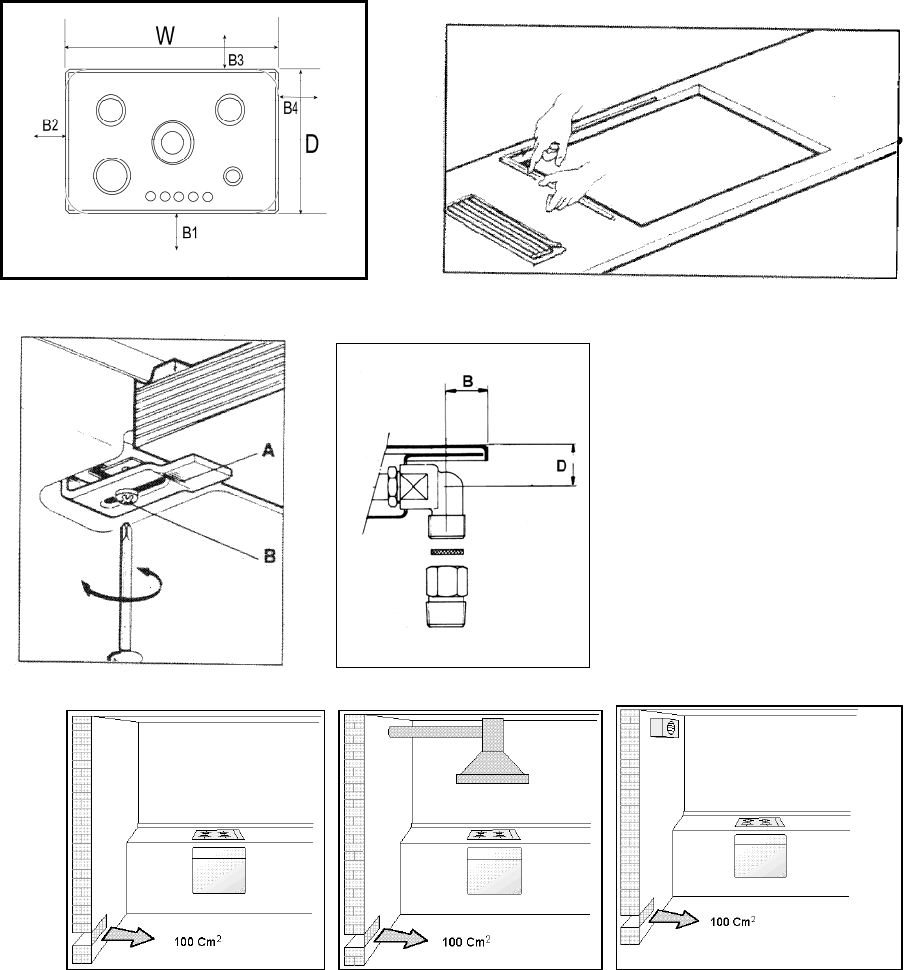
Inserting the hob ......................................................................................................................................................... pag. 2
Fixing the hob – Advice about installation ................................................................................................................... pag. 3
Ventilation and airing of the premises – Connection to the gas supply ....................................................................... pag. 3
Adaptation to different types of gas ............................................................................................................................ pag. 3
Regulation of the burners ............................................................................................................................................ pag. 4
Connection to the electricity supply ............................................................................................................................. pag. 4
MAINTENANCE OF THE APPLIANCE – Replacing parts ........................................................................................ pag. 4
USE AND MAINTENANCE MANUAL ........................................................................................................................ pag. 5
Description of types of hobs ........................................................................................................................................ pag. 5
Use of the burners ....................................................................................................................................................... pag. 5
Cleaning of the appliance ........................................................................................................................................... pag. 6
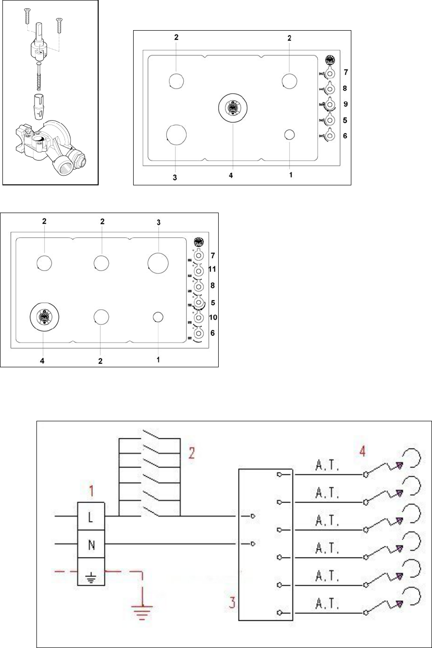
To regulate the minimum on the burners carry out the following procedure indicated below:
1) Turn on the burner and put the knob onto position MINIMUM ( small flame ).
2) Remove the knob ( Fig. 10) of the tap which is set for standard pressure. The knob is found on the bar of the tap itself.
3) Beside the tap bar on the work top, use a small screwdriver that fits the screw (gold) found on the lower part of the tap (auxiliary,
semirapid, rapid Fig. 10 (dual fig.11) and turn the fixing screw to the right or left until the flame of the burner is regulated in the most
suitable way to MINIMUM.
4) Make sure that that the flame does not go out when changing the position quickly from MAXIMUM to the MINIMUM position.
ATTENTION: The regulation described above can be carried out only with burners using natural gas, while with burners using
propane gas the screw must be fully screwed in, in a clockwise direction.
CONNECTION OF THE APPLIANCE TO THE ELECTRICITY SUPPLY:
Connection to the electricity supply must be carried out according to the norms and indications of the law in force.
Before carrying out the connection check that:
- The electric charge of the system and the sockets are suitable for the maximum power of the appliance ( see label on the lower part of
the case ).
- The socket or system is equipped with an efficient earth connection according to the norms and indications of the law currently in force.
No responsibility can be held if these indications are not respected.
When the connection to the electricity supply is made with a socket.
Fit onto the electric cable a standard plug ( if it is not provided ) which is appropriate for the charge indicated on the label. Connect up
the wires according to the diagram in Fig. 12 taking care to respect the corresponding pairs listed below:
letter L (phase) = brown coloured wire;
letter N (neutral) = blue coloured wire;
symbol”
” earth = green-yellow coloured wire;
- The electric cable must be positioned so that it cannot reach a temperature of over 75 K at any point.
- Do not use reducers, adapters or shunts for the connection as they could cause false contacts and subsequent dangerous
overheating.
When the connection is made directly with the electricity supply:
- Place a single-pole switch between the appliance and the electricity supply. The switch must be of a suitable charge for the appliance
with a minimum opening between the contacts of 3 mm.
- Remember that the earth wire must not be interrupted by the switch.
- Alternatively the electrical connection can also be protected by a differential switch of high sensitivity.
- You are strongly advised to fix the special yellow-green earth wire to an efficient earthing system
ATTENTION:
The appliance conforms to the EEC indication 90/396 regarding gas cooking appliances for domestic use.
All our appliances are designed and produced according to the European norms EN 60 335-1 and EN 60 335-2-6 and additional
relative amendments. The appliances conform with the indications of the European Low Tension Directive 73/23 and 93/68 as
well as conforming with the indications of the European directive 89/336 regarding electromagnetic compatibility.
MAINTENANCE OF THE MACHINE
CHANGING THE PARTS
Before carrying out any maintenance work, disconnect the appliance from the gas and electric supply.
To replace different components such as burners, taps and electrical parts you must take out the hob from the kitchen unit by releasing
the fixing hooks, unscrew the fixing screws of the burners on the work top, unscrew the fixing nuts of the electric plates which are visible
on the lower part of the hob and remove the worktop in order to carry out the replacement of the defective parts.
NOTE: If the taps need replacing you also need to unscrew the two fixing screws of the gas ramp at the bottom of the hob which are
found on the upper part of the latter.
For appliances equipped with automatic “ON” switches you must dismantle the “ON” switch chain before replacing the taps.
You are advised to change the seal on the tap every time you replace a tap in order to ensure a perfect hold between the body and
ramp.
WARNING: The electric cable which is provided with the appliance is connected to the appliance with a type X connection (in
accordance with the norms EN 60335-1, EN 60335-2-6 and successive variations) and thus can be replaced with the same type of cable
as that installed without using special tools.
In the event of wear or damage to the mains cable, replace it following the indications shown below.Type/ section of mains cable
H05RR-F 3x0,75 mm2
WARNING: If you replace the electric mains cable the installer must have the earth conductor about 2 cm longer than the phase
conductors and must also take heed of the warnings regarding electric connection.
Oiling the taps: (This must be carried out by qualified staff from a technical assistance centre)
If a tap becomes difficult to move you must oil the tap, without delay, following the instructions given below:
1) Dismantle the main part of the tap by unscrewing the two screws that can be found on the bar of the tap itself. (Fig. 13)
2) Take out and clean the holding cone and its setting with a cloth soaked in diluent.
3) Oil the cone lightly with the special oil.
4) Insert the cone, move it a few times, take it out again, remove the excess oil and make sure that the areas where the gas flows are
not obstructed.
5) Reassemble all the pieces in the reverse order to that followed for the dismantling and check that the tap is working properly.
USE AND MAINTENANCE MANUAL
DESCRIPTION OF HOBS
Descriptions
5
DESCRIPTIVE CAPTION FOR HOB DESCRIPTION OF HOBS
1. Small Burner Model 5 Burner Fig. 14
2. Medium burner Model 6 BurnerFig. 15
3. Rapid burner
4. Dual burner
5. Front left side burner control knob
6. Front right side burner control knob
7. Rear right side burner control knob
8. Rear left side burner control knob
9. Central burner control knob
10. Front central side burner control knob
11. Central rear side burner control knob
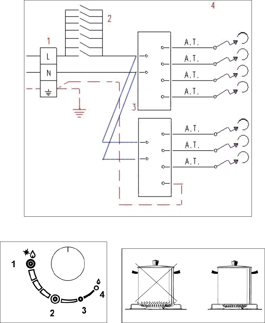
CAPTION FOR ELECTRICAL DIAGRAM
(Diagrams fig. 16 fig.17)
1 Electric panel
2 Lighter button
3 Ignition device
4 Lighting plugs
L Brown (phase)
N Blue (neutral)
’ Yellow/Green (earth)
USE OF THE BURNERS
On the control panel above every knob there is a diagram which indicates which burner the knob in question refers to. The burners can
be turned on in several ways according to the type of appliance and its individual features:
- Manual “On” switch ( this is always possible even if the electric current is cut off ): Turn the knob corresponding to the selected
burner in an anticlockwise direction so that the knob is at MAXIMUM (this corresponds to a large flame) and then put a lit match to the
burner.
- Electric “On” switch: Turn the knob corresponding to the selected burner in an anticlockwise direction so that the knob is at
MAXIMUM (this corresponds to a large flame) and then press the lighter button and let it go as soon as the burner is alight..
- Automatic Electric “On” switch: Turn the knob corresponding to the selected burner in an anticlockwise direction so that the knob is
at MAXIMUM (this corresponds to a large flame) and then press in the knob. Let it go as soon as the burner is alight.
- “On “ switch for burners with safety device ( thermocouples ): Turn the knob corresponding to the selected burner in an
anticlockwise direction so that the knob is at MAXIMUM (this corresponds to a large flame) and then use one of the lighting devices
described above. When the burner is lit keep the knob pressed in for about 10 seconds in order to allow the flame to heat up the
thermocouple. If the burner goes out when letting the knob go, repeat the operation all over again.
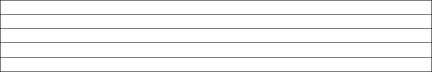
- Use of the Dual burner (Fig.18)
This model controls both the central and the external crown of the burner with just one valve.
To ignite the central crown and the external crown of the burner, press and turn the knob to the maximum delivery position 1
and hold it down until ignition; in this position both the internal and the external flame are at maximum.
Turn the knob to position 2 to have the external crown at minimum and the internal crown at maximum flame
Turn the knob to position 3 to have the internal crown at maximum and the external crown off
Turn the knob to position 4 to have the internal crown at minimum and the external crown off.
N.B.: You are advised not to try and light a burner if its flame divider is not correctly in place.
Advice for the best use of the burners:
- Use suitable pans for each burner ( see tab. n° 4 and Fig. 19).
- When boiling point is reached turn the knob on to MINIMUM.
- Always use pans with a lid.
TABLE N°4: Recommended pan diameters.
BURNER PAN DIAMETERS recommended (cm.)
Small 9 - 14
Medium 14 - 26
Large 18 - 26
Dual 22 - 26
ATTENTION: use containers with a flat bottom
ATTENTION: If there is no electric current you can light the burners with matches.
Lighting the burners with safety thermocouples can only be carried out when the knob is on MAXIMUM (large flame) .When
cooking food with oil or fat which can easily set alight, the user must not leave the appliance.
Do not use sprays near the appliance when it is in use. When using the burners make sure that the pan handles are in the
correct position. Keep children away. If the hob has a lid, before closing it, make sure that the surrounding work surface is
cleaned of any food that has been left there.
NOTE: The use of a gas cooking appliance produces heat and humidity in the place where it is installed. Therefore you need to
ensure that the place is well ventilated, keeping clear the natural ventilation openings (Fig. 6 ) and using the mechanical
ventilation device/ flue or electric fan ( Fig. 6A and 6B ). Intensive or prolonged use of the appliance may require additional
entilation such as by opening a window or an increased ventilation efficiency obtained by increasing the power of the
echanical ventilators if it is present.
CLEANING OF THE APPLIANCE
Before carrying out any cleaning operation disconnect the appliance from the electric mains and turn off the main tap which
supplies the appliance with gas.
Cleaning the worktop: Periodically the burner heads, enamelled steel grills, enamelled lids and flame dividers must be cleaned with
warm soapy water, rinsed and dried well.
Any liquid which overflows from the pan must always be removed with a cloth.
6
If opening or closing any tap is difficult do not force it but ask for an urgent check from the technical assistant.
Cleaning of the enamelled parts: To maintain the features of the enamelled parts they must be cleaned frequently with soapy water.
Never use abrasive powders. Avoid leaving acid or alkaline substances on the enamelled parts (vinegar, lemon juice, salt, tomato juice
etc.) and washing the enamelled parts when they are still warm.
Cleaning of the stainless steel parts: Clean the parts with soapy water and then dry them with a soft cloth. The shininess is
maintained by periodically cleaning with the special products normally available on the market. Never use abrasive powders.
Cleaning of the burner flame dividers: as they are not fixed, the flame dividers can be cleaned by simply removing them and cleaning
with soapy water. After drying them well and checking that the holes are not blocked, put them back into their correct position.
(FR) (BE) LISEZ ATTENTIVEMENT CETTE NOTICE AVANT D'INSTALLER ET D'UTILISER L'APPAREIL.
Les instructions contenues dans cette notice ne sont valables que pour les pays dont le sigle d'identification est reporté sur la
couverture de la notice et sur la plaquette de l'appareil.
7
Le fabricant décline toute responsabilité en cas de dégâts à des personnes ou à des biens provoqués par une mauvaise
installation ou une utilisation impropre de l'appareil.
Le fabricant n'est pas responsable des inexactitudes éventuelles présentes dans cette notice, dues à des erreurs d'impression ou de
transcription Les dessins et les illustrations aussi ne sont donnés qu'à titre indicatif.
Le fabricant se réserve le droit d'effectuer toutes les modifications qu'il jugera nécessaire et utile, sans toucher néanmoins aux
principales caractéristiques de sécurité et de fonctionnement.
TABLE DES MATIERES :
NOTICE TECHNIQUE POUR L'INSTALLATEUR...................................................................................................... page 7
Encastrement de la table de cuisson......................................................................................................................... page 7
Fixation de la table de cuisson - Conseils sur l'installation......................................................................................... page 8
Ventilation et aération de la pièce - Raccordement au réseau du gaz........................................................................ page 8
Adaptation aux différents types de gaz...................................................................................................................... page 8
Réglage des brûleurs................................................................................................................................................. page 9
ENTRETIEN DE LA TABLE - Changement des composants .................................................................................. page 9
NOTICE DE MODE D'EMPLOI ET D'ENTRETIEN................................................................................................... page 10
Descriptions des modèles de tables de Cuisson....................................................................................................... page 10
Utilisation des brûleurs.............................................................................................................................................. page 10
Nettoyage de la table................................................................................................................................................. page 11
Libble takes abuse of its services very seriously. We're committed to dealing with such abuse according to the laws in your country of residence. When you submit a report, we'll investigate it and take the appropriate action. We'll get back to you only if we require additional details or have more information to share.
Product:
Forumrules
To achieve meaningful questions, we apply the following rules:
First, read the manual;
Check if your question has been asked previously;
Try to ask your question as clearly as possible;
Did you already try to solve the problem? Please mention this;
Is your problem solved by a visitor then let him/her know in this forum;
To give a response to a question or answer, do not use this form but click on the button 'reply to this question';
Your question will be posted here and emailed to our subscribers. Therefore, avoid filling in personal details.
Register
Register getting emails for Bertazzoni QB36600X at:
new questions and answers
new manuals
You will receive an email to register for one or both of the options.
Get your user manual by e-mail
Enter your email address to receive the manual of Bertazzoni QB36600X in the language / languages: English, French as an attachment in your email.
The manual is 0,51 mb in size.
You will receive the manual in your email within minutes. If you have not received an email, then probably have entered the wrong email address or your mailbox is too full. In addition, it may be that your ISP may have a maximum size for emails to receive.
The manual is sent by email. Check your email
If you have not received an email with the manual within fifteen minutes, it may be that you have a entered a wrong email address or that your ISP has set a maximum size to receive email that is smaller than the size of the manual.
The email address you have provided is not correct.
Please check the email address and correct it.
Your question is posted on this page
Would you like to receive an email when new answers and questions are posted? Please enter your email address.