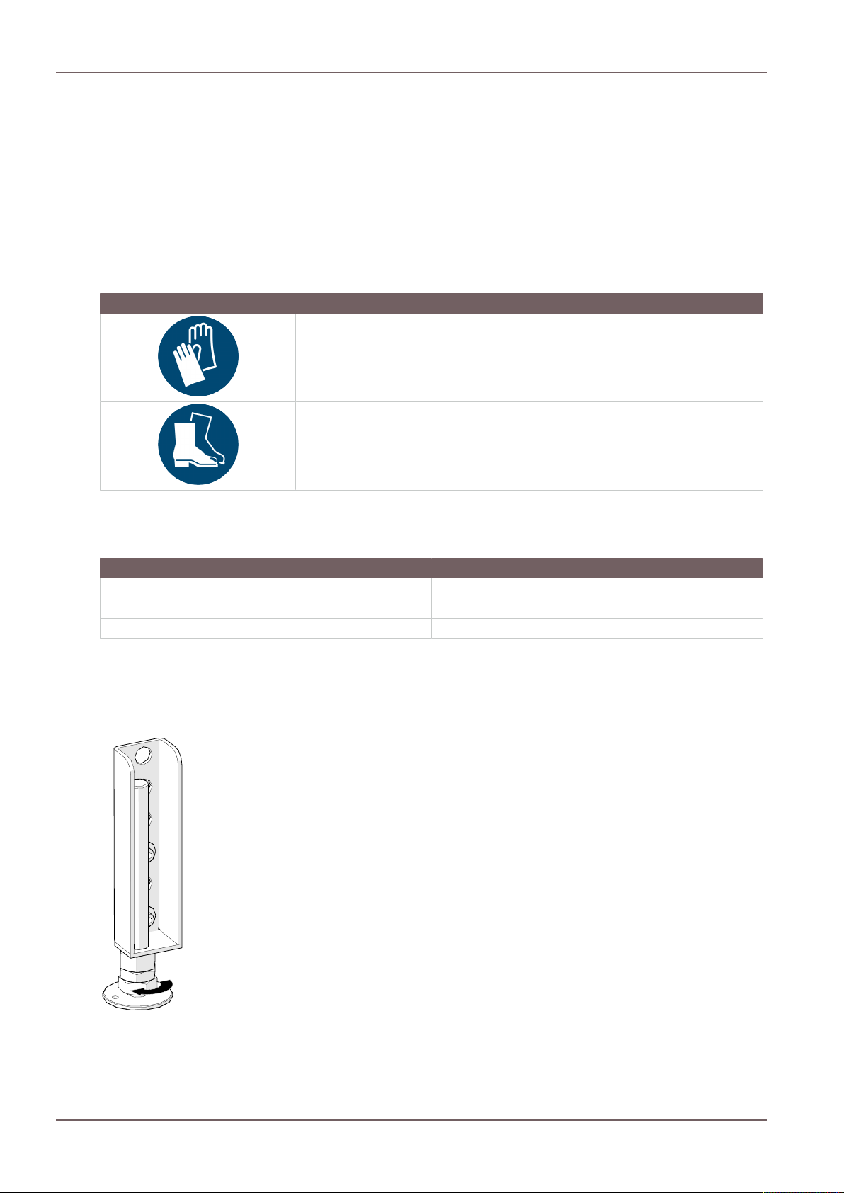
4.2Identifying the tools.............................................................................................................................12
5.3Data for the chimney/flue dimensioning..........................................................................................50
6Transport and storage.........................................................................................................................................51
10Connection to ceramic flues..............................................................................................................................67
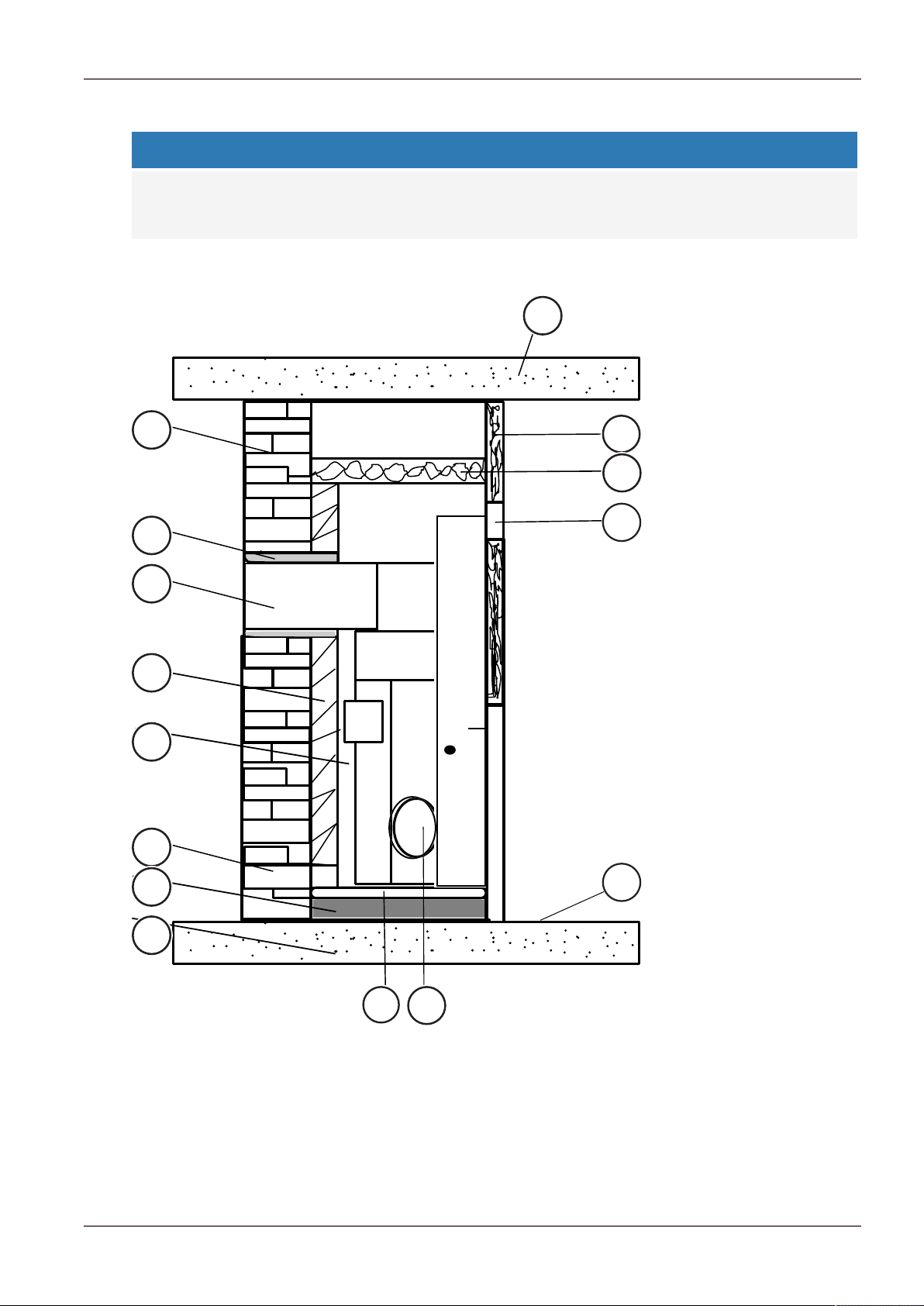
10.1Stove with ceramic flue.......................................................................................................................68
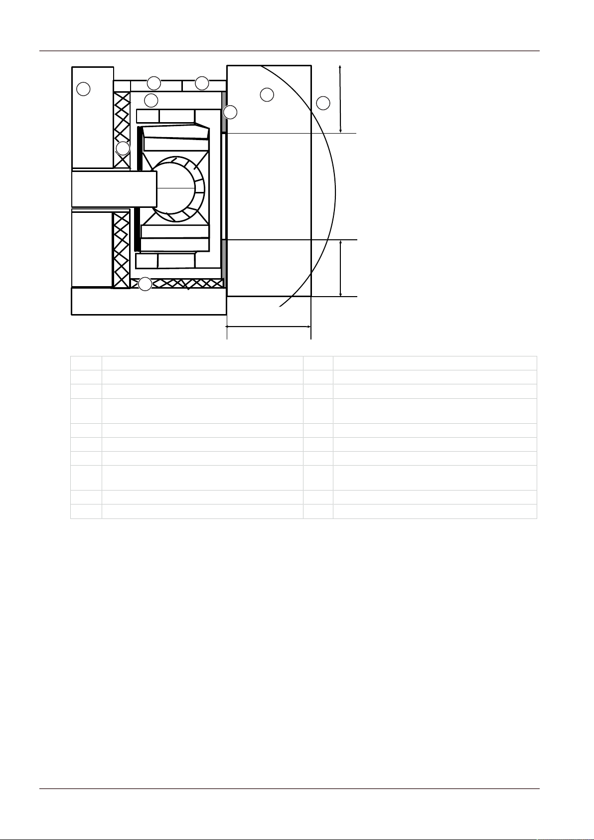
10.2Connection to heat recovery surfaces..............................................................................................69
11.1Risks and dangers................................................................................................................................70
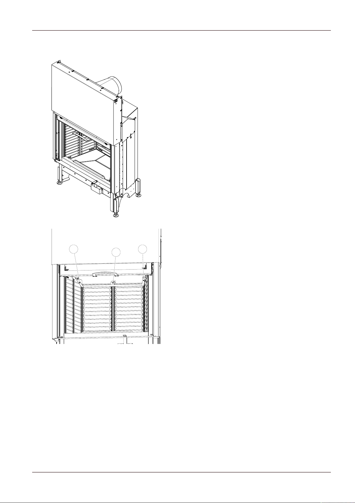
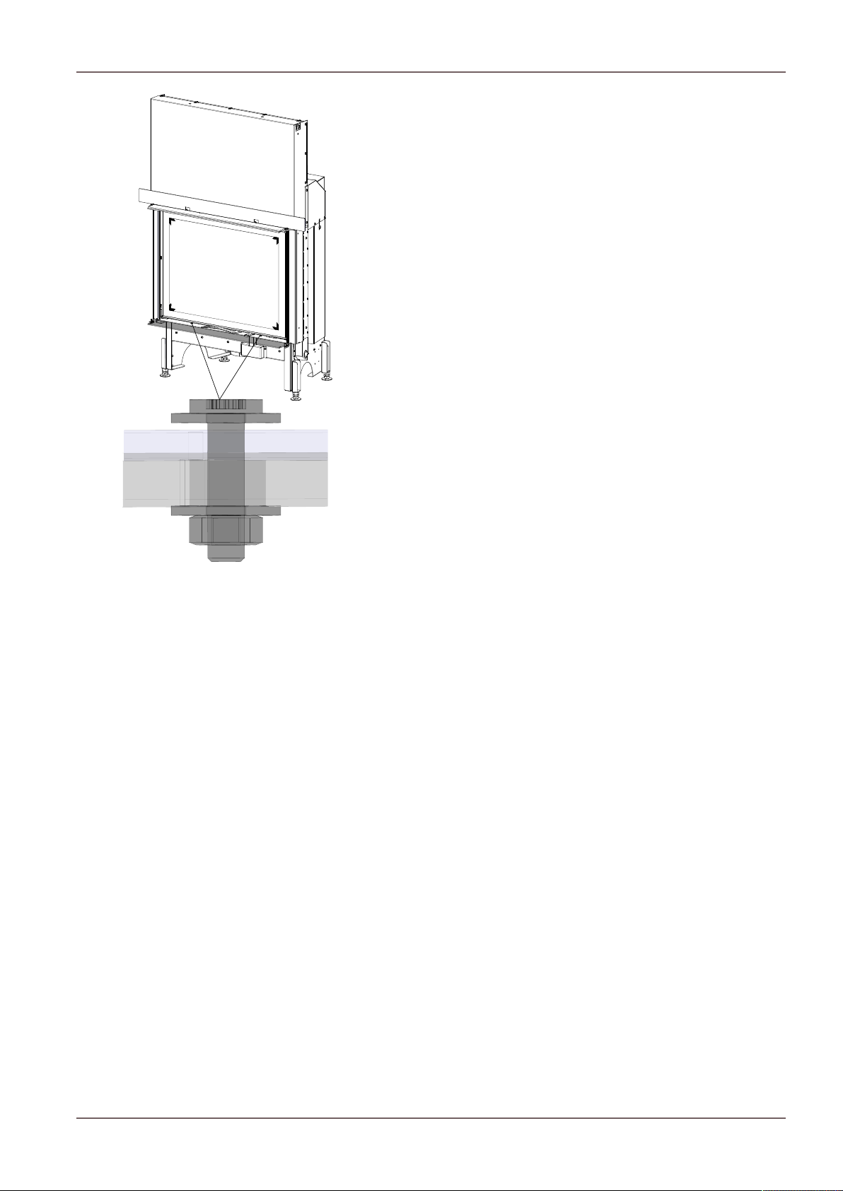
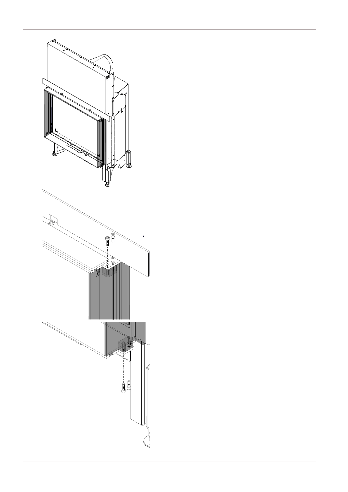
11.2.1Placing the fireplace insert.................................................................................................................70
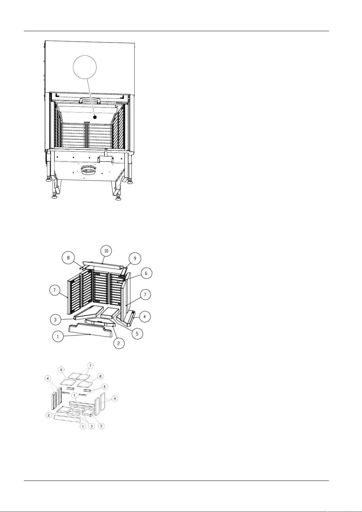
11.2.2Dismantling the Keramott...................................................................................................................71
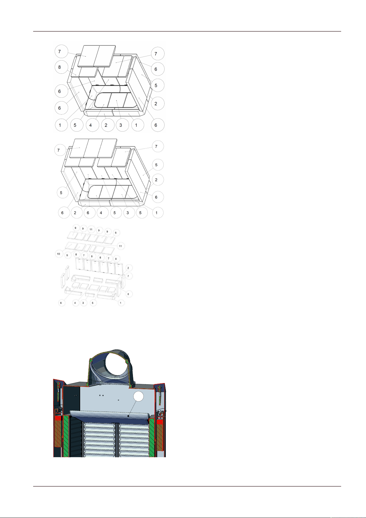
11.2.3Installing the firebox lining (Keramott)..............................................................................................72
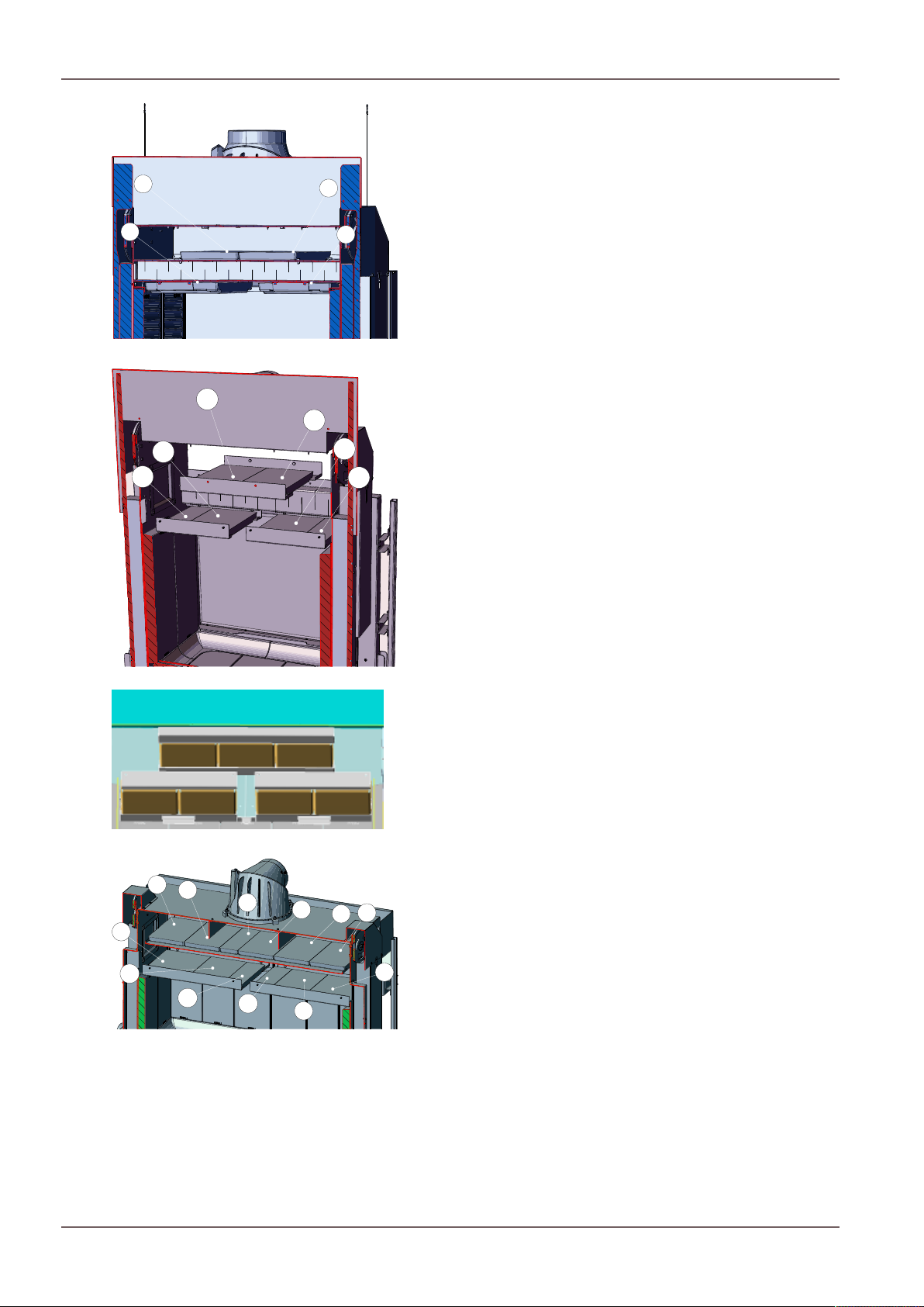
11.2.4Install the deflector plates..................................................................................................................73
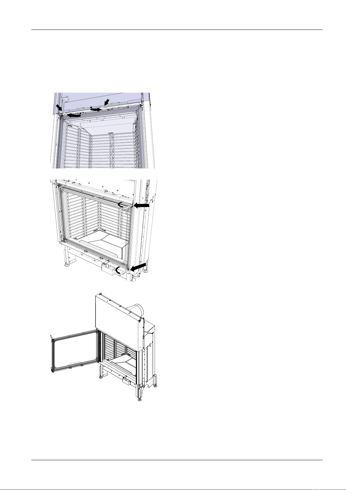
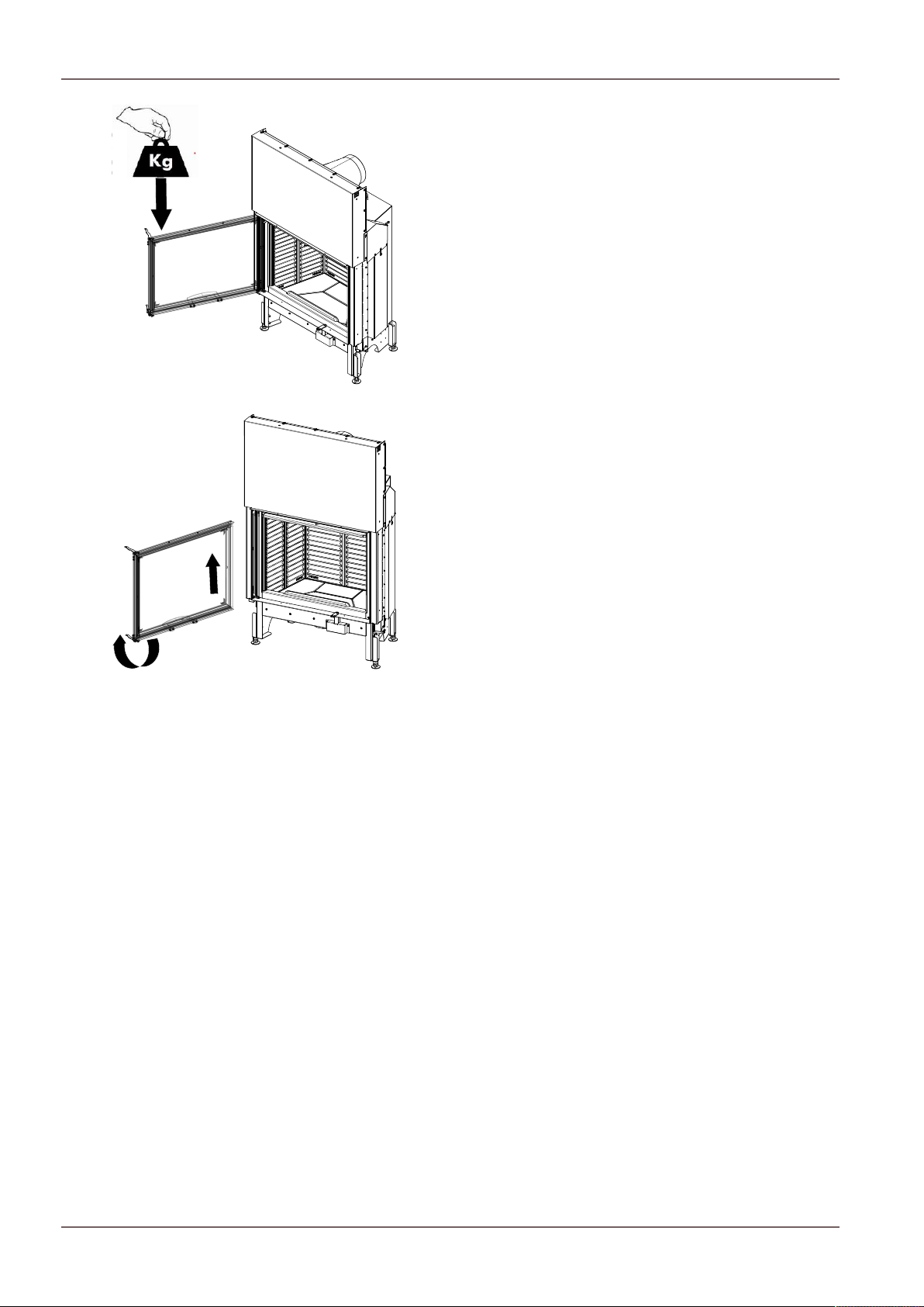
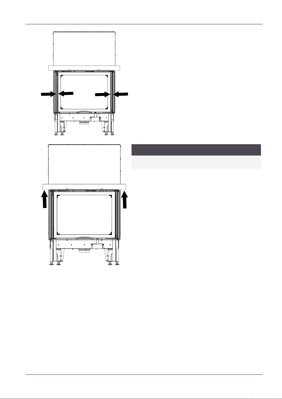
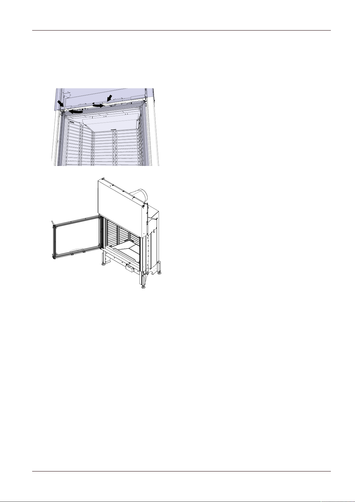
11.2.5Removing the door..............................................................................................................................75
11.2.6Converting door to construction type BA2......................................................................................76
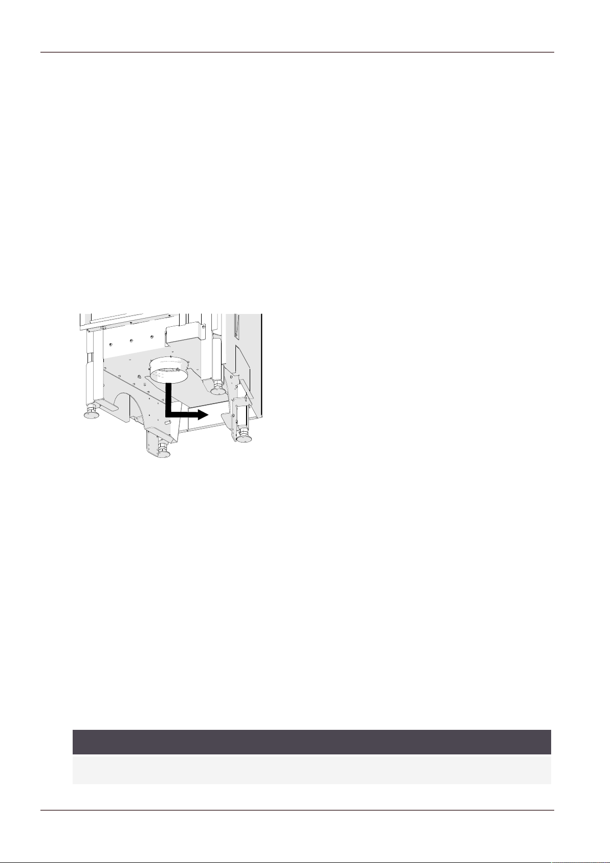
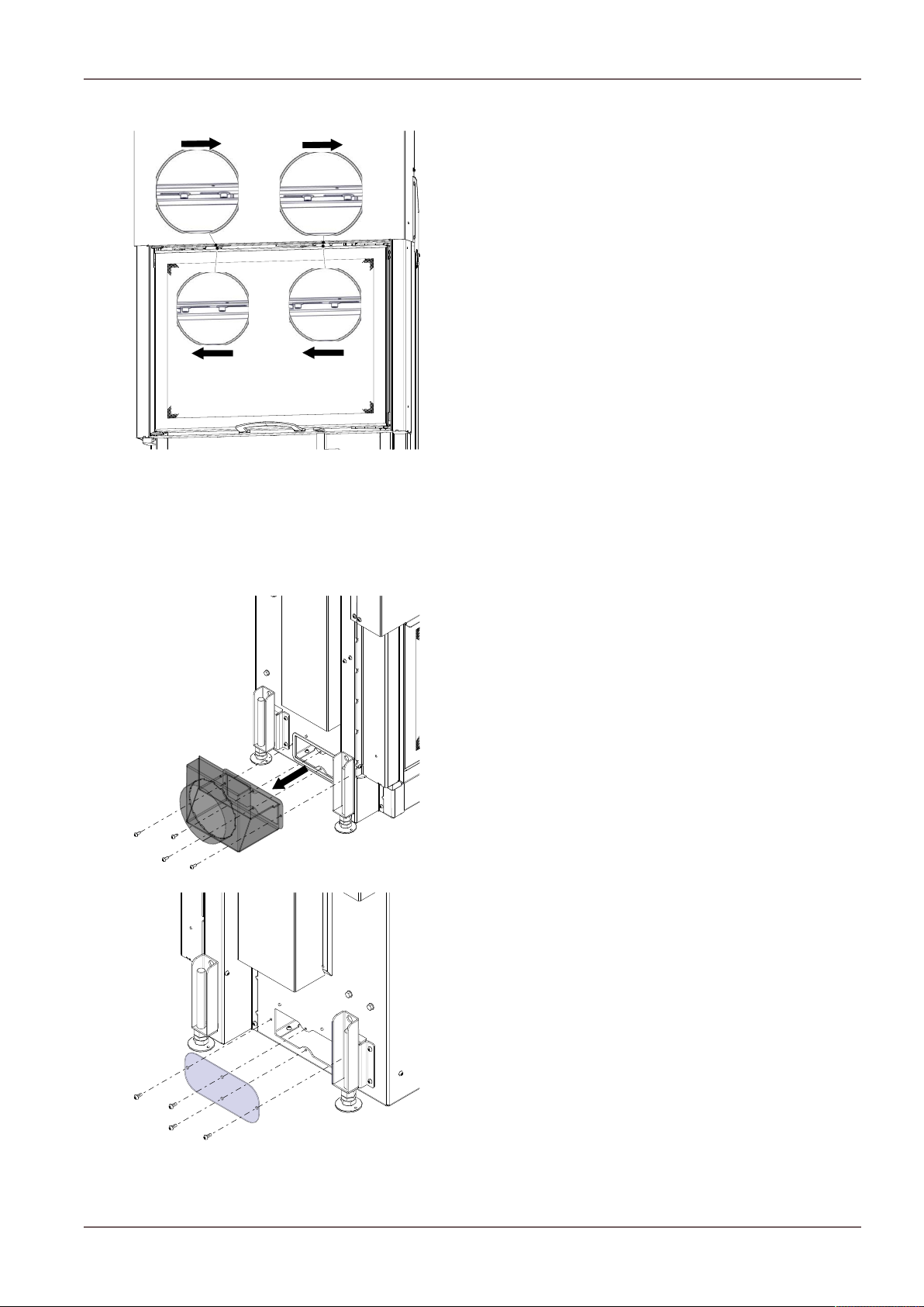
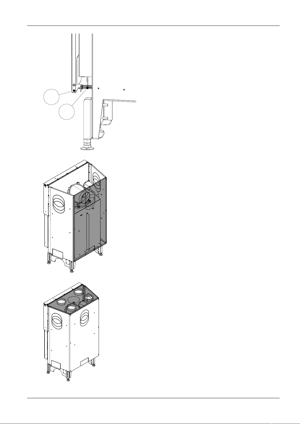
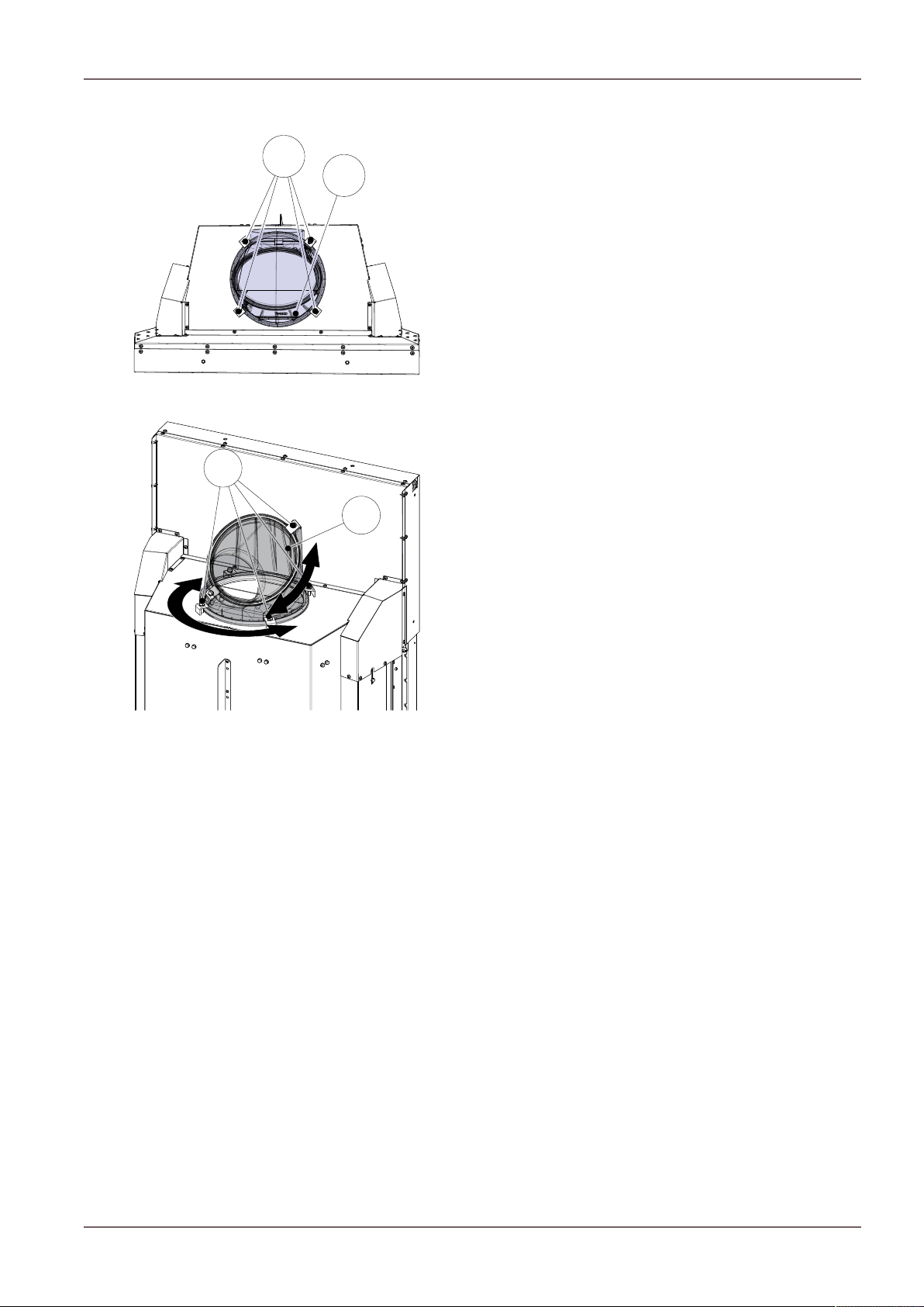
11.2.7Converting the combustion air collar...............................................................................................77
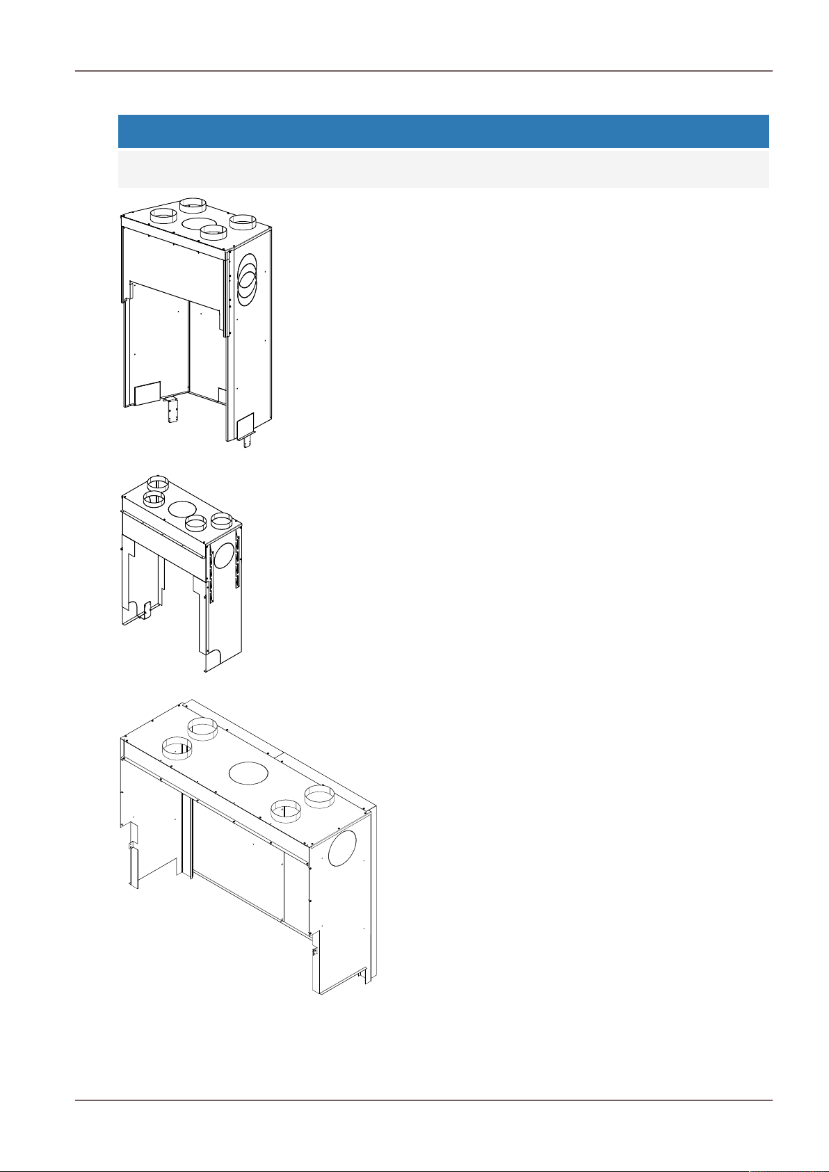
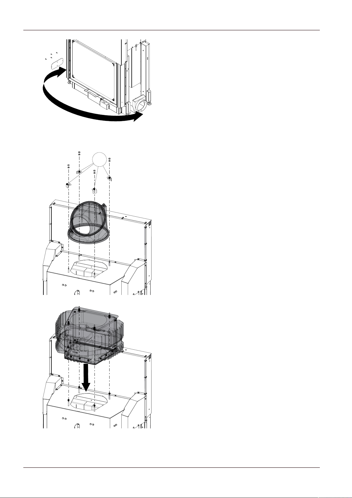
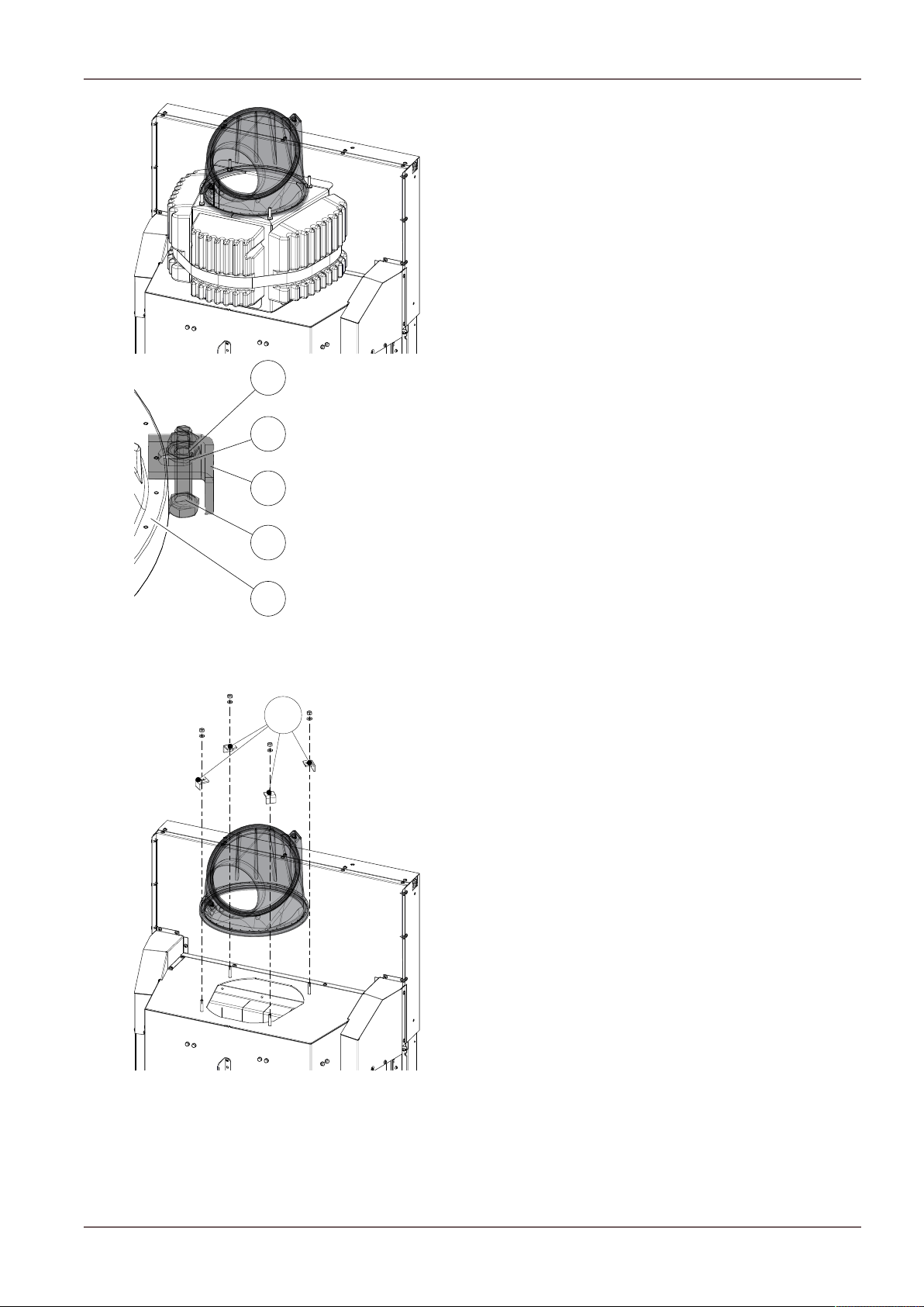
11.2.8Mounting large top storage box........................................................................................................78
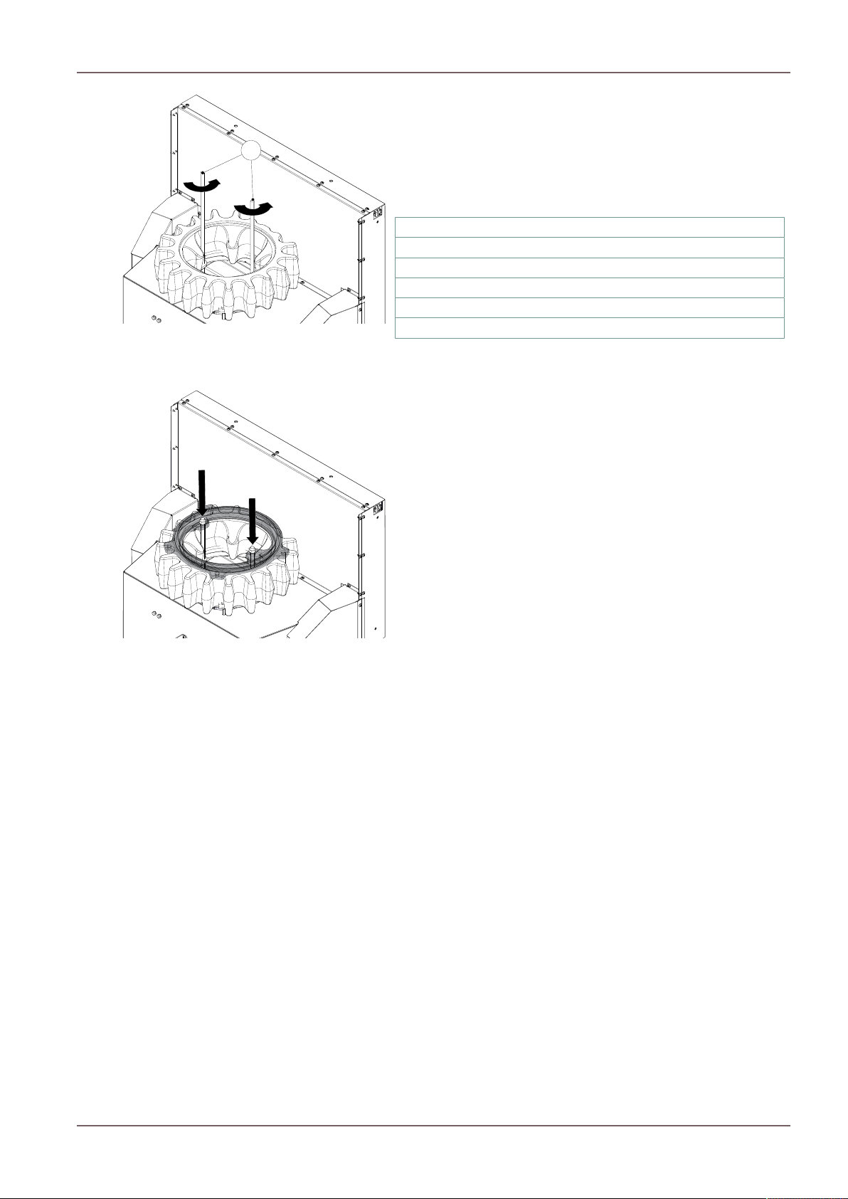
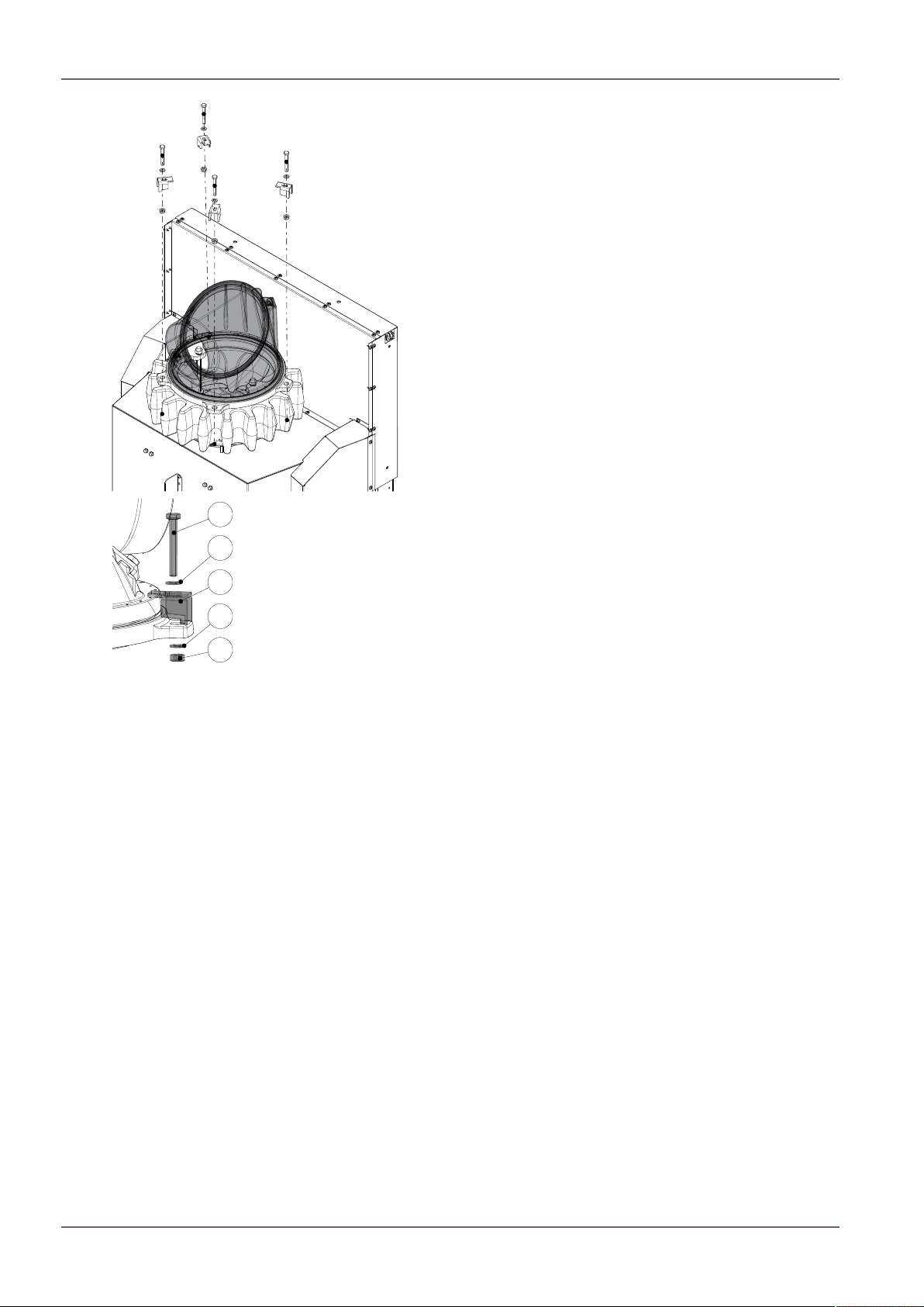
11.2.9Mounting top storage bricks..............................................................................................................79
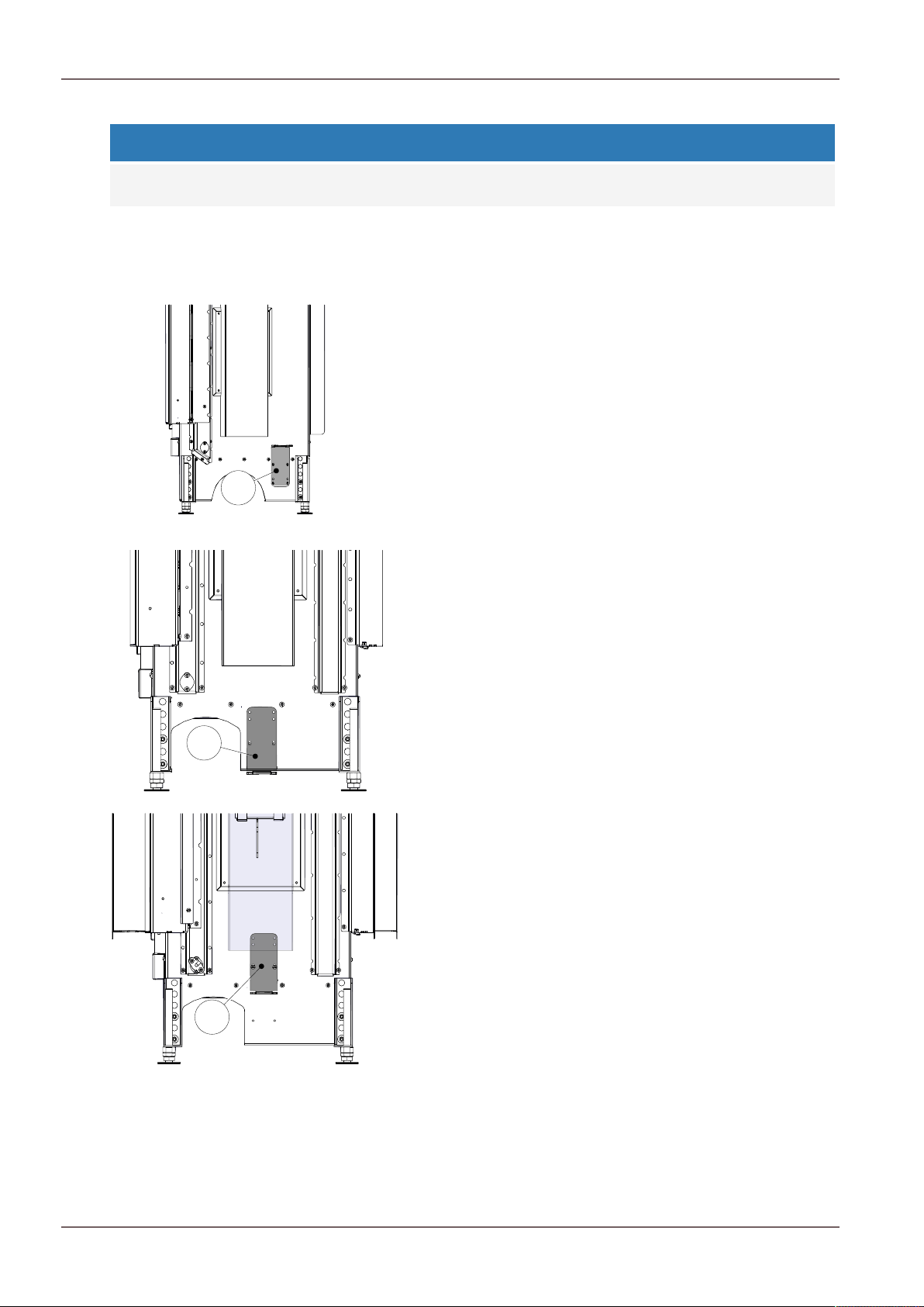
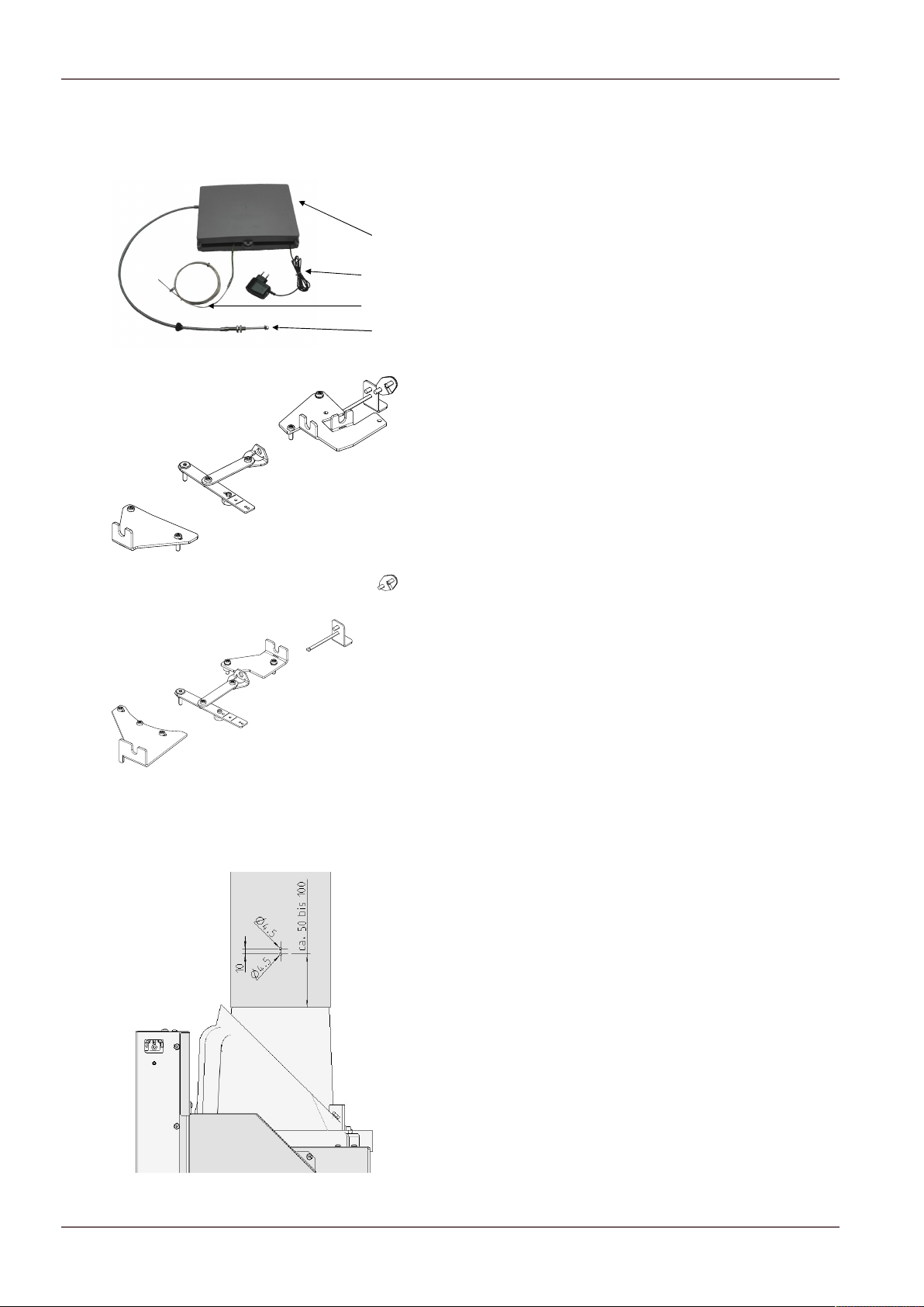
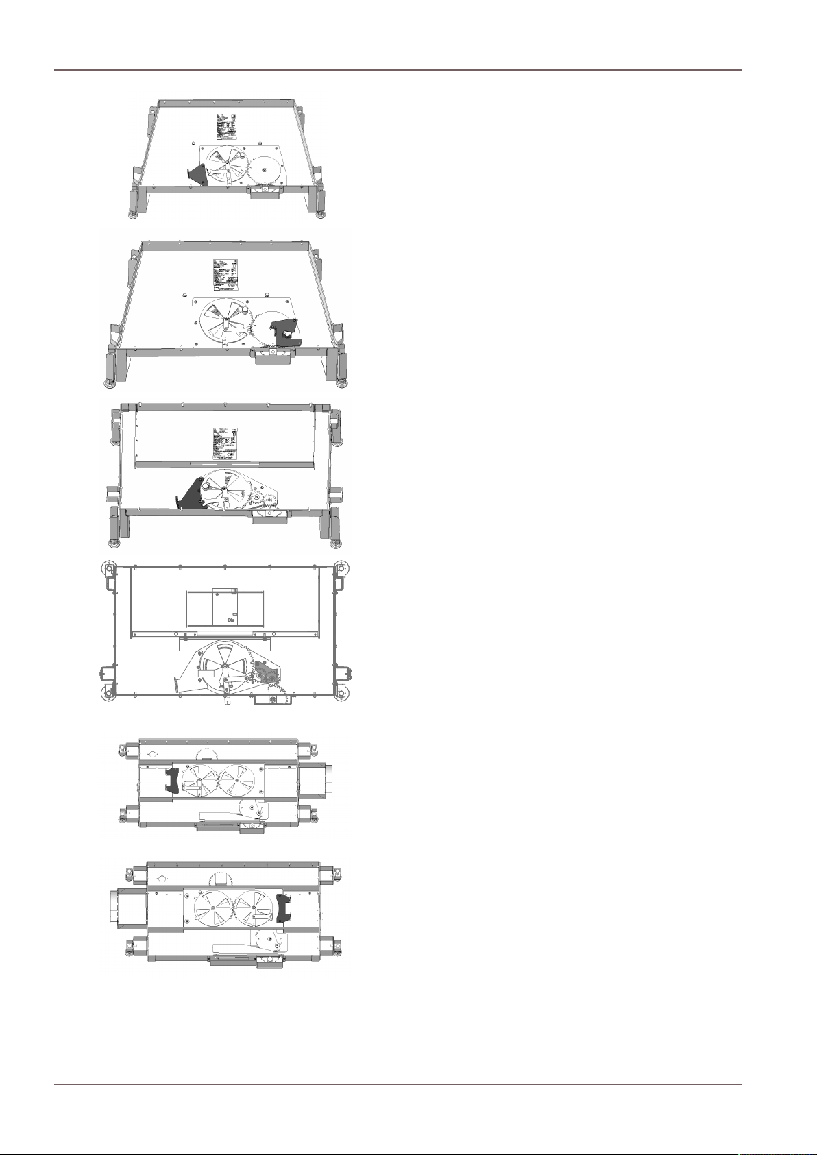
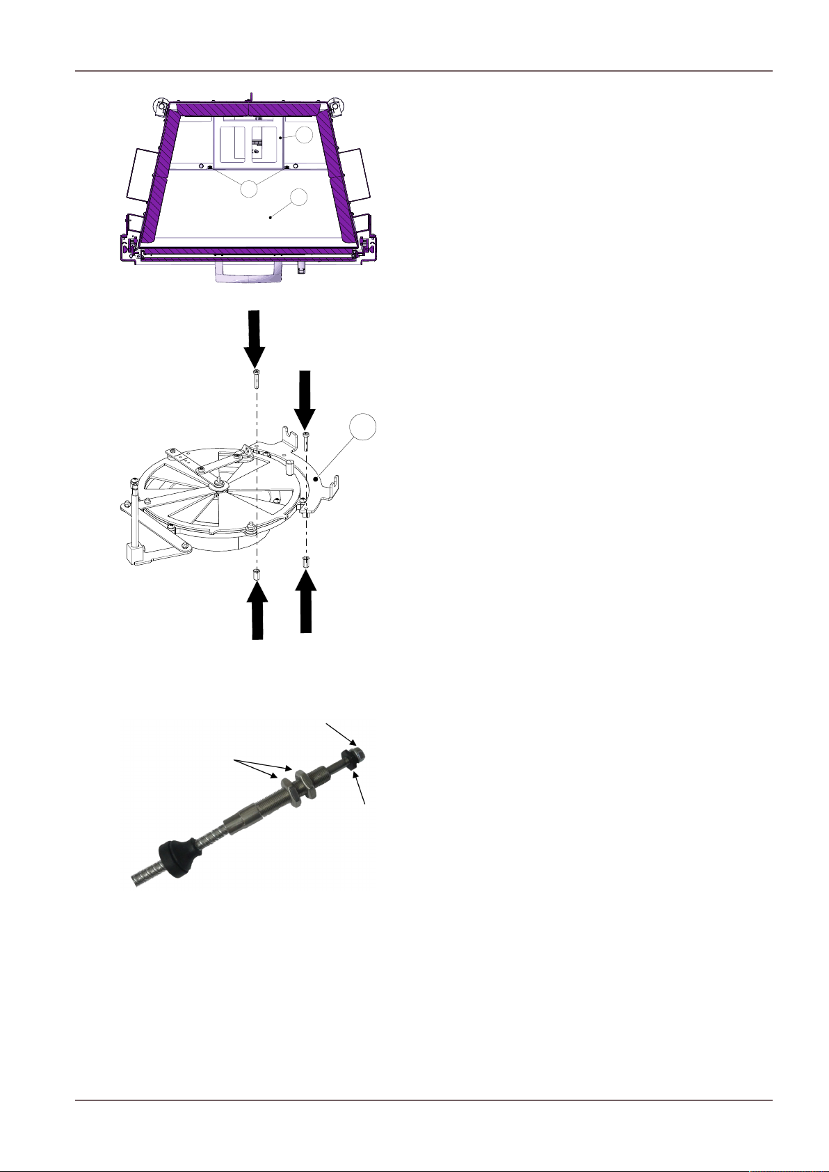
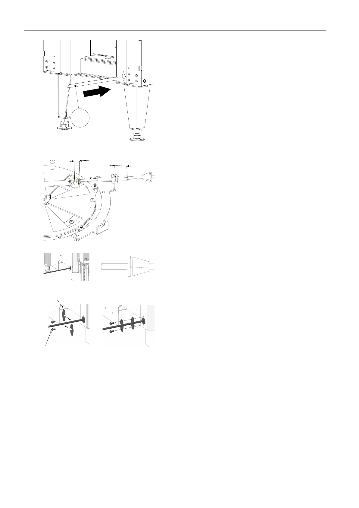
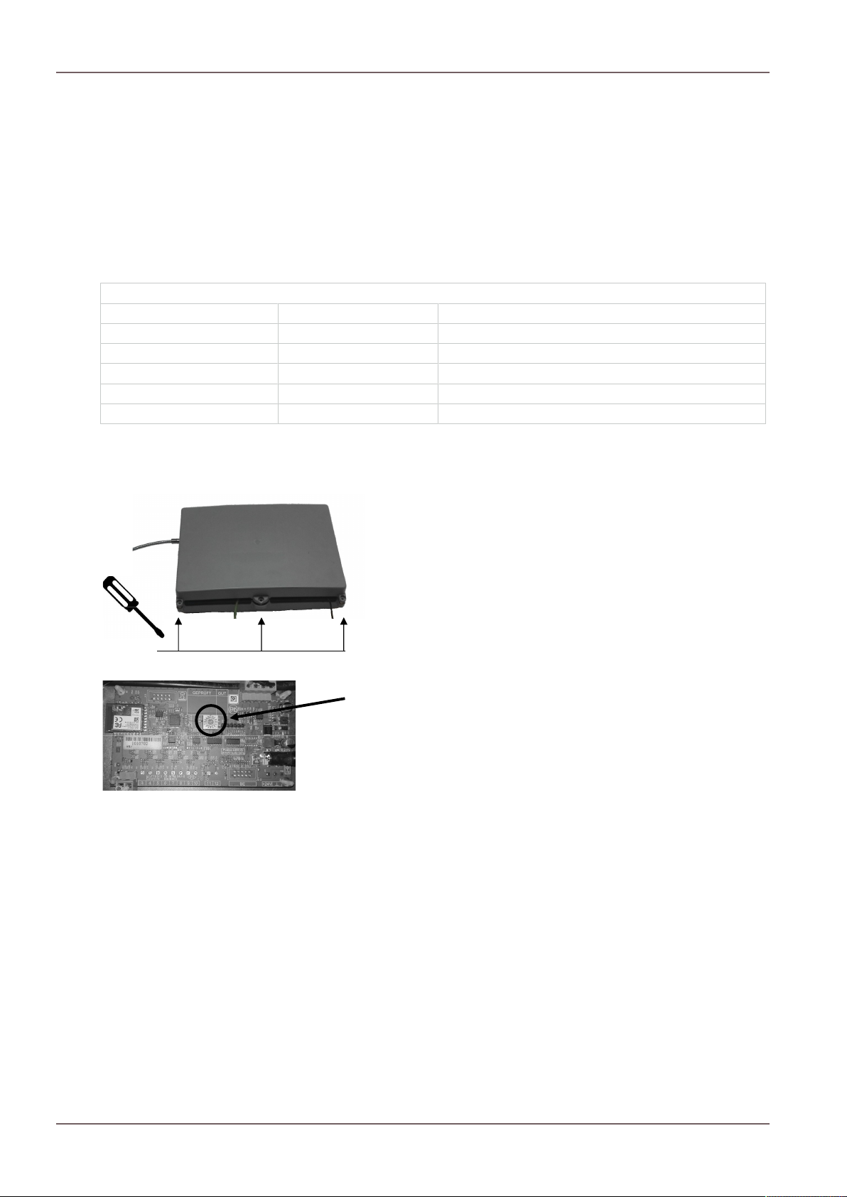
11.2.10Installing the HMS ...............................................................................................................................83
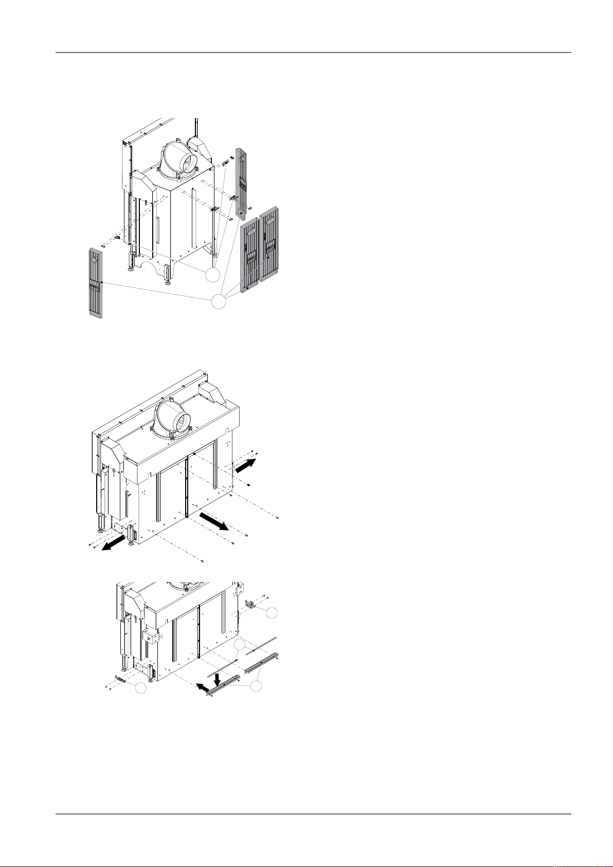
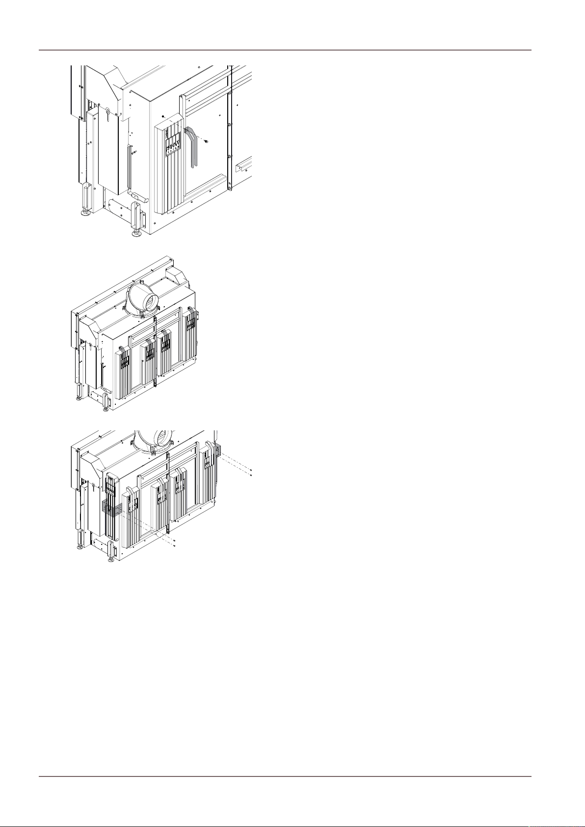
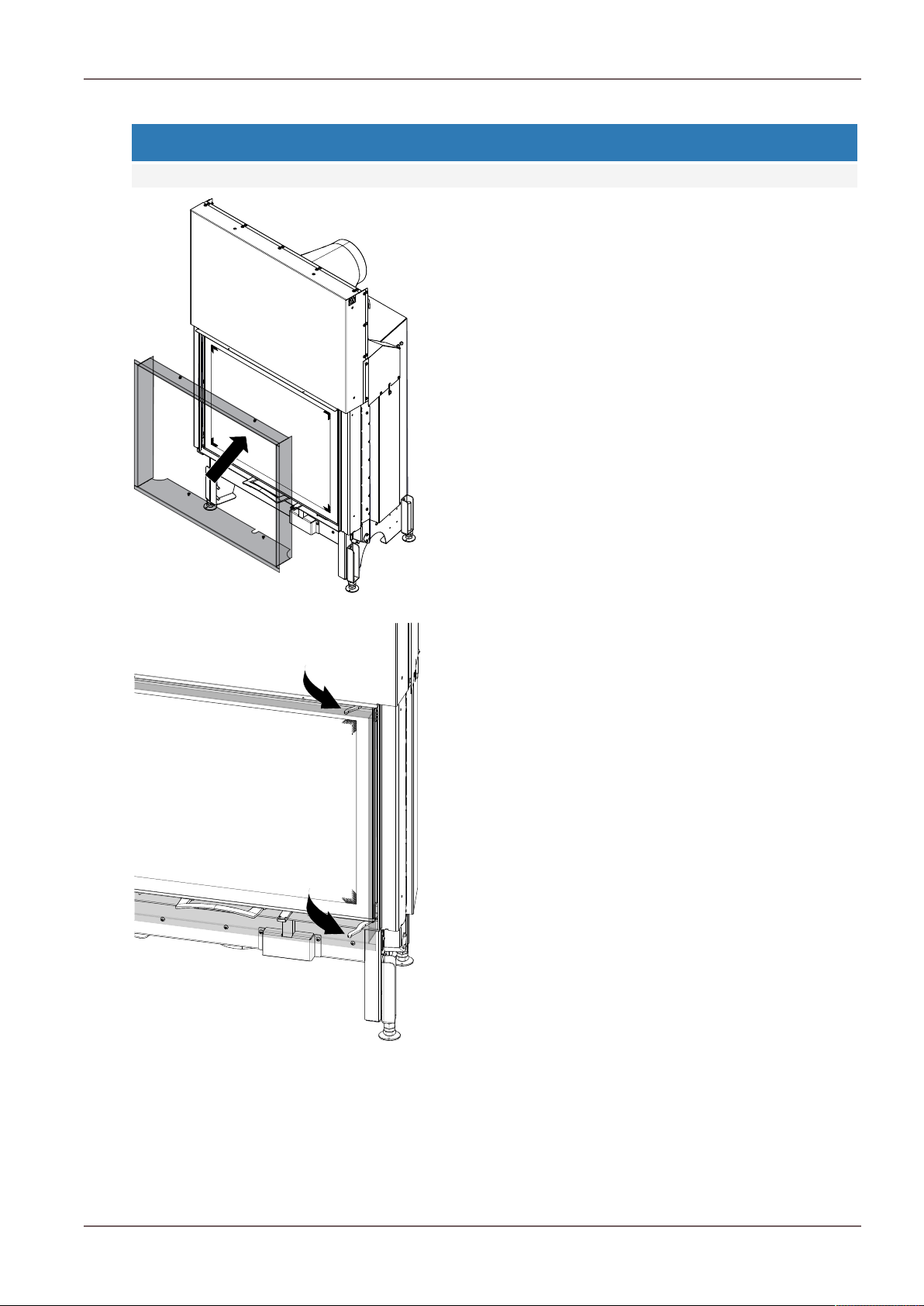
11.2.11Mounting the designer frame............................................................................................................85
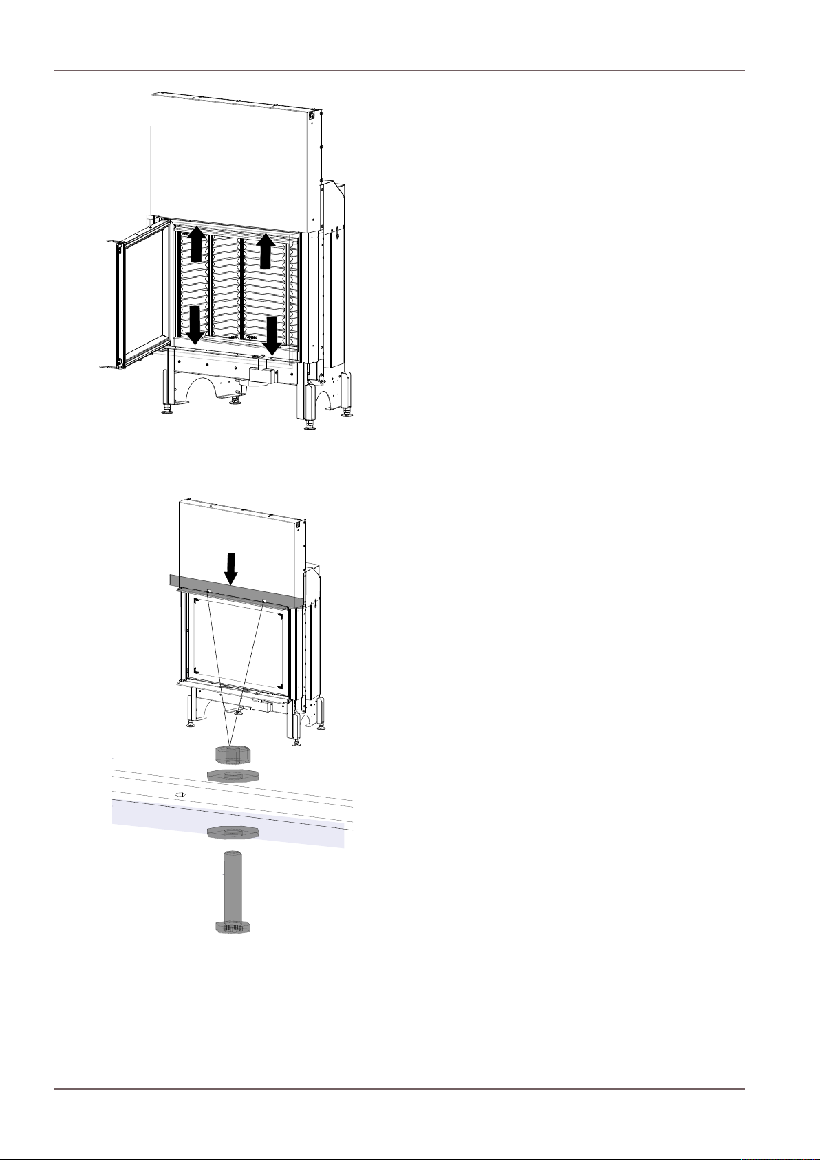
11.2.12Mounting the convection cladding...................................................................................................90
14.6Putting on wood..................................................................................................................................105
14.7Heating in the transition period.........................................................................................................106
14.8Heating with the ceramic flue (heat recovery surface)....................................................................106
20Guarantee and warranty ....................................................................................................................................116
21Start up log...........................................................................................................................................................117
Libble takes abuse of its services very seriously. We're committed to dealing with such abuse according to the laws in your country of residence. When you submit a report, we'll investigate it and take the appropriate action. We'll get back to you only if we require additional details or have more information to share.
Product:
Forumrules
To achieve meaningful questions, we apply the following rules:
First, read the manual;
Check if your question has been asked previously;
Try to ask your question as clearly as possible;
Did you already try to solve the problem? Please mention this;
Is your problem solved by a visitor then let him/her know in this forum;
To give a response to a question or answer, do not use this form but click on the button 'reply to this question';
Your question will be posted here and emailed to our subscribers. Therefore, avoid filling in personal details.
Register
Register getting emails for Austroflamm Fireplace inserts slied flat II - Kamineinsatz Schieb flach II at:
new questions and answers
new manuals
You will receive an email to register for one or both of the options.
Get your user manual by e-mail
Enter your email address to receive the manual of Austroflamm Fireplace inserts slied flat II - Kamineinsatz Schieb flach II in the language / languages: English as an attachment in your email.
The manual is 14.06 mb in size.
You will receive the manual in your email within minutes. If you have not received an email, then probably have entered the wrong email address or your mailbox is too full. In addition, it may be that your ISP may have a maximum size for emails to receive.
Others manual(s) of Austroflamm Fireplace inserts slied flat II - Kamineinsatz Schieb flach II
If you have not received an email with the manual within fifteen minutes, it may be that you have a entered a wrong email address or that your ISP has set a maximum size to receive email that is smaller than the size of the manual.
The email address you have provided is not correct.
Please check the email address and correct it.
Your question is posted on this page
Would you like to receive an email when new answers and questions are posted? Please enter your email address.